Embed Size (px)
Citation preview
PRODUCTION SECTION
LOAD-CARRYING CAPACITY OF POLYMER TAPE ROLLS
UNDER IMPACT LOADS
6. S. Umanskii, N. S. Shidlovskii, V. V. Kryuchkov, S. V. Grishko, and L. L. Stezhko
UDC 539.3:678
The appratus, method, and result of experimental investigation of load-carrying capacity of rolled magnetic tapes subjected to impact and thermal effects are described. Analysis of the basic regularities of loss of load-carrying capa- city of the rolls (lamination of turns) has facilitated determination of the safe level of impact accelerations and thermal effects which do not cause damage of rolls under multiple impacts (104...105 cycles). It is established that breakdown in compactness of rolled magnetic tapes under multiple impacts occurs due to reduction in interturn pressures (up to 30...50% of the original level). It is noted that, with increase in environmental temperature, there is sharp reduction in load-carrying capacity of rolls under the action of im- pact loads.
The steady extension of the fields of application of magnetic recorders (MR) in industry, aviation, and space technology has raised the requirements for strength and load-carrying capacity of recorders and of the rolls of polymer-base magnetic tapes (MTR) used as informa- tion carriers. During operation, the MR and MTR can be subjected to multiple or one-time loads of differing amplitudes and periods [1-3]. In a series of cases, this causes mutual displacement of the turns, irreversible deformations of tapes, or total falling apart of the roll. Variation in environmental temperature, additional thermal stresses occurring in the roll due to this, and activation of rheological effects in the polymer base of the tape lead to considerable reduction in interturn pressures and to general loss of impact strength of the roll.
It is of practical interest in the above context to investigate the load-carrying capa- city of MTR used in contemporary MR in the working range of temperatures and loads as well as to establish the basic regularities of loss of load-carrying capacity under the effect of multiple impacts with different characteristics (amplitude of acceleration, time of action, number of impact cycles, a.o.).
A lot of experience has hitherto been gained in investigating impact strength of mater- ials, various structural elements, and equipment. At the same time, there is evidetnly no information available on load-carrying capacity of MTR under impact loading.
This article is in continuation of the comprehensive studies of the stress-strain state and load-carrying capacity of polymer-base MTR under the effect of operating factors [4-8].
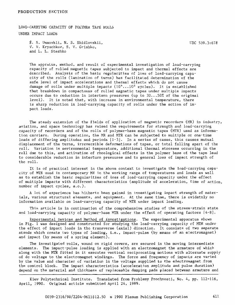
Experimental Devices and Method of Investigations. The experimental apparatus shown in Fig. 1 was designed and constructed for studying the load-carrying capacity of MTR under the effect of impact loads in the transverse (axial) direction. It consists of two separate stands which create two types of loading, i.e., impact-pulse (by means of an electromagnet) and impact (by means of a spring element).
The investigated rolls, wound on rigid covers, are secured in the moving intermediate elements. The impact-pulse loading is applied with an electromagnet the armature of which along with the MTR fitted in it executes vertical reciprocating motions with alternate supply of dc voltage to the electromagnet windings. The force and frequency of impacts are varied by the value and character of variation in the voltage supplied to the electromagnet from the control block. The impact characteristics (acceleration amplitude and pulse duration) depend on the material and thickness of replaceable damping pads placed between armature and
Kiev Polytechnical Institute. Translated from Problemy Prochnosti, No. 4, pp. 112-116, April, 1990. Original article submitted April 24, 1989.
0039-2316/90/2204-0611512.50 �9 1990 Plenum Publishing Corporation 611
/////////////////
Fig. I. Functional diagram of the stand for impact loading of MTR: I) magnetic tape rolls; 2) core; 3) electromagnet ~M-12; ~) control block; 5) fuse; 6) steel beam; 7) spring element; 8) face cam; 9) reduction gear motor; i0) striker; ii) pad; 12) solid base; 13) piezoceramic transducers; 14) oscillograph $8-II; 15) oscillograph SI-48B; 16) contact group; 17) thermal chamber; 18) heater; 19) contact thermometer; 20) fan; 21) thermoregu- lator TRKo
base of the electromagnet, The electromagnet counter BIS-62 mounted in the control block records the number of impacts~
The length of thin copper wire (0.06 mm) inserted between the turns of tape when the roll was wound serves as a device to protect the roll from further loosening after the start of lamination. The copper wire ruptures in case the turns are displaced and the control block stops voltage supply to the electromagnet.
A rigid steel beam fastened to a spring element is used for creating high impact ac- celerations.
The impact is effected as described below.
The profile element (face cam) is secured to the reduction gear motor shaft. The spring element is deformed with rotation of the cam, as a result of which, a gap is formed between the beam and pad secured to the solid base. After maximum displacement of the left end of the beam, there is a sudden separation and the beam along with the roll secured to it returns to the initial position thus producing the impact. The force and duration of impact are regulated by selection of the cam profile and pad and spring element material.
Characteristics of impact loads (acceleration, duration, et. al) were measured with the help of piezoceramic transducers (type D14-3409) secured in the cores. The signal from the transducers reaches the storage oscillograph $8-I and oscillograph SI-48B. The investi- gated signal was synchronized by using the contact group connected with the impact element.
The rolls was placed in the thermal chamber fabricated out of heat-insulating material. A heater, contact thermometer, and fan for agitating the air are located in the chamber in addition to the roll. The chamber temperature was automatically maintained with •176 accu- racy by a type TRK thermoregulator.
Technical characteristics of the experimental apparatus are as follows: up to 2600 m/sec 2 acceleration with impact-pulse loading; up to 2 impacts per second frequency of impact-pulse loading; 3~oI0 msec duration of impact-pulse loading; up to 104 m/sec 2 acceleration with impact loading; 12 impacts per minute frequency of impact loading.
The experimental set-up described caller in [6] was used for roll winding and determin- ing residual radial compressive stresses (interturn pressures)~ The tape was wound at the maximum possible speed at which it can move in the MRtrack (0.76 m/sec). In this, by cutting down the time spent on roll winding, it was possible to reduce the relaxation of residual stresses~ This has a significant effect on results of the experiment.
612
a[ m/sec 2
800 ~ .
400
200i
l I i l I
IO iO ~ iO 3 ~O ~ ~I, cycle
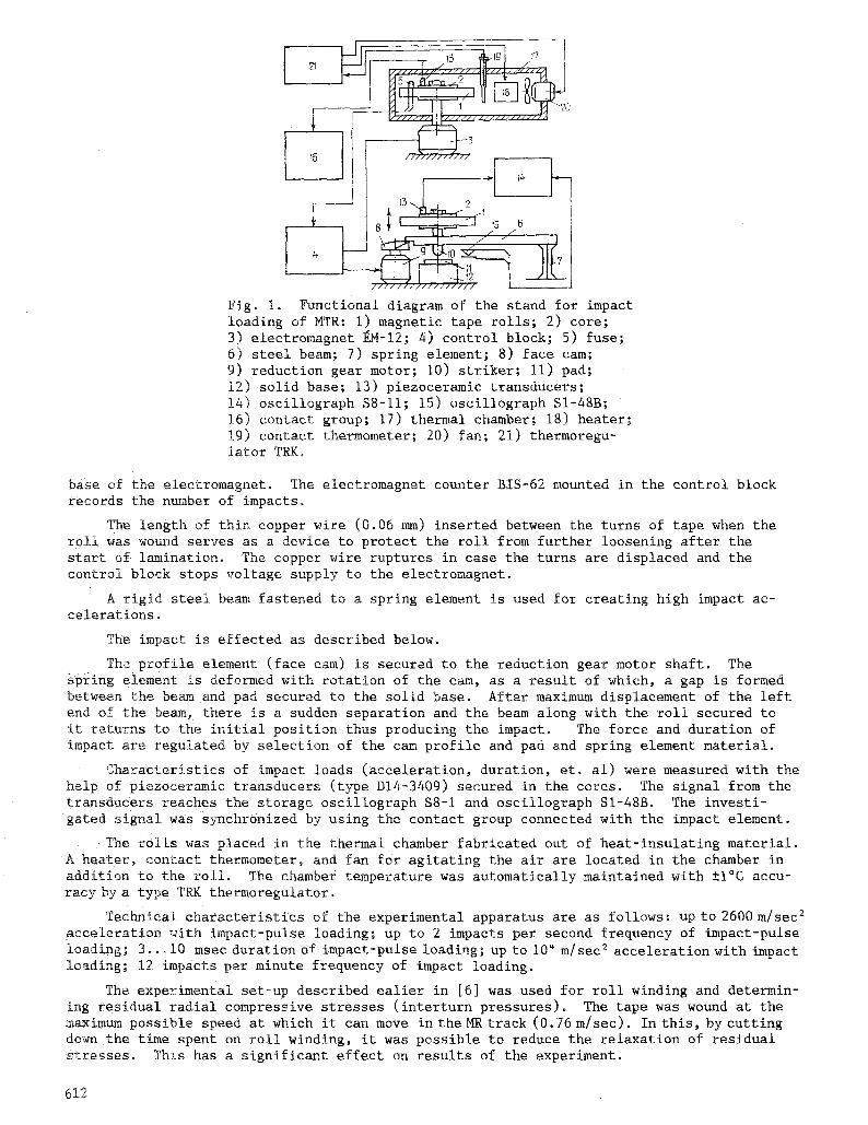
Fig. 2. Dependences of the number of impacts be- fore failure of the roll on amplitude of acceler- ation with impact of 6.~ (a) and 4...5 ms (b) durations: !) H = 0.8 N; 2) H = 1.0 N; 3) H = 1.25 N. (Dots - experimental results; solid lines - linear approximation by the method of least squares).
The formed rolls were subjected to multiple impact action. Oscillograph traces of the impact process were taken simultaneously. The acceleration amplitude and duration of ef- fect of the impact load were determined from the oscillograms. The number of impact load cycles and radius of the winding at which the displacement of turns occurred were fixed after failure of the roll (lamination).
The experiments were carried our for fixed values of amplitude with acceleration of 130...2300 m/sec 2. The pulse duration was varied over a range of 4...8 msec.
Investigated Materials. Rolls formed by winding magnetic tape on polyethylene tere- phthalate (Dacron) base were used for the investigations. One of the most widely used magnetic tapes in the country, 1-4406-6 (6.25 mm tape width, 0.036 mm overall thickness, and 0.027 mm thickness), was used.
The tape was wound into rolls using constant tensioning force for the entire radius of the winding with three fixed values of force, i.e., 0.8, 1.0, and 1.25 N. The rolls were wound on to solid aluminum cores of 90mmdiameter. In the majority of experiments (with the exception of some specified cases), the outer diameter of the formed roll was 180 mm.
Analysis of Results. Dependences of the number of impacts necessary for destroying the load-carrying capacity of MTR on the impact acceleration amplitude are given in Fig. 2. As is seen, with increase in the force of tape tensioning in winding, there is significant in- crease in number of cycles before failure with fixed impact acceleration amplitude. This is connected with increase in residual radial compressive stresses in the roll which raise the load-carrying capacity of the roll on the whole.
The curves in Fig. 2 have a characteristic sudden change which corresponds to an accel- eration amplitude that does not cause damage to the roll with a sufficiently large number of impacts (tests were conducted up to 7.5"i04...i0 s cycles). In essence, horizontal sec- tions of the graphs indicate the safe level of impact accelerations.
613
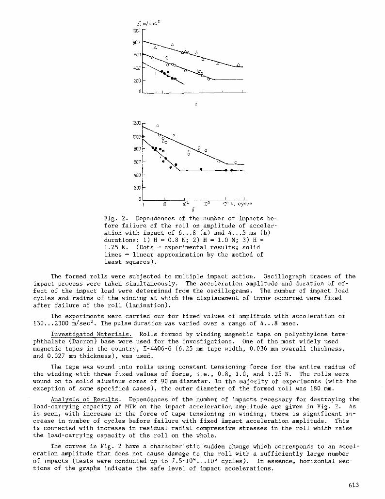
TABLE i. Values of {he Coefficients in Formula (I) for Rolls Wound with Differ- ing Tape Tension
Tape tension- I Impact ing force, N 'duration, msec
Ct C.,
0,8 4 ... 5 937 2;:3 0,8 6 ... 8, 486 176 1,0, 4 ... 5 1137 143 1,0' 6 ... 8 623, 117 Ifi5 6 ... 8 812 ~'2
I 10 10 2 10 3 !0 ~ N,cycles
Fig. 3. Dependence of the number of impact load cycles required for lamination of rolls on the relative radius of winding k for a* = 210 m/see 2
We note the significant effect of the duraction of impacts required for failure of rolls. With 1.5-2 times decrease in duration of impact load application and, correspondingly, decrease in impact energy, the curves of long-term impact strength of MTR are displaced up- ward along the y-axis (Fig. 2). This testifies to increase in number of impacts required for lamination of the rolls. As seen from Fig. 2, the experimental results in the a* ~ log N coordinates (here, a* is amplitude of impact load acceleration; N is number of cycles re- quired for failure of the roll) are quite nicely approximated by straight lines, i.e., the following dependence takes place:
a* = C~ C2lgN. ( 1 )
Values of coefficients C I and C 2 for rolls wound with different tape tensioning forces are iven in Table ].
MTR used in contemporary magnetic recorders are of different geometrical dimensions depending on the structural features and purpose of the given appratus. In this connection, it was found advisable to investigate the effect of roll geometry on load-carrying capacity under the effect of impact loads. For this, experiments were carried out with rolls wound to a relative outer radius of winding k = Ro/R a = 1.70, 1.80, 1.90, and 1.96 (R o is outer radius of winding; R a is radius of core). The rolls were wound with tape tensioning force of 0.8 N and then subjected to impacts of 6.~ msec duration with acceleration amplitude of 2 1 0 m / s e c a .
T h e d e p e n d e n c e o f n u m b e r o f i m p a c t l o a d c y c l e s r e q u i r e d f o r m u t u a l d i s p l a c e m e n t o f t u r n s
on the outer relative radius of the roll is given in Fig. 3. As is seen, there is increase in impact strength of the roll with decrease in its outer radius. This is connected with decrease in the shear stresses which occur in the body of the winding under impact and cause relative shift of turns.
The above graph, constructed in semilogarithmic coordinates k ~ log N, can be approxi- mated by a straight line with accuracy sufficient for practical purposes. The equation of the line is
l g N = 16,85 7,87#.
6 1 4
~r, MPa
-0~6 ~i2 L~
r i @1 i
I
10 ~$2 103 N,cycles
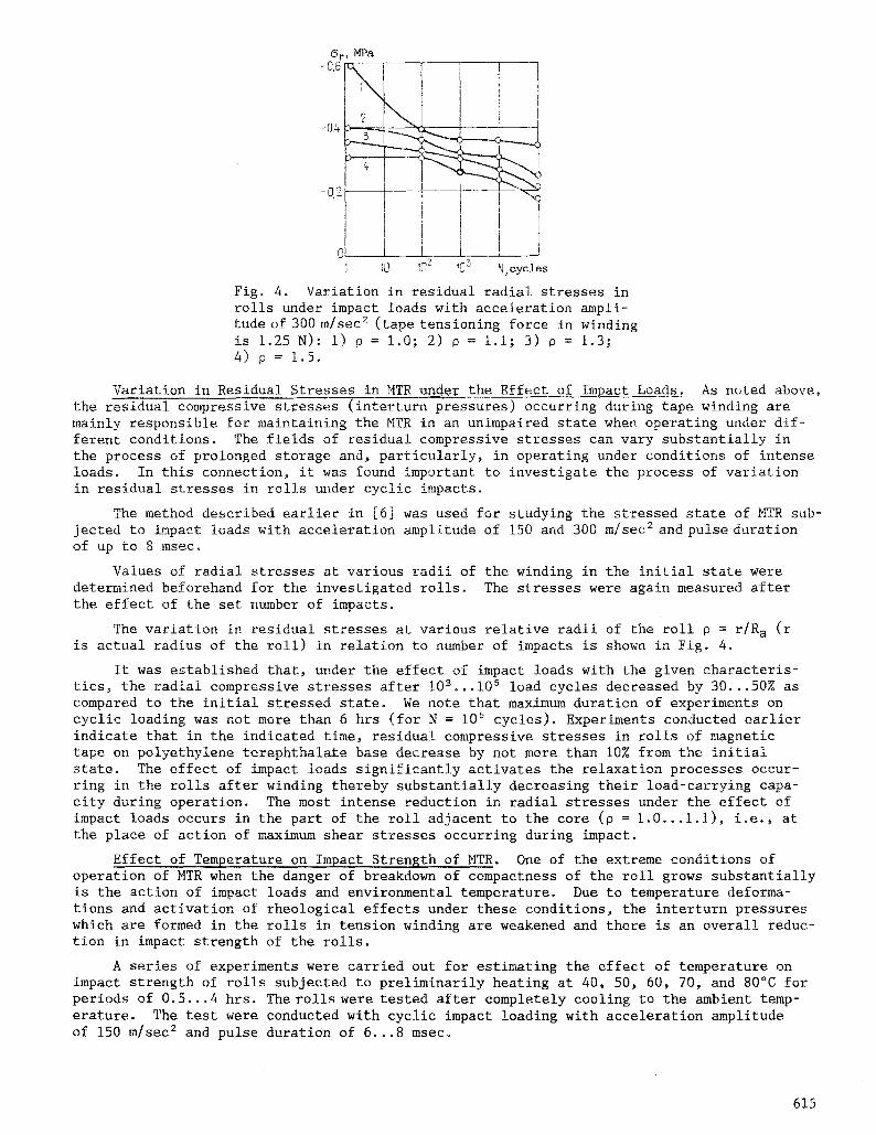
Fig. 4. Variation in residual radial stresses in rolls under impact loads with acceleration ampli- tude of 300 m/sec 2 (tape tensioning force in winding is 1.25 N): i) P = 1.0; 2) P = i.i; 3) P = 1.3; 4) p = 1o5.
Variation in Residual Stresses in MTR under the Effect of Impact Loads. As noted above, the residual compressive stresses (interturn pressures) occurring during tape winding are mainly responsible for maintaining the MTR in an unimpaired state when operating under dif- ferent conditions. The fields of residual compressive stresses can vary substantially in the process of prolonged storage and, particularly, in operating under conditions of intense loads. In this connection, it was found important to investigate the process of variation in residual stresses in rolls under cyclic impacts~
The method described earlier in [6] was used for studying the stressed state of MTR sub- jected to impact loads with acceleration amplitude of 150 and 300 m/sec 2 and pulse duration of up to 8 msec.
Values of radial stresses at various radii of the winding in the initial state were determined beforehand for the investigated rolls. The stresses were again measured after the effect of the set number of impacts.
The variation in residual stresses at various relative radii of the roll p = r/R a (r is actual radius of the roll) in relation to number of impacts is shown in Fig. 4.
It was established that, under the effect of impact loads with the given characteris- tics, the radial compressive stresses after 103...105 load cycles decreased by 30...50% as compared to the initial stressed state. We note that maximum duration of experiments on cyclic loading was not more than 6 hrs (for N = 105 cycles). Experiments conducted earlier indicate that in the indicated time, residual compressive stresses in rolls of magnetic tape on polyethylene terephthala~e base decrease by not more than 10% from the initial state. The effect of impact loads significantly activates the relaxation processes occur- ring in the rolls after winding thereby substantially decreasing their load-carrying capa- city during operation. The most intense reduction in radial stresses under the effect of impact loads occurs in the part of the roll adjacent to the core (p = 1.0...i.i), i.e., at: the place of action of maximum shear stresses occurring during impact.
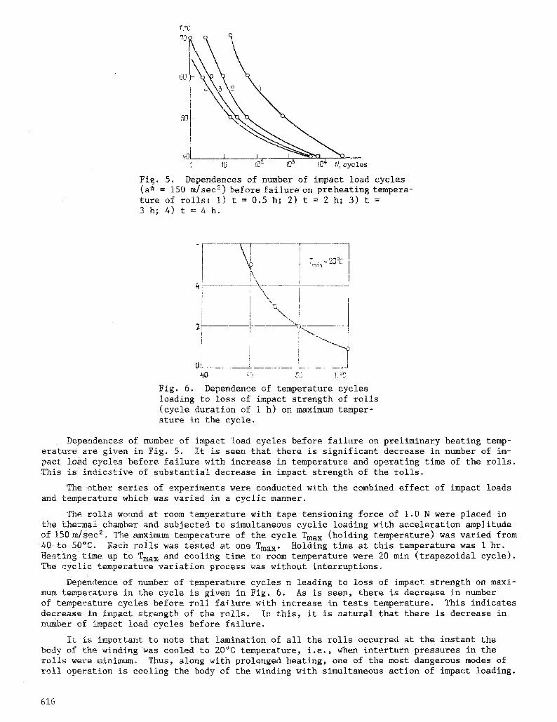
Effect of Temperature on Impact Strength of MTR. One of the extreme conditions of operation of MTR when the danger of breakdown of compactness of the roll grows substantially is the action of impact loads and environmental temperature. Due to temperature deforma- tions and activation of rheological effects under these conditions, the interturn pressures which are formed in the rolls in tension winding are weakened and there is an overall reduc- tion in impact strength of the rolls.
A series of experiments were carried out for estimating the effect of temperature on impact strength of rolls subjected to preliminarily heating at 40, 50, 60, 70, and 80~ for periods of 0.5...4 hrs. The rolls were tested after completely cooling to the ambient temp- erature. The test were conducted with cyclic impact loading with acceleration amplitude of 150 m/sec 2 and pulse duration of 6...8 msec.
615
7 \\c 80 - ~
1 10
I
I0 ? 103 IO S N, cycles
Fi~. 5. Dependences of number of impact load cycles (a* = 150 m/sec 2) before failure on preheating tempera- ture of rolls: I) t = 0.5 h; 2) t = 2 h; 3) t = 3 h; 4) t = 4 h.
i ! \,\
21 i
I
I
OL 55 T ~ i ,
Fig~ 6. Dependence of temperature cycles loading to loss of impact strength of rolls (cycle duration of I h) on maximum temper- ature in the cycle.
Dependences of number of impact load cycles before failure on preliminary heating temp- erature are given in Fig. 5o It is seen that there is significant decrease in number of im- pact load cycles before failure with increase in temperature and operating time of the rolls. This is indicative of substantial decrease in impact strength of the rolls.
The other series of experiments were conducted with the combined effect of impact loads and temperature which was varied in a cyclic manner.
The rolls wound at room temperature with tape tensioning force of 1.0 N were placed in the thermal chmnber and subjected to simultaneous cyclic loading with acceleration amplitude of 150 m/sec=o The amxim~n tea~nperature of the cycle Tma x (holding temperature) was varied from 40 to 50~ Each rolls was tested at one Tma x. Holding time at this temperature was i hr. Heating time up to Tma x and cooling time to room temperature were 20 min (trapezoidal cycle)~ The cyclic temperature variation process was without interruptions.
Dependence of number of temperature cycles n leading to loss of impact strength on maxi- mum temperature in the cycle is given in Fig. 6. As is seen, there is decrease in number of temperature cycles before roll failure with increase in tests temperature. This indicates decrease in impact strength of the rolls~ In this, it is natural that there is decrease in number of impact load cycles before failure.
It is important to note that lamination of all the rolls occurred at the instant the body of the winding was cooled to 20~ temperature, i,e., when interturn pressures in the rolls were minimum, Thus, along with prolonged heating, one of the most dangerous modes of roll operation is cooling the body of the winding with simultaneous action of impact loading.
616

LITERATURE CITED
i. GOST 16962-71, Electronic engineering and electronic items. Mechanical and climatic effects. Requirements and methods of testing, Introduced January i, 1971.
2. V. I. Antonov and L. P. Vodyanitskii, Handbook of Magnetic Recording Techniques [in Russian], Tekhnika, Kiev (1981).
3. V. N. Travnikov, Magnetic Recorder Mechanisms [in Russian], Tekhnika, Kiev (1976). 4. E, S. Umanskii, V. V. Kryuchkov, and N. S. Shidlovskii, "Load-carrying capacity of rolled
~olymer films," Probl. Prochn., No. I0, 104-113 (1980). 5. E.S. Umanskii, V. V. Kryuchkov, and N. S. Shidlovskii, "Toward the evaluation of the
effect of the temperature factor on the load-carrying capacity of a magnetic tape roll," Ibid., No. 8, 62-65 (1981).
6. E. S. Umanskii and N. S. Shidlovskii, "Experimental investigation of residual stresses in magnetic tape rolls," Ibid, No. I0, 43-49 (1983).
7. E. S. Umanskii, N. S. Shidlovskii, and L. L. Stezhko. "Load-carrying capacity of mag- netic tape rolls under vibration loads," Ibid, No. ii, 52-56 (1986).
8. E. S. Umanskii, N. S. Shidlovskii, and L. L. Stezhko~ "The effect of vibration and temp- erature on the load-carrying capacity of magnetic tape rolls," Ibid, No. ii, 69-72 (1986).
617