Embed Size (px)
Citation preview
Aerosmith Fastening Systems | 5621 Dividend Road, Indianapolis, Indiana 46241 | Toll Free Phone: 1.844.373.2666
3-16-20v2Page 1 of 4
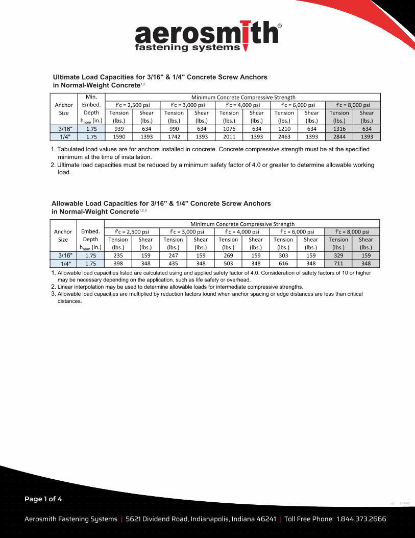
Ultimate Load Capacities for 3/16" & 1/4" Concrete Screw Anchors in Normal-Weight Concrete1,2
Allowable Load Capacities for 3/16" & 1/4" Concrete Screw Anchors in Normal-Weight Concrete1,2,3
Tension
(lbs.)
Shear
(lbs.)
Tension
(lbs.)
Shear
(lbs.)
Tension
(lbs.)
Shear
(lbs.)
Tension
(lbs.)
Shear
(lbs.)
Tension
(lbs.)
Shear
(lbs.)
1.75 939 634 990 634 1076 634 1210 634 1316 634
1/4" 1.75 1590 1393 1742 1393 2011 1393 2463 1393 2844 1393
1. Tabulated load values are for anchors installed in concrete. Concrete compressive strength must be at the specifiedminimum at the time of installation.
2. Ultimate load capacities must be reduced by a minimum safety factor of 4.0 or greater to determine allowable workingload.
Minimum Concrete Compressive StrengthAnchor
Size
Min.
Embed.
Depth
hnom (in.)
f'c = 2,500 psi f'c = 3,000 psi f'c = 4,000 psi f'c = 6,000 psi f'c = 8,000 psi
3/16"
Tension
(lbs.)
Shear
(lbs.)
Tension
(lbs.)
Shear
(lbs.)
Tension
(lbs.)
Shear
(lbs.)
Tension
(lbs.)
Shear
(lbs.)
Tension
(lbs.)
Shear
(lbs.)
1.75 235 159 247 159 269 159 303 159 329 159
1.75 398 348 435 348 503 348 616 348 711 348
1. Allowable load capacities listed are calculated using and applied safety factor of 4.0. Consideration of safety factors of 10 or highermay be necessary depending on the application, such as life safety or overhead.
2. Linear interpolation may be used to determine allowable loads for intermediate compressive strengths.3. Allowable load capacities are multiplied by reduction factors found when anchor spacing or edge distances are less than critical
distances.
Minimum Concrete Compressive StrengthAnchor
Size
Embed.
Depth
hnom (in.)
f'c = 2,500 psi f'c = 3,000 psi f'c = 4,000 psi f'c = 6,000 psi f'c = 8,000 psi
3/16"1/4"
Aerosmith Fastening Systems | 5621 Dividend Road, Indianapolis, Indiana 46241 | Toll Free Phone: 1.844.373.2666
3-16-20v2Page 2 of 4
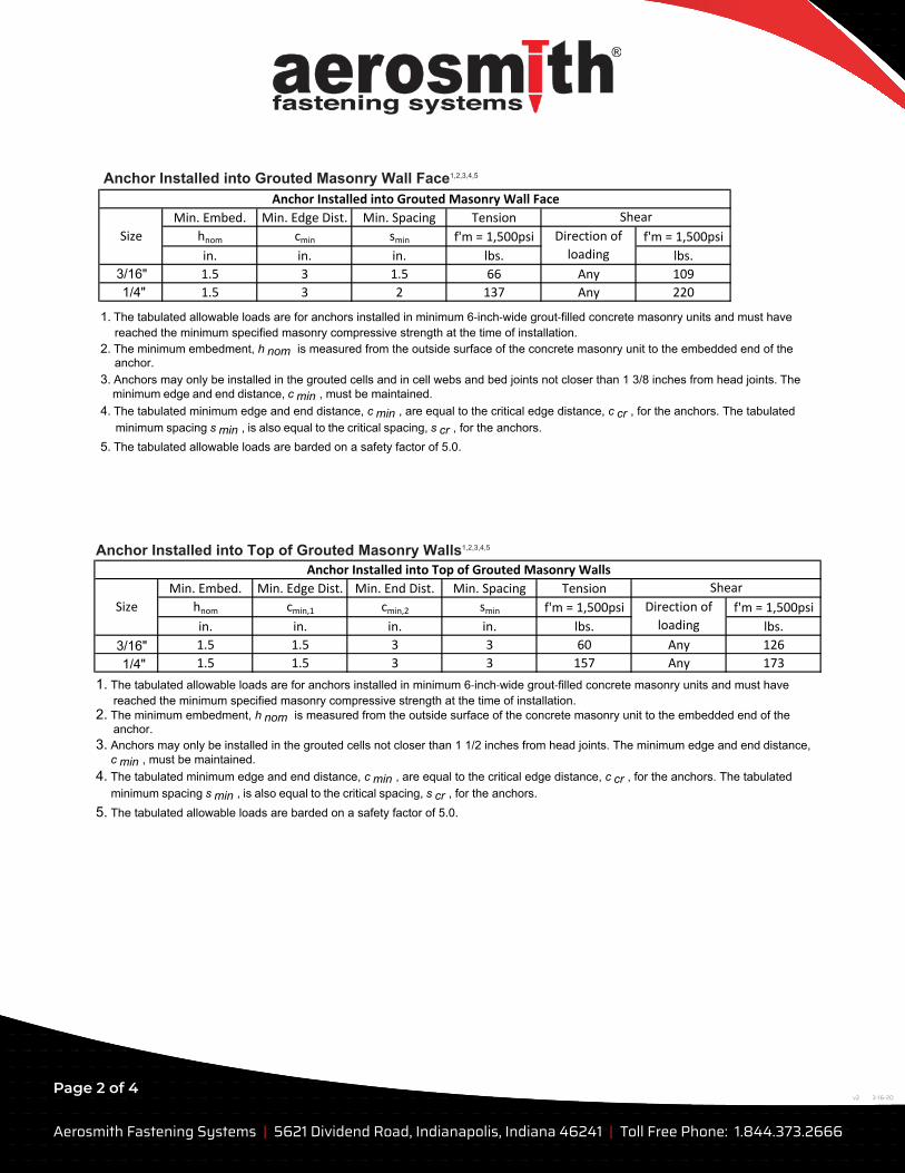
Anchor Installed into Grouted Masonry Wall Face1,2,3,4,5
Anchor Installed into Top of Grouted Masonry Walls1,2,3,4,5
Min. Embed. Min. Edge Dist. Min. Spacing Tension
hnom cmin smin f'm = 1,500psi f'm = 1,500psi
in. in. in. lbs. lbs.
3/16" 1.5 3 1.5 66 Any 109
1/4" 1.5 3 2 137 Any 220
1. The tabulated allowable loads are for anchors installed in minimum 6‐inch‐wide grout‐filled concrete masonry units and must havereached the minimum specified masonry compressive strength at the time of installation.
2. The minimum embedment, h nom is measured from the outside surface of the concrete masonry unit to the embedded end of theanchor.
3. Anchors may only be installed in the grouted cells and in cell webs and bed joints not closer than 1 3/8 inches from head joints. The minimum edge and end distance, c min , must be maintained.
4. The tabulated minimum edge and end distance, c min , are equal to the critical edge distance, c cr , for the anchors. The tabulated minimum spacing s min , is also equal to the critical spacing, s cr , for the anchors.
5. The tabulated allowable loads are barded on a safety factor of 5.0.
Anchor Installed into Grouted Masonry Wall Face
Shear
Direction of
loading
Size
Min. Embed. Min. Edge Dist. Min. End Dist. Min. Spacing Tension
hnom cmin,1 cmin,2 smin f'm = 1,500psi f'm = 1,500psi
in. in. in. in. lbs. lbs.
1.5 1.5 3 3 60 Any 126
1.5 1.5 3 3 157 Any 173
1. The tabulated allowable loads are for anchors installed in minimum 6‐inch‐wide grout‐filled concrete masonry units and must havereached the minimum specified masonry compressive strength at the time of installation.
2. The minimum embedment, h nom is measured from the outside surface of the concrete masonry unit to the embedded end of theanchor.
3. Anchors may only be installed in the grouted cells not closer than 1 1/2 inches from head joints. The minimum edge and end distance, c min , must be maintained.
4. The tabulated minimum edge and end distance, c min , are equal to the critical edge distance, c cr , for the anchors. The tabulated minimum spacing s min , is also equal to the critical spacing, s cr , for the anchors.
5. The tabulated allowable loads are barded on a safety factor of 5.0.
Anchor Installed into Top of Grouted Masonry Walls
Size
Shear
Direction of
loading
3/16"1/4"
Aerosmith Fastening Systems | 5621 Dividend Road, Indianapolis, Indiana 46241 | Toll Free Phone: 1.844.373.2666
3-16-20v2Page 3 of 4
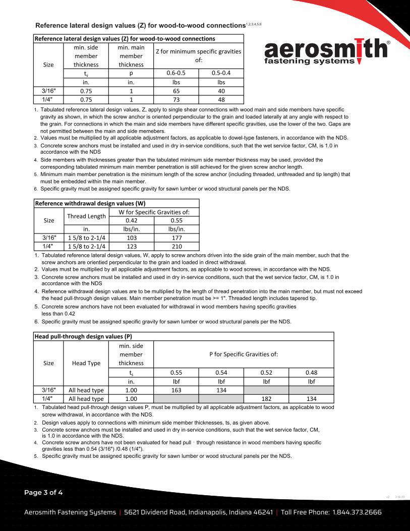
Reference lateral design values (Z) for wood-to-wood connections1,2,3,4,5,6
min. side
member
thickness
min. main
member
thickness
ts p 0.6‐0.5 0.5‐0.4
in. in. lbs lbs
3/16" 0.75 1 65 40
1/4" 0.75 1 73 48
Z for minimum specific gravities
of:Size
Reference lateral design values (Z) for wood‐to‐wood connections
1. Tabulated reference lateral design values, Z, apply to single shear connections with wood main and side members have specificgravity as shown, in which the screw anchor is oriented perpendicular to the grain and loaded laterally at any angle with respect tothe grain. For connections in which the main and side members have different specific gravities, use the lower of the two. Gaps arenot permitted between the main and side memebers.
2. Values must be multiplied by all applicable adjustment factors, as applicable to dowel‐type fasteners, in accordance with the NDS.3. Concrete screw anchors must be installed and used in dry in‐service conditions, such that the wet service factor, CM, is 1.0 in
accordance with the NDS4. Side members with thicknesses greater than the tabulated minimum side member thickness may be used, provided the
corresponding tabulated minimum main member penetration is still achieved for the given screw anchor length.5. Minimum main member penetration is the minimum length of the screw anchor (including threaded, unthreaded and tip length) that
must be embedded within the main member.6. Specific gravity must be assigned specific gravity for sawn lumber or wood structural panels per the NDS.
0.42 0.55
in. lbs/in. lbs/in.
3/16" 1 5/8 to 2‐1/4 103 177
1/4" 1 5/8 to 2‐1/4 123 210
1. Tabulated reference lateral design values, W, apply to screw anchors driven into the side grain of the main member, such that thescrew anchors are orientied perpendicular to the grain and loaded in direct withdrawal.
2. Values must be multiplied by all applicable adjustment factors, as applicable to wood screws, in accordance with the NDS.3. Concrete screw anchors must be installed and used in dry in‐service conditions, such that the wet service factor, CM, is 1.0 in
accordance with the NDS4. Reference withdrawal design values are to be multiplied by the length of thread penetration into the main member, but must not exceed
the head pull‐through design values. Main member penetration must be >= 1". Threaded length includes tapered tip.5. Concrete screw anchors have not been evaluated for withdrawal in wood members having specific gravities
less than 0.426. Specific gravity must be assigned specific gravity for sawn lumber or wood structural panels per the NDS.
Size
W for Specific Gravities of:
Reference withdrawal design values (W)
Thread Length
min. side
member
thickness
ts 0.55 0.54 0.52 0.48
in. lbf lbf lbf lbf
3/16" All head type 1.00 163 134
1/4" All head type 1.00 182 1341. Tabulated head pull‐through design values P, must be multiplied by all applicable adjustment factors, as applicable to wood
screw withdrawal, in accordance with the NDS.2. Design values apply to connections with minimum side member thicknesses, ts, as given above.3. Concrete screw anchors must be installed and used in dry in‐service conditions, such that the wet service factor, CM,
is 1.0 in accordance with the NDS.4. Concrete screw anchors have not been evaluated for head pull‐through resistance in wood members having specific
gravities less than 0.54 (3/16") /0.48 (1/4").5. Specific gravity must be assigned specific gravity for sawn lumber or wood structural panels per the NDS.
P for Specific Gravities of:
Size Head Type
Head pull‐through design values (P)
Aerosmith Fastening Systems | 5621 Dividend Road, Indianapolis, Indiana 46241 | Toll Free Phone: 1.844.373.2666
3-16-20v2Page 4 of 4
3/16" 1/4"in. in.
33
1.75 1.75
1.44 1.85
0.36 0.46
2.16 2.78
1.44 1.85
0.72 0.93
0.36 0.46
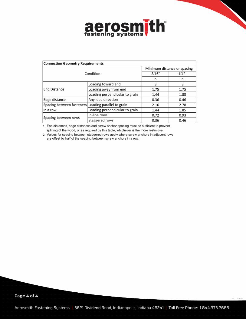
1. End distances, edge distances and screw anchor spacing must be sufficient to preventsplitting of the wood, or as required by this table, whichever is the more restrictive.
2. Values for spacing between staggered rows apply where screw anchors in adjacent rowsare offset by half of the spacing between screw anchors in a row.
Connection Geometry Requirements
Spacing between rowsIn‐line rows
Staggered rows
Minimum distance or spacing
Condition
Edge distance Any load direction
Spacing between fasteners
in a row
Loading parallel to grain
Loading perpendicular to grain
Loading toward end
Loading away from end
Loading perpendicular to grain
End Distance
![FLUID CHILLERS 28 TO 150 TONS - Delta Inddeltaind.net/wp-content/uploads/2019/08/012617_Chase... · 2019. 8. 21. · Tank Capacity [gal] 124 124 124 124 159 159 159 159 159 159 159](https://img.pdfslide.us/doc/110x75/613777b90ad5d2067648a37d/fluid-chillers-28-to-150-tons-delta-2019-8-21-tank-capacity-gal-124-124.jpg)

![Recommendations Resolutions - Login Book.pdf[1.75]2% [1.50]1.75% All other employment under Federation -negotiated Electronic Media Agreements [1.50]1.75% [1.25]1.50% 37 BE IT FURTHER](https://img.pdfslide.us/doc/110x75/5f0fd3e07e708231d44614a9/recommendations-resolutions-login-bookpdf-1752-150175-all-other-employment.jpg)