Embed Size (px)
Citation preview

SUIMARY REPORT
TASK VI SPACE STORABLE PROPELLANT MODULE
'ENVIRONMENTAL CONTROL TECHNOLOGY
17 July 1970
Report No.' 14051-6007-T-00
Lo 041 E N BER) ( R)
I2(NASA CR OR TMX AD NUMBER) (CA-f:ORy)
Reprmduced byNATIONAL TECHNICAL rINFORMATION SERVICE
Springfiolda Va 22151
https://ntrs.nasa.gov/search.jsp?R=19710000567 2020-05-13T03:30:47+00:00Z

SUMMARY REPORT
TASK VI STORABLE PROPELLANT MODULE ENVIRONMENTAL CONTROL TECHNOLOGY
R. E. Deland L. R. Kelley 0. 0. Haroldsen R. N. Porter
14051-6007-TO:-00 ontract NAS 7-750
Jevans er, Heat Transfer and Thermo
dynamics Department
W. R. Wanniund Manager, Engineering Design Laboratory
TRW Systems One Space Park
Redondo Beach, California 90278

TABLE OF CONTENTS
Page SUMMARY vii
1.0 INTRODUC'TION
2.0 THERMAL D1 UIGN 2
2.1 F'LUORINE TANK 3
42,1,1 Heat Capacity
2,,2 Potential Heat Leaks 8
2.2 CONTINGENCY COOLING 14
2,2. Selective Insulation Removal 14
2,2,2 Deployable Radiator 15
2,2.3 Heat Pumps 21
2,2.4 Expendable Frigerant 22
2.3 HI)hAZINE TANK 24
2t3.1 Passive System 28
2,3,2 Semi-Passive System 32 2.4 lIELZUM TANK 34
2.5 GROUNDHOLD THERMAL CONTROL 35
3.0 PROPULSION SYSTEM DESIGN 37
4.0 STRUCTURAL D)ESIGN 40
4.1 STRUCTURAL BASELINE CONFIGURATION 40
4.2 BASELINE CONFIGURATION PLUS HEAT PIPE 40
4.3 FLUORINE TANK SUSPENSION SYSTEMS 46
4.4 DEPLOYABLE RADIATOR 47

TABLE OF CONTENTS (Continued)
Page
5.0 EVALUATION 48
5.1 COMPONENT EVALUATIONS 51
5.1.1 Hydrazine Tank Thermal Control 51
5.1.2 Fluorine Tank Thermal Control 56
5.1.3 Fluorine Tank Support 59
5.1.4 Helium Tank Thermal Control 60
6.0 CONCLUSIONS AND RECOMMENDATIONS 63
7.0 REFERENCES 65

LIST OF FIGURES
Page
2-1 1 Eight Node Analytical Model 10
2-2 Net Heat Input Rate to Fluorine Tank by Direct 13 or R~flected Solar Impingement
2-3 Expected Angle of Solar Incidence 19
2-4 Heat Rejection Rate for a Deployable Radiator 20
2-5 Schematic of Basic Vuilleumier Cryogenic Refrigerator. 23
2-6a - RTG to Hydrazine Tank Thermal Coupling Cohcepts 25
2-6b Hydrazine Tank to Space Thermal Coupling Concepts 26
2-7' Eight Node Thermal Resistance Network for Analyzing 30 - the RTG to Hydrazine Tank Thermal Radiation Coupling
2-8 Equilibruim Temperature of the Hydrazine Tank with 31 Thermal Radiation Coupling to the RTG. Parameter F41 is the View Factor from the Uninsulated Tank Area to the RTG.
2-9 Hydrazine Temperature with a Fully Insulated Tank and 33 Thermal Radiation Coupling to the RTG.
2-10 Weight Trade-off for Conduction Coupling Between the 35 Hydrazine and Helium Tanks
S3-1 Schematic Diagram of the Propulsion System Fluid Circuit 38
DRAWINGS
SK 406961 F2 /N2H4 Propulsion Module, Thermal Baseline 5 Configuration
SK 407042 Fluorine Tank.Insulation/Suspension Systems 7
SK 407046 Deployable Radiator Concept, F2 Tank 16
SK 406922 F2/NaH4 Propulsion Module, Structural Base- 41 line Configuration
-V

LIST OF TABLES
2-1 Therjnal Conductance of Various Fluorine Tank Support Systems
- Page
-8
2-2 Thermal Conductance of Plumbing Lines into the Fluorine Tank 9
2-3 Net Heat Rate into Fluorine Tank Due to Thermal Radiation (Shield in Place)
11
2-4 Net Heat Rate in Fluorine Tank Due to Thermal Radiation (Shield Removed)
11
2-5 Incremental Heat Rejection Capability Gained by Totally Removing Foam Insulation from the Outboard Half of the Fluorine Tank Surface Area
14
3-1 Propulsion System Design Guidelines 39
4-1 Summary of Estimated Subsystem Weights (Baseline Configurations) 42
4-2 Summary of Estimated Subsystem Weight Differences for Various Modifications from Baseline
44
4-3 Comparison of Estimated Weights for Various Propulsion Module Configurations
45
5-1 Relative Evaluation Factors for Acceptable Hydrazine Tank Thermal 55 Control Combinations
"5-2 Relative Evaluation Factors for Acceptable Fluorine Tank Thermal Control Combinations
-58
5-3 Relative Evaluation 'actors for Acceptable Fluorine Tank Support Configurations
59
5-4 Relative Evaluation Factors for Acceptable Helium Tank Thermal Control Concepts
61
5-5 Summary of Thermal Control Concept Evaluations for the Major Components of the F2/N 2H4 Propulsion Module
62
-vi

SUMMARY
The objective of Task VI was to identify and briefly investigate possi
ble thermal control concepts for a Fa/ N2H4 (fluorine/hydrazine) propul
sion module- Preliminary thermal structural, and propulsion analyses have
been conducted which indicate that all major requirements (long term in
flight storage, no F2 venting, and no frost or condensation build up during
ground hold) can be accomplished with a baseline design system weight
-(including propellants) of-approximately 3406 pounds. This is 67 pounds
heavier than the similar OF2 /B2H 6 system studied under tasks II and III.
Propellant weight (which increased by 96 pounds) is responsible for the
weight increment.
From a thermal requirements point of viev, the major difference between
the current F2/N2H 4 system and the previous OF2 /B2H6 system is that the two
propellants for the current system must be stored at widely different tem
peratures (fluorine < 200'R, hydrazine 490 - 560'R), whereas with the pre
vious system, both propellants could be stored at approximately 2500 R.
Because of the large temperature gradient, the low fluorine temperature,
and the no vent requirement, the RTG has been repositioned out of view of
the fluorine tank, boron filament support tubes have been replaced on the
fluorine tank by lower conductance epoxy fiberglass tubes, flat plate radi
ation shields have been placed between taiks, and solar impingement on the
fluorine tank, its support struts and plumbing lines has been restricted
to short periods (t < 10 days). Preliminary calculations show that under
these conditions, passive radiation from the insulated fluorine tank to
space can maintain the fluorine at an equilibrium temperature of approximately
1000 R (with a hydrazine temperature of 5300R). Heat capacity of the fluo-
rine and its tank would then provide a maximum margin of safety in the event
of inadvertent heat leaks or solar impingement.
-vii

Calculations also show that the addition of only 24 to 38 Btu/hr (de
pending on insulation thickness) raises the fluorine equilibrium tempera
ture to the maximum acceptable limit for firing (2000R). Since the equi
librium temperature is this sensitive to heat leaks and since it is uncer
tain at this time whether or not direct and reflected solar impingements
can be sufficiently limited, four auxiliary techniques have been considered
briefly for providing contingency cooling. Of these four techniques (in
flight removal of insulation, a deployable radiator, a heat pump, or an
expendable cryogen), only two (the second and third) appear to be poten
tially effective enough to justify further consideration, and both of
these require considerable development and impose certain weight penalties.
It is, therefore, recommended that more detailed analytical model(s) of
the basic passive system for controlling the fluorine temperature be creaied
during Task VII so as to establish heat paths and solar impingpment limits
more accurately.
Preliminary analysis has identified at least seven different, accep
table combinations of components for thermal control of the hydrazine tank.
Of these seven, four are recommended for further study based on a systematic
relative evaluation procedure. Three of the recommended systems are passive
and utilize thermal radiation, a heat pipe, or a solid aluminum bar to
couple the hydrazine tank to the RTG. The fourth system is semi-passive
and utilizes a louvered panel to couple the tank to the RTG.' All of the
recommended'systems use passive radiation from the insulated surface as the
main coupling between .the hydrazine tank and space.
-viii

1.0 INTRODUCTION
This is the Task VI summary report of the Space Storable Propulsion
Module Environmental Control Technology Project accomplished under Con
tract NAS 7-750. Task VI had as its objective to identify and briefly
-investigate possible thermal control concepts for a F2/N2H4 (fluorine/
hydrazine) propulsion module. The concepts are to be-analyzed more fully
under Task VII.
Operational requirements for the F2/NZH module are similar to those4
described in the Task I summary report(1) for the OF2 /B2H6 module, except
storage temperatures are significantly different. Some of the groundhold
cooling and frost prevention concepts described and analyzed in the summary
reports(2),(3) for Tasks II and III are, however, applicable to the fluo
rine tank of the present module. An attempt has been made to utilize as
much of the previous work as possible and limit the discussions in the
present report to problems not common with the previous system.
Section 2 discusses the principal differences in thermal control re
quirements between the present (F2/N2H4) and the previous (OF2 /B2H6) pro
pulsion module designs and identifies several possible concepts for ther
-mally coupling the RTG, hydrazine tank, fluorine tank, and helium pressurant
tank to each other and t9 space. Sections 3 and 4 discuss the resulting
differences in the propulsion and structural designs, respectively. Sub
jective evaluations of variois concepts are discussed, and relative rating
factors are assigned in Section 5. Conclusions and recommendations are
presented in Section 6.

'2.0 THERMAL DESIGN
An F2 /N2H4 propulsion module may present somewhat more difficult ther
mal control problems than the previous OF2 /B2H6 module. The main difference
is that tr4 fluorine must be stored at a colder temperature (<2000R*) and
the hydrazine at a warmer temperature (490-5600 R) than the previous propel
•lants (250 0R). The wide difference in temperature makes thermal isolation
of the fluorine tank (from the hydrazine tank, from the RTG, and from the
sun) extremely critical. The temperature of the hydrazine and helium tanks
can be controlled quite easily by balancing heat input from the RTG with
heat rejection to space. Rejection of absorbed heat from the fluorine tank
to space, however, is much more difficult because of fluorine's low storage
temperature.
Groundhold requirements and considerations are essentially the same as
for the OF/B2H6 propulsion module systems studied under tasks II and III,
except that only one of the tanks (fluorine) now needs to be cooled with
auxiliary equipment to prevent boil-off and insulated with closed cell foam
to prevent frost build up.
In light of the groundhold and flight requirements, the thermal base
line design that has been considered is to insulate the entire surface area
of the fluorine tank with at least 3/4 inch of sprayed-on closed-cell foam.
A single layer of 3 mil second surface silvered Teflon is bonded to the outer
surface of the foam to provide a high emittance but low (and u.v. stable) solar
absorptance. The hydrazine tank is placed between the RTG and the fluorine
tank and its entire surface is insulated with multilayer aluminized Mylar.
Heat is conducted from the deployed RTG to the hydrazine tank by a system
of two heat pipes or two solid aluminum bars and a woven wire coupled flexible
joint. In order to provide a low emittance surface capable of withstanding
the high temperature that would occur during solar impingement, several outer
layers of insulation on the hydrazine tank are aluminized Kapton (rather
than Mylar) with the aluminized side facing outward, The helium pressurant
.tank is insulated in the same way (with multilayer aluminized Mylar and
Kapton) and is thermally "clamped" to the hydrazine tank by means of a heat
Liquid, subcooled 200F below saturation temperature at 300 psia.
-2

pipe or solid aluminum bar. Fiat plate radiation shields (.020-inch alumi
num), placed between the fluorine and hydrazine tanks and between the fluo
rine and helium tanks, minimize radiant coupling. All support struts'for
* the fluorine tank are epoxy-impregnated fiberglass, tubes. These tubes and
any plumbing or instrumentation leads from the fluorine tank are to be insu
lated in the same way as the tank itself so that the total net heat leakage
into the fluorine is minimized.
'Calculations indicate that in the absence of solar impingement, this 'system would result in a fluorine tank temperature of about 1000R*. Draw
ing SK406961 (2 sheets) shows the thermal baseline configuration layout that
has been considered. Special features of and possible modifications for
each tank are discussed in the following subsections.
2.1 FLUORINE TANK
The basic approach is to thermally isolate the fluorine tank as well
as possible from all heat sources, and then rely on the heat capacity of the
'fluorineand the tank to absorb the bulk of any short term inadvertent heat
input due to direct or reflected solar impingement.
This approachdiffers from that used with the 0F2/B2H6 module in that no louvers are used on the T2 tank. The main reason for this change is
that the fluorine must be stored at a lower temperature than either OF2 or B2H6, and at this lower temperature,-louvers would provide little control.
Elimination of louvers on the fluorine tank is a major simplification, be
cuase it eliminates the problem of how to insulate the louvers against
frost buildup on the.ground but provide efficient radiation in space. An
important factor in being able to maintain the fluorine temperature between limits without louvers is that the fluorine tank is thermally isolated and
most of the heat leakage that does occur comes from the warm hydrazine tank
which is maintained between rather narrow temperature limits.
The system should be designed so that the F2 tank is in equilibrium at or near its lower temperature limit because residual or unintentional heat leaks will most likely be larger than anticipated rather than smaller. A -bias of this type will provide maximum pad in case of inadvertent solar impingement.
-3

2.1.1 Heat Capacity
The estimated inflight heat capacity is based on the following
assumptions,,
(1) Fluorine and its tank are initially at a temperature just above
the freezing temperature of fluorine (100'R).
(2) 1800 pounds of fluorine are to be stored for 1793 days.
(3) No fluorine is vented and none is used for mid-course maneuvers.
-(4) Temperature of the fluorine and its tank can be allowed to rise
to 2000R.
Total heat that can be absorbed by the fluorine then is:
Qfluorine WFCP (T - Ti) (1800)(.363)(200-100)e F
Qflu~rine 67,300. Btu
Total heat that can be absorbed by the fluorine tank is
Qtank = WTCP (Tt - Ti) (59.6)(;25)(200-100)
= Qtank 1530. Btu
The total net heat leakage that can be absorbed by heat capacitance this is:
Qtotal - 67,300 + 1530 - 68,830 Btu.
-4

16 15 14 13 12
UVEWh
- ua-t IA010EXCAXXIZ\
-- - -
,~vIS.W A-A
IMt
N
• ~~~ ~ IN 7U FVEW
5 ./
is 14 13 12
FOLDOUT FRAME
16

21 1-" 0 9 so 7
.7Z.0
T.HICKCK IN020.IO
4o.5
--.
-
INSULXC~hlmom
REU\AT,
INSIKki~t
I--
lavIn S L]C 10- - I I-P
.
10
t A$SULWQTIOW
T,s "\ L ,
-MVT4ThD1 -zA~mH cQ
04CMLIE AiXN
I
UIfZD 'i& .
F1RAPIEGM SUOsU
-llls
VTALVE
7
-
'"AL V A LVE -
FRAME2
J10987-a
FOLDOUT FRAMEJ
1211

6 -5- - - - 4 - -T -- - - - 'T -
-
2 RZQD 'Lit4 7AV ASS4OI'
EN am
-- AtLkI'NasD
-
VA
SUL&TIOM(.1o IHIC<)-LMNIE YUR.
4UESLAVLRS At tSflfzE b oz .
t~.Sn'4- .S F
0A.5NVY VE
o 0 - - ~~-oso A~S
- +z
tN~oflD
S g E.
I.LV VALVE 4-- PA
it7
5
s-
PG
3 JA
VbX.QU VALVE

__ __ __ __
H
RTG
F
F/
/ .
II o|C -s
N.
00~
B FODU it
_ _ _ _ _ _ _ _ _ _ _ _ _ _ _ --
A
FoLDO UTFAME 1.

-- ---
-
WJSUiCr-- - -H
(".'muM% .01T-- -
ts' " I "-TAK
7- 7
rP4Jt ~Q '! ~ FEKI~E 'OIN
F. TAR
--.".',,,., PAIGE 6
I WIT PPE98 AlE -F, N,
FOLDOUT FRAME a ....

__________
I'
____________ _______-________ -_____________________,/ "'I
8 7 6
-ITYPE 5.
l|o.O
B ~W
FOLDOUT FRAME A
0 NOTES UNLESS OTHERWSE 5K1

E A 4-4
.!r.
• : " " " "PAGE 7. BIviEw A-A
m)TUu~w (&T-ThR5IO I T R[ I JPARTS Lll
T 1R4M 3
FOLDOUT FRAME ,.

I"/
Table 2-1 shows that the Type 1 support system (see Drawing SK 407042) has
the lowest thermal conductance. With that system, an end-to-end temperature
difference of, say, 1000F on the struts will result in a heat leak of 0.613 Btu/hr.
The type 2 sppport system which is shown in Section 4.0 to be more practical,
has approximately twice this much thermal conductance.
Plumbing to the fluorine tank consists at present of three stainless
steel lines. One of these is a 0.75 inch (nominal) inner diameter, 1.14 inch
(nominal) outer diameter convoluted stainless steel flex-hose with a wall
thickness of 0.013 inch for transporting propellant approximately 38 inches
to the rocket engine. Another is a 1/4 inch (nominal) O.D., 0.016 inch wall
-thickness pressurant line running approximately 40 inches to the pressurant
valve panel. The third is a 1/2 inch aomina O.D. 0.16 inch wall thickness
line running approximately 28 inches to the pressure relief valve. Estimated
end-to-end thermal conductances for these three potential heat flow paths are
given below in Table 2-2. Cooling coil lines and instrumentation wires were also
considered but deemed to be ne$14ible cqupared to thoqe repre~ented in Table 2-2.
TABLE 2-2. THERMAL CONDUCTANCES OF.THE
PLUMBING LINES INTO THE FLUORINE TANK
NOMINAL DIAMETER WALL THICKNESS EFFECTIVE LENGTH CONDUCTANCE*
LINE (inches)' (inches) (inches) (Btu/hrt F)
Propellant .95 .013 76 .000425
Pressurant .25 .016 40 .000240
Relief .50 .016 28 .000750
Includes a slight amount of conductance due to gase6us helium conduction (K = .07 Btu/hr ft OF) within each tube.
It can be seen that if the lines are well insulated along their length, they
will not present any-major heat leak problem even if the valve blocks at the
far end are several hundred degrees warmer than the fluorine tank. Another potential heat leak is thermal radiation from the hydrazine
tank. An eight-node analytical model as shown in Figure 2-1 was used to
make a preliminary evaluation of this heat path.
-9

7
Q Fluorine Tank
a Outer Surface of Foam Insulation
6 u e rhlydrazine Tank
@Outer Surface of Multilayer Insulatloi
0 _uter Surface of Multilayer Insulatio
0Outer surface of Foam Insulation - QRadiation Shield , E = .05
-"Space (00R)
Simulated Spacecraft (Blockage)
Simulated Meteorite Shield (Blockage)
0R-
F 246 1 2 7 4 3 5
Multilayer Insulation (K/L = .01 Btu/hr ft2 OF)
Foam Insulation (KC= .00625 Btn/br ft OF) Simulated Spacecraft (Blockage) (E= .8)
FIGURE 2-1. EIGHT NODE AN~ALYTICAL MODEL
.-10

The Figure 2-1 network has been solved for various fixed values of fluorine
tank temperature (Ti) and various thicknesses of foam insulation (K = .00625
Btu/ft hr OF). The tesulting net heat rate (q = q6-1 + q2-1) into the fluo
rine tank is presented in Table 2-3. Table 2-4 gives the corresponding
results with the radiation shield removed. Negative values of q indicate a
net heat loss (to space) by the fluorine tank.
A comparison of Tables 2-3 and 2-4 indicates that'insertion of a flat
plate radiation shield between the tanks is an effective means of reducing
heat input to the fluorine tank, especially at lower fluorine tank tempera
tures. With the shield in place, the equilibrium temperature (net q = 0)
is approximately 1000R regardless of insulation thickness.
TABLE 2-S. NET HEAT i.RATE INTO FLUORIN Ak DETO THERMAL RADIATIONt
(Intertank Radfation Shield in Plade)
INSULATION THICKNESS 0.75 1.5 3.0(Inches) +
Fluorine Tank Temp., (TI) q q q (*R) (Btu/hr) (Btu/hr) (Btu/hr)
200 -37.43 -31.35 -24.45
100 0 + 0.03 + 0.10
0 + 2.74 + 2.74 + 2.74
Hydrazine Tank Temperature = 70F, incident solar flux = 0.
TABLE 2-4. NET HEAT RATE INTO FLUORINE TANK DUE TO .... (Intertank Radiation Shield Removed)HERALRADIATIONt
INSULATION THICKNESS 07 . . (Inches) I
Fluorine Tank Temp., (TI) q q q (OR) (Btu/hr) (Btu/hr)" (Btu/ hr)
200 -19.25 -15.90 -12.33
100 +39.50 +18.45 +12.70
0 +43,10 +43.20 +42.40.
= tHvdrazine Tank Temperature - 70OF, incident solar flux 0.

Thus, heat must be added in order to maintain any temperature above 100 0R.
A heat rate of only 24 to 38 Btu/hr (depending on insulation thickness)
will cause the equilibrium temperature to rise to the upper limit for
firing (200'R). A simplified transient analysis indicates that this tem
-perature rise would require 4 to 6 months (90% response).
The final potential source of heat input to the fluorine tank that ha.
been considered is direct or reflected solar impingement. This was done by
simply applying various amounts of heating to Node 6 (outer surface of the
foam insulation) on the existing 8-node analytical model and re-evaluating
the net heat rate into Node-l (the fluorine tank). The results are plotted
in Figure 2-2. It is seen that increasing the thickness of the foam insu
lation will significantly reduce the effect of solar impingement. Even
with three inches of foam, however, solar impingement must be avoided or
restricted to short periods. For example, suppose one solar constant
(G 430 Btu/ft 2 hr) impinges at right angle (8= 900). The projected area
(A ) of the fluorine tank for a side-looking sun is approximately 12 ft2 . If the outer surface of the insulation were covered with one layer of second
surface silvered Teflon (for minimum and stable as/ 1H), the surface would
absorb the following heat rate:
GAs cos e = (430)(12)(.1)(1) = 515..Btu/hr
Figure 2-2 shows that with three inches of-foam insulation, this surface
heat rate would result in a net heat input rate of about 70 Btu/hr to the
fluorine tank. An insulation thickness of 3/4 inch would increase the net
heat input rate to about 220 Btu/hr. Based on the previously estimated heat
capacity, the latter rate could be sustained for approximately ten days before
the upper temperature limit for firing would be exceeded.
To summarize the fluorine tank calculations, it has been shown that con
duction type heat leaks due to tank supports and plumbing lines are relatively
small compared to heat inputs due to thermal radiation. Radiation input
from the hydrazine and helium tanks can be suppressed by flat plate
radiation shields to achieve an equilibrium temperature of approximately 1000 R
in the absence of solar impingement. Maximum solar impingement with a side
looking sun can be sustained for approximately ten days without exceeding
the 2000R fluorine temperature limit for firing.
-12
--
400 III Foa -a
i . I I I IThi 1 6
L 0.7'
300
200 0 :3
0
4j
o0. 100
0
-40 10 100 '1000
Absorbed Solar Heat Rate at Insulation Surfdce, GA a Cos 0,(Btu/hr)~ps
FIGURE 2-2. NET HEAT INPUT RATE TO FLUORINE TANK DUE TO DIRECT OR REFLECTED SOLAR IMPINGEMENT.
(THERMAL CONDUCTIVITY (K) OF THE FOAM - 0.00625 Btu/ft hr OF.)

2.2 CONTINGENCY COOLING OF FLUORINE TANK
Four methods have been considered for increasing the heat rejection
rate from the fluorine tank in the event, that inadvertent beat leaks from
the sun, the RTG, the hydrazine tank, the 'heliumtank, the rocket engine,
or the electronics package should cause the fluorine temperature to rise
above the maximum desired temperature (2000 R). These methods are discussed
separately in the following subsections to provide a basis of comparison.
2.2.1 Selective Insulation Removal
During groundhold and the first few hours of flight, the entire sur
face of the fluorine tank must remain thermally insulated to prevent frost
and planetary heating, respectively. Once the S/C leaves the vicinity of
Earth, however, heat removal from the fluorine tank could be increased by
removing insulation from those areas of the tank surface that are shaded
from the sun but have a substantial view of space. This could include per
haps as much as one half of the total surface area of the tank or about 22
square feet. The previously described 8-node analytical model was therefore
used to estimate how much benefit could be derived by removing the out
board half (Node 6) of the foam insulation. Table 2-5 shows the resulting
heat rejection rate increase due to total removal of three different ini
tial thicknesses of insulation.
TABLE 2-5. INCEMENTAL HEAT REJECTION CAPABILITY GAINED BY TOTALLY REMOVING FOAM INSULATION FROM THE OUTBOARD HALF OF THE FLUORINE TANK SURFACE AREAt
INSULATION THICKNESS 0.75 1.5 3.0 (Inches)
Fluorine Tank Temp. (TI) Aq Aq Aq (0 R) (Btu/hr) (Btu/hr) (Btu/hr)
200 9.83 15".03 20.63
100 0.09 0.17 0.30
tBare tank surface is assumed to have the'same emittance as the
foam insulation,(cH= 0.8).
-14

It is quite clear from Table 2-5 that removing insulation from the
fluorine tank does not "buy" a great amount of heat rejection capability
at the low temperatures required. In addition, removing the insulation
makes avoidance of solar impingement all the more critical.
Due to practical considerations, insulation removal would probably
have to be an irreversible process. Thus, it would not be initiated unless
the fluorine temperature was approaching its upper limit. Even then, remo
val might best be done progressively (perhaps 1/3 of the area at a time) so
that the terminal temperature at time of burn would not be too cold.
Admittedly-, there are some practical problems involved in designing
removable foam insulation. 'There is little doubt, however,- that it could
be done with negator springs using pyrotechnic or electromechanical release.
The entire spring and release assembly would be beneath the insulation to
avoid local heat leakage.
2.2.2 Deployable Radiator
A deployable radiator could be used as either an alternative or supple
ment to the removable insulation approach. Drawing SK 407046 is a conceptual
drawing of one type of deployable radiator that has been considered. This
particular design consists of several overlapping radiator panels that are
spring-loaded to unfold by side rotation (like a carpenter's folding rule)
to form a long rectangular radiator. Each joint is designed to provide easy
rotation during deployment but to lock solidly for low thermal resistance
after deployment. Because of the need for low thermal resistance and weight,
cryogenic heat pipes are imbedded within honeycomb panels to form the indi
vidual radiator sections..'
The thermal heat paths for a deployable radiator of this type can be
drawn schematically as follows.
-15
H 0onsycome. IIAT PIPV S 4"~alSTmhCTOwr- 2- 2qD
N +
-Y G$.
DETIL?RIG AZrkTF P,%D1 z SCALE11
~ ~~ ~ FRM-O N SOHW~ kFOLDOUT~~ C 6

4. 3 2.
ftclh
.~ 24 . TY?
VOR A4sY ;f:TO 5-aI
-EN I.FSI TOTypA
BM.LLOCK SPR~kNC L0ADNO E~
~~V0Th AY' RRfIAIR SOWE
COIJCPT,MND~ ~ ~ .RADIXTOR ~ ~ ~ ~ ~ ~ .LCS~S ~ ~ ~ Pato,.-~--Rf~~T~DLY4NT Se4~tE~4CNG MCAA~l~MRD~k4C~407.T04ro
I4~~~AT 119E2TOr5Tt

Stub
RI e#
fluorine V2
(2000R)
Z Panel #3
(add similar resistors for additional panels)
where:
RI = heat pipe resistance per section
R{2 = joint resistance per section
q = rate of heat removal from fluorine tank.
EH =.hemispherical emittance of the radiator (0.9)
A = radiator area (single side) per section (6 ft2 )
Preliminary calculations indicate that a 1/2-inch diameter heat pipe with a
.010-inch thkck saturated wick, an 18-inch long evaporation section, and an
.18-inch long condensing section would impose a thermal resistance (R1) of
about 0.03'F hr/Btu. Two such pipes each attached to separate 25 mil face
sheets and overlapping each other co-linearly by 18 inches as shown below
would produce a joint resistance (R2) of approximately 0.250 F hr/Btu.
-17

Btu h 25 hr OF ft2
Thus, with only one heat pipe per radiator section, the total resistance
(RI =-R2) per section would be 0.280 F hrIBtu. With two parallel heat pipes
per section, total resistance (R1 + R) would drop to 0.140F hr/Btu.
An important problem with the deployable radiator is that the radiating
surface(s) must be protected (by shades or insulation) from solar--irradiance.
Ideally, the deployable radiator should be positioned in the spacecraft shadow
and edgewise to the sun and should be allowed to radiate from both sides as
shown schematically in Figure 2-3. In this position, however, regular off
pointing angle variations (plotted in Figure- 2-3) and random ± 5 degree
pointing angle uncertainty (parallel to the plane of the paper) would result
in exposing the radiator surface to shallow angle solar irradiance at least
part of the time. Even if the radiating surface(s) were covered with a'low
a./el coating, such as second surface silvered Teflon, the resulting absorbed
solar flux would be unacceptably large (46.2 Btu/hr per panel for only 5
degrees misalignment). To avoid this fate, overhanging edge shades could be
added to each panel, but this introduces serious mechanical problems during
deployment and reduces the panel view factor to space. A better alternative
might therefore be to pitch the deployable radiator 5 or 100 so that the sun
never impinges on one side and insulate the sunward side. Figure 2-4 shows
the heat rejection rate that can be achieved with typical resistances for
a one-sided deployable radiator of this type as a function of the number of
radiator panels. Each panel would weigh approximately .5 pounds based on
r18r

olar Vector
0L2'Off-Pointing(!DI
Angle _
Undefined Spacecraft y
I
E- - lectronics Package
'ID F2
Deployable Radiator
°LO1 '''' ''1g " "
" '"4" M I," I-1 1"
q
0 -- Tim- f20om L
-A FU 2---3 XE OFSLRNI C- --HH1 -
100
0iefo
P14E23
20 30 0
XECE
anh
NL
0
Dy
FSOA
0
NIEC
0 0 0

•
100
80
Emittance, F = 0.9
Solar Flux, G = 0
4;
c4 60 Ri + R2 0.14
(Two heat pipes - per panel)
.)U,
40
~per
RI + R2 0.28 -(Single heat pipe
panel)
to20' 40
"'0 2 Number of
4 2'3'
6 Radiator• Panels,
8 Ne
10
FIGURE 2-4. HEAT REJECTIONg RATE FOR A DEPLOYABLE RADIATOR
-20

25 mil aluminum facesheets on both sides. It can be seen that for the
particular design considered, the point of "diminishing returns" is reached
atapproximately the fourth to sixth panel.
The main point to be made here is that at least one method of deploy
ing a space radiator appears to be practical and to have some merit as a
means of cooling the fluorine tank. Other deployment schemes such as a
flexible roll-out or a laterally hinged fold-out or a telescopic slide-out
radiator might prove to be superior to the model discussed here.
2.23 Heat Pumps
Four types of heat pumps have been considered for possible use in
moving heat from the fluorine tank to a warmer radiator from which it could
then be more easily rejected to space. With the possible exception of the
Vuilleumier cycle, none appears suitable. A brief discussion of the four
types and the reasons why they are unsuitable follows.
Vapor Compression Cycle
Vapor compression cycles require mechanical work to turn the
compressor and such work is not available in the present applica
tion. In addition, it is doubtful whether the required low tempera
tures could be achieved by vapor compression even with a cascade
system.
Absorption System
Absorption systems use heat as the driving force rather than
mechanical work. A refrigerant is alternately absorbed and then
liberated by the absorbant. The RTG as presently designed, operates
at 960R and radiates approximately 10,000 watts of heat to space.
This heat in principle could be used to drive an absorption type re
frigerator or heat pump. Unfortunately, all of the presently known
absorption systems require gravity for operation, and most of them
use either water-ammonia or lithium bromide-water as the absorbant
refrigerant combination. Thus for the present appoication, a wicking
system would have to be developed so as to replace hydrostatic pres
sure due to gravity with capillary pressure. An absorbant-refrigerant
combination would have to be found that would allow the cycle to work
at the desired low temperature.
-21

Solid State Cooling
Thermoelectric elements are at present limited by practical
considerations to temperatures above 2300R(4). In addition, they
require a prohibitive amount of electical power (200 watts to
achieve less than 1 watt of refrigeration at 2340R(4)).
Vuilleumier Cycle
The Vuilleumier Cycle is the most promising of the heat pump
methods investigated. It is a heat driven refrigeration cycle that
is independent of gravity. An experimental model has delivered 5
watts of refrigeration at 1350R(S). That particular model weighed
only 18 pounds and required approximately 480 watts of heat from a
14600R source ( s). The refrigerator described in Reference 5 consists
of two different sized displacers (pistons) operating at 90 degrees
*to each other on a common crankshaft pin as shown in Figure 2-5.
While pressure differentials are small and rotational speed is low,
the fact that moving parts are involved would probably-make this
system unsuitable for full time use because of the long life require
ment. It could perhaps be used intermittently (say, once every six
months) to compensate for unexpected heat leakages into the fluorine
tank.
AiResearch Manufacturing Company (Torrance, California) is presently
developing a Vuilleumier engine which does not have any moving parts. How
7ever, the efficiency of that engine is considerably reduced, and the devel
opment work is approximately three years from completion.
2.2.4 Expendable Frigerant
This method involves storing another cryogenic fluid for venting
through a heat exchanger within the fluorine tank. Required properties
for the frigerant are:
(1) Non-corrosive to spacecraft materials so that venting
can be tolerated
(2) High heat of vaporization
(3) High weight density
(4) Boiling temperature near the maximum fluorine storage temperature
-22

Gas-Filled P Working Volume L(Typically Helium
at High Pressure) Heat Exchanger
Absorbs Heat from Load at Low
Coolig-ZTemperatureCooling
Cylinder
" Cooling
Dis- C
placer rHeat Exchanger j Reject Heat
to Ambient Heat Exchanger
Absorbs Heat Regeneraor from Heat Source
-- 0 Displacer
Power Cylinder
Crankcase- crank Trowsourc of Heat at High Temperature ("10000 F)
Figure 2-5. Schematic of Basic Vuilleumier
Cryogenic Refrigerator
-23

Methane (CHOj appears to be a relatively attractive candidate. It boils
(atmospheric pressure) at 201.40R, absorbs 219.2 Btu/lb. as it boils, and
weighs approximately 26.46 lb./ft 3 (as a liquid). It can easily be seen
that a large weight penalty must be accepted in order to achieve any sit
nificant~amount of cooling by this method. For example, to simply match
the 68,830 Btu that can be absorbed by the fluorine and its tank would
require:
Wmethaneh 66,830 314. lbs.219.2=
Some additional cooling could be achieved by subcooling the methane to the
fluorine freezing point (970 R) before launch. This would place the methane
approximately 66.50 F below its own freezing point so that the heat of fusion
(25,2 Btu/lb.) could be utilized along with the normal heat capacity asso
ciated with temperature rise first as a solid and then as a liquid. The
314 pounds of methane could absorb approximately another 12,000 Btu in
this way. Dividing the total heat that can be absorbed by 314 pounds of
methane by the total storage time (42,600 hours) gives the average heat leak
age rate that could be accomodated by the expendable frigerant.
68,830 + 12,000 1.9 Btu/hr.42,600
2,3 HYDRAZINE TANK
Thermal control of the hydrazine tank is accomplished by shielding the
tank as much as possible from the varying solar flux (430 Btu/fft 2 hr at Earth,
16 Btu/ft 2 hr at-Jupiter) and then balancing heat input from the RTG with
thermal radiation to space. This is the same basic approach that was used on
the OF2/B2H module studied under Tasks I, II, and III. However, due to the
higher storage temperature of the hydrazine, several alternate methods of
transporting heat have been reconsidered. Figure 2-6a shows the most promis
ing passive and semi-passive concepts for transporting heat from the RTG to
the hydrazine tank,while Figure 2-6b shows three passive and semi-passive
methods of rejecting heat from the hydrazine tank to space. Detailed
analyses have not been performed for any of these concepts; that will be done
-24

THERMAL RADIATION (To the Insulation)
.: ->-.........
N2N4
THERMAL- RADIATION RADIATION.THERMALTTo an Uninsulated (To a Louvered Area)(To an Uninsulated
Area)
.......I.
. .....t
N2 N4 .2N 4
CONTROLLED THERMAL CONDUCTIONTHERMAL CONDUCTION(anexptMcnil
(Solid Bars or Heat Pipes Thaea Swiet Mchaded)l with Woven Wire Flex- Thra wthadd
joint)0
PASSIVE CONCEPTS CONCEPTS.SEMI-PASSIVE
FIGURE 2-6a. CONCEPTS FOR TRANSPORTING HEAT FROM THE RTG TO THE "HYDRAZINE TANK
-25

N2H N2H4N2H4
Thermal Radiation from Thermal Radiation from Thermal Padiation from Fully Insulated Tank an Uninsulated Area a Louvered Area
(passive) (passive) (Semi-Passive)
FIGURE 2-6b. HYDRAZINE TANK TO SPACE THERMAL COUPLING CONCEPTS

under Task VII. Based on a simple "voltage divider" network, however, it
would appear that a purely passive means of thermal control would requira
that the RTG temperature not vary more then about twice the allowable vari
ance in hydrazine temperature. To see why this is true, consider the fol
lowing diagram upon which the nominal temperatures are indicated.
T RTG 960 0R RIR G
Ri
TN2H 5250 R11
R2
space
where:
R = overall equivalent thermal resistance between the
RTG and the hydrazine tank
R2 = verall equivalent thermal resistance between'the hydrazine tank and space
The resistances R1 and R2 can be considered linear over small ranges of tem
perature change so that by proportion:
TR2 T2-i]
N2H RitRa TRG[
Differentiating both sides gives:
dTN R dT E2-2]RRIG

By solving equation [2-1] for R2/(RI+R2) and substituting the result into
equation [2-2), one obtains NdTN2 E4
Nz - TRTG RTG [2-3]
or numerically:
'AN2H4 2 AA MTAT [2-4]
Thus if the hydrazine tank must be held to 5250 R ± 250 R, a purely passive
system cannot be used unless the RTG temperature is approximately 960°R ± 50CR
.under all conditiois.
2.3.1 Passive Systems
Present thinking is that if a purely passive system can be used, the
conduction coupling concept between the RTG and the hydrazine tank may be
best because of its high degree of predictability and testability. Another
major advantage with conduction coupling,for this particular application
is that the heat input to the hydrazine tank can then be made quite inde
.pendent of whether or not the RTG is in'the stowed or the deployed position.
Let us assume for the moment that the helium tank is thermally "clamped"
ta the hydrazine tank and the entire surface area of both tanks (=62.4 ft2)
is insulated with multilayer aluminized film (KIL = .01 Btu/ft2 hr 9F):
Assume also that the outer several layers are Kapton with the aluminized side
out (ec .05) so that neither tank receives significant heat input by ther
mal radiation from the RTG. Then, if the insulated tanks have an overall
view factor to space of, say, 0.75 and the inside temperature is nominal
(525 0R), the emitted flux to space would be'approximately 88 Btu/hr. This
is the heat rate that must be transported from the RTG to the hydrazine tank
by the conduction bar in order to maintain thermal equilibrium under the
assumed conditions. The combined thermal resistance required for the con
duction bar, the flex-joint, and the end interfaces is thus:
960 r525 OF hrS 88 5.94 Bi
-28

An allowance of approximately 1 VF hr/Bu should be adequate for the
end interfaces and a-short woven wire flex strap. This would leave 4.940F hr/Btu
for the conduction bars. Sheet two of drawing SK 406961 shows the total length
of the two conduction bars to be approximately 5 feet. Solution of the steady
state one-dimensional heat flow equation shows that if the bars were made of
1100 aluminum (K = 128 Btu/ft hr OF), the required cross sectional area would
then be:
= 8 9 = .0115 ft2 A =5 KR (128) (4.94)
2or: A 1.66 in
For a circular cross section, this translates into a bar diameter of about
1.45 inches. Total weight for 5 feet of 1.45-inch diameter aluminum bar is
approximately 10 pounds A thermally equivalent heat pipe system using 5 feet of
1/2-inch diameter stainless steel tubing with 35 milwall thickness would
weigh approximately 1 pound.
A purely passive system utilizing thermal radiation rather than con
udction as the coupling agent between the RTG and the hydrazine tank has
been briefly examined using the eight node analytical model shown in Fig
ure 2-7. The model was run repeatedly each time varying either the unin
sulated tank area (A4) or the view factor (F41, from the uninsulated area
to the RTG) to obtain the results plotted in Figure 2-8. For convenience,
it was arbitrarily assumed that the view Factor F21 from the insulated area
(Node Z) to the RIG was equal to F4i. This is not a necessary condition,
but it could be easily achieved if desired. It can be seen in Figure 2-8
that for a given view factor, varying the amount of uninsulated area has
little effect on the equilibrium temperature of the hydrazine unless the
exposed area falls below approximately.four square feet. The reason for
this is that the total heat rate radiated to space by the tank is dominated
by the uninsulated area if that krea is on the order of four square feet or
greater. Thus, doubling the exposed area under this condition doubles not
only the heat input rate from the RTG but also the heat rejection rate to
space, With less than about four square feet of exposed area, radiation
-29

(e6 - .05)
(Uninsulated Area, c4 - .9)
Nz H4 C F
Fj -
K Btu T hr 0
RTG (960"R)(a
.05 -Sa
NzH4'
0f
Shield
K> 'Btu
hr o'
ft
F2 (150'R)
C 8
Space (0*R)
FIGURE 2-7. EIGHT NODE THERMAL RESISTANCE NETWORK FOR ANALYZING THE RTG TO HYDRAZINE TANK THERMAL RADIATION COUPLING

800
o
F41= 0.30
0g25
0.25
-600.15
° * m , t cceptanc Band ]"- - ¢ ,4
E4 40 40
= 0.105
r
50,
20C
0 ~~ 2 05 62
Uninsulated Area of Hydrazine Tank (ft2 )
FIGURE 2-8. EQUILIBRIUM TEMPERATURE OF THE HYDRAZINE TANK WITH THERMAL RADIATION COUPLING TO THE RTG. PARAM TER F41I ISTHE VIEW FACTOR FROM THE
UNINSULATED TANK AREA TO THE RTG.
-31

from the large insulated area accounts for a large part of the total heat
rejection rate to space so that a change in exposed area still has a sig
nificant effect on the heat input rate but not on the heat rejection rate.
The important conclusion that can be drawn'from Figure 2-8 then is that in
the absence of solar impingement on the uninsulated area and with a stable
9600 R RTG temperature, the hydrazine equilibrium temperature can be passively
maintained within the required limits (500 - 5500 R) by providing approximately
four square feet of uninsulated area with this area having a view factor to
the RTG of approximately 0.1.
Since a fully insulated tank offers maximum protection against inadver
tent solar impingement, some of the data (for A = 0) from Figure 2-8 has been
cross-plotted in Figure 2-9 to show more clearly how the hydrazine equili
brium temperature is related to the view factor (F21) for a fully insulated
tank. It can be seen from Figure 2-9 that a view factor 'of approximately 0.6
would be required in order to maintain the nominal hydrazine equilibrium tem
perature with only thermal radiation-coupling and a fully insulated tank, If
the RTG and the hydrazine tank are characterized as parallel cylinders of
infinite length and zero separation (external tangential contact) with respec
tive diameters of 10 and 34 inches, the maximum possible view factor F2 1 from
half the tank (Node 2) to the RTG is approximately 0.15. Radiation coupling
between the RTG and the hydrazine tank is therefore an unworkable concept if
the hydrazine tank is. fully insulated.
2.3.2 Semi-Passive Systems
If variable resistance is required in order to maintain the hydrazine
tank within temperature limits, the advantages of the conduction coupling con
cept are not as clear cut. For one thing, thermal switches are not as well
developed as louvers, so if conduction coupling were used it would probably
be used in the same manner as described previously for a purely passive sys
tem but with a louver system added as shown in Figure 2-6b to provide variable
emittance to space. The thought occurs, therefore, that if a.louver system is
to be used, it may as well face toward the RTG as shown in the upper right
hand corner of Figure 2-6a to provide variable thermal radiation coupling and
-thus eliminate the need for conduction coupling.
-32

600,
Acceptance Band . " . ; ' -'";" ;- ';< . .. . " ' ''"' "..- %.' °7 21'<-. . > .r ' .t> $.... - .. .. ... "-<. .....
*-00
/4
'.
300
View Factor, F21I
FIGURE 2-9. HYDRAZINE TEMPERATURE WITH A FULLY INSULATED TANK
AND THERMAL RADIATION COUPLING TO THE RT.

Since varying the louver opening is in effect the same as varying the
uninsulated area, some insight into how well this system might work can
be obtained by retonsidering Figure 2-8, which is based on a constant emit
tance of 0.9. Note that with a view factor (F41 ) of 0.15, the hydrazine
equilibrium temperature can be changed from the upper acceptance limit
to the lower acceptance limit by reducing the uninsulated area from ap
proximately two square feet to approximately one square foot. In other
words, an area (or effective emittance) ratio of only 1:1 can produce 50'F
or more change in temperature under the realistic conditions assumed.
Louvers (with inward facing blades for solar rejection) can currently
achieve effective emittance variation between 0.13 and 0.72.for an open-to
closed ratio of abour 5:1. It would appear, therefore, that a 2- to 3-square
foot panel of louvers with a view factor to the RTG of Q.15 could provide
significant compensation for any uncertainty or variance in the RTG tempera
ture, solar impingement, or insulation effectiveness.
2.4 HELIUM TANK
Current thinking is that from a'thermal point of view the helium pres
surant gas 6hould be stored at a temperature somewhere near that.of the
hotter propellant (hydrazine). The reasoning is that if the helium'were
stored at or near the cold propellant temperature (1000 R - 2000R), the
expansion that would occur after the cold helium is injected into the warm
tank might cause over-pressurization. Therefore, it is felt that the helium
tank should be thermally close-coupled to the warm hydrazine tank. Sinice
both tanks are to be insulated against radiation to space, the inter-tank
coupling will piobably have to be done by conduction. In the case of the
previous OF2 /B2 H6 module, conduction coupling was provided by a light weight
aluminum beam. However, the higher fuel tank temperature required for the
present F2 /N H4 module will increase the heat loss rate to space and thus
will require lower resistance coupling for a given temperature difference
between tanks. Figure 2-10 shows a plot of the estimated helium tank equi
librium temperature as a function of conductor weight based on an assumed
path length of 2 feet, a hydrazine tank temperature of 5300 R, and an insu
lated helium tank (K/L = .01 Btu/hr 'F ft , e = .05, FHespa=e 0.5). __
-34
550... .. ...Hydr zine Tan T mne auII
500 -- HaPi
(Estimated)
4 50z
SSolid Bar (1100 Alum.)
E400
E4 350
30030
2500.1 1.0 10.
Conductor Weight (lbs.)
FIGURE 2-10. WEIGHT TRADE-OFF FOR CONDUCTION COUPLING BETWEEN THE HYDRAZINE AND HELIUM TANKS
- It is doubtful at present whether there is any significant penalty
in allowing the helium tank tb remain at A temperature of, say, 400R. If that is true, then it can be seen from Figure 2-10 that a heat pipe coup
ling system offers less than 1 pound weight advantage over solid conduction
for this particular coupling application. Because of tank weight and size
considerations, it would be advantageous to store the helium at a lower temperature, such as 180'R. This can be accommodated with a high resistance
thermal coupling, but the increased RC time constant would make thermal
control much more difficult, particularly if solar impingement occurs on
the helium tank.
2,5 GROUNDHOLD THERMAL CONTROL
All of the comments made prior to this point have dealt with flight thermal control. There is, of course, the problem of keeping the fluorine
cold during the'groundhold phase. In addition, as intimated in the comments concerning the ability to accommodate sun heating, it may be highly desir
,able to launch with the fluorine in a highly subcooled siate (approximately
1000 R).
-35

Because of the lower temperatures of fluorine, it is impractical or
impossible to use LN2 as the coolant, as can be done in the case of 0F2 /B2H2 ,
unless the liquid nitrogen is substantially subcooled or is reduced in tem
perature by lowering its pressure. From a practical point of view, both of
these methods of .lowering.the temperature of LN2 are impractical. This leads
to the conclusion that either cooled helium or hydrogen must be used as the
coolant. From a safety point of view, it is not wise to attempt circulating
hydrogen directly inside the fluorine tank. Therefore, helium should be the
coolant and the helium could be cooled either by an external helium cryostat
or a helium/LH2 heat exchanger.
,.Based upon calculations performed during Task 1l (3) the normal heat
transfer to the fluorine tank during groundhold can be expected to be approxiz
mately 4,000 Btu/ir. To compensate for this heating, approximately 80 lbs/hr
of helium at 40°R would be required as the coolant. Assuming the helium is
cooled by LH2 , 4 ft3 /hr of liquid hydrogen would be vaporized.
- An internal cooling coil similar to that used in the OF2/B2H6 module
would be required, but in this case, the length of the coil would have-to be
substantially larger because of the lower film coefficient between the cool
ant and the tube wall and because of the lower temperature differential be
tween the coolant and the propellant. Based upon the analysis reported in
Task III, this coil would have to be approximately'100 ft. in length in order
to reduce the fluorine temperature to 100*R. This is mechanically feasible
and does not add a prohibitive amount of weight.
The main problem encountered in cooling the fluorine during groundhold
may be that of preventing the coolant from picking up substantial quantities
of heat in the line run from the coolant heat exchanger to the propellant
tank. There is no doubt that this line would have to be vacuum jacketed.
The thermal baseline design doesOne additional point should be noted.
not include any louvers. For groundhold thermal control, this is an advan
tage, since removable louver insulation is not required.
-367

3.0 PROPULSION SYSTEM DESIGN
The propulsion system is comprised of three types of equipment:
engine,.-tanks, and plumbing. In compliance with customer direction, little
attention has been given the engine configuration. The engine shown in the
layout is the same as for the OF2/B2H 6 module except for the addition of a
helium heat exchanger. Table 3-1 summarizes the propulsion system design
guidelines.
- Boron filament-wound tankage with 10-mil thick aluminum liners are
showri in the layout. These are sized for an internal volume of 1.1 times
the volume of 1808 pounds of fluorine at 180'R. Keeping both tanks equal
in volume (per the Work Statement) provides over 28% ullage in the fuel tank, which would allow the mid-course fiiings to be made in a blowdown mode if
so desired. The baseline helium tank is~sized to-contain 36 pounds of
helium gas at 4,000"psia and 1800 R. An eccentricity of approximately 0.784
was maintained in all the spheroidal elements of the tankage.
Figure 3-1 is the schematic diagram of the baseline overall propulsion
system fluid circuit. Since the previous version, there have been two
changes made. . A check valve has been inserted in the hydrazine tank pressur
ization -line to prevent hydrazine from entering the heat exchanger. This
is necessary to eliminate the potential hazard of explosive decomposition
of hydrazine in the heat exchanger when it gets hot after engine shutdown.
Two bleed valves have been added just upstream of the propellant valves on
the engine so that the feedlines may be cleaned and passivated. Mass esti
mates in this report reflect these changes.
Component parts are represented in the layout by blocks for each case
where a JPL-approved design is lacking. Component locations ar similar
or the same as those shown for the OF2/B2H6 SSPM. A panel mounted beside
the tank contains the helium squib valves, the filter, regulator and sole
noid-operated helium valves. Propellant tank vent and relief valves are
located on small panels adjacent to the tops of the respective propellant
tanks. Below each tank near the outlets are clusters of components consist-
ing of the fill, isolation, return relief and check valves, plus the filters.
-37

CHECK VALVE
N.O. SQUIB VALVE0G N.C. SOUIB VALVE
- ORIFICE
B2-WAY SOLENOID VALVE'
E-J> FILL VALVE WITH CAP
d
F
[l] [
FILTER
REGULATOR
RUPTURE DISC
RELIEF VALVE
3-WAY SOLENOID VALVE
N H4 F2
FIGURE 3-I. SCHEMATIC DIAGRAM OF F2 /NzH4 SPACECRAFT PROPULSION SYSTEM
-38
Mixture ratio trimming orifices are located-at the propellant valve Inlet
port flanges where the flexible (convoluted metal hose) feedlines attach
to the valves.
Tubing runs are all assumed to be type 321 stainless steel with butt
welded joints. With this construction, very high quality joints can be
made with wall thickness down to 0.016 inch or less. Helium flow rates are
low enough to permit the use of 1/4-inch nominal tubing based on keeping
the steady state Mach number below 0.1. For the high pressure section up
stream of the regulator, a wall of -0.028 inch is adequate, and downstream
all of the tubing could be 0.016 inch. Fill and vent line sizes have been
arbitrarily set at 1/2-inch nominal size. Engine feedlines of 3/4-inch
nominal size result in fluorine flow velocities below 8 ft/sec and hydra
zine velocities below 6 ft/sec (assuming reasonable wall thicknesses and
tolerences). If 12-inch feedlines were used, the velocities would be
below 20 ft/sec and 15 ft/sec, respectively.
TABLE 3-1. PROPULSION SYSTEM DESIGN GUIDELINES
-.Mixture Ratio 2.0
<Chamber Pressure 100 psid
I SP385 -
Thrust 1,000 ibf Propellant Temperature Limits
Fuel ,F-530
5303
Oxidizer 155 ± 25-55 R
Pressurant Helium
Pressurant Initial Pressure 4,000 psia @ 180'R
Propellant and Helium Tanks Boron filament-wound
with 0.010 aluminum liner
-Propellant tank volumes (equal volumes) 1.1 x propellant volume
Propellant Tank pressure 300 psia
Oxidizer mass 1,735 + 73 (residuals) lbm Fuel mass --984 + 37 (residuals)-lbm
Pressurant mass 36 lb @ 155 0R m
-39

4.0 STRUCTURAL DESIGN
4.1 STRUCTURAL BASE LINE CONFIGURATION
The initial design utilizes an arrangement of c6mponents and structure
is similar to the one utilized for the OF2 /B2H 6 system described in the
Tank II report. This is referred to as the structural baseline configuration
and is shown by drawing SK 406922. Structural members have been moved to
the-extent necessary to accomodate the different propellant and pressurant
tank sizis and to account for the center of gravity change dictated by the
change in relative propellant weights. As for the previous design, the C.G.
of the propellants is located along the centerline of the spacecraft so that
under nominal conditions, no lateral CQG. shift will occuw as propellants
are consumed. Structural materials are the same as in the Task II design
with the exception of the transverse beam that supports the three tanks.
*Whereas the entire beam was aluminum to provide thermal coupling between the
tanks, it is now made in two parts. The section that -connects the N2fH tank
and the pressurant tank is aluminum to provide goodthermal conduction be
tween those tanks, while titanium is used between the F2 tank and pressurant
tank to minimize heat transfer between them.
The loads in each structural member were calculated and the required
sue determined in order to obtain a reliable weight estimate.. Table 4-1
presents a weight breakdown for the baseline .design. Weight differences
for possible modifications (discussed below) are given in Table 4-2. An over
all weight comparison for several configurations is then made in Table 4-3.
4.2 BASELINE CONFIGURATION PLUS HEAT PIPE
This concept utilizes a heat pipe to transfer heat from the RTG to the
N21H tank as shown by drawing SK 406961. The RTG is shown in a relocated
position on the N2H4 tank side of the spacecraft to prevent heat radiation
to the F2 tank. Although the heat pipe installation shown assumes an RIG
deployment arrangement that is actually undefined at present, it would appear
that the system has sufficient design flexibility to be adaptable to any
other arrangement without imposing severe constraints.
-40

16 15 14 13
HJ
UC=UtAWVM
A1.
E~~ N 7C. (
00.RE
VvwA-A K
16 15 14 13
FOLDOUT FRAME

_ _
lee S"-!O-1 I m ' ;cz~~~ *~i tTGx . _ _ _ _
I~~o~)a* V~~zf
-. 1 MEI5 -ST-CURI-NUktt ~M l
-- X 0 9tIU1NIO8
FODU FRAME

hPQ ME WLZ INW TO
aa - -+ E1ATEOMO
/0~ N ca/0cs
0scTMrUBSX
1.-
W 0
.IN
~ ~
-Fu~ss
4
UN twk
~V
- rk.NK
I
C-S
7 ~~
, ~~M
~ F'j.CMIGOTL
Uc to,N-I-ji.
DO~
~~bA~~I QI-LtO
IIIWLAW FRAM

TABLE 4-1. SUMMARY OF ESTIMATED SUBSYSTEM WEIGHTS
(BASELINE CONFIGURATION)
-Tankage .1-Helium Tank @ 74.3 lb. ea. 74.30 lb 2-Propellant Tanks @ 54.13 lb ea. .108.26 lb I-Propellant Surface Tension Screens
@ 2,'0 lb ea. 2.0 lb 18-4.-5-6--b
Liquid Circuits 2-Fill Valves @ 1 lb ea. 2.0 lb 1-Solenoid Valves @ 2 lb ea. 2.0 lb 2-Filters @ 1 lb ea. 2.0 Ib -2-Relief Modules @ 1.2 lb ea. 2,4 lb 2-Check Valves @ 1.0 lb ea. 2,0 lb 3-PR Explosive Valves @ 3 lb ea. 9.0 lb
19 -.4 lb
Gas Circuit 1-Fill Valve @ 1 lb ea. 1,0 lb 4-PR. Explosive Valves @ 3 lb ea. 12.0 lb 1-Filter @ 1 lb ea. 1.0 lb 1-Regulator @ 2 lb ea. 2.0 lb 1-Check Valve @ 0.5 lb ea. 0.5 lb 2-Relief Modules (Disc Plus Valve)'@ Ilb ea. 2.0 lb 2-Pressurization & Vent Valves @ 2 lb ea.' 4.0 lb 2-Solenoid Valves @ 2 lb. ea. , 4.0 lb
26.5 lb
Thrust Chamber A 2-Propellant Valves @ 5.0 ea. 10.0 lb
2-Orifice Assys, W/Flanges @ .5,ea. 1.0 lb 2-Bleed Valves @ 1 lb ea. 2.0 lb 1-Thrust Chamber W/Gimbal Mounts 43.0 lb 2-Gimbal Actuators @ 2.25 ea. 4.5 .lb
Fluids Oxidizer (F2)- '1800.0 lb Fuel (N2H4) .1100.0 lb
Helium (He) 36.0 lb
-4362-E
-42

---
TABLE 4-1 (Continued)
Structure-Above Separation Plane
Upper Truss Members' 19.61 lb Tank Upper Support Members 1.44 lb Spacecraft Attachment Fittings 4.25 lb Platform Members (Frame) 8.90 lb Platform Fittings 5.25 lb Engine Support Truss Members 1.28 lb Engine Support Platform 2.75 lb Tank End Fittings -2.70 lb Valve Assy Brackets 6.76 lb Meteoroid Shields 14.32 lb
Structure-Below Separation Plane
Truss Members 45,42 lb Fittings (Separation) 2.50 1b Stabilizing Frame 1.00 lb
...48.92 lb
Miscellaneous
Lines and Fittings 20.0 lb Instrumentation 4.0 lb Command and Squib Harness 8.0 lb Contingency 16.0 -lb
Insulation
Aluminized Mylar (N2H4 Tank) .91 lb Foam (F2 Tank) 4.64 lb .Aluminized Mylar (He Tank) .,401b 'Aluminized Mylar (Alum. Beam) .05 lb .Foam (Ti Beam) -.29 lb Cooling Coil Assy (F2 Tank) 1,25 lb Louvers (N2 H4 Tank) 2.25 lb-
Radiation Shield (F2 Tank) 4.80 lb 14.59 lb
-43
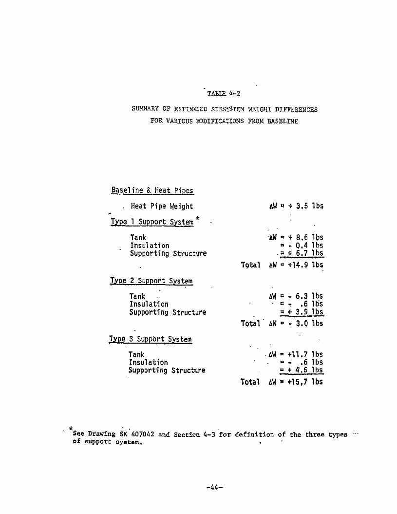
TABLE- 4-2
SUMMfARY OF ESTDJCED SUBSriTEM WEIGHT DIFFERENCES
FOR VARIOUS ODIFICAf-"QNS FROM BASELINE
Baseline & Heat Pipes
Heat Pipe Weight AW + 3.5 lbs
Type I Support System
Tank AW = 8.6 lbs Insulation - Q.4lbs Supporting Structure . + 6.7 lbs
Total 4W = +14.9 lbs
Type 2 Support System
Tank AW = -6.3 lbs Insulation = .6 lbs Supporting.Structare + 3.9 lbs
Total AW = - 3.0 lbs
Type 3 Suppbrt System
Tank . W +11.7 lbs Insulation - .6lbs Supporting Structzre =+ 4.6 lbs
Total AW * +15,7 lbs
See Drawing SK'407042 and Sectif 4-3 for definition of the three types of support system.
-44

TABLE 4-3
COMPARISON OF ESTIMATED WEIGHTS
FOR VARIOUS PROPULSION MODULE CONFIGURATIONS
System Stage Mass * Total ** Weight Fraction Weight
-Baseline 3356.9 ,831 3405.8 (SK 406922)
Baseline and - -Heat Pipe 3360.4 :.830 3409.3 (SK 406961)
Type 1 Support 3371.8 .828 3420,7 (SK 407042)
Type 2 Support 3353.9 ..832 3402.8 -(SK 407042)
Type,3 Support 3372.6 .,828 34!.S (SK 407042)
* Based on 2791 lbs. of burned propellant
•* Includes weight below separation plane
-45

4.3- F2 TANK SUSPENSION SYSTEMS.
Three different .support systems were investigated for the F2 tank in
order to provide better thermal isolation from the supporting structure.
These are sk6wn in Drawing SK 407042 (Section 2.1.2) as Type 1, Type 2 and
Type 3. Each of these systems provide support for the lower end of the tank
by utilizing truss members extending to the frame in lieu of the direct
attachment to the support beam incorporated in the baseline design. The
truss members are glass filament-epoxy tubes used to reduce the heat trans
fer but at the expense of increased weight.
In each case, the tank configuration is altered by shortening its
length and as a consequence increasing the diameter to maintain the same
volume. This of course requires a change in the spacing and size of other
structural members to accomodate the larger diameter and increased spacing
between tank centerlines. Layouts of this modified structure have not been
made, but ir'appears that no problems will be encoutered in accomplishing
-the change. One other minor change is shown on the drawing associated with
the upper tank support. This consists of using a pair of tubes in place of
one of the truss members used to support the-tank" By attaching each of
these tubes at the periphery of the tank boss, a truss is created to resist
any torsional loads that result from the dynamic environment to which the
tank is subjected;
Type land Type 3 systems support the-F 2 tank by means of a 4-member
truss with the apex directly beneath the tank and attached to the frame.
In order to accomodate the greater member lengths, the tanks are shortened
and modified to incorporate four attachment points at tangential locations
around the periphery. This type of attachment almost certainly precludes
the use of boron-epoxy as a tank material due to the difficulty of incor
porating structurally sound joints for the fittings into the wrap. As a
consequence, the tanks will be somewhat heavier and an estimate of the in
crease in weight, considering the use of titanium is included in the summary
of weights. The difference between Type 1 and Type 3 is basically the shape
of the tank that is used to obtain different support member lengths,. f
-46

course, this difference also dictates a complete change in structural mem
bar locations throughout the module. As previously stated, a layout of
these new locations has not been made. However, the effect on weight has
been estimated and is shown in the weight summary.
Type 2 arrangement maintains a polar tank support but requires a short
ening of the tank to provide space for installing a tubular truss between
the tank boss and the frame. In this configuration, the apex of the three
truss members is located at the tank attachment. One member is vertical
and carries loads in the thrust direction directly to the frame. The two
other members attach to the frame at side panel points and serve to carry
lateral loads. With this system, the tank can be of boron-epoxy construc
tion and, although the larger diameter causes some change in location of
other structural members, the degree of change is small. The estimated
change in weight from the base-ine configuration is shown in the weight
summary.
4.4 DEPLOYABLE RADIATOR
Drawing SK 407046 shows a concept for a deployable radiator that is
thermally coupled to the F2 tank by means of a heat pipe. Each panel of
the radiator is of honeycomb construction, and the stowed panels are se
quentially deployed by torsion springs. Although no detailed analysis has
been performed, the concept is structurally feasible. During the boost phase
of flight, the stowed panels can be well supported while being subjected to
the high load environment. After deployment, the only significant loading
is that resulting from engine firing. These loads would be in the order
of 1/2 g, and the panels can easily be made to withstand loads of this
magnitude.
-47

5. EVALUATION
The foregoing preliminary investigation has been directed toward dis
crete potential problem areas which combine to form the Overall thermal
control design problem for an Fz/N 2Hl propulsion module, The discrete areas
of concern are:
a RTG/hydrazine coupling
* Hydrazine/space coupling
* Helium/hydrazine coupling
* Fluorine/hydrazine decoupling
* - Fluorine/space.coupling
o Fluorine/frame decoupling
In order to properly evaluate the various thermal control concepts that
have been identified and considered for possible application tothese key--
areas of concern, it is necessary to consider the concepts as part of an
integrated thermal control subsystem which will be exposed to a variety of
environmental conditions. The concepts can be grouped according to the major
thermally important sections of the propulsion module as follows:
-0 Hydrazine Tank Control
1. Fully Insulated, (passive) f (passive){Alone, 2. Uninsulated Area toward RTG, with Louvers to Space, (semi-passive
3. Louvered Panel Toward RTC, (semi-passive)
4. Heat Pipe to RTOC fAlone, (passive) Jwith Thermal Switch, (semi-passive)
5. Conduction Bar to RTC with Louvers to Space, (semi-passive)
* Fluorine Tank Control
1. Fully Insulated, (passive)
2. Insulation Removal in Flight, (passive)
3. Deployable Radiator, (passive)
4. Heat Pump, (active)
5. Expendable Brigerant, (active)
a_ Fluorine Tank Support
1. Spheical Tank Truss Support
.2. Polar Tank Support
3. Cylindrical Truss Taen Support
4. Standard Frame Support

* Helium Tank Control
1. Heat Pipe, (passive)
2. Solid Conductor, (passive)
%'was discussed in Reference 1, the individual sections of the thermal
VQQ trol subsystem are to a large extent independent of each other. For
e&&mple, whether a heat pipe, solid conductor, or thermal radiation is
V.%W to couple the hydrazine tank to the RTC has very little if any bear
i4kon the type of thermal control system chosen for the fluorine tank.
Three particular features have been established ini the foregoing
aW-lysis which are considered to be essential requirements for the F2/ 2H
P~.dpulsion module regardless of which of the many optional concepts are.. --
Uktamatel& incorporated. A brief review of these essential features seems
tt'bzder before attempting to evaluate the relative merits of the optional
CQftiepts.
1 Isolation from Solar Heating
In order to passively maintain the fluorine tank at its required low
eq'iilibrium temperature, it is necessary that the outside surface of the -atk Insulation have a low solar absorptance and a high emittance. There
fQrt, second surface silvered Teflon of about 3 mil thickness should be bondec
tq tthe outside of the fluorine tank foam insulation. Bonding is necessary 1iuS6rder to avoid possible frost or condensation build up on the foam under-
Uakaih the Teflon during groundhold.
-Thehydrazine and helium tanks must also be isolated from solar heat
ilm'%ut. However, due to the higher operating temperatures of these tanks, the SurZface emittance should be-as low as possible in order to minimize the heat
os.<s rate to space. This can be accomplished by utilizing aluminized film
witth the aluminum side facing outward, Kapton should be used rather than
Tefflcn or Mylar because it can withstand the high surface temperature that
Caltzsoccur during solar impingement with the aliminized side facing outward.
-49

To eliminate continuous solar heating the spacecraft should be designed
to completely shade the tanks or if it doet not, special shades must be pro
vided. If it is desirable to orient the vehicle with the engine facing the
sun, the aft meteoroid shield must be sufficiently large to accomplish the
shading. In any event, the meteoroid shield must be sufficiently separated
from the fluorine tank to reduce the blockage of the fluorine tank's view
of space.
2. Inter-Tank Radiation Shielding
Free standing radiation shields are required between the fluorine tank
and the two hotter tanks in order to minimize radiant heating of the fluo
rine and thus obtain the required low equilibrium temperature. A free
standing shield blocks the radiation interchange between tanks but does not
seriously impede radiation from the fluorine tank to space.
-S - Groundhold Insulation and Cooling
Since the normal launch site temperature is within the acceptable tem
perature range for the hydrazine and helium tanks, no special groundhold cool
ing or heating provisions will be necessary on these tanks. In addition, no
frost or condensation build up problems are anticipated on these tanks, so
light weight multilayer radiation type insulation can be used.
Due to the low storage temperature of the fluorine, however, closed cell
foam type insulation will be required on that tank in order to prevent frost
or condensation buildup during groundhold. Radiant and convective heat input
from the surrounds during groundhold will of course make auxiliary groundhold
-cooling necessary on the fluorine tank. The most realistic way of providing
such cooling is t6 circulate a coolant through internal coils (as was done in
the OF2 /B2H6 module). Gaseous helium would be an appropriate coolant be
cause of the low temperatures involved and beiause helium is chemically inert.
The he lium -could be cooled by a helium cryostat or by circulating it through
liquid hydrogen.
-50

5,1 COMPONENT EVALUATIONS
Following the evaluation procedure outlined in Task I (Reference 1), the
various means of thermal control listed above will now be evaluated. Under
this procedure, relative rating factors are assigned to each acceptable ther
mal control method by considering six specific characteristics. Weight're
ceives a'rating of 6 to 15; reliability, effectiveness, and adaptability are
each rated 0 to .10; testability and cost are each rated 0 to 5. In all
cases, 0 represents the best possible system. The resulting itemized trade
off ratings for various concepts applicable to the hydrazine tank thermal
control, fluorine tank thermal control, fluorine tank support, and helium
tank thermal control are presented after discussions as Tables 5-1, 5-2, 5-3,
and 5-4, respectively. A summary of the totals from Tables 5-1 to 5-4 is
presented in Table 5-5 at the end of this section.
5.1.1 Hydrazine Tank Thermal Control
Absolute Requirements
Analysis has shown that with a fully insulated hydrazine tank, thermal
radiation coupling to the RTG cannot by itself maintain the required tank
temperature. This system is therefore obviously unacceptable. Analysis
has also shown that a purely passive system of thermal control cannot main
tain the hydrazine tank within its acceptable temperature range (525 ± 250R),
unless the RTG surface temperature uncertainty or variance can be reduced
to ± 50'R or less. Passive systems are therefore considered to be acceptable
subject to that qualification.
The concept of leaving some fractionof.the tank sufface area uninsulated
in order to increase the thermal radiation heat inptt from the RTG is theoret
ically feasible, but such a system would require a high degree of accuracy in
thermal analysis, design, and fabrication in order to passively maintain the
required hydrazine temperature. In addition- this system requires that the
RTG be placed rather close to the uninsulated area so that a sufficiently
large radiation view factor (0.1) is attained from the exposed area to the
RTG. Unfortunately, closer placement of the RTG increases not only the inci
dent thermal radiation but also the incident nuclear radiation. This could
conceivable lead to material degradation problems.
The concepts of using a louvered panel, a heat pipe, or a solid aluminum
conduction bar to thermally couple the hydrazine tank to the RTG all meet the
absolute requirements of weight savings and temperature. Of these methods,
.only the louvered panel concept offers compensation for off-design operation.
-51

Thermal switches or variable conductance heat pipes could provide such com-.
pensation but they.are deemed unacceptable for the present application be
cause of their relative lack of development.
Except for its variability, a louvered panel coupling to the RTG is
similar to the uninuslated'area concept. As such, it too would require that
the RIG be places rather close. The analysis has shown in fact that the
louvered panel coupling technique would need an even closer RTG placement
than the uninsulated area concept in order to achieve the greater view -factor required for adequate variability. Therefore, if variability is deemed
necessary, the best combination may be to use a louvered panel facing toward
space (away from the-RTG) in conjunction with a heat pipe or solid conduction
bar to the RTG. Seven acceptable thermal control combinations for the hydra
zine tank are listed in Columns 1 and 2 of Table 5-1.
Subjective Factors
Weight. Weight estimates for a louvered panel, heat pipe, or conduction bar
coupling to the RTG are 2.5 pounds, 1.0 pound, and 10.0 pounds, respectively.
Heat pipe coupling to the RTG combined with louver coupling to space would
thus weigh approximately 3.5 pounds. Likewise, solid conduction coupling to
the RTG combined with louvers to space would weigh approximately 12.5 pounds.
- Relative weight rating factors for the seven acceptable hydrazine tank ther
.mal control combinations have therefore been assigned as shown in Column 3
,of Table 5-1.
Reliability. Though louvers are semi-passive, they have been demonstrated
on several programs to be highly reliable. Calculations during Task III
substantiated this finding even for a long duration mission. Actual relia
-bility data for heat pipes is meager. However, from an engineering point
-of view, there should be .no reason to presume that a highly reliable
heat pipe could not be manufactured. There are no moving parts and few
modes of possible failure. It is obvious, however, that the solid conduc
tion bar would have the highest reliability. The uninsulated area concept
should be almost equally reliableexcept for the possibility of surface prqperty.
-52

degradation. Based on these thoughts, relative reliability factors have been
assigned to the seven acceptable hydrazine tank thermal control combinations
and are listed in column 4 of Table 5-1.
Effectiveness. All of the concepts being considered for thermal control of
the hydrazine tank are really nothing more than different methods for trans
porting heat from the RTG to the tank and from the tank to space. Given
proper design, each of the acceptable methods could provide the required con
ductance (or resistance). Thus, all of the methods would be equally effective.
Ability to accommodate design uncertainties and off-design operation is
accounted for under adaptability. Consequently, all of the'acceptable con
cepts have been assigned an effectiveness rating factor of 0 in column 5 of
Table 5-1.
Adaptability. The ability of any given system to maintain -the hydrazine
-tank within its temperature-limits under off-design conditions depends of
course on what condition is being considered. For example, if the RTG
changes temperature for whatever reason, conduction coupled systems would
be slightly less affected than radiation-coupled systems because of the
fourth power relationship. On the other hand, uncertainty in the heat
-leakage rate from the hydrazine tank to space would have slightly less ef
fect on a radiation coupled system than on a conduction coupled system,
again because of the fourth power relationship. A more important charac-"
teristic is perhaps how immune a particular system is to inadvertent solar
impingement. Conduction coupled systems would appear to have a clear advan
tage here since the entire surface area of the tank can be heavily insulated.
Obviously, a passive system will not be as adaptable to design uncertainties
or off-design operation as a similar semi-passive system. All of these points
have been taken into account in assigning the relative adaptability factors
shown in column 6 of Table 5-1.
Testability. As indicated in previous Task reports, louvers can be tested
on the ground to ascertain their operation in space. However, the fact that
they do act as a variable in the system being tested means that the task
-- -of-analyzing test data is substantially increased, and the accuracy which can___
-53

be ascribed to the data is decreased. Heat pipes present certain poten
-tial problems in regard to ground testing.because of the influence of the
Earth's gravity on capillary pumping in thewick. The usual way of
avoiding oa minimizing the consequences of this .effect is to test the pipe
horizontally. This undoubtedly would be satisfactory for bench testing
individual heat pipes, but it may impose serious complications on inte
grated ground tests'of the propulsion moduie. Solid conduction bars and
passive radiation from the insulated tank sh6uld present no major testing
problems at the hydrazine storage temperature. Relative testability rating
factors have been assigned in column 7 of Table 5-1 in accordance with the
foregoing remarks.
Cost. The heat pipes being considered here are of the relatively simple
tubular type with conventional wick structure, no sharp bends or area
changes, and no conduction modulation. Total cost of designing, fabricating,
Tnh-Wench testing -sucfi pipes is estimitEa&'t-ele--than the &fa)o-st of a
suitable louvered panel. Cost of the solid conduction bar or the uninsulated
area concept would be essentially nil. Relative cost factors based on these
thoughts are presented in column 8 of Table 5-1.
-54

TABLE 5-1
RELATIVE EVALUATION FACTORS FOR ACCEPTABLE HYDRAZINE TANK THERMAL CONTROL COMBINATIONS
THERMAL CONTROL SYSTEM
COMBINATION -" t f
-0I
Q RTG/Hydrazine Hydrazine/Space C) uH - 44 Cd to w 44
Coupling Concept Coupling Concept w 44 o . V
Uninsulated Area passive radiation 0 2 0 10 0
Solid Conduction Bar passive radiation 12 0 0 3 0
Heat Pipe passiye radiation . 66 ..--. 0- 3 3-
Louvered Panel passive radiation 3 4 0 5 2
Uninsulated Area louvered panel 3 6 0 8" 2
Solid Conduction Bar louvered panel 15 4 0 2 2
Heat Pipe louvered panel 13 10 0 2 5
Acceptability subject to RTG temperature uncertainty or variance being ± 50'R or less.
o0&0 0
0
0
3
2
2
2
5
o-
0
12
15
--16
16
21
25
25
(JCd P a 0
"*
/
-55

5.1.2 Fluorine Tank Thermal Control
Absolute Requirements
Preliminary analysis has shown that insulating the entire surface area of the
fluorine tank with closed cell foam insulation will prevent frost or condensation
build-up during groundhold but will still allow sufficient heat loss to space
during flight to passively maintain the fluorine at an equilibrium temperature
of approximately 1000R. This system is passive and simple and is believed to
offer a weight advantage relative to comparable Earth storage propellant modules
even though special care is required in shielding the fluorine tank from exter
nal heat sources.
-None of the back-up systems look very attractive. *Analysis has shown that
selective in-flight removal of foam insulation provides little improvement in
the heat rejection rate because at the low temperatures required, the insulation
is not the main impedance to heat rejection. Such removal would simply make the
-fluorine tank all the more vulnerable to inadvertent solar impingement. Analy
sis has also shown that a prohibitively large amount of expendable frigerant
would be required in order to achieve any significant cooling benefit. Both of
these back-up systems have therefore been deemed unacceptable.
A Vuilleumier cycle heat pump appears to offer considerable promise for
similar applications sometime in the future but the required development time
and effort are believed to be out of scopefor the present application. Since
no other form of heat pump is known which can operate at cryogenic temperatures
without mechanical power or electricity, heat pumps have also been deemed
unacceptable.
This leaves only two fluorine tank thermal control systems to be consid
ered. One system consists simply of a conductively isolated, radiation shielded
and foam insulated tank. The other is exactly the same but with a deployable
radiator added for contingency cooling.
Subjective Factors
Weh. Foam insulation (3/4 inch thick) over the entire surface of the fluorine
tank would weigh approximately 5 pounds. Incorporation of a deployable radiator
would impose a weight penalty of approximately.26 pounds. Relative weight rating
-56

factors for these two concepts have been assigned (0 and 12 respectively)
and are included in Table 5-2.
Reliability.' Reliability of the foam insulation would be excellent. How
ever, the deployable radiator will undoubtedly have a very low reliability.
Aside from the mechanism necessary to cause its deployment, it would also
be necessary to consider the possibility of heat pipe failure due to
meteorite puncture or gas evolution. Cryogenic heat pipes have been built
and successfully operated. However, eiperience in this temperature regime
is limited. Reliability ratings of 0 and 10 have therefore been assigned to
the insulation and deployable radiator concepts respectively. These values
are included in Table.5-2.
Effectiveness. The primary purpose of the foam insulation is to prevent
frost or condensation build up during groundhold. Its effectiveness at doing
- -this can easily be demonstrated experimentally........... ...
A secondary purpose of the foam insulation is to provide an increased RC
time constant during inadvertent solar impingement. It cannot by itself pro
vide long term protection against external heat sources which are at a
higher temperature than the fluorine. Consequently, in flight effectiveness
of the insulated tank concept is mainly a matter of conductive isolation and
thermal radiation shielding both of which can be analyzed and predicted with
reasonable accuracy. Because of virtually unavoidable heat leaks from exter
nal sources, there is little danger of the fluorine tank temperature dropping
below 100'R. In other words, heat leakage into the fluorine tank will
probably be larger than expected rather than smaller. At the upper tempera
ture limit, the combined heat rejection from the insulated tank and a deployed
radiator would be about twice that of the insulated tank alone. Effectiveness
rating factors of 8 for the insulated tank plus radiator and 4 for the insu
lated tank alone have therefore been assigned and included in Table 5-2.
Adaptability. The insulated tank concept would be relatively unadaptable in
regard to accommodating large variations in the spacecraft operation or
mission. A deployable radiator would supply an additional option which could
--aid-in accommodating certain mission variations providedsolar radiation did
-57

not impinge upon the deployed radiating surface. *Adaptability rating factors
of 10 and 6 have therefore been assigned to the Insulated tank and deploy
able radiator concepts'respectively and these values have been included in
Table 5-2.
Testability. As pointed out earlier, heat pipes present a potential testing
problem because of the influence of the Earth's gravity on capillary pump
ing in the wick. Another potential problem with heat pipes designed to
operate at cryogenic temperatures is that the internal pressure becomes
extremely high if such a pipe is allowed-to come up to room temperature. As
far as testing the insulated tank concept is concerned, the only major
problem is that of providing a cold enough sink. Since the fluorine is stored
at approximately the temperature of LN2 , the conventional LN2-cooled shroud
will not be adequate. gaseous hydrogen or helium would be the most probable
substitutes: Testability rating factors of 3 and 5 have therefore been
assigned to the insulated tank and deployable radiator concepts respectively,.
and these values are included in Table 5-2.
Cost. The cost of the basic insulated tank concept would be minimal since
this system is passive and relatively simple. Designing, fabricating, and
testing a depolyable radiator could however add a significant cost increment,
perhaps of the order of $50,000 to $100,000. Therefore, relative cost rating
factors of 0 and 5 respectively have been assigned and included in Table 5-2.
TABLE 5-2
RELATIVE EVALUATION FACTORS FOR ACCEPTABLE FLUORINE TANK THERMAL CONTROL COMBINATIONS
0 Wo
THERMAL CONTROL SYSTEM rH H
Do ,-1 4) 0. 4J 4J Ca 0o ,-4 - 4 vi U) W, "3 U 1 a) ) 144 10 a) 0 0
Basic Isolated Tank Concept .0 0 8 10 3 0 21
Basic Isolated Tank and Deployable Radiator 12 10 4 6 5 5 45
-58

5.1.3 Fluorine Tank Support
Absolute Requirements
As indicated in the previous sections, all of the conceptual methods fon
supporting the fluorine tank are acceptable from a structural standpoint,
and all of the concepts appear acceptable from a thirmal point of view ex
cept for the standard frame support. The standard frame support system,
which is similar to the support used with the OF2/B2H6 module, would permit
excessive heat leaks into the fluorine tank during operation both from the
engine during heat soakback and from the hydrazine tank. The standard frame
support is therefore-unacceptable.
Subjective Factors
The only subjective factor which is applicable in determining the rela
tive merits of the three acceptable, tank suppoft concepts is weight. Weight
differences due to changing the method of supporting the oxydizdr tank are
shown in Table 4-2 to be approximately 15 pounds minus 3 poinds,-and 16
pounds for the spherical tank truss support (type i),. the polar tank support
(type 2), and the cylindrical tank truss support (type 3), respectively.
Relative weight rating factors of 8, 0, and 8-respectively have been assigned
to these three support configurations and for the sake of consistency, are
presented in Table 5-3.
TABLE 5-3
RELATIVE EVALUATION FACTORS FOR ACCEPTABLE FLUORINE TANK SUPFORT CONFIGURATIONS
0
V o rnr
SUPPORT CONFIGUrRATION 0
Spherical Tank Support (type 1) 8 0 0 0 0 0
Polar Tank Support (type 2) 0 0 0 0 0 0 0
-Cylindrical Tank Support (type 3)- .-8- - 0- 0- -0-. -... 0 8. ...
-59

5.1.4 Helium Tank Control
Absolute Requirements
It i:s difficult at this time to evaluate the relative merits of the
heat pipe and the solid conductor as means of controlling the helium tank
temperature because the preferred temperature for storing the helium has
not yet been clearly defined. Until requirements as dictated by the pro
pulsion system are more fully ascertained, a definitive evaluation of the
two coupling systems cannot be made. There are, however, certain intrinsic
characteristics which can be discussed and tentatively evaluated.
Subjective Factors
Weight. For any given value of thermal coupling conductance, the heat
pipe system will weigh less than an equivalent solid bar conductor. Thus,
the higher the required conductance, the greater the heat pipe advantage.
Analysis has shown that if the helium is to be stored at or near the hydra
zine temperature and the helium tank is insulated with multilayer aluminized
film, a suitable solid aluminum conduction bar would weigh approximately 10
pounds minimum. An equivalent heat pipe would weigh less than one pound
(see Figure 2-7). On the other hand, if the helium temperature .can be
allowed to float say 1000 F below the hydrazine temperature, the heat pipe
weight advantage essentially disappears, since a one pound solid aluminum
bar would then suffice. Based on these considerations, weight rating factors
have been assigned two ways. First, assuming the helium is to be stored at
or near the hydrazine temperature, the assigned rating factors are 15 for the
conduction bar and 0 for the heat pipe. Second, assuming the helium can be
stored 100 0F or more below the hydrazine temperature, the assigned rating
factors are both 0. Both sets of weight rating factors have been included
in Table 5-4.
Reliability. Any heat pipe is less reliable than a solid conduction bar
because of its vulnerability to meteorite puncture, non-condensable gas
evolution, and wick deterioration. Consequently, reliability rating factors
of 0 and 6 have been assigned to the conduction bar and heat pipe coupling
systems respectively. These values which would not be a function of helium
storage temperature have been included in Table 5-4.
-60

Effectiveness. Either solid conduction bars or beat pipes can be designed
to give the required thermal conductance. Both have therefore been assigned
effectiveness,rating factors of 0 as indicated in Table 5-4.
Adaptability. Solid .conduction bars and heat pipes are considered to be
equally adaptable (or unadaptable) to changes in orientation or mission
plan. Both have been given adaptability rating factors of 3 in Table 5-4.
Testability. Heat pipes present a potential testing problem because of the
influence of the Earth's gravity on capillary pumping action in the wick.
This influence becomes insignificant if the heat pipe can be horizontal during
ground tests. Otherwise, correction factor must be applied. Testability
rating factors of 0 and'3 have been assigned to the solid conduction bar
and'heat pipe control"systems respectively and are included in Table 5-4.
Cost. Cost of the solid conduction bar would be neglibible compared to the
cost of designing fabricating and testing an equivalent heat pipe system.
Cost rating factors of 0 and 5 respectively have therefore been assigned and
included in Table 5-4.
TABLE 5-4
RELATIVE EVALUATION FACTORS FOR ACCEPTABLE HELIUM TANK THERMAL CONTROL CONCEPTS
THERMAL CONTROL SYSTEM 4 ,
4 r3) H 4i
-H -) 1 4j r
4 W3s .0 44 ZHydrazine Tank to Helium Tank H' W 4 1 d 0
r- 44 0) W 44 0 P
4) 4A 4 044 HHelium Tank Coupling Temperature
Solid Conduction > 5000 F 15 0 0 3 0 0 18
Solid Conduction < 400F" 0 0 0 3 0 0 3
Heat Pipe 5 5000 F 0 6 0 3 3 5 17
Heat Pipe <4000 F 0 6 0 3 3 5 17
-61

TABLE 5-5
SUMMARY OF THERMAL CONTROL CONCEPT EVALUATIONS )R THE M6AJOR COMPONENTS OF THE F2 /Nz4 PROPULSION MODULE
0
Propulsion Module Component Thermal Control Concept 0 e c
4401
Uninsulated area/passive rad. 12 A Solid conduction bar/
pass.ive rad. 15 ""Heat pipe/passive rad. 16
Hydrazine Thermal Control Louvered panel/passive rad. 16 1 Uninsulated area/
louvers-to space 21 Solid conduction bar/
louvers to space 25 Heat pipe/louvers to space 25
Basic Isolated Tank 21Fluorine Thermal Control Isolated Tank + Deployable
Rad. 42
Spherical tank truss support (type 1) 8
Fluorine Tank Support Polar Tank Support (type 2) 0. 7 Cyliidrical Tank Support 8
(type 3)
Solid Conduction Bar/ Helium Thermal Control Passive Rad. 3-181 /
Heat Pipe/passive rad. 17
Acceptability subject to RTG temperature uncertainty or variance being ± 500R or less.
-62

6. CONCLUSIONS AND RECOMMENDATIONS
The 9jective of Task VI was to identify and briefly ifvestigate possi
ble thermal control concepts for a F2 /N2H propulsion module. This Abiective
has been met and the preliminary analyses indicate that all of the major
requirements (long term in-flight storage, no venting, and no frost or con
densation build-up during groundhold) can be accomplished with a baseline
design system weight (including propellants) of approximately 3406 pounds.
Based on the present and previous (Tasks I, II, and III) analyses and
design efforts, there are certain characteristics which are considered to be
essential thermal control features for the F2/N2H4 propulsion module.
* The propulsion system should utilize independently insulated
tanks for each of the two propellants and for the pressurant.
* A free standing thermal radiation shield should be place be
tween the fluorine tank and each of the other two tanks.
" The-entire surface of the fluorine tank, its supports, and its
plumbing lines should be :spray coated with at least a 3/4-inch
thickness of closed cell foam insulation.
* Silvered Teflon should be bonded'to the-'entire outer surface of
the foam insulation on the fluorine tank with Teflon side facing
outward.
* The hydrazine and helium tanks should be individually wrapped with
multilayer aluminized Mylar. The outer four layers should be alu
minizeddKapton with the aluminum side facing outward.
* The spacecraft should be designed and oriented to shade the pro
pulsion module (particularly the fluorine tank) from direct solar'
impingement. If this is an unacceptable constraint, then special
sun shades must be brovided. These shades must stand off far
enough to provide the fluorine tank an adequate view factor to
space..
-63

"o The aft meteoroid shield must stand off sufficiently from the
bottom of the propulsion module to afford the fluorine tank an
adequate view factor to space.
These features are required in order to isolate the respective tanks
from external heat sources'and from each other. Desired temperatures are
maintained by transporting heat from the RTG to the hydrazine tank which in
turn radiates heat to space. The helium tank is thermally coupled to the
hydrazine tank and also radiates heat to space. Heat leaks from the hydra
zine and helium tanks to the fluorine tank are minimized and then balanced
by radiation to space.
Seven acceptable combinations of RTG/hydrazine and hydrazine/space
*coupling concepts have been identified. Based on a subjective evaluation,
four are recommended for further study in Task VII. Of these four combi
nations, three are passive and one is semi-passive. Table 2-1 of Reference 1
indicates that the RTG surface tmeperature variation or uncertainty is cur
rently ± 1000R. Section 2.3 of the present analysis has shown that this
uncertainty alone could cause ± 50'R variance in the hydrazine tank tempera
ture with a purely passive thermal control system. Thus, unless the RTG
temperature uncertainty can be reduced or the acceptable hydrazine tempera
ture range (currently 5000R - 550R) can be increased , tha passive thermal
control systems will he inadequate for thermal control of .the hydrazine
tank. In that event, the semi-passive system consisting of a louvered
panel facing toward the RTG is recommended.
Two acceptable concepts for coupling the helium tank to the hydrazine
tank have been identified. Both concepts have been evaluated two different
ways and both are recommended for further study. Two concepts for rejecting
heat from the fluorine tank to space were found to be acceptable, and one is
recommended for further study. Three acceptable fluorine tank support con
figurations were evaluated, and one is recommended for further study. A
summary of the acceptable and recommended concepts is presented in Table 5-5.
-64

7.0 REFERENCES
(I) TRW Report 14051-6002-TO-00, "Summary Report, Task I Space Storage Propellant Nodule Environmental Control Technology", R. E. DeLand, 0. 0. Haroldsen, R. N. Potter and P. E. Schumacher, dated 14 January 1970.
(2)- TRW Report 14051-6003-TO-00, "Summary Report, Task II Space Storage Propellant Module Environmental Control .Technology", R. E. De-Land, 0. 0. Haroldsen, R. N. Porter, and P. E. Schumacher, dated 1 April 1970.
(3) TRW Report 14051-6004-TO-00,--"Summary Report, Task III Space Storage Propellant Nodule Environmental Control Technology", R. E. De-Land, 0. 0. Haroldsen, and R. N. Porter, dated 1 June 1970.
(4) B. Shelpuk, M. S. Crouthanel, A. Amith, and M. Yim, "Low Temperature Solid State Cooling Technology", Technical Report AFFDL-TR68-128, Wright Patterson Air Force Base, Ohio, 1968.
(5) F. N. Magee and R. D. Doering, "Vuilleumier Cycle Cryogenic Refrigerator Development", Technical Report AFFDL-TR-68-67, Wright Patterson Air Force Base, Ohio, 1968.
-65