Embed Size (px)
Citation preview
D50
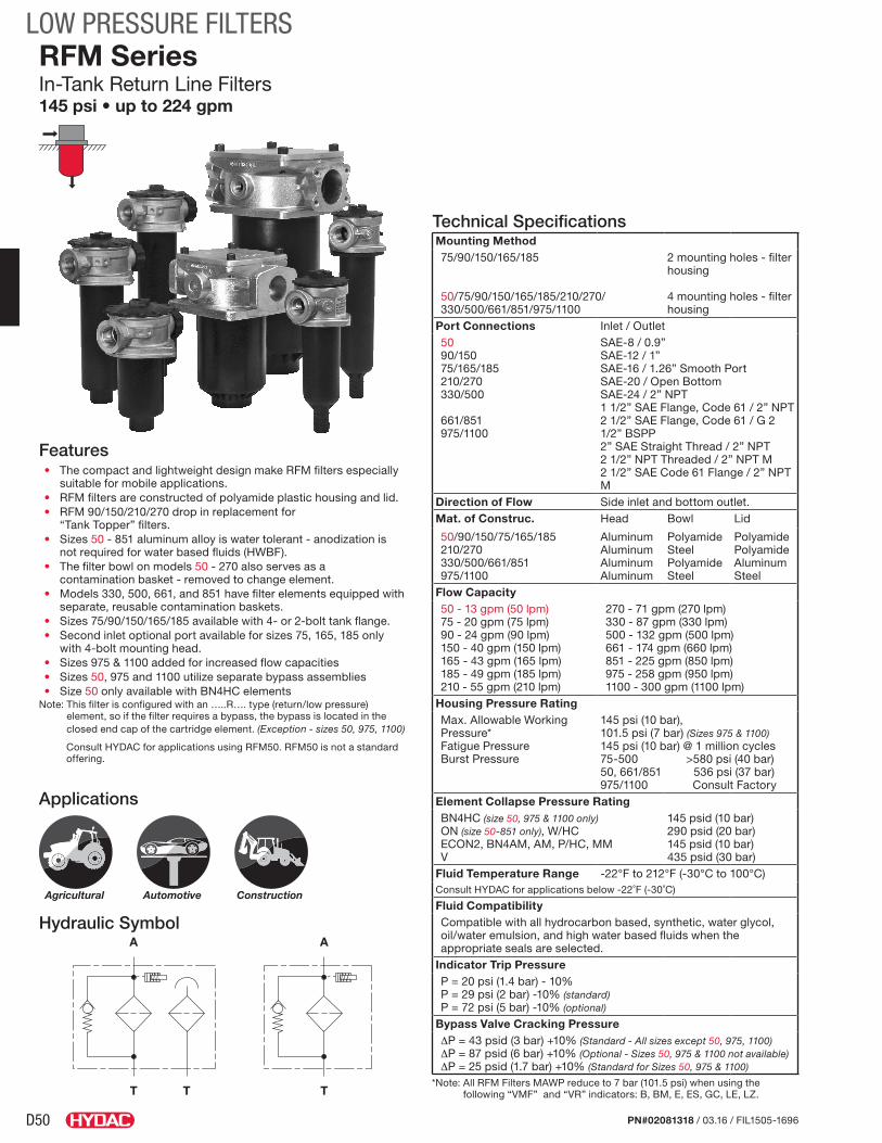
LOW PRESSURE FILTERS
PN#02081318 / 03.16 / FIL1505-1696
Hydraulic Symbol
Features• The compact and lightweight design make RFM filters especially
suitable for mobile applications.• RFM filters are constructed of polyamide plastic housing and lid.• RFM 90/150/210/270 drop in replacement for
“Tank Topper” filters.• Sizes 50 - 851 aluminum alloy is water tolerant - anodization is
not required for water based fluids (HWBF).• The filter bowl on models 50 - 270 also serves as a
contamination basket - removed to change element.• Models 330, 500, 661, and 851 have filter elements equipped with
separate, reusable contamination baskets.• Sizes 75/90/150/165/185 available with 4- or 2-bolt tank flange.• Second inlet optional port available for sizes 75, 165, 185 only
with 4-bolt mounting head.• Sizes 975 & 1100 added for increased flow capacities• Sizes 50, 975 and 1100 utilize separate bypass assemblies• Size 50 only available with BN4HC elements
Note: This filter is configured with an …..R…. type (return/low pressure) element, so if the filter requires a bypass, the bypass is located in the closed end cap of the cartridge element. (Exception - sizes 50, 975, 1100)
Consult HYDAC for applications using RFM50. RFM50 is not a standard offering.
RFM SeriesIn-Tank Return Line Filters145 psi • up to 224 gpm
A
T T
A
T
Technical SpecificationsMounting Method75/90/150/165/185
50/75/90/150/165/185/210/270/ 330/500/661/851/975/1100
2 mounting holes - filter housing 4 mounting holes - filter housing
Port Connections Inlet / Outlet5090/15075/165/185210/270330/500
661/851975/1100
SAE-8 / 0.9”SAE-12 / 1”SAE-16 / 1.26” Smooth PortSAE-20 / Open BottomSAE-24 / 2” NPT1 1/2” SAE Flange, Code 61 / 2” NPT2 1/2” SAE Flange, Code 61 / G 2 1/2” BSPP2” SAE Straight Thread / 2” NPT 2 1/2” NPT Threaded / 2” NPT M 2 1/2” SAE Code 61 Flange / 2” NPT M
Direction of Flow Side inlet and bottom outlet.Mat. of Construc. Head Bowl Lid
50/90/150/75/165/185210/270330/500/661/851975/1100
AluminumAluminumAluminumAluminum
PolyamideSteelPolyamideSteel
PolyamidePolyamideAluminumSteel
Flow Capacity50 - 13 gpm (50 lpm)75 - 20 gpm (75 lpm)90 - 24 gpm (90 lpm)150 - 40 gpm (150 lpm)165 - 43 gpm (165 lpm)185 - 49 gpm (185 lpm)210 - 55 gpm (210 lpm)
270 - 71 gpm (270 lpm)330 - 87 gpm (330 lpm)500 - 132 gpm (500 lpm)661 - 174 gpm (660 lpm)851 - 225 gpm (850 lpm)975 - 258 gpm (950 lpm)1100 - 300 gpm (1100 lpm)
Housing Pressure RatingMax. Allowable Working Pressure*Fatigue PressureBurst Pressure
145 psi (10 bar), 101.5 psi (7 bar) (Sizes 975 & 1100)145 psi (10 bar) @ 1 million cycles75-500 >580 psi (40 bar)50, 661/851 536 psi (37 bar)975/1100 Consult Factory
Element Collapse Pressure RatingBN4HC (size 50, 975 & 1100 only)ON (size 50-851 only), W/HCECON2, BN4AM, AM, P/HC, MM V
145 psid (10 bar)290 psid (20 bar)145 psid (10 bar) 435 psid (30 bar)
Fluid Temperature Range -22°F to 212°F (-30°C to 100°C)Consult HYDAC for applications below -22˚F (-30˚C)
Fluid Compatibility Compatible with all hydrocarbon based, synthetic, water glycol, oil/water emulsion, and high water based fluids when the appropriate seals are selected.
Indicator Trip PressureP = 20 psi (1.4 bar) - 10%P = 29 psi (2 bar) -10% (standard)P = 72 psi (5 bar) -10% (optional)
Bypass Valve Cracking Pressure∆P = 43 psid (3 bar) +10% (Standard - All sizes except 50, 975, 1100)∆P = 87 psid (6 bar) +10% (Optional - Sizes 50, 975 & 1100 not available)∆P = 25 psid (1.7 bar) +10% (Standard for Sizes 50, 975 & 1100)
*Note: All RFM Filters MAWP reduce to 7 bar (101.5 psi) when using the following “VMF” and “VR” indicators: B, BM, E, ES, GC, LE, LZ.
Applications
Agricultural Automotive Construction

D51
LOW PRESSURE FILTERS
PN#02081318 / 03.16 / FIL1505-1696
Model CodeRFM ON 330 B F F 3 D 1 . X / 12 - V - - L24.
Filter Type RFM = In-Tank Return Line FilterElement Media ON = Optimicron® BN/HC = Betamicron® (Sizes 50, 975, 1100 only) BN/AM = Betamicron®/Aquamicron® (Sizes 330 to 851 only) ECON2 = ECOmicron® (Not for sizes 50, 75, 210, 270) AM = Aquamicron® (Sizes 330 to 851 only) W/HC = Wire Mesh (Sizes 75 to 851) P/HC = Polyester (Sizes 330 to 851 only) MM = Mobilemicron® (Sizes 75 to 851)Size 50, 75, 90, 150, 165, 185, 210, 270, 330, 500, 661, 851, 975, 1100Working Pressure B = 145 psi (10 bar) V = 101.5 psi (7 bar) (975 & 1100 Standard* - Note previous page)Optional Second Inlet Connection (omit) = no second port M = 2 1/2” SAE Flange Code 61 D = 1” Threaded (SAE-16) (sz. 75, 165, 185) (sz. 661, 851, 975 & 1100 only) F = 1 1/2” Threaded (SAE-24) (sz. 330, 500 only) N = 2 1/2” NPT Threads (sz. 975, 1100 only) G = 2” Threaded Port (sz. 975, 1100 only) V = 2 x 1” (SAE-16) (sz. 210, 270 only) K = 1 1/2” SAE Flange Code 61 (sz. 330, 500 only)Inlet Connection/Port Size (1 Inlet) B = 1/2” Threaded (SAE-8) (sz. 50 only) N = 2 1/2” NPT Threads (sz. 975, 1100 only) C = 3/4” Threaded (SAE-12) (sz. 90, 150 only) Z = Customer Specific D = 1” Threaded (SAE-16) (sz. 75, 165 & 185 only E = 1 1/4” Threaded (SAE-20) (sz. 210, 270 only) F = 1 1/2” Threaded (SAE-24) (sz. 210, 270, 330, & 500 only) G = 2” Threaded Port (sz. 975 & 1100 only) K = 1 1/2” SAE Flange Code 61 (sz. 330, 500 only) M = 2 1/2” SAE Flange Code 61 (sz. 661, 851, 975 & 1100 only)Filtration Rating (microns) 1, 3, 5, 10, 15, 20 = ON 3, 5, 10, 20 = BN/HC 3, 10 = BN/AM 3, 5, 10, 20 = ECON2 40 = AM 25, 74, 149 = W/HC 10, 20 = P/HC 10, 15 = MMType of Static Clogging Indicator A, B, BM, C, D, E, F, FD (Others available upon request)Type Number 0 = no indicator, no ports 1-3 = clogging indicator positions (see chart)Modification Number (latest version always supplied)Inlet Port Configuration 0 = BSPP Straight Thread Ports 3 = NPT Ports (sizes 975, 1100 only) 12 = SAE Straight Thread O-Ring Boss Ports (sz. 50-500, 975, 1100) 16 = SAE Flange Code 61 (sz. 330-851, 975, 1100)Seals (omit) = Nitrile rubber (NBR) (standard) V = Fluorocarbon elastomer (FKM) EPR = Ethylene propylene rubber (EPR)Bypass Valve (omit) = 43 psid (3 bar) (standard) B1.7 = 25 psid (1.7 bar) (50, 975 & 1100 only setting available for bypass) B1 = 14.5 psid (1 bar) lube or coolant B6 = 87 psid (6 bar) (return line extended life)
not available with ECON2
KB = no bypass (flushing systems)Supplementary Details SO263 = Modification of ON and W/HC elements for Skydrol or HYJET phosphate ester fluids L24, L48, L110, L220 = Lamp for D-type clogging indicator (LXX, XX = voltage) SO150H = Anodized for high water based fluids, phosphate esters and skydrol fluids (sz. 975 & 1100 only) T = Filter Breather (sz. 75, 90, 150, 165, 185, 210, 270 only) - (includes oil separator on 2 bolt versions sizes 75, 165, 185 only) C = Outlet check valves (sizes 975, 1100 only) DTxx = Down tube (xx length in inches - up to 12 inches) 4L = 4 Bolt mounting flange (sizes 90-185) DSxx = Dip stick (xx length in inches) 2MO = Indicator with Deutsch Connector (FD indicator only) D = Diffuser (sizes 75, 165, 185 only) SFREE = Element specially designed to minimize electrostatic charge generation
Model Codes Containing RED are non-stock items — Minimum quantities may apply – Contact HYDAC for information and availability
Replacement Element Model Code0330 R 003 ON / V B6 .
Size 0050, 0075, 0090, 0150, 0165, 0185, 0210, 0270, 0330, 0500, 0660, 0850, 0975, 1100Filtration Rating (micron) 1, 3, 5, 10, 15, 20 = ON 3, 5, 10, 20 = BN4HC (sz. 50, 975, 1100 only) 3, 10 = BN4AM 3, 5, 10, 20 = ECON2 40 = AM 25, 74, 149 = W/HC 10, 20 = P/HC 10, 15 = MMElement Media ON, BN4HC, BN4AM, ECON2, AM, W/HC, P/HC, MMSeals (omit) = Nitrile rubber (NBR) (standard) V = Fluorocarbon elastomer (FKM) EPR = Ethylene propylene rubber (EPR)
Bypass Valve (omit) = 43 psid (3 bar) (standard) B1 = 14.5 psid (1 bar) B1.7 = 25 psid (1.7 bar) B6 = 87 psid (6 bar) KB = no bypass
Supplementary Details SO263 = (same as above) SFREE = (same as above)
Clogging Indicator Model CodeVR 2 D . X / V.
Indicator Prefix VR = Return Filters (sizes 330 to 851) VMF = Mobile Filters (sizes 75 to 270)
Trip Pressure 1.4 = 20 psid (1.4 bar) 2 = 29 psid (2 bar) 5 = 72 psid (5 bar) (optional)
Type of Indicator A = No indicator, plugged port BM = Pop-up indicator (manual reset) C = Electric switch - SPDT E = Visual pressure gauge F = Electric pressure switch FD = Electric pressure switch w/Deutsch ConnectorModification NumberSupplementary Details 2M0 = Deutsch Connector (male) Seals (omit) = Nitrile rubber (NBR) (standard) V = Fluorocarbon elastomer (FKM) EPR = Ethylene propylene rubber (EPR) (For additional details and options, see Section G - Clogging Indicators.)

D52
LOW PRESSURE FILTERS
PN#02081318 / 03.16 / FIL1505-1696
Clogging Indicator LocationsRFM 75/165/185
1.0
3.0 Plug
2.0
2.0Standard
Type No. Location of Clogging Indicator Indicator Model
2.X Clogging Indicator left front 45° to Inlet VMF...
3.X Clogging Indicator right front 45° to Inlet VMF...
RFM 90/150
RFM 90/150/-4L
RFM 75/165/185 (2 Bolt Mount)Type No. Location of Clogging Indicator Indicator Model
1.X Clogging Indicator left back 90° to Inlet VMF...
2.X Clogging Indicator left front 45° to Inlet VMF...
3.X Clogging Indicator right front 45° to Inlet VMF...
4.X Clogging Indicator left back 135° to Inlet VMF...
5.X Clogging Indicator left front 90° to Inlet VMF...
6.X Clogging Indicator right front 90° to Inlet VMF...
1.0 Standard
3.06.0
2.04.0
5.0
2.0
3.0
INLE
T
1.0
Primary INLET
Additional Port
RFM 75/165/185/-4L - Multi-Port RFM 75/165/185 - Multi-Port (4 Bolt Mount)Type No. Location of Clogging Indicator Indicator Model
1.X Clogging Indicator right of primary Inlet, 90° to Inlet VMF...
RFM 75/165/185/-4L RFM 75/165/185 - Single Port (4 Bolt Mount)Type No. Location of Clogging Indicator Indicator Model
2.X Clogging Indicator left front 90° to Inlet VMF...
3.X Clogging Indicator right front 90° to Inlet VMF...

D53
LOW PRESSURE FILTERS
PN#02081318 / 03.16 / FIL1505-1696
Clogging Indicator Locations (cont’d)Type No. Location of Clogging Indicator Indicator Model
1.X Clogging Indicator left back 45° to Inlet VMF...
2.X Clogging Indicator left front 45° to Inlet VMF...
3.X Clogging Indicator right front 45° to Inlet VMF...
4.X Clogging Indicator right back 45° to Inlet VMF...
2.0 Standard 3.0 Plug
4.0 Plug1.0 Plug
RFM 210/270
Type No. Location of Clogging Indicator Indicator Model
1.X Clogging Indicator left 90° to Inlet VR...
2.X Clogging Indicator right 90° to Inlet VR...
3.X Clogging Indicator on Top VR...
1.0Standard
2.0Special
3.0Special
RFM 330/500
1.0Standard
2.0Special
3.0Special
Type No. Location of Clogging Indicator Indicator Model
1.X Clogging Indicator left 90° to Inlet VR...
2.X Clogging Indicator right 90° to Inlet VR...
3.X Clogging Indicator on Top VR...
RFM 661/851

D54
LOW PRESSURE FILTERS
PN#02081318 / 03.16 / FIL1505-1696
Size 50Weight (lbs.) 1.5
Dimensions shown are [inches] millimeters for general information and overall envelope size only. Weights listed include element. For complete dimensions please contact HYDAC to request a certified print.
DimensionsRFM 50 - 4L
2.1655
Tank Cutout
2.3459.5
1.8346.5
2.0 position
G1/8" Static indicatorport
Inlet
1.0225.9
for element removalClearance required
238[9.37]
3/4"-16INLET
SAE-8
OUTLET
G 1/8" Static indicator port 1.0 position
225.3 8.87
72.4 2.85
I.D.0.76
19.2
0.9022.8 O.D.
11.72297.7
2.0 position
Mounting Pattern
0.246
4 places
3.0778
bolt circle
Hex25.41.00
773.03
3.3585
2.1655

D55
LOW PRESSURE FILTERS
PN#02081318 / 03.16 / FIL1505-1696
Size 75 165 185Weight (lbs.) 2.0 2.5 2.6
Dimensions shown are [inches] millimeters for general information and overall envelope size only. Weights listed include element. For complete dimensions please contact HYDAC to request a certified print.
DimensionsRFM 75/165/185 (2 Bolt)
0.4311
4.43
112.5
3.4688
Tank Openingw/ breather & oil separator
3.0778
Tank Openingwithout breather &
oil separator
3.1981
2.7269
2.9174
5.45
138.5
Mounting Pattern
G 1/8" Satic
for beather removalClearance required
Indicator ports
6 places
[1.57]40
(optional cast closed)
OUTLET
G1/8" Static indicatorportStandard 1.0postion
RFM 165: 230 [11.81]RFM185: 300 Clearance requiredfor element removal
SAE-16 port1 5/16-12INLET
[5.91]RFM 75: 150 [9.06]
Oil separator[On Breather Version]
1.8948
[Top of Bowl] 73.5
2.89
I.D.32
1.26
RFM185: 272 [10.71]RFM 165: 206
8.11
341.34
84.3
3.32
[4.80]RFM 75: 122
1.538 O.D.
Tank breather(Optional)
1.0627

D56
LOW PRESSURE FILTERS
PN#02081318 / 03.16 / FIL1505-1696
DimensionsRFM 75/165/185 - 4L Single Port (4 Bolt)
Size 75 165 185Weight (lbs.) 2.0 2.5 2.6
Dimensions shown are [inches] millimeters for general information and overall envelope size only. Weights listed include element. For complete dimensions please contact HYDAC to request a certified print.
0.359
4 places
4.96126
Bolt circle
Tank Cutout3.07
78
4.96126
7.04178.8
5.53
140.3
32 I.D.1.26
111 4.37
3.3083.7
2.7670
1104.33
0.359
Mounting Pattern
With Anti Splash)Note: Breather (BF10
2 placesIndicator PortsG 1/8" Static
SAE-16 port
INLET1 5/16-12
[5.91]RFM 75: 150 [9.06]RFM 165: 230 [11.8]RFM185: 300 Clearance requiredfor element removal
[7.99]
2.8973.5
RFM 75: 203 [11.29]
RFM 165: 287
[Top of Bowl]
813.19
RFM 185: 353 [10.71]
2.3660
INLET1-5/16"-12 UN-2BSAE-16 port
4.33110
2.7670
1.0627
Breather port
OUTLET
G 1/4"
G1/8" OptionStatic indicatorport
1.1930.3
O.D.381.5
702.76
[4.80]RFM 75: 122
[8.11]RFM 165: 206
[10.71]RFM 185: 272

D57
LOW PRESSURE FILTERS
PN#02081318 / 03.16 / FIL1505-1696
DimensionsRFM 75/165/185 - 4L Multi Port (4 Bolt)
Size 75 165 185Weight (lbs.) 2.0 2.5 2.6
Dimensions shown are [inches] millimeters for general information and overall envelope size only. Weights listed include element. For complete dimensions please contact HYDAC to request a certified print.
4.61117
4.17106
4.88124
74.52.93
3.1981
7.4188
0.359
4 places
4.96126
Bolt circle
3.0778
Tank opening
INLET1 5/16-12SAE-16 port
INLET1 5/16-12SAE-16 port(optional)
5.24 133
71 2.8
712.8
1.0627
[5.91]RFM 75: 150 [9.06]
INLET1 5/16-12
SAE-16 port
RFM185: 300 [11.81]RFM 165: 230
for element removal Clearance required
1.0G1/8" OptionStatic
indicatorport
1.2632
I.D.
401.57
813.19
RFM 185: 272 [10.71]
RFM 165: 206 [8.11]
RFM 75: 122 [4.80]
341.34
1.538
O.D.
port
Staticindicatorport
G1/8" Option
G 1/4" Breather
OUTLET
2.8973.5
Top of Bowl
"with breather-option"
Mounting Pattern
"without breather-option"

D58
LOW PRESSURE FILTERS
PN#02081318 / 03.16 / FIL1505-1696
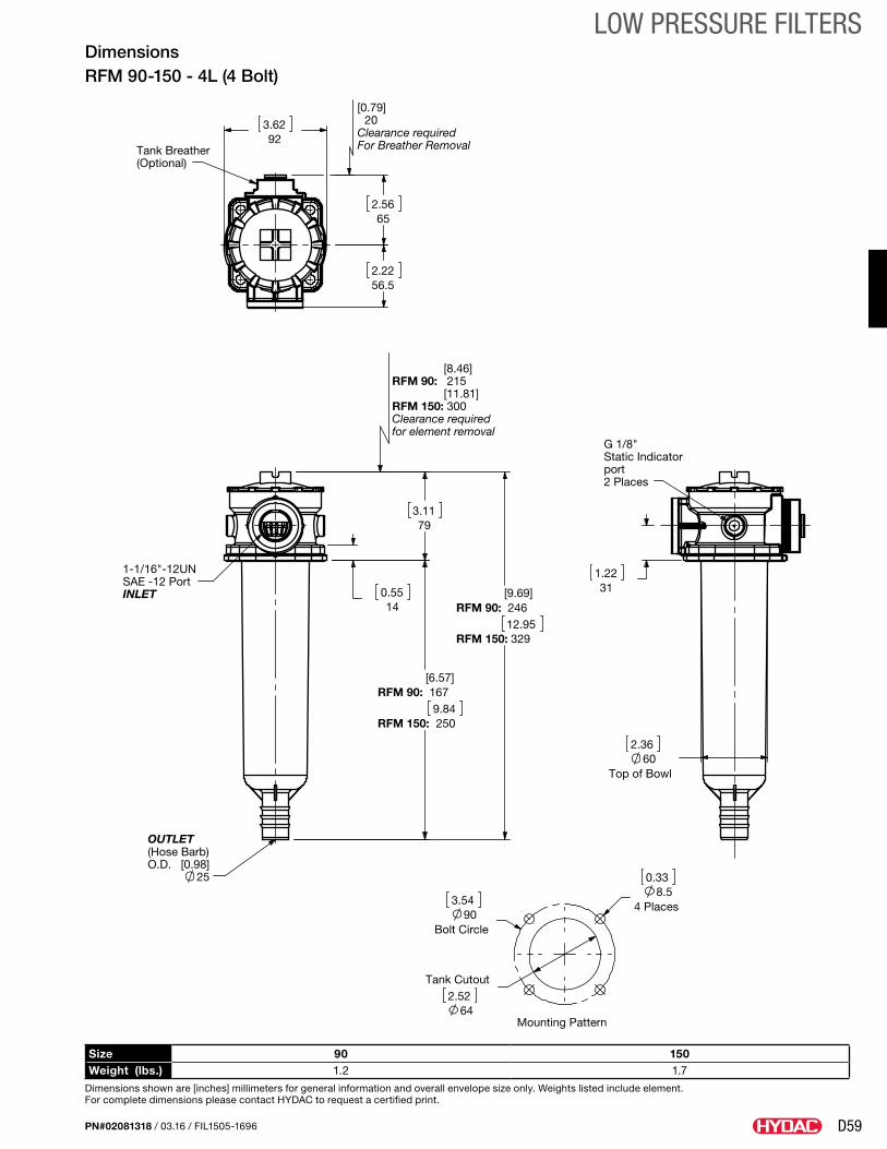
Size 90 150Weight (lbs.) 1.2 1.7
Dimensions shown are [inches] millimeters for general information and overall envelope size only. Weights listed include element. For complete dimensions please contact HYDAC to request a certified print.
DimensionsRFM 90-150 (2 Bolt)
0.338.5
2 places
3.5490
Tank Cutout2.52
64
4.37111
2.3660
Top of bowl
Tank breather(Optional)
2.56
56.52.22
With breather65
1.845.6
Without breather
25
Static indicator
1 1/16"-12UN
port
INLETSAE-12 Port
O.D. [0.98](Hose barb)OUTLET
G1/8"
[8.46]RFM 90: 215 [11.81]RFM 150: 300 Clearance requiredfor element removal
311.220.55
14
6.57167RFM 90:[9.84]
RFM 150: 250
3.1179
Clearance required20
for breather removal
Mounting Pattern
[0.79]
D59
LOW PRESSURE FILTERS
PN#02081318 / 03.16 / FIL1505-1696
Size 90 150Weight (lbs.) 1.2 1.7
Dimensions shown are [inches] millimeters for general information and overall envelope size only. Weights listed include element. For complete dimensions please contact HYDAC to request a certified print.
DimensionsRFM 90-150 - 4L (4 Bolt)
2.3660
Top of Bowl
Tank Cutout2.52
64
3.5490
Bolt Circle
0.338.5
4 Places
3.6292
G 1/8"Static Indicatorport2 Places
1.2231 SAE -12 Port
25
1-1/16"-12UN
INLET
OUTLET(Hose Barb)O.D. [0.98]
32912.95
RFM 150:
RFM 90: 246[9.69]
2509.84
RFM 150:
RFM 90: 167[6.57]
3.11 79
0.5514
Clearance required
[0.79]20
Mounting Pattern
for element removal
For Breather Removal
[8.46]RFM 90: 215 [11.81]RFM 150: 300Clearance required
(Optional)
Tank Breather
652.56
2.2256.5

D60
LOW PRESSURE FILTERS
PN#02081318 / 03.16 / FIL1505-1696
Size 210 270Weight (lbs.) 7 9.5
Dimensions shown are [inches] millimeters for general information and overall envelope size only. Weights listed include element. For complete dimensions please contact HYDAC to request a certified print.
DimensionsRFM 210/270
6.89175
1.5439
6.1155
4.13105
Tank opening
Open bottom OUTLET
34[1.34]
INLET1 7/8"-12UNSAE-24 Port
3.7896
0.4311
1.3835
348RFM 210: [18.89]
RFM270: 480
13.68
RFM 210: 9.9252
[15.12]RFM270: 384
G 1/8"Static indicator
ports4 places
172.56.79
3.94100
95 3.74
172.56.79
1.4236
RFM270: 410
for element removal
[16.14]
Clearance required
RFM 210: [11.02]280
Mounting Pattern
0.4311
4 places
6.69170
bolt circle

D61
LOW PRESSURE FILTERS
PN#02081318 / 03.16 / FIL1505-1696
Size 330 500Weight (lbs.) 8.6 10
Dimensions shown are [inches] millimeters for general information and overall envelope size only. Weights listed include element. For complete dimensions please contact HYDAC to request a certified print.
DimensionsRFM 330/500
Tank Opening5127
5.83148
6.1155
4.81122.2
Top of Bowl
Mounting Pattern
4 places
0.4311
6.99177.5
Bolt circle
8.27210
1857.28
G 1/2"Static indicatorport
1 1/2" SAE code 61flange
2.75 69.9
1.4135.7 1/2"-13UNC-2B Thru
RFM 330: [7.87]
2" NPTOUTLET
Clearance required
200
for element removal
[11.22]RFM 500: 285
1-7/8"-12UNSAE-24 PortINLET or 1 1/2" SAE Flange-Code 61 Port
2 50.7
4.06 103.1
6.26159RFM 330:
[9.45]RFM500: 240
RFM 330: 10.32262.1
[13.51]RFM500: 343.1

D62
LOW PRESSURE FILTERS
PN#02081318 / 03.16 / FIL1505-1696
Size 661 851Weight (lbs.) 19.9 23.2
Dimensions shown are [inches] millimeters for general information and overall envelope size only. Weights listed include element. For complete dimensions please contact HYDAC to request a certified print.
DimensionsRFM 661/851
4.78121.5
6.69170
Tank Opening
RFM 851: 420 [16.54]
Clearance required
340
for element removal
RFM 661: [13.39]
INLET PORT2 1/2" SAE FlangeCode 61
OUTLETG 2 1/2"
1/2"-13UNC-2A Thru
RFM 661: 300 [15.20]
RFM 851: 386
3.588.9
50.8
55
2
2.17
11.81
RFM 661: 16.59421.5
[19.98]RFM 851: 507.5
Static indicatorportG 1/2"
6.5165.2
[Top of Bowl]
9.92252
9.09231
Mounting Pattern
0.5313.5
4 places
8.66220
bolt circle

D63
LOW PRESSURE FILTERS
PN#02081318 / 03.16 / FIL1505-1696
Size 975 1100Weight (lbs.) 37 52
Dimensions shown are [inches] millimeters for general information and overall envelope size only. Weights listed include element. For complete dimensions please contact HYDAC to request a certified print.
DimensionsRFM 975/1100
25.87657.1RFM 975:
[43.63]RFM 110: 1108.1
6.61168
5.98152
9.35
237.6
for element removalClearance required
RFM 1100: [36.06] 916
RFM 975: [18.31] 465
3" NPT maleOUTLET
[35.5]RFM 1100: 902
87
[17.76]RFM 975: 451
3.43
1.538.1
INLET
Mounting Pattern
code 61
Standard INLET2" SAE or
2 1/2" NPTor
2 1/2" SAE
Dirt AlarmorElectrical switch1/8" NPT Port
INLETStandard
INLETOptionalStandard
IndicatorPort 1/8" NPT
222.28.75
235
9.25
Threaded [9.00]228.6
Bolt circle 213
8.39
Equally Spaced
0.564 X 14
Tank Opening6.89
175
2 1/2" SAE code 61 flange(optional)
PortINLET
1/2"-13UNC
50.82
3.5
88.9

D64
LOW PRESSURE FILTERS
PN#02081318 / 03.16 / FIL1505-1696
Sizing InformationTotal pressure loss through the filter is as follows:
Assembly ∆P = Housing ∆P + Element ∆P
Housing Curve:
Pressure loss through housing is as follows:
Housing ∆P = Housing Curve ∆P x Actual Specific Gravity
0.86
Adjustments must be made for viscosity & specific gravity of the fluid to be used! (see “Sizing HYDAC Filter Assemblies” in Section B - Overview)
0
0
0.05
0.10
0.15
0.20
0.25
0.30
0
1
2
3
4
5
Q in gpm
Q in l/minRFM 661/851Housing
0 40 80 120 160 250
300 6000 200 300100 400
0
0.05
0.10
0.15
0.20
0.25
0.30
0
1
2
3
4
5
Q in gpm
RFM 330/500 Housing
0 25 50 75 100 125
Q in l/min
4
2
8
6
10
0100
400
0
0.25
0.50
Q in l/min
Q in gpm
RFM 975 / 1100 Housing
200
w/Check Valve
w/o Check Valve
150 250 300
600 1000800
RFM 75/165/185 & RFM 75/165/185/-4L Housing
00 0
0.05
0.10
0.15
0.20
0.25
0.30
1
2
3
4
5
10 20 30 40 50Q in gpm
Q in l/min0 80 12040 160
00.1
0.3
0.50.6
0.4
0.2
0 60Q in l/min
302010 40 50
Q in gpm
RFM 50/-4L Housing
8
6
4
2
10
01614128642 100 18
0
0.1
0.2
0.3
0.4
0Q in l/min
40 80 120
Q in gpm
RFM 90/150 & RFM 90/150/-4L Housing
654321
7
03020100 40
0
0.2
0.1
0.3
0.4
Q in l/min
Q in gpm
RFM 210 / 270 Housing
3
2
1
5
4
6
040200 8060 100
1000 200 300
D65
LOW PRESSURE FILTERS
PN#02081318 / 03.16 / FIL1505-1696
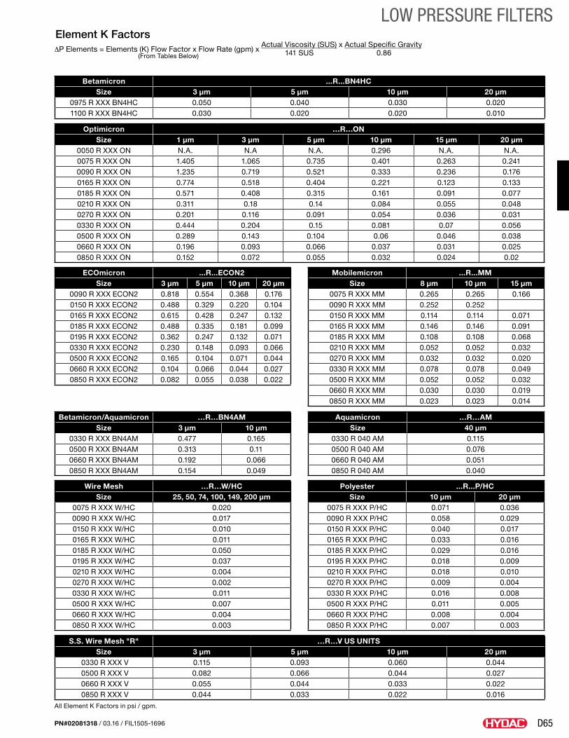
All Element K Factors in psi / gpm.
Element K Factors∆P Elements = Elements (K) Flow Factor x Flow Rate (gpm) x
Actual Viscosity (SUS) x Actual Specific Gravity (From Tables Below) 141 SUS 0.86
Wire Mesh …R…W/HC Size 25, 50, 74, 100, 149, 200 µm
0075 R XXX W/HC 0.0200090 R XXX W/HC 0.0170150 R XXX W/HC 0.0100165 R XXX W/HC 0.0110185 R XXX W/HC 0.0500195 R XXX W/HC 0.0370210 R XXX W/HC 0.0040270 R XXX W/HC 0.0020330 R XXX W/HC 0.0110500 R XXX W/HC 0.0070660 R XXX W/HC 0.0040850 R XXX W/HC 0.003
Polyester ...R...P/HCSize 10 μm 20 μm
0075 R XXX P/HC 0.071 0.0360090 R XXX P/HC 0.058 0.0290150 R XXX P/HC 0.040 0.0170165 R XXX P/HC 0.033 0.0160185 R XXX P/HC 0.029 0.0160195 R XXX P/HC 0.018 0.0090210 R XXX P/HC 0.018 0.0100270 R XXX P/HC 0.009 0.0040330 R XXX P/HC 0.016 0.0080500 R XXX P/HC 0.011 0.0050660 R XXX P/HC 0.008 0.0040850 R XXX P/HC 0.007 0.003
Betamicron/Aquamicron …R…BN4AMSize 3 µm 10 µm
0330 R XXX BN4AM 0.477 0.1650500 R XXX BN4AM 0.313 0.110660 R XXX BN4AM 0.192 0.0660850 R XXX BN4AM 0.154 0.049
Aquamicron …R…AMSize 40 µm
0330 R 040 AM 0.1150500 R 040 AM 0.0760660 R 040 AM 0.0510850 R 040 AM 0.040
Optimicron …R…ON Size 1 µm 3 µm 5 µm 10 µm 15 µm 20 µm
0050 R XXX ON N.A. N.A N.A. 0.296 N.A. N.A.0075 R XXX ON 1.405 1.065 0.735 0.401 0.263 0.2410090 R XXX ON 1.235 0.719 0.521 0.333 0.236 0.1760165 R XXX ON 0.774 0.518 0.404 0.221 0.123 0.1330185 R XXX ON 0.571 0.408 0.315 0.161 0.091 0.0770210 R XXX ON 0.311 0.18 0.14 0.084 0.055 0.0480270 R XXX ON 0.201 0.116 0.091 0.054 0.036 0.0310330 R XXX ON 0.444 0.204 0.15 0.081 0.07 0.0560500 R XXX ON 0.289 0.143 0.104 0.06 0.046 0.0380660 R XXX ON 0.196 0.093 0.066 0.037 0.031 0.0250850 R XXX ON 0.152 0.072 0.055 0.032 0.024 0.02
ECOmicron ...R...ECON2Size 3 μm 5 μm 10 μm 20 μm
0090 R XXX ECON2 0.818 0.554 0.368 0.1760150 R XXX ECON2 0.488 0.329 0.220 0.1040165 R XXX ECON2 0.615 0.428 0.247 0.1320185 R XXX ECON2 0.488 0.335 0.181 0.0990195 R XXX ECON2 0.362 0.247 0.132 0.0710330 R XXX ECON2 0.230 0.148 0.093 0.0660500 R XXX ECON2 0.165 0.104 0.071 0.0440660 R XXX ECON2 0.104 0.066 0.044 0.0270850 R XXX ECON2 0.082 0.055 0.038 0.022
Mobilemicron ...R...MMSize 8 μm 10 μm 15 μm
0075 R XXX MM 0.265 0.265 0.1660090 R XXX MM 0.252 0.2520150 R XXX MM 0.114 0.114 0.0710165 R XXX MM 0.146 0.146 0.0910185 R XXX MM 0.108 0.108 0.0680210 R XXX MM 0.052 0.052 0.0320270 R XXX MM 0.032 0.032 0.0200330 R XXX MM 0.078 0.078 0.0490500 R XXX MM 0.052 0.052 0.0320660 R XXX MM 0.030 0.030 0.0190850 R XXX MM 0.023 0.023 0.014
Betamicron ...R...BN4HCSize 3 μm 5 μm 10 μm 20 μm
0975 R XXX BN4HC 0.050 0.040 0.030 0.0201100 R XXX BN4HC 0.030 0.020 0.020 0.010
S.S. Wire Mesh "R" …R…V US UNITSSize 3 μm 5 μm 10 μm 20 μm
0330 R XXX V 0.115 0.093 0.060 0.044 0500 R XXX V 0.082 0.066 0.044 0.027 0660 R XXX V 0.055 0.044 0.033 0.022 0850 R XXX V 0.044 0.033 0.022 0.016