Embed Size (px)
Citation preview
Quality, Comfort & Peace of Mind
Series 6000 Vinyl Fixed, Horizontal & Vertical Sliding Window
Quality, Comfort & Peace of Mind

2
Email any project-specific enquiries to [email protected] Starline Windows reserves the right to change or discontinue this product without notice.
Foreword This Design Guide provides specifications on the Series 6000 Vinyl Fixed Horizontal & Vertical Sliding Window.
This document is intended to provide information on our standard products. Non-standard designs and applications can be reviewed to determine the feasibility on a project-specific basis.
Please email any project specific enquiries to [email protected] or [email protected].
This document subject to change without notice.
Starline Windows reserves the right to change or discontinue this product without notice.
www.starlinewindows.com
Document Number TS-00013
© 2021-06-25 Starline Windows
Series 6000 Vinyl Sliding Window Design Guidelines
Email any project-specific enquiries to [email protected] Starline Windows reserves the right to change or discontinue this product without notice.
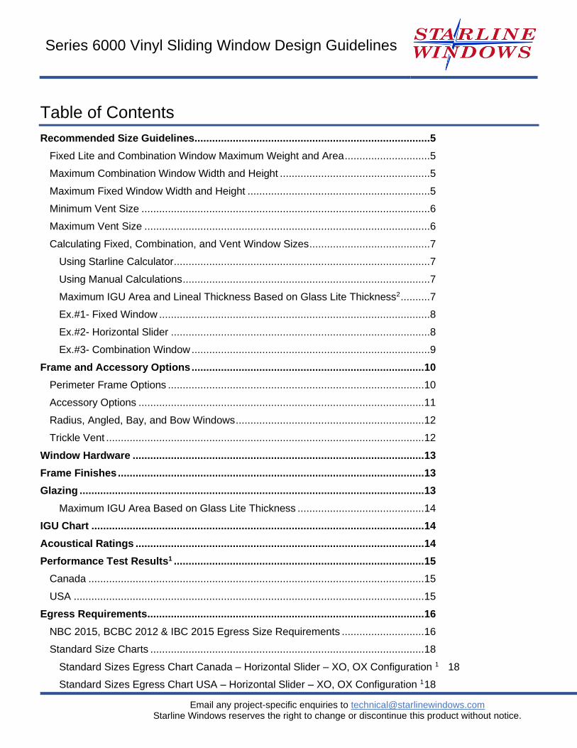
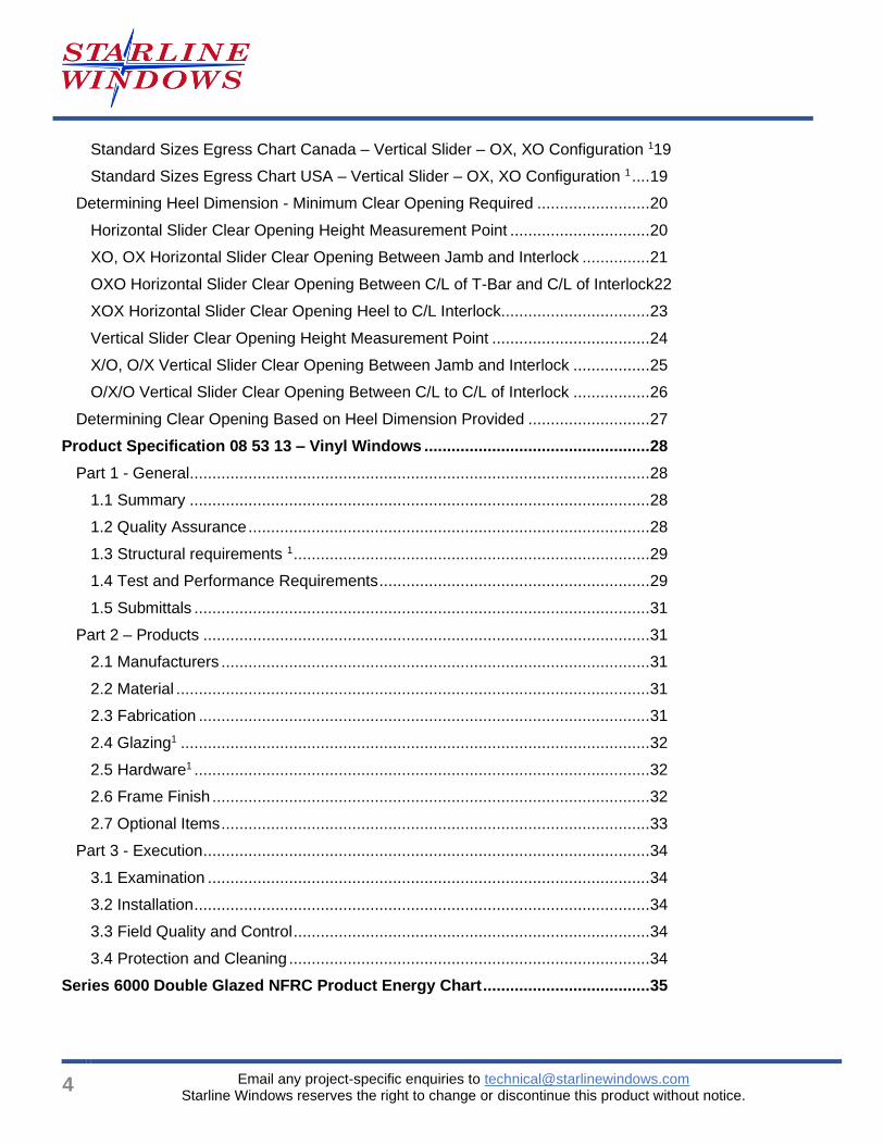
Table of Contents
Recommended Size Guidelines ................................................................................5
Fixed Lite and Combination Window Maximum Weight and Area .............................5
Maximum Combination Window Width and Height ...................................................5
Maximum Fixed Window Width and Height ..............................................................5
Minimum Vent Size ..................................................................................................6
Maximum Vent Size .................................................................................................6
Calculating Fixed, Combination, and Vent Window Sizes .........................................7
Using Starline Calculator .......................................................................................7
Using Manual Calculations ....................................................................................7
Maximum IGU Area and Lineal Thickness Based on Glass Lite Thickness2 ..........7
Ex.#1- Fixed Window ............................................................................................8
Ex.#2- Horizontal Slider ........................................................................................8
Ex.#3- Combination Window .................................................................................9
Frame and Accessory Options ............................................................................... 10
Perimeter Frame Options ....................................................................................... 10
Accessory Options ................................................................................................. 11
Radius, Angled, Bay, and Bow Windows ................................................................ 12
Trickle Vent ............................................................................................................ 12
Window Hardware ................................................................................................... 13
Frame Finishes ........................................................................................................ 13
Glazing ..................................................................................................................... 13
Maximum IGU Area Based on Glass Lite Thickness ........................................... 14
IGU Chart ................................................................................................................. 14
Acoustical Ratings .................................................................................................. 14
Performance Test Results1 ..................................................................................... 15
Canada .................................................................................................................. 15
USA ....................................................................................................................... 15
Egress Requirements .............................................................................................. 16
NBC 2015, BCBC 2012 & IBC 2015 Egress Size Requirements ............................ 16
Standard Size Charts ............................................................................................. 18
Standard Sizes Egress Chart Canada – Horizontal Slider – XO, OX Configuration 1 18
Standard Sizes Egress Chart USA – Horizontal Slider – XO, OX Configuration 1 18
4
Email any project-specific enquiries to [email protected] Starline Windows reserves the right to change or discontinue this product without notice.
Standard Sizes Egress Chart Canada – Vertical Slider – OX, XO Configuration 119
Standard Sizes Egress Chart USA – Vertical Slider – OX, XO Configuration 1 .... 19
Determining Heel Dimension - Minimum Clear Opening Required ......................... 20
Horizontal Slider Clear Opening Height Measurement Point ............................... 20
XO, OX Horizontal Slider Clear Opening Between Jamb and Interlock ............... 21
OXO Horizontal Slider Clear Opening Between C/L of T-Bar and C/L of Interlock22
XOX Horizontal Slider Clear Opening Heel to C/L Interlock................................. 23
Vertical Slider Clear Opening Height Measurement Point ................................... 24
X/O, O/X Vertical Slider Clear Opening Between Jamb and Interlock ................. 25
O/X/O Vertical Slider Clear Opening Between C/L to C/L of Interlock ................. 26
Determining Clear Opening Based on Heel Dimension Provided ........................... 27
Product Specification 08 53 13 – Vinyl Windows .................................................. 28
Part 1 - General ...................................................................................................... 28
1.1 Summary ...................................................................................................... 28
1.2 Quality Assurance ......................................................................................... 28
1.3 Structural requirements 1 ............................................................................... 29
1.4 Test and Performance Requirements ............................................................ 29
1.5 Submittals ..................................................................................................... 31
Part 2 – Products ................................................................................................... 31
2.1 Manufacturers ............................................................................................... 31
2.2 Material ......................................................................................................... 31
2.3 Fabrication .................................................................................................... 31
2.4 Glazing1 ........................................................................................................ 32
2.5 Hardware1 ..................................................................................................... 32
2.6 Frame Finish ................................................................................................. 32
2.7 Optional Items ............................................................................................... 33
Part 3 - Execution ................................................................................................... 34
3.1 Examination .................................................................................................. 34
3.2 Installation ..................................................................................................... 34
3.3 Field Quality and Control ............................................................................... 34
3.4 Protection and Cleaning ................................................................................ 34
Series 6000 Double Glazed NFRC Product Energy Chart ..................................... 35
Series 6000 Vinyl Sliding Window Design Guidelines
Email any project-specific enquiries to [email protected] Starline Windows reserves the right to change or discontinue this product without notice.
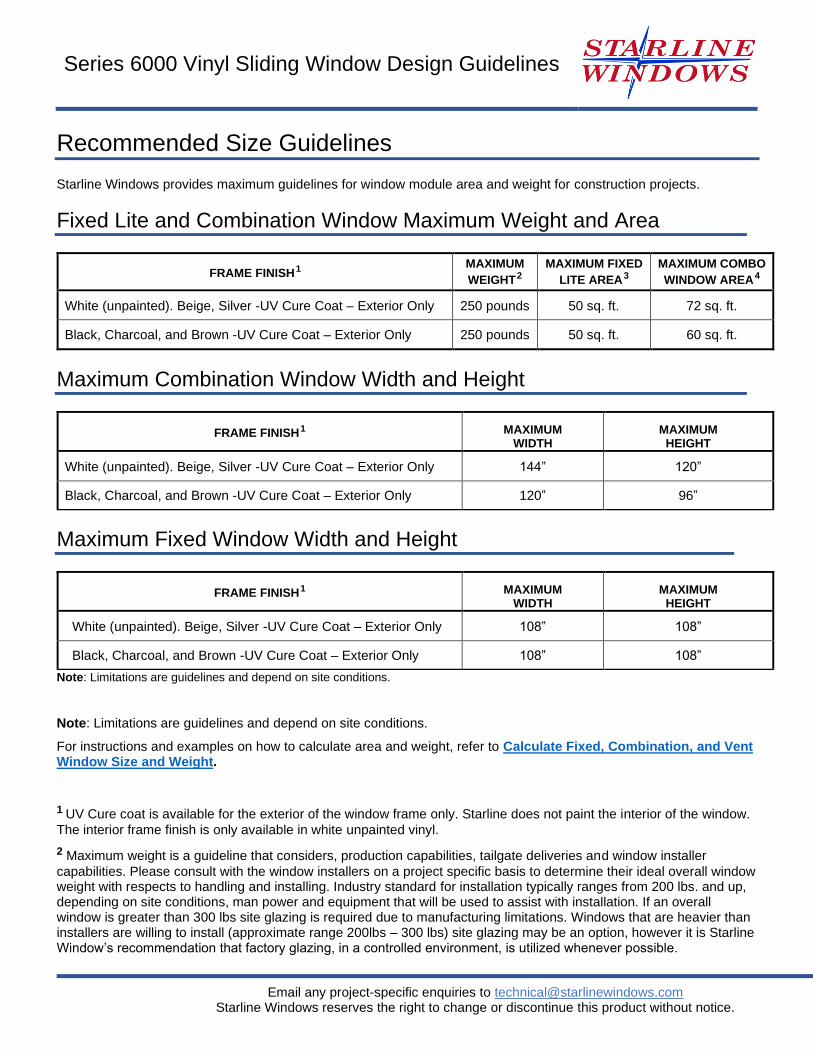
Recommended Size Guidelines
Starline Windows provides maximum guidelines for window module area and weight for construction projects.
Fixed Lite and Combination Window Maximum Weight and Area
FRAME FINISH
1 MAXIMUM
WEIGHT
2
MAXIMUM FIXED
LITE AREA
3
MAXIMUM COMBO
WINDOW AREA
4
White (unpainted). Beige, Silver -UV Cure Coat – Exterior Only 250 pounds 50 sq. ft. 72 sq. ft.
Black, Charcoal, and Brown -UV Cure Coat – Exterior Only 250 pounds 50 sq. ft. 60 sq. ft.
Maximum Combination Window Width and Height
FRAME FINISH
1 MAXIMUM WIDTH
MAXIMUM HEIGHT
White (unpainted). Beige, Silver -UV Cure Coat – Exterior Only 144” 120”
Black, Charcoal, and Brown -UV Cure Coat – Exterior Only 120” 96”
Maximum Fixed Window Width and Height
FRAME FINISH
1 MAXIMUM WIDTH
MAXIMUM HEIGHT
White (unpainted). Beige, Silver -UV Cure Coat – Exterior Only 108” 108”
Black, Charcoal, and Brown -UV Cure Coat – Exterior Only 108” 108”
Note: Limitations are guidelines and depend on site conditions.
Note: Limitations are guidelines and depend on site conditions.
For instructions and examples on how to calculate area and weight, refer to Calculate Fixed, Combination, and Vent Window Size and Weight.
1 UV Cure coat is available for the exterior of the window frame only. Starline does not paint the interior of the window.
The interior frame finish is only available in white unpainted vinyl.
2 Maximum weight is a guideline that considers, production capabilities, tailgate deliveries and window installer
capabilities. Please consult with the window installers on a project specific basis to determine their ideal overall window weight with respects to handling and installing. Industry standard for installation typically ranges from 200 lbs. and up, depending on site conditions, man power and equipment that will be used to assist with installation. If an overall window is greater than 300 lbs site glazing is required due to manufacturing limitations. Windows that are heavier than installers are willing to install (approximate range 200lbs – 300 lbs) site glazing may be an option, however it is Starline Window’s recommendation that factory glazing, in a controlled environment, is utilized whenever possible.
6
Email any project-specific enquiries to [email protected] Starline Windows reserves the right to change or discontinue this product without notice.
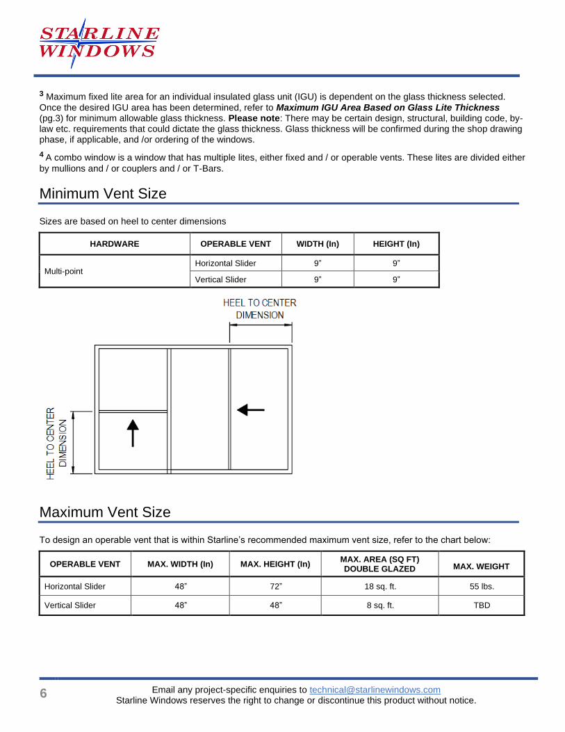
3 Maximum fixed lite area for an individual insulated glass unit (IGU) is dependent on the glass thickness selected.
Once the desired IGU area has been determined, refer to Maximum IGU Area Based on Glass Lite Thickness (pg.3) for minimum allowable glass thickness. Please note: There may be certain design, structural, building code, by-law etc. requirements that could dictate the glass thickness. Glass thickness will be confirmed during the shop drawing phase, if applicable, and /or ordering of the windows.
4 A combo window is a window that has multiple lites, either fixed and / or operable vents. These lites are divided either
by mullions and / or couplers and / or T-Bars.
Minimum Vent Size
Sizes are based on heel to center dimensions
HARDWARE OPERABLE VENT WIDTH (In) HEIGHT (In)
Multi-point Horizontal Slider 9” 9”
Vertical Slider 9” 9”
Maximum Vent Size
To design an operable vent that is within Starline’s recommended maximum vent size, refer to the chart below:
OPERABLE VENT MAX. WIDTH (In) MAX. HEIGHT (In) MAX. AREA (SQ FT) DOUBLE GLAZED
MAX. WEIGHT
Horizontal Slider 48” 72” 18 sq. ft. 55 lbs.
Vertical Slider 48” 48” 8 sq. ft. TBD
Series 6000 Vinyl Sliding Window Design Guidelines
Email any project-specific enquiries to [email protected] Starline Windows reserves the right to change or discontinue this product without notice.
Calculating Fixed, Combination, and Vent Window Sizes
Using Starline Calculator
Starline has a Maximum Fixed, Combination and Vent Window Size Calculator available for use. Enter the required parameters and the calculator will advise if the window is within Starline’s recommended design guidelines (PASS) or if it exceeds a certain parameter (FAIL). To retain a copy of this calculator contact [email protected]
Note: This calculator is a tool to assist with the design of basic window configurations. Combination windows can be complicated, and some configurations may need to be reviewed and approved by Starline’s Designers and /or Structural Engineer for feasibility and structural compliance.
For any type of window; fixed, combination and /or vents, there may be certain design and / or structural requirements, building code requirements, by-law requirements, etc. which require consideration and could dictate the size of the window, glass thickness, etc. Final window sizes and configurations will be confirmed during the shop drawing phase, if applicable, and /or ordering of the windows.
Using Manual Calculations
Once the fixed and /or combination window and /or vent style has been selected, along with the frame dimensions (width and height) and the glass thickness, a calculation can be performed to determine the area and weight of the window. The following examples are intended to provide sample calculations for the following window configurations:
Example #1: is intended to provide a sample calculation for a fixed window 1.
Example #2: is intended to provide sample calculations for a sliding vent. Please note: Whether a horizontal or vertical slider is used the calculation methodology is the same.
Example #3: is intended to provide a sample calculation for a combination window.
Glass thickness can play a significant factor in determining how large the window can be. The thicker the glass, the heavier the IGU. When thicker glass is selected commonly the maximum weight allowed is reached prior to the maximum area allowed.
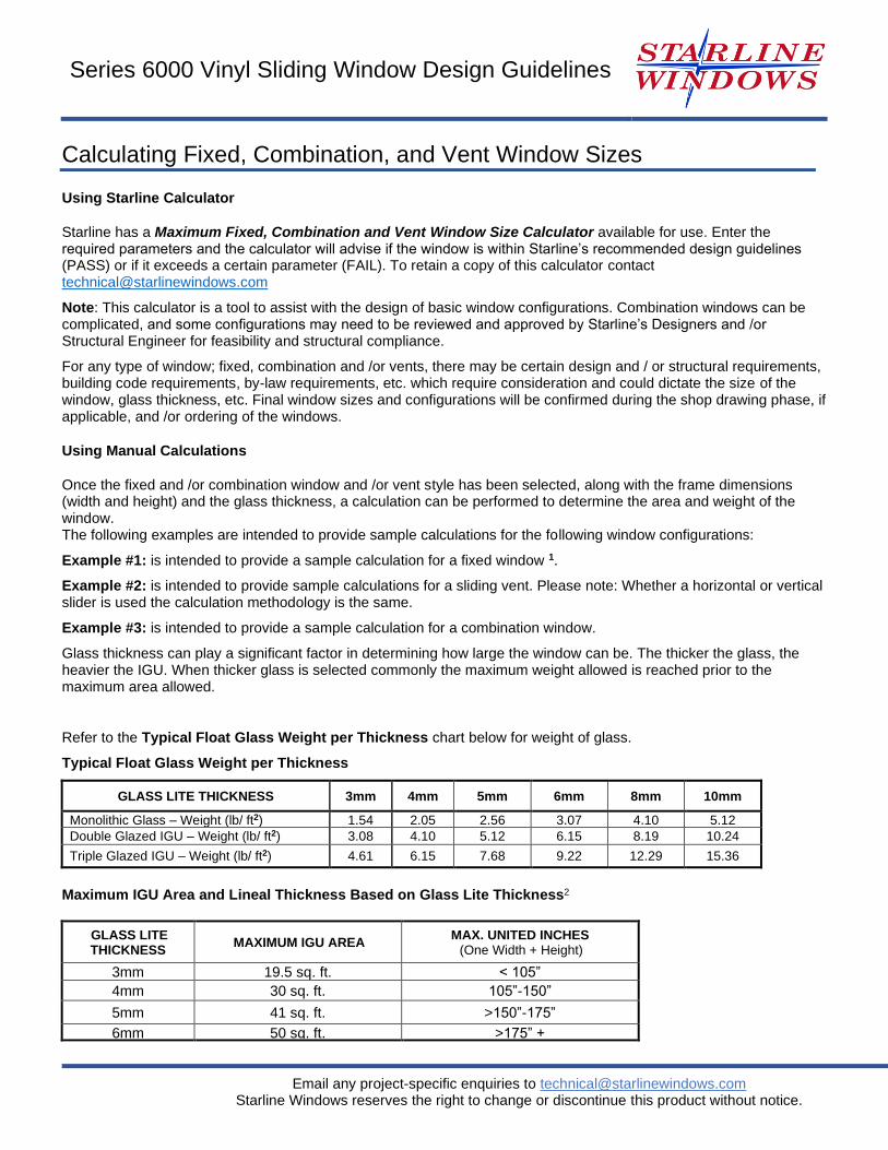
Refer to the Typical Float Glass Weight per Thickness chart below for weight of glass.
Typical Float Glass Weight per Thickness
GLASS LITE THICKNESS 3mm 4mm 5mm 6mm 8mm 10mm
Monolithic Glass – Weight (lb/ ft2) 1.54 2.05 2.56 3.07 4.10 5.12
Double Glazed IGU – Weight (lb/ ft2) 3.08 4.10 5.12 6.15 8.19 10.24
Triple Glazed IGU – Weight (lb/ ft2) 4.61 6.15 7.68 9.22 12.29 15.36
Maximum IGU Area and Lineal Thickness Based on Glass Lite Thickness2
GLASS LITE THICKNESS
MAXIMUM IGU AREA MAX. UNITED INCHES
(One Width + Height)
3mm 19.5 sq. ft. < 105”
4mm 30 sq. ft. 105”-150”
5mm 41 sq. ft. >150”-175”
6mm 50 sq. ft. >175” +
8
Email any project-specific enquiries to [email protected] Starline Windows reserves the right to change or discontinue this product without notice.
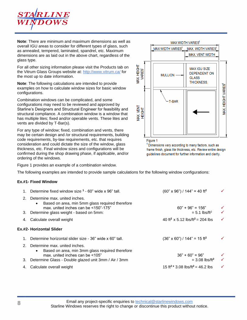
Note: There are minimum and maximum dimensions as well as overall IGU areas to consider for different types of glass, such as annealed, tempered, laminated, spandrel, etc. Maximum dimensions are as laid out in the above chart, regardless of the glass type.
For all other sizing information please visit the Products tab on the Vitrum Glass Groups website at: http://www.vitrum.ca/ for the most up to date information.
Note: The following calculations are intended to provide examples on how to calculate window sizes for basic window configurations.
Combination windows can be complicated, and some configurations may need to be reviewed and approved by Starline’s Designers and Structural Engineer for feasibility and structural compliance. A combination window is a window that has multiple lites; fixed and/or operable vents. These lites and vents are divided by T-Bar(s).
For any type of window; fixed, combination and vents, there may be certain design and /or structural requirements, building code requirements, by-law requirements, etc. that requires consideration and could dictate the size of the window, glass thickness, etc. Final window sizes and configurations will be confirmed during the shop drawing phase, if applicable, and/or ordering of the windows.
Figure 1 provides an example of a combination window.
The following examples are intended to provide sample calculations for the following window configurations:
Ex.#1- Fixed Window
1. Determine fixed window size 1 - 60” wide x 96” tall. (60” x 96”) / 144” = 40 ft2
2. Determine max. united inches.
• Based on area, min 5mm glass required therefore max. united inches can be <150”-175” 60” + 96” = 156”
3. Determine glass weight - based on 5mm: = 5.1 lbs/ft2
4. Calculate overall weight 40 ft2 x 5.12 lbs/ft2 = 204 lbs
Ex.#2- Horizontal Slider
1. Determine horizontal slider size - 36” wide x 60” tall. (36” x 60”) / 144” = 15 ft2
2. Determine max. united inches.
• Based on area, min 3mm glass required therefore max. united inches can be <105” 36” + 60” = 96”
3. Determine Glass - Double glazed unit 3mm / Air / 3mm = 3.08 lbs/ft2
4. Calculate overall weight 15 ft2 x 3.08 lbs/ft2 = 46.2 lbs
Series 6000 Vinyl Sliding Window Design Guidelines
Email any project-specific enquiries to [email protected] Starline Windows reserves the right to change or discontinue this product without notice.
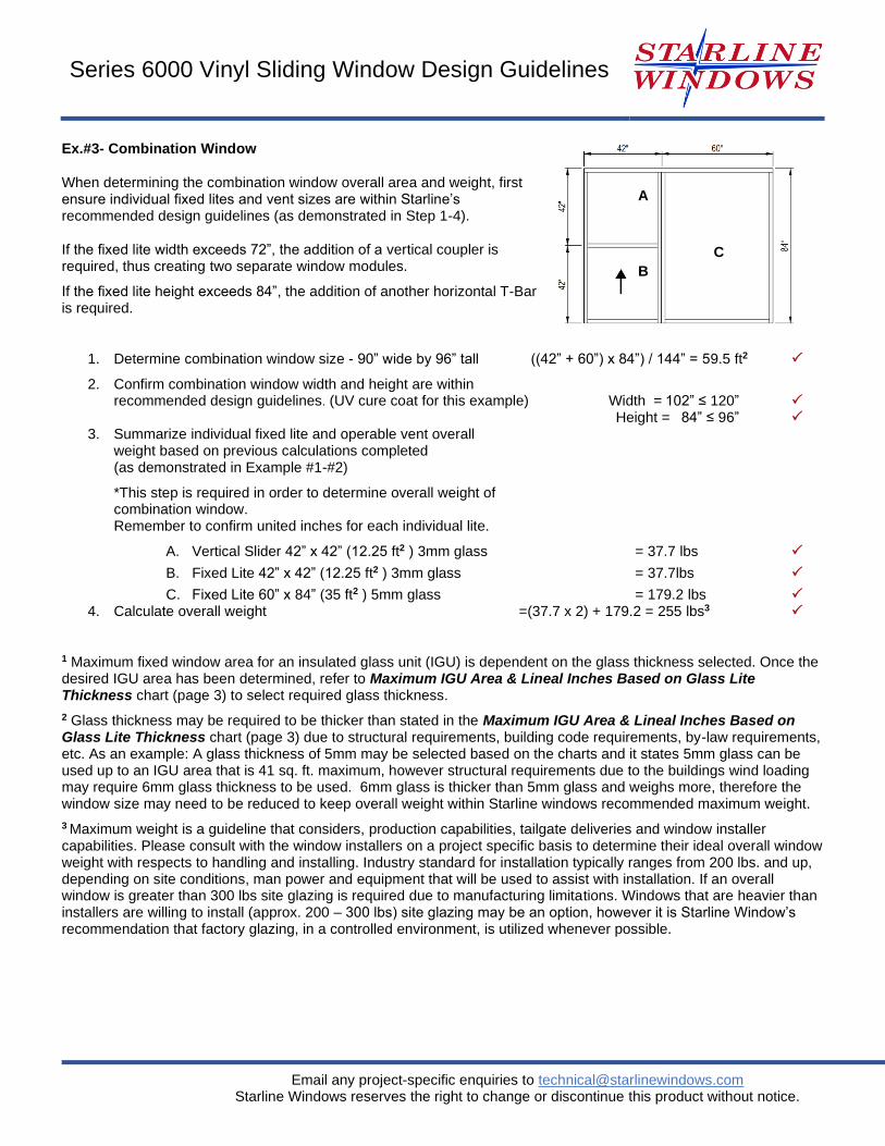
Ex.#3- Combination Window
When determining the combination window overall area and weight, first ensure individual fixed lites and vent sizes are within Starline’s recommended design guidelines (as demonstrated in Step 1-4).
If the fixed lite width exceeds 72”, the addition of a vertical coupler is required, thus creating two separate window modules.
If the fixed lite height exceeds 84”, the addition of another horizontal T-Bar is required.
1. Determine combination window size - 90” wide by 96” tall ((42” + 60”) x 84”) / 144” = 59.5 ft2
2. Confirm combination window width and height are within recommended design guidelines. (UV cure coat for this example) Width = 102” ≤ 120”
Height = 84” ≤ 96” 3. Summarize individual fixed lite and operable vent overall
weight based on previous calculations completed (as demonstrated in Example #1-#2)
*This step is required in order to determine overall weight of combination window. Remember to confirm united inches for each individual lite.
A. Vertical Slider 42” x 42” (12.25 ft2 ) 3mm glass = 37.7 lbs
B. Fixed Lite 42” x 42” (12.25 ft2 ) 3mm glass = 37.7lbs
C. Fixed Lite 60” x 84” (35 ft2 ) 5mm glass = 179.2 lbs 4. Calculate overall weight =(37.7 x 2) + 179.2 = 255 lbs3
1 Maximum fixed window area for an insulated glass unit (IGU) is dependent on the glass thickness selected. Once the desired IGU area has been determined, refer to Maximum IGU Area & Lineal Inches Based on Glass Lite Thickness chart (page 3) to select required glass thickness.
2 Glass thickness may be required to be thicker than stated in the Maximum IGU Area & Lineal Inches Based on Glass Lite Thickness chart (page 3) due to structural requirements, building code requirements, by-law requirements, etc. As an example: A glass thickness of 5mm may be selected based on the charts and it states 5mm glass can be used up to an IGU area that is 41 sq. ft. maximum, however structural requirements due to the buildings wind loading may require 6mm glass thickness to be used. 6mm glass is thicker than 5mm glass and weighs more, therefore the window size may need to be reduced to keep overall weight within Starline windows recommended maximum weight.
3 Maximum weight is a guideline that considers, production capabilities, tailgate deliveries and window installer capabilities. Please consult with the window installers on a project specific basis to determine their ideal overall window weight with respects to handling and installing. Industry standard for installation typically ranges from 200 lbs. and up, depending on site conditions, man power and equipment that will be used to assist with installation. If an overall window is greater than 300 lbs site glazing is required due to manufacturing limitations. Windows that are heavier than installers are willing to install (approx. 200 – 300 lbs) site glazing may be an option, however it is Starline Window’s recommendation that factory glazing, in a controlled environment, is utilized whenever possible.
A
B
C
10
Email any project-specific enquiries to [email protected] Starline Windows reserves the right to change or discontinue this product without notice.
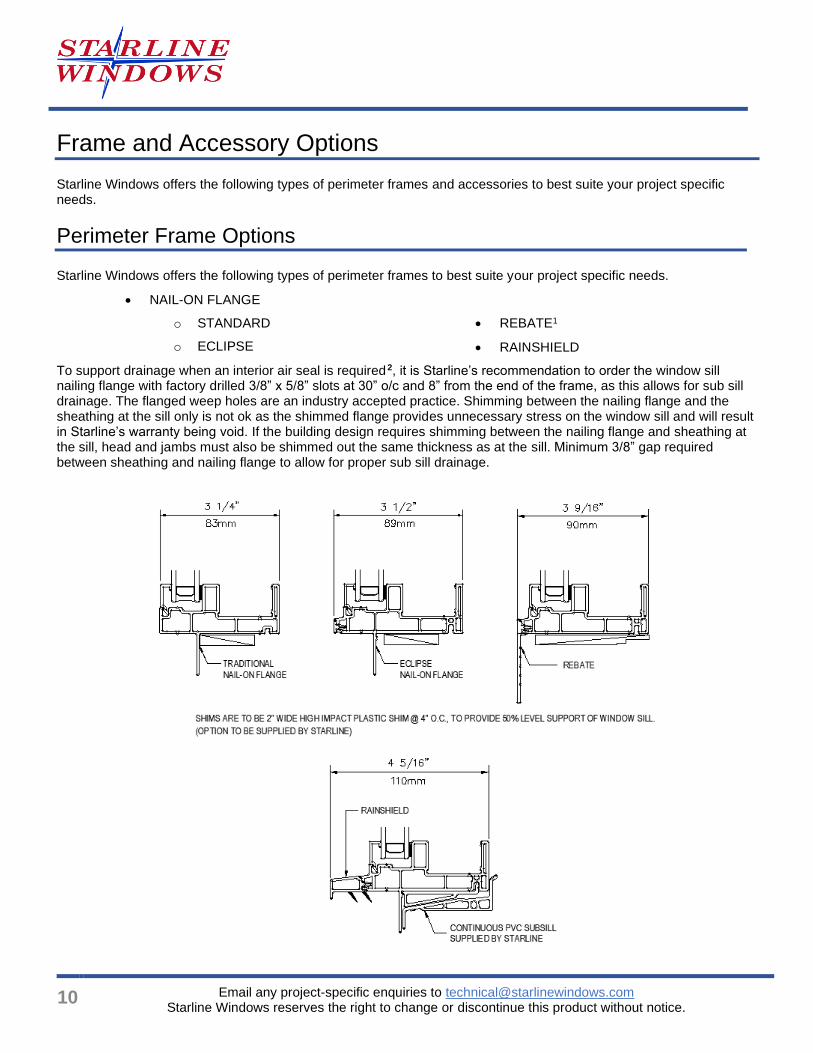
Frame and Accessory Options
Starline Windows offers the following types of perimeter frames and accessories to best suite your project specific needs.
Perimeter Frame Options
Starline Windows offers the following types of perimeter frames to best suite your project specific needs.
• NAIL-ON FLANGE
o STANDARD
o ECLIPSE
• REBATE1
• RAINSHIELD
To support drainage when an interior air seal is required 2, it is Starline’s recommendation to order the window sill
nailing flange with factory drilled 3/8” x 5/8” slots at 30” o/c and 8” from the end of the frame, as this allows for sub sill drainage. The flanged weep holes are an industry accepted practice. Shimming between the nailing flange and the sheathing at the sill only is not ok as the shimmed flange provides unnecessary stress on the window sill and will result in Starline’s warranty being void. If the building design requires shimming between the nailing flange and sheathing at the sill, head and jambs must also be shimmed out the same thickness as at the sill. Minimum 3/8” gap required between sheathing and nailing flange to allow for proper sub sill drainage.
Series 6000 Vinyl Sliding Window Design Guidelines
Email any project-specific enquiries to [email protected] Starline Windows reserves the right to change or discontinue this product without notice.
Note: Refer to the Eclipse 6000 Series – Standard Details pdf for further information. These details will provide some standard installation methods for the above frame options. These installation details are a suggested method of installation and does not necessarily represent a detail that is suitable for a specific project. To confirm project specific details, please check with your Waterproofing / Building Envelope Consultant.
1 Rebate frame is available for project specific conditions only. Please email any project specific enquiries to
2 Starline and industry best practice guidelines recommends having an interior air seal.
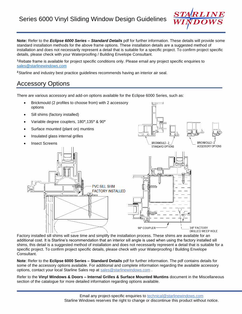
Accessory Options
There are various accessory and add-on options available for the Eclipse 6000 Series, such as:
• Brickmould (2 profiles to choose from) with 2 accessory options
• Sill shims (factory installed)
• Variable degree couplers, 180°,135° & 90°
• Surface mounted (plant on) muntins
• Insulated glass internal grilles
• Insect Screens
Factory installed sill shims will save time and simplify the installation process. These shims are available for an additional cost. It is Starline’s recommendation that an interior sill angle is used when using the factory installed sill shims, this detail is a suggested method of installation and does not necessarily represent a detail that is suitable for a specific project. To confirm project specific details, please check with your Waterproofing / Building Envelope Consultant.
Note: Refer to the Eclipse 6000 Series – Standard Details pdf for further information. The pdf contains details for some of the accessory options available. For additional and complete information regarding the available accessory options, contact your local Starline Sales rep at [email protected] .
Refer to the Vinyl Windows & Doors – Internal Grilles & Surface Mounted Muntins document in the Miscellaneous section of the catalogue for more detailed information regarding options available.
12
Email any project-specific enquiries to [email protected] Starline Windows reserves the right to change or discontinue this product without notice.
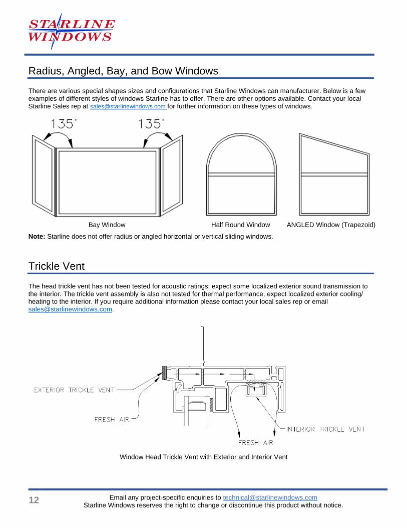
Radius, Angled, Bay, and Bow Windows
There are various special shapes sizes and configurations that Starline Windows can manufacturer. Below is a few examples of different styles of windows Starline has to offer. There are other options available. Contact your local Starline Sales rep at [email protected] for further information on these types of windows.
Bay Window Half Round Window ANGLED Window (Trapezoid)
Note: Starline does not offer radius or angled horizontal or vertical sliding windows.
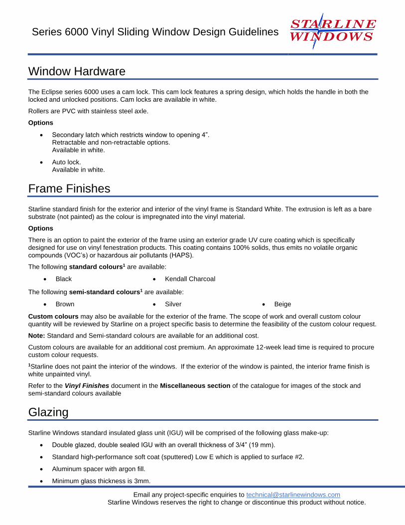
Trickle Vent
The head trickle vent has not been tested for acoustic ratings; expect some localized exterior sound transmission to the interior. The trickle vent assembly is also not tested for thermal performance, expect localized exterior cooling/ heating to the interior. If you require additional information please contact your local sales rep or email [email protected].
Window Head Trickle Vent with Exterior and Interior Vent
Series 6000 Vinyl Sliding Window Design Guidelines
Email any project-specific enquiries to [email protected] Starline Windows reserves the right to change or discontinue this product without notice.
Window Hardware
The Eclipse series 6000 uses a cam lock. This cam lock features a spring design, which holds the handle in both the locked and unlocked positions. Cam locks are available in white.
Rollers are PVC with stainless steel axle.
Options
• Secondary latch which restricts window to opening 4”. Retractable and non-retractable options. Available in white.
• Auto lock. Available in white.
Frame Finishes
Starline standard finish for the exterior and interior of the vinyl frame is Standard White. The extrusion is left as a bare substrate (not painted) as the colour is impregnated into the vinyl material.
Options
There is an option to paint the exterior of the frame using an exterior grade UV cure coating which is specifically designed for use on vinyl fenestration products. This coating contains 100% solids, thus emits no volatile organic compounds (VOC’s) or hazardous air pollutants (HAPS).
The following standard colours1 are available:
• Black • Kendall Charcoal
The following semi-standard colours1 are available:
• Brown • Silver • Beige
Custom colours may also be available for the exterior of the frame. The scope of work and overall custom colour quantity will be reviewed by Starline on a project specific basis to determine the feasibility of the custom colour request.
Note: Standard and Semi-standard colours are available for an additional cost.
Custom colours are available for an additional cost premium. An approximate 12-week lead time is required to procure custom colour requests.
1Starline does not paint the interior of the windows. If the exterior of the window is painted, the interior frame finish is white unpainted vinyl.
Refer to the Vinyl Finishes document in the Miscellaneous section of the catalogue for images of the stock and semi-standard colours available
Glazing
Starline Windows standard insulated glass unit (IGU) will be comprised of the following glass make-up:
• Double glazed, double sealed IGU with an overall thickness of 3/4” (19 mm).
• Standard high-performance soft coat (sputtered) Low E which is applied to surface #2.
• Aluminum spacer with argon fill.
• Minimum glass thickness is 3mm.
14
Email any project-specific enquiries to [email protected] Starline Windows reserves the right to change or discontinue this product without notice.
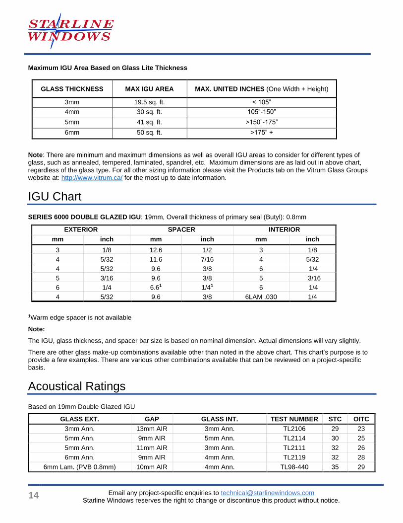
Maximum IGU Area Based on Glass Lite Thickness
GLASS THICKNESS MAX IGU AREA MAX. UNITED INCHES (One Width + Height)
3mm 19.5 sq. ft. < 105”
4mm 30 sq. ft. 105”-150”
5mm 41 sq. ft. >150”-175”
6mm 50 sq. ft. >175” +
Note: There are minimum and maximum dimensions as well as overall IGU areas to consider for different types of glass, such as annealed, tempered, laminated, spandrel, etc. Maximum dimensions are as laid out in above chart, regardless of the glass type. For all other sizing information please visit the Products tab on the Vitrum Glass Groups website at: http://www.vitrum.ca/ for the most up to date information.
IGU Chart
SERIES 6000 DOUBLE GLAZED IGU: 19mm, Overall thickness of primary seal (Butyl): 0.8mm
EXTERIOR SPACER INTERIOR
mm inch mm inch mm inch
3 1/8 12.6 1/2 3 1/8
4 5/32 11.6 7/16 4 5/32
4 5/32 9.6 3/8 6 1/4
5 3/16 9.6 3/8 5 3/16
6 1/4 6.61 1/41 6 1/4
4 5/32 9.6 3/8 6LAM .030 1/4
1Warm edge spacer is not available
Note:
The IGU, glass thickness, and spacer bar size is based on nominal dimension. Actual dimensions will vary slightly.
There are other glass make-up combinations available other than noted in the above chart. This chart’s purpose is to provide a few examples. There are various other combinations available that can be reviewed on a project-specific basis.
Acoustical Ratings
Based on 19mm Double Glazed IGU
GLASS EXT. GAP GLASS INT. TEST NUMBER STC OITC
3mm Ann. 13mm AIR 3mm Ann. TL2106 29 23
5mm Ann. 9mm AIR 5mm Ann. TL2114 30 25
5mm Ann. 11mm AIR 3mm Ann. TL2111 32 26
6mm Ann. 9mm AIR 4mm Ann. TL2119 32 28
6mm Lam. (PVB 0.8mm) 10mm AIR 4mm Ann. TL98-440 35 29
Series 6000 Vinyl Sliding Window Design Guidelines
Email any project-specific enquiries to [email protected] Starline Windows reserves the right to change or discontinue this product without notice.
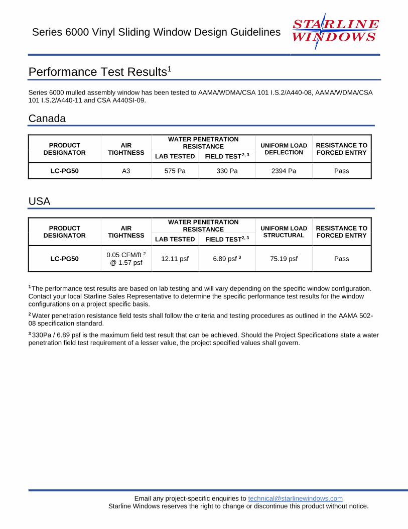
Performance Test Results1
Series 6000 mulled assembly window has been tested to AAMA/WDMA/CSA 101 I.S.2/A440-08, AAMA/WDMA/CSA 101 I.S.2/A440-11 and CSA A440SI-09.
Canada
PRODUCT DESIGNATOR
AIR TIGHTNESS
WATER PENETRATION RESISTANCE UNIFORM LOAD
DEFLECTION RESISTANCE TO FORCED ENTRY
LAB TESTED FIELD TEST 2, 3
LC-PG50 A3 575 Pa 330 Pa 2394 Pa Pass
USA
PRODUCT DESIGNATOR
AIR TIGHTNESS
WATER PENETRATION RESISTANCE UNIFORM LOAD
STRUCTURAL RESISTANCE TO FORCED ENTRY
LAB TESTED FIELD TEST2, 3
LC-PG50 0.05 CFM/ft 2
@ 1.57 psf 12.11 psf 6.89 psf 3 75.19 psf Pass
1 The performance test results are based on lab testing and will vary depending on the specific window configuration.
Contact your local Starline Sales Representative to determine the specific performance test results for the window configurations on a project specific basis.
2 Water penetration resistance field tests shall follow the criteria and testing procedures as outlined in the AAMA 502-08 specification standard.
3 330Pa / 6.89 psf is the maximum field test result that can be achieved. Should the Project Specifications state a water penetration field test requirement of a lesser value, the project specified values shall govern.
16
Email any project-specific enquiries to [email protected] Starline Windows reserves the right to change or discontinue this product without notice.
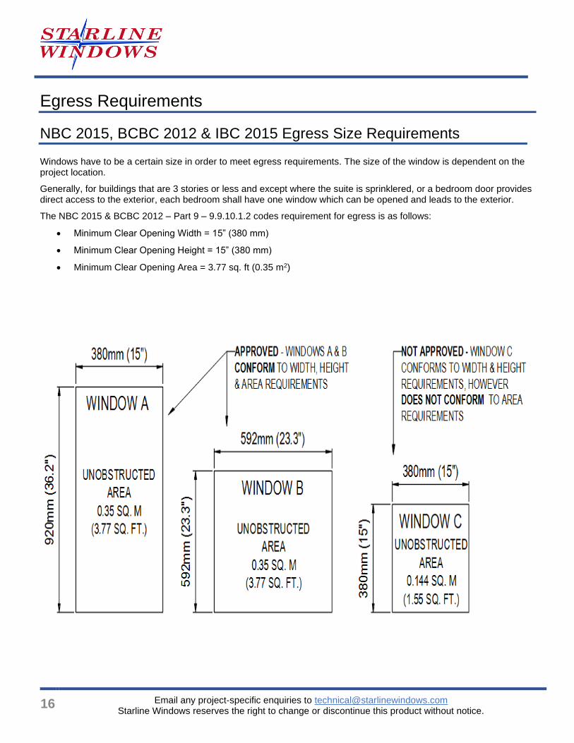
Egress Requirements
NBC 2015, BCBC 2012 & IBC 2015 Egress Size Requirements
Windows have to be a certain size in order to meet egress requirements. The size of the window is dependent on the project location.
Generally, for buildings that are 3 stories or less and except where the suite is sprinklered, or a bedroom door provides direct access to the exterior, each bedroom shall have one window which can be opened and leads to the exterior.
The NBC 2015 & BCBC 2012 – Part 9 – 9.9.10.1.2 codes requirement for egress is as follows:
• Minimum Clear Opening Width = 15” (380 mm)
• Minimum Clear Opening Height = 15” (380 mm)
• Minimum Clear Opening Area = 3.77 sq. ft (0.35 m2)
Series 6000 Vinyl Sliding Window Design Guidelines
Email any project-specific enquiries to [email protected] Starline Windows reserves the right to change or discontinue this product without notice.
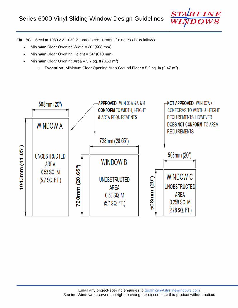
The IBC – Section 1030.2 & 1030.2.1 codes requirement for egress is as follows:
• Minimum Clear Opening Width = 20” (508 mm)
• Minimum Clear Opening Height = 24” (610 mm)
• Minimum Clear Opening Area = 5.7 sq. ft (0.53 m2)
o Exception: Minimum Clear Opening Area Ground Floor = 5.0 sq. in (0.47 m2).
18
Email any project-specific enquiries to [email protected] Starline Windows reserves the right to change or discontinue this product without notice.
Standard Size Charts
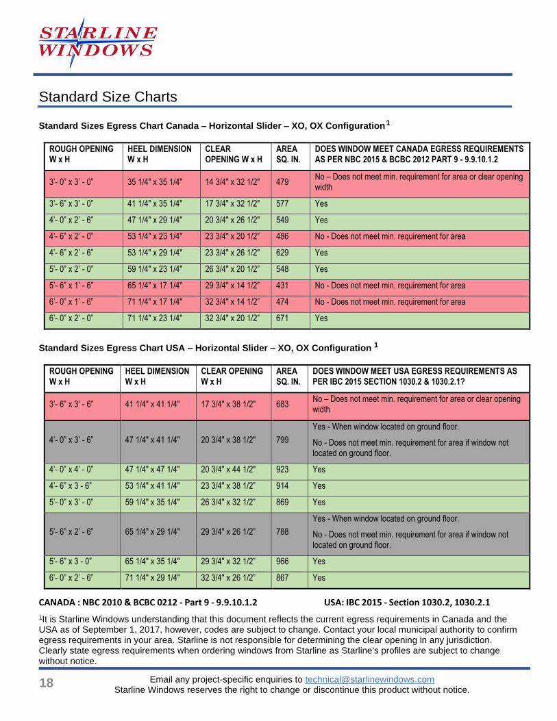
Standard Sizes Egress Chart Canada – Horizontal Slider – XO, OX Configuration
1
ROUGH OPENING W x H
HEEL DIMENSION W x H
CLEAR OPENING W x H
AREA SQ. IN.
DOES WINDOW MEET CANADA EGRESS REQUIREMENTS AS PER NBC 2015 & BCBC 2012 PART 9 - 9.9.10.1.2
3’- 0” x 3’ - 0” 35 1/4" x 35 1/4" 14 3/4" x 32 1/2" 479 No – Does not meet min. requirement for area or clear opening width
3’- 6” x 3’ - 0” 41 1/4" x 35 1/4" 17 3/4" x 32 1/2" 577 Yes
4’- 0” x 2’ - 6” 47 1/4" x 29 1/4" 20 3/4" x 26 1/2" 549 Yes
4’- 6” x 2’ - 0” 53 1/4" x 23 1/4" 23 3/4" x 20 1/2” 486 No - Does not meet min. requirement for area
4’- 6” x 2’ - 6” 53 1/4" x 29 1/4" 23 3/4" x 26 1/2" 629 Yes
5’- 0” x 2’ - 0” 59 1/4" x 23 1/4" 26 3/4" x 20 1/2” 548 Yes
5’- 6” x 1’ - 6” 65 1/4" x 17 1/4" 29 3/4" x 14 1/2” 431 No - Does not meet min. requirement for area
6’- 0” x 1’ - 6” 71 1/4" x 17 1/4" 32 3/4" x 14 1/2” 474 No - Does not meet min. requirement for area
6’- 0” x 2’ - 0” 71 1/4" x 23 1/4" 32 3/4" x 20 1/2” 671 Yes
Standard Sizes Egress Chart USA – Horizontal Slider – XO, OX Configuration 1
ROUGH OPENING W x H
HEEL DIMENSION W x H
CLEAR OPENING W x H
AREA SQ. IN.
DOES WINDOW MEET USA EGRESS REQUIREMENTS AS PER IBC 2015 SECTION 1030.2 & 1030.2.1?
3’- 6” x 3’ - 6” 41 1/4" x 41 1/4" 17 3/4" x 38 1/2" 683 No – Does not meet min. requirement for area or clear opening width
4’- 0” x 3’ - 6” 47 1/4" x 41 1/4" 20 3/4" x 38 1/2" 799
Yes - When window located on ground floor.
No - Does not meet min. requirement for area if window not located on ground floor.
4’- 0” x 4’ - 0” 47 1/4" x 47 1/4" 20 3/4" x 44 1/2" 923 Yes
4’- 6” x 3 - 6” 53 1/4" x 41 1/4" 23 3/4" x 38 1/2” 914 Yes
5’- 0” x 3’ - 0” 59 1/4" x 35 1/4" 26 3/4" x 32 1/2” 869 Yes
5’- 6” x 2’ - 6” 65 1/4" x 29 1/4" 29 3/4" x 26 1/2” 788
Yes - When window located on ground floor.
No - Does not meet min. requirement for area if window not located on ground floor.
5’- 6” x 3 - 0” 65 1/4" x 35 1/4" 29 3/4" x 32 1/2” 966 Yes
6’- 0” x 2’ - 6” 71 1/4" x 29 1/4" 32 3/4" x 26 1/2” 867 Yes
CANADA : NBC 2010 & BCBC 0212 - Part 9 - 9.9.10.1.2 USA: IBC 2015 - Section 1030.2, 1030.2.1
1It is Starline Windows understanding that this document reflects the current egress requirements in Canada and the USA as of September 1, 2017, however, codes are subject to change. Contact your local municipal authority to confirm egress requirements in your area. Starline is not responsible for determining the clear opening in any jurisdiction. Clearly state egress requirements when ordering windows from Starline as Starline's profiles are subject to change without notice.
Series 6000 Vinyl Sliding Window Design Guidelines
Email any project-specific enquiries to [email protected] Starline Windows reserves the right to change or discontinue this product without notice.
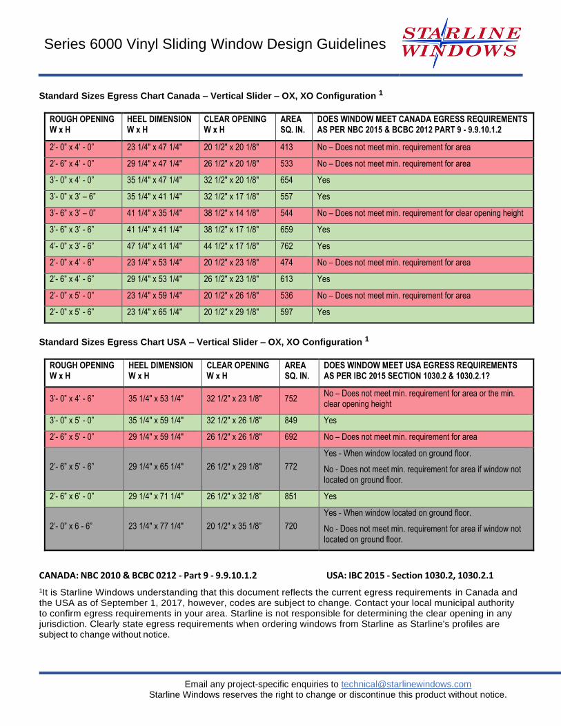
Standard Sizes Egress Chart Canada – Vertical Slider – OX, XO Configuration 1
ROUGH OPENING W x H
HEEL DIMENSION W x H
CLEAR OPENING W x H
AREA SQ. IN.
DOES WINDOW MEET CANADA EGRESS REQUIREMENTS AS PER NBC 2015 & BCBC 2012 PART 9 - 9.9.10.1.2
2’- 0” x 4’ - 0” 23 1/4" x 47 1/4" 20 1/2" x 20 1/8" 413 No – Does not meet min. requirement for area
2’- 6” x 4’ - 0” 29 1/4" x 47 1/4" 26 1/2" x 20 1/8" 533 No – Does not meet min. requirement for area
3’- 0” x 4’ - 0” 35 1/4" x 47 1/4" 32 1/2" x 20 1/8" 654 Yes
3’- 0” x 3’ – 6” 35 1/4" x 41 1/4" 32 1/2" x 17 1/8" 557 Yes
3’- 6” x 3’ – 0” 41 1/4" x 35 1/4" 38 1/2" x 14 1/8" 544 No – Does not meet min. requirement for clear opening height
3’- 6” x 3’ - 6” 41 1/4" x 41 1/4" 38 1/2" x 17 1/8" 659 Yes
4’- 0” x 3’ - 6” 47 1/4" x 41 1/4" 44 1/2" x 17 1/8" 762 Yes
2’- 0” x 4’ - 6” 23 1/4" x 53 1/4" 20 1/2" x 23 1/8" 474 No – Does not meet min. requirement for area
2’- 6” x 4’ - 6” 29 1/4" x 53 1/4" 26 1/2" x 23 1/8" 613 Yes
2’- 0” x 5’ - 0” 23 1/4" x 59 1/4" 20 1/2" x 26 1/8" 536 No – Does not meet min. requirement for area
2’- 0” x 5’ - 6” 23 1/4" x 65 1/4" 20 1/2" x 29 1/8" 597 Yes
Standard Sizes Egress Chart USA – Vertical Slider – OX, XO Configuration 1
ROUGH OPENING W x H
HEEL DIMENSION W x H
CLEAR OPENING W x H
AREA SQ. IN.
DOES WINDOW MEET USA EGRESS REQUIREMENTS AS PER IBC 2015 SECTION 1030.2 & 1030.2.1?
3’- 0” x 4’ - 6” 35 1/4" x 53 1/4" 32 1/2" x 23 1/8" 752 No – Does not meet min. requirement for area or the min. clear opening height
3’- 0” x 5’ - 0” 35 1/4" x 59 1/4" 32 1/2" x 26 1/8" 849 Yes
2’- 6” x 5’ - 0” 29 1/4" x 59 1/4" 26 1/2" x 26 1/8" 692 No – Does not meet min. requirement for area
2’- 6” x 5’ - 6” 29 1/4" x 65 1/4" 26 1/2" x 29 1/8" 772
Yes - When window located on ground floor.
No - Does not meet min. requirement for area if window not located on ground floor.
2’- 6” x 6’ - 0” 29 1/4" x 71 1/4" 26 1/2" x 32 1/8” 851 Yes
2’- 0” x 6 - 6” 23 1/4" x 77 1/4" 20 1/2" x 35 1/8” 720
Yes - When window located on ground floor.
No - Does not meet min. requirement for area if window not located on ground floor.
CANADA: NBC 2010 & BCBC 0212 - Part 9 - 9.9.10.1.2 USA: IBC 2015 - Section 1030.2, 1030.2.1
1It is Starline Windows understanding that this document reflects the current egress requirements in Canada and the USA as of September 1, 2017, however, codes are subject to change. Contact your local municipal authority to confirm egress requirements in your area. Starline is not responsible for determining the clear opening in any jurisdiction. Clearly state egress requirements when ordering windows from Starline as Starline's profiles are subject to change without notice.
20
Email any project-specific enquiries to [email protected] Starline Windows reserves the right to change or discontinue this product without notice.
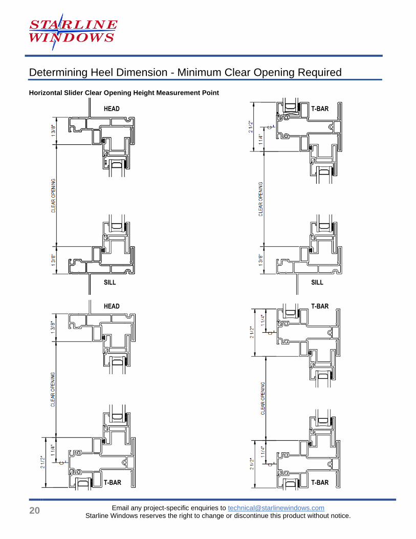
Determining Heel Dimension - Minimum Clear Opening Required
Horizontal Slider Clear Opening Height Measurement Point
HEAD T-BAR
SILL SILL
HEAD
T-BAR
T-BAR T-BAR
Series 6000 Vinyl Sliding Window Design Guidelines
Email any project-specific enquiries to [email protected] Starline Windows reserves the right to change or discontinue this product without notice.
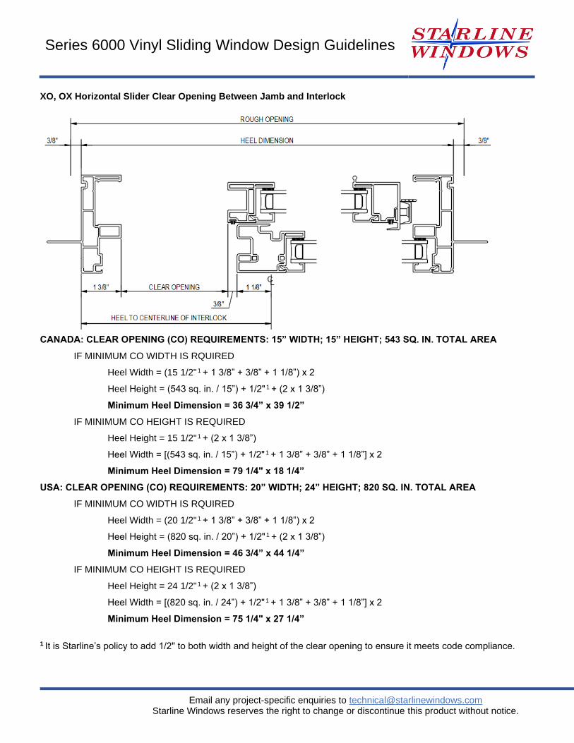
XO, OX Horizontal Slider Clear Opening Between Jamb and Interlock
CANADA: CLEAR OPENING (CO) REQUIREMENTS: 15” WIDTH; 15” HEIGHT; 543 SQ. IN. TOTAL AREA
IF MINIMUM CO WIDTH IS RQUIRED
Heel Width = (15 1/2" 1 + 1 3/8” + 3/8” + 1 1/8”) x 2
Heel Height = (543 sq. in. / 15”) + 1/2" 1 + (2 x 1 3/8”)
Minimum Heel Dimension = 36 3/4” x 39 1/2”
IF MINIMUM CO HEIGHT IS REQUIRED
Heel Height = 15 1/2" 1 + (2 x 1 3/8”)
Heel Width = [(543 sq. in. / 15”) + 1/2" 1 + 1 3/8” + 3/8” + 1 1/8”] x 2
Minimum Heel Dimension = 79 1/4" x 18 1/4”
USA: CLEAR OPENING (CO) REQUIREMENTS: 20” WIDTH; 24” HEIGHT; 820 SQ. IN. TOTAL AREA
IF MINIMUM CO WIDTH IS RQUIRED
Heel Width = (20 1/2" 1 + 1 3/8” + 3/8” + 1 1/8”) x 2
Heel Height = (820 sq. in. / 20”) + 1/2" 1 + (2 x 1 3/8”)
Minimum Heel Dimension = 46 3/4” x 44 1/4”
IF MINIMUM CO HEIGHT IS REQUIRED
Heel Height = 24 1/2" 1 + (2 x 1 3/8”)
Heel Width = [(820 sq. in. / 24”) + 1/2" 1 + 1 3/8” + 3/8” + 1 1/8”] x 2
Minimum Heel Dimension = 75 1/4" x 27 1/4”
1 It is Starline’s policy to add 1/2" to both width and height of the clear opening to ensure it meets code compliance.
22
Email any project-specific enquiries to [email protected] Starline Windows reserves the right to change or discontinue this product without notice.
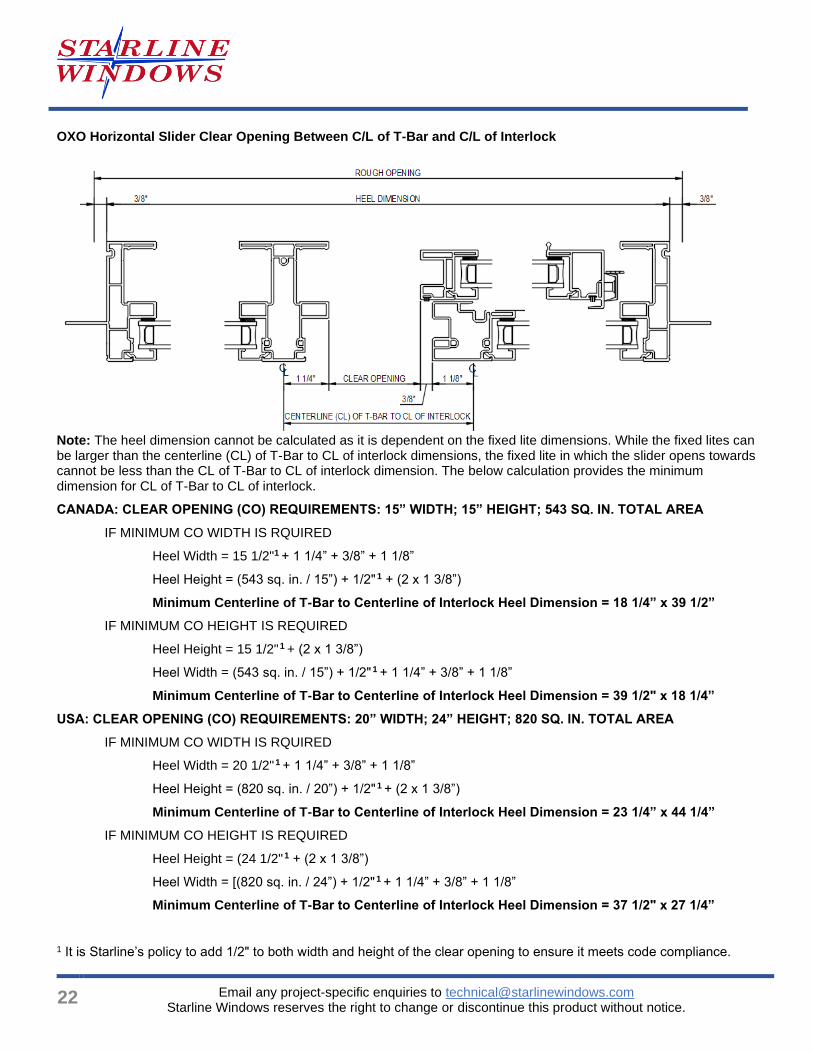
OXO Horizontal Slider Clear Opening Between C/L of T-Bar and C/L of Interlock
Note: The heel dimension cannot be calculated as it is dependent on the fixed lite dimensions. While the fixed lites can be larger than the centerline (CL) of T-Bar to CL of interlock dimensions, the fixed lite in which the slider opens towards cannot be less than the CL of T-Bar to CL of interlock dimension. The below calculation provides the minimum dimension for CL of T-Bar to CL of interlock.
CANADA: CLEAR OPENING (CO) REQUIREMENTS: 15” WIDTH; 15” HEIGHT; 543 SQ. IN. TOTAL AREA
IF MINIMUM CO WIDTH IS RQUIRED
Heel Width = 15 1/2"1 + 1 1/4” + 3/8” + 1 1/8”
Heel Height = (543 sq. in. / 15”) + 1/2" 1 + (2 x 1 3/8”)
Minimum Centerline of T-Bar to Centerline of Interlock Heel Dimension = 18 1/4” x 39 1/2”
IF MINIMUM CO HEIGHT IS REQUIRED
Heel Height = 15 1/2" 1 + (2 x 1 3/8”)
Heel Width = (543 sq. in. / 15”) + 1/2" 1 + 1 1/4” + 3/8” + 1 1/8”
Minimum Centerline of T-Bar to Centerline of Interlock Heel Dimension = 39 1/2" x 18 1/4”
USA: CLEAR OPENING (CO) REQUIREMENTS: 20” WIDTH; 24” HEIGHT; 820 SQ. IN. TOTAL AREA
IF MINIMUM CO WIDTH IS RQUIRED
Heel Width = 20 1/2" 1 + 1 1/4” + 3/8” + 1 1/8”
Heel Height = (820 sq. in. / 20”) + 1/2" 1 + (2 x 1 3/8”)
Minimum Centerline of T-Bar to Centerline of Interlock Heel Dimension = 23 1/4” x 44 1/4”
IF MINIMUM CO HEIGHT IS REQUIRED
Heel Height = (24 1/2" 1 + (2 x 1 3/8”)
Heel Width = [(820 sq. in. / 24”) + 1/2" 1 + 1 1/4” + 3/8” + 1 1/8”
Minimum Centerline of T-Bar to Centerline of Interlock Heel Dimension = 37 1/2" x 27 1/4”
1 It is Starline’s policy to add 1/2" to both width and height of the clear opening to ensure it meets code compliance.
Series 6000 Vinyl Sliding Window Design Guidelines
Email any project-specific enquiries to [email protected] Starline Windows reserves the right to change or discontinue this product without notice.
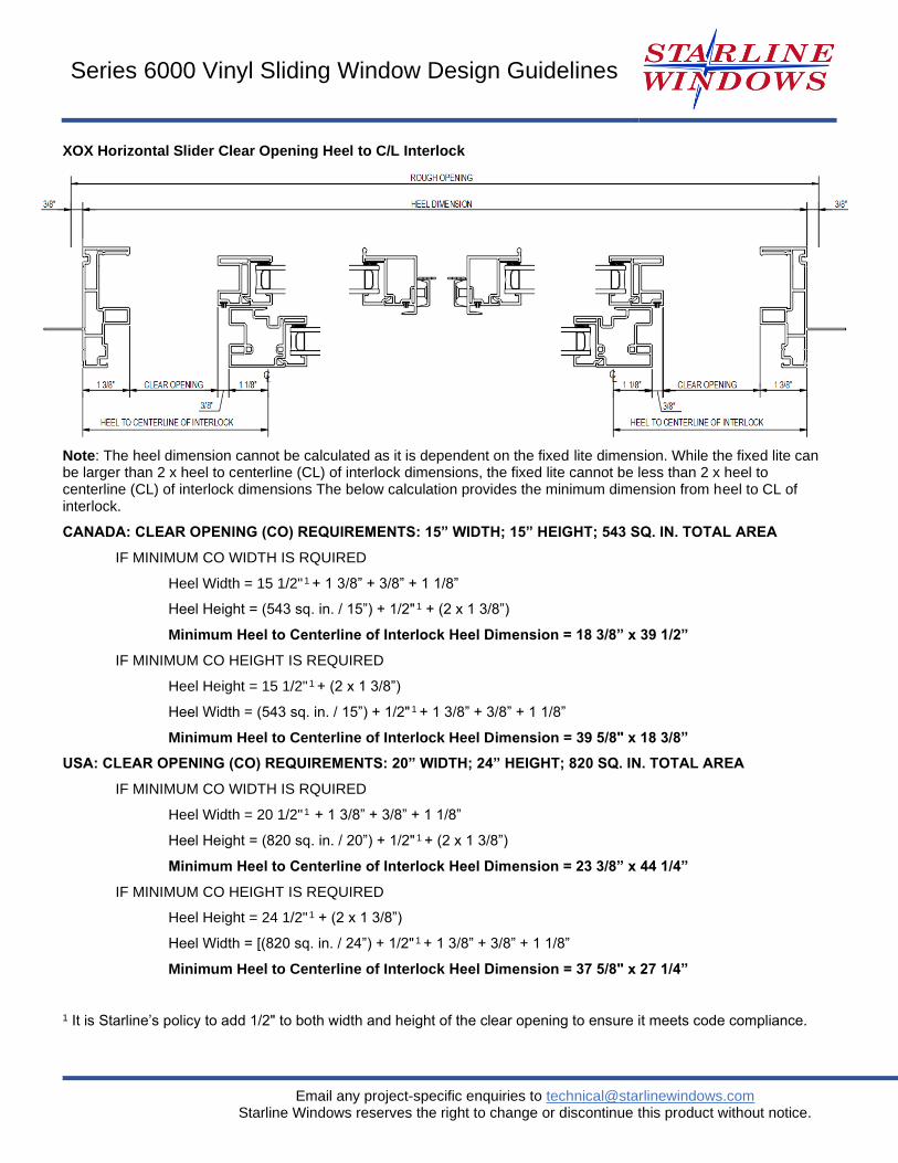
XOX Horizontal Slider Clear Opening Heel to C/L Interlock
Note: The heel dimension cannot be calculated as it is dependent on the fixed lite dimension. While the fixed lite can be larger than 2 x heel to centerline (CL) of interlock dimensions, the fixed lite cannot be less than 2 x heel to centerline (CL) of interlock dimensions The below calculation provides the minimum dimension from heel to CL of interlock.
CANADA: CLEAR OPENING (CO) REQUIREMENTS: 15” WIDTH; 15” HEIGHT; 543 SQ. IN. TOTAL AREA
IF MINIMUM CO WIDTH IS RQUIRED
Heel Width = 15 1/2" 1 + 1 3/8” + 3/8” + 1 1/8”
Heel Height = (543 sq. in. / 15”) + 1/2" 1 + (2 x 1 3/8”)
Minimum Heel to Centerline of Interlock Heel Dimension = 18 3/8” x 39 1/2”
IF MINIMUM CO HEIGHT IS REQUIRED
Heel Height = 15 1/2" 1 + (2 x 1 3/8”)
Heel Width = (543 sq. in. / 15”) + 1/2" 1 + 1 3/8” + 3/8” + 1 1/8”
Minimum Heel to Centerline of Interlock Heel Dimension = 39 5/8" x 18 3/8”
USA: CLEAR OPENING (CO) REQUIREMENTS: 20” WIDTH; 24” HEIGHT; 820 SQ. IN. TOTAL AREA
IF MINIMUM CO WIDTH IS RQUIRED
Heel Width = 20 1/2" 1 + 1 3/8” + 3/8” + 1 1/8”
Heel Height = (820 sq. in. / 20”) + 1/2" 1 + (2 x 1 3/8”)
Minimum Heel to Centerline of Interlock Heel Dimension = 23 3/8” x 44 1/4”
IF MINIMUM CO HEIGHT IS REQUIRED
Heel Height = 24 1/2" 1 + (2 x 1 3/8”)
Heel Width = [(820 sq. in. / 24”) + 1/2" 1 + 1 3/8” + 3/8” + 1 1/8”
Minimum Heel to Centerline of Interlock Heel Dimension = 37 5/8" x 27 1/4”
1 It is Starline’s policy to add 1/2" to both width and height of the clear opening to ensure it meets code compliance.
24
Email any project-specific enquiries to [email protected] Starline Windows reserves the right to change or discontinue this product without notice.
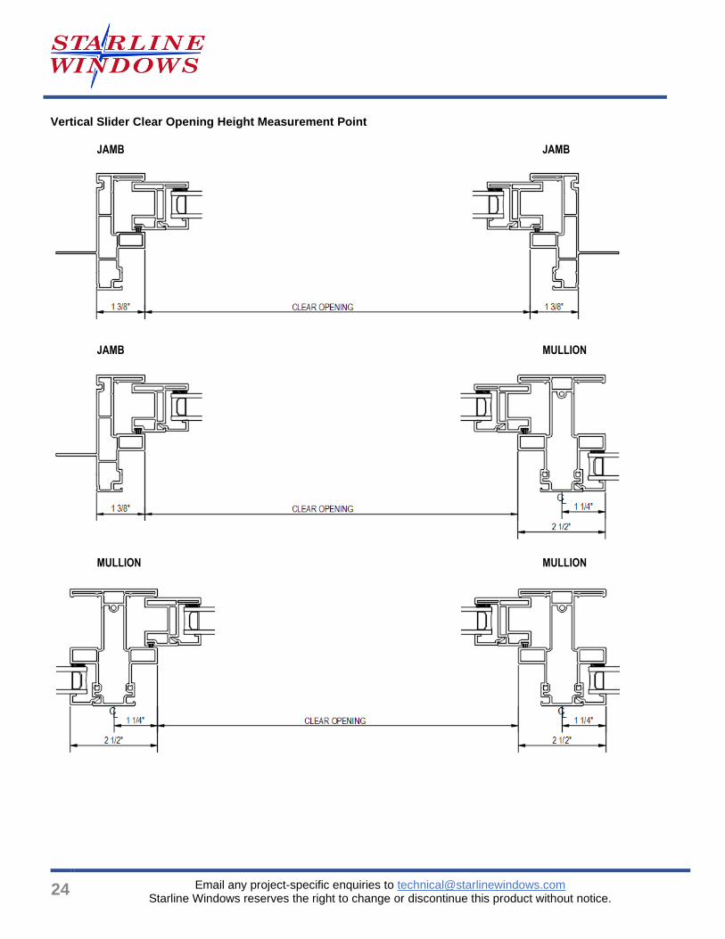
Vertical Slider Clear Opening Height Measurement Point
JAMB JAMB
JAMB MULLION
MULLION MULLION
Series 6000 Vinyl Sliding Window Design Guidelines
Email any project-specific enquiries to [email protected] Starline Windows reserves the right to change or discontinue this product without notice.
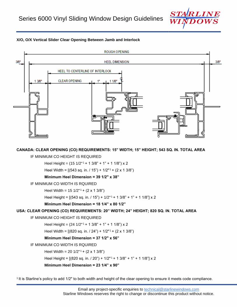
X/O, O/X Vertical Slider Clear Opening Between Jamb and Interlock
CANADA: CLEAR OPENING (CO) REQUIREMENTS: 15” WIDTH; 15” HEIGHT; 543 SQ. IN. TOTAL AREA
IF MINIMUM CO HEIGHT IS REQUIRED
Heel Height = (15 1/2" 1 + 1 3/8” + 1” + 1 1/8”) x 2
Heel Width = [(543 sq. in. / 15”) + 1/2" 1 + (2 x 1 3/8”)
Minimum Heel Dimension = 39 1/2" x 38”
IF MINIMUM CO WIDTH IS RQUIRED
Heel Width = 15 1/2" 1 + (2 x 1 3/8”)
Heel Height = [(543 sq. in. / 15”) + 1/2" 1 + 1 3/8” + 1” + 1 1/8”] x 2
Minimum Heel Dimension = 18 1/4” x 80 1/2”
USA: CLEAR OPENING (CO) REQUIREMENTS: 20” WIDTH; 24” HEIGHT; 820 SQ. IN. TOTAL AREA
IF MINIMUM CO HEIGHT IS REQUIRED
Heel Height = (24 1/2" 1 + 1 3/8” + 1” + 1 1/8”) x 2
Heel Width = [(820 sq. in. / 24”) + 1/2" 1 + (2 x 1 3/8”)
Minimum Heel Dimension = 37 1/2" x 56”
IF MINIMUM CO WIDTH IS RQUIRED
Heel Width = 20 1/2" 1 + (2 x 1 3/8”)
Heel Height = [(820 sq. in. / 20”) + 1/2" 1 + 1 3/8” + 1” + 1 1/8”] x 2
Minimum Heel Dimension = 23 1/4” x 90”
1 It is Starline’s policy to add 1/2" to both width and height of the clear opening to ensure it meets code compliance.
26
Email any project-specific enquiries to [email protected] Starline Windows reserves the right to change or discontinue this product without notice.
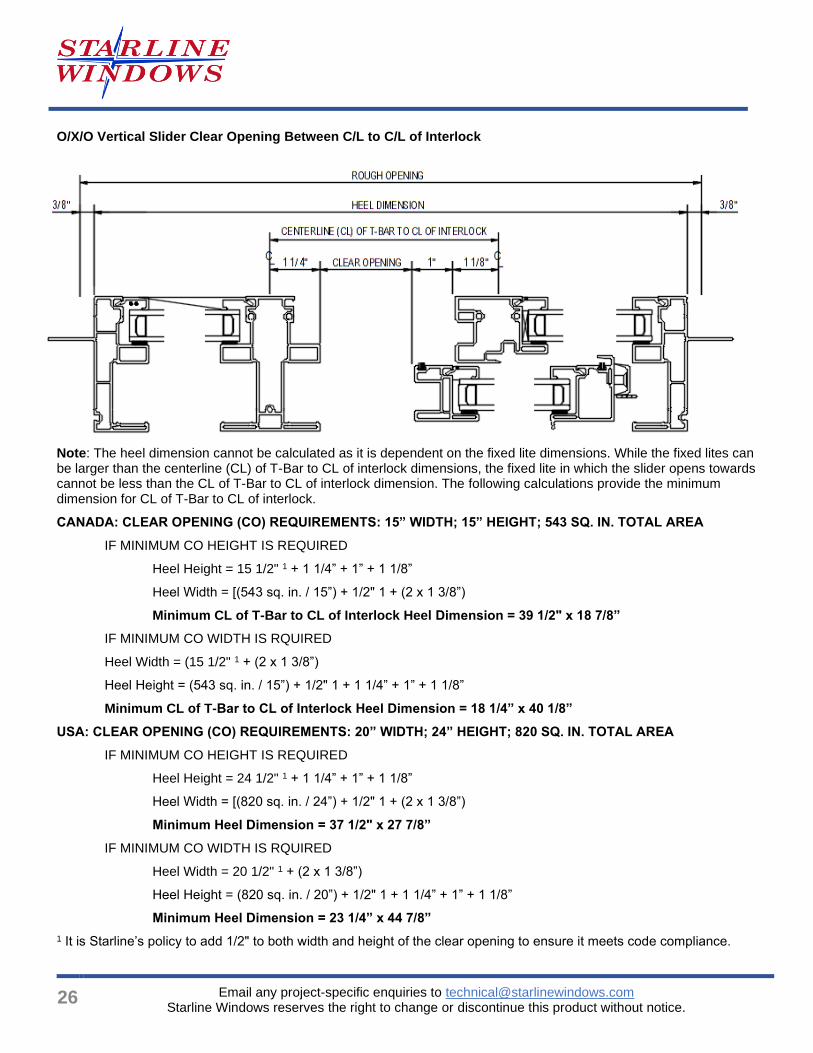
O/X/O Vertical Slider Clear Opening Between C/L to C/L of Interlock
Note: The heel dimension cannot be calculated as it is dependent on the fixed lite dimensions. While the fixed lites can be larger than the centerline (CL) of T-Bar to CL of interlock dimensions, the fixed lite in which the slider opens towards cannot be less than the CL of T-Bar to CL of interlock dimension. The following calculations provide the minimum dimension for CL of T-Bar to CL of interlock.
CANADA: CLEAR OPENING (CO) REQUIREMENTS: 15” WIDTH; 15” HEIGHT; 543 SQ. IN. TOTAL AREA
IF MINIMUM CO HEIGHT IS REQUIRED
Heel Height = 15 1/2" 1 + 1 1/4” + 1” + 1 1/8”
Heel Width = [(543 sq. in. / 15”) + 1/2" 1 + (2 x 1 3/8”)
Minimum CL of T-Bar to CL of Interlock Heel Dimension = 39 1/2" x 18 7/8”
IF MINIMUM CO WIDTH IS RQUIRED
Heel Width = (15 1/2" 1 + (2 x 1 3/8”)
Heel Height = (543 sq. in. / 15”) + 1/2" 1 + 1 1/4” + 1” + 1 1/8”
Minimum CL of T-Bar to CL of Interlock Heel Dimension = 18 1/4” x 40 1/8”
USA: CLEAR OPENING (CO) REQUIREMENTS: 20” WIDTH; 24” HEIGHT; 820 SQ. IN. TOTAL AREA
IF MINIMUM CO HEIGHT IS REQUIRED
Heel Height = 24 1/2" 1 + 1 1/4” + 1” + 1 1/8”
Heel Width = [(820 sq. in. / 24”) + 1/2" 1 + (2 x 1 3/8”)
Minimum Heel Dimension = 37 1/2" x 27 7/8”
IF MINIMUM CO WIDTH IS RQUIRED
Heel Width = 20 1/2" 1 + (2 x 1 3/8”)
Heel Height = (820 sq. in. / 20”) + 1/2" 1 + 1 1/4” + 1” + 1 1/8”
Minimum Heel Dimension = 23 1/4” x 44 7/8”
1 It is Starline’s policy to add 1/2" to both width and height of the clear opening to ensure it meets code compliance.
Series 6000 Vinyl Sliding Window Design Guidelines
Email any project-specific enquiries to [email protected] Starline Windows reserves the right to change or discontinue this product without notice.
Determining Clear Opening Based on Heel Dimension Provided
CANADA: CLEAR OPENING (CO) REQUIREMENTS: 15” WIDTH; 15” HEIGHT; 543 SQ. IN. TOTAL AREA
XO, OX HORIZONTAL SLIDER
Clear Opening Width = (Heel Dimension / 2) – 2.875”
Clear Opening Height = Heel Dimension – 2.75”
OXO HORIZONTAL SLIDER
Clear Opening Width = C/L of T-Bar to C/L of Interlock Heel Dimension – 2.75”
Clear Opening Height = Heel Dimension – 2.75”
XOX HORIZONTAL SLIDER
Clear Opening Width = Heel to C/L of T-Bar – 2.875”
Clear Opening Height = Heel Dimension – 2.75”
XO, OX VERTICAL SLIDER
Clear Opening Height = (Heel Dimension / 2) – 3.5"
Clear Opening Width = Heel Dimension – 2.75”
OXO VERTICAL SLIDER
Clear Opening Height = C/L of T-Bar to C/L of Interlock Heel Dimension – 3.375”
Clear Opening Width = Heel Dimension – 2.75”
NOTE: No clear opening dimension can be smaller than 15 1/2" in either the width or the height as it is Starline’s policy to manufacturer to a 1/2" larger dimension than minimum code requirement while also ensuring a minimum area for the clear opening is 543 sq. in. or greater.
28
Email any project-specific enquiries to [email protected] Starline Windows reserves the right to change or discontinue this product without notice.
Product Specification 08 53 13 – Vinyl Windows
Note: Bolded text in this specification are options that are highlighted for the specifier to select or to list requirements.
Part 1 - General
A fully welded 3 1/2" PVC window frame designed for single family homes, townhouses, residential low and midrise construction and institutional projects. 1
1 Note to specifier: Frame depth depends on frame type selected. Nail-on Flange, Rebate, and Rainshield frame depths vary. Above frame depth is based on Starline’s standard Nail-on Flange frame. If a frame type other than Nail-on Flange is selected, contact [email protected] for further information.
1.1 Summary
A. Section Includes: Vinyl Windows:
1. Vinyl fixed and/or horizontal sliding and/or vertical sliding windows complete with Nail-on Flange (Eclipse or traditional) and /or Rebate and / or Rainshield frame to be Starline’s Eclipse 6000 Series window manufactured by Starline Windows Ltd.
2. Work included: Furnish labor, material and other services to complete the fabrication and installation of the windows, including all materials and fitments required for the operation of the units in the manner, direction and performance shown on the shop drawings and specified herein.
Work not included: Structural support of window framing, interior trims. (Specifier list others).
Related work specified elsewhere: (Specifier to list).
B. Related Sections: (Specifier to select the following related sections)
1. 07 27 00 – Air Barriers
2. 07 60 00 – Flashing and Trim
3. 07 92 00 – Joint Sealants
4. 08 15 23 – Vinyl-Framed Glass Swing Doors
5. 08 32 13 – Sliding Vinyl-Framed Glass Doors
6. 08 80 00 – Glazing
1.2 Quality Assurance
A. Drawings and specifications for Work of this Section are based upon the Eclipse 6000 Punched Windows manufactured by Starline Windows. Whenever alternative products are offered, submit supporting technical literature, samples, drawings and performance data for comparison 10 days prior to closing date. Test reports must be made available on request.
B. Windows shall be tested and conform to the AAMA/WDMA/CSA 101 I.S.2/A440-08, AAMA/WDMA/CSA 101 I.S.2/A440-11, and CSA A440SI-09 requirements.
C. Manufacturer Qualifications:
1. Manufacturer to have a minimum 10 years of documented experience.
Series 6000 Vinyl Sliding Window Design Guidelines
Email any project-specific enquiries to [email protected] Starline Windows reserves the right to change or discontinue this product without notice.
2. Manufacturer capable of providing an aluminum window system that meet or exceed the performance requirements indicated.
3. Manufacturer capable of providing field representation during window installation.
D. Installer Qualifications: Installer performing the Work in this Section to have a minimum of 3 years documented experience and approved by the manufacturer.
E. Mock-Up: If requested by Consultant, a mock up is to be provided and installed at project site. Mock-up to include acceptable products and manufacturer approved installation methods. Obtain Owner's and Consultant’s acceptance of finish color, and workmanship standard.
1.3 Structural requirements 1
Specifier to select or remove section depending if project is engineered.
A. Limit mullion deflection to L/175.
B. Allow for deflection of building structure. Vinyl windows shall be designed, fabricated and installed to withstand slab edge vertical differential deflections of maximum 3/4”2 and seismic inter-story lateral drift movements of elastic +/- 3/8”1 without significant damage to the fenestration system or in-elastic +/- 1 3/4” 1 with significant damage expected but framing to be designed to remain anchored to the structure.
1 Note to specifier: This section is only applicable if there is a Professional Engineer involved with the project.
2 Values may change based on the configuration of the windows. Values to be specified by a Professional Engineer.
1.4 Test and Performance Requirements
Specifier to select from the following performance requirements.
A. Fixed window wall shall meet performance class LC-PG50 when tested to AAMA/WDMA/CSA 101 I.S.2/A440-08, AAMA/WDMA/CSA 101 I.S.2/A440-11, and CSA A440SI-09:
1. Air Infiltration: Fixed window air infiltration shall not exceed 0.05 cfm/ft2 (A3) when tested in accordance with ASTM E 283 with a pressure difference of 1.57 psf / 75 Pa.
2. Water Penetration Resistance:
I. There shall be no water infiltration for fixed windows when tested in accordance with ASTM E547 with a pressure difference of 12.11 psf / 575 Pa (Laboratory Test).
II. There shall be no water infiltration for fixed windows when tested in accordance with AAMA 502-08 with a pressure difference up to a maximum of 6.89 psf / 330 Pa (Field Test) 2
3. Uniform Load Deflection Test: The deflection of fixed window shall not exceed L/175 and there shall be no permanent set when tested in accordance with ASTM E330 with a design pressure of 50 psf / 2394 Pa, positive and negative.
4. Uniform Load Structural Test: There shall be no damage to hardware, accessories, fasteners, or any other damage that would render the window in operable when tested in accordance with ASTM E330 with a structural test pressure of 75.19 psf / 3600 Pa, positive and negative.
5. Thermal Performance3
I. U-value: The maximum fixed window thermal transmittance U-value shall be 0.28 BTU/ hr*ft2*°F (1.59 W/m2*k) when tested in accordance with AAMA 1503.1 and CAN/CSA-A440.2. Windows shall be tested and labeled to N.F.R.C. standard 100 & 200.
II. Solar Heat Gain Coefficient: A (maximum or minimum) of 0.36.
III. Visible Light Transmittance: A (maximum or minimum) of 0.65.
30
Email any project-specific enquiries to [email protected] Starline Windows reserves the right to change or discontinue this product without notice.
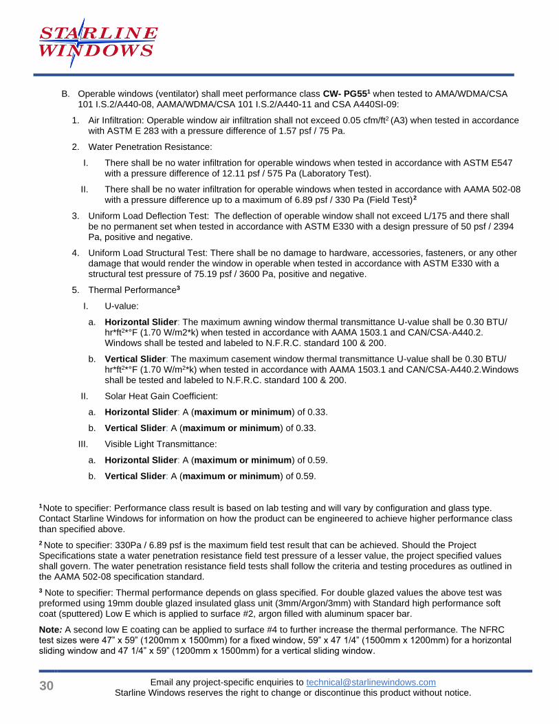
B. Operable windows (ventilator) shall meet performance class CW- PG551 when tested to AMA/WDMA/CSA 101 I.S.2/A440-08, AAMA/WDMA/CSA 101 I.S.2/A440-11 and CSA A440SI-09:
1. Air Infiltration: Operable window air infiltration shall not exceed 0.05 cfm/ft2 (A3) when tested in accordance with ASTM E 283 with a pressure difference of 1.57 psf / 75 Pa.
2. Water Penetration Resistance:
I. There shall be no water infiltration for operable windows when tested in accordance with ASTM E547 with a pressure difference of 12.11 psf / 575 Pa (Laboratory Test).
II. There shall be no water infiltration for operable windows when tested in accordance with AAMA 502-08 with a pressure difference up to a maximum of 6.89 psf / 330 Pa (Field Test)
2
3. Uniform Load Deflection Test: The deflection of operable window shall not exceed L/175 and there shall be no permanent set when tested in accordance with ASTM E330 with a design pressure of 50 psf / 2394 Pa, positive and negative.
4. Uniform Load Structural Test: There shall be no damage to hardware, accessories, fasteners, or any other damage that would render the window in operable when tested in accordance with ASTM E330 with a structural test pressure of 75.19 psf / 3600 Pa, positive and negative.
5. Thermal Performance3
I. U-value:
a. Horizontal Slider: The maximum awning window thermal transmittance U-value shall be 0.30 BTU/ hr*ft2*°F (1.70 W/m2*k) when tested in accordance with AAMA 1503.1 and CAN/CSA-A440.2. Windows shall be tested and labeled to N.F.R.C. standard 100 & 200.
b. Vertical Slider: The maximum casement window thermal transmittance U-value shall be 0.30 BTU/ hr*ft2*°F (1.70 W/m2*k) when tested in accordance with AAMA 1503.1 and CAN/CSA-A440.2.Windows shall be tested and labeled to N.F.R.C. standard 100 & 200.
II. Solar Heat Gain Coefficient:
a. Horizontal Slider: A (maximum or minimum) of 0.33.
b. Vertical Slider: A (maximum or minimum) of 0.33.
III. Visible Light Transmittance:
a. Horizontal Slider: A (maximum or minimum) of 0.59.
b. Vertical Slider: A (maximum or minimum) of 0.59.
1 Note to specifier: Performance class result is based on lab testing and will vary by configuration and glass type.
Contact Starline Windows for information on how the product can be engineered to achieve higher performance class than specified above.
2 Note to specifier: 330Pa / 6.89 psf is the maximum field test result that can be achieved. Should the Project Specifications state a water penetration resistance field test pressure of a lesser value, the project specified values shall govern. The water penetration resistance field tests shall follow the criteria and testing procedures as outlined in the AAMA 502-08 specification standard.
3 Note to specifier: Thermal performance depends on glass specified. For double glazed values the above test was preformed using 19mm double glazed insulated glass unit (3mm/Argon/3mm) with Standard high performance soft coat (sputtered) Low E which is applied to surface #2, argon filled with aluminum spacer bar.
Note: A second low E coating can be applied to surface #4 to further increase the thermal performance. The NFRC test sizes were 47” x 59” (1200mm x 1500mm) for a fixed window, 59” x 47 1/4” (1500mm x 1200mm) for a horizontal sliding window and 47 1/4” x 59” (1200mm x 1500mm) for a vertical sliding window.

Series 6000 Vinyl Sliding Window Design Guidelines
Email any project-specific enquiries to [email protected] Starline Windows reserves the right to change or discontinue this product without notice.
1.5 Submittals
A. Product Data: Submit complete product data on system being used.
B. Samples: Submit glass and frame colour(s) samples.
C. Close-out Submittals:
1. Warranty: Submit executed Manufacturer’s warranty.
2. Project Record Documents: Submit operation and maintenance data for installed product in accordance with General Conditions.
Part 2 – Products
2.1 Manufacturers
A. Acceptable Manufacturers: Starline Windows
1. Vinyl Windows (Punched Opening): Eclipse 6000 Series
B. Substitutions: Approved alternates
2.2 Material
A. Vinyl Extrusion:
1. 89 mm (3 1/2") deep perimeter frame member 1.
2. Multi-chamber for strength and thermal performance with a nominal wall thickness of 1.93mm (0.078”).
3. Frame member and intermediate bars 100% uPVC and is UV stabilized for optimum outdoor performance.
B. Fasteners: Stainless steel and / or steel coated with Leland DT200 coating and of sufficient size and quantity to perform their intended function.
C. Weather-stripping: Finseal material.
D. Glass Setting Blocks: FPVC, Neoprene, EPDM, Santoprene or silicone with an 80 to 90 Shore A durometer hardness. Block material shall be compatible with sealed unit edge sealant.
E. Glazing bead: uPVC and glazed from the outside.
F. Glazing tape: Foam tape.
2.3 Fabrication
A. Fabricate framing from extrusions of size and shape shown on approved shop drawings or approved signed order if shop drawings are not applicable.
B. Main framing and operable sash (ventilator) extrusions shall be welded mitre corner construction.
C. Intermediate mullions and T-Bars shall be butt jointed and gasketed, mechanically screwed and sealed to the main perimeter frame.
D. All framing profiles shall be straight and free of deformations and defects.
E. Joints shall be accurately machined, fitted and sealed.
F. Coupling mullions shall be designed to provide a functional split to permit modular construction and allow for thermal expansion.
32
Email any project-specific enquiries to [email protected] Starline Windows reserves the right to change or discontinue this product without notice.
G. Perimeter frame shall be 89mm (3 1/2”) deep with a minimum wall thickness of 2mm (0.078") and be thermally broken.1
H. Operable window (ventilator) shall be 33mm (1 5/16") deep with a minimum wall thickness of 2mm (0.078") and be thermally broken.
I. All interior joints and interior screw heads shall be sealed with a non-hardening sealant.
J. Sliding ventilator shall have a single Mohair weather strip with fin seal. Weather stripping will be white when a white, beige or silver exterior frame colour is used and weather stripping will be black when a brown, charcoal or black frame is used.
K. All glazing pockets shall be vented, pressure equalized, and drained to the outside.
L. Glass bead shall be uPVC and a snap-in screw less type.
1 Note to specifier: Frame depth depends on frame type selected. Nail-flange, Rebate and Rainshield frame depths
vary. Above frame depth is based on Starline’s standard Nail-on flange frame.
2.4 Glazing1
A. Double glazed, double seal insulated glass unit (IGU) with an overall thickness of 3/4” (19 mm).
B. Standard high-performance soft coat (sputtered) Low E applied to surface #2.
C. Aluminum spacer with argon fill.
D. Glass thickness shall be 3mm. Glass thickness and quality shall conform to the requirements of the U.S.A. and Canadian Code for commercial construction, current edition.
E. Where practical, glazing shall be installed at the factory before shipping to site.
1 Note to specifier: Glazing noted above is based on Starline Windows standard product offering. There are various other options available. See 2.7.A. of this specification.
2.5 Hardware1
A. Hardware for the vinyl operable sash (ventilator) and window frames shall be furnished by the window manufacturer.
B. Where practical, all hardware fittings shall be installed at the factory before shipping to site.
C. Hardware shall be as follows:
1. Sliding operable sash (ventilator) slides on PVC rollers that have a stainless-steel axle.
2. Cam lock with spring design. The spring design holds the handle in locked and unlocked positions. Cam locks are PVC and are available in white.
1 Note to specifier: Hardware noted above is based on Starline Windows standard product offering. There are various other options available. Refer to 2.7.F of this specification.
2.6 Frame Finish
A. All exposed surfaces of vinyl window and framing members shall be free of scratches and other serious surface blemishes.
B. Finish: Standard white on the exterior and interior1.
1 Note to Specifier: Option to have dual frame colour; Painted colour on the exterior of the window only. The interior of the window is always white. Should an exterior colour be required, refer to 2.7.D. of this specification.
Series 6000 Vinyl Sliding Window Design Guidelines
Email any project-specific enquiries to [email protected] Starline Windows reserves the right to change or discontinue this product without notice.
2.7 Optional Items
Specifier to select from the following options and remove options not being selected
A. Glazing
1. 4mm, 5mm, 6mm and greater thickness available.
2. Tinted, obscured & reflective glass
3. Laminated glass
4. Insulated glass internal grilles
5. Surface mounted (plant-on) muntins.
6. Spacer bars
i. Aluminum spacer bar
ii. Black aluminum spacer bar
B. Coupling mullions – Range of couplers are available, i.e.: 180°, 135° (Bay), variable degree, ect.
C. Extruded aluminum head flashing
D. Dual frame color upgrade options – 1 color on exterior and white on the interior:
1. UV cure coating 1: UV cure coating on the exterior with white interior.
Black Brown Silver
Kendall Charcoal Beige
2. Custom colours2 may be available. Virtually any colour can be matched or very closely matched. The scope of work and overall custom colour quantity will be reviewed by Starline on a project specific basis to determine the feasibility of the custom colour request.
E. Shop Drawings: Submit complete shop drawings which include floor plans, elevations, window schedule, and product components including anchorage, fasteners, accessories and finish colour
1. Non-engineered shop drawings.
2. Engineered shop drawings, stamped and sealed by professional engineer.
F. Hardware:
1. Secondary latch which restricts window to opening 4”. Retractable and non-retractable options. Available in white.
2. Auto lock. Available in white.
G. Sill Shim (Factory Installed).
H. Protection: Insulated Glass Unit shall be protected with smart guard on the exterior and / or interior.
I. Insect Screens: Frames are made from extruded aluminum and are rigidly joined at the corners. Aluminum frame shall be finished to match interior window frame colour. Screen shall be black fiber mesh. Screens are held in place with clips.
1 Note to Specifier: UV colours are available for an additional cost premium.
2 Custom colours are available for an additional cost premium. An approximate 12-week lead time is required to procure custom colour requests.
34
Email any project-specific enquiries to [email protected] Starline Windows reserves the right to change or discontinue this product without notice.
Part 3 - Execution
3.1 Examination
A. Installer to examine openings, structural support, substrates and any other conditions that would affect the installation, for compliance with manufacturer’s instructions.
B. Verify rough opening dimensions.
C. Verify sill is within tolerance of levelness to ensure adequate shimming to obtain proper drainage.
3.2 Installation
A. Install manufacturer’s system in accordance with manufacturer’s approved shop drawings.
B. Windows shall be installed and adjusted by experienced personnel in accordance with the manufacturer instructions and approved shop drawings.
C. All items in this section shall be set in their correct location and shall be set level, square, plumb and at proper elevations and in alignment with other work.
3.3 Field Quality and Control
A. Manufacturer’s Field Services: Upon Owner and/or Consultants written request, provide manufacturer’s field service representative for site visit to inspect installation and to ensure accordance with manufacturer’s instruction and approved shop drawings.
B. Field Tests: Owner and/or Consultant may choose to conduct tests for water penetration and air infiltration.
1. Testing Standard per AAMA 502.
2. Field testing shall be performed by a qualified independent testing agency.
3. Field testing should not occur until the window has been installed and the caulking is cured. Ensure the products used to complete building envelope tie in (membrane, caulking, flashing, cladding, etc.) are installed complete and have cured.
3.4 Protection and Cleaning
A. Protection: Windows shall be isolated from concrete, mortar, plaster and dissimilar metals with bituminous paint or other isolation coatings.
B. Cleaning: It shall be the responsibility of the General Contractor to maintain protection and provide final cleaning.
Note: This specification is intended to be used by a qualified Specifier and will require modifications for the project specific requirements. This specification is not intended to be use verbatim as the project specific specification.
Laws, building and safety codes governing the design and use of this product vary widely. Starline Windows does not control the selection and use of this product and assumes no responsibility therefor.
Series 6000 Vinyl Sliding Window Design Guidelines
Email any project-specific enquiries to [email protected] Starline Windows reserves the right to change or discontinue this product without notice.
35
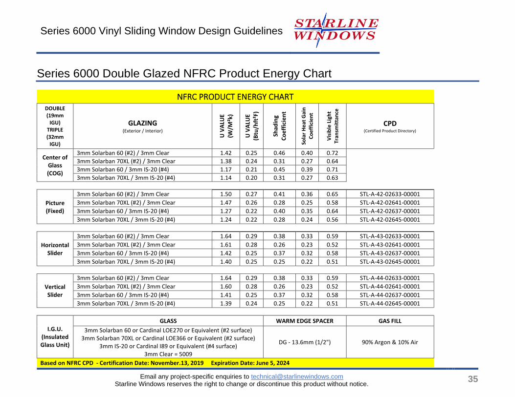
Series 6000 Double Glazed NFRC Product Energy Chart
NFRC PRODUCT ENERGY CHART DOUBLE (19mm
IGU) TRIPLE (32mm
IGU)
GLAZING (Exterior / Interior)
U V
ALU
E
(W/M
²k)
U V
ALU
E
(Btu
/hft
²F)
Shad
ing
Co
eff
icie
nt
Sola
r H
eat
Gai
n
Co
eff
icie
nt
Vis
ible
Lig
ht
Tran
smit
tan
ce
CPD (Certified Product Directory)
Center of Glass (COG)
3mm Solarban 60 (#2) / 3mm Clear 1.42 0.25 0.46 0.40 0.72
3mm Solarban 70XL (#2) / 3mm Clear 1.38 0.24 0.31 0.27 0.64
3mm Solarban 60 / 3mm IS-20 (#4) 1.17 0.21 0.45 0.39 0.71
3mm Solarban 70XL / 3mm IS-20 (#4) 1.14 0.20 0.31 0.27 0.63
Picture (Fixed)
3mm Solarban 60 (#2) / 3mm Clear 1.50 0.27 0.41 0.36 0.65 STL-A-42-02633-00001
3mm Solarban 70XL (#2) / 3mm Clear 1.47 0.26 0.28 0.25 0.58 STL-A-42-02641-00001
3mm Solarban 60 / 3mm IS-20 (#4) 1.27 0.22 0.40 0.35 0.64 STL-A-42-02637-00001
3mm Solarban 70XL / 3mm IS-20 (#4) 1.24 0.22 0.28 0.24 0.56 STL-A-42-02645-00001
Horizontal Slider
3mm Solarban 60 (#2) / 3mm Clear 1.64 0.29 0.38 0.33 0.59 STL-A-43-02633-00001
3mm Solarban 70XL (#2) / 3mm Clear 1.61 0.28 0.26 0.23 0.52 STL-A-43-02641-00001
3mm Solarban 60 / 3mm IS-20 (#4) 1.42 0.25 0.37 0.32 0.58 STL-A-43-02637-00001
3mm Solarban 70XL / 3mm IS-20 (#4) 1.40 0.25 0.25 0.22 0.51 STL-A-43-02645-00001
Vertical Slider
3mm Solarban 60 (#2) / 3mm Clear 1.64 0.29 0.38 0.33 0.59 STL-A-44-02633-00001
3mm Solarban 70XL (#2) / 3mm Clear 1.60 0.28 0.26 0.23 0.52 STL-A-44-02641-00001
3mm Solarban 60 / 3mm IS-20 (#4) 1.41 0.25 0.37 0.32 0.58 STL-A-44-02637-00001
3mm Solarban 70XL / 3mm IS-20 (#4) 1.39 0.24 0.25 0.22 0.51 STL-A-44-02645-00001
I.G.U. (Insulated Glass Unit)
GLASS WARM EDGE SPACER GAS FILL
3mm Solarban 60 or Cardinal LOE270 or Equivalent (#2 surface) 3mm Solarban 70XL or Cardinal LOE366 or Equivalent (#2 surface)
3mm IS-20 or Cardinal I89 or Equivalent (#4 surface) 3mm Clear = 5009
DG - 13.6mm (1/2") 90% Argon & 10% Air
Based on NFRC CPD ‐ Certification Date: November.13, 2019 Expiration Date: June 5, 2024