Embed Size (px)
Citation preview

LNCS Q Series Getting Started Guide 1
Q SeriesTM
Getting Started Guide
LNCSLiquid Nitrogen Cooling
System
Revision GIssued January 2004

LNCS Q Series Getting Started Guide2
©2001 – 2004 by TA Instruments—Waters LLC109 Lukens DriveNew Castle, DE 19720
Notice
The material contained in this manual, and in the online help for the software used to support this instrument,is believed adequate for the intended use of the instrument. If the instrument or procedures are used for pur-poses other than those specified herein, confirmation of their suitability must be obtained from TA Instruments.Otherwise, TA Instruments does not guarantee any results and assumes no obligation or liability. TA Instru-ments also reserves the right to revise this document and to make changes without notice.
TA Instruments may have patents, patent applications, trademarks, copyrights, or other intellectual propertycovering subject matter in this document. Except as expressly provided in written license agreement from TAInstrument, the furnishing of this document does not give you any license to these patents, trademarks, copy-rights, or other intellectual property.
TA Instruments Operating Software, as well as Module, Data Analysis, and Utility Software and their associ-ated manuals and online help, are proprietary and copyrighted by TA Instruments. Purchasers are granted alicense to use these software programs on the module and controller with which they were purchased. Theseprograms may not be duplicated by the purchaser without the prior written consent of TA Instruments. Eachlicensed program shall remain the exclusive property of TA Instruments, and no rights or licenses are granted tothe purchaser other than as specified above.

LNCS Q Series Getting Started Guide 3
Important: TA Instruments Manual SupplementPlease click on the links below to access important information supplemental to thisGetting Started Guide:
• TA Instruments Trademarks
• TA Instruments Patents
• Other Trademarks
• TA Instruments End-User License Agreement
• TA Instruments Offices

LNCS Q Series Getting Started Guide4
Table of ContentsImportant: TA Instruments Manual Supplement ........................................................................................................ 3
Table of Contents ............................................................................................................................................................. 4
Notes, Cautions, and Warnings .................................................................................................................................... 6
Regulatory Compliance .................................................................................................................................................. 7Safety Standards ...................................................................................................................................................... 7Electromagnetic Compatibility Standards ............................................................................................................ 7
Safety................................................................................................................................................................................. 8Electrical Safety ........................................................................................................................................................ 8Handling Liquid Nitrogen ...................................................................................................................................... 8Thermal Safety .......................................................................................................................................................... 9Water Condensation ................................................................................................................................................ 9Temperature Range ................................................................................................................................................ 10
Chapter 1: Introducing the LNCS .............................................................................................................................. 11
Overview ........................................................................................................................................................................ 11
Specifications ................................................................................................................................................................. 12
Components ................................................................................................................................................................... 13
Chapter 2: Installing the LNCS .................................................................................................................................. 15
Unpacking and Inspecting........................................................................................................................................... 15
Before Installing the LNCS ........................................................................................................................................... 15Choosing a Location .............................................................................................................................................. 15Installing the Catch Trough .................................................................................................................................. 16
Installing the LNCS....................................................................................................................................................... 17Installing the Cooling Head.................................................................................................................................. 17Connecting the Base and LNCS Purge Lines ...................................................................................................... 19Connecting the LNCS Lines.................................................................................................................................. 20
Chapter 3: Filling, Conditioning, Use, & Maintenance .......................................................................................... 23
Overview ........................................................................................................................................................................ 23
Connecting & Autofilling the LNCS ........................................................................................................................... 24Initial Autofilling ................................................................................................................................................... 24Programmed Autofilling ....................................................................................................................................... 25
Remote Filling of the LNCS .......................................................................................................................................... 26Remote Autofill ....................................................................................................................................................... 26Remote Manual Fill ................................................................................................................................................ 28
Starting the LNCS.......................................................................................................................................................... 30

LNCS Q Series Getting Started Guide 5
Conditioning the LNCS System ................................................................................................................................... 31Step 1: Drying the System ..................................................................................................................................... 31Step 2: Stabilizing the System .............................................................................................................................. 31
Using the LNCS ............................................................................................................................................................. 33Starting an Experiment .......................................................................................................................................... 33
LNCS Starting Conditions ............................................................................................................................. 33Guidelines When Using the LNCS ...................................................................................................................... 33
Maintaining the LNCS ................................................................................................................................................. 35Cleaning the LNCS ................................................................................................................................................ 35Replacing the Fuses ............................................................................................................................................... 35Replacing the Graphite Gasket ............................................................................................................................ 36
Replacement Parts ......................................................................................................................................................... 37
Index............................................................................................................................................................................... 39

LNCS Q Series Getting Started Guide6
Notes, Cautions, and WarningsThis manual uses NOTES, CAUTIONS, and WARNINGS to emphasize important and critical instructions.
A NOTE highlights important information about equipment or procedures.
A CAUTION emphasizes a procedure that may damage equipment or cause loss ofdata if not followed correctly.
A WARNING indicates a procedure that may be hazardous to the operator or to theenvironment if not followed correctly.

LNCS Q Series Getting Started Guide 7
Regulatory ComplianceSafety StandardsFor Canada:
CAN/CSA-22.2 No. 1010.1-92 Safety requirements for electrical equipment for measurement, control, andlaboratory use, Part 1: General Requirements + Amendments.CAN/CSA-22.2 No. 1010.2.010-94 Particular requirements for laboratory equipment for the heating of materials+ Amendments.
For the European Economic Area: (In accordance with Council Directive 73/23/EEC of 19 February 1973 on theharmonization of the laws of Member States relating to electrical equipment designed for use within certainvoltage limits.)
EN61010-1: 1993 Safety requirements for electrical equipment for measurement, control, and laboratory use, Part1: General Requirements + Amendments.EN61010-2-010: 1994 Particular requirements for laboratory equipment for the heating of materials + Amend-ments.
For the United States:
UL3101-1 Electrical Equipment for Laboratory Use; Part 1: General Requirements.IEC 1010-2-010: 1992 Particular requirements for laboratory equipment for the heating of materials + Amend-ments.
Electromagnetic Compatibility StandardsFor Australia and New Zealand:
AS/NZS 2064: 1997 Limits and methods of measurement of electronic disturbance characteristics of industrial,scientific and medical (ISM) radiofrequency equipment.
For Canada:
ICES-001 Issue 3 March 7, 1998 Interference-Causing Equipment Standard: Industrial, Scientific, and MedicalRadio Frequency Generators.
For the European Economic Area: (In accordance with Council Directive 89/336/EEC of 3 May 1989 on the ap-proximation of the laws of the Member States relating to electromagnetic compatibility.)
EN61326-1: 1997 Electrical equipment for measurement, control, and laboratory use-EMC requirements-Part 1:General Requirements + Amendments (for class A equipment).
For the United States:
CFR Title 47 Telecommunication Chapter I Federal Communications Commission, Part 15 Radio frequencydevices (FCC regulation pertaining to radiofrequency emissions).

LNCS Q Series Getting Started Guide8
SafetyCAUTION: The operator of this instrument is advised that if the equipment is used in amanner not specified in this manual, the safety protection designed into the equip-ment may be impaired.
CAUTION: Due to the size and weight of the cooling accessory, the LNCS shouldalways be lifted by two people to prevent injury.
CAUTION: The cooling head assembly contains coated fiberfrax material. Excessivehandling of this material could cause fiberfrax particles to be emitted into the air. Seethe MSDS sheet for safety measures to be observed when fiberfrax is used.
Electrical SafetyYou must unplug the instrument before doing any maintenance or repair work; voltages as high as 120/240 Vacare present in this system.
WARNING: High voltages are present in this instrument. Maintenance and repair ofinternal parts must be performed only by TA Instruments or other qualified servicepersonnel.
Handling Liquid NitrogenThe LNCS uses the cryogenic (low-temperature) agent, liquid nitrogen, for cooling. Because of its low tempera-ture [-195°C (-319°F)], liquid nitrogen will burn the skin. When you work with liquid nitrogen, use the followingprecautions:
WARNING: Liquid nitrogen boils rapidly when exposed to room temperature. Becertain that areas where liquid nitrogen is used are well ventilated to prevent dis-placement of oxygen in the air.
1. Wear goggles or a face shield, gloves large enough to be removed easily, and a rubber apron. For extraprotection, wear high-topped, sturdy shoes, and leave your pant legs outside the tops.
2. Transfer the liquid slowly to prevent thermal shock to the equipment. Use containers that have satisfactorylow-temperature properties. Ensure that closed containers have vents to relieve pressure.
3. The purity of liquid nitrogen decreases when exposed to air. If the liquid in a container has been open to theatmosphere for a prolonged period, analyze the remaining liquid before using it for any purpose where highoxygen content could be dangerous.

LNCS Q Series Getting Started Guide 9
WARNING:Potential Asphyxiant
Liquid nitrogen can cause rapid suffocation without warning.
Store and use in an area with adequate ventilation.
Do not vent the Liquid Nitrogen Cooling System (LNCS) container in confinedspaces.
Do not enter confined spaces where nitrogen gas may be present unless thearea is well ventilated.
The warning on this page applies to the use of liquid nitrogen. Oxygen depletion sensors are sometimesutilized where liquid nitrogen is in use.
Thermal SafetyThe cell surfaces can be hot enough to burn the skin during a sample run. If you are conducting a subambienttest on the DSC, cold could also cause injury. After running any type of experiment, you must allow the DSCcell to return to room temperature before you touch the inner cell surfaces.
CAUTION: Some surfaces of the LNCS and DSC system may get extremely cold duringthe use of the LNCS for cooling experiments. This presents a danger to exposed skincoming in contact with and adhering to the cold surfaces. We recommend that you donot remove the DSC lids when the instrument is at subambient temperatures to pre-vent moisture buildup in the system. However, if you do remove the lids or handleany cold surfaces, use forceps or gloves to prevent injury.
Water CondensationWARNING: Some of the DSC and LNCS surfaces get cold during use of the LNCS. Thecold surfaces can cause condensation and, in some cases, frost to build up. Thiscondensation may drip to the floor. Provisions to keep the floor dry should be made.A slipping hazard may result if the condensation is not cleaned up.

LNCS Q Series Getting Started Guide10
Temperature RangeCAUTION: Do not exceed 100°C with the LNCS cooling head installed and the LNCSpower off. Serious damage to the cooling head could occur.
CAUTION: We recommend that you do not use the LNCS when running isothermalexperiments above 400°C. The life of the DSC cell heating element can be shortened ifthe LNCS is used at high temperatures for extended periods.

LNCS Q Series Getting Started Guide 11
OverviewThe LNCS (Liquid Nitrogen Cooling System) is a cooling accessory foruse with TA Instruments Analyzers. It can be used with the Differen-tial Scanning Calorimeter (DSC) models Q100 and Q1000.
The Liquid Nitrogen Cooling System (LNCS) allows automatic andcontinuous temperature control within the range of –180°C to 550°C.The LNCS tank is pressurized to deliver the liquid nitrogen to the heatexchanger, which in turn cools the cell.
The LNCS (shown here) can be autofilled in your laboratory using theDSC touch screen or through the instrument control software. Thisrequires a low pressure 170 kPa gauge maximum (25 psig) bulkstorage tank to be located within 1.8 m (6 feet) of the LNCS. SeeChapter 3 for information on filling.
NOTE: Before proceeding, be sure you understand andfollow the safety precautions in the safety section of thismanual.
Chapter 1Introducing the LNCS

LNCS Q Series Getting Started Guide12
SpecificationsThe specifications in Table 1 apply to the Liquid Nitrogen Cooling System.
Table 1Technical Specifications
LNCS liquid nitrogen capacity 50 L
Size 115 cm (45 in.) high by 48 cm (19 in.) in diameter
Power requirements 100–240 Vac; 47–63 Hz, 180 VA
Weight 51 kg (113 lbs) empty; 87 kg (193 lbs) full
Cooling capacity –180oC
Pressure relief 90 kPa gauge (13 psig) for Dewar345 kPa gauge (50 psig) for fill line
Pressure gauge 0 to 210 kPa gauge (0 to 30 psig)
Liquid nitrogen feed hose 1.8 m (6 ft) insulated from LNCS to heat exchanger.
Liquid nitrogen fill hose 1.8 m (6 ft) insulated from LNCS to bulk storage. Supplied withunion and adapter for bulk storage connection.
Bulk storage tank Use low pressure supply tank only. Recommended source pressureis 140 to 170 kPa gauge (20 to 25 psig).

LNCS Q Series Getting Started Guide 13
ComponentsThe LNCS is made up of a 50-liter dewar, liquid delivery tower, an electronics control box, and a cooling head that isconnected to the control box by a 1.8-meter (6-foot) long feed/exhaust hose. See the figure below.
The dewar can be pressurized eitherinternally or externally. Internal pressur-ization limits the capabilities (primarilytemperature responsiveness) of thecooler as the liquid level decreases. Italso consumes more liquid nitrogen,therefore reducing the available usagetime of the dewar.
External pressurization is preferred foroptimal performance and is accom-plished with a nitrogen gas source atthe users facility regulated to between55 and 70 kPa gauge (8 and 10 psig). Athree-way valve on the LNCS controlsthe operating mode.
There are five plumbing fittings that youcan access for normal operation:
• The first two are for connection ofthe cooling head and feed/exhaust hose. They are located atthe top of the liquid deliverytower. One fitting (0.25-inch tube)is for the LN2 supply to the heatexchanger (in the cooling head)and the other fitting (3/8-inchtube) is for the exhaust gas fromthe heat exchanger. Forinstructions on attaching theselines, see Chapter 2: "Installingthe LNCS."
• There are two fittings for connection to a bulk LN2 source for filling purposes, one which is controlled by asolenoid valve and the other for manual filling. For instructions on the use of this port see Chapter 3:"Filling, Use, Conditioning, & Maintenance."
• The last fitting is the attachment point for the external dewar pressurization line, an 55 to 70 kPa gauge (8to 10 psig) nitrogen source, which is used to control the operating pressure of the dewar to deliver nitrogento the heat exchanger. Use of this port is optional as self-pressurization is available.
Cooling Head
Electronics Control Box
Dewar
Pressure Gauge
Feed/ExhaustHose
Catch Trough
Major Components of the LNCS
Liquid Delivery Tower

LNCS Q Series Getting Started Guide14

LNCS Q Series Getting Started Guide 15
Unpacking and InspectingBy the time you are reading this manual, you have already done a certain amount of unpacking. Continue tounpack and inspect the contents of the LNCS shipping box. You should retain the shipping container andpacking materials at least until the unit has been successfully installed and verified to be functioning correctly,and you may wish to retain them in case you want to repack and ship your LNCS.
If the LNCS received rough handling in shipment and signs of damage are apparent, contact the carrier immedi-ately for advice on how to make a claim. Please call TA Instruments to advise us of the problem. DO NOT use orinstall the accessory until an authorized representative of TA Instruments has repaired it.
Contact your TA Instruments representative if parts are missing.
Before Installing the LNCSInstallation of the LNCS is generally the same for all types of DSC instruments.
WARNING: Read the safety precautions for handling cryogenic materials (located inthe safety section of this manual) before filling the LNCS. Whenever you handle liquidnitrogen, wear goggles or a face shield and gloves large enough to be removedeasily.
WARNING: The power at the instrument must be turned off, and the power cordremoved before any service or repair work is started.
Choosing a LocationBecause of the sensitivity of experiments using the LNCS, it is important to choose a location using the follow-ing guidelines. Refer to the DSC Q Series Getting Started Guide for more detailed information. Your LNCS shouldbe:
In ... a temperature-controlled area.... a clean environment.... an area with ample working and ventilation space.
(Refer to the technical specifications in Chapter 1 for theaccessory's dimensions.)
Near ... a power outlet (100–240 Vac, 50 or 60 Hz). ... your TA Instruments thermal analysis controller and DSC.
Chapter 2Installing the LNCS

LNCS Q Series Getting Started Guide16
Away from ... dusty environments.... exposure to direct sunlight.... direct air drafts (fans, room air ducts).... poorly ventilated areas.
Installing the Catch TroughIce and frost are created during normal use of the LiquidNitrogen Cooling System (LNCS). The catch trough isdesigned to prevent water from dripping onto the floorcreating a potential hazard when the ice and frost melt.
The catch trough is installed as follows:
1. Using a 5/8-inch wrench on the brass fitting, screw theplastic valve into the fitting until it is hand tight with thehandle facing out.
2. Slip the catch trough down over the tank. Move thecatch trough down as low as possible on the tank asshown in the figure to the right.
3. Place the stainless steel band clamp over the inside edgeof the trough using the molded lip as an alignment guide.Tighten the clamp with a screwdriver to seal the trough tothe tank. Do not over tighten the clamp.
4. The trough can be emptied periodically by opening thevalve and draining the water into a suitable container, ora hose can be connected to the valve and routed to a floordrain or large container.
CAUTION: During manual filling operations, do not over fill the LNCS tank causingliquid nitrogen to spill into the catch trough. Excessive amounts of LN2 will cause thecatch trough to become brittle and shatter.
Catch Trough

LNCS Q Series Getting Started Guide 17
Installing the LNCSInstallation of the LNCS with either the DSC Q100 or Q1000 is exactly the same. This section provides a set ofinstructions that you can use to install the LNCS on either DSC instrument.
CAUTION: If your liquid nitrogen source has more than 170 kPa gauge (25 psig), then apressure regulator must be added to ensure that no more than 25 psig is delivered tothe LNCS transfer line. Failure to limit the pressure may result in damage to the fillsolenoid valve, cause excessive fill times, and cause the safety pressure relief valve toactivate.
Installing the Cooling HeadFollow the instructions below to install the cooling head on the DSC:
1. Remove the DSC lid(s). Select the Control/Lid/Open function on the instrument control software to raise theAutoLid from the Q100 or Q1000 cell and cause it to move out of the way.
2. Pull the plug on the sideof the unit cover out toremove it. Then removethe screws attaching thecell cover to the unit cover(see the figure to theright). Three screws arelocated on the side(Q1000) and one islocated on the top. Retainthe screws.
3. If your instrument has anAutosampler installed, liftup the cover to release thetabs and pull the covertowards you to remove itfully (shown in the figure below left).
If you do not have an Autosampler, you will have to remove additionalscrews to release the cover. Then pull the cover towards you to remove itfully. The cell will be exposed as shown in the figure on the next page.
4. If the heat exchanger hose is already attached to the LNCS dewar, youwill need to loosen the supply and exhaust fittings before mounting thecooling head on the DSC cell. Refer to "Connecting the LNCS Lines" forguidance, if needed. This allows the hose to rotate freely when positioningthe cooling head in the steps to follow.
Cover Tabs

LNCS Q Series Getting Started Guide18
Installing the Cooling Head
Five Ports on Left Rear of DSC
Ethernet COM 1 COM 2 Event 24 Vdc Output
5. Align the pin on the cell base (shown here) with the corre-sponding slot in the LNCS Cooling Head base. Carefully lowerthe head over the cell and make sure it is fully seated.
6. Obtain a long 3/32-inch hexagonal (Allen) wrench from theaccessory kit.
7. Insert the tip of the wrench into any one of the three captivescrews in the LNCS plate while holding onto the cooling head.(See the figure below.) DO NOT fully tighten the screws yet.
8. Repeat step 7 for the two remaining captive screws. Afteryou have started each screw, go back and tighten down allthree screws until you feel the shoulders touch the bottom. Donot over tighten.
9. Slide the cover back over the cell and replace the screwsremoved originally.
10. Obtain access to the back of the LNCS and the back ofthe instrument.
11. Locate the interconnect cable. Plug one end of the cableinto the 15-pin D instrument connector on the LNCS. Plugthe opposite end of the cable into the port labeled COM2 onthe back of the DSC instrument (see the figure below).
12. Make sure that the largehose is not sharply bent orfolded. It should curvegently between the instru-ment and the LNCS.
13. If you loosened the supplyand exhaust fittings in step 4to allow the hose to rotatefreely, retighten those fittingsnow.
14. Check the AutoLid alignment and adjust, if needed. See the DSC Q Series Getting Started Guide, Chapter 3"Aligning the AutoLid" for the procedure.
15. Follow the instructions on the next page to connect the cell base purge and the cooling gas (LNCS purge)line.
Alignment Pin

LNCS Q Series Getting Started Guide 19
Four Ports on the Right Rear of the DSC
Base Purge Gas 1 Gas 2Cooling Gas
Connecting the Base and LNCS Purge LinesTwo other purges are required in addition to the standard DSC cell purge when the Liquid Nitrogen CoolingSystem (LNCS) is used. One purge, the Base Purge, is used to continuously purge the base of the cell. The otherpurge, the LNCS Purge, is used to automatically purge the interior of the LNCS cooling head when the cell isopen during loading/unloading samples under Autosampler control (which is standard on the Q1000 andoptional on the Q100) and during cell conditioning. Follow the instructions below to connect the lines for thosepurges.
1. Locate the Base Purge port. It is one of the four ports on the right rear of the instrument as shown in thefigure below.
2. Make sure that the pressure of your gas source is regulated to 140 kPa gauge (20 psig). Dry nitrogen is therecommended gas.
3. Use 1/8-inch O.D. tubing to connect the gas source to the Base Purge. Teflon® TFE tubing is recommended.An orifice in the instrument will automatically regulate the flow rate (300 to 350 mL/min) for properoperation.
4. Locate the Cooling Gas port on the right rear of the instruments (as shown in the figure above). The LNCSPurge will be connected to that port.
5. Make sure that the pressure of your gas source for the LNCS Purge is also regulated to 140 kPa gauge (20psig). Dry nitrogen should be used.
NOTE: Since both the Base Purge and LNCS Purge will be exposed to temperatures below ambient, the gasesused should be moisture-free. Nitrogen gas of 99.999% purity is recommended.
6. Use 1/4-inch O.D. tubing to connect the gas source to the Cooling Gas port on the back of the DSC instru-ment for the LNCS Purge. Teflon® TFE tubing is recommended. A solenoid valve, automatically regulatedby the Advantage Q SeriesTM software, determines when the LNCS Purge is on. An orifice in the instrumentautomatically regulates the flow rate to (300 to 350 mL/min) for proper operation.

LNCS Q Series Getting Started Guide20
Power CordConnectorand PowerSwitch
8-Pin DINCoolingHeadConnector
15-Pin DConnector(to COM 2 porton DSC)
Tank LevelSensor BNCConnector
LNCS Electronic Connections
Connecting the LNCS LinesAfter you have mounted the cooling head (also called the heat exchanger) on the DSC cell, follow these instruc-tions to connect the supply and exhaust lines:
1. Loosen the captive screws on either side of the top cover of the liquid delivery tower. Pull the cover straightup to remove it.
2. Obtain the 1.8-m (6-foot) long feed hose with its attached coolinghead. At the opposite end from the cooling head are two lines thatneed to be connected to the LNCS liquid delivery tower. The figurehere identifies the two lines that will be attached.
3. Using a 9/16-inch wrench attach the smaller liquid supply line tothe smaller fitting as shown in the figure below.
4. Using an 11/16-inch wrench attach the larger exhaust return line tothe remaining fitting as shown in the figure below.
5. Replace the top cover over the liquid delivery tower.
6. Screw in the captive screws on the sides of the coveruntil they bottom out (finger tight).
7. Connect the 8-pin DIN cooling head connector to theport on the back of the LNCS electronics control box.See the figure to the right for the location of theconnectors.
8. Connect the tank level BNC connector from the liquiddelivery tower to the electronic control box, if it is notalready in place.
9. Connect the 15-pin D connector cable to the instru-ment port on the LNCS electronic control box. Theopposite end will go to the COM 2 port on the back ofthe DSC.
Liquid Delivery LineExhaustReturn Line
Insulation
LiquidDeliveryLine
ExhaustReturnLine
LNCS Q Series Getting Started Guide 21
NitrogenGas SupplyHookup
Black Handle Pointsto the Left
Setup for External Pressurization
NOTE: A <HAR>-marked (harmonized) power cable meeting the standards of the country of installation isrequired for the European Economic Area.
10. Plug the power cord into the electronic control box and into the power outlet.
11. Toggle the power switch on the back of the LNCS electronics control box to ON.
12. Connect the house nitrogen gas to the nitrogen gassupply hookup, as shown in the figure to the right, if theLNCS is to be pressurized externally.
13. Turn the black handle to the left (towards the nitrogengas supply hookup) for external dewar pressurization. (Seethe figure to the right.) The supply line, a 50 to 70 kPagauge (8 to 10 psig) nitrogen source, is used to control theoperating pressure of the dewar to force LN2 into the heatexchanger.
WARNING: Do not use compressed airto pressurize the LNCS. Large amountsof liquid oxygen could accumulate inthe dewar, creating a safety hazard.
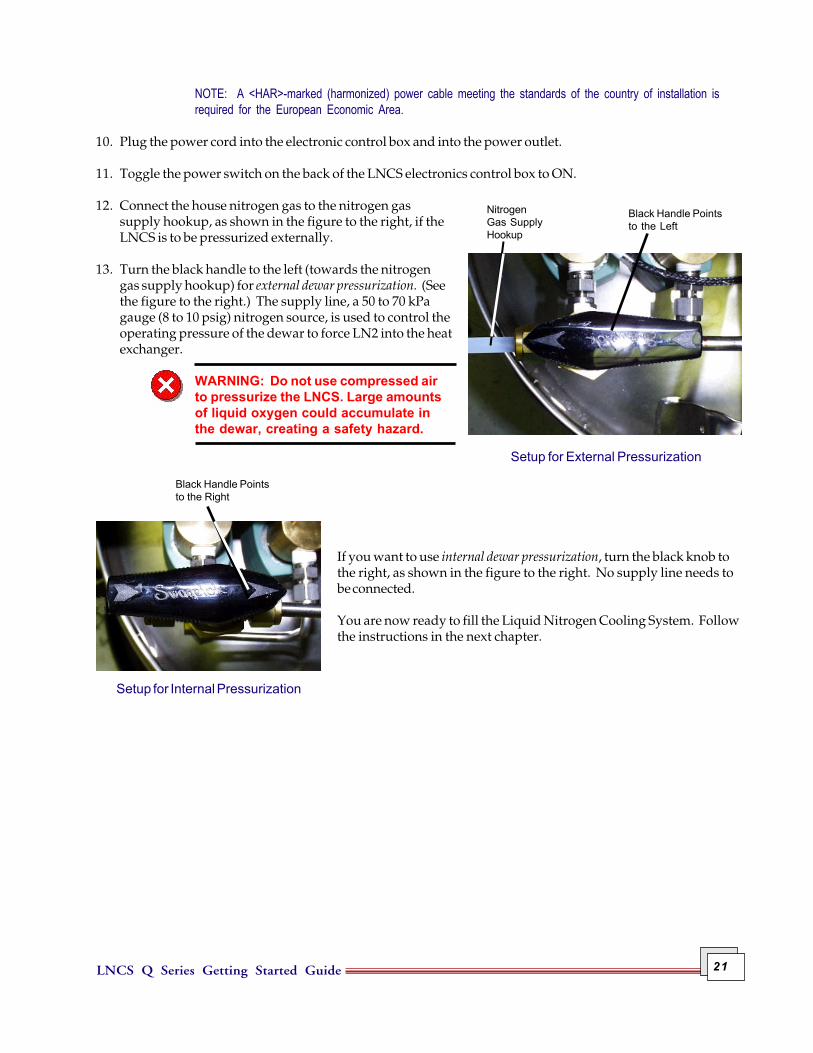
If you want to use internal dewar pressurization, turn the black knob tothe right, as shown in the figure to the right. No supply line needs tobe connected.
You are now ready to fill the Liquid Nitrogen Cooling System. Followthe instructions in the next chapter.
Black Handle Pointsto the Right
Setup for Internal Pressurization

LNCS Q Series Getting Started Guide22
LNCS Q Series Getting Started Guide 23
OverviewThe Liquid Nitrogen Cooling System (LNCS) must be filled from a bulk storage tank of liquid nitrogen. Thereare basically two methods that can be used:
• Autofilling refers to the automatic filling of the LNCS from any source, whether it is filled locally from abulk storage tank located close to the unit or filled at some remote location away from the lab. Localautofilling is the most convenient method of filling the tank. Autofill uses a function controlled from theDSC instrument control software. You can also perform an autofill sequence at a remote location, if poweris available to run the unit.
• Manual filling is the method that must be used if no power is available to allow autofilling. Manual fillingis normally done at some remote location where electricity is not accessible.
This chapter discusses the different methods used to fill the LNCS, along with information on conditioning,using, and maintaining the LNCS.
Chapter 3Filling, Conditioning, Use, & Maintenance

LNCS Q Series Getting Started Guide24
Connecting & Autofilling the LNCSTo use the local filling capability you will first need to connect the cooling accessory to a bulk source of liquidnitrogen as directed below, then fill the dewar. After the initial filling, you can set up the software to have theLNCS autofilled after experiments.
1. Arrange the low pressure bulk storage source physically close enough, within 1.8 m (6 ft), to the LNCS sothat the autofill transfer tube can be easily connected between the source and the LNCS. Likewise the LNCSand the instrument need to be in close proximity to allow connection of the 1.8-m (6-ft) transfer hose.
2. Connect the LNCS for automaticfilling as follows:
a. Attach the transfer tube to theLNCS Autofill fitting (shownin the figure to the right).
b. Attach the other end of thetransfer tube to the bulkstorage container using theunion and adapter fitting(provided in the accessory kit).
3. Install the cooling head on the DSCas directed in Chapter 2, if it is notalready installed. The cooling headmust be in place on the cell and thecell must be operational beforefilling the LNCS.
4. Turn on the power to the LNCS and the instrument.
5. Fill the dewar with liquid nitrogen before beginning an experiment following the directions in the nextsection for "Initial Autofilling."
Initial AutofillingThe LNCS must be filled before cooling experiments can be performed on DSC Q SeriesTM instruments. Followthe instructions in this section to fill the LNCS.
Using the Thermal Advantage Q Series Explorer, connect to the desired instrument. Select Control/LNCS/Fillfrom the instrument control main menu. The LNCS will be filled automatically.
The autofill will shut off when the dewar is full, the bulk storage tank is empty, or the LNCS tank pressure isbelow 1 psig for more than 1 minute. Once the dewar has been filled initially, you can set up programmedautofilling as directed in the next section.
Autofill Fitting

LNCS Q Series Getting Started Guide 25
Programmed Autofilling“Autofilling” also refers to the automatic refilling of the LNCS from the bulk storage tank between runs. Thissection tells you how to set up the LNCS and the connected instrument to allow autofilling.
The Q Series instruments automatically control the LNCS, which regulates pressure, supplying liquid nitrogento the cooling head.
To automatically refill the LNCS with liquid nitrogen after an experiment on a Q Series instrument is completed,access the Tools/Instrument Preferences/DSC Page, select LNCS Autofill if below, then enter the desiredpercent.
NOTE: The LNCS is normally filled from a bulk tank located near the unit. If you need to fill your LNCS dewarwith liquid nitrogen from a remote source (i.e., source not located near your unit), follow the directions begin-ning on the next page.

LNCS Q Series Getting Started Guide26
Remote Filling of the LNCSThere is also the ability to perform an autofill sequence at a remote location (away from the controller andinstrument), if power is available to run the unit. Depressing the Fill button on the side of the electronics controlenclosure for 3 seconds or longer initiates an autofill. This same button will reset the LNCS if depressed for lessthan three seconds.
If power is not available at the remote filling location, the LNCS can be filled manually.
This section describes both the automatic and manual remote filling methods.
Remote AutofillFollow the directions in this section to fill the LNCS automatically at a remote location:
1. Turn off the power to the LNCS.
2. Loosen the captive screws on either side of the top cover for the liquiddelivery tower. Pull the cover straight up to remove it as shown in thefigure to the right.
3. Using a 9/16-inch wrench remove the smaller liquid delivery line from itsfitting as shown in the figure below.
4. Using an 11/16-inch wrench remove the larger exhaustreturn line from the remaining fitting as shown in thefigure immediately above.
5. Pull the feed hose off the liquid delivery tower. Locatedin the top of the tower is the cap for the liquid deliveryline (shown in the figure above left). Remove the capwith its attached wire from the tower insulation.
6. Screw the cap onto the liquid delivery line. See thefigure to the right.
LiquidDeliveryLine
Exhaust ReturnLine
Cap for LiquidDelivery Line

LNCS Q Series Getting Started Guide 27
WARNING: If the feed hose is disconnected from the LNCS, the fitting on the liquidsupply line must be capped (see steps 5 and 6) to prevent liquid nitrogen from spray-ing out of the fitting during the fill process.
7. Disconnect the house nitrogen gas supply tube, if connected.
8. Disconnect the 15-pin D connector cable at the LNCS. Disconnect the 8-pin DIN cooling head connectorfrom the electronic control box.
9. Unplug the power cord, but leave it attached to the LNCS.
10. Roll the LNCS to the location of the bulk storage source and plug the power cord into the closest poweroutlet. Turn the power switch ON.
11. Make sure that the bulk storage source that will be used for filling the LNCS is a low pressure (maximum 25psi) container.
12. Connect the transfer hose from the bulk source to the autofillfitting shown in the figure here.
13. Open the valve on the bulk storage source.
14. Depress and hold the Fill button(shown in the figure to the left) on the LNCScontrol box for 3 seconds to initiate theautofill. The filling will stop automaticallywhen the dewar is full.
NOTE: Cold gas will escape from the LNCS ventduring the filling process. The fill process normallytakes 15 to 40 minutes depending on the liquid level.
NOTE: Frost will build up on the tubing and parts ofthe LNCS and storage tank while the liquid nitrogen is being transferred.
15. After the autofill has completed, allow sufficient time for any liquid remaining in the transfer tube tovaporize.
16. Close the valve on the nitrogen bulk storage tank and immediately disconnect the transfer tube from thebulk source.
17. Disconnect the transfer hose from the LNCS autofill valve, turn off the power switch, and unplug the powercord.
18. Return the LNCS to its location near the analysis instrument, and reconnect the cooling accessory byreversing steps 1 to 9.
AutofillFitting
Fill Button

LNCS Q Series Getting Started Guide28
Remote Manual FillFollow the directions in this section to fill the LNCS manually at a remote location:
1. Turn off the power to the LNCS.
2. Loosen the captive screws on either side of the top cover for the liquiddelivery tower. Pull the cover straight up to remove it as shown in thefigure to the right.
3. Using a 9/16-inch wrench remove the smaller liquid delivery line from itsfitting as shown in the figure below.
4. Using an 11/16-inch wrench remove the larger exhaust return line from the remaining fitting as shown inthe figure immediately above.
5. Pull the feed hose off the liquid delivery tower.
6. Locate the cap for the liquid delivery line (shown inthe figure above left) in the top of the tower. Removethe cap with its attached wire from the tower insula-tion.
7. Screw the cap onto the liquid delivery line. See thefigure to the right.
WARNING: If the feed hose is discon-nected from the LNCS, the fitting onthe liquid supply line must be capped(see steps 5, 6 and 7) to prevent liquidnitrogen from spraying out of thefitting during the fill process.
8. Disconnect the house nitrogen gas supply tube, if connected.
9. Disconnect the 15-pin D connector cable at the LNCS. Disconnect the 8-pin DIN cooling head connectorfrom the electronic control box.
LiquidDeliveryLine
Exhaust ReturnLine
Cap for LiquidDelivery Line

LNCS Q Series Getting Started Guide 29
10. Unplug and disconnect the power cord from theLNCS.
11. Roll the LNCS to the location of the bulk storagesource.
12. Make sure that the bulk storage source that will beused for filling the LNCS is a low pressure (maxi-mum 25 psi) container.
13. Using a 11/16-inch wrench, remove the cap from themanual fill fitting (shown in the figure to the right).Connect the transfer hose from the bulk source to themanual fill fitting.
14. Place the dewar on a scale, if one is available, so thatyou can monitor the weight to determine when thedewar is full.
15. Open the valve on the bulk storage source and leaveit open until the dewar reaches a filled weight of 87 kg (193 lbs).
WARNING: If liquid begins to spill from the vent during filling, stop the filling processimmediately by closing the valve on the bulk source. This must be done quickly toprevent freeze damage to the unit.
NOTE: Cold gas will escape from the LNCS vent during the filling process. The fill process normally takes 15to 40 minutes depending on the liquid level.
NOTE: Frost will build up on the tubing and parts of the LNCS and storage tank while the liquid nitrogen isbeing transferred.
16. Close the valve on the nitrogen bulk storage tank.
17. Allow sufficient time for any liquid remaining in the transfer tube to vaporize.
18. Disconnect transfer hose from the manual fill valve and replace the cap using the wrench to tighten snugly(do not over tighten).
19. Return the LNCS to its location near the analysis instrument, and reconnect the cooling accessory byreversing steps 1 to 10.
Manual FillCapped Fitting

LNCS Q Series Getting Started Guide30
Starting the LNCSOnce the LNCS has been properly installed, follow the steps below to set up the instrument parameters andcondition the LNCS-DSC system for optimum performance.
1. Verify the correct cooler type (e.g., LNCS) on the Tools/Instrument Preferences/DSC Page of the DSCinstrument control software.
2. Verify that a source of dry nitrogen is connected to the base purge and cooling gas (LNCS) purge. Select thegas to be used with the Gas 1 port on the back of the DSC instrument (see NOTE below).
NOTE: Dry nitrogen is used for the base purge and LNCS purge. But, if the starting temperature is belowambient, helium should be used for Gas 1 (cell purge). If the starting temperature is above ambient, nitrogenmay be used.
3. Dry the LNCS system before turning on the LNCS by following Step 1 of the conditioning procedure foundin the next section, "Conditioning the LNCS."
4. Verify that the post-test conditions (accessed through the Procedure Page by clicking the Post Test button)are set as desired. A temperature window above ambient should be used to prevent the cell from coolingdown between experiments (e.g., typical values are 35 to 50°C). Once these conditions are verified, select Goto Standby Temp from the Control menu to invoke the standby temperature set on the Tools/InstrumentPreferences/DSC Page.
NOTE: The DSC cell should be covered when not loading samples and should not be opened below ambienttemperatures.
5. Proceed to Step 2 of the conditioning procedure found in the next section, "Conditioning the LNCS" tofurther stabilize the DSC-LNCS system after installation. This cyclic experiment allows the DSC-LNCSsystem to stabilize resulting in optimized baseline and calibration.
6. Recalibrate the DSC after conditioning the system.
NOTE: When setting up experiments, be sure to verify the post-test conditions. A temperature window aboveambient should be used to prevent the cell from cooling below ambient between experiments.

LNCS Q Series Getting Started Guide 31
Conditioning the LNCS SystemEach time the LNCS heat exchanger is installed on the DSC the following conditioning procedure should be runbefore calibration and experiments are performed. The first step of conditioning is used when the system is firstinstalled and periodically thereafter to dry the system to remove moisture in the DSC cell and heat exchangerBEFORE turning on the LNCS. The second step is used to stabilize the DSC–LNCS system by cycling the systemto optimize baseline performance.
Step 1: Drying the SystemFollow the instructions below:
1. Verify that the DSC cell is empty and cover the cell. If an AutoLid mechanism is present, verify that the lidsare seated properly. (Refer to "Aligning the AutoLid in the DSC Q Series Getting Started Guide or in theonline help for instructions to align the lid, if needed.)
2. Access the Tools/Instrument Preferences/DSC Page of the DSC instrument control software. Verify thatthe correct cooler type (LNCS) is selected, check "Leave LNCS on," and verify the desired "Standby Tempera-ture."
3. Using the DSC instrument control software, access the Experimental View Summary Page. Select the"Standard" mode, then select the "Cell/Cooler Conditioning" test template from the list. This test is per-formed with the LNCS off.
4. Click on the Procedure Page.
5. Verify the default conditions of 120 minutes at 75°C and select Apply. These conditions are suitable fortypical situations.
6. Access the Post Test Parameters window and enter a temperature range window of 35 to 50°C to return thecell to slightly above ambient. Once the LNCS is operating, it is very important that the cell is always kept ator slightly above ambient temperature before and after experiments.
7. Start the experiment.
8. Upon completion of this experiment, the base and cell purges must remain on continuously. If the purgesdo not remain on, the atmospheric moisture will contaminate the system and, depending on the timeinvolved and relative humidity, the procedure may have to be repeated.
Step 2: Stabilizing the SystemThe following cyclic experiment is performed after the first step in order to allow the DSC-LNCS system tostabilize, resulting in optimized baselines and calibration.
1. Select Control/LNCS/Cool from the menu. This will enable the LNCS and begin cooling the cell. Once theLNCS has started, the flange temperature will cool rapidly to its operating temperature.
2. Verify the instrument preferences and post-test conditions as outlined in steps 2 and 6 on the previous page.
3. Verify that the cell is emptied and cover the cell.

LNCS Q Series Getting Started Guide32
4. Observe the Signal Display pane. Verify that "Set Point Temperature" displayed is at the midpoint value ofthe Temperature Range specified on the Post Test Parameters window. This indicates that the post testtemperature control is active. If the post test temperature control is not active (i.e., the "Set Point Tempera-ture" reads 0.00°C), select Go to Standby Temp from the Control menu to invoke the standby temperatureset on the Tools/Instrument Preferences/DSC Page.
5. Create and save the following "Custom" method:
1 Data Storage On2 Equilibrate 50°C3 Isotherm 60 minutes4 Mark end of cycle5 Equilibrate 300°C6 Mark end of cycle7 Isotherm 30 minutes8 Mark end of cycle9 Equilibrate –180°C10 Mark end of cycle11 Isotherm 10 minutes12 Mark end of cycle13 Ramp 20°C/min to 300°C (continued on next page)14 Mark end of cycle15 Isotherm 10 minutes16 Repeat segment 8 for 7 times
6. Start the experiment created in step 5. The flange temperature must be below 100°C when operating anLNCS. If the run is started when the flange is above 100°C, then an error message will be posted and therun will be terminated. During normal operation the flange temperature should be less than –145°C at thestart of a run.
After conditioning the LNCS (by performing both the drying and stabilization steps), evaluate the last baselinerun in the method above for any artifacts. Calibrate the DSC before running experiments using the LNCS. Seethe DSC online help for details.

LNCS Q Series Getting Started Guide 33
Using the LNCSIt is best to start the LNCS (see page 40) before you run an experiment. This allows the LNCS to stabilize andwill prevent samples from being exposed to cryogenic temperatures prior to starting a run.
Starting an ExperimentBefore you start the experiment, ensure that the DSC is connected with the controller, the standard and basepurge gases are connected, and that you have entered all necessary information through the instrument controlsoftware.
NOTE: Once the experiment is started, operations are best performed at the computer keyboard. The DSC isvery sensitive to motion and might pick up the vibration caused by touching a key on the instrument touchscreen.
Start the experiment by selecting Start on the instrumentcontrol software or by touching the START key on theinstrument touch screen (Q100 or Q1000). When you startthe instrument, the system automatically runs the experi-ment to completion.
LNCS Starting Conditions
If you are using the Liquid Nitrogen Cooling System(LNCS), the run will start when the flange (shown here),which is part of the cell structure, has reached a tempera-ture below –160 °C and when the system has detectedadequate liquid nitrogen is present. The cell temperature isthen set to 20°C and the experimental method is started.
Guidelines When Using the LNCSOnce the LNCS is properly installed, the system conditioned and calibrated, the following guidelines should bemaintained during standard experimental operation.
• A dry, moisture-free gas source is required for the cooling gas (LNCS) purge and the base purge whenusing the LNCS, in addition to the standard cell purge gas. Dry nitrogen is recommended for this purge.These gases must remain on continuously. If they do not, the atmospheric moisture will enter andcontaminate the system.
• The LNCS Purge is automatically on whenever the cell is opened by the AutoLid to prevent moisture fromentering the system. (NOTE: This does not function when the cell lid is manually opened as it is on theDSC Q10.) It is strongly recommended that the cell lids be in place anytime that a sample is not beingactively loaded or unloaded. Turn the LNCS purge on using Control/Air Cool/On prior to removing thelids. Turn the LNCS purge off after the lids are in place.
• Important: If you are planning to run subambient experiments, use helium as the purge gas. If you areusing the LNCS for rapid cooling above ambient (i.e., isothermal crystallization), then nitrogen may beused as a purge gas.
Flange Channel for Liquid Nitrogen

LNCS Q Series Getting Started Guide34
NOTE: Please make sure that you run your experiments with the same gas that you used to calibrate thesystem. For example, if you calibrate using nitrogen, make your runs with nitrogen.
• Access the Tools/Instrument Preferences/DSC Page of the DSC instrument control software. Verify thatthe correct cooler type (LNCS) is selected and check "Leave LNCS on." Check the "LNCS Autofill if below"option, then enter a percentage to automatically fill the LNCS, if desired. This indicates that you want theLNCS to automatically fill at the end of an experiment when the level of liquid nitrogen falls below thespecified percent. The fill process, when activated, will fill to completion before advancing to the nextscheduled run. If left unchecked, you will need to manually fill the LNCS when needed. (Default =checked, 40%)
• When setting up experiments, be sure to verify the post-test conditions. The temperature window shouldbe enabled and a temperature range above ambient should be used to prevent the cell from cooling downbetween experiments.
• When setting up an Autosampler sequence, access the Instrument Preferences/Autosampler Page andselect the desired sequence-end option for the LNCS.
• Important: DO NOT open the DSC cell at below ambient temperatures to prevent frost and moisturebuildup in the cell. If this occurs, the conditioning and calibration steps may have to be repeated.
• Important: Once the DSC-LNCS system has been conditioned, it is recommended that you do NOT turn offthe LNCS between runs, if the best possible baseline performance is desired.
• Important: Operating without an effective base purge, allowing the cell to remain at the lower temperaturelimit without heater power (e.g., without post-test conditions) for extended periods of time, and/orremoving the LNCS from the cell when the flange temperature is below ambient can result in excessivemoisture in the cell and requires extended time for drying such as performing Step 1 of the conditioningprocedure found in the section, "Conditioning the LNCS."
WARNING: Do not exceed 100°C with the LNCS cooling head installed and the LNCSpower off. Serious damage to the cooling head could occur.
CAUTION: We recommend that you do not use the LNCS when running isothermalexperiments above 400°C. The life of the DSC cell heating element can be shortenedif the LNCS is used at high temperatures for extended periods.
NOTE: Once the cooling flange reaches operating temperature, it condenses any moisture present. If theinitial moisture level is too high, or if the atmosphere moisture subsequently entering the heat exchangerenclosure is not minimized, then artifacts can be observed in the heat flow signals. Typically, but not exclu-sively, the artifacts are observed between 0 and 100°C, which increase in intensity over time.

LNCS Q Series Getting Started Guide 35
Maintaining the LNCSThe primary maintenance procedures described in this section are the customer’s responsibility. Any furthermaintenance should be performed by a representative of TA Instruments or other qualified service personnel.Consult the online documentation installed with the instrument control software for further information.
WARNING: Because of the high voltages in this instrument, untrained personnel mustnot attempt to test or repair any electrical circuits.
CAUTION: Before using any cleaning or decontamination method except thoserecommended by the manufacturer, users should check with the manufacturer that theproposed method will not damage the equipment.
The Liquid Nitrogen Cooling System actually requires very little maintenance. The following items may needattention and are covered in this section:
• Cleaning• Fuse replacement• Graphite gasket replacement.
Cleaning the LNCSYou can clean the LNCS as often as you like. The unit should be cleaned with a household liquid glass cleanerand soft cloth. Wet the cloth, not the unit with the glass cleaner, and then wipe off the unit and surroundingsurfaces.
WARNING: Do not use harsh chemicals, abrasive cleansers, steel wool, or any roughmaterials to clean the unit.
Replacing the FusesYou can replace the fuses found in the power entry module locatedon the rear of the electronics control box. To check or change thesefuses follow the instructions below and refer to the figure asneeded:
1. Turn the cooling accessory off and remove the power cord.
2. Insert a small screwdriver at the edge of the power entrymodule door and pry it open.
3. Insert the screwdriver on the edge of the fuse holder to pull itout of the instrument.
4. Remove old fuses and replace the fuses only with the type and rating indicated on the instrument's rearpanel.
Fuse
Fuse Holder
Fuse
PowerEntryModule

LNCS Q Series Getting Started Guide36
Teflon® Ring Graphite Gasket
Inside the Cooling Head
Snip with scissorsto slot gasket
5. Place fuse holder back into opening and push the door shut.
6. Replace the power cord and turn the unit back on.
Replacing the Graphite GasketInside the LNCS cooling head are several items that function to provide a tight seal between the DSC cell andthe cooling accessory. If you find that the cooling performance of your unit begins to produce less than desiredresults, you may need to check the graphite gasket inside the cooling head and replace it, if needed, by followingthese instructions:
1. Turn off the power to the unit and wait until the flange tempera-ture is above ambient.
2. Remove the cooling head. See the installation instructionsbeginning on page 17, if needed.
2. Turn the cooling head upside down as shown in the figure here.
3. Inspect the graphite gasket for any tears, holes, or signs of wear.Also inspect the cooling flange on the DSC cell for any graphiteresidue. Replace the gasket, if needed, by following the nextseveral steps.
4. Using a small flat head screwdriver, pry out the white Teflon®ring that holds the graphite gasket in place. The ring is slottedto allow enough flexibility for removal.
5. Remove the damaged graphite gasket and discard it.
6. Obtain the new gasket and a pair of scissors. Carefully make a cut across the diam-eter of the gasket on one side to allow installation. (It is shipped uncut to avoiddamage during shipping.)
7. Carefully press the new gasket down into the cooling head, taking care not to dam-age the thin material. Allow the edges of the gasket to slide into the groove locatedinside the cooling head for that purpose.
8. Replace the white Teflon® ring, with the beveled side facing out, so that it snaps back into place andsecures the gasket.
9. Install the cooling head on the instrument again and turn the power on.
10. Check the AutoLid alignment and adjust, if needed. See the DSC Q Series Getting Started Guide, Chapter 3"Aligning the AutoLid" for the procedure.

LNCS Q Series Getting Started Guide 37
Replacement PartsReplacement parts for the LNCS that are available from TA Instruments. See the table below when orderingparts.
Part Number Description
970408.901 Cooling Head Assembly271282.001 Power Supply970250.901 Printed Circuit Board, Control, LNCS271562.001 Fuse, 2.5A, 250V970322.901 Autofill Valve970323.901 Autofill Vent Valve970324.901 Pressure Build Valve Assembly (L11)970325.901 Pressure Build Vent Valve Assembly (L12)970326.901 Pressure Control Valve Assembly (L13)970327.901 Pressure Control Vent Valve Assembly (l14)200121.002 345 kPa gauge(50 psig) Pressure Relief Valve, Fill Tube Protection200121.001 90 kPa gauge (13 psig) Pressure Relief Valve, Dewar Protection970374.001 Gasket, Graphite, Heat Exchanger970076.001 Centering Ring Heat Exchanger970418.901 Dewar Cap Assembly

LNCS Q Series Getting Started Guide38

LNCS Q Series Getting Started Guide 39
IndexSymbols
15-pin D connector 20
15-pin D connector cable 27, 28
8-pin DIN cooling head connector 20, 27, 28
A
autofillingdefinition of 23remote 26
autofilling LNCS 24
B
BNC connector 20
bulk storage source 27, 29
C
catch troughemptying 16installation 16
"Cell/Cooler Conditioning" test template 31
cleaningLNCS 35
condensation 9
conditioning the LNCS 31
connector cablesinstalling 20
cooling accessoriesstarting conditions 33
cooling flange 34
cooling head 13, 20, 24graphite gasket replacement 36installing 18
cryogenic materials 15

LNCS Q Series Getting Started Guide40
D
dewar tank 13
Differential Scanning Calorimeter (DSC). See also instrument
drying the system 31
DSCremoving cover 17
E
Electromagnetic Compatibility Standards 7
electronic control box 20, 27, 28
electronics control box 13, 20
exhaust return line 26, 28installing 20
experimentstarting 33
external dewar pressurization 13, 21
F
feed hose 20
fiberfrax 8
filling LNCSlocal method 24remote autofill method 26remote manual method 28remote method 26 to 29
frost 9
fusesreplacement 35
G
gas linesconnecting for base purge 19
gas source 19, 33
gasket 36
graphite gasketreplacement 36

LNCS Q Series Getting Started Guide 41
I
inspecting the LNCS 15
installation 17
instrumentcooling accessories
LNCS 11maintenance 35
internal dewar pressurization 13, 21
L
lineexhaust return
installing 20liquid delivery
installing 20
liquid delivery line 26, 28capping 26, 28installing 20
liquid delivery tower 13
Liquid Nitrogen Cooling System (LNCS) 11installing 17
attaching to DSC 17prerequistes to installation 15
LNCSautofilling 23, 25cleaning 35conditioning 31cooling head
graphite gasket replacement 36drying the system 31filling
autofilling 25first time 24
filling remotely 26 to 29autofill 26manual method 28
guidelines for use 33initial filling 24inspection 15maintenance 35operation 33replacement parts 37replacing fuses 35stabilizing the system 31starting 30unpacking 15warnings 34

LNCS Q Series Getting Started Guide42
LNCS (Liquid Nitrogen Cooling System) 11components 13description 11
location 15
M
maintenance 35replacing graphite gasket 36replacing the graphite gasket 36
manual fillremote location 28
P
parts 37
post-test conditions 31, 34
R
Regulatory Compliance 7
remote filling 26 to 29
replacement parts 37
S
Safety Standards 7
specificationsLNCS 12
stabilizing the system 31
startingexperiment 33
LNCS starting conditions 33
systemdrying 31stabilizing 31
T
Teflon® ring 36
tubingbase purge 19
U
unpacking the LNCS 15