Embed Size (px)
Citation preview

7/25/2019 Lmoa2013 Book Web Final
http://slidepdf.com/reader/full/lmoa2013-book-web-final 1/252
LMOALocomotive Maintenance Ofcers Association
Proceedings of the 75th Annual Meeting
S E P T E M B E R 3 0 – O C T O B E R 1 , 2 0 1 3
Indianapolis, IN at the Indiana Convention Center
7/25/2019 Lmoa2013 Book Web Final
http://slidepdf.com/reader/full/lmoa2013-book-web-final 2/252
WORLD WIDE LEADER IN LOCOMOTIVEFUELING & SERVICING EQUIPMENT
1375 W. SNYDER BOULEVARD • NIXA, MO 65714 USAPH: 800-641-4512 • FX: 417-725-4846
www.snyderequip.com • E Mail: [email protected]
Established and reliable since 1936
EQUIPMENT CO., INC.Locomotive Fueling & Servicing Equipment
SERVING THE RAILWAY INDUSTRY SINCE 1936
WORLD WIDE LEADER IN LOCOMOTIVEFUELING & SERVICING EQUIPMENT
EMD EXHAUST EQUIPMENTFUEL TANK ADAPTERS
FUEL SIGHT GLASS CLEANING KITSREMANUFACTURED LOCOMOTIVE AIR COMPRESSORS
REMANUFACTURED “APU”- AUXILIARY POWER UNITSOLID STICK WHEEL FLANGE LUBE SYSTEMPTC SHELVING & ANTENNA ENCLOSURES
FUELING & SERVICING EQUIPMENT
HEATED HOSE REEL CABINETS (BOOM, COLUMN, PLATFORM)
FULL LINE OF METERS, AIR ELIMINATORS & CONTROL,VALVESNEW & REQUALIFIED FUEL CRANESNEW & REQUALIFIED PUMP SKIDS
ELECTRIC DERAIL SYSTEMS (wireless available)WAYSIDE FUEL FILTERS
WATER TREATMENT SYSTEMSFULL RANGE OF NOZZLES UP TO 300 GPM
NEW AND REQUALIFIED DROP HOSESCUSTOM FABRICATION
FACILITY MAINTENANCE & METER PROVINGFUEL MANAGEMENT
LOCOMOTIVE EQUIPMENT

7/25/2019 Lmoa2013 Book Web Final
http://slidepdf.com/reader/full/lmoa2013-book-web-final 3/252
LOCOMOTIVE MAINTENANCE OFFICERS ASSOCIATION 1
2013 Advertisers Index
Amglo Kemlite . . . . . . . . . . . . . . . . . . . . . . . . . . . . 7
Amsted Rail Group . . . . . . . . . . . . . . . . . . . . . . . . . 93
A.S.T. GmbH Germany . . . . . . . . . . . . . . . . . . . . . . 19
Bach Simpson . . . . . . . . . . . . . . . . . . . . . . . . 161, 229
Clark Filter . . . . . . . . . . . . . . . . . . . . . . . . . . . . . 145Electro Motive Diesels (EMD). . . . . . . . . . . . . . . . . . . 85
Graham White . . . . . . . . . . . . . . . . . . . . . . . . . . .225
Hotstart . . . . . . . . . . . . . . . . . . . . . . . . . . . . . . . 15
Industrial Specialty Chemicals, Inc . . . . . . . . . . . . . . . . 133
LPI Lift Systems . . . . . . . . . . . . . . . . . . . . . . . . . . 41
Magnus, LLC . . . . . . . . . . . . . . . . . . . . . . . . . . . . 99
Miba Bearings, U.S. . . . . . . . . . . . . . . . . . . . . . . . . 109
Morgan AM&T . . . . . . . . . . . . . . . . . . . . . . . . . . .203
Mosebach Manufacturing . . . . . . . . . . . . . . . . . . . . .177
National Railway Equipment. . . . . . . . . . . . . . . . . . . . 71
Peaker Services . . . . . . . . . . . . . . . . Outside Back Cover
Penn Locomotive Gear . . . . . . . . . . . . . . Inside Back Cover
PowerRail Distribution . . . . . . . . . . . . . . . . . . . . . . . 61Rail Products Intl. . . . . . . . . . . . . . . . . . . . . . . . . . 67
Railroad Friction Products . . . . . . . . . . . . . . . . . . . . .121
Safety Kleen Systems, Inc. . . . . . . . . . . . . . . . . . . . . .125
Simmons Machine Tool . . . . . . . . . . . . . . . . . . . . . . 47
Snyder Equipment, Inc. . . . . . . . . . . . . . Inside Front Cover
Tame, Inc.. . . . . . . . . . . . . . . . . . . . . . . . . . . . . . 55
Trains Magazine . . . . . . . . . . . . . . . . . . . . . . . . . .237
Transportation Equipment Supply . . . . . . . . . . . . . . . . . 31
Wabtec Global Services . . . . . . . . . . . . . . . . . . . . . .195
ZTR Control Systems . . . . . . . . . . . . . . .215, 217, 219, 221

7/25/2019 Lmoa2013 Book Web Final
http://slidepdf.com/reader/full/lmoa2013-book-web-final 4/252
2 LOCOMOTIVE MAINTENANCE OFFICERS ASSOCIATION
Locomotive Maintenance Ofcers Appreciate these 2013 Supporting Advertisers
Amglo Kemlite
Amsted Rail Group
A.S.T. GmbH Germany
Bach Simpson
Clark Filter
Electro Motive Diesels (EMD)
Graham White
Hotstart
Industrial Specialty Chemicals, Inc
LPI Lift SystemsMagnus, LLC
Miba Bearings, U.S.
Morgan AM&T
Mosebach Manufacturing
National Railway Equipment
Peaker Services
Penn Locomotive Gear
PowerRail Distribution
RailProducts Intl.
Railroad Friction Products
Safety Kleen Systems, Inc.
Simmons Machine Tool
Snyder Equipment, Inc.
Tame, Inc.
Trains Magazine
Transportation Equipment Supply
Wabtec Global Services
ZTR Control Systems

7/25/2019 Lmoa2013 Book Web Final
http://slidepdf.com/reader/full/lmoa2013-book-web-final 5/252
LOCOMOTIVE MAINTENANCE OFFICERS ASSOCIATION 3
2013 TOC and Index
List of LMOA Advertisers . . . . . . . . . . . . . . . . . . . . . . 2
LMOA MVP Recipients . . . . . . . . . . . . . . . . . . . . . . . 4
State of the Union Address . . . . . . . . . . . . . . . . . . . . . 20
Acceptance Speech . . . . . . . . . . . . . . . . . . . . . . . . . 24
Shop Safety, Processes and Equipment Committee . . . . . . 28–54
Diesel Material Control Committee . . . . . . . . . . . . . . 56–72
Diesel Mechanical Maintenance Committee . . . . . . . . .73–120
Fuel, Lubricants and Environmental Committee . . . . . . 122–156
New Technologies Committee . . . . . . . . . . . . . . . . 158–211
Diesel Electrical Maintenance Committee. . . . . . . . . . 212–242
LMOA By-Laws . . . . . . . . . . . . . . . . . . . . . . . 243-246

7/25/2019 Lmoa2013 Book Web Final
http://slidepdf.com/reader/full/lmoa2013-book-web-final 6/252
4 LOCOMOTIVE MAINTENANCE OFFICERS ASSOCIATION
2012 LMOA MVP RECIPIENTS
The executive board of LMOA wishes to congratulate the following
individuals who were selected as the Most Valuable People of their respective com-
mittees in 2012.
NAME COMMITTEE
Jeff Clapper, Wheeling & Lake Erie RR New Technologies Committee
Mike Drylie, CSX Transportation Diesel Electrical Maintenance
Committee
Tom Gallagher, Chevron/Oronite Fuel, Lubricants & Environmental
CommitteeMike Kader, Union Pacic RR Diesel Material Control Committee
Ted Stewart, Peaker Services, Inc Diesel Mechanical Maintenance
Committee
This honor is bestowed on an annual basis to those individuals who perform
meritorious service and make signicant contributions to their respective technical
committees.
LMOA EXECUTIVE COMMITTEE

7/25/2019 Lmoa2013 Book Web Final
http://slidepdf.com/reader/full/lmoa2013-book-web-final 7/252
LOCOMOTIVE MAINTENANCE OFFICERS ASSOCIATION 5
TheLMOA Executive Board would like toexpress their sincere appreciation to CSX
Transportation for hosting the annual
LMOA Joint Technical Committee Meeting
in Huntington, West Virginia on
May 6 and 7, 2013.
Special thanks to LMOA Regional Executive
Mike Drylie for getting CSX approval to host
the meeting and for arranging the tour ofHuntington shops and to 1st Vice President
Dave Rutkowski for coordinating the
meeting details.
Thanks to Paul Foster and Bob Harvilla
of PowerRail Distribution for hosting the
luncheon on Monday, May 6th.
We also wish to thank Magnetech and GarryFadale for allowing the LMOA committee
members to tour their facility and for
sponsoring the luncheon on Tuesday, May 7th.

7/25/2019 Lmoa2013 Book Web Final
http://slidepdf.com/reader/full/lmoa2013-book-web-final 8/252
6 LOCOMOTIVE MAINTENANCE OFFICERS ASSOCIATION
The Executive Board of the Locomotive Maintenance
Ofcers Association would like to express their deep
and sincere gratitude to Dwight Beebe of TempleEngineering for sponsoring an Executive Committee
meeting luncheon at the Chicago Sheraton Hotel
and Towers on Tuesday, September 25, 2012.
Thanks Dwight for your long and continued support
of the LMOA .

7/25/2019 Lmoa2013 Book Web Final
http://slidepdf.com/reader/full/lmoa2013-book-web-final 9/252
Amglo Kemlite Labs. Inc.
8787 Enterprise Blvd.Largo, Fl 33773
Ph: (727) 812-2000
Fax: (727) 812-2001e-mail: [email protected]
_ i _ i

7/25/2019 Lmoa2013 Book Web Final
http://slidepdf.com/reader/full/lmoa2013-book-web-final 10/252
8 LOCOMOTIVE MAINTENANCE OFFICERS ASSOCIATION
PAST PRESIDENTS
1939 & 1949 F.B. DOWLEY (Deceased) Shop Supt., C. & O. Ry.1941 J.C. MILLER (Deceased) MM, N.Y.C. & St. L.R.R.
1942-1946, Inc. J.E. GOODWINN (Deceased) Exec. Vice President, C. & N.W. Ry.
1947 S.O. RENTSCHILLER (Deceased) Chief Mechanical Ofcer, Bessemer and Lake
Erie R.R.
1948 C.D. ALLEN (Deceased) Asst. C.M.O. - Locomotive, C. & O. Ry. &
B. & O. R.R.1949 J. W. HAWTHORNE (Deceased) Vice-Pres.- Equipment, Seabord Coast
Line R.R.
1950 G.E. BENNET (Deceased) Vice-Pres.- Gen, Purchasing Agent, C. & E. I. Ry.
1951 P.H. VERD (Deceased) Vice-Pres.- Personnel, E. J. & E. Ry.1952 H.H. MAGILL (Deceased) Master Mechanic, C. & N. W. Ry.
1953 S.M. HOUSTON (Deceased) Gen. Supt. Mech. Dept. Southern Pacic Co.1954 & 1955 F.D. SINEATH, Retired Chief of Motive Power, Seabord Coast Line R.R.
1956 T.T. BLICKLE (Deceased) General Manager-Mechanical, A.T. & S.F. Ry.
1957 J.T. DAILEY (Deceased) Asst. to Pres.-Mech., Alton & Southern R.R.1958 F.E. MOLLOR (Deceased) Supt. Motive Power, Southen Pacic Co.
1958 F.R. DENNY (Deceased) Mechanical Supt., New Orleans Union Passenger Terminal
1959 E.V. MYERS (Deceased) Supt. Mechanical Dept., St. Louis-Southwestern Ry.1960 W.E. LEHR (Deceased) Chief Mechanical Ofcer, Pennsylvania R.R.
1961 O.L. HOPE (Deceased) Asst. Chief Mechanical Ofcer, Missouri Pacic R.R.
1962 R.E. HARRISON (Deceased) Manager-Maintenance Planning & Control, Southern
Pacic Co.
1963 C.A. LOVE (Deceased) Chief Mechanical Ofcer, Louisville & Nashville R.R.
1964 H.N. CHASTAIN (Deceased) General Manager-Mechanical, A.T. & S.F. Ry.1965 J.J. EKIN, JR. (Deceased) Supt. Marine & Pier Maintenance, B. & O. R.R.
1966 F.A. UPTON II (Deceased) Asst. Vice-President-Mechanical, C.M. St. P. & P. R.R.
1967 G.M. Beischer, Retired Chief Mechanical Ofcer, National Railroad Passenger Corp.
Washington, D.C. 20024
1968 G.F. BACHMAN (Deceased) Chief Mechanical Ofcer, Elgin Joliet & Eastern Ry.
1968 T.W. BELLHOUSE (Deceased) Supt. Mechanical Dept., S. P. Co., - St. L.
S.W. Ry.1970 G.R. WEAVER (Deceased) Director Equipment Engineering, Penn Central Co.
1971 G.W. NEIMEYER (Deceased) Mechanical Superintendent, Texas & Pacic Railway1972 K.Y. PRUCHNICKI (Deceased) General Supervisor Locomotive Maintenance, Southern
Pacic Transportation Company
1973 W.F. DADD (Deceased) Chief Mechanical Ofcer, Chessie System1974 C.P. STENDAHL, Retired General Manager, M.P.-Electrical, Burlinton Northern Rail-
road
1975 L.H. BOOTH (Deceased) Retired Assistant C.M.O.-Locomotive, Chessie System1976 J.D. SCHROEDER, Retired Assistant C.M.O.-Locomotive, Burlinton Northern Railroad,
244 Carrie Drive, Grass Valley, CA 959421977 T.A. TENNYSON (Deceased) Asst, Manager Engineering-Technical, Southern Pacic
Transportation Co.
1978 E.E. DENT (Deceased) Superintendent Motive Power, Missouri Pacic Railroad
1979 E.T. HARLEY, Retired Senior Vice President Equipment, Trailer Train Company, 289
Belmont Road, King of Prussia, PA 19406
1980 J.H.LONG (Deceased) Manager-Locomotive Department, Chessie Systems
1981 R.G.CLEVENGER, Retired, General Electrical Foreman, Atchison, Topeka &
Santa Fe Rwy

7/25/2019 Lmoa2013 Book Web Final
http://slidepdf.com/reader/full/lmoa2013-book-web-final 11/252
LOCOMOTIVE MAINTENANCE OFFICERS ASSOCIATION 9
1982 N.A. BUSKEY (Deceased), Asst. General manager-Locomotive, Chessie Systems1983 F.D. BRUNER (Deceased), Asst. Chief Mechanical Ofcer, R&D, Union Pacic RR
1984 R.R.HOLMES, Retired Director Chemical Labs & Environment, 600 Brookestone Mead-ows Place, Omaha, NE 68022
1985 D.M.WALKER, Retired, Asst. Shop Manager, Norfolk Southern Corp, 793 Windsor St,
Atlanta, GA 30315
1986 D.H.PROPP, Retired, Burlington Northern RR, 10501 W. 153rd St, Overland Park, KS
66221
1987 D.L.WARD (Deceased), Coordinated-Quality Safety & Tech Trng, Burlington Northern
RR1988 D.G. GOEHRING, Retired, Supt. Locomotive Maintenance, National RR Passenger
Corp, 1408 Monroe, Lewisburg, PA 17837
1989 W.A.BROWN, Retired, I&M Rail Link, 9047 NE 109th St. Kansas City, MO 64157
1990 P.F.HOERATH, Retired, Sr. Mech. Engr. Shop, Conrail 1534 Frankstown Rd, Hollidays-burg, PA 16648
1991 D.D.HUDGENS, Retired, Sr Mgr R&D, Union Pacic, 16711 Pine St., Omaha, NE
68130
1992 K.A.KELLER, Retired, Supt. Locomotive Maint, Reading RR, 241 E. Chestnut, Cleona,
PA 170421993 W.R.DOYLE, Project Manager, Sound Transit, Seattle, WA 98104
1994 M.A.COLES, Sr. Mgr-Loco. Engineering & Quality, Union Pacic RR, Omaha, NE
681791995 C.A.MILLER, Retired Mgr-Loco. Engineering & Quality, Union Pacic RR, 17745
Doras Circle, Omaha, NE 681301996 G.J.BRUNO, Retired, Supt.-Mechanical, Amtrak 14142 S.E. 154th Pl, Renton, WA1997 D.M.WETMORE, Retired-Genl Supt.-Fuel Opns, NJT Rail Opns, 2005 Acadia Greens
Drive, Sun City Center, FL 33573
1998 H.H.PENNELL, Retired-Ellcon National, 1016 Williamsburg, Lanne, Keller, TX 762481999 JAKE VASQUEZ, Retired, Asst. Supt.-Terminal Services, Amtrak 1130 Walnut Ave,
Osawatomie, KS 66067
2000 RON LODOWSKI, Retired Production Mgr, CSX Transportation, Selkirk, NY 121582001 LOU CALA, Retired, Duncansville, PA 16635
2002 BOB RUNYON, Engineering Consultant, Roanoke, VA 24019
2003 BRIAN HATHAWAY, Consultant, Port Orange, FL 321292004 BILL LECHNER, Retired, Sr Genl Foreman-Insourcing-Air Brakes, Governors & Injec-
tors, Norfolk Southern Corp, Altoona, PA 16601
2005 TAD VOLKMANN, Director-Mech. Engrg., Union Pacic RR, Omaha, NE 681792006 BRUCE KEHE, CMO, CSS&SB, Michigan City, IN 46360
2007 LES WHITE, Applications Specialist, Bach-Simpson, London, Ontario N6A 4L6
2008 MIKE SCARINGE, Director-Locomotives, Amtrak, Beech Grove, IN 461092009 DENNIS NOTT, Northwestern Consulting, Boise, ID 83703
2010 BOB REYNOLDS, Sales Manager, Amglo Kemlite Laboratories, Calgary, Alberta T24 2V8
2011 JACK KUHNS, V.P. Sales, Graham White, Salem, VA 241532012 RON BARTELS, Sr. Manager - Equipment Reliability and Electrical Engineering,
Via Rail-Canada, Montreal, Quebec

7/25/2019 Lmoa2013 Book Web Final
http://slidepdf.com/reader/full/lmoa2013-book-web-final 12/252
10 LOCOMOTIVE MAINTENANCE OFFICERS ASSOCIATION
Our Ofcers
President
R. BRAD QUEENManager of Locomotive
Utilization - RCO
BNSF Railway
Fort Worth, TX
1st Vice President
DAVE RUTKOWSKIChief Mechanical Ofcer
Providence & Worcester RR
Worcester, MA
3rd Vice President STUART OLSONRegional Sales Manager
Wabtec Corporation
Alpharetta, GA
2nd Vice President MR. BOB HARVILLAAsst. VP - Regional Sales
PowerRail Distribution
Duryea, PA

7/25/2019 Lmoa2013 Book Web Final
http://slidepdf.com/reader/full/lmoa2013-book-web-final 13/252
LOCOMOTIVE MAINTENANCE OFFICERS ASSOCIATION 11
Our Past Presidents
Chairman of Nominating Committee
RON BARTELSSr. Manager - Equipment Reliability
and Electrical Engineering
Via Rail-Canada
Montreal, Quebec
MR. BRUCE KEHEChief Mech. Ofcer
Chgo, South Shore & South Bend RR
Michigan City, IN 46360
MR. WEYLIN R. DOYLE
Project Manager
Sound TransitSeattle, WA 98104
MR. DENNIS NOTT
Sole Member
Northwestern Consulting, LLC
Boise, ID 83703

7/25/2019 Lmoa2013 Book Web Final
http://slidepdf.com/reader/full/lmoa2013-book-web-final 14/252
12 LOCOMOTIVE MAINTENANCE OFFICERS ASSOCIATION
Our Past Presidents
MR. JACK KUHNSV.P. Sales
Graham White Manufacturing
Salem, VA 24153
MR. ROBERT RUNYONRetired
Norfolk Southern Corp.
Engineering Consultant
Roanoke, VA 24042
MR. BOB REYNOLDSSales Manager
Amglo Kemlite Laboratories
Calgary, Alberta T2Y 2V8
MR. MIKE SCARINGEDirector -Locomotives
Amtrak
Beech Grove, IN 46107

7/25/2019 Lmoa2013 Book Web Final
http://slidepdf.com/reader/full/lmoa2013-book-web-final 15/252
LOCOMOTIVE MAINTENANCE OFFICERS ASSOCIATION 13
Our Past Presidents
MR. TAD VOLKMANNDirector -Mechanical Engineering
Union Pacic Railroad
Omaha, NE 68179
MR. LES WHITEApplication Specialist
Bach Simpson
London, Ontario
N6A 4L6

7/25/2019 Lmoa2013 Book Web Final
http://slidepdf.com/reader/full/lmoa2013-book-web-final 16/252
14 LOCOMOTIVE MAINTENANCE OFFICERS ASSOCIATION
Our Regional Executives
TOM PYZIAKSenior Account Executive
Safety-Kleen Systems
Palatine, IL
JEFF CUTRIGHTAssistant Manager
Norfolk Southern Corp
Roanoke, VA
JIM CHRISTOFFNational Acct. Mgr.- Traction Sales
Morgan Advanced Materials/National
Cicero, NY
RON SULEWSKISales & Marketing Manager
Business Development
Rail Products International Inc
St. Louis, MO
MIKE DRYLIEDirector-Electrical Systems
CSX Transportation
Jacksonville, FL
7/25/2019 Lmoa2013 Book Web Final
http://slidepdf.com/reader/full/lmoa2013-book-web-final 17/252
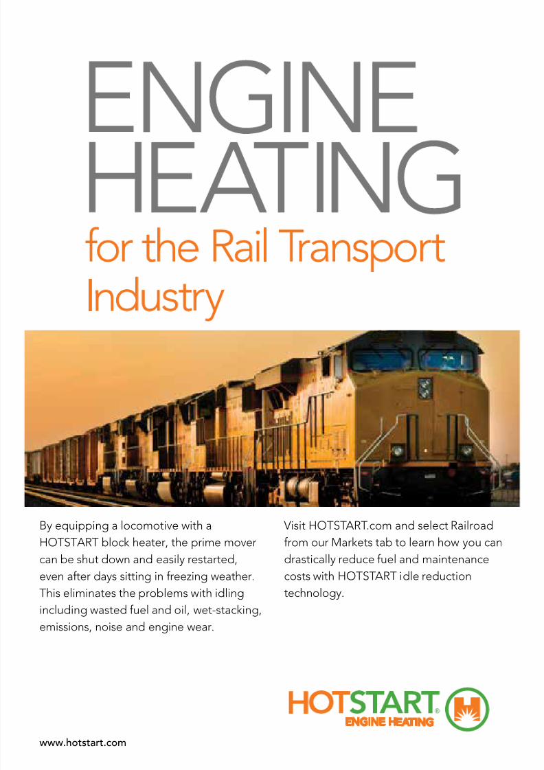
By equipping a locomotive with a
HOTSTART block heater, the prime mover
can be shut down and easily restarted,
even after days sitting in freezing weather.
This eliminates the problems with idling
including wasted fuel and oil, wet-stacking,
emissions, noise and engine wear.
Visit HOTSTART.com and select Railroad
from our Markets tab to learn how you can
drastically reduce fuel and maintenance
costs with HOTSTART idle reduction
technology.
www.hotstart.com
ENGINE HEATING

7/25/2019 Lmoa2013 Book Web Final
http://slidepdf.com/reader/full/lmoa2013-book-web-final 18/252
16 LOCOMOTIVE MAINTENANCE OFFICERS ASSOCIATION
Newly elected President, Brad Queen, BNSF, accepting gavel from outgoing
President Ron Bartels, Via Rail which was witnessed by Past PresidentBob Reynolds, Amglo Kemlite.
Past Presidents Bob Runyon (left) and Tad Volkmann, Union Pacic, presenting
outgoing President Ron Bartels with LMOA watch.

7/25/2019 Lmoa2013 Book Web Final
http://slidepdf.com/reader/full/lmoa2013-book-web-final 19/252
LOCOMOTIVE MAINTENANCE OFFICERS ASSOCIATION 17
Past President Les White, Wabtec/Bach Simpson, is about to present outgoing
President Ron Bartels with the Past President’s Pin. Ceremony was witnessed bynewly elected President Brad Queen and Past President Jack Kuhns,
Graham White Mfg.
Past President Bob Reynolds assists newly elected 3rd VP Stuart Olson, Wabtec,
with his LMOA Blazer. Past President Dennis Nott, Northwestern Consulting,
(left), newly elected President Brad Queen and Past President Bruce Kehe,
Chicago South Shore and South Bend RR, attended the ceremony.
7/25/2019 Lmoa2013 Book Web Final
http://slidepdf.com/reader/full/lmoa2013-book-web-final 20/252
18 LOCOMOTIVE MAINTENANCE OFFICERS ASSOCIATION
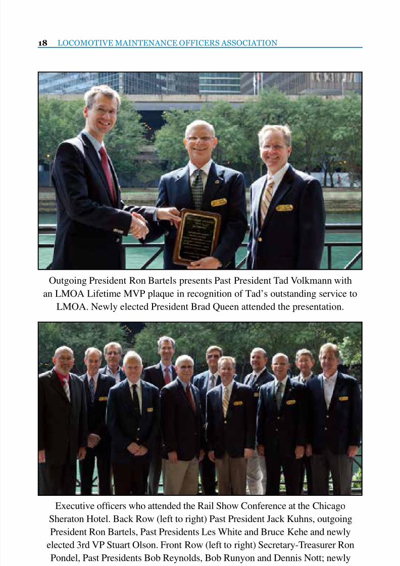
Outgoing President Ron Bartels presents Past President Tad Volkmann with
an LMOA Lifetime MVP plaque in recognition of Tad’s outstanding service toLMOA. Newly elected President Brad Queen attended the presentation.
Executive ofcers who attended the Rail Show Conference at the Chicago
Sheraton Hotel. Back Row (left to right) Past President Jack Kuhns, outgoing
President Ron Bartels, Past Presidents Les White and Bruce Kehe and newly
elected 3rd VP Stuart Olson. Front Row (left to right) Secretary-Treasurer Ron
Pondel, Past Presidents Bob Reynolds, Bob Runyon and Dennis Nott; newly
elected President Brad Queen, Past President Tad Volkmann and newly elected
2nd VP Bob Harvilla, PowerRail Distribution.

7/25/2019 Lmoa2013 Book Web Final
http://slidepdf.com/reader/full/lmoa2013-book-web-final 21/252
Over 4,000 Idling Stop Systems world-wide
=> save energy
=> reduce emission
=> smart & silent
=> maintenance free
=> never idle
Self-powered through
Thermo Electric Generator (TEG)
Idling Stop Technology ...
Stop Global warming ... Save Money

7/25/2019 Lmoa2013 Book Web Final
http://slidepdf.com/reader/full/lmoa2013-book-web-final 22/252
20 LOCOMOTIVE MAINTENANCE OFFICERS ASSOCIATION
Good afternoon, ladies and
gentlemen. Welcome to the 2012
session of the LMOA technical
presentations and I want to thank youall for attending.
For the next few minutes I’ll give
you a snapshot of the year 2012 from
an LMOA standpoint.
In the second week of May, we
held our annual Joint Committees
meeting in Overland Park, Kansas,
at BNSF’s training center. We hada good turnout of about 60 people,
and we got a chance to preview and
critique some of the presentations you
have heard this morning or are about
to hear this afternoon and tomorrow
morning. Brad Queen, our rst VP
and also from BNSF, did a fabulous
job of organizing the meeting and,
Brad, I want to thank you for that
and also your employer, BNSF, for
hosting and sponsoring the event.
After the meetings and presentations,
we were given a tour of the training
center. It is a very impressive facility
and I can’t think of a railroad trade
that isn’t taught there.
Sponsors are also an important part of this conference. It was
made possible in part by: Loram
Maintenance of Way, The Greenbrier
Companies, Norfolk Southern
Thoroughbred Mechanical Services,
GATX Corporation, New York Air
Brake Corporation, and Sterling
Rail. Specically, our LMOA audio-
visual requirements were sponsored
by Graham-White. We all havethese companies to thank for their
generosity so I think they deserve a
round of applause. Make sure you
visit their exhibits, and all of the
others, too, when you’re not attending
the presentations.
I’m going to go back to the joint
committees meeting for a minute.There was a lot of technical talk
but we also took the time to honor
one of the LMOA’s most valuable
members. If you weren’t at the
meeting, you may be wondering
“Who is this person” or “What did he
or she do”? Those are good questions.
You might be thinking that he gave
inspirational technical presentations
and wrote informative papers: No.
Maybe he chaired a committee or
two: No. He must have served as
Regional Executive, Vice President or
President of the LMOA. Guess what.
No, again. So if he hasn’t done any of
those things, why am I even talking
about him?The person I’m talking about
is Ron Pondel. Since Ron has been
Secretary-Treasurer of the LMOA,
(by the way, it has been almost 25
years, quite an accomplishment)
in one way or another he has been
2012 State of the Union Address
President, Ron Bartels
Monday Afternoon , Spetember 24, 2012

7/25/2019 Lmoa2013 Book Web Final
http://slidepdf.com/reader/full/lmoa2013-book-web-final 23/252
LOCOMOTIVE MAINTENANCE OFFICERS ASSOCIATION 21
a part of every presentation and
paper produced by the technical
committees. He has guided everychairperson, Regional Executive, VP,
and President though their LMOA
careers to make everything go as
smoothly as possible. He has done
everything in his power to make
every LMOA meeting and event a
success and he never hesitates to help
out when help is needed. I remembera few years ago at the annual
conference at the Hilton, I was setting
up with Dean Becker to demonstrate
a high intensity headlight for my
presentation and we needed the right
background to illuminate. Ron saw
what we were trying to do and in no
time he had the Hilton staff hoppingand bringing in different curtains on
moveable racks to get just the right
effect. This is just situation normal
for Ron.
The inspiration for the Ron
Pondel Lifetime Achievement
Award came from our second VP,
Dave Rutkowski. Thanks, Dave, for
that brilliant idea. The award gives
recognition to those individuals
who have provided exemplary
service to the LMOA. The Executive
Committee felt that Ron Pondel
truly exemplies the values of the
LMOA, and wanted to recognize his
service by naming this award in his
honor. The award will live on in RonPondel’s name and only those people
who show the same qualities and
devotion to LMOA as Ron will have
the honor of receiving the award.
Congratulations, Ron.
We had another rst for 2012:
This year was the rst full year of
the newly branded Shop Safety,Processes, and Equipment committee.
It used to be known as the Shop
Equipment committee but last year
the committee’s focus was expanded
to emphasize safety and include
processes in its mandate. This change
alone may not be worthy of an award
but it is noteworthy. Committeechairman Bill Peterman actively
marketed the broader mandate
of the committee last year within
the industry but did not get much
reaction. He will be continuing his
promotion of the committee at this
conference so if you or someone
you know wants to contribute tothe committee, or just nd out more
about it, please talk to Bill. Also,
make sure you are here tomorrow
morning at 10:45 when Bill and the
committee educate us about Shop
Safety, Processes, and Equipment.
Some of you may recall at last
year’s Joint committees meeting at
Union Pacic headquarters in Omaha,
John Estes of UP appealed to the
LMOA to address the unsatisfactory
reliability of locomotives, especially
when they are fresh “out of the
box”. The LMOA took this request
very seriously and this past year,
locomotive reliability has been a
major focus within the LMOA.This afternoon and tomorrow
morning, the New Technologies and
Electrical committees will give three
presentations dealing with reliability,
both building it into locomotives and
systems and improving it throughout

7/25/2019 Lmoa2013 Book Web Final
http://slidepdf.com/reader/full/lmoa2013-book-web-final 24/252
22 LOCOMOTIVE MAINTENANCE OFFICERS ASSOCIATION
the life cycle. The Mechanical
committee also has a written paper
on the subject. You can nd it inthe 2012 LMOA Proceedings. A
good number of the remaining
presentations at this conference
describe specic methods, tools, or
components that will help improve
a locomotive’s reliability. Pay close
attention to the presentations and ask
questions if you want to know more.Our members will do what they can
to help you.
If you ask me, they already
have been helping. Just look at some
encouraging reports from the North
American railroad industry. Since
the year 2002, Amtrak’s ridership
has increased by 44%. In the 2
nd
quarter of 2012, the majority of
North American Class 1 freight
railroads reported strong nancial
results and set a number of nancial
records. Many of them showed
strong revenues. At the same time,
costs, productivity, and operating
ratios were mostly favorable. The
LMOA can have a big impact on
those indicators. Our activities
help improve safety, reliability,
productivity, and maintenance costs,
and provide solutions to reduce the
railroads’ impact on the environment.
Ridership and revenues are equally
impacted by LMOA activities.
Try attracting new customers ormaintaining your customer base when
trains don’t reach their destination or
are late due to unreliable locomotives.
Judging by the number of railroad
members who registered early
for LMOA at this conference, the
railroads are realizing the value of
participation in the LMOA and that
helps ensure a strong future for theorganization.
My year in this position is just
about over and I would not have
made it here on my own. I want to
thank the three most important people
in my life, my wife, Karen, and my
two daughters, Kaitlin and Hannah
for always being there for me. I alsoowe thanks to my employer, VIA
Rail Canada, for supporting me and
believing in the LMOA. And last but
not least, I want to thank our three
VP’s, Brad Queen, Dave Rutkowski,
and Bob Harvilla, our Secretary-
Treasurer Ron Pondel, and all the
members of the LMOA for being sodedicated and always helpful.
Thank you, and enjoy the rest of
the conference.

7/25/2019 Lmoa2013 Book Web Final
http://slidepdf.com/reader/full/lmoa2013-book-web-final 25/252
LOCOMOTIVE MAINTENANCE OFFICERS ASSOCIATION 23
LMOA Executive Board Meeting on Tuesday, September 25, 2012 at the
Chicago Sheraton Hotel and Towers.

7/25/2019 Lmoa2013 Book Web Final
http://slidepdf.com/reader/full/lmoa2013-book-web-final 26/252
24 LOCOMOTIVE MAINTENANCE OFFICERS ASSOCIATION
Before I begin, I would like
to thank Ron Pondel for all his
dedication and tremendous support to
this organization.I am extremely honored to have
been selected as the next President of
the LMOA for 2012-2013. Above all,
I am grateful to all the members who
have provided excellent mentorship
and professional advice throughout
the past 12 years of membership,
which has brought me here todayaccepting the responsibilities and
your trust as President for the LMOA.
I began my railroad career in Lincoln
NE at the Burlington Northern’ s
Lincoln Diesel shop as an Electrician
Apprentice about 18 years ago
after serving in the US Navy. I got
a chance to learn how to work on
GP-9s, SW1500s, Dash 7s, and my
favorite locomotive the SD40-2.
Then, I saw the rst SD70 Mac that
came on property. I couldn’t wait to
go to that rst electrical class at our
TTC to learn how to work on one
of those! In 2000, I was promoted
to Mechanical Foreman at the
BNSF Topeka System MaintenanceTerminal or as it is more popularly
known as our “Locomotive Back
Shop”. It was that year I was asked if
I wanted to join the LMOA. Looking
back at those ve years in Topeka, I
learned to work in every department
there, got my degree at night school,
and wrote 3 papers for the LMOA’s
New Tech Committee. One other
achievement in Topeka during my
last year there was that we nalizedproduction to begin rebuilding those
SD70-Mac’s AND we had an entire
shop go injury free. Also during this
time, I would volunteer during my off
time and used LMOA to learn more
about subjects like remote control
locomotives, visiting other shops and
industries to see their best practices,and helped identify improvements to
equipment or processes.
In 2005 I went to Barstow
California as a General Foreman
and also served as Chairman of
the LMOA’s New Technologies
Committee. I hosted quite a few
LMOA committee meetings at
this major locomotive facility
which was exciting to brainstorm
improvements or Best Practice ideas
with our members on subjects such
as engine change outs, the number of
locomotives we service a day there,
and the heat! I kept working with
these remote control locomotives
there in Barstow as well. I then wenton to work as a Quality Manager
and then our Mechanical Best Way
Process Improvement Team.
At the end of 2011, I became a
member of a new Remote Control
Locomotive department at our Fort
Worth headquarters. I truly believe
Acceptance speech
Brad Queen
Tuesday Morning, September 25, 2012

7/25/2019 Lmoa2013 Book Web Final
http://slidepdf.com/reader/full/lmoa2013-book-web-final 27/252
LOCOMOTIVE MAINTENANCE OFFICERS ASSOCIATION 25
that the majority of my success has
been from the network of contacts
that I have made through the LMOAorganization and by LMOA providing
me the opportunity to share our
research of the railroad industry
to audiences such as everyone
sitting here today at these technical
proceedings.
Every time something new came
along such as Gen Sets or somethingold such as fuel tank repairs that I
needed to get a better understanding
of, I used the LMOA as a tool to do
the necessary in-depth research with
suppliers or even other Railroads
to write papers on these subjects.
The results of this knowledge or
experience have advanced me and myteams within the Railroad industry.
I would also like to tie LMOA
together to what is taking place to
our Railroad industry which is in
the midst of colossal greatness. We
are the movers! And it just isn’t
possible to keep adding more lanes
on to our current highway systems.
We also have a huge technological
change with positive train control,
live remote monitoring capabilities
of our equipment, and electronic train
inspections. In addition, we provide
the greenest possible service that is a
proven benet to the air, ground, and
noise that we need and have to take
responsibility for. We are also movingforward every day towards the safest
possible industry as a transportation
service. Everything is safety, to how
we do our work to how our suppliers
deliver or make their products we use.
We get it and we do it!
Yes, we are making history
with our innovations and we are
able to aggressively adapt like noother industry. So much so, that you
can now go to school to become a
“Railroader”. This is why LMOA is
so important as to not only provide
excellent personal development; we
are also the platform for our industry
to uncover these technologies,
services, and safety possibilities ofour railroad industry.
Highlight of this year’s papers are:
Diesel Material Control Committee
Chairman Fred Miller, Relco
Locomotive
1. Tracking Cores: Mike Kadar,
Union Pacic RR2. Bar Coding Update-Ron
Delevan-Morgan AM&T/National
Diesel Mechanical Maintenance
Committee
Chairman Ian Bradbury, Peaker
Services
1. Generator Alignment &
Changeout-Rich Aranda, Belt Rwy
and James Sherbrook, LocoDocs
2. Proper Torqueing Procedures
Update – Tim Standish, EMD
3. (Website) Finding an
EPA Certied Emissions Kit for
Locomotive Engine Overhaul-Ted
Stewart-Peaker Services.
4. Locomotive Idle Minimization
(Use of APU or AESS)-Bill Edwards,
MRL & Dave Rutkowski, Providence
& Worcester RR
(Failure Modes and Effects
Analysis paper by Tom Kennedy, UP
RR published in the LMOA book)

7/25/2019 Lmoa2013 Book Web Final
http://slidepdf.com/reader/full/lmoa2013-book-web-final 28/252
26 LOCOMOTIVE MAINTENANCE OFFICERS ASSOCIATION
Fuel, Lubricants & Environmental
CommitteeChairman Dwight Beebe, Temple Engi-
neering
1. Gen-6 Locomotive Engine Oil
Denition -- The Next Generation
Loco Engines for Heavy Haul-George
Lau, CN, Tom Gallagher, Chevron
Oronite
2. Biodiesel Background for the RR Sector-Kyle Anderson & Richard
Nelson, National Biodiesel Board
3. Incipient Engine Failure
Detection Tool-Najeeb Kuzhiyil &
Manoj Kumar, GE
4. Locomotive Durability
Test Protocol for Alternate Fuels
& Biodiesel (Suggested eld test protocol to evaluate the impact
of blended biodiesel) -Dennis
McAndrew, Dennis W. McAndrew Inc.
New Technologies Committee
Chairman Jim Christoff, Morgan
AM&T/National
1. Using the A3 Problem Solving
Solution-Tad Volkmann, Union
Pacic RR
2. Locomotive Repower with
a High-Speed Engine & Reduction
Gearbox-Bruce Wolff, MTU
3. A New EFI Tier 0+ Solution
for EMD 645 Engines-Jeff Clapper,
Wheeling & Lake Erie RR
4. Tractive Effort andAdhesion-A Study-Tom Mack,
Motive Power & Equip Solutions
Congratulations to newly
elected Chairman Tom Mack & also newly elected V-Chair & MVP Jeff
Clapper, Wheeling & Lake Erie
RR. Lastly, Tad Volkmann, Union
Pacic RR as our Life Time MVP
Achievement award.
Diesel Electrical Maintenance
CommitteeChairman Mike Drylie, CSX Transpor-
tation
1. Extending Locomotive
Maintenance to 184 days–Part II-
Mike Drylie, CSX
2. Lifecycle Reliability Analysis
of Locomotive Systems Design-Guest
Speaker Scott Werner, Wabtec MotivePower
3. Design for Reliability-
Locomotive Control Systems- Guest
Speaker Jason Fox, Union Pacic RR
4. Three Stage Battery Charging
for EMD Locomotives- Bud Wilds, BN
Shop Safety, Practices and
Equipment Committee
Chairman Bill Peterman,
Peterman Railway Technologies
1. Application of Machine Vision
in the Railroad Industry-Trackside
Systems for Measuring Condition
of Many Freight Car Undercarriage
Parts – Potential Use in Locomotive
Applications-Sam Williams, BeenaVision Systems
2. Parts Washing by Proceco
3. Train Washing with Emphasis
on Recycling Water

7/25/2019 Lmoa2013 Book Web Final
http://slidepdf.com/reader/full/lmoa2013-book-web-final 29/252
LOCOMOTIVE MAINTENANCE OFFICERS ASSOCIATION 27
If you haven’t notice, three of
these authors or presenters are from
the Union Pacic Railway. I wish tocongratulate them for their dedication
and professional railroad knowledge.
There is an overwhelming amount
of personal commitment for these
papers as well as time practicing
presentation skills which is just not
easy for a lot of people. It is one thing
to write some type of presentation tosend out for everyone to simply read
but to write a presentation and stand
up in front of a large group to present
it is not easy and takes courage. Also
congratulations to the MVP recipients
from the committees. Their managers
will get a letter recognizing their
special contributions to their respectivecommittees along with a plaque
presented to the recipient on behalf of
the executive ofcers of LMOA.
There is also a large number of
our Past Presidents who have returned
back to committee work which shows
the dedication within the ranks of
LMOA. Please thank: Les White &
Bob Reynolds – Electrical. Dennis
Nott & Jack Kuhns – Mechanical.
Bruce Kehe & Tad Volkmann – New
Technologies. Mike Scaringe – Shop
Safety Processes & Equipment. And of
course Bob Runyon who stays active
on the executive board.
I would like to now thank
President Ron Bartels, Via Rail.Ron’s dedication to this organization
has carried it on for another year of
success. I would also like to thank the
guest speaker for the opening general
session and for his support, Carl
Ice the President & COO of BNSF
Railway. Also for the BNSF Technical
Training Center in Overland Park KS
for hosting the 2012 LMOA JointCommittee meeting in May.
I wish to thank the advertisers
who make the printing of the LMOA
book nancially feasible and those
who have committed to doing this
for a long time. Thank you to the
companies who supported/sponsored
committee meetings during the year.Also a very special thanks to Graham
White who generously contributed to
RSI to help out with AV expenses for
LMOA presentation. Lastly, thanks to
the more than 100 vendors who are
displaying this year. Well done to all!
I would encourage all railway
executives, managers, shoppersonnel, and railroad suppliers
to be supportive and inspire their
companies to actively participate in
the LMOA. In closing I would like to
challenge everyone to communicate
a few of LMOA’s benets to our
professional associates.
• The ability to work with others to
achieve a common goal
• Increase in the railroad industries’
technical or educational knowledge
• Experience of speaking or presenting
in front of a knowledgeable audience
• Ability to follow through on a
deadline
• Expanded people skills
I look forward in seeing everyone
here today and more again at our
2013 Convention in Indianapolis,
Indiana September 29 - October 1.

7/25/2019 Lmoa2013 Book Web Final
http://slidepdf.com/reader/full/lmoa2013-book-web-final 30/252
28 LOCOMOTIVE MAINTENANCE OFFICERS ASSOCIATION
Report on the Committee
on Shop Safety, Processes and Equipment
Monday, September 30, 2013 at 9:30 A .M.
Chairman
Bill PetermanDirector–Rail Operations
B.P. Railway Services
Baie D’Urfe, Quebec
Vice Chairman
Tom StefanskiPresident
Tom’s Locomotive and Cars
Plaineld, IL
Commitee MembersR. Begier Consultant Broomeld, CO
C. Bentler Sr. Genl Foreman Norfolk Southern Bellevue, OH
D. Bossolono Shop Supt. BNSF Rwy Kansas City, KS
R. Collen Project Mgr. Simmons Mach. Tool Corp. Albany, NY
R. Covert Product Manager Frt. Rail Macton Corp. Oxford, CT
C. Fette President TESCO Erie, PA
M. Scaringe Dir. Locomotives Amtrak Beech Grove, IN
(Past President)

7/25/2019 Lmoa2013 Book Web Final
http://slidepdf.com/reader/full/lmoa2013-book-web-final 31/252
SHOP SAFETY, PROCESSES AND EQUIPMENT 29
P E R S O N A L H I S T O R Y
Bill Peterman
Bill was born and raised in Galt,
Ontario Canada and has worked andlived in various parts of Canada dur-
ing his railroad career including major
stints in Calgary and Montreal where
he presently resides. His business ca-
reer included 25 years with Canadian
Pacic Railway and several years
with Dominion Bridge in Canada in
numerous industrial and facilities en-gineering positions including various
positions in the maintenance facilities
and head ofce. Gained a world of rail
experience working in all aspects of
service facilities. His railway career
began as a Time and Motion Analyst
completing his time with the railway
as Manager Facilities Engineer.Currently, Bill is Director–Rail
Operations of B.P. Railway Services, a
company specializing in assisting with
Rail Maintenance designs, equipment
and processes, providing specialized
rail maintenance serves and acting as
a liaison between railway and non rail-
way entities.He has been Chairman of the
Shop Safety, Processes and Equipment
Committee for several years. Bill lives
in Montreal and is married with 5 chil-
dren and nally has 3 grandchildren.

7/25/2019 Lmoa2013 Book Web Final
http://slidepdf.com/reader/full/lmoa2013-book-web-final 32/252
30 LOCOMOTIVE MAINTENANCE OFFICERS ASSOCIATION
The Shop Safety, Processes and Equipment
Committee would like to extend their sincere
gratitude to the Canadian Pacic Railway for hostingthe committee meeting in Montreal, Quebec,
Canada in November 2012.
The committee would also like to thank the BNSF
for hosting their March 2013 meeting in San
Bernardino, California and for sponsoringa luncheon.

7/25/2019 Lmoa2013 Book Web Final
http://slidepdf.com/reader/full/lmoa2013-book-web-final 33/252
T E S C O ~
TR NSPORT TION EQULPMEICT
SUPPLY COMP IIIY
•
t tJ
Transportation Equipment Supply Company
81
6
Hawthorne Drive
Erie,
P
16509
(814) 866-1952
fax
(814) 866-7307
Contact us for all your special tooling needs
·
}
www tescotools com

7/25/2019 Lmoa2013 Book Web Final
http://slidepdf.com/reader/full/lmoa2013-book-web-final 34/252
32 LOCOMOTIVE MAINTENANCE OFFICERS ASSOCIATION
Overview
The function of a fastener such
as a bolt is to hold or clamp twosurfaces together. In order for the
bolt to properly perform this function,
the correct amount of torque needs to
be applied to the bolt with properly
lubricated and undamaged threads.
This applied torque will cause the
bolt to stretch and act as a spring to
clamp and hold the joint together.
The amount of bolt tension or
stretch is what determines a properly
fastened joint. If the bolt is not
stretched enough, the joint will be loose
and could possibly lead to failure. Too
Bolt Torquing / Tensioning
Manual Torque Wrenches and Adapters
Prepared by: John Fette, TESCO
Presented by: Chuck Bentler, Norfolk Southern
much stretch can weaken the bolt and
also possibly lead to failure.
The relationship between torqueand bolt tension can be inuenced by
several factors, these being: the type
of lubricant used on the threads, the
material from which the bolt and nut
are made, the type of washers used,
the class, nish, and condition of the
threads.
To demonstrate theserelationships, a study was performed
to show how dramatically these
factors inuence the amount of
clamping force on a joint.
Study Summary
This study was performed to
calculate the amount of bolt stretch
and clamping force that is generated
by a fastener that is properly
lubricated, has clean and undamaged
threads, and where the installation is
performed with a properly calibrated
torque wrench. This clamping
force will then be compared to the
clamping force generated by the
following installation conditions:1. Installation with an improperly cali-
brated torque wrench
2. Installation with a non-lubricated
fastener
3. Installation with damaged threads
on fastener

7/25/2019 Lmoa2013 Book Web Final
http://slidepdf.com/reader/full/lmoa2013-book-web-final 35/252
SHOP SAFETY, PROCESSES AND EQUIPMENT 33
Fasteners Used for Study:
Test Plates
Torque Wrench Used: 30-250
Ft-lb Micro-Adjustable Wrench with
1/2” square drive
Lubricant Used:
Molycote GN Metal Assembly Paste
Test #1 – Calibrated Torque
Wrench/Clean and Lubricated
ThreadsOur Test #1 was set up to show
how a properly assembled and
torqued joint would behave. Thread
gauges were used to check both the
male threads on the bolt as well as
the female threaded holes in the test
plate. We veried the set points of
the torque wrench using an electronictorque tester with an accuracy of
+/- .5% The bolts had their bottom
surfaces ground at, perpendicular to
the bolt’s axis. The bolt threads were
properly lubricated and then used
to attach the test plates together as
shown.
The bolts were torqued to an
initial torque of 10 Ft-lbs. At this
point, the depth D was measured
to provide a base point for the bolt
length. The bolts were each then
torqued to a nal torque value
of 65 Ft-lbs. The depth D was
again measured for each bolt. The
difference between the initial D andnal D gave us the amount of bolt
stretch. The results were as follows:
Initial D Final D StretchBolt 1 .238" .233" .005"Bolt 2 .241" .236" .005"

7/25/2019 Lmoa2013 Book Web Final
http://slidepdf.com/reader/full/lmoa2013-book-web-final 36/252
34 LOCOMOTIVE MAINTENANCE OFFICERS ASSOCIATION
Using the following equation for
the bolt stretch, we can calculate the
clamping force for each bolt:
Stretch (S) = FL
AE
F = clamping force
L = initial bolt length (1.725”)
A = cross sectional area of bolt
(.1142 square inches)E = Modulus of Elasticity
(30000000 psi)
Using the stretch value of .005”,
we can calculate for the clamping
force F.
F = SAE L
F = (.005”)(.1142 square inches)(30000000 psi)
1.725”
F = 9930 pounds per bolt
With the clamping force now
calculated based on the bolt stretch, we
installed the test plate assembly into a
hydraulic testing rack as shown below.
The test rack was designed
so that it would attach to and
hydraulically pull the plates apart.The purpose behind the test was to
incrementally increase the amount
of force used to pull on the plates
up to the point where separation
occurs between the plates. This
would indicate the point at which the
clamping force has been overcome
and provides us with a way to verifywhat that clamping force actually is.
The test rack is equipped with a
single acting hydraulic ram with an
effective area of 11.05 square inches.
The hydraulic pressure is indicated
on a 10,000 psi gage which has been
calibrated using a Fluke P-3116-3
Dead Weight Tester which has anaccuracy of .015% of the reading.
The results for the pull test on
our Test #1 assembly are as follows:
Force
Applied (lbs)
Separation
at Bolt #1
Separation
at Bolt #2
13260 None None
14365 None None
15470 None None
16575 None None
17680 None None
18785 None None
19890 .001” .001”
With separation occurringevenly at 19890 pounds, it translates
into 9945 pounds of clamping force
per bolt. This is within .2% of our
calculated value based on the bolt
stretch.

7/25/2019 Lmoa2013 Book Web Final
http://slidepdf.com/reader/full/lmoa2013-book-web-final 37/252
SHOP SAFETY, PROCESSES AND EQUIPMENT 35
Test #1 Summary
The purpose of this rst test
was to provide us with a baseline tocompare to in subsequent tests. We
have shown that by using a properly
calibrated torque wrench along with
clean and lubricated threads, this
fastener when torqued down to a
value of 65 Ft-lbs will provide 9945
pounds of clamping force.
In this test, the theory has beenvalidated in practice.
The following tests will show
the impact that such things as torque
wrench calibration, lubrication and
thread condition can have on the
clamping force.
Test #2 – Out of CalibrationWrench/Clean and Lubricated
Threads
In this test, the condition of
the threads and lubrication were
the same as in Test #1. The only
difference was that the set point of
the wrench was dropped to 50 Ft-lbs.
This was intended to simulate what
could happen if a wrench is out of
calibration. The bolts were torqued
down and the test plate assembly was
placed into the hydraulic testing rack.
The results were as follows:
Force
Applied (lbs)
Separation
at Bolt #1
Separation
at Bolt #2
8840 None None9945 None None
11050 None None
12155 None None
13260 None None
14365 None None
14917 .001” .001”
This shows us that a clamping
force of only 7459 per bolt is
generated versus the expected valueof 9945.
In this test, theory is not
supported by the practice.
Test #3 – Calibrated Wrench / Clean
and Non-Lubricated Threads
In this test, a calibrated torque
wrench was used, set and veried at65 Ft-lbs. The threads on both the
fastener and hole were clean, but no
lubrication was used. The results of
this test were as follows:
ForceApplied (lbs)
Separationat Bolt #1
Separationat Bolt #2
5525 None None
6630 None None
7735 None None
8840 None None
9945 None None
11050 .001” .002”
The uneven amount of separation
shows that the clamp forces generated
by the bolts were not equal. Theaverage force per bolt was 5525
pounds, well below our value of 9945
in Test #1. What this shows us is that
with the bolts not being lubricated,
a greater amount of the input torque
is absorbed by the system friction,
causing less to be applied to bolt
stretch and clamping force.In this test, theory is not
supported by the practice.

7/25/2019 Lmoa2013 Book Web Final
http://slidepdf.com/reader/full/lmoa2013-book-web-final 38/252
36 LOCOMOTIVE MAINTENANCE OFFICERS ASSOCIATION
Test #4 – Calibrated Wrench/
Damaged and Non-Lubricated
ThreadsIn this test, a calibrated torque
wrench was used, set and veried
at 65 Ft-lbs. The threads on both
the fastener were damaged, and no
lubrication was used. The results of
this test were as follows:
ForceApplied (lbs)
Separationat Bolt #1
Separationat Bolt #2
3315 None None
4420 None None
5525 None None
6630 None None
7735 None None
8840 .001” .002”
Again we see that there is anuneven amount of separation on the
bolts. The average force per bolt is
only 4420 lbs which is 56% lower
than our clamp force in the initial test.
In this test, theory is not
supported by the practice.
Test ConclusionsThese tests show that there is
more to torquing down a fastener
than simply setting a torque wrench
and installing the fastener. Factors
such as wrench calibration, thread
condition and thread lubrication
have a signicant impact on the nal
clamping force of that fastener. Thisclamping force being what holds the
joint together and prevents potential
failures at that joint.
Torque Denition, Formula,
and Units
Torque is dened as a forcewhich when applied tends to produce
rotation. Its magnitude is a product
of the force applied and distance.
In the case of this wrench above,
a Force F applied at a Distance D from
the center of the fastener as shown:
T (Torque) = F x D
Torque is expressed in the following
common units of measurement
• in.lbs (Inch pounds)
• ft.lbs (Foot pounds)
• Nm (Newton meters)
Unit conversions are:
1 Foot Pound = 12 Inch Pounds
1 Inch Pound = .11298 Newton
Meters
1 Foot Pound = 1.356 Newton Meters

7/25/2019 Lmoa2013 Book Web Final
http://slidepdf.com/reader/full/lmoa2013-book-web-final 39/252
SHOP SAFETY, PROCESSES AND EQUIPMENT 37
Manual Torque Wrenches and
Adapters
There are several differentmethods that can be used to tension
a fastener. There are the methods
that apply torque to the fastener itself
either hydraulically, pneumatically, or
mechanically. There are also methods
that attach to and stretch the fastener
to achieve the proper amount of
clamping force.Below will be detailed the most
common fastener torquing method,
the use of manual torque wrenches
and adapters.
Micro- Adjustable Torque Wrenches
The Micro-Adjustable style
torque wrenches have the ability tobe adjusted to different torque values
within the operating range of the
wrench. They feature a micrometer
style adjustment ring which can be
turned and locked into place at the
desired torque setting. These type
of wrenches are often referred to as
“click” style wrenches due to the
fact that when the torque set point
is reached, an audible “click” can
be heard and also felt through the
handle.
This style wrench is available in
a xed ratcheting head style:
It is also available as an
interchangeable shank head style:
These wrenches have an
accuracy of within ±4% clockwiseand ±6% counterclockwise of any
setting from 20% of full scale to full
scale.
Shank Size Diameter
J .425”
Y .560”
X .735”
Pre-Set Torque Wrenches
Pre set torque wrenches are used
in applications where one specic
torque is required in a repetitive
operation. These wrenches feature
the same “click” style operation as
the micro-adjustable wrenches. They
also feature the interchangeable shank
head style. These wrenches also have
an accuracy of within ±4% clockwise
and ±6% counterclockwise of any
setting from 20% of full scale to full
scale.
Micro-Adjustable Torque WrenchFixed Ratcheting Head
Micro-Adjustable Torque WrenchInterchangeable Head

7/25/2019 Lmoa2013 Book Web Final
http://slidepdf.com/reader/full/lmoa2013-book-web-final 40/252
38 LOCOMOTIVE MAINTENANCE OFFICERS ASSOCIATION
Adapter Use and Torque
Calculations
One aspect that is essential whenusing manual torque wrenches is to
properly understand when torque
calculations are needed in setting
the wrench and how to make these
calculations. Below are formulas
that can be used for both the xed
ratcheting head style as well as
interchangeable head style wrenches.
1. Fixed Ratcheting Head Style – Used
with Socket
2. Fixed Ratcheting Head Style – Used
with Adapter
7/25/2019 Lmoa2013 Book Web Final
http://slidepdf.com/reader/full/lmoa2013-book-web-final 41/252
SHOP SAFETY, PROCESSES AND EQUIPMENT 39
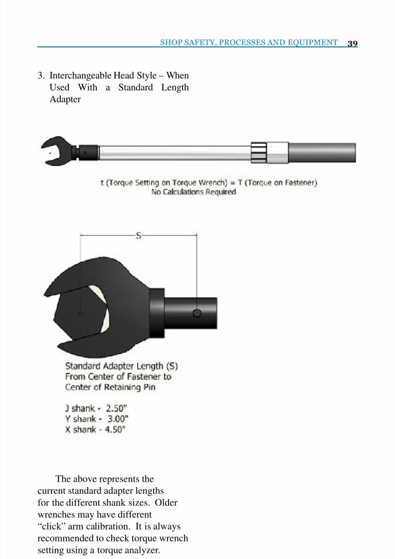
3. Interchangeable Head Style – When
Used With a Standard Length
Adapter
The above represents the
current standard adapter lengthsfor the different shank sizes. Older
wrenches may have different
“click” arm calibration. It is always
recommended to check torque wrench
setting using a torque analyzer.

7/25/2019 Lmoa2013 Book Web Final
http://slidepdf.com/reader/full/lmoa2013-book-web-final 42/252
40 LOCOMOTIVE MAINTENANCE OFFICERS ASSOCIATION
Torque Wrench Verication
When using torque wrenches,
it is essential that their accuracy ischecked on a regular basis. These
testers can be used for periodic
wrench calibration and also are
helpful in checking accuracy of
torque calculations when using
adapters as described above.
Tesco Torque Wrench Tester – T18961
This tester operates between 30.0
and 1500.0 Nm (22.0 to 1106.0 Ft-lbs)
Guaranteed classication toBS7882:2008, Class 1 or better over
the primary calibration range (20% to
100% of full scale), Class 1 equates to
+/-0.5% of reading
This electronic tester can be used
in conjunction with adapter sets that are
available in ranges of both standard andmetric sizes.
Tesco Standard Adapter Set
(1/2” through 1-1/4”)
T57580
Tesco Metric Adapter Set
(6 mm through 32 mm)
T86060

7/25/2019 Lmoa2013 Book Web Final
http://slidepdf.com/reader/full/lmoa2013-book-web-final 43/252
SYSTEMS FOR
• BlASTING
• PAINTING
• WASHING
• SANDING
•
REP IR
• MAINTENANCE
•
Provide a safer
work
env
ironment
• mprove positioning
• Reduce fatigue
• Increase capacity and save time
• Total product ccess
• igh return on investment
• OSHA ANSI compli nt

7/25/2019 Lmoa2013 Book Web Final
http://slidepdf.com/reader/full/lmoa2013-book-web-final 44/252
42 LOCOMOTIVE MAINTENANCE OFFICERS ASSOCIATION
INTRODUCTION
On August 22, 2005, our
Mechanical Team began acommunication campaign called
“Mechanical Seven Safety
Absolutes”. These seven areas have
the greatest potential for loss of life
or severe, possibly career ending
injuries. Through this campaign, we
review the critical rules and policies
associated with these topics.
Objectives of Safety Absolutes
1. Understand the signicance of these
critical tasks
2. Emphasize individual responsibility
in eliminating at-risk behavior
3. Provide supervisors with the knowl-
edge and tools to address specic at-
risk behavior
4. Provide all Mechanical employees
with the knowledge to identify and
correct at-risk work behaviors
The Seven Safety Absolutes include:
• Blue Signal Protection
• Lockout/Tagout
• Jacking Equipment• Vehicle Operations
• Fall Protection
• Crane Operations and Rigging
• Locomotive and Car Movement
Blue Signal Protection
Proper Blue Signal Protection must
be in place prior to inspecting,testing, repairing, or servicing
rolling equipment. Without proper
protection, workers would be exposed
to potential serious injury or death
from moving equipment.
Mechanical Seven Safety
Absolutes-BNSF Railway Prepared by:
Ron Hennessey-BNSF

7/25/2019 Lmoa2013 Book Web Final
http://slidepdf.com/reader/full/lmoa2013-book-web-final 45/252
SHOP SAFETY, PROCESSES AND EQUIPMENT 43
Lockout/Tagout (LOTO)
LOTO must be used whenever
maintaining, repairing or servicingequipment or machinery that could un-
expectedly start-up, energize, or release
stored energy and the work being per-
formed involves:
• Removing or bypassing guards or
other safety devices
• Placing any part of your body in the
point of operation• Placing any part of your body in the
danger zone during equipment cycle
Jacking Equipment
Proper procedures must be used
whether jacking equipment on theroad with portable jacks or in the
shop with oor jacks. Never jack
equipment if you’re unsure it can be
done safely. Take the time to evaluate
the risk and involve your supervisor
in determining the safe course of
action

7/25/2019 Lmoa2013 Book Web Final
http://slidepdf.com/reader/full/lmoa2013-book-web-final 46/252
44 LOCOMOTIVE MAINTENANCE OFFICERS ASSOCIATION
Vehicle Operations
Proper operation of all motor vehicles
to include trucks, automobiles, utilityvehicles, and ATVs is essential. All
operators must have proper training
and authorization prior to operating
any type of vehicle.
Fall Protection
Injury from falls has the potential
to be a life changing event and eachyear injuries from falls rank at or near
the top in causes of fatalities at home
and at work. They can be prevented by
proper use of fall protection methods
and by following BNSF Safety Rules
and Policies

7/25/2019 Lmoa2013 Book Web Final
http://slidepdf.com/reader/full/lmoa2013-book-web-final 47/252
SHOP SAFETY, PROCESSES AND EQUIPMENT 45
Crane Operations and Rigging
Cranes, boom-equipped vehicles,
hoists, and rigging are used in compli-ance with manufacturer’s instructions
and BNSF Railway requirements.
Locomotive and Car Movement
Moving locomotives and cars in
mechanical limits could easily beconsidered the most hazardous job
we do. The size and weight of these
huge pieces of equipment coupled
with movement creates the potential
for devastating consequences if not
handled safely. Proper procedures
must be used when moving or
spotting cars and locomotives.
7/25/2019 Lmoa2013 Book Web Final
http://slidepdf.com/reader/full/lmoa2013-book-web-final 48/252
46 LOCOMOTIVE MAINTENANCE OFFICERS ASSOCIATION
Communication
In addition to the brieng
information, observation checklistswere distributed to identify the key
elements required to perform these
activities safely. These checklists are
utilized by all employees during Work
Practice Observations to identify and
correct any at-risk behavior that may
lead to injury. Supervisors also focus
their operations testing and employeesafety contacts in these areas.
Conclusion
We are working to reduce at-
risk behaviors by raising employees’awareness and understanding of the
rules and policies that will assure
their safety and that of their co-
workers. We believe all accidents
and injuries are preventable and that
one day we will achieve an injury-
free workplace. Knowledge and
compliance with our MechanicalSafety Absolutes will help us in this
effort.

7/25/2019 Lmoa2013 Book Web Final
http://slidepdf.com/reader/full/lmoa2013-book-web-final 49/252
Technology forRailway Wheelsets
A Member of ...
Keeping the World on Track for over 100 Years
www.smtgroup.com
Albany, New York

7/25/2019 Lmoa2013 Book Web Final
http://slidepdf.com/reader/full/lmoa2013-book-web-final 50/252
48 LOCOMOTIVE MAINTENANCE OFFICERS ASSOCIATION
When selecting the proper train
wash there are a number of consider-
ations to take into account:• Site Conditions (Figure 1)
• Train Car Style (Figures 2 and 3) –
Overhead Catenary and Third Rail
• Number of Vehicles
• Frequency of Wash (Figure 4)
• Water Quality• Regulations
PROPER TRAIN WASHING-
More Than Just Brushes and Nozzles
Prepared by:
Al Gould and Tracy Briggs, Interclean Equipment, Inc.
Figure 1 Figure 2
Figure 3 Figure 4

7/25/2019 Lmoa2013 Book Web Final
http://slidepdf.com/reader/full/lmoa2013-book-web-final 51/252
SHOP SAFETY, PROCESSES AND EQUIPMENT 49
There are many solutions:
• Chemical – Soap (Figure 5) – You
need to understand the details ofeach problem or application and
then design the best wash solution.
Figure 6 shows a brushed alumi-
num train car with iron oxide stain-
ing and gure 7 shows the train car
after it was cleaned with the correct
chemistry. Typically a train wash
will use two chemicals (acid andalkaline)-see gure 8.
Figure 5
Figure 8
Figure 6 Figure 7

7/25/2019 Lmoa2013 Book Web Final
http://slidepdf.com/reader/full/lmoa2013-book-web-final 52/252
50 LOCOMOTIVE MAINTENANCE OFFICERS ASSOCIATION
Figure 10Figure 9
Figure 11
• Friction and/or High Pressure
(Touchless and Hybrid) –It is some-
times almost impossible to cleanwith brushes (friction). In these
situations, touchless cleaning is the
only alternative (Figure 9). Figures
10 and 11 show a train wash system
(hybrid cleaning) using touchless
cleaning for the front and rear of the
train car and sprays from the top in-
stead of the sides. The sides are stillcleaned with brushes. This system
works well with OCS and third rail
passenger train cars. Some of the ad-
vantages of Hybrid Cleaning (Fig-ure 12) are that the brushes rotate,
but do not move into the path of the
train therefore preventing damage to
the train. Also, the wash equipment
requires much less maintenance and
allows for different types of trains to
be washed on the same line without
modifying the design.
Figure 12

7/25/2019 Lmoa2013 Book Web Final
http://slidepdf.com/reader/full/lmoa2013-book-web-final 53/252
SHOP SAFETY, PROCESSES AND EQUIPMENT 51
• Reclamation System-
The water reclaim system is made
up of:
1. Settling Pit
2. Filtration
3. Separation
4. Circulation
5. Aeration
6. PH Neutralization
Many new train wash systems that
are designed are incorporating settling
systems for the wastewater collection
regardless if the systems use fresh or re-
cycled water. In some cases where the
regulatory rules are already very strict,
wash manufacturers are partnering with
companies to provide treatment systemsspecically designed to address the oils,
suspended solids and heavy metals in
the waste water stream. With settling
pits present, treatment systems can veryeasily be added to the system at a later
time (Figure 13 and 14).
The cyclone separator and
550-gallon tank cyclone (Figure 15) are
designed to separate dirt on continuous
basis and ush separated dirt from their
bottom drainage ports. All separated
direct with aerated water is constantlybeing sent to the dirty end of the set-
tling pit to concentrate the solids at a
single point in the treatment system.
This style of recycling tanks rarely
will need to have the accumulated dirt
build up ushed out. The settling pit
is the only component that needs to be
cleaned out on a regular basis.
Figure 15
Figure 14
Figure 13

7/25/2019 Lmoa2013 Book Web Final
http://slidepdf.com/reader/full/lmoa2013-book-web-final 54/252
52 LOCOMOTIVE MAINTENANCE OFFICERS ASSOCIATION
Odors:
The constant exchange of water
between the clean end and the dirty end
of the pit keeps aerated water always
moving throughout the system. This
guarantees that the captured water in
the reclamation system does not devel-
op objectionable odors usually associ-ated with recycling systems.
The odors within recycled water
are caused by a lack of oxygen and the
bacteria going anaerobic. The circula-
tion pump keeps the discharge from the
wash system constantly owing, oxy-
genating the re-cycled wash water.
Recycling systems also have the
ability to add enzymes, bacteria and
nutrients to the recycled water. This
Enhanced Biological Water Treatment
System has proven to greatly reduce
oils, greases, and other organic waste
loading in the recycled water. This pro-
cedure is the same as many municipal
wastewater treatment plants utilize. It
also addresses a major issue in meeting
regulations for discharge to sanitary
sewer.
The settling pit (gure 16) is de-signed for passive settling and mini-
mum maintenance. It has an automatic
lter backwash, an oil-water separator
and an automatic level sensor and ad-
justment feature.
After the reclaimed water passes
through the setting pit, it is ltered
through an InterScreen and then pro-
cessed through two cyclonic separators
for additional solids removal. A section
of an InterScreen lter is displayed in
gure 17.
Figure 16
Figure 17

7/25/2019 Lmoa2013 Book Web Final
http://slidepdf.com/reader/full/lmoa2013-book-web-final 55/252
SHOP SAFETY, PROCESSES AND EQUIPMENT 53
Figure 18 depicts the separation/
circulation and aeration portions of the
system.Figure 19 shows a computer
screen which provides a clear, graphic
illustration of the water reclaim system
Figure 20 depicts the rinse process
to remove chemicals while at the same
time trying not to cause spotting on the
train car. Spotting is caused by miner-
als in the rinse water. Some people rec-
ommend using a softener for their rinse
arch to remove calcium. However, for
every calcium ion a softener takes out,it is replaced with two sodium ions.
Therefore, you are increasing the total
mineral count. A reverse osmosis sys-
tem is the best way to reduce mineral
spotting.
Figures 21-25 provides sample
systems
Figure 18
Figure 20
Figure 19

7/25/2019 Lmoa2013 Book Web Final
http://slidepdf.com/reader/full/lmoa2013-book-web-final 56/252
54 LOCOMOTIVE MAINTENANCE OFFICERS ASSOCIATION
Figure 22
Figure 25
Figure 21
Figure 23 Figure 24

7/25/2019 Lmoa2013 Book Web Final
http://slidepdf.com/reader/full/lmoa2013-book-web-final 57/252
25.23
cn..nanoog•
V...y
On . • PO
ao . 25
~ n t s t o n e Geotg a 3072 • u A
~ • 7 0 6 ) 8 ~ 9 7
Fa .. 17 820-9802
7/25/2019 Lmoa2013 Book Web Final
http://slidepdf.com/reader/full/lmoa2013-book-web-final 58/252
56 LOCOMOTIVE MAINTENANCE OFFICERS ASSOCIATION
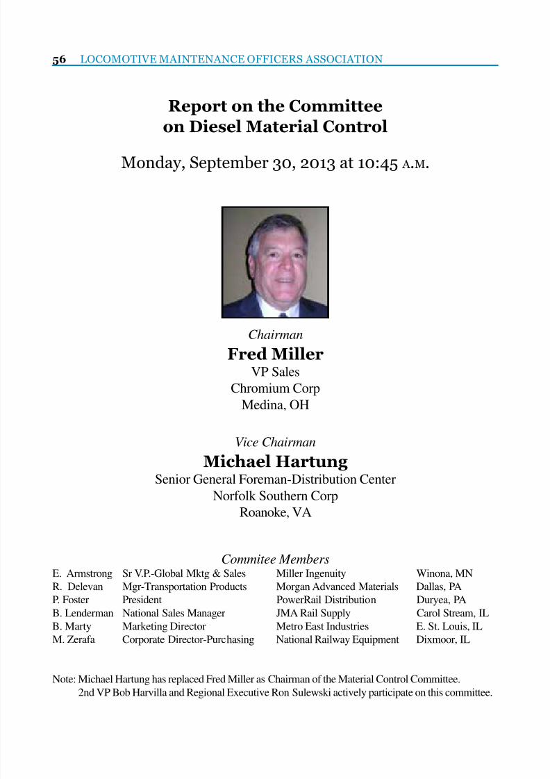
Report on the Committee
on Diesel Material Control
Monday, September 30, 2013 at 10:45 A .M.
Chairman
Fred MillerVP Sales
Chromium Corp
Medina, OH
Vice Chairman
Michael HartungSenior General Foreman-Distribution Center
Norfolk Southern Corp
Roanoke, VA
Commitee MembersE. Armstrong Sr V.P.-Global Mktg & Sales Miller Ingenuity Winona, MN
R. Delevan Mgr-Transportation Products Morgan Advanced Materials Dallas, PA
P. Foster President PowerRail Distribution Duryea, PA
B. Lenderman National Sales Manager JMA Rail Supply Carol Stream, IL
B. Marty Marketing Director Metro East Industries E. St. Louis, IL
M. Zerafa Corporate Director-Purchasing National Railway Equipment Dixmoor, IL
Note: Michael Hartung has replaced Fred Miller as Chairman of the Material Control Committee.2nd VP Bob Harvilla and Regional Executive Ron Sulewski actively participate on this committee.

7/25/2019 Lmoa2013 Book Web Final
http://slidepdf.com/reader/full/lmoa2013-book-web-final 59/252
DIESEL MATERIAL CONTROL 57
P E R S O N A L H I S T O R Y
Fred Miller
Fred Miller began his railroad career at Teledyne Metal
Finishers in 1969. He continued his career at ChromiumCorporation, Durox and RELCO. After a very brief retirement
Fred rejoined Chromium Corporation as VP Sales. His
responsibilities include sales to all the North American Railroads.
He has an ofce at Chromium’s facility in Cleveland, Ohio along
with his home ofce in Medina, Ohio. Fred and his wife Marsha
combined families about 13 years ago and have 7 children. Their
9 grandchildren keep them busy and young at heart.

7/25/2019 Lmoa2013 Book Web Final
http://slidepdf.com/reader/full/lmoa2013-book-web-final 60/252
58 LOCOMOTIVE MAINTENANCE OFFICERS ASSOCIATION
The Diesel Material Control Committee
would like to thank David Bird and the
Kansas City Southern Rwy for hosting a
meeting in Shreveport, LA on
February 11-12, 2013.
The Committee would also like to extend
their gratitude to the Norfolk Southern
for hosting a presentation at the Southern
Southwestern Rwy Club in Altoona, PA on
June 20-22,2013.
The Committee also conducted a conference
call on March 8, 2013.

7/25/2019 Lmoa2013 Book Web Final
http://slidepdf.com/reader/full/lmoa2013-book-web-final 61/252
DIESEL MATERIAL CONTROL 59
FACTS
The recycling industry employs
more than 130,000 people in the
U.S. and generates more than $77Billion in sales each year. Recycled
materials account for more than $30
Billion in export sales annually, with
most of the transportation to ports
provided by Rail in containerized
units. Recycling saves about 500 M
tons of CO2 gas annually. One auto
saves 502 gallons of gas and 8,811 lbsof CO2. Four tires save 18 gallons of
gas and 323 lbs of CO2.
More than 60% of iron and steel
made in the U.S. is produced with
recycled metals-much of it hauled by
Railroads to the reners. Recycling
one ton of aluminum cans conserves
36 barrels of oils. In 2010, theU.S. recovered 51.5 million tons
of paper, which was 64% of paper
consumed-334 lbs of paper per person
in the U.S. Recycled scrap copper is
utilized to produce 50% of all copper
produced in the US each year.
BENEFITS• Prevents emissions of air and water
pollutants
• Reduces greenhouse gas emissions
• Saves energy
• Supplies valuable materials to the
industry
• Stimulates the development of
greener technologies
• Conserves resources for our chil-
dren’s future• Cost control
The benets add up
• 132 million metric tons of scrap ma-
terial processed every year
• 74 million tons of iron and steel
• 47 million tons of paper
• 4.6 million tons of aluminum• 3.5 million tons of electronics
• 1.8 million tons of copper
• 1.2 million tons of lead
Railroad Waste Streams
• Batteries
• Cross Ties
• Electronic equipment• Fluorescent bulbs/lamps
• Plastics
• Steel
• Oils
• Copper
• Wood pallets
• Paper
• Cardboard• Aluminum
• Locomotives/Cars
• Locomotive/Car Parts
Recycling of Materials
Prepared by:
Mike Hartung, Norfolk Southern

7/25/2019 Lmoa2013 Book Web Final
http://slidepdf.com/reader/full/lmoa2013-book-web-final 62/252
60 LOCOMOTIVE MAINTENANCE OFFICERS ASSOCIATION
Wood Pallet Recycling
Contributors; Linda Szilagyi (CSX)
and Fred Miller (Chromium Corp)
Wood Pallet Recycling
Pallets accumulate around yards
from material shipments. They
occupy valuable real estate space and
are a safety hazard.
Auger Technology – A Solution to BulkWaste Handling (Figures 1&2)
Advantages of Auger Technology for
recycling applications are:
• Reduces volume for transportation
efciency
• Reduces environmental impact
• Reduces labor times
• Increases safety at the site
Pallet Shredder Benets
• Auger screw not effected by metal
(nails and tie plates)
• Reduces the number of hauls up
to 75% by compacting eight times
more material into standard 40 yard
containers
• Shredded wood recycled as boiler
fuel or mulch
Paper and Cardboard Recycling
(Figure 3)
• Ofce paper products including
copy paper, newspaper, envelopes,
cardboard, and magazines are re-
cycled• CSX utilizes blue bins called “slim
jims” with blue tops and are placed
in various locations for collection
• CSX also utilizes small desk side
bins for recycling in ofce areas
• Auger shredders can also be used
for cardboard
Recycling Copper in the Rebuild
Process
Contributor: Ron Sulewski (Rail Prod-ucts International)
Copper Recycling
Recycling is the basis of
electrical rotating rebuild business.
Almost 100% reuse of UTEX core
exchange. Regularly see electrical
components originally built new 20-40 years ago – recycling at its best.
Process Initiation
Most recycling programs start
with partnering with processors,
converters and mill operators.
RPI’s process is as follows: (Figures4&5)
Collect and separate “spent”
copper from motors, generators,
armatures and coils. The “spent
copper: is then sent to a converter-
processor to chop and separate
number one scrap from number two
scrap copper. After all the insulation
is removed, the material is chopped,
shredded or mechanically processed
for the next stage.
Material is then melted which
further renes base material. The
“melt” is then classied and blended
with new base metal (if required) in
order to meet acceptable metallurgy.
This material then becomes cathodebillets. (Figure 6) The billets are
then converted at the mill using a
continual cast process into copper
rod. The rod is then processed in one
of two wire mills into usable wire of
various sizes for multiple Railroad
products. (Figure 7)

7/25/2019 Lmoa2013 Book Web Final
http://slidepdf.com/reader/full/lmoa2013-book-web-final 63/252
The Secret is Coming Down the Track...POWERRAIL IS CELEBRATING 10 YEARS OF EXCELLENCE!
www. powerrail.com™ | 570.883.7005
Celebrating 10 Years of Excellence!
10 Years of Delivering Results!We would like to sincerely THANK all of our loyal customers and friends for their support over the past 10 years.
Without you, we would not be who we are today - An AAR M-1003 Quality Corporation offering a full line of Locomotive
Parts and Components. We are Unique Manufacturer and full-service stocking company with multiple locations throughout
North America offering a full range of New or Our Proven True Blue™ Remanufactured-Unit Exchange Components.
We will continue to strive to exceed your expectations, while delivering products and services that
meet exemplary standards of Quality, Service, Delivery and Value!

7/25/2019 Lmoa2013 Book Web Final
http://slidepdf.com/reader/full/lmoa2013-book-web-final 64/252
62 LOCOMOTIVE MAINTENANCE OFFICERS ASSOCIATION
Other Cost Benets
This recycle process enables
companies to stock a large inventorypool of usable copper for numerous
products. RPI does not buy nished
wire products because of the volatile
price based on market conditions.
Cost is controlled by managing the
pool volumes based on market prices
(BUY low-SELL high).
Cost Control
The only actual cost experienced
is the processing fees which are fairly
stable. Number two copper is not
recycled as this contaminates the
melt, which requires new material to
be added. Number two copper (very
small amounts) is sold to offset theprocessing and transportation costs.
Filter Crushing/Recycling
(Figures 8 & 9)
Contributor: Bob Harvilla
(PowerRail Distribution)
Recycling Locomotive Filters/Lube Oil
Filters can be crushed to:
• Reduce waste that has to be handled
• Recycle lube oil
• Sell lube oil to reclaimers
• Utilize lube oil for heating
Drained 36” oil lter can be
crushed to 6” and will yield ¾ gallon
of recyclable lube oil. This reduceswaste management and maximizes
lube oil recycling benets.
Use Oil Recycling
Contributors: Eric Fonville (NS) and
Mike Hartung (NS)
Sources:
• Locomotives and waste water
• Separator
• Operations
Two Methods:
• Sold to vendor or• Used for heating
WWTP Captured Oil
• High water content
• Sold to vendor for recycling
• Belt skimmer project to reduce wa-
ter content and improve oil quality
On-Site Disposal (Figure 10)
• The most efcient means of recy-
cling
• No off-site transportation costs
• Low maintenance costs
• Can easily be located in worker ar-
eas
Enola Locomotive Shop
Estimated annual heating fuel
consumption is 75K gallons. The
estimated annual used oil generation
is 100K gallons. Equipment has been
installed in three buildings as a pilot
program. Payback period analysis
shows ROI <two heating seasons

7/25/2019 Lmoa2013 Book Web Final
http://slidepdf.com/reader/full/lmoa2013-book-web-final 65/252
DIESEL MATERIAL CONTROL 63
(Figure 1)
(Figure 2)

7/25/2019 Lmoa2013 Book Web Final
http://slidepdf.com/reader/full/lmoa2013-book-web-final 66/252
64 LOCOMOTIVE MAINTENANCE OFFICERS ASSOCIATION
(Figure 3)
(Figure 4)

7/25/2019 Lmoa2013 Book Web Final
http://slidepdf.com/reader/full/lmoa2013-book-web-final 67/252
DIESEL MATERIAL CONTROL 65
(Figure 5)
(Figure 6)
(Figure 7)

7/25/2019 Lmoa2013 Book Web Final
http://slidepdf.com/reader/full/lmoa2013-book-web-final 68/252
66 LOCOMOTIVE MAINTENANCE OFFICERS ASSOCIATION
(Figure 8)
(Figure 9)
(Figure 10)

7/25/2019 Lmoa2013 Book Web Final
http://slidepdf.com/reader/full/lmoa2013-book-web-final 69/252
For over 75 years, we’ve provided one
source to handle all your locomotive traction
component repair, rebuild and manufacturing
needs. We recognize individual demands by
providing tailored manufacturing processes and
customized products and services to handle a
variety of unique railroad specifications.
Our high level of on-time delivery performance is
backed with a manufacturing quality that meets
ISO 9001-2008 and AAR M-1003 registrations.
No matter what your electrical component needs
are, our products will help you achieve greater
reliability and increased time on the track.
Crafted to Go the Distance

7/25/2019 Lmoa2013 Book Web Final
http://slidepdf.com/reader/full/lmoa2013-book-web-final 70/252

7/25/2019 Lmoa2013 Book Web Final
http://slidepdf.com/reader/full/lmoa2013-book-web-final 71/252
DIESEL MATERIAL CONTROL 69
Positive train control (PTC) is
a system of functional requirements
for monitoring and controlling train
movements to provide increasedsafety. Additional benets can include
increased equipment utilization,
better personnel utilization, and fuel
management platforms. The rail
safety improvement act was signed
into law on October 16, 2008 setting
a deadline of December 15, 2015,
for implementation of positive traincontrol (PTC) technology across
most of the U.S. rail network. This
paper addresses the opportunities to
improve the ordering and handling
of the material prior to installation on
locomotives.
Constant Changes to MaterialNeeds
The biggest overall challenge
described by the various railroads
that participated in this paper were
the huge variety of locomotive
applications and the ongoing changes
in the regulations and materials
available. One railroad described
their locomotive eet as a, “bunch
of snowakes,” giving a feel for the
magnitude of the challenge relative to
the number of kits needed to address
each eet. Each railroad also has
specic requirements that vary based
on install process, installers and
component suppliers. Add to that as
late as December 2012 the regulations
are still changing aggravates the
problem even more. Railroads are addressing these
issues coupled with the impending
deadlines with a couple of different
approaches. First is to provision
locomotives with the basic wiring,
antenna farms and bracketing in
anticipation of a nal push before
the implementation deadline. The plan would be to install the nal
components and test the units with
nal versions of software in the
months prior to the deadline. Another
railroad is taking the approach of
outtting the locomotives in their
entirety to validate functionality as
soon as possible. This approachassumes the basic hardware will
remain the same and the only major
changes to the system will be software
related. This approach has already
proven less than perfect, as the new
requirements are changing cabinet
requirements for all installations, e.g.
locking cabinets for verication of
equipment integrity.
All of these factors (and MANY
more) have made material ordering,
handling and installation frustrating
for the railroads as well as the supply
community. While many of the parts
themselves are completely new to the
Material Solutions for Implementing PTC
Prepared by:
Eric Armstrong, Miller Ingenuity and Brian Marty, Metro East Inc

7/25/2019 Lmoa2013 Book Web Final
http://slidepdf.com/reader/full/lmoa2013-book-web-final 72/252
70 LOCOMOTIVE MAINTENANCE OFFICERS ASSOCIATION
industry, all of the part numbers being
created are new. Standardization
of process at least within the largerailroads is the clear recommendation
however with changes still coming in
it will not resolve the problem, only
manage it better.
To Kit or not to Kit?
The question of kitting the
various parts leads to the samechallenges normally found in the
use of kits. A major issue with this
particular project is that with the
kits in the eld so far the persistent
changes have caused a lot of material
to not be used on installation and
replaced with other materials. This
means going back in to the kitsin the warehouse and removing/
replacing components before they are
delivered to the shop for installation.
Alternatively having the shop replace
the material in the kit and return the
excess to the supply department is
an option. Disposition of the excess
and unused materials has been a
problem as they tend toward wiring
harnesses and various parts that have
no application in other areas for the
railroads or the suppliers.
Pros and Cons of kitting for the
PTC project:
Pro
• Easier to control, less part numbers,standardization
• Better part management of offsite
installations
• Parts coming from multiple sup-
pliers,… coordination is simpler if
centralized
• Installers become more procient
with consistent material packaging,
thus eliminating waste and redun-dant work
Con
• Various applications creating spe-
cic part numbers that may not be
used very often
• Not everything in the kits is being
used sending the parts back to stockor paying a restocking fee to sup-
pliers
• Not all parts can be kitted because
they are not used in all applications
Storage
Most of the railroads have
been busy over the past few yearsutilizing lean management processes,
and operations for efciency
improvements. A major improvement
has been a reduction in space
needed in warehouse operations.
Unfortunately the rapid onset of the
PTC program and oncoming deadlines
have required the railroads to tactically
respond to an increased need for space
to store these products. The sheer
scope of this implementation project is
daunting and most of the planning has
been, “on the y.”
In the changing landscape
lead times and ramp up time are
inconsistent at best and require
more material on hand than would be normal for projects this large.
Aggravating the limited storage space
issues even more is that many of the
programs are lagging behind schedule
leaving more material in supply
operations awaiting application.

7/25/2019 Lmoa2013 Book Web Final
http://slidepdf.com/reader/full/lmoa2013-book-web-final 73/252
NATIONAL RAILWAY EQUIPMENT CO.888-823-8391 | WWW.NATIONALRAILWAY.COM
• New Locomotive Design & Build
• Used Locomotive Sales
• Re-Powered Locomotives
• Green Locomotives• Leasing
• New Locomotive Parts
• Fabrication
• Electronics
• Wheel & Axel
• Engine Re-Manufacturing
• Inspections
• Field Services
• Paint & Design
• Engineering Services• Wreck Repair
• Deck Overhaul
• Power Upgrades
• Cab & Comfort
• Consultation
FROM START TO FINISH

7/25/2019 Lmoa2013 Book Web Final
http://slidepdf.com/reader/full/lmoa2013-book-web-final 74/252
72 LOCOMOTIVE MAINTENANCE OFFICERS ASSOCIATION
The key for resolving many of
these issues has been to determine
which materials can be stored insideversus which can be left in the
weather. The antenna farms have
had good success stored outside
and in their original crating can be
stacked. A lot of the material in kits
need to stay dry but can be stored
outside if left in original packaging
and covered. Small parts will needto go into normal inventory in the
warehouse. Excess materials will
need to remain indoors until nal
disposition is determined.
Budget Challenges
Excess materials become
problematic when the budget isfactored into the equations. Many
of the items are on the capital budget
and do not effect the inventory cost
the same as expense items. Taking
them out of inventory, removing
them from kits, holding on to them or
scrapping them all present problems
when balancing the inventory. All
railroads have this challenge and
need to work out a process with their
nance department for each of the
scenarios.
When working with some of the
class one railroads, smaller railroads
and installation contractors need to
ask about discounts available based
on contract pricing for materials attheir class one partners.
Other Issues
There are a number of
miscellaneous concerns expressedin discussions regarding PTC
implementation. Notably the
magnitude of the project initially
put huge demands on manpower
for entering part numbers, setting
up processes and general planning.
Most of the start up issues have
been tackled but supply operationsis still tasked on a daily basis with
increased numbers of transactions,
part number management, inventory
challenges, etc. all in the face of
limited human resources dedicated to
PTC implementation. Some railroads
are beginning to see that installation
and maintenance of PTC is going torequire long-term human assets to
support the project in an on-going
basis.
As 2015 nears many of the
units being provisioned now will
create a big demand for equipment
and outtting. Planning now
and communicating your plan
to your supplier or for supplier
to communicate to the customer
base will help to ease the stress for
everyone as we move for the nal
date for going live with PTC.
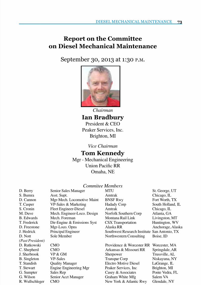
7/25/2019 Lmoa2013 Book Web Final
http://slidepdf.com/reader/full/lmoa2013-book-web-final 75/252
DIESEL MECHANICAL MAINTENANCE 73
Report on the Committee
on Diesel Mechanical Maintenance
September 30, 2013 at 1:30 P.M.
Chairman
Ian BradburyPresident & CEO
Peaker Services, Inc.
Brighton, MI
Vice Chairman
Tom KennedyMgr - Mechanical Engineering
Union Pacic RR
Omaha, NE
Commitee MembersD. Berry Senior Sales Manager MTU St. George, UTS. Bumra Asst. Supt. Amtrak Chicago, IL
D. Cannon Mgr-Mech. Locomotive Maint BNSF Rwy Fort Worth, TXT. Casper VP-Sales & Marketing Hadady Corp South Holland, ILS. Cronin Fleet Engineer-Diesel Amtrak Chicago, ILM. Duve Mech. Engineer-Loco. Design Norfolk Southern Corp Atlanta, GAB. Edwards Mech. Foreman Montana Rail Link Livingston, MTT. Frederick Dir-Engine & Emissions Syst CSX Transportation Huntington, WVD. Freestone Mgr-Loco. Opns Alaska RR Anchorage, AlaskaJ. Hedrick Principal Engineer Southwest Research Institute San Antonio, TXD. Nott Sole Member Northwestern Consulting Boise, ID(Past President)
D. Rutkowski CMO Providence & Worcester RR Worcester, MA
C. Shepherd CMO Arkansas & Missouri RR Springdale, ARJ. Sherbrook VP & GM Sherpower Trussville, ALB. Singleton VP-Sales Transpar Corp Niskayuna, NYT. Standish Quality Manager Electro Motive Diesel LaGrange, ILT. Stewart Engine Engineering Mgr Peaker Services, Inc Brighton, MIG. Sumpter Sales Rep Casey & Associates Ponte Vedra, FLG. Wilson Senior Acct Manager Graham White Mfg Salem VAR. Wullschleger CMO New York & Atlantic Rwy Glendale, NY

7/25/2019 Lmoa2013 Book Web Final
http://slidepdf.com/reader/full/lmoa2013-book-web-final 76/252
74 LOCOMOTIVE MAINTENANCE OFFICERS ASSOCIATION
P E R S O N A L H I S T O R Y
Ian Bradbury
Ian was born in Sheffield,
England and obtained a B.Sc. inMathematics from UEA and a Ph.D.
in Statistics from the University
of Birmingham, England before
coming to the U.S. He spent 4 years
teaching statistics at UT Dallas and
Oakland University, Michigan, and
7 years leading GM Powertrain’s
engine design quality effort before joining Peaker Services (PSI) as
President in 1997. Ian acted as
trustee for the first leveraged ESOP
transaction in 2000 and PSI is now
a 100% employee owned company.
PSI’s historical core for over 40
years has been service and upgrade
of EMD engines and controls in
locomotive, marine and power
generation. Since joining PSI, Ian
had led the effort to diversify the
company into controls for otherdiesel, natural and bio-gas engines,
steam and gas turbines. He obtained
an MBA from the University of
Michigan in 2003. Ian is a member
of ASME and serves on the W.
Edwards Deming Institute advisory
board.
Ian and his wife of 22 years,Kathy, are both keen mountain
bikers and craft beer consumers.
Kathy teaches yoga and ‘enhance
fitness’ as well as smoking a mean
brisket. They have two sons - James
(21) and George (19). James plans
to pursue a career in automotive
journalism, and George, in
illustration and graphic design.

7/25/2019 Lmoa2013 Book Web Final
http://slidepdf.com/reader/full/lmoa2013-book-web-final 77/252
DIESEL MECHANICAL MAINTENANCE 75
The Diesel Mechanical Maintenance
Committee would like to thank MTU for
hosting our committee meeting in Aiken,
South Carolina on March 14, 2013 and for
the tour of their engine plant in Aiken.
Special thanks to Joerge Klisch, Operations
Mgr and Jens Baumeister, Plant Manager.
Thank you to Knoxville Locomotive Worksfor hosting dinner for the committee on the
evening of March 13th and for having their
MTU powered locomotive on display at the
siding in Aiken.
The committee would also like to thank
S. Bumra and Amtrak for setting up a
conference call for the committee on
December 6, 2012 and previousconference calls.

7/25/2019 Lmoa2013 Book Web Final
http://slidepdf.com/reader/full/lmoa2013-book-web-final 78/252
76 LOCOMOTIVE MAINTENANCE OFFICERS ASSOCIATION
Introduction:
Pacic Harbor Line (PHL), an
Anacostia Company, is a short line
railroad that operates the switching
services for the Ports of Los
Angeles and Long Beach handling
approximately 10% of all the
intermodal containers that arrive orleave the United States.
The current locomotive eet
replaces EMD two-cycled locomotives
that were up to 40 years old. Today
PHL operates and maintains 23 of the
most modern and emissions friendly
locomotives of any short line railroad
in North America:• 4 each 3GS21B - 2,100 HP 4-axle
EPA Tier 3 Gen Set Locomotives –
National Railway Equipment
• 2 each 3GS21C – 2,100 HP 6-axle
EPA Tier 3 Gen Set Locomotives –
National Railway Equipment
• 2 each MP20B-3PR – 1,950 HP
4-axle EPA Tier 3+ Locomotives –Progress Rail Services
• 14 each MP20C-3PR – 1,950 HP
6-axle EPA Tier 3+ Locomotives –
Progress Rail Services
• 1 each PR30C – 2,800 HP 6-axle
EPA Tier 4 Locomotive – Progress
Rail Services
The purpose of this paper is to
discuss the seventeen (17) locomotives
delivered by Progress Rail Services
that are equipped with after-treatment
systems.All seventeen (17) locomotives
were delivered as certied EPA Tier 2
locomotives. The two PR20B, fourteen
PR20C and one PR30C are all re-
powered locomotives equipped with
single engine prime movers and after-
treatment equipment to meet their
respective funded emissions levelswhich are more stringent than the as
delivered EPA Tier 2 requirements.
• The MP20B-3PR and MP20C-3PR
locomotives, with their emissions
equipment, are required by fund-
ing to meet EPA Tier 3 emissions
standards with the exception of PM,
which must not exceed 0.36 gramsper brake horsepower-hour (g/bhp-
hr), for their useful life.
• The PR30C locomotive with its
emissions equipment is required by
funding to meet EPA Tier 3 emis-
sions standards for its useful life but
Pacic Harbor Line
Tier 3+ and Tier 4 Re-Powered LocomotiveEmissions After-treatment Experience
Prepared by:
Dennis Nott, Northwest Consulting
James O’Kelley, Pacic Harbor Line RR
Robert Wullschleger, New York & Atlantic RR

7/25/2019 Lmoa2013 Book Web Final
http://slidepdf.com/reader/full/lmoa2013-book-web-final 79/252
DIESEL MECHANICAL MAINTENANCE 77
was delivered, and operates, as an
EPA Tier 4 locomotive.
Each locomotive is equipped withAutomatic Engine Start Stop (AESS)
and operates an average of 8.8 hours
per day (3,225 hours per year) with the
following average duty cycle:
Idle: 63.51%
N1: 9.78%
N2: 7.28%N3: 5.36%
N4: 4.91%
N5: 3.53%
N6: 2.42%
N7: 1.23%
N8: 1.99%
In 2006 the old EMD eet producedan estimated average of 8.03 tons of
NOx and 0.39 tons of PM per unit per
year. By contrast, the MP20B-3PR
and MP20C-PR produce an estimated
average of 4.96 tons of NOx and 0.036
tons of PM per unit per year. This is an
estimated reduction of 38% in NOx and
a 90% reduction in PM per locomotive.
The PR30C produces an estimated
1.66 tons of NOx and 0.038 tons of
PM per year. Compared with the 2006
EMD eet this is a reduction of 79%NOx and a reduction 90% in PM.
Because of increased business
since 2006, PHL is now running a
combined eet of 23 locomotives
versus the 18 older EMD locomotives
that were in service in 2006. Even with
the increase of ve locomotives, the
overall estimated annual emissionsreductions have been signicant; a
27% reduction in NOx and a 79%
reduction in PM.
Description of MP20B-3PR and
MP20C-3PR Locomotives:
The MP20B-3PR locomotives
were repowered utilizing one EMDGP38 and one GP40 locomotive core.
The MP20C-3PR locomotives are a
mixture of EMD SD40 and SD45 core
locomotives. With the exception of the
number of axles, the 14 MP20C-3PR
and the 2 MP20B-3PR locomotives are
practically identical with respect to the
prime movers and the emissions after-
treatment equipment.
Figure 1: MP20B-3PR - PHL 20

7/25/2019 Lmoa2013 Book Web Final
http://slidepdf.com/reader/full/lmoa2013-book-web-final 80/252
78 LOCOMOTIVE MAINTENANCE OFFICERS ASSOCIATION
All 16 of the locomotives areequipped with a single Caterpillar
3512C HD engine at 2,100 brake
horsepower coupled to the existing
Kato AA27918000 main alternator
running at a maximum of 1,800 RPM.
The Caterpillar 3512C HD engine, at
the time of installation, was EPA Tier
2 compliant without the after-treatmentequipment. The engine and the Kato
alternator, as well as a standard EMD
18 Kw auxiliary generator driven
off the engine Power take-off, are
mounted on a skid that was designed
by Caterpillar. The skid is isolated from
the locomotive frame.
The after-treatment on thelocomotives is a single passive
Diesel Particulate Filter (DPF) as
manufactured by Hug Engineering
of Switzerland. Caterpillar and Hug
jointly developed the DPF based on
operating experience in Europe of
similar engines in a railroad operatingenvironment.
Both the engine and the after-
treatment system can accommodate
ULSF fuel with up to 5% biodiesel.
PHL currently burns ULSF 2%
biodiesel. The 2% biodiesel is used to
provide increased lubrication for the
fuel injectors.The DPF is an 80.7” long by 55.8”
wide by 28.7” high stainless steel box
containing multiple proprietary ceramic
substrates that remove the particulates
from the exhaust. The box has one clean-
out port in the front side and two exhaust
stacks on the top near the rear. The
containment box and ceramic substratesweigh approximately 2,500 lbs.
The locomotives are not equipped
with dynamic brakes so the logical
positioning of the DPF was above the
engine. Since the DPF framework was
to be attached to the locomotive frame
Figure 2: MP20C-3PR – PHL 65

7/25/2019 Lmoa2013 Book Web Final
http://slidepdf.com/reader/full/lmoa2013-book-web-final 81/252
DIESEL MECHANICAL MAINTENANCE 79
and the engine is mounted on a skid
that allows movement, the positioning
and strength (resistance to movement)
of the DPF framework was critical to
assure that there would be minimal
movement between the engine exhaustand the DPF. The DPF is supported by
a framework of 4” X4” X 0.25” steel
tubing with four vertical members
fastened to the locomotive frame and
four angled braces (two at each end) that
are also fastened to the frame. The DPF
support framework was designed to
AAR S-580 standards and can withstandforces of 5.0 G’s longitudinally, 1.5 G’s
laterally and 2.0 G’s vertically. The DPF
is bolted to the support framework.
The DPF framework was also designed
to maximize access to the engine for
maintenance purposes.
As mentioned, the DPF has a clean-
out access in the front to periodically
remove any ash build-up because of
operation. To access this clean-out
access a side access door was placed on
the left side of the locomotive directly
behind the inertial lter hatch.
Figure 3: Front of DPF – Note Exhaust
intake in Middle,Clean Out on Right Side and Exhaust
Out at the Rear
Figure 4: Engine and DPF Support inCar Body
Figure 5: DPF Support Frame – Note;
End Bracing for Structure Not in Place

7/25/2019 Lmoa2013 Book Web Final
http://slidepdf.com/reader/full/lmoa2013-book-web-final 82/252
80 LOCOMOTIVE MAINTENANCE OFFICERS ASSOCIATION
In addition to the clean out door
the area for maintenance of the DPF
the car body hood above the DPF was
made into a hatch so that the entire
DPF can be removed at the time
the ceramic substrates require to beremoved for cleaning.
Prior to awarding the contractto Progress Rail Services to install
the Caterpillar engines and the Hug
DPF, PHL voiced concerns with 1)
engine torsional vibration damage to
the engine/main alternator coupling
because of cylinder miss-re and 2)
the use of a passive DPF that could
“plug” with soot causing excessive
backpressure on the engine if the PHLduty cycle was not high enough to
allow enough exhaust heat to clean
and regenerate the ceramic substrates.
The Caterpillar answer to the
engine/main alternator issue was to:
1) perform torsional vibration testing
of the Caterpillar designed engine/
main alternator coupling to assurethe coupling was robust and 2) add
temperature sensors to the cylinder
heads to determine “cold” cylinders
that could cause engine miss-re
and torsional vibration issues with
the engine/main alternator coupling.
Torsional vibration testing by
Caterpillar proved that the engine/mainalternator coupling was adequately
designed. Caterpillar worked with
Q-tron to feed information to the
locomotive cab QES screen should the
cylinder temperature in a cylinder drop
below a predetermined temperature
warning the crew of a potential
vibration problem due to a cylinder
miss-re.
Regarding the backpressure issue
with the DPF, Caterpillar agreed
to: 1) test the system and determine
at what exhaust temperature the
DPF would regenerate, 2) make the
turbocharger exhaust temperatures
that were being measured by the
Caterpillar engine system availableon the Q-tron control system and 3)
install backpressure monitoring on the
DPF that would report back through
the Q-tron control system. Testing by
Caterpillar determined that the exhaust
temperature at notch 3 unloaded
Figure 6: DPF Clean-out Access –
Exhaust Connection to DPF Not
Installed
Figure 7: Installing DPF with Top Car
Body Hatch Removed

7/25/2019 Lmoa2013 Book Web Final
http://slidepdf.com/reader/full/lmoa2013-book-web-final 83/252
DIESEL MECHANICAL MAINTENANCE 81
was sufcient to regenerate the DPF
ceramic substrates. Turbocharger
exhaust temperature monitoring andDPF backpressure monitoring were
also successfully integrated into the
Q-tron control system. When the
backpressure sensor reaches 6.7 kPa
the QES system will place the message
“Service DPF Soon” at the bottom of
every screen choice of the QES screen.
If the backpressure reaches 8.0 kPathe QES system will shut down the
engine. The backpressure monitoring
system fault display is a “Latching
Fault” that requires resetting a relay to
eliminate the fault message.
A benet to the DPF with the
turbocharger exhaust monitoring and
the cylinder temperature was also
realized; should a cylinder over-re
with excess fuel both the cylinder
temperature and exhaust temperaturewould raise accordingly. This will
give a warning of any excessive high
temperature or burning of excess fuel
in the DPF, which could cause a re
in the DPF.
In addition to the DPF, the
Caterpillar engine also has emissionscritical components that will require
periodic maintenance to maintain the
emissions certication. Caterpillar
requires the following maintenance
for the engine and the DPF to maintain
emissions levels (emissions equipment
highlighted in “yellow”):
Operating Fuel Burned Maintenance Requirement
Hours (Gallons)
6,000 NA Clean DPF
12,000 NA Refurbishment of DPF (clean and bake, replace
defective elements/substrates as required)
18,000 259,000 Replace electronic injectors with
remanufactured electronic injectors
18,000 259,000 Replace valves and cylinder heads with
remanufactured cylinder heads with valves
18,000 259,000 Replace turbochargers with remanufactured
turbochargers
18,000 259,000 Clean, test and reseal after-cooler cores24,000 NA Replace DPF/DOC substrates
72,000 1,036,000 Replace pistons
72,000 1,036,000 Replace piston rings

7/25/2019 Lmoa2013 Book Web Final
http://slidepdf.com/reader/full/lmoa2013-book-web-final 84/252
82 LOCOMOTIVE MAINTENANCE OFFICERS ASSOCIATION
MP20B-3PR and MP20C-3PR
Operating Experience and
Maintenance Experience:The rst locomotive was
successfully track and emissions
tested in July of 2011 and went into
service at the end of July of 2011;
the last locomotive was delivered at
the end of 2011 and went into service
mid- January of 2012. The following
picture shows the interior of one of theexhaust stacks and the interior of the
DPF after a week and a half of track
and emissions testing.
To date there have been no train
operating issues with any of the
PR20B or PR20C locomotives; they
have performed trouble free in all ofPHL’s various switching operations.
Maintenance of the locomotive
engines and after-treatment has been
virtually trouble free. PHL startedinspecting the DPF lters on a 92
day basis to assure that the ceramic
substrates were regenerating; but
while there was some soot there was
very little ash buildup in the interior
of the DPF’s and the inspection of the
DPF’s. Since no issues were found,
the DPF inspections have been movedto an annual basis for convenience,
even though the recommended clean-
out is every 6,000 hours. While there
is some soot, it is apparent that even
with the low duty cycle of the PHL
locomotives the exhaust temperatures
are high enough to burn off the
trapped particulates with very littleash accumulating.
It currently takes approximately
two man-hours to clean and inspect the
DPF. Inspection consists of opening
the car body hatch to access the DPF
inspection hatch. After opening the
inspection hatch, the interior of the
DPF is cleaned of any existing ash
and loose soot by vacuuming. After
cleaning, because the inspection
access is so small, the inspection of the
interior is made by taking pictures of
the interior. The pictures are reviewed
to make sure all loose ash and soot
has been removed and to verify the
integrity of the ceramic substrates. The
following pictures (Figures 9 through15) were from the last inspection of
PHL 66 on at 5,083 hours of operation
on February 2, 2013:
Figure 8: Inside of Exhaust Stack and
DPF after Initial Testing July, 2011

7/25/2019 Lmoa2013 Book Web Final
http://slidepdf.com/reader/full/lmoa2013-book-web-final 85/252
DIESEL MECHANICAL MAINTENANCE 83
Figure 9: Access for DPF Cleaning and
Inspection
Figure 11: Interior of DPF before
Cleaning
Figure 10: Inspection and Cleaning
Access to DPF
Figure 12: Finger Mark in Soot before
Cleaning

7/25/2019 Lmoa2013 Book Web Final
http://slidepdf.com/reader/full/lmoa2013-book-web-final 86/252
84 LOCOMOTIVE MAINTENANCE OFFICERS ASSOCIATION
Figure 13: Exhaust Diffuser in DPF
before Cleaning
Figure 15: Exhaust Stack after 5,083
Hours
Figure 14: Interior of Exhaust after
5,083 Hours

7/25/2019 Lmoa2013 Book Web Final
http://slidepdf.com/reader/full/lmoa2013-book-web-final 87/252
Engineering the future of green.
EPA Certified Emission Kit Upgrades for
EMD 645 and 710 locomotive engines.
emdiesels.com
Electro-Motive Diesel is owned by
Progress Rail Services, A Caterpillar Company

7/25/2019 Lmoa2013 Book Web Final
http://slidepdf.com/reader/full/lmoa2013-book-web-final 88/252
86 LOCOMOTIVE MAINTENANCE OFFICERS ASSOCIATION
When Figure 15 is compared to
Figure 8, it is apparent on how clean
the exhaust of the locomotives hasbeen over the 5,000 hours.
A minor issue has been
backpressure sensor calibration. As
with any new design, the sensors
and their calibration are designed to
protect the systems they monitor; but
as always, there are products in the
population that do not act the same wayas others. Two of the 16 locomotives
consistently operate at 6.7 to 6.9 kPa
backpressure with a constant fault
message on the QES screen to service
the DPF. Consideration is being given
to adjust the acceptable fault display
backpressure up to 6.9 kPa.
PHL also performs a load teston an annual basis to check the
backpressure. The backpressure sensor
is removed and a digital read out test
gauge and sensor are put in its place.
This is to verify that the backpressure
is <6.7 kPa at full horsepower.
In addition, there have been no
miss-re faults (cold cylinders) to
date. Inspection of the engine/main
alternator coupling indicates that there
have been none.
Description of PR30C Locomotive:
The PR30C was rebuilt using
an EMD SD40-2 locomotive core.The locomotive is equipped with a
Caterpillar 3516C-HD engine coupled
to a Marathon model 1020 main
alternator. The emissions control
equipment consists of a Selective
Catalytic Reduction (SCR) system and
a Diesel Oxidation Catalyst (DOC).
Locomotive control is provided by aZTR Nexsys microprocessor system.
Both the engine and the after-treatment
system are designed to burn ULSF
fuel with up to 5% biodiesel.
The engine and the main alternator
are skid mounted and the skid is
fastened to the locomotive frame. The
SCR system consists of a SCR/DOCunit mounted in the Clean Emissions
Module (CEM) which is on the top of
the locomotive long hood just behind
the dynamic brake, a Diesel Exhaust
Fluid (DEF or Urea) tank behind the
fuel tank and a DEF dosing control
cabinet mounted in the rear interior of
the long hood between the engine and
the air compressor.

7/25/2019 Lmoa2013 Book Web Final
http://slidepdf.com/reader/full/lmoa2013-book-web-final 89/252
DIESEL MECHANICAL MAINTENANCE 87
Figure 16: PR30C PHL 40
Figure 18: Engine with DOC/SCR
above Engine
Figure 17: SDCR/DOC behind Dynamic
Brake and Urea Tank behind Fuel Tank
Figure 19: Exhaust Connection to DOC/
SCR

7/25/2019 Lmoa2013 Book Web Final
http://slidepdf.com/reader/full/lmoa2013-book-web-final 90/252
88 LOCOMOTIVE MAINTENANCE OFFICERS ASSOCIATION
Clean Emissions Module (CEM):
The CEM (Figure 20) consists
of the following devises: the DOC,the SCR, NOx sensors, exhaust
temperature and pressure differential
sensors, the DEF nozzle and the engine
exhaust inlet. The CEM is 80.8” long
by 94.3” wide by 32.8” high and
weighs 5,950 lbs. Lifting connections
are located at the bottom four corners
of the CEM so that it may be removedif needed.
Figure 20: CEM
Top View:
1. Diesel Oxidation Catalyst (DOC)
2. Selective Catalyst Reduction (SCR)
3. Nitrogen Oxide Sensor Assemblies
4. Temperature and Differential Pressure
Sensor Assemblies
Bottom View:
5. Diesel Exhaust Fluid (DEF) Nozzle
6. Exhaust Inlet

7/25/2019 Lmoa2013 Book Web Final
http://slidepdf.com/reader/full/lmoa2013-book-web-final 91/252
DIESEL MECHANICAL MAINTENANCE 89
The diesel engine exhaust,
one on each side of the CEM, rst
ows through the DOC’s and then
through the SCR system. The DOC’s
convert NO in the exhaust to NO2
and remove as much of the SolubleOrganic Fraction (SOF) as possible
from the PM. Converting the NO to
NO2 is very important as the NO
2is
more reactive than NO in the SCR
and higher conversion efciency is
possible with minimal amounts of
DEF. The reduction of the SOF keeps
the PM emissions to a minimum andkeeps any “wet” PM from sticking to
the face of the SCR.
There is no ammonia “clean-
up” catalyst after the SCR. The CEM
control system is used to minimize
the ammonia slip using the fact that
ammonia reacts on a NOx sensor and
will give a false high NOx level. Whathappens is the control system will add
DEF and watch the SCR outlet NOx
emissions drop compared to the inlet
NOx. When the DEF injection rate
continues to increase, but the NOx
sensor shows NOx going up, ammonia
slip is assumed to be taking place.
The control system will then cut the
amount of DEF being used to reducethe ammonia slip. The control system
basically balances the DEF injected to
hit the NOx target without ammonia
slip.
Dosing Cabinet:
The DEF dosing cabinet controls
the DEF (Urea) output to the SCRthrough inputs from the engine and the
CEM. The dosing cabinet is connected
by harnesses to the engine control, the
DEF tank and to the CEM. The dosing
cabinet also contains the DEF pump
and the circuit breakers for the pump.
Dosing of the DEF takes place
when the locomotive is placed inthrottle Notch 2 or higher, or after the
locomotive engine has run in less than
Notch 2 for a total of six minutes.
Figure 21: CEM before Installation in
Locomotive
Figure 22: Dosing Cabinet

7/25/2019 Lmoa2013 Book Web Final
http://slidepdf.com/reader/full/lmoa2013-book-web-final 92/252
90 LOCOMOTIVE MAINTENANCE OFFICERS ASSOCIATION
DEF Tank and DEF (Urea):
Ammonia is required to
reduce NOx to nitrogen and water.Urea (DEF) is a nontoxic source
of ammonia. The DEF is slightly
alkaline with a pH of 9.0 to 9.5. To
assure that the SCR receives a DEF
that will provide the proper chemical
reaction in the SCR, a 32.5% solution
dissolved in demineralized water is
used. Agricultural grade solutionscannot be used. If needed, the DEF
concentration can be measured with a
refractometer.
The DEF will also degrade if not
handled or stored properly. The freeze
point of the DEF is 11.3 degrees F. The
higher the temperature, the shorter the
shelf life of the DEF:
• Below 77 degrees F:
18 months
• 77 degrees F to 86 degrees F:
12 months
• 86 degrees F to 95 degrees F:
6 months
95 degrees F:
Test quality before use
The DEF is also corrosive and
DEF tanks on the locomotive and
storage tanks must be constructed
of approved materials. Approvedmaterials are:
Stainless Steels:
304 (S30400)
304L (S30403)316 (S31600)
316L (S31603)
409 (S40900)
439 (S43035)
Alloys & Metals:
Chromium Nickel (CrNi)
Chromium Nickel Molybdenum(CrNiMo)
Titanium
Non-Metallic Materials:
Polyethylene
Polypropylene
Polyisobutylene
Teon (PFA)Polyuoroethylene (PFE)
Polyvinylidene Fluoride (PVDF)
Polytetrauorehylene (PTFE)
Materials not compatible with
DEF include aluminum, magnesium,
zinc, nickel coatings, silver, carbon
steel and solders containing any of
these materials.
Recommended materials for
hoses and other non-metallic transfer
equipment include:
Nitrile Rubber (NBR)
Flouroelastomer (FKM)
Ethylene Propylene DieneMonomer
(EPDM)

7/25/2019 Lmoa2013 Book Web Final
http://slidepdf.com/reader/full/lmoa2013-book-web-final 93/252
DIESEL MECHANICAL MAINTENANCE 91
PHL uses polyethylene totes to
store the DEF.
The DEF tank is located to the
rear of the fuel tank on the left side
of the locomotive and has a capacity
of 250 gallons. Since the locomotive
has been in service, PHL typically
dispenses one tote (220 gallons) of
the DEF into the locomotive once per
month. It takes PHL approximately 20minutes to dispense the 220 gallons of
DEF.
The following is the emissions
critical parts list and scheduled
change-out for the PR30C (emissionsequipment highlighted in “yellow”):
Figure 23: Pump System on Urea Tote
Figure 24: Filling DEF Tank on Locomo-
tive
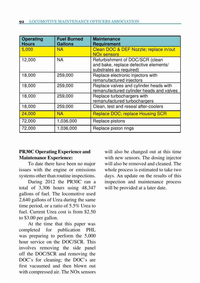
7/25/2019 Lmoa2013 Book Web Final
http://slidepdf.com/reader/full/lmoa2013-book-web-final 94/252
92 LOCOMOTIVE MAINTENANCE OFFICERS ASSOCIATION
OperatingHours
Fuel BurnedGallons
MaintenanceRequirement
5,000 NA Clean DOC & DEF Nozzle; replace in/outNOx sensors
12,000 NA Refurbishment of DOC/SCR (cleanand bake, replace defective elements/ substrates as required)
18,000 259,000 Replace electronic injectors withremanufactured injectors
18,000 259,000 Replace valves and cylinder heads withremanufactured cylinder heads and valves
18,000 259,000 Replace turbochargers withremanufactured turbochargers
18,000 259,000 Clean, test and reseal after-coolers
24,000 NA Replace DOC; replace Housing SCR
72,000 1,036,000 Replace pistons
72,000 1,036,000 Replace piston rings
PR30C Operating Experience and
Maintenance Experience:
To date there have been no major
issues with the engine or emissions
systems other than routine inspections.
During 2012 the PR30C ran a
total of 3,306 hours using 48,347
gallons of fuel. The locomotive used
2,640 gallons of Urea during the sametime period, or a ratio of 5.5% Urea to
fuel. Current Urea cost is from $2.50
to $3.00 per gallon.
At the time that this paper was
completed for publication PHL
was preparing to perform the 5,000
hour service on the DOC/SCR. This
involves removing the side paneloff the DOC/SCR and removing the
DOC’s for cleaning; the DOC’s are
rst vacuumed and then blown out
with compressed air. The NOx sensors
will also be changed out at this time
with new sensors. The dosing injector
will also be removed and cleaned. The
whole process is estimated to take two
days. An update on the results of this
inspection and maintenance process
will be provided at a later date.

7/25/2019 Lmoa2013 Book Web Final
http://slidepdf.com/reader/full/lmoa2013-book-web-final 95/252
Freight Car Parts Locomotive Parts
• Friction Castings (ASF & Barber)
• Control Springs (ASF & Barber)
• Column Wear Plates (ASF & Barber)
• Truck Side Frames
(70ton, 100ton, 125ton)
• Truck Bolsters
(70ton, 100ton, 125ton)
• Constant Contact Side Bearings
• Cast Draft Sills (Coal & Grain Cars)
• AAR D-Series Load Coils
• Low Profile Center Plates
• M901E/G Draft Gears
• Adapter Steering Pad Systems
(M976)
• Freight Car Axles
• Railway Wheels
• Tapered Roller Bearings• AAR Couplers
• AAR Yokes
• Knuckles
• Carrier Basket Springs
• New Cushioning Units
• Reconditioned Cushioning Units
• Braking Components
- Hand Brakes
- Slack Adjusters
- Empty/Load Devices
- Truck Mounted Brakes
- Brake Cylinders
- Truck Mounted Brake Rigging
• Wear Prevention Components
- Coupler Carriers and Wear Plates
- Brake Beam Guides
- Brake Rod and Bracket Protectors
- Center Bowl Wear Liner
- Center Bowl Horizontal Liners- Rear Yoke Support
• Locomotive Wheels
• Locomotive Roller Bearings
• Locomotive Springs
• New Locomotive Draft Gears
• Reconditioned Locomotive
Draft Gears
• Locomotive Axles
• GPS and condition-based tracking
and monitoring
IONX Asset Monitoring
VIRTUALLY
“EVERYTHING BUT THE BOXTM
”
© 2012 Amsted Rail Company, Inc.
Your single link to all undercarriage components for heavy haul service.
311 South Wacker | Suite 5300 | Chicago, IL 60606
(312) 922-4501 | AmstedRail.com
7/25/2019 Lmoa2013 Book Web Final
http://slidepdf.com/reader/full/lmoa2013-book-web-final 96/252
94 LOCOMOTIVE MAINTENANCE OFFICERS ASSOCIATION
As locomotive eets age, therecomes a point when an economic
decision needs to be made on
what to do with a unit that has
reached a point in its life where in
kind overhaul costs outweigh the
benets. To further complicate these
decisions are emission rules, new
technology, and lack of new 4-axlereplacement power. An option of
breathing new life into these units
is to “repower” them with the latest
engine technology to achieve various
goals of the investment such as fuel
savings, emissions reduction, lower
maintenance cost, etc.
Repower can be dened asreplacement of an existing engine
with an engine or engines of a
different conguration that may
include new technology, increase
or decrease in horsepower, change
in the number of cylinders, change
in fuel delivery system, or major
modications to meet more stringent
emission levels. The term repower
may also be used generically
to include other locomotive
improvements besides the engine
such as the control system, alternator,
cab, cooling, etc. The goal of this
paper is to educate the locomotive
community of repower options andwhat factors to consider to make the
most economical decisions.
What Drives Repowering
There are numerous reasons to
repower and all of them revolve around
economics; SAVING MONEY.
• Availability of certain types of loco-motives.
• Emissions requirements.
• Fuel economy.
• Maintenance.
• Locomotive eet consolidation.
• Productivity.
In today’s locomotive marketthere can be, in some instances, very
little choice for new replacement
locomotives unless one is looking
for high horsepower main line
locomotives. There are very few
choices when it comes to buying
new, lower horsepower four axle
locomotives and they are expensive.
An attractive alternative is to take
older four axle locomotives of
low to medium horsepower and
have them remanufactured. It
would only be logical to assess
repowering the remanufactured
locomotive with a new engine at the
Locomotive Repower: Why Repower
and What to Consider
Contributors:
Dennis Nott, Northwestern Consulting LL
Douglas Berry, MTU, Tognum America Inc
Mark Duve, Norfolk Southern Corporation
Timothy Standish, Electro Motive Diesel Inc

7/25/2019 Lmoa2013 Book Web Final
http://slidepdf.com/reader/full/lmoa2013-book-web-final 97/252
DIESEL MECHANICAL MAINTENANCE 95
time of remanufacture instead of
rebuilding the older engine in-kind.
The incremental increase cost ofthe new engine, with its likely life
cycle cost benets, may prove to
be more economically feasible than
rebuilding the older engine during the
remanufacture process.
Emissions are another reason
to repower older locomotives. As
a locomotive owner and operatorof a railroad there reasons to be a
responsible “green” citizen within
the community. In addition, if
the operation is located within an
emissions non-attainment area there
is likely to be funding from some
local, state or federal sources to
help defer the cost of the repower. Asection later in this paper will cover
emissions in more detail.
Fuel economy is an important
factor when making repower
decisions. New engine designs have
evolved, primarily due to emissions
requirements, where they are much
more efcient than the older engines
they replace. For example, in the case
of the replacement of an older EMD
engine with a new EMD engine you
will nd that the new engine will
produce the same horsepower with
fewer, more efcient, cylinders with
signicantly lower fuel consumption.
If you replace the older engine with
one of the new 4-cycle engine designsyou will nd that the inherent fuel
savings of the 4-cycle engine coupled
with the design efciencies that have
occurred during the emissions era
will produce signicant fuel savings.
The amount of fuel reduction will
depend on the fuel efciency of the
engine being replaced versus the fuel
efciency of the new engine and canrange from 15% to 25%. In life cycle
cost analysis of the older locomotive
versus the repowered locomotive, the
fuel savings will be the largest cost
factor and will often justify the cost to
do the repower.
Maintenance of the old
locomotive engine is another factorthat often can justify repowering
the locomotive. The old locomotive
engine is probably not as reliable as
desired with a high out of service
ratio, frequent road failures, leaks
or consumes copious amount of oil,
and may even require parts that are
harder and harder to nd. Repoweringwith a new engine will eliminate all
the undesirable reliability issues and
maintenance aspects of the older
engine for a signicant period of time.
If repowering is done on a eet basis,
the increased reliability and reduced
maintenance requirements may lead to
fewer locomotives being needed. Life
cycle maintenance cost analysis should
be performed to determine the actual
maintenance cost savings.
If the railroad operates
several different models or type of
locomotives it is often possible to
repower all the different models
or types of locomotives with the
same new engine repower package.Consolidation to one type of engine
will reduce parts inventories and
increase maintenance efciency.
Productivity gains can be
achieved by multiple avenues with
a repower on a eet basis. Often

7/25/2019 Lmoa2013 Book Web Final
http://slidepdf.com/reader/full/lmoa2013-book-web-final 98/252
96 LOCOMOTIVE MAINTENANCE OFFICERS ASSOCIATION
the locomotives being repowered
can receive a new engine of higher
horsepower that ts in the samefootprint of the old engine. If the
railroad operation uses multiple units
on a train, the increased horsepower
may result in unit reduction and the
savings associated with using fewer
locomotives on a train or fewer
locomotives in the eet needed to
perform the service. Even if unitreduction is not achieved, the higher
horsepower will lead to increased
train speed that could lower crew
costs and improve customer service.
If the repower is coupled with a
complete locomotive remanufacture
that includes improved tractive effort
adhesion control unit, a reductionmay be achieved as a result of the
higher tractive effort. It is important
to include any productivity gains that
can be achieved with a repower into
any life cycle cost evaluation.
Engines
When repowering an older
locomotive the main part of the
repower is the replacement of the
original diesel engine with a newer
more modern engine that is more
efcient in terms of emissions, fuel
economy and performance. Typically
the older locomotives are powered
with medium speed diesels from
EMD, G.E. or Alco.Railroads today have options
as to what engines are available to
them when doing a repower. The
manufacturers that provide prime
movers today are the following:
• Caterpillar
• Cummins
• EMD• MTU
Each of the manufacturers
listed provide a varied list of
available models that range in power
from 700bhp to 3600bhp for the
typical switcher or road switcher
applications. There are higherhorsepower models available, but
typical repowers are in the range
mentioned above. Each of these
manufacturers can provide details on
the specic model required, which
would include the following:
• Emissions
• Fuel Consumption• Maintenance
• Performance Curves
• Specic Engine Installation Param-
eters
• Support Network
Depending on what the railroad
is looking for in terms of emissions
from the engine an aftertreatment
system may need to be installed in
the locomotive during repower. This
may entail a Diesel Particulate Filter
(DPF), Diesel Oxidation Catalyst
(DOC), a combination of both, a
Selective Catalytic Reduction (SCR)
system or all of the above. Each
engine manufacturer is responsibleto provide the aftertreatment system
needed when supplying a particular
level of emissions with an emission
certicate.
Depending on the engine
manufacturer chosen, there will be

7/25/2019 Lmoa2013 Book Web Final
http://slidepdf.com/reader/full/lmoa2013-book-web-final 99/252
DIESEL MECHANICAL MAINTENANCE 97
specic criteria that have to be met
with the installation to ensure that
the engine operates properly in therepowered locomotive. Cooling
systems will have to be upgraded in
most cases as newer engines require a
split circuit cooling system where the
aftercooling system is separate from
the jacket water system as part of the
emission reduction strategy. This will
entail new radiator cores as the newerlower emission engines generate
higher heat rejection to the cooling
systems. Depending on the size of the
engine, a new or revamped cooling
hood may be required.
Most of the new engines today
use High Pressure Common Rail fuel
injection. These systems require amuch higher level of fuel ltration
due to the close tolerance of the high-
pressure pumps and injectors used.
Filtration down to 5-10 Microns will
be needed. In addition the fuel tank
needs to be thoroughly cleaned out
of any debris or sludge. Depending
on the particular repower, the fuel
tank may require an upgrade to a new
crash worthy tank.
Each engine manufacturer
will have a suggested maintenance
program that will give the maximum
performance of the engine
components throughout the life of
the engine to overhaul. Depending
on the locomotive duty cycle andthe particular railroads maintenance
program, either a 92-day or 184-day
cycle can usually be attained. The
longer 184-day cycle may require
larger oil or fuel ltration to meet this
requirement.
Support networks for the engines
should also be looked at.
• Will the engine manufacturer trainthe railroad employees to do main-
tenance and normal repairs on the
engine?
• What is the availability of replace-
ment engines at time of rebuild?
• Is there a good network for replace-
ment parts and at times trained fac-
tory technicians?
All of the above needs to be
looked in the decision making process
to ensure that the repower is a success
and the performance being sought is
attained.
AlternatorsThe repower will also require the
replacement of the traction alternator
if the new engine is a high-speed
(1800rpm) engine. There is a good
list of alternator manufacturers both
in the US as well as Europe that
make high-speed alternators. If the
repower is replacing an older EMD
with a newer EMD engine then the
existing medium speed alternator
or DC generator can either be re-
used, rebuilt or replaced with a new
or upgraded unit. Manufacturers of
alternators for the rail industry are:
• Baylor (national Oil Well)
• EMD
• GE• Hitzinger
• Kato
• Lechmotoren
• Marathon
• Newage

7/25/2019 Lmoa2013 Book Web Final
http://slidepdf.com/reader/full/lmoa2013-book-web-final 100/252
98 LOCOMOTIVE MAINTENANCE OFFICERS ASSOCIATION
All of these manufacturers
produce quality products. Make
sure that the performance of thealternator meets the requirements of
the particular locomotive in regards to
voltage and amperage. Depending on
the amount of amperage it will have
to produce will determine the size
of the rotor in the alternator. Engine
manufacturers will have a maximum
rear bearing load that has to beadhered to. If this is exceeded then
a two bearing alternator will have
to be specied. When this happens
the coupling between the engine and
alternator will change from a simple
ex plate to a more sophisticated
torsional coupling.
Torsional Couplings
As mentioned above, when a
torsional coupling has to be used,
then a torsional vibration analysis
should be calculated by the engine
manufacturer. There are various
coupling manufacturers who offer
variations of rubber couplings to
steel spring type couplings. Rubber
couplings will either be a bonded
rubber coupling that operates
in shear mode or a non-bonded
rubber coupling that operates
in compression. When rubber
couplings are used whether in shear
or compression, it is important to
take into consideration the operatingtemperature they will be subjected to
in order to select the proper type of
rubber or in some cases silicone in
order to get maximum life out of the
coupling.Steel spring couplings use
either encapsulated oil or oil from
the engine lubrication system for
their damping effect. These types of
couplings are not as heat sensitive asrubber, but require proper analysis in
order to determine the proper sizing
of the springs. Steel spring couplings
can go to engine overhaul and are
rebuildable at that time.
Auxiliary Drives
When doing a repower, there willbe specic auxiliary drives that will
have to be either renewed, replaced
or added. This could range from an
air compressor, auxiliary generator,
traction motor blower, or other drives
specic to a certain locomotive
installation.
Depending on the engineinstalled and the various drives that
are required, a torsional analysis may
be needed and needs to include the
driven components whether they are
driven from the front of the engine
crankshaft or from an auxiliary
PTO. In some cases, replacing an
electric driven air compressor with
a mechanically driven compressor
off the engine is a better or more
economical solution. All of these
possible options need to be taken into
consideration and discussed with the
contractor doing the repower.
Control Systems and Other Options
When repowering a locomotivethere are several choices or options
that can be made to improve the
locomotive. All of these choices or
options will increase the initial cost
of the repower but through operating
or maintenance cost savings can be

7/25/2019 Lmoa2013 Book Web Final
http://slidepdf.com/reader/full/lmoa2013-book-web-final 101/252
Bearing Industry Standards Since 1885 A t Magnus, we neverquit. Bearings have beenour obsession since 1885
– and it shows.
We continually set newstandards for the bearing
industry with new
patents, specializedcasting and machiningmethods. As a result,
you can expect nothingless than innovative
engineering with everybearing we cast.
It’s why we’re recognizedas the industry leader and
premier global supplierof solid bearings.
To contact one of our dedicated,
knowledgeable professionals,
call (402) 721-9540.
Magnus Farley Inc. n P.O. Box 1029 Fremont, Nebraska 68026 n www.magnus-farley.com

7/25/2019 Lmoa2013 Book Web Final
http://slidepdf.com/reader/full/lmoa2013-book-web-final 102/252
100 LOCOMOTIVE MAINTENANCE OFFICERS ASSOCIATION
justied with an accurate life cycle
cost analysis. Choices or options that
are often considered during a repowerare:
• Traction Control Systems
• Automatic Engine Start/Stop
(AESS)
• Auxiliary Power Units (APU’s) or
Shore Power
• Remanufacture of other compo-
nents or systems
Traction Control Systems
Traction control systems
are often added at the time the
locomotive is repowered to improve
adhesion that reduces wheel slip
issues and increases the tractive
effort making the locomotive moreproductive. These systems vary
from add on electronics that only
improve adhesion to a full blown
microprocessors that control other
systems. Traction control systems
can be purchased from the OEM
locomotive builders as well as several
aftermarket manufacturers.
Obviously the systems that only
control adhesion will be the less
costly and are the easiest to install
as they require the least rewiring.
These systems can be added to the
locomotive repower in the range of
$25,000 to $30,000 per locomotive
installed.
The more complexmicroprocessor systems control
more functions than the adhesion
system such as fan control, alternator
control, auxiliary generator control,
air compressor control and dynamic
braking, and in some cases engine
control. They will also provide a way
to interface with these controls and
systems to provide alarms and capturefaults and other troubleshooting
information. One major advantage is
that most of the relays and/or circuit
board technology in the electrical
cabinet will be replaced by the
microprocessor system leading to
better reliability.
If repowering with an enginefrom one of the OEM locomotive
builders, the microprocessor will
usually control the engine functions
as well as traction control and other
systems control.
If repowering with an engine from
one of the OEM engine builders, they
will provide their own engine controlmicroprocessor with the engine but this
may not or may not necessarily provide
traction control. With an engine from
an OEM engine builder an aftermarket
microprocessor will interface to provide
engine throttle control; however, some
of the aftermarket microprocessors
can be adapted to receive information
from the OEM engine control system
and display it on the aftermarket
microprocessor interface screen. It is
recommended that each manufacturer
of aftermarket and locomotive OEM
microprocessor systems be consulted to
determine what each of their products
will provide over and above the
traction control and decide what ts thelocomotive being repowered best.
The full microprocessor control
system also requires a more costly
installation process as it requires
removal and replacement of most
of the old relay logic and/or circuit

7/25/2019 Lmoa2013 Book Web Final
http://slidepdf.com/reader/full/lmoa2013-book-web-final 103/252
DIESEL MECHANICAL MAINTENANCE 101
board technology and wiring.
Depending on the degree of control
chosen, there may be a requirementto install current measuring devices
and sensors on the operating systems
on the locomotive. Keep in mind
that any traction control system will
also require some method of speed
control measurement system such
as axle alternators, traction motor
speed probes or radar. Cost for thefull microprocessor control system
can vary from $50,000 to $100,000
depending on what system control
functions and engine interface are
required or chosen.
Automatic Engine Start/Stop
Automatic Engine Start/Stop willbe an option unless the locomotive
being repowered falls into an
Environmental Protection Agency
(EPA) category where the age of the
locomotive and the EPA emissions
tier level mandates the installation of
AESS (See Section on Emissions).
AESS is basically an add on
system that allows the locomotive
engine to shut down from idle under
certain parameters when not needed
to conserve fuel, reduce emissions,
reduce lube oil consumption and
reduce wear and tear on the engine.
If the parameters such as main
reservoir air pressure, battery
voltage, ambient temperature, orengine water temperature are within
acceptable levels the engine can shut
down. When any of the parameters
drop below the acceptable level the
engine will restart and run until the
parameter(s) are restored, then shut
down again. AESS also keeps the
locomotive in a state of readiness; it
is always warmed up and ready to go.Some AESS systems can also
provide other functions such as load
shedding to better protect the battery
charging and reduce the number of
starts/stops or control over APU’s.
Adding AESS to the repower can
bring more fuel savings to the bottom
line; particularly for operations incolder climates.
Auxiliary Power Units (APU’s) or
Shore Power
Auxiliary Power Units (APU’s)
or Shore Power are two add on
systems that that can work with an
AESS system or by themselves.APU’s and Shore Power are basically
ways to protect the engine and
batteries, save fuel, and reduce
emissions when the locomotive is
not being used and the engine is not
running during cold weather. Both
systems usually include on-board
pumps that heat and circulate engine
cooling water and a system to provide
battery charging; the difference is the
power source for each method.
APU’s have their own small
diesel engine that operate at a fuel
consumption rate that is signicantly
less than that of an idling locomotive
engine. The small diesel engine runs the
equipment that heats and recirculatesthe engine cooling water throughout
the locomotive wherever the cooling
water circulates. In addition, the APU
provides the battery charging to keep
the batteries fully charged while the
engine is not running.

7/25/2019 Lmoa2013 Book Web Final
http://slidepdf.com/reader/full/lmoa2013-book-web-final 104/252
102 LOCOMOTIVE MAINTENANCE OFFICERS ASSOCIATION
Shore Power has the same
onboard features and functions as the
APU but instead of being powered bya small diesel engine the equipment
is powered by electricity provided
from a wayside power source like
those used by boats and ships (hence
the term “Shore Power”). The main
drawback to shore power is that
wayside infrastructure for the power
source is required wherever thelocomotive is parked.
Remanufacture of Other
Components or Systems
When a locomotive is repowered
it also an excellent time to totally
remanufacture and/or upgrade the rest
of the locomotive. One way to lookat is that the new engine now has a
typical life of 15 to 20 years and the
rest of the locomotive may be worn
out; while reliability of the engine has
increased the rest of the locomotive
may be a basket case.
Cost to rebuild or remanufacture
can double or triple the cost of the
repower but essentially the whole
locomotive will be “New” at the end
of the process. Due diligence during
the life cycle cost analysis will dictate
whether or not a total remanufacture is
cost effective.
Emissions Regulations for RepowersRepowering a locomotive
does not necessarily mean the
locomotive now meets emissions
requirements for new locomotives.
The emissions regulations that
apply to the repowered locomotive
depends upon the amount of used
verses new components and the year
of the repower. EPA regulationspertaining to repowers are found
in 40CFR1033.640. Table XX is a
summary of 40CFR1033.640, but
the table does not include every
detail. It is strongly suggested that
each railroad or locomotive rebuilder
review the regulations with its legal
counsel once the work scope for arepower is done and the amount of
new components are determined.
Potentials for Government Funding
Since low horsepower
locomotives are used in low mileage,
low duty cycle yard and local service,
the fuel savings and maintenancesavings may not be enough to justify
the cost of repowering a locomotive.
In certain cities or highly populated
counties, there might be a source of
funding through government grants.
The EPA has established National
Ambient Air Quality Standards
(NAAQS) that sets the limits on
pollutants such as carbon dioxide,
lead, nitrogen dioxide, ozone,
particulate matter (PM-10 and PM-
2.5) and sulfur dioxide. Generally
areas of large populations or areas
where there is a large concentration
of industries such as paper mills
or power plants do not meet the
NAAQS standards. Those areas thatdon’t meet the NAAQS standards
are known as non-attainment zones.
(See the following table for Non-
Attainment counties.) In most states,
there are public funding opportunities
through either the Diesel Emissions

7/25/2019 Lmoa2013 Book Web Final
http://slidepdf.com/reader/full/lmoa2013-book-web-final 105/252
DIESEL MECHANICAL MAINTENANCE 103
% Used Parts* <25% >=25% AND <50% >50%
EPA Terminology Freshly Manufac-tured
Remanufactured“AND” Refurbished
Remanufactured
Regulations The manufacturedate is changed tothe day when the re-manufacture is com-pleted, which is theNEW manufacturedate. All emissionsregulations cor-responding to NEWlocomotives on theNEW manufacturedate are applicable.
Switch Locomotives:• Before 1/1/15 Tier
0 locos must meetTier 0 Switch andLine Haul Stan-dards.
• After 1/1/15 Tier3 and all otherswitch locos mustmeet Tier 3 SwitchStandards
Line Haul:• 3000 HP must meet
Freshly Manu-factured (NEW)
standards fordate of completedrefurbishment.
• Before1/1/15<3000 HP,Tier 0 locos mustmeet Tier 0 Switchand Line HaulStandards. After1/1/15 NEW loco
emissions stan-dards. Generationof emissions cred-its is prohibited.
The original dateof locomotive is re-tained. All regulationsthat are applicable tothe original date oflocomotive manufac-ture are in effect.
Additional Labeling Secondary locomo-tive label requiredstating the locomo-tive is refurbishedand certied EPA tier
Secondary locomo-tive label requiredstating the locomo-tive is refurbishedand certied EPA tier.
None
TABLE XX40CFR1033.640 PROVISIONS FOR REPOWERED AND REFURBISHED
LOCOMOTIVES

7/25/2019 Lmoa2013 Book Web Final
http://slidepdf.com/reader/full/lmoa2013-book-web-final 106/252
104 LOCOMOTIVE MAINTENANCE OFFICERS ASSOCIATION
Reduction Act (DERA) Grant
program or the Congestion Mitigation
and Air Quality Program (CMAQ)that provide grants to repower
locomotives. Generally, these grants
are awarded through either local
Metropolitan Planning Authorities
or through the state environmental
protection agency. Each planning
authority or state EPA sets their own
individual guidelines and policies forgrant awards depending upon the type
and amount of emissions reductions.
Most emissions reductions grants for
locomotives target nitrogen oxides
and particulate matter.
A majority of the locomotive
grants are through the CMAQ
program. The goal of the grant isto provide subsidies such that the
locomotive owner will reduce the
amount of emissions to a level that is
below the emissions regulations. For
instance, a CMAQ grant can be used
to repower a locomotive to Tier 3,
which by law would only be required
to meet Tier 0+. Most grants cover
70 to 80 percent of the repower costs,
with the locomotive owner matching
the rest. However, there are many
conditions attached to the grants
which may not be palatable to most
railroads.
The CMAQ grant funding
usually has several stipulations
such as the locomotives fundedmust stay in Non-Attainment zone
for a minimal amount of time,
usually around 80% for ve to ten
years, which reduces operations
exibility. In addition, there are
certain certications that a grant
award must comply. There are also
reporting requirements in which the
grant recipient must report on thelocomotive hours of operation, fuel
used, and estimated emissions. In
additions, since the CMAQ funding
comes from the US Department
of Transportation to the Federal
Highway Administration, it is subject
to all the rules and regulations
governing the FHWA. One of thestrictest rules is the Buy America
regulations.
The Buy America Regulations
for FHWA are governed under 23
CFR 635.410 which states that no
more that 0.1% of non US steel or
iron can be used in a project. Further,
clarication from FHWA memoshas revealed that a major iron or
steel component is a component that
is 90% or more iron or steel. Since
we now live a global economy it
is difcult to nd an engine that
meets the FHWA’s stringent Buy
America Requirements. In fact, there
is no known engine that meets these
requirements. Therefore, to apply for
a one of these grants, a railroad must
expect to work with the local agency
providing the grant in obtaining a
Buy America Waiver.
In pursuing government funding,
one must be very patient as it may
take a year or more to get awarded a
grant and sometimes a year or moreto work through the contract stage.
As in the emissions regulations,
it is suggested that legal counsel
be consulted in regards to public
funding.

7/25/2019 Lmoa2013 Book Web Final
http://slidepdf.com/reader/full/lmoa2013-book-web-final 107/252
DIESEL MECHANICAL MAINTENANCE 105
Counties Designated Nonattainment
for Clean A1r Act's NatiOnalAmbient Alr Qualey Standards (NAAOS) •
L...--.--./ -
County Destgnated
Nonana1nment
for 6 NMOS POllutants
County Designated
Nonatta1nment
for 5 NAAQS POllutants
County Destgnated
Nonatta1nment
for 4 NAAQS POllutants
County Destgnated
Nonatta1nment
for 3 NAAQS POllutants
County Destgnated Nonatta1nment for 2 NAAOS POllutants
County Destgnated Nonatta1nment for 1 NAAQS POllutant
Guam • P1t1
and
Tangu 1sson Count1es are destgnated nonatta1nment for th S 2 NAAOS
· The Nabonal
Amb
1ent
A1r
Quality Standards (NAAOS) are
heahh
standards for Carbon Monoxide.
Lead (1978 and 2008) Nitrogen
DIOXIde
, 8-hourOzone (1997
and
2006),
PartiCUlate
Maner (PM-10
and
PM
-2 5 (
1997
and 2006))
and
Sulfur
DIOxid
e
•• Included
n
the counts are counties
deSignated
f
or
NAAOS and
rev1se
d NAAOS po l utants
1
h
our Ozone IS excluded Partial count1es those wlh
part
of the county deSignated nonattainment
and part attatnment, are shown as full counttes
on
the map
The IllinOIS porbon of the St Lou1s, MO -IL 8-hr Ozone muh
1 s
tate
nonatta1nmen
t area has been
redestgnated but the area Is noc considered a matntenance area unt l both Slates n the area
are redeSignated All the counties for th sarea are displayed as betng n nonattatnment
7/25/2019 Lmoa2013 Book Web Final
http://slidepdf.com/reader/full/lmoa2013-book-web-final 108/252
106 LOCOMOTIVE MAINTENANCE OFFICERS ASSOCIATION
What to Repower
In theory, any older locomotive
can be repowered; some are just betterthan others.
Here are some questions that need
to be asked regarding the existing
candidate for repowering:
• Is the existing locomotive doing the
job?
• Too light; not enough tractive ef-
fort? • Too long; won’t couple on sharp
curves or rolls rail over?
• Not enough HP; won’t make track
speed with tonnage?
• What is the condition of the existing
locomotive?
• Frame in good shape?
• Cab and car body in good shape? • Are the other systems on the lo-
comotive not being replaced as a
result of the repower in good con-
dition?
• Are parts available for the next 15 or
20 years for the portion of the loco-
motive not repowered?
If there are no issues with the
above questions then the locomotive
could be a candidate for repowering;
however, more due diligence is
required to determine what repower
engine package the locomotive could
be repowered with.
When investigating what engines
are available probably one of the mostimportant aspects one must keep in
mind is that the main generator or
alternator must be matched to the
engine of choice. If the locomotive
is one that has been manufactured
by one of the locomotive OEM’s and
the repower engine is coming from
the same builder the existing main
generator or alternator will in alllikelihood match the RPM of the new
engine. This makes the repower much
simpler as the new repower engine
will probably be the same physical
size or smaller than the engine
removed. It should be mentioned that
one OEM engine builder does offer
a gear reduction package to drive anEMD alternator but it will add length
to the engine/alternator package in the
locomotive.
If the repower engine of choice
is from one of the OEM engine
builders it will in all likelihood run at
a maximum RPM of 1,800 RPM and
a new main alternator will be required(except as noted above). The 1,800
RPM alternators are typically longer
than existing locomotive OEM main
generators and main alternators but
the engines are typically smaller than
the engines removed.
Also, most engines and alternator
packages using the OEM engine
builder’s products have the engine and
main alternator mounted on an isolated
skid and the skid is mounted to the
locomotive frame. The traction motor
blower is also generally mounted to
the front of the skid and driven though
by the engine crankshaft through the
main alternator. The overall length
of the new engine/main alternator/ blower skid package can be longer
than the engine/main generator or
main alternator package removed. The
main consideration is that after the old
engine and alternator is removed there
is adequate room to install the new

7/25/2019 Lmoa2013 Book Web Final
http://slidepdf.com/reader/full/lmoa2013-book-web-final 109/252
DIESEL MECHANICAL MAINTENANCE 107
engine/alternator/blower skid package
in the area where the old engine was
removed.Another consideration will be the
engine cooling package. Is the existing
cooling system adequate for the new
repower engine? As new engines have
been developed to meet emissions
requirements the need for more
cooling capacity has arisen. This can
be in the form of more engine jacketwater cooling or the requirement to
provide additional cooling for after-
coolers with split cooling systems. In
some cases the increase in the size of
the radiators has also driven the need
for additional cooling fans. The issue
to be aware of here is that the repower
engine choice will require adequatecooling and there may be a need for
additional room on the locomotive
to provide additional radiator or fan
capacity.
The choice of the repower engine
will also drive how the locomotive
receives its companion alternator
power, the auxiliary generator and air
compressor power. Again these issues
are more easily addressed if the new
repower engine is provided by the
OEM locomotive builder that built the
locomotive originally.
If an engine from one of the
OEM engine builders is chosen then
consideration must be made for how
the companion, auxiliary generatorand air compressor are driven. In most
cases the companion alternator can be
combined with the main alternator at
the expense of making a longer skid
package. The auxiliary generator can
be driven off an engine PTO if the
engine accessory drive can be geared
to operate at the proper RPM or it
can be shaft driven off the crankshaft.If driven off the engine crankshaft
it would be recommended that the
auxiliary generator be of the 18kW
AC type known as a “Super Aux”
so that it will operate properly at the
600 RPM idle rating of most OEM
engine manufacture’s engines. Air
compressors will probably be requiredto be electric motor driven.
In conclusion, there are several
issues that need to be considered
when deciding to repower an existing
locomotive and all are space/
packaging driven. It will probably be
easier to repower EMD GP and SD
type locomotives or GE U or dash7 locomotives as there is usually
adequate room to make choices.
Switchers will probably be more
difcult to repower especially the
older EMD SW series; the EMD MP
series will be less difcult to repower.
Current Experience
There have been approximately
475 “repowers” to date of which
around 350 would fall into the
multiple engine genset category and
the rest (125) into the single engine
repower category. Experience and
reasoning for repowers vary by
railroad. Emission reductions and
grant funding drove early adoptionof genset locomotives. Recent engine
and emissions technology gains for
larger diesel engines have closed
that gap. The type of service that the
repowered locomotive is used in also
contributes to its success and certain

7/25/2019 Lmoa2013 Book Web Final
http://slidepdf.com/reader/full/lmoa2013-book-web-final 110/252
108 LOCOMOTIVE MAINTENANCE OFFICERS ASSOCIATION
models may nd a better niche than
others for example is it for yard work
or for road switching?As stated in the beginning, there
are many reasons for repowering
and often have one main driving
factor with other minor factors.
For example, one railroad’s main
factor was fuel efciency along
with simplicity of maintenance.
Fuel efciency was the same withanother railroad along with eet
standardization. Yet another railroad’s
decision was to just rebuild in kind
based on some repower experience
and cost models, especially if no
funding is available. Another railroad
found that improvements have been
made in the latest gensets since
original introduction but do take more
skill in to troubleshoot or repair.
Conclusion
There are many factors to
consider when deciding on whether
or not to repower locomotives and
unfortunately no simple answers. This
hopefully gives a good basis to start
the analysis. Each railroad will haveto assign weighting factors to the
importance of each of the items along
with associated costs and decide
what repower decision is the most
economical.

7/25/2019 Lmoa2013 Book Web Final
http://slidepdf.com/reader/full/lmoa2013-book-web-final 111/252
Discover
The Locomotive ngine
· a a i l J ~ f t
~ ~ ~ ~ l f t i ~ l i ~ f
Railways worldwide are
, I J, : ,
l l l f l f l t
using MIBA Bearings In
their EMD, G.E. and ALCO Engines. They depend
on
MIBA for
continuous research and development and for MIB 's
manufacturing quality assurance systems to provide the added
service life that the railways want for their engines.
C LL
OR
F X YOUR REQUIREMENTS TO US
TODAY
Ultimate
Performance
and
Durability
Miba
Bearings
U.S.
5037 N. State
Rt.
60
McConnelsvill
e, Ohio
43756
AAR Quality Assurance Certif ication
M 1003
7 40)
962-4242
FAX 7
40) 962-8202
7/25/2019 Lmoa2013 Book Web Final
http://slidepdf.com/reader/full/lmoa2013-book-web-final 112/252
110 LOCOMOTIVE MAINTENANCE OFFICERS ASSOCIATION
Introduction
The use of polymer material as a
replacement for hardened steel, brass,
and other bearing materials, has in-
creased over the past several years
and its use has yielded very positive
and successful results. Our goal inthis paper is to summarize the benets
and provide clarication on the use of
nylon-plastic bushings as a benecial
replacement to steel when applied to
locomotive brake rigging and related
wear components.
The material used is basically ny-
lon and the accepted supplier is a com-pany specializing in the manufacture of
polymer components. Other polymers
could be used but there are a vast num-
ber available with varying properties.
Careful selection and testing of alterna-
tives is required if problems are to be
avoided.
Polymer Bushings in Rail
Applications
1) Design and Benets
2) Fitting Practice
3) Test Data
4) Transit and Light Rail Applica-
tions
5) Passenger Service Applications
6) Locomotive Applications
7) FAQ’s
Design
When designing a polymer com-
ponent for replacing traditional ma-terials, an established procedure is
observed that takes into account the
following considerations:
1) The housing and pin size – The run-
ning clearances are calculated using
this data.
2) Load capability of the material –
The working loads are calculated foreach application.
3) Proximity to a heat source – The
maximum operating temperature of
the polymer is not exceeded even in
extreme conditions.
4) Moisture absorption – The maxi-
mum growth dimensions of the
polymer do not impede the running
clearances for the design under all
possible in-service moisture condi-
tions.
5) Fire performance – The ability of
the material to self extinguish and
not emit toxic fumes.
6) Environment – The in-service con-
21st Century Locomotive Truck and Bogie
Related Improvements
Presented by:
Tom Casper
Vice President of Sales and Marketing, Hadady Corporation
&
Casey Shepherd
Chief Mechanical Ofcer, Arkansas & Missouri Railroad

7/25/2019 Lmoa2013 Book Web Final
http://slidepdf.com/reader/full/lmoa2013-book-web-final 113/252
DIESEL MECHANICAL MAINTENANCE 111
ditions to be assessed, including the
possible interference of adjacent
mechanisms.
Benets
1) Reduction in wear resulting in in-
creased performance by up to 5
times when compared to steel bush-
ings.
2) Longer life for bushings and pins
coupled with consistent friction,stiffness, and wear characteristics.
3) No alignment difculties when as-
sembling.
4) Improved likelihood of housing rec-
lamation.
5) Quick and easy application and re-
moval.
6) Lower material costs.7) System wide reduction and potential
elimination of brake head and slack
adjuster seizures.
Fitting Practice
The following is a list of important
requirements during the tting of poly-
mer material:
1) The tolerance limits on the housing
and pins are in most cases no differ-
ent to the previous limits. However,
it is important that they are adhered
to. Gauges are recommended in all
cases to insure all housing and pin
dimensions are within the tolerance
band stated on the relevant drawing.2) Before tting polymer bushings, the
housing and pins should be clean
and free of grease, corrosion depos-
its, paint, burrs, and debris.
3) The use of excessive force to install
the polymer bushing is not required.
Excessive force usually indicates a
problem. Bushings should be in-
stalled using a soft-faced mallet anda block of wood. Note: Use of a
steel hammer is not permitted.
4) Once the bushing is tted into the
housing, inspect to insure the bush-
ing cannot be moved by hand. If
the bushing can be moved by hand,
remove and re-check the housing di-
ameter.5) After tting the pin, inspect for suf -
cient clearance to enable free rota-
tion. No binding or tight spots are
permitted.
6) The polymer is not as tolerant to
heat as steel and care should be used
particularly if welding in close prox-
imity to the material.7) The polymer has the advantage of
different color options. In general,
yellow has been used for standard
size components and blue for over-
size. There is no difference in the
performance between the two mate-
rials since they are exactly the same
grade.
8) The material used is compatible
with most grades of lubrication. In
some applications, lubrication is
recommended at the overhaul stage
while in others it is not required.
Reference should be made to the
overhaul procedures.

7/25/2019 Lmoa2013 Book Web Final
http://slidepdf.com/reader/full/lmoa2013-book-web-final 114/252
112 LOCOMOTIVE MAINTENANCE OFFICERS ASSOCIATION
BNSF Test Results on SD70MAC Locomotive Trucks, (1,000,000 Miles inService at Inspection)
Qty Loc Bushing Bush ID Pin Pin Pin
Bushing Item # I.D. NEW AtInspection
3 year test
Dia. NEW Dia. min Dia. max
8032159 (24) 1 1.127/1.125 1.150 1.111/1.107Slack Adj 2 1.169 1.045 1.045
3 1.147 1.03 1.03
4 1.142
8052334 8 1.127/1.125 1.111/1.107 Not Measured
HB 2 1.125
LL
8052336 16 1.252/1.250 1.236/1.232 Not Measured
HB 2 1.265
8059991 4 1.377/1.375 1.361/1.357
LD 3 1.374 1.36 1.359
8065520 13 1.127/1.125 1.111/1.107 Not Measured
HB 5 1.128
LL 4 1.152
LD 4 1.144
8147661 1 1.502/1.50 1.486/1.482 Not Measured
HB 3 1.513
8197960 4 1.252/1.250 1.235/1.231
LD 1/2 2 1.258 1.2335 1.232
LD 2/2 2 1.259
8336929 16 1.377/1.375 1.361/1.357 Not Measured
Hanger 1/2 3 1.390
Hanger 2/2 3 1.392
40023405 16 1.817/1.814 1.800/1.796
Hanger 1/2 2 1.824 1.796 1.797
Hanger 2/2 2 1.825
40026004 8 1.817/1.814 1.800/1.796
LL 3 1.880 1.7955 1.1745
Brake Head Assembly Pin with 1,000,000Brake Head Assembly Pin with 1,000,000
miles of service (SD70)MACmiles of service (SD70)MAC

7/25/2019 Lmoa2013 Book Web Final
http://slidepdf.com/reader/full/lmoa2013-book-web-final 115/252
DIESEL MECHANICAL MAINTENANCE 113
The test data above reects inspec-
tion measurements taken during disas-
sembly and re-assembly of SD 70 radi-al trucks in Alliance, NE. At teardown,
the trucks had nearly 1 million miles of
service since the initial plastic bushing
application. The data and measure-
ments taken are consistent with other
tests…virtually no wear on the pins
and bushings. The minimal wear con-
ditions will result in longer life and lessmaintenance between brake rigging
overhauls.
Canadian Pacifc Railway Test Data on GP Locomotives with Clasp Brakes
Push RodPush Rod

7/25/2019 Lmoa2013 Book Web Final
http://slidepdf.com/reader/full/lmoa2013-book-web-final 116/252
114 LOCOMOTIVE MAINTENANCE OFFICERS ASSOCIATION
Unit # CP3071 Mileage from Dec 1997 to Dec. 2000 for Polymer Bushing Test 72,746 Miles
NOMINAL BUSHING
SIZES
C B T R E F #
G M
P A R T #
C A R
C A R S
T Y P E
B U S H
I D
B U S H
O D
B U S H
L E N G T H
H O U S I N G
D I M E N S
P I N D I A M
DESCRIPTION
695 8160207 4 16 A 1.750 2.115 1.000 2.110 1.750 Outside BrakeLever
Measured 1.750 N/A N/A 2.097 1.750 Top Left Bush Measured 1.748 2.110 1.746
Measured 1.746 2.098 1.749
Measured 1.747Average 1.747 2.101 1.748
695 8160207 4 16 A 1.750 2.115 1.000 2.110 1.750 Outside BrakeLever
Measured 1.746 N/A N/A 2.100 1.746 Top Left Bush Measured 1.748 2.095 1.749
Measured 1.744Average 1.746 2.0975 1.748
695 8160207 4 16 A 1.750 2.115 1.000 2.110 1.750 Outside BrakeLever
Measured 1.749 N/A N/A to spec. 1.746 Top Right Bush Measured 1.751 1.753
Measured 1.752 1.749Measured 1.752Average 1.751 2.110 1.749
695 8160207 4 16 A 1.750 2.115 1.000 2.110 1.750 Outside BrakeLever
Measured 1.753 N/A N/A to spec. 1.746 Top Right Bush Measured 1.753 1.753
Measured 1.755 1.749Measured 1.755Average 1.754 2.110 1.749
696 8065516 4 16 A 1.750 2.115 2.000 2.110 1.750 Outside BrakeLever Measured 1.738 N/A N/A 2.100 N/A Centre Left Bush Measured 1.742 2.095
Measured 1.742Measured 1.740Average 1.741 2.098 1.750
696 8065516 4 16 A 1.750 2.115 2.000 2.110 1.750 Outside BrakeLever
Measured 1.739 N/A N/A 2.100 N/A Centre Left Bush Measured 1.739 2.095
MeasuredMeasured
Average 1.739 2.098 1.750
696 8065516 4 16 A 1.750 2.115 2.000 2.110 1.750 Outside BrakeLever
Measured 1.746 N/A N/A 2.100 N/A Centre RightBush
Measured 1.747 2.095Measured 1.746Measured 1.746Average 1.746 2.098 1.750
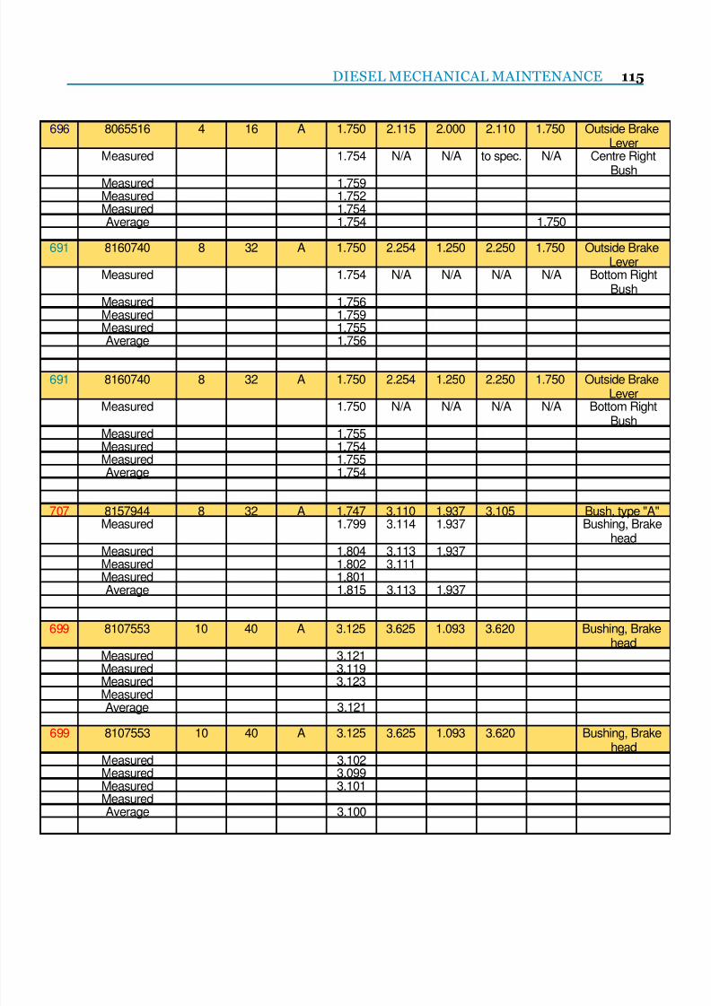
7/25/2019 Lmoa2013 Book Web Final
http://slidepdf.com/reader/full/lmoa2013-book-web-final 117/252
DIESEL MECHANICAL MAINTENANCE 115
696 8065516 4 16 A 1.750 2.115 2.000 2.110 1.750 Outside BrakeLever
Measured 1.754 N/A N/A to spec. N/A Centre Right
Bush Measured 1.759Measured 1.752Measured 1.754Average 1.754 1.750
691 8160740 8 32 A 1.750 2.254 1.250 2.250 1.750 Outside BrakeLever
Measured 1.754 N/A N/A N/A N/A Bottom RightBush
Measured 1.756Measured 1.759Measured 1.755Average 1.756
691 8160740 8 32 A 1.750 2.254 1.250 2.250 1.750 Outside BrakeLever
Measured 1.750 N/A N/A N/A N/A Bottom RightBush
Measured 1.755Measured 1.754Measured 1.755Average 1.754
707 8157944 8 32 A 1.747 3.110 1.937 3.105 Bush, type "A"
Measured 1.799 3.114 1.937 Bushing, Brakehead Measured 1.804 3.113 1.937
Measured 1.802 3.111Measured 1.801Average 1.815 3.113 1.937
699 8107553 10 40 A 3.125 3.625 1.093 3.620 Bushing, Brakehead
Measured 3.121Measured 3.119Measured 3.123MeasuredAverage 3.121
699 8107553 10 40 A 3.125 3.625 1.093 3.620 Bushing, Brakehead
Measured 3.102Measured 3.099Measured 3.101MeasuredAverage 3.100
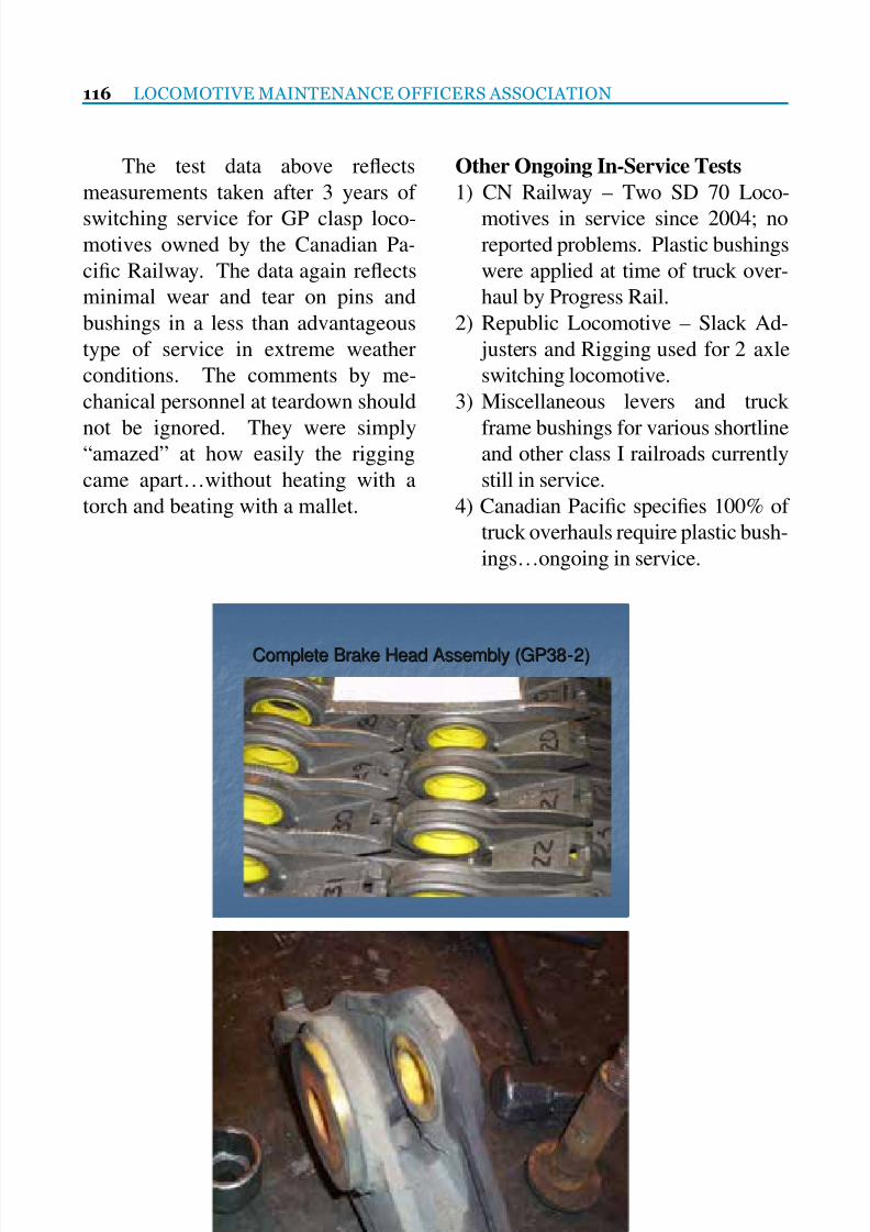
7/25/2019 Lmoa2013 Book Web Final
http://slidepdf.com/reader/full/lmoa2013-book-web-final 118/252
116 LOCOMOTIVE MAINTENANCE OFFICERS ASSOCIATION
The test data above reects
measurements taken after 3 years of
switching service for GP clasp loco-motives owned by the Canadian Pa-
cic Railway. The data again reects
minimal wear and tear on pins and
bushings in a less than advantageous
type of service in extreme weather
conditions. The comments by me-
chanical personnel at teardown should
not be ignored. They were simply“amazed” at how easily the rigging
came apart…without heating with a
torch and beating with a mallet.
Other Ongoing In-Service Tests
1) CN Railway – Two SD 70 Loco-
motives in service since 2004; noreported problems. Plastic bushings
were applied at time of truck over-
haul by Progress Rail.
2) Republic Locomotive – Slack Ad-
justers and Rigging used for 2 axle
switching locomotive.
3) Miscellaneous levers and truck
frame bushings for various shortlineand other class I railroads currently
still in service.
4) Canadian Pacic species 100% of
truck overhauls require plastic bush-
ings…ongoing in service.
Complete Brake Head Assembly (GP38Complete Brake Head Assembly (GP38--2)2)
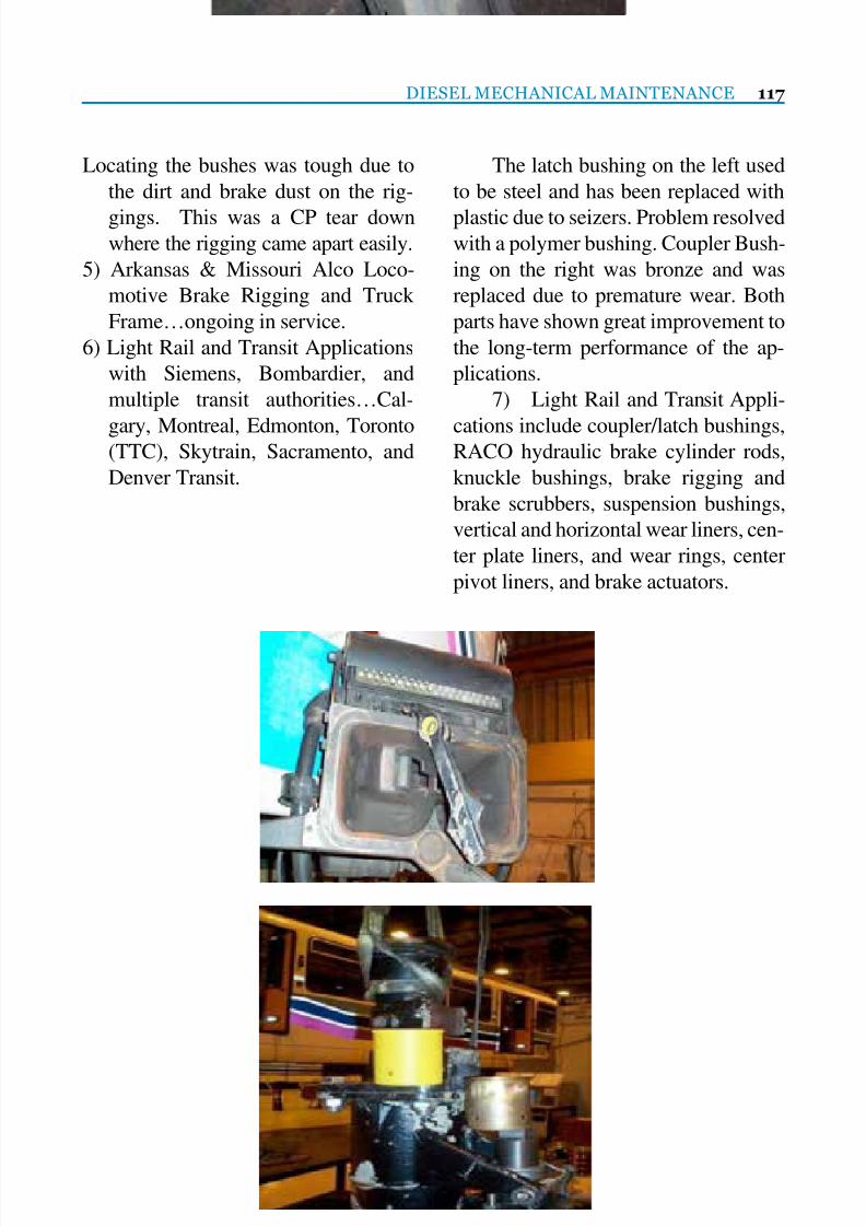
7/25/2019 Lmoa2013 Book Web Final
http://slidepdf.com/reader/full/lmoa2013-book-web-final 119/252
DIESEL MECHANICAL MAINTENANCE 117
Locating the bushes was tough due to
the dirt and brake dust on the rig-
gings. This was a CP tear downwhere the rigging came apart easily.
5) Arkansas & Missouri Alco Loco-
motive Brake Rigging and Truck
Frame…ongoing in service.
6) Light Rail and Transit Applications
with Siemens, Bombardier, and
multiple transit authorities…Cal-
gary, Montreal, Edmonton, Toronto(TTC), Skytrain, Sacramento, and
Denver Transit.
The latch bushing on the left used
to be steel and has been replaced with
plastic due to seizers. Problem resolvedwith a polymer bushing. Coupler Bush-
ing on the right was bronze and was
replaced due to premature wear. Both
parts have shown great improvement to
the long-term performance of the ap-
plications.
7) Light Rail and Transit Appli-
cations include coupler/latch bushings,RACO hydraulic brake cylinder rods,
knuckle bushings, brake rigging and
brake scrubbers, suspension bushings,
vertical and horizontal wear liners, cen-
ter plate liners, and wear rings, center
pivot liners, and brake actuators.

7/25/2019 Lmoa2013 Book Web Final
http://slidepdf.com/reader/full/lmoa2013-book-web-final 120/252
118 LOCOMOTIVE MAINTENANCE OFFICERS ASSOCIATION
Bottom Right picture shows the
location of the suspension bushings
used by Montreal Transit for the last 15years.
The other photos show different
hydraulic brake applications with Poly-
mer bushings installed.
Replaced bushing at the end of
the hydraulic cylinder with a Polymer
(Devlon A153/S) bushing. The existing
steel bushing was failing due to exces-sive vibration when the wheel scrubber
was activated. The new plastic bushing
eliminated the failure from vibration
due to the elastic nature of the bushing.

7/25/2019 Lmoa2013 Book Web Final
http://slidepdf.com/reader/full/lmoa2013-book-web-final 121/252
DIESEL MECHANICAL MAINTENANCE 119
8) All Light Rail Plastic Applica-
tions have been approved by the each
transit authority to replace the steel onsteel application.
These are the old style horizontal
wear pads with signicant wear and
corrosion.
The above (Devlon S grade) Poly-mer parts are the replacements for the old
style vertical and horizontal parts. Bush-
ing used to be split in 2, which made for
a very difcult installation. New Bushing
is press t into the housing. Disk is about
2 feet in Diameter. Bushing is 9”-10”.
Cal Train specied their entire eet with
these parts while Alstom performed the
installation of the parts.
Theses photos show existing
Bronze and steel parts for a light rail ap-
plication. The bowl at the top of the left
picture is lled with oil and the lower
part is ipped over and sits in the top
bowl. On the underside of the part is a
wear pad that slides against the car.The blue (Devlon S grade) parts
replace the part at top left. The Red
(Devlon Devlube) parts replace the
wear pad that is not shown. We are
researching a one-piece part to reduce
installation labor.

7/25/2019 Lmoa2013 Book Web Final
http://slidepdf.com/reader/full/lmoa2013-book-web-final 122/252
120 LOCOMOTIVE MAINTENANCE OFFICERS ASSOCIATION
FAQ’s
1. What are the operating temperature
limitations? Minus 60 degrees F toplus 300 degrees F.
2. What type of grease should be used?
There are no known greases used in
rail application that will have a detri-
mental effect on the polymer. Min-
eral based high melt point greases are
recommended. Most manufacturers
and re-furbishers specify Lithiumbased, calcium based with graphite,
or MOS2 anti-seize compounds.
3. Does the polymer absorb moisture
and if so, what effect will this have
on brake performance? Yes. The
hygroscopic effect is known and
any small dimensional change as a
result of this is catered to in the run-ning clearances determined when
engineering the bushings prior to
manufacturing.
4. Will there be any detrimental effect
on the polymer bushings as a direct
result of corrosion or contamination
by brake dust? No.
5. How are the polymer bushings re-
tained in their housings? The in-
terference t determined by engi-
neering is sufcient. No additional
retention methods, such as keeper
plates or adhesives, are required.
6. Are the polymer bushings directly
interchangeable with the original
hardened steel bushings? Yes, pro-
viding the housing condition is stillwithin the originally supplied toler-
ance range. If the housing is worn,
an oversized polymer bushing can
be supplied and colored differently
for easy identication.
7. Are the polymer bushings compatible
with known aggressive uids typical
for the rail industry, such as efuent,washing solutions, etc.? Yes.
8. Under prolonged braking or drag-
ging brakes, is there any breakdown
of the polymer bushing? Test results
have proven that typical loads of
over 3,400 pounds simulated during
the dragging brake conditions over a
60-minute period and elevated tem-perature of 350 degrees F, resulted
in no deterioration of the polymer
bushings when used in a brake shoe
block holder.
9. Is there any requirement for chang-
es to standard pins to operate with
polymer bushings? No, maintain
the same pin criteria and specica-tion as originally and currently used
with steel bushings.
10. Is the polymer bushing also used
on freight cars? Yes, we have con-
centrated on passenger vehicle and
freight locomotives due to the more
severe acceptance criteria. Polymer
is widely used on freight cars.
Conclusions
The advantages of polymer (plas-
tic) bushings are signicant enough to
bring the message to the forefront of our
industry. Millions of dollars are spent
maintaining and overhauling locomo-
tive trucks every year. With the data pre-
sented, we believe implementing a plas-tic for steel bushing alternative should
be considered in many applications, in-
cluding locomotive brake rigging. The
results we’ve summarized merit further
testing, research, and approval by me-
chanical experts in our industry.

7/25/2019 Lmoa2013 Book Web Final
http://slidepdf.com/reader/full/lmoa2013-book-web-final 123/252
®
TreadGuard Brake Shoescover a lot of ground.
®
Railroad Friction Products Corporation
PO Box 1349
Laurinburg, NC 28353
910-844-9700
www.rfpc.com
16 Month Field Test Results
Out of Service Time—Reduced 54%
High Impact Frequency (>90 kips) - Reduced 36%
Wheelset Turnings—Reduced 58%
BENEFITS:
• Reduces Wheel Set Turnings
• Reduces Out of Service Time
• Reduces High Impact Frequencies
• Prolong Life Cycle of Wheels
• Reduces Wheel Set Inventories
• Increased Shoe Life
• Direct Replacement for
Standard High Friction
Locomotive Brake Shoes
LOCOMOTIVE TREADGUARD BRAKE SHOES
Registered Firm: ISO 9001-2008
AAR M-1003
COBRA® and TreadGuard® are registered trademarks of Railroad Friction Products Corporation
7/25/2019 Lmoa2013 Book Web Final
http://slidepdf.com/reader/full/lmoa2013-book-web-final 124/252
122 LOCOMOTIVE MAINTENANCE OFFICERS ASSOCIATION
Report on the Committee
on Fuel, Lubricants and Environmental
September 30, 2013 at 3:30 PM
Chairman
Dwight BeebeVice President
Temple Engineering
Liberty, MO
Vice Chairman
Mike MaddoxTech Support
Industrial Specialty Chemical
Harvey, IL
Commitee MembersD. Bills Vice President Red Giant Oils Council Bluffs, IAE. Davis RR & Spcl Sales Asst. American Rening Group Bradford, PAB. Dittmeier Customer Tech Service Afton Chemical Richmond, VAR. Dunn Consultant CN Pierrefonds, Quebec
B. Fischer Customer Tech Service Afton Chemical Richmond, VAS. Fritz, P.E. Mgr-Medium Speed Diesel Engines Southwest Research Institute San Antonio, TXT. Gallagher Global RR Technical Liaison Chevron Oronite Commerce, MIJ. George R&D Director Caml-Farr Laval, QuebecF. Girshick Technologist Inneum USA, L.P. Linden, NJL. Haley Chief Chemist Norfolk Southern Chattanooga, TNJ. Hasterlo Mgr-Mechanical Engineer-Facility Union Pacic RR Omaha, NE
and EquipmentW. Huysman Oil Analysis and Business Mgr Trico Corp Cleveland, OHS. Koshy Mechanical Engineer Amtrak Wilmington, DEN. Kuzhiyil Sr. Lube & Fuel Technician GE Transportation Erie, PAG. Lau Senior Reliability Specialist Canadian National Edmonton, AlbertaD. Mattey Key Account Manager Alfa Laval Inc. Hermitage, PA
D. McAndrew Dennis McAndrew, Inc. Waterford, PAJ. McDonald Off. Of Transportation & Air Quality EPA Ann Arbor, MID. Meyerkord Senior Project Engineer Electro Motive Diesels Inc. LaGrange, ILC. Ruch Engineer II-Special Projects BNSF Topeka, KST. Savage Business & Lab Manager ALS Laboratory Group Kansas City, KSM. Stanll Dir-Environmental Engrg & BNSF Topeka, KS
Program DevelopmentW. Strickland Mgr-Test & Lab Services CSX Transportation Jacksonville, FLJ. Timar Technical Team Leader Oronite Richmond, CAD. Tuttle Mgr-RR&Marine Sales American Rening Atlanta, GAK. Wazney Chemist/Testing Specialist Canadian Pacic Winnipeg, ManitobaP. Whallon Director-RR Sales Clark Filter Co Lancaster, PAV. Wiszniewski Researcher Exxon Mobil Research & Engineering Paulsboro, NY
7/25/2019 Lmoa2013 Book Web Final
http://slidepdf.com/reader/full/lmoa2013-book-web-final 125/252
FUEL, LUBRICANTS AND ENVIRONMENTAL 123
P E R S O N A L H I S T O R Y
Dwight Beebe
Dwight Beebe is Vice Presidentof Temple Engineering, Inc. He has
worked in the railroad industry for
over 15 years. First he was manager
for TSL Inc. (originally the Frisco
Railroad Laboratory) which provided
a variety of testing for the rail industry.
Later he worked for Nalco Chemical
Company as the Account Representa-
tive for railroads in the Midwest. In
2003, he started Temple Engineering,
Inc. with his wife Michelle. Temple
provides ne chemicals and service to
the transportation and manufacturing
industries.
Dwight is a retired Lieutenant
Colonel of the U.S. Army Reserves.
He received a Bronze Star for his workplanning transportation for the surge
while serving in Iraq. He is a mem-
ber of ASTM International and the
American Society of Civil Engineers.
He holds a BS in Chemistry from Mis-
souri State University.
Dwight resides in Liberty, MO
with his wife. They have seven chil-
dren and 3 grandchildren. He is a
member of the Liberty Chamber of
Commerce. He is also active in the
Boy Scouts of America and is the
chairman of the Liberty Emergency
Preparedness Fair.

7/25/2019 Lmoa2013 Book Web Final
http://slidepdf.com/reader/full/lmoa2013-book-web-final 126/252
124 LOCOMOTIVE MAINTENANCE OFFICERS ASSOCIATION
The Fuel, Lubricants and Environmental Committee
would like to thank American Rening Group for
hosting the committee meeting in Atlanta, Georgia
on February 6, 7, and 8, 2013.
The committee also conducted a number of online
meetings throughout the season which were
graciously sponsored by Oronite Corporation.

7/25/2019 Lmoa2013 Book Web Final
http://slidepdf.com/reader/full/lmoa2013-book-web-final 127/252
ecopoweroil.com
When it comes to protecting railroad diesel engines,
nothing performs like EcoPower® from Safety-Kleen®. Itsspecially engineered zinc-free formulation exceeds the toughest
North American standards. And it’s approved and used byOEM’s and Class 1’s. But EcoPower doesn’t stop there. Becauseit’s recycled and refined from reclaimed oil, EcoPower requires85% less energy to produce than oil made from crude. And that’sthe kind of protection we can all benefit from. ContactTom Pyziak at 847.358.2035 or [email protected].
A CHANGE FOR THE BETTER.

7/25/2019 Lmoa2013 Book Web Final
http://slidepdf.com/reader/full/lmoa2013-book-web-final 128/252
126 LOCOMOTIVE MAINTENANCE OFFICERS ASSOCIATION
Railroad’s Changing Fuel Supply: Diesel No. 2
(high-sulfur, low-sulfur, and ultra-low sulfur),Biodiesel, Fischer-Tropsch, and Blends
Prepared by:
Dennis W. McAndrew, Dennis W. McAndrew, Inc.
Corey Ruch, BNSF Railway
For over three decades, diesel fuel supplies to the railroads were with fuels that metthe ASTM D975 Diesel No. 2 Fuel Specication. However, within the last decade
there has been a desire by some to use renewable fuels such as biodiesel blends as
locomotive fuels. Because of the potential future use of more biodiesel blends, and the
potential use of higher concentrations of biodiesel blends, and some uncertainty with
engine performance and reliability, and fuel quality consistency, a survey question-
naire was distributed to members of the Locomotive Maintenance Ofcers Association
(LMOA) Fuel Lubricants and Environmental (FL&E) committee railroad members.
This survey was an attempt to understand the current biodiesel blend supply varia-tions, extrapolate a likely future use of biodiesel blends, and how the increasing
varying fuel supplies are or are not contributing to fuel related issues. The returned
questionnaires showed there are biodiesel blends being used inconsistently at several
locations, with varying concentrations, and with some issues being reported. There
are unique chemical and physical properties present that are different between diesel
fuels (petroleum) and biodiesel (fatty acid methyl ester, FAME), those differences must
be understood in terms of operational and performance differences of both wayside
systems and the locomotive systems.

7/25/2019 Lmoa2013 Book Web Final
http://slidepdf.com/reader/full/lmoa2013-book-web-final 129/252
FUEL, LUBRICANTS AND ENVIRONMENTAL 127
INTRODUCTION:
For over three decades, diesel fu-
els supplied to the railroads were withfuels that met the ASTM International
D975 Diesel No. 2 Fuel Specication
for Diesel Fuel Oils. The fuels were
required not only to meet the sulfur
5000 ppm maximum requirement, but
to meet all the additional requirements
found in the ASTM D 975 diesel fuel
specication, and any additional re-quirements the railroads imposed
above the ASTM specication. That is
to say, in addition to meeting the sul-
fur requirement, the other specied fu-
el’s chemical and physical properties
were to be within the specication.
One of the locomotive Original Equip-
ment Manufacturers’ (OEM) historicalanalytical fuel test data base, spanning
over thirty years, supports the above
statement in that the fuel supply to
their facility consistently met the spec-
ication with little variation in the fuel
supply.
On the occasion fuel related prob-
lems arose, the general high-quality
and consistency of the fuel supply re-
duced some of the complications in the
analytical evaluation of the fuel to nd
the root cause of the problems.
However, in the mid-2000s, the
predictable consistencies in the fu-
els’ chemical and physical properties
started to show some regional varia-
tion in several fuel properties. In part,it was driven by the US Environmental
Protection Agency (US EPA)1 requir-
ing the reduction of the fuels’ sulfur
concentration, and the California Air
Resource Board (CARB) requirements
for not only sulfur reduction but an aro-
matic content reduction as well. The
reduction in fuel sulfur content, which
can be achieved with different reningprocesses, resulted in not only a sul-
fur reduction but changes to some of
the fuels’ basic chemical and physical
properties.
In addition to the basic fuel proper-
ties changes, from the rening process
changes, there has been an introduc-
tion of renewable or alternative fuelssuch as: biodiesel blends of varying
concentrations, Fischer Tropsch fuels,
and possible other alternative blended
fuels into the railroads’ fuel systems.
The changing basic fuel composition,
along with the increasing use of alter-
native fuels, resulted in an increase in
the variability of the fuel supply. As aconsequence, when fuel issues arise,
the primary cause can become more
difcult to determine and to implement
corrective response.
Furthermore, with the government,
commercial, and private desire to use
renewable fuels, and reduce the vol-
ume of imported crude oil, there could
be an increasing use of biodiesel blends
in the railroad industry. Because of the
potential future use of more blended
fuels, and the potential use of higher
concentrations of biodiesel blends, and
some uncertainty with engine perfor-
mance and reliability, and fuel quality
consistency, a survey questionnaire wasdistributed to members of the Locomo-
tive Maintenance Ofcers Association
(LMOA) Fuel Lubricants and Envi-
ronmental (FL&E) committee railroad
members. This was to gain insight on
the current state of biodiesel blends in

7/25/2019 Lmoa2013 Book Web Final
http://slidepdf.com/reader/full/lmoa2013-book-web-final 130/252
128 LOCOMOTIVE MAINTENANCE OFFICERS ASSOCIATION
the railroad industry, with the goal to
understand the current biodiesel blends
use, concentration variations, and howthe increasing varying fuel supplies are
or are not contributing to fuel related is-
sues, and extrapolate a likely future use
of biodiesel blends.
FUEL SURVEY
QUESTIONNAIRE:
The fuel survey questionnaire wasdistributed January 2013 to US and Ca-
nadian railroads. There were a total of
3 railroads answering all or part of the
survey in January 2013. The written
responses were from two US railroads,
and one Canadian railroad. In addition,
two US railroads provided verbal com-
ments/information. In late March ad-ditional input was received from one of
the railroads LMOA Diesel Mechani-
cal committee member via. e-mail to
the FL&E committee chairperson with
information on their experience with
biodiesel fuels. That additional infor-
mation is included after the fuel ques-
tionnaire comment section. The sur-
vey questions were as follows:
A. Is the use of biodiesel fuel consid-
ered condential and you cannot
share any specic information?
a. If condential, could you share
general information?
B. If the use of biodiesel fuel is notconsidered condential, please help
and provide the committee the re-
quested information.
1. Number of locations using biodiesel
2. For how long has biodiesel been
used3. Concentration of biodiesel, for ex-
ample B0 to B5 at those locations
4. Is supply consistent, i.e., always tar-
get a BX with an deviation from BX
of some ±
5. Quality checking of the fuel, i.e.,
testing to verify that both the bio-
diesel and diesel fuel meets speci-cation
6. Supply:
a. Delivered fuel is pre blended as
a component in the general diesel
fuel supply as B0 to B5
b. B100 is delivered to the railroads’
storage tanks, and the railroad
blends the biodiesel into the mainfuel to make a B0 to B5
c. B20 or some other concentrations
is delivered to the railroads’ stor-
age tanks, and the railroad blends
the biodiesel into the main fuel
tanks to make a B0 to B5
7. Methods of blending
a. Splash blended
b. Metered pipe ow mixing
8. Any known pre or post storage tank
lter plugging, or shorter useful l-
ter life
9. Storage tanks, pumps, valves, me-
ters corrosion issues
10. Storage tank increase in sludge
11. Storage tank clean up
12. Any known increase in systemsleaks, i.e., failure of seals found in
the pumps, meters, valves, others

7/25/2019 Lmoa2013 Book Web Final
http://slidepdf.com/reader/full/lmoa2013-book-web-final 131/252
FUEL, LUBRICANTS AND ENVIRONMENTAL 129
13. Locomotives issues
14. The railroad is using some bio-
diesel, but the location and con-centration is not accurately tracked
or recorded
15. No known problems with biodies-
el use
a. No known problems, but it is not
tracked
b. No known problems and the use
is tracked16. Known problems with biodiesel
a. What is the problem/issue
17. Comments
All of the survey responses that
were received are reported as received
in the following section. In addition to
the written responses, railroad 3 pro-vided graphs and photos.
FUEL SURVEY
QUESTIONNAIRE RESULTS:
Note: --denotes no response(R1=Railroad 1, R2=Railroad 2,
R3=Railroad 3)
1. Number of locations using biodiesel
a. R1, 3 locations 2012 into winter
2013, by June 2013 7 locations
b. R2, difcult to know with some
level of certaintyc. R3, increasing from 2009 to pres-
ent, see gure 1 and 2
2. For how long have biodiesel been
used
a. R1, since the summer of 2012
b. R2, since 2011
c. R3, The earliest sample, we have
from records dating back to 2006,was a biodiesel sample in No-
vember 2009
3. Concentration of biodiesel, B0 to
B5 at those locations
a. R1, meticulous records are main-
tained on the volume of biodiesel
consumed at the locations receiv-
ing purchased biodiesel
b. R2, B5
c. R3, concentration of biodiesel
received over time, 13 locations
across the system. The biodiesel
level is clearly not consistent over
time, see gure 3
4. Is supply consistent, i.e., always tar-
get a BX with an deviation from BX
of some +_a. R1, yes
b. R2, B11 is mixed with ULSD in
the xed tank or locomotive
c. R3, biodiesel is not consistent in
either content % or time delivery

7/25/2019 Lmoa2013 Book Web Final
http://slidepdf.com/reader/full/lmoa2013-book-web-final 132/252
130 LOCOMOTIVE MAINTENANCE OFFICERS ASSOCIATION
5. Quality checking of the fuel, i.e.,
testing to verify that both the bio-
diesel and diesel fuel meets speci-cation
a. R1, yes
b. R2, fuel from storage tanks is rou-
tinely tested
c. R3, complete testing in house.
Common tests are as follows: Vi-
sual Analysis/Rating, API Grav-
ity, Thermal Stability, Biodiesel(from known biodiesel locations
as well as random samples), Sul-
fur analysis (3 month intervals).
Lubricity / wear scar testing and
cetane analysis are performed
on select samples. Water and
sediment are tested if sample is
noted to have visual particulatesor cloudiness. Winter testing in-
cludes Cloud Point, Pour Point
analysis, a proprietary Cold Soak
Filter Plugging Test (CSFPT) if
biodiesel is present (and on ran-
dom samples from across the sys-
tem). Additional testing may be
performed at any time.
6. Supply:
a. Delivered fuel is pre blended as
a component in the general diesel
fuel supply as B0 to B5
i. R1, as B5
ii. R2, --
iii. R3, This is our main method
of delivery at most locations
b. B100 is delivered to the railroad’s
storage tank, and the railroad
blends the biodiesel into the mainfuel to make a B0 to B5
i. R1, ---
ii. R2, --
iii. R3, do not take delivery of
any B100 that I am aware of
c. B20 or some other concentrations
is delivered to the railroad’s stor-
age tank, and the railroad blendsthe biodiesel into the main fuel to
make a B0 to B5
i. R1, ---
ii. R2, B11
iii. R3, Chicago area, we take
delivery of B2 and B11 tank
trucks. This fuel is then
‘splash blended’ in our maintanks to a B5 concentration
7. Method of blending; splash blend-
ing, metered blending in pipes
a. R1, metered pipe ow
b. R2, splashed blended
c. R3, B2 and B11 are splashed
blended at 2 locations
8. Any known pre or post storage tank
lter plugging, or shorter useful l-
ter life
a. R1, First response: No issue en-
countered as we are using it in
summer months only. Update,
June 2013 added 4 more locations
for a total of 7. Three locations
had major contamination with
water and microorganisms result-ing in problems
b. R2, --

7/25/2019 Lmoa2013 Book Web Final
http://slidepdf.com/reader/full/lmoa2013-book-web-final 133/252
FUEL, LUBRICANTS AND ENVIRONMENTAL 131
c. R3, winter 11/12 incident in Chicago.
2013, a 2nd incident with a different
biodiesel contaminant appears tohave been caught by in-house test-
ing at an early enough stage to be
dealt with, see gures 4, 5, 6, and 7
9. Storage tanks, pumps, valves, me-
ters, corrosion issues
a. R1, haven’t seen anything yet
b. R2, --
c. R3, this would be very hard to pindown as we do not perform any
quantitative assessment of corro-
sion, and generally have no equiv-
alent ‘control’ group which to
make comparisons. Additionally,
sulfur content has been phased
out as biodiesel has been phased
in which ‘clouds’ the picture. Ifa component were to fail due to
corrosion, we may be able to as-
sess how long it had been in ser-
vice. Less likely, but possible, we
may also know how long the pre-
vious component was in service.
However, it would be virtually
impossible to infer if the failure
were due to increased biodiesel,
decreased sulfur, other changes in
fuel chemistry, or something else
entirely
10. Storage tank increase in sludge
a. R1, Initial response; haven’t seen
anything yet as we drain them
weekly in rst three locations.
Update, June 2013 7 locations,3 were contaminated with water
and microorganisms where the
tanks cannot be drained in winter
resulting in water, organisms, and
debris
b. R2, --
c. R3, again, we make no quanti-
tative measure of this. For the
monthly sample, each tank lo-cation is instructed to drain the
sediment / water / rag layer / until
clear and bright fuel is owing,
then obtain a quart sample of this
clear fuel for lab analysis
11. Storage tank clean up
a. R1, haven’t done anything yet
b. R2, -- c. R3, this was considered for our
Chicago area fuel tanks after the
plugging incident of 2011/2012.
However, sampling revealed the
tank bottoms to be clean enough
for continued use. Once the bulk
of the crystalized material was
trapped with at least 3 extra fuellter changes, the remainder was
caught in the nal lter change,
then normal ltration intervals re-
sumed
12. Any known (increase) in systems
leaks, i.e., failure of seals found in
the pumps, meters, valves, others
a. R1, haven’t seen anything
b. R2, --
c. R3, --
13. Locomotives issues
a. R1, nothing yet
b. R2, --
c. R3, An SD40 locomotive was
found to have stuck/damaged injec-
tors due to a B20 test in 2010-2011
timeframe. Several switch locomo-tives with HPCR injectors were
found to have stuck injector pilot
valves. Analysis revealed a coating
of carboxylate ‘soap’. This is com-
monly known in the industry as a
reaction between corrosion inhibitor
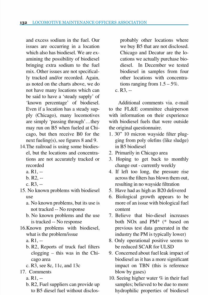
7/25/2019 Lmoa2013 Book Web Final
http://slidepdf.com/reader/full/lmoa2013-book-web-final 134/252
132 LOCOMOTIVE MAINTENANCE OFFICERS ASSOCIATION
and excess sodium in the fuel. Our
issues are occurring in a location
which also has biodiesel. We are ex-amining the possibility of biodiesel
bringing extra sodium to the fuel
mix. Other issues are not specical-
ly tracked and/or recorded. Again,
as noted on the charts above, we do
not have many locations which can
be said to have a ‘steady supply’ of
‘known percentage’ of biodiesel.Even if a location has a steady sup-
ply (Chicago), many locomotives
are simply ‘passing through’…they
may run on B5 when fueled at Chi-
cago, but then receive B0 for the
next fueling(s), see gures 8 and 9.
14.The railroad is using some biodies-
el, but the locations and concentra-tions are not accurately tracked or
recorded
a. R1, --
b. R2, --
c. R3, --
15. No known problems with biodiesel
use
a. No known problems, but its use is
not tracked -- No response
b. No known problems and the use
is tracked -- No response
16.Known problems with biodiesel,
what is the problem/issue
a. R1, --
b. R2, Reports of truck fuel lters
clogging – this was in the Chi-
cago area c. R3, see 8c, 11c, and 13c
17. Comments
a. R1, --
b. R2, Fuel suppliers can provide up
to B5 diesel fuel without disclos-
ing same. Therefore, there are
probably other locations where
we buy B5 that are not disclosed.
Chicago and Decatur are the lo-cations we actually purchase bio-
diesel. In December we tested
biodiesel in samples from four
other locations with concentra-
tions ranging from 1.5 – 5%.
c. R3, --
Additional comments via. e-mailto the FL&E committee chairperson
with information on their experience
with biodiesel fuels that were outside
the original questionnaire.
1. 30” 10 micron wayside lter plug-
ging from poly olens (like sludge)
in B5 biodiesel
2. Primarily in Chicago area3. Hoping to get back to monthly
change out - currently weekly
4. If left too long, the pressure rise
across the lters has blown them out,
resulting in no wayside ltration
5. Have had as high as B20 delivered
6. Biological growth appears to be
more of an issue with biological fuel
content
7. Believe that bio-diesel increases
both NOx and PM* (* based on
previous test data generated in the
industry the PM is typically lower)
8. Only operational positive seems to
be reduced SCAR for ULSD
9. Concerned about fuel leak impact of
biodiesel as it has a more signicantimpact on TBN (this is reference
blow by gases)
10. Seeing higher water % in their fuel
samples; believed to be due to more
hydrophilic properties of biodiesel
constituent

7/25/2019 Lmoa2013 Book Web Final
http://slidepdf.com/reader/full/lmoa2013-book-web-final 135/252
Industrial Specialty Chemicals Inc.
16888
S
Lathrop Avenue
Ha
rvey
IL
60462
708- 9-1313
IndustrialSpecialtyChemicals.com
Proud
Supplier
for
Your Tre.atment Needs
for
over 25
Ye ars
Waste Water Treabnent, Waste Oil Reduction Env
ir
onmental Solutions,
Lo... m
otive
Cool
ant and A n t i - F r ~ . . z e
C )ffosio
n
Inhibitors, Lo... m
otive
:md Car Cleaners
Hea>y :md
Light Duty General
Putpose Cleaners
Freight and Light Rail
America Canada Europe Asia Mexico India

7/25/2019 Lmoa2013 Book Web Final
http://slidepdf.com/reader/full/lmoa2013-book-web-final 136/252
134 LOCOMOTIVE MAINTENANCE OFFICERS ASSOCIATION
11. Asked the OEM’s about potential
problems with water in the fuel at
common rail fuel pressures of ~28kpsi that we will likely see in T4 en-
gines
12.Biodiesel will also eat some sealing
materials (concerns for both way-
side fueling systems and engines).
13.Investigation is ongoing, but chang-
ing to Viton ** seals is likely nec-
essary (** Viton, trade name fromDupont, a uoroelastomer)
14.One railroad have had some units in
IL run for 9 months on B20 (caveat
for extrapolation of results)
a. service was comparatively light
b. soy based
c. results may differ for different
feedstock d. at idle, the engine does not burn
all of the fuel
e. resulting in lube oil fuel dilution
DISCUSSION:
Currently there exists a perception
of increasing fuel problems, with the
belief by some that all the problems are
in part a result of the increasing use of
biodiesel blended fuels. Prior to mak-
ing such a blanket statement, the facts
need to be gathered, e.g., was the loca-
tion using biodiesel blends, the concen-
tration of the biodiesel blends, and was
the fuel tested to determine if it meets
specications, and the supplier infor-mation. Therefore, to elicit additional
information that would support or not
support if a given fuel issue was or was
not attributed to the use of biodiesel the
questionnaire/survey was distributed
to railroads. Once all the inputs were
received, the questionnaire answers
provided insight/information on: the
number of locations using biodiesel,diesel supply variations, biodiesel con-
centrations, variation in biodiesel con-
centrations, and existing fuel issues be-
lieved to be a result of using biodiesel
fuels. With this information one can
extrapolate a possible future use such
as increasing volume and/or increased
concentrations of biodiesel blendedfuels. Furthermore, with this infor-
mation, quality control programs such
as the one recommended in a LMOA
2008 paper on best practices7, could be
in place to address fuel related issues
and mitigate the impact.
There were reports of both wayside
and locomotive fuel system problemscorresponding with the introduction of
low concentrations of biodiesel blends,
starting in approximately 2007 to 2009,
into some of the railroads’ fuel supply.
The wayside problems reported were
fuel leaks in the fuel systems supply
pumps and control valves, to premature
plugging of wayside lters. On the lo-
comotives there were reports of short
lter life, to injector problems. How-
ever, before assigning fault to the use
of biodiesel blended fuels, the primary
cause must be determined. Not only
has there been an increase in the use of
biodiesel blends, but there was also a
shift from high sulfur diesel (HSD) to
ultra-low sulfur diesel (ULSD) alongwith variation in aromatic content. The
change from HSD to ULSD diesel fuel
supply was mandated by the EPA1.
With two major changes to the die-
sel fuel supply, the primary contribut-
ing factor should be determined before
7/25/2019 Lmoa2013 Book Web Final
http://slidepdf.com/reader/full/lmoa2013-book-web-final 137/252
FUEL, LUBRICANTS AND ENVIRONMENTAL 135
assumptions are made. The issue could
be the ULSD, biodiesel blends, or a re-
sult of reaction/interaction of the blend-ed fuels. Therefore, it is important to
know the primary contributing factor or
factors before corrective actions can be
appropriately applied.
It has been remarked by committee
members that some perceive diesel fuel
as a homogenous uid composed of
one compound. They are not. Distillatefuels (petroleum) are composed of hun-
dreds if not thousands of different mo-
lecular compounds. The same percep-
tion can be found for biodiesel, i.e., it is
comprised of one compound. They are
not. However, biodiesel fuels contain
relatively few different sulfur free fatty
acid methyl ester (FAME) hydrocarboncompounds compared to diesel fuels.
A LMOA 20052 paper on biodiesel fu-
els in railroad applications illustrated
the chemical structure of some of the
biodiesel compounds; whereas a 20076
LMOA paper on HSD and ULSD illus-
trated several of the diesel fuel chemi-
cal structures. The differences in the
structures of the two fuels were clearly
represented in those papers. Recogniz-
ing that there are unique chemical and
physical properties present that are dif-
ferent between diesel fuels (petroleum)
and biodiesel (FAME), those differ-
ences must be understood in terms of
operational and performance differ-
ences of both wayside systems and thelocomotive systems.
The blow-by gases from the fuels
with different concentrations of sulfur,
aromatics, and biodiesel will contain
different organic species than the previ-
ous used HSD fuels. This could require
railroads using infrared spectrometer
or other analytical instrumentation for
used oil analysis to account for the dif-ference in the fuel’s sulfur, aromatic,
and biodiesel content in their algo-
rithms, i.e., recalibration of some of the
analytical instruments used to evaluate
used oil. The increasing use of ULSD
has resulted in improvements to some
of the used oil parameters, e.g., base re-
tention and a reduction in oil’s sulfatedash by lowering the base number (BN)
down from 17 to 9. However, the in-
creasing use of biodiesel’s impact on
crankcase oil and locomotive systems
needs to be determined from long-term
eld studies
The shift from HSD high aromatic
diesel fuels to ULSD lower aromaticfuels with the corresponding use of low
concentrations of biodiesel fuels adds
complexity to the analytical evaluation
of fuel related problems.
Initial response from railroad 1
(R1) had not reported any problems in
their wayside fuel systems or locomo-
tives. However, it should be noted that
this railroad’s report of no problem was
from three of their fueling locations
where the purchased biodiesel blends
started the summer of 2012. It was also
noted the use of biodiesel blends were
suspended in the winter. After the initial
response this railroad increased the use
of biodiesel from three to seven loca-
tions. Of those seven locations three ofthe locations could not drain the water
from the tank bottoms. This resulted
in a major water and microorganism
contamination. On the other hand, rail-
roads 2, 3, and additional comments
from one of the Diesel Mechanical

7/25/2019 Lmoa2013 Book Web Final
http://slidepdf.com/reader/full/lmoa2013-book-web-final 138/252
136 LOCOMOTIVE MAINTENANCE OFFICERS ASSOCIATION
committee members reported issues at
locations being supplied B11 products,
and both R2 and R3 with some locomo-tives with less than B5.
R3 has shared information on in-
jector problems on a locomotive that
was in storage for three months. Prior
to storage the locomotive was burning
B20, see gures 8 and 9. This rail-
road’s laboratory also reported genset
locomotives running on approximately5% biodiesel have experienced numer-
ous failures of HPCR injectors due to
pilot valves becoming ‘stuck’ due to
carboxylate lm build-up. Additional
testing by R3 on fuel lter’s deposited
material found it was compromised of
compounds/chemicals that are com-
monly found in the makeup of bio-diesel blended fuels, i.e., analysis on
pasty residue deposited on fuel lters
revealed the deposits were mainly pal-
mitate (C16:0) and stearate (C18:0)
monoglycerides.
Examples of some of the difcul-
ties in identifying the actual source/lo-
cation of a fuel supply that is creating
a fuel related problem are as follows:
• B11 is being supplied into Chicago
area
o B11 is blended into the main stor-
age tanks to make something less
than B5.
o However, not all locomotives
passing though Chicago area are
topped up with fuel in Chicago.o The problem fuel is from another
terminal.
o If fueled in Chicago, the biodiesel
blend concentrations vary
o Problem fuel is often consumed
before fuel specimens are collect-
ed for analysis. • Must rely on analyzing the fuel
lters to determine contributing
factors
• The carboxyl salts (soaps) detected
on lters fouled/plugged can have
been created via different source
materials:
o Pipe line corrosion inhibitors (car-boxylic acids) reacting with an
alkali metal such as sodium or al-
kaline earth metal such as calcium
to form the carboxyl salt (soap)
o Biodiesel decomposition products
(organic acids) react with an alkali
metal such as sodium or alkaline
earth metal such as calcium toform the carboxyl salt (soap)
o With a quality analytical labora-
tory the difference between a
carboxyl salt formed from a cor-
rosion inhibitor and that formed
from a biodiesel compound can
sometimes be determined.
• Some fuel terminals are receiving
low concentrations (nil to B5) with-
out being reported to the railroad
The regional differences in the ba-
sic diesel fuels’ chemical and physical
properties and that of the biodiesel fu-
els should be evaluated for compatibil-
ity, solubility, miscibility, and fungibil-
ity before blending the two fuels. Thisevaluation could highlight or identify
potential problems so corrective action
can be applied before blending the fu-
els; thereby potentially avoiding some
fuel related problems, i.e., address the
problem in the infancy stage.

7/25/2019 Lmoa2013 Book Web Final
http://slidepdf.com/reader/full/lmoa2013-book-web-final 139/252
FUEL, LUBRICANTS AND ENVIRONMENTAL 137
Because of the variation in fuel
properties and measurements one can-
not rely completely on the laboratorytest results that affect performance.
“When using fuel oils, it is not wise to
put complete faith in all analyses, since
they sometimes appear satisfactory, but
actually are not. Two different oils can
have approximately the same analysis,
but will burn differently.”3 Additional
tests are often required to more com-pletely understand the interactions of the
fuels supplied and engine performance.
CONCLUSIONS:
The following points were extract-
ed from the fuel survey information
provided from the railroads.
• Biodiesel is used in the US and Canada• Biodiesel is not used at all fueling lo-
cations
• Biodiesel supply concentration var-
ies from nil to B20 at a given location
• Biodiesel concentration supply in
the storage tanks and locomotives
vary over time, i.e., not consistent
• Chicago region appears to be sup-
plied with a B11
• The B11 fuels are splashed blended
into the main fuel tanks at those lo-
cations
• Biodiesel is metered into main stor-
age on one railroad to make a B5
fuel
• Railroads are likely receiving some
diesel fuel pre-blended with bio-diesel at some terminals
• On occasion, blends greater than B5
make it into locomotives
• The trend is for an increasing use of
biodiesel, and possible higher concen-
tration blends, greater than 5 percent
• Railroads are testing some of the
fuel supply to determine if it is a
blended fuel• The recorded use of biodiesel fuel
at one major US railroad is increas-
ing each year from the late 2000s to
present
• Issues with B0 to B20 have been re-
ported, both in wayside systems and
on locomotives
• Issues locomotive testing with B20have been reported (railroad 2, 3,
and 4)
The current fuel supply varies not
only from railroad to railroad, but there
are variations of fuel supply at differ-
ent locations within a given railroad
system and at the same location. Thevariations observed include not only
biodiesel content but also other diesel
fuel properties, e.g., fuel sulfur, aro-
matic content, volumetric energy con-
tent, density, cetane, lubricity, and other
properties.6
RECOMMENDATION:
• Wayside fuel system suppliers eval-
uate all seals material and metal al-
loys use in pumps, valves, and hoses
for compatibility with biodiesel fu-
els.
• OEM locomotive suppliers evaluate
all seals material and metal alloys
use in pumps, valves, and hoses forcompatibility with biodiesel fuels
• Fuels are to be tested to determine
if they meet the specications, i.e.,
diesel, biodiesel, and blended fuels
at an acceptable frequency.
• Evaluation of the possible use of

7/25/2019 Lmoa2013 Book Web Final
http://slidepdf.com/reader/full/lmoa2013-book-web-final 140/252
138 LOCOMOTIVE MAINTENANCE OFFICERS ASSOCIATION
fuel additive packages to help solve
some of the fuel related problems
highlighted in this paper due to bio-diesel blends.
• Controlled biodiesel fuel eld tests,
as such as the one recommended in
a 2012 paper, LMOA FL&E: Loco-
motive Durability Test Protocol for
Alternate Fuels and Biodiesel5 be
conducted, and/or AAR’s 1983 fuel
elds test8
, for a completely evalu-ated long term durability, reliability,
and availability of not only the loco-
motives, but also the wayside fuel-
ing systems.
• If it is found the specications miss
important chemical or physical
properties or the limits need to be
adjusted, recommend to the ASTMimprovements to specications.
• When storing locomotives that
had been burning biodiesel fuels
it would be recommended that the
proper storage procedure be fol-
lowed as documented in the LMOA
2011 best practices paper10.
• Request that information be shared
from entities that have conducted
their own condential controlled
eld tests that followed the AAR’s
1983 eld test protocol8, the LMOA
2012 suggested eld test protocol5,
or other quality eld test protocols.
SUMMARY:Responses from the questionnaire
provided information on the current use
of biodiesel fuels, concentrations of the
supply, variation in consistency of sup-
ply, laboratory testing, examples of fuel
issue where biodiesel are used, and an
increasing trend in the use of biodiesel
blends.
In addition to locations where bio-diesel blends are a purchased commod-
ity, some of the railroads’ general fuel
supply does contain biodiesel blends
of varying concentrations. If the cur-
rent trend continues, there will be an
increased use of biodiesel blends, pos-
sibly at higher concentrations.
Analytical test evaluation ofplugged fuel lters, leaking wayside
fueling systems seals, and suck/dam-
aged locomotive fuel injectors have
implicated biodiesel fuel as one of the
contributing factors in the malfunc-
tions.
The current fuel composition and
future changes to railroad’s fuel sup-ply could require several adjustments
to the railroads’ fueling infrastructure,
locomotive maintenance, and locomo-
tive maintenance intervals.
Providing fuel products with con-
sistent high quality and properties are
paramount in overall railroads infra-
structure and locomotive performance.
The general consensus of the
LMOA FL&E committee, (and sup-
ported with yearly tracking) is that
there will be an increased use of bio-
diesel, possibly at higher concentration.
With the advent of greater use of
high pressure common rail fuel sys-
tems in new locomotives, fuel cleanli-
ness and water content in the fuel arewatch-points going forward. This may
be addressed in a future paper.

7/25/2019 Lmoa2013 Book Web Final
http://slidepdf.com/reader/full/lmoa2013-book-web-final 141/252
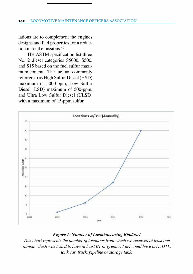
7/25/2019 Lmoa2013 Book Web Final
http://slidepdf.com/reader/full/lmoa2013-book-web-final 142/252
140 LOCOMOTIVE MAINTENANCE OFFICERS ASSOCIATION
lations are to complement the engines
designs and fuel properties for a reduc-
tion in total emissions.”2 The ASTM specication list three
No. 2 diesel categories S5000, S500,
and S15 based on the fuel sulfur maxi-
mum content. The fuel are commonly
referred to as High Sulfur Diesel (HSD)
maximum of 5000-ppm, Low Sulfur
Diesel (LSD) maximum of 500-ppm,
and Ultra Low Sulfur Diesel (ULSD)with a maximum of 15-ppm sulfur.
Figure 1: Number of Locations using Biodiesel
This chart represents the number of locations from which we received at least onesample which was tested to have at least B1 or greater. Fuel could have been DTL,
tank car, truck, pipeline or storage tank.

7/25/2019 Lmoa2013 Book Web Final
http://slidepdf.com/reader/full/lmoa2013-book-web-final 143/252
FUEL, LUBRICANTS AND ENVIRONMENTAL 141
Figure 2: Number of Locations using Biodiesel by Quarter
Same info as gure, 1 but broken down by quarter. The rate is clearly variable
Figure 3: Concentration of biodiesel, B0 to B5 at those locations
This chart displays the concentration of biodiesel received over time at 13 locations
across the system. The biodiesel level is clearly not consistent over time. Also note, the
data points are connected for clarity – this does not indicate the BXX percent followed
the line specically, especially if a long time interval is involved

7/25/2019 Lmoa2013 Book Web Final
http://slidepdf.com/reader/full/lmoa2013-book-web-final 144/252
142 LOCOMOTIVE MAINTENANCE OFFICERS ASSOCIATION
Figure 4: Additional images – Filter Plugging 2011-2012:
Monoglyceride crystals beginning to form in B100 biodiesel after being held
at 40F for 3 days
Figure 5: – end result, B100 held at 40F for 3 weeks. 40F was far above the classic
‘cloud point’ of the fuel

7/25/2019 Lmoa2013 Book Web Final
http://slidepdf.com/reader/full/lmoa2013-book-web-final 145/252
FUEL, LUBRICANTS AND ENVIRONMENTAL 143
Figure 6: Pasty residue recovered from plugged lters. Analysis revealed mainly
palmitate (C16:0) and stearate (C18:0) monoglycerides.
Figure 7: Early Detection – Filter Plugging 2013
A ‘brown cloud’ of material was found to form during an in-house cold soak lter
plugging test of mixed B5 fuel at approximately 40ºF. Detection of this helped avert
a major lter plugging incident. The fuel was found to fully meet all other applicable
specications for quality. ASTM D2500 cloud point was approximately 0ºF.
Second ‘brown cloud’ issue noted in April 2013. Same fuel test parameters listed
above. Fuel is approximately B5 concentration with 0.004% water by Carl Fischer
water titration. ASTM D2500 cloud point was approximately 0ºF.

7/25/2019 Lmoa2013 Book Web Final
http://slidepdf.com/reader/full/lmoa2013-book-web-final 146/252
144 LOCOMOTIVE MAINTENANCE OFFICERS ASSOCIATION
Figure 8: HPCR Injector with sticking pilot valve
Figure 9: HPCR Injector with sticking pilot valve

7/25/2019 Lmoa2013 Book Web Final
http://slidepdf.com/reader/full/lmoa2013-book-web-final 147/252
Total ailroad iltration
Customers are always 1 at Clark Filter.
We are driven to provide fair prices con
sistent quality and the fastest delivery
in the industry.
Call us toll free
at
1-800-55-CLARK
r
visit our web site:
IS09001
Registered
www.clarkfilter.com
CL RKFILTER
Ct AACOit ~
he
premier prochK:er or locom otive
ftlters worldwide

7/25/2019 Lmoa2013 Book Web Final
http://slidepdf.com/reader/full/lmoa2013-book-web-final 148/252
146 LOCOMOTIVE MAINTENANCE OFFICERS ASSOCIATION
Introduction
The role of lubricating and fuel oil
lters on diesel locomotives has beenand will continue to be critical in the
operation and maintenance of these
costly and increasingly sophisticated
machines. The applications and tech-
nology of locomotive ltration have
changed signicantly since the early
days of dieselization as reected in the
continual evolution of element ltra-tion media, element conguration and
lter maintenance intervals over the
past half-century.
The purpose of this paper is to
provide a general overview of diesel
locomotive lube and fuel ltration
while focusing attention on the fol-
lowing topics:A) Principles & Functions of Filtration
B) Principles of Filter Testing
C) Evaluation of Filter Performance
D) Locomotive Filter Applications
E) Future Trends & Challenges
Preface Statement
While it is not the purpose of this
paper to prove through research or em-
pirical data the correlation between l-
tration and locomotive reliability, it is
generally accepted that proper ltration
can and will reduce engine wear, en-
gine failures and reduce unit exchange
scrap rates.
A. Principles & Functions of
Filtration
1. Filtration: The process of collect-ing solid particles from a contaminated
uid by passage of that uid through a
permeable medium where the particles
are retained.
2. Function of Filtration: Remove par-
ticulate (insoluble contaminant) thatcontributes to the wear or deterioration
of critical engine components.
3. Insoluble Contaminants
a) Built-In: Residual from the
fabrication process
• Casting sand
• Metal working chips
• Weld slag
b) Ingressed: Enter engine from
external environment
• Airborne dust & dirt
• During routine maintenance
activities
Locomotive Fuel & Lubricant Oil Filters 101
Prepared by:
Peter Whallon, Clark Filter
&
Jonathan George, Ph.D., Parker Filtration Canada

7/25/2019 Lmoa2013 Book Web Final
http://slidepdf.com/reader/full/lmoa2013-book-web-final 149/252
FUEL, LUBRICANTS AND ENVIRONMENTAL 147
c) Generated: Products of normal
engine operation
• Combustion soot• Wear metal particulate
• Lube oil oxidation by-products
• Lube oil acid neutralization
by-products
• NOTE: do not miss required
oil change outs!
B. Principles of Filter Testing1. What is a “Micron”?
a) Measure of length (µm or µ)
b) Common terminology
• “micron”
• “micrometer”
c) Conversion factors
• 1 micron = 1/1,000,000 meter
= 1/25,400 inchd) Relative sizes
• 40µ = smallest visible with
naked eye
• 75µ= diameter of average hu-
man hair
2. Filter Ratings
a) Are Not:
• Universally dened
• Consistently applied by lter
manufacturers
• Well-served by terminol-
ogy as “nominal”, “absolute”,
“average”
• Determined by media pore size
b) Are:
• Needed for commonalitywithin an industry
• Applicable only to a particu-
lar test procedure (measure of
test results)
• Best expressed in terms of “Fil-
tration Ratio” (multi-pass test)
3. Multi-Pass Filter Test
a) Developed in 1978 at Okla-
homa State Universityb) Measures separation efcien-
cy at selected particle sizes
c) Measures dust-holding capac-
ity at specied terminal pres-
sure
d) Most accurate & objective
method for comparing lter
performanceNOTE:
• laboratory test results do not
necessarily relate directly to
eld performance
• test results best for purposes
of lter comparison & prod-
uct development
4. Filtration Ratio (“F.R.”)
a) Determined by multi-pass test
b) Best measure of a lter’s abil-
ity to remove particulate con-
tamination
c) Derived from the ratio of up-
stream to downstream par-
ticles
NOTE: Filtration Ratio is a se-
verely non-linear function of
efciency

7/25/2019 Lmoa2013 Book Web Final
http://slidepdf.com/reader/full/lmoa2013-book-web-final 150/252
148 LOCOMOTIVE MAINTENANCE OFFICERS ASSOCIATION
5. Filter Efciency
6. Filter Capacity
a) Measure of a lter’s ability to
maintain permeability during
the ltration process
b) Determined by pressure drop
resulting from increased con-
taminant loadingc) Amount of contaminant re-
tained by lter at specied
terminal pressure

7/25/2019 Lmoa2013 Book Web Final
http://slidepdf.com/reader/full/lmoa2013-book-web-final 151/252
FUEL, LUBRICANTS AND ENVIRONMENTAL 149
C. Evaluation of Filter Performance
1. Filter Capacity vs. Efciency
a) Inverse relationship betweencapacity and efciency
2. System Flow Rate vs. Filter Perfor-mance
a) Capacity and efciency vary
inversely with ow rate
• As ow rate increases, lter
capacity decreases
• As ow rate increases, lter
efciency decreases
b) Filter System By-Pass Leak-
age

7/25/2019 Lmoa2013 Book Web Final
http://slidepdf.com/reader/full/lmoa2013-book-web-final 152/252
150 LOCOMOTIVE MAINTENANCE OFFICERS ASSOCIATION
3. Common Causes
• Filter media by-pass due to
handling damage• Defective element-to-housing
interface seal
• Malfunctioning by-pass or
relief valve
• Element by-pass due to con-
struction defect
NOTE: Prevention of by-pass
far more critical than achiev-ing high ltration ratios
D. Locomotive Filter Applications
1. Lube Oil Strainers
a) Primary Function
• Protection for lube oil pumps
b) Geometries
• Cartridge
• All-metal construction
c) Filter Media
• Wire mesh (ne or coarse)d) Service Interval
• Cleanable

7/25/2019 Lmoa2013 Book Web Final
http://slidepdf.com/reader/full/lmoa2013-book-web-final 153/252
FUEL, LUBRICANTS AND ENVIRONMENTAL 151
2. Turbo & Soak Back Filters
a) Primary Function
• Protection of EMD turbo-charger bearings
b) Geometries
• Spin-on
• Cartridge
c) Filter Media
• Pleated paper
• Typical micron size: 20µ
d) Service Interval• 92-184 days
3. Main Lube Oil Filters
a) Primary Function
• Protect against engine and
bearing wear
b) Geometries
• Cartridge (6”x30”)c) Filter Media
• Pleated paper
• Typical micron size:
12µ, 20µ, 30µ
d) Service Interval
• 92-184 days
4. Fuel Strainers
a) Primary Function
• Protection of fuel transfer
pump
b Geometries
• Cartridge
• Spin-on
c) Filter Media
• Pleated wire mesh
• Typically 30-mesh (~600µ)d) Service Interval
• 92-184 days

7/25/2019 Lmoa2013 Book Web Final
http://slidepdf.com/reader/full/lmoa2013-book-web-final 154/252
152 LOCOMOTIVE MAINTENANCE OFFICERS ASSOCIATION
5. Primary Fuel Filters
a) Primary Function
• Protection of injector pumps &nozzles
b) Geometries
• Cartridge (10” O.D.)
• Length: 30” or 45”
• Cartridge segments: 1, 2 or 3
• Filtration-type: single or double-pass
c) Filter Media
• Pleated paper• Typical micron size: 5µ, 12µ
d) Service Interval
• 92-184 days
6. Secondary Fuel Filters
a) Primary Function
• Protection of injector pumps &
nozzlesb) Geometries
• Spin-on
• Cartridge
c) Filter Media
• Pleated paper
• Typical micron size: 5µ, 12µ
d) Service Interval
• 92-184 days
7. Wayside Fuel Filters
a) Fuel Pumping Stations
• Protection of locomotive injector
pumps & nozzles
b) Geometries
• Cartridge (6”, 10” O.D.)
• Length: 30”
• Cartridge segments: 1 or 2• Filtration-type: single or double-pass
c) Filter Media
• Pleated paper
• Typical micron size: 10µ
d) Service Interval
• Determined by pressure drop and/or
time interval

7/25/2019 Lmoa2013 Book Web Final
http://slidepdf.com/reader/full/lmoa2013-book-web-final 155/252
FUEL, LUBRICANTS AND ENVIRONMENTAL 153
E. Future Trends & Challenges
1. Advanced fuel system technology
will drive need for improved ltrationa) Common rail fuel injection
systems require fuel with very
low water content and will
need to incorporate on-board
water/fuel separators.
b) Common rail fuel systems
will require fuel with high de-
gree of particulate cleanlinessvia on-board lters with in-
creased efciency as much as
ve times greater than Tier 2.
2. Language of fuel ltration evolv-
ing from “Filtration Ratio” to “ISO
Code”
3. ISO Code
a) Measure of lter performance
testing per SAE J1985b) Results reported in “particles
per milliliter” at specic mi-
cron-sizes
c) Utilizes 3-number system to
classify uid cleanliness at
4µ, 6µ, 14µ
d) Example: ISO Code =
“12/9/7”• “12” designates level of uid
cleanliness at particle size 4µ
and larger
• “9” designates level of uid
cleanliness at particle size 6µ
and larger
• 7” designates level of uid
cleanliness at particle size14µ and larger

7/25/2019 Lmoa2013 Book Web Final
http://slidepdf.com/reader/full/lmoa2013-book-web-final 156/252
154 LOCOMOTIVE MAINTENANCE OFFICERS ASSOCIATION
4. Challenges Ahead
a) Will locomotive ltration
needs change in the fu-ture?........YES!
b) Major factors affecting ltra-
tion system performance
• Fuel types (i.e. ULSD, bio-
diesel, natural gas)
• Cold weather issues
• Water issues (greater ten-
dency to attract & retainmoisture)
• Solvency issues (fuel sys-
tem deposits, component
compatibility)
• Carboxylate soap deposits
• Fuel injection technology
requirements (high pressure
common rail)c) New on-board and wayside
ltration technologies
• High-efciency particulate
removal
• Water separation & removal
Summary
Quality lubricating and fuel oils,
commonly considered the “lifeblood”
of a diesel locomotive engine, are es-
sential to achieving long and reliable
performance from these high-output
machines from which so much is de-
manded over the typical 20+ year life
cycle. At the same time, the impor-
tance of good ltration of these critical
engine uids cannot be overstated rel-ative to the needs of today’s railroads
for long-term, dependable locomotive
service.
Locomotive ltration technology
has continued to evolve in accordance
with changes and improvements in
diesel engine design. Those changes
require improved quality of ltration to
better protect the components and sys-tems delivering ever-increasing levels
of engine performance. New fuel for-
mulations and advances in locomotive
technology borne from low-emissions
requirements have resulted in signi-
cant challenges for locomotive ltra-
tion. However, as the railroad lter
supply community has proven capablein the past of meeting emerging indus-
try and technology needs, it again wel-
comes the challenges that lie ahead.
Acknowledgements
The authors would like to thank
all members of the Fuels, Lube & En-
vironmental committee for their assis-tance and counsel in the preparation of
this paper.

7/25/2019 Lmoa2013 Book Web Final
http://slidepdf.com/reader/full/lmoa2013-book-web-final 157/252
FUEL, LUBRICANTS AND ENVIRONMENTAL 155
LMOA Generation 5 locomotive
medium speed diesel engine oil per-
formance standard was successfullydened in 1989 to effectively address
changes in locomotive engine design,
utilization and maintenance that had
signicantly changed from the intro-
duction of the previous generation oil
in 1976. Due to Environmental Protec-
tion Agency (EPA) fuel and emission
regulations, locomotive engine design,utilization and maintenance have been
signicantly impacted. Chemical and
physical performance attributes of lo-
comotive engine oils were researched,
developed and eld tested to meet these
compounding factors.
The 2009 paper presented by the
Fuels, Lubricants and Environmental(FL&E) Committee of the Locomo-
tive Maintenance Ofcer’s Associa-
tion (LMOA), titled “New Generation
Oil Additive Technology for Locomo-
tive Engines Operating on Low and
Ultra-Low Sulfur Diesel Fuel” details
a multi-year effort to identify and suc-
cessfully eld test a new low ash loco-
motive engine oil additive technology.
The table below is taken from the ref-
erenced paper and has been updated
to include the addition of two (2) new
generations in the classication system.
LMOA Generation 6 locomotive
engine oils are formulated to address
the consumption of low (≤500 ppm)
and ultra-low (≤15 ppm) sulfur diesel
via an optimized lubricant additivepackage with consideration for envi-
ronmental emission concerns.
The FL&E committee denes
Generation 6 diesel locomotive engine
oil performance attributes and qualities
per the following:
• The nished oil formulations must
demonstrate good deposit and wear
control, alkalinity retention, viscos-
ity control, thermal & oxidative sta-
bility, engine cleanliness & sludge
control in locomotives that have
lower oil consumption resulting in
longer residence time of the oil inthe engine’s sump
• The new nished oil formulation
must be suitable for use in locomo-
tive eets with Tier 3 and earlier lo-
comotive engine models
• The new locomotive engine oil ad-
ditive technology must be tested to
demonstrate acceptable compat-
ibility with existing original engine
manufacturers (OEMs) approved oil
formulations
Generation 6 Locomotive Engine Oil
PropertiesPrepared by:
Thomas E. Gallagher, Chevron Oronite Company LLC

7/25/2019 Lmoa2013 Book Web Final
http://slidepdf.com/reader/full/lmoa2013-book-web-final 158/252
156 LOCOMOTIVE MAINTENANCE OFFICERS ASSOCIATION
LMOAGenera-
tion
EffectiveYear
TypicalBN
PerformanceMilestones ofLocomotive Engine Oil
Advancements
Formulation Issues
1 1940 <7 Straight mineral oils Lost alkalinity, lead corro-
sion, bearing failures
2 1964 7 Ashless dispersants,
improved alkalinity withcalcium detergents
Reduced sludge & better oil
ltration
3 1968 10 Improved alkalinity
retention, higher dis-persant levels, calcium
detergents
Reduced piston ring wear,
reduced corrosion
4 1976 13 Improved alkalinity
retention withimproved detergents &dispersants
Increased protection for
adverse engine operatingconditions
5 / 4LL 1989 13 / 17 / 18
Improved drain intervalsin low oil consumption
engines
Longer life oils that meet
LMOA denitions &requirements
6 2009 9 / 10 Optimized dispersant& detergent system for
low sulfur diesel (≤500ppm) & ultra low sulfurdiesel fuel (≤15 ppm)for low oil consumption
engines
Proper balance of lube oilalkalinity in considerationof fuel sulfur levels while
maintaining established oildrain intervals; concurrentwith reduction in sulfated
ash in the oil
7 TBD ? TBD – based on Tier 4
requirements
TBD – based on EPA Tier
4 requirements effectiveJanuary 1, 2015
Table 1. LMOA Locomotive Engine Oil Generations: New GEN 6 & 7
• Used oil analysis trending of the
nished oil formulation must dem-
onstrate the ability to maintain es-
tablished locomotive maintenance
intervals without breaching OEMs
used oil condemning limits
• The nished oil formulations must
pass all required tests by OEMs(e.g. oxidation, corrosion and fric-
tion tests)
• The nished oil formulation must
also be eld tested in accordance
with the following:
o Field testing must be conducted in
accordance with the procedures
prescribed in the LMOA FL&E
paper titled “Engine Lubricating
Oil Evaluation Field Test Proce-
dure” given in the year 2000o The eld test protocol must be
reviewed and approved by the
OEMs, host railroad and the ad-
ditive company

7/25/2019 Lmoa2013 Book Web Final
http://slidepdf.com/reader/full/lmoa2013-book-web-final 159/252
FUEL, LUBRICANTS AND ENVIRONMENTAL 157
o The select locomotive engines
must be operated in a service hav-
ing a severity level acceptable tothe OEMs
o Resultant eld test data must be
reviewed by the OEMs for issu-
ance of approval and recognition
letters
• The use of a LMOA Generation 6
oil is not recommended for use inlocomotives consuming diesel fu-
els with a sulfur content exceeding
500 ppm
LMOA Generation 7 locomotive
engine oils will be required to address
engine modications necessary to meet
2015 EPA Tier 4 Emission Standardsfor locomotives. Reference Table 1.
Engine design, metallurgy, and use of
emission reduction technologies, (e.g.
diesel oxidation catalysts, diesel partic-
ulate lters, exhaust gas recirculation,
selective catalytic reduction, etc…)
will signicantly inuence engine oil
properties and performance attributes.
The FL&E committee will con-
tinue its efforts to ensure that the lu-
brication needs of modern locomo-
tives are met.
7/25/2019 Lmoa2013 Book Web Final
http://slidepdf.com/reader/full/lmoa2013-book-web-final 160/252
158 LOCOMOTIVE MAINTENANCE OFFICERS ASSOCIATION
Report on the Committee
on New Technologies
Tuesday, October 1, 2013 at 8:45 A .M.
Chairman
Tom Mack Chairman of the LMOA New Technologies Committee
Cincinnati, OH
Vice ChairmanJeff ClapperSupt-Motive Power
Wheeling & Lake Erie Rwy
Commitee MembersS. Bendriss Electrical Engineer-Propulsion Amtrak Wilmington, DE
A. Bennett Gen. Mgr of Engineering R.J. Corman Railpower Locos Erie, PA
D. Brabb AVP-R&D Sharma & Associates Countryside, IL
D. Brooks Product Development Mgr ZTR Control Systems London, OntarioT. Elkhatib Mgr-Mechanical Engineering Union Pacic RR Omaha, NE
K. Gilbert Vice President-Sales Miller Ingenuity Corp Candiac, Quebec
P. Hess Mech Engineer-Locomotive Design Norfolk Southern Corp Atlanta, GA
B. Kehe Chief Mech Ofcer Chgo, South Shore Michigan City, IN
(Past President) & So Bend RR
R. Nelson Marketing Director Cummins, Inc Columbus, OH
C. Nordhues Sales Account Executive Nomad Digital Solutions Omaha, NE
T. Shah Product Mgr-Global Eng Platforms GE Transportation Erie, PA
D. Sweatt Telecommunications Project Mgr CSX Transportation Jacksonville, FL
K. Ulbick Sales Manager Peaker Services, Inc Brighton, MIJ. Whitmer Field Services Manager Motive Power Boise, ID
B. Wolff Sales Engineer-Rail MTU Detroit, MI
C. Wyka Senior Reliability Specialist CN RR Edmonton, Alberta
Note: Jason Smith will be replacing Tarek Elkhatib as UP replacement on this committee

7/25/2019 Lmoa2013 Book Web Final
http://slidepdf.com/reader/full/lmoa2013-book-web-final 161/252
NEW TECHNOLOGIES 159
P E R S O N A L H I S T O R Y
Tom Mack
Tom Mack has worked as Vice
President of Sales and Business
Development for Motive Power &
Equipment Solutions, Inc. since 2011.
Prior to joining MP&ES, Tom
Mack founded Alternative Hybrid
Locomotive Technologies (AHL-
TECH) in November 2005. Tomassembled a team of innovators from
the locomotive, biofuels, software,
and energy storage industries to
design the world’s rst ethanol
hybrid locomotive. While the AHL-
TECH hybrid never became reality,
the designs incorporated into the
locomotive and the computer models
developed, along with the experience
gathered from the project, have given
Tom a unique insight into locomotive
new technologies and the locomotive
market.
In addition to LMOA, Tom serves
on the Mechanical Committee for the
American Short Line and Regional
Railroad Association (ASLRRA), isa member of the FRA’s Natural Gas
Locomotive Research Task Force, and
works with the AAR Natural Gas Fuel
Tender Technical Advisory Group
(AAR NGFT TAG). He also served on
the SAE TC-7 Biodiesel in Rail com-
mittee.
Tom currently resides in Cincin-
nati, Ohio with his wife, Mary.

7/25/2019 Lmoa2013 Book Web Final
http://slidepdf.com/reader/full/lmoa2013-book-web-final 162/252
160 LOCOMOTIVE MAINTENANCE OFFICERS ASSOCIATION
The New Technologies Committee would like to
express their sincere appreciation to MTU and Bruce
Wolff for hosting our Winter meeting at the engine
plant in Aiken, South Carolina.
We would also like to thank Motive Power &
Equipment Solutions for hosting our Spring meeting
in Cincinnati, Ohio and the Cincinnati Railroad Club
for allowing us to meet in their facility in “Tower A”
at the Cincinnati Union Terminal.

7/25/2019 Lmoa2013 Book Web Final
http://slidepdf.com/reader/full/lmoa2013-book-web-final 163/252

7/25/2019 Lmoa2013 Book Web Final
http://slidepdf.com/reader/full/lmoa2013-book-web-final 164/252
162 LOCOMOTIVE MAINTENANCE OFFICERS ASSOCIATION
Since 1993 locomotive event re-corders have been required for heavy
and light-rail transportation systems.
These event recorders have been an
important tool in evaluating every-
thing from locomotive performance to
crew performance and are invaluable
in crash investigation and recreation.
In the 20 years since event recorders
became mandatory locomotives have
gone through major changes, especial-
ly in regard to the electronic systems
carried on-board. Each discrete elec-
tronic device seems to have its own set
of data that is collected. Even engines,
high voltage inverters, and some elec-
trical rotating equipment now provide
a wealth of data, from temperature, topower outputs, that can be tracked. All
of this information can have practical
application if collected and reviewed.
While much of this data is avail-
able, not all of it is actually collected.
What is collected may be transmitted
via remote monitoring systems to a
central site, but there are always in-tervals of time when data is not trans-
mitted but still available and collected
by onboard data acquisition systems.
Where do we store all this data on
the locomotive? Does it make sense
to store data in multiple systems on
the locomotive and have to retrieve itfrom multiple locations? What about
the new systems that record video or
audio? These systems require huge
amounts of data storage space. Most
importantly, what if our locomotive
is involved in an accident? Is the data
collected by all these systems safe?
Because of the growth of elec-
tronic systems on locomotives, the
AAR developed a new standard prac-
tice, Standard S-9101B adopted in
2011, to address Locomotive Data
Acquisition and Recording System
(LDARS) Architecture. This standard
applies to new locomotives ordered
after January 1, 2012, and states:
“The intent of this architecturestandard is to provide requirements
for the Locomotive Data Acquisition
and Recording System (LDARS) to
include the Event Data Acquisition
Processor (EDAP) and Crashwor-
thy Memory Module (CMM) storage
functions and a standardized interface
for retrieval of stored data. The EDAPand CMM requirements can be physi-
cal, logical, or electrical. The EDAP
will be expressed as either a process or
processor(s). A process is a functional
and a processor is a physical (device
or component) representation.”
LDARS and CMM
Prepared by:
Connie Nordhues
Nomad Digital Solutions
and
Tom Mack
Chairman of the LMOA New Technologies Committee

7/25/2019 Lmoa2013 Book Web Final
http://slidepdf.com/reader/full/lmoa2013-book-web-final 165/252
NEW TECHNOLOGIES 163
In addition to the AAR S-9101
standard, the following also come into
play:• CFR Title 49 Part 229.135 – Event
Recorders
• IEEE STD 1482.1-1999, IEEE
Standard for Rail Transit Vehicle
Event Recorders, 26 June 1999
• AAR Standard S-5702, “Railroad
Electronics Environmental Re-
quirements”
This paper is not designed to
provide all the information contained
in S-9101B, but it will acquaint the
reader with some of the highlights and
illustrate how this standard can be in-
corporated into a CMM device.
LDARS Overview
A Locomotive Data Acquisition
and Recording System (LDARS) isactually based on two distinct func-
tions that may or may not be com-
bined. The rst is the Event Data
Acquisition Process (EDAP) which
provides an interface to different
systems onboard the locomotive and
writes the data to the Crashworthy
Memory Module (CMM). The CMM,or CHMM (Crash Hardened Memory
Module) as it is sometimes called, is a
protected storage device similar to the
“Black Box” on an airplane that pro-
vides a high-survivability, protected
storage repository for all the accumu-
lated locomotive data.
The CMM must be able tosurvive extreme conditions. S-9109,
Table 2.1 requires the following envi-
ronmental conditions be able to be met
by the CMM:
Condition Requirement
Fire, high temperature 750 °C (1400 °F) for 60 minutesFire, low temperature 260 °C (500 °F) for 10 hours
Impact shock 55 g peak, 100 ms duration, 1/2 sine crash pulse, no less than28 m/s velocity area under curve, separately in the direction of
each of the three principal axes
Static crush 110 kN (25 000 lbf) for 5 minutes
Fluid immersion Immersion in any of the following individually for 48 hours: •grade 1 and 2 diesel fuel •salt water • lubricating oil Followed
by immersion in re-extinguishing uids for 10 minutes. Fol-lowed by 48 hours in a dry location without being otherwise
disturbed.
Hydrostatic pressure Immersion in salt water at a depth of 15 m (50 ft) for 48 hoursat a nominal temperature of 25 °C (77 °F)
Figure 1: S-9109 Table 2.1

7/25/2019 Lmoa2013 Book Web Final
http://slidepdf.com/reader/full/lmoa2013-book-web-final 166/252

7/25/2019 Lmoa2013 Book Web Final
http://slidepdf.com/reader/full/lmoa2013-book-web-final 167/252
NEW TECHNOLOGIES 165
Data Acquisition and Writing To /
Reading From the CMM
There is no specic data acqui-sition (sample rate) required for an
EDAP system. This is because differ-
ent events have different timing. For
example, some events may only need
to be monitored once per second, or
even less. This might include engine
temperatures, ambient temperatures,
etc. Other data may be monitored ev-ery few milliseconds. Still other data
may be event driven.
Once this data is acquired by a
locomotive system (e.g. an engine
monitoring/control system), it is up
to that discrete system to deliver the
information to the EDAP. The time be-
tween the discrete locomotive systemobtaining a piece of data and that data
being sent to the EDAP processor is
known as Data Sample Latency. There
is now specic standard for the maxi-
mum length of data latency before it
is passed to the EDAP and CMM sys-
tems. There is thus always the chance
some of this data could be lost in the
event of a catastrophic event. In real-
ity, this data loss should be minimal,
as long as discrete locomotive sys-
tems do not hold or “cache” the data
for excessive periods of time before
passing it on to the EDAP. Manufac-
turers of locomotive electronic system
should keep in mind, however, that
their data needs to be regularly sent tothe EDAP/CMM system and should
not be retained just within their own
system.
Data sent to the EDAP can be in
different formats, but the main func-
tion of the EDAP is to “normalize” or
convert the data into a common for-
mat if possible. This common format
is known as an EMP Class D messageformat. In this way the data sent to the
CMM is for the most part in a stan-
dardized form which requires minimal
processing by the CMM. This ensures
that any data sent to the CMM can be
as quickly as possible transferred to
the “safe” section of the CMM, the
crashworthy memory itself. Whilenewer electronic systems can take into
account an LDARS system, many old-
er systems may not, or a system may
be required to use an existing propri-
etary data format. EDAP allows for
this variation of data.
All data fed to the LDARS should
be time stamped from the originatingsystem. What though if data coming
from different sources has different
times on it, due to slight variances in
each systems internal clock setting?
Every data item stored in the CMM
is time-stamped. This time-stamp cre-
ated by the LDARS system is based
on a single, standard clock. In addi-
tion to this “standard” time stamp, the
LDARS system is mandated to main-
tain the “relative time” of the source
data, along with the “referenced” time
of the LDARS. In this way raw data
from the source system can be cross-
referenced with data in the LDARS.
When data is written to the
CMM, it is important that it is writ-ten in the right way. The CMM vendor
is required to use a “data overwrite”
scheme, not an “erase then add”
scheme, where the oldest data is over-
written rst. Since there are multiple
data feeds to the CMM, the memory

7/25/2019 Lmoa2013 Book Web Final
http://slidepdf.com/reader/full/lmoa2013-book-web-final 168/252
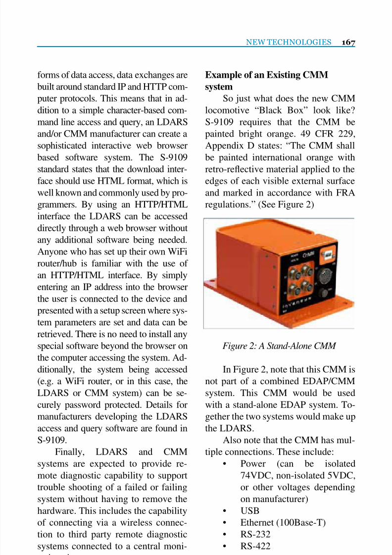
7/25/2019 Lmoa2013 Book Web Final
http://slidepdf.com/reader/full/lmoa2013-book-web-final 169/252
NEW TECHNOLOGIES 167
forms of data access, data exchanges are
built around standard IP and HTTP com-
puter protocols. This means that in ad-dition to a simple character-based com-
mand line access and query, an LDARS
and/or CMM manufacturer can create a
sophisticated interactive web browser
based software system. The S-9109
standard states that the download inter-
face should use HTML format, which is
well known and commonly used by pro-grammers. By using an HTTP/HTML
interface the LDARS can be accessed
directly through a web browser without
any additional software being needed.
Anyone who has set up their own WiFi
router/hub is familiar with the use of
an HTTP/HTML interface. By simply
entering an IP address into the browserthe user is connected to the device and
presented with a setup screen where sys-
tem parameters are set and data can be
retrieved. There is no need to install any
special software beyond the browser on
the computer accessing the system. Ad-
ditionally, the system being accessed
(e.g. a WiFi router, or in this case, the
LDARS or CMM system) can be se-
curely password protected. Details for
manufacturers developing the LDARS
access and query software are found in
S-9109.
Finally, LDARS and CMM
systems are expected to provide re-
mote diagnostic capability to support
trouble shooting of a failed or failingsystem without having to remove the
hardware. This includes the capability
of connecting via a wireless connec-
tion to third party remote diagnostic
systems connected to a central moni-
toring site.
Example of an Existing CMM
system
So just what does the new CMMlocomotive “Black Box” look like?
S-9109 requires that the CMM be
painted bright orange. 49 CFR 229,
Appendix D states: “The CMM shall
be painted international orange with
retro-reective material applied to the
edges of each visible external surface
and marked in accordance with FRAregulations.” (See Figure 2)
In Figure 2, note that this CMM is
not part of a combined EDAP/CMM
system. This CMM would be used
with a stand-alone EDAP system. To-
gether the two systems would make up
the LDARS.
Also note that the CMM has mul-
tiple connections. These include:
• Power (can be isolated
74VDC, non-isolated 5VDC,
or other voltages dependingon manufacturer)
• USB
• Ethernet (100Base-T)
• RS-232
• RS-422
Figure 2: A Stand-Alone CMM

7/25/2019 Lmoa2013 Book Web Final
http://slidepdf.com/reader/full/lmoa2013-book-web-final 170/252
168 LOCOMOTIVE MAINTENANCE OFFICERS ASSOCIATION
Any external connections, such as
power connectors, Ethernet, or serial
interfaces should use a robust MIL-spec connector. When discussing the
download interface, S-9109 speci-
cally mentions the use of an Ethernet
M12 connection. The M12 connection
is different from the RJ45 connec-
tion commonly used in the Ethernet
networks found in a home or ofce.
While both are adequately designedto maintain high data throughput and
reliability, the RJ45 connections com-
monly found in stationary networks
are not designed for the harsh mobile
environment on a locomotive. Hence
an M12 industrial Ethernet connection
is preferred. The same goes for other
connections on the CMM.In addition to the connections
shown above, the unit may also have:
• Ethernet (10Base-T – slower than
100Base-T)
• Wireless
In the unit shown in Figure 2, the
communications/CPU portion of the
CMM is contained in the smaller sec-
tion at the front of the unit (the FEM
or Front End Module), while the mem-
ory itself is in the larger section to the
rear of the unit (the PMM or Protected
Memory Module). Note that the larger
section in the rear is made of a much
thicker metal than the front section.
And if you think about the size of evena high capacity, multi-gigabyte USB
memory stick, it is clear that much of
the space for the actual memory por-
tion of the unit is simply steel and
insulation. It is not necessary for the
processor portion or connectors at the
front of the unit support a crash. As the
architecture block diagram in Figure 3
shows, what is critical to survive thecrash is the actual memory and front
end processor for the memory itself
which is housed in the PMM. This
ensures that the data can be accessed
and downloaded by the manufacturer
or accident investigators. The multiple
data access mechanisms and power
supply in the front of the unit (theFEM) is only needed during normal
operation.
Each manufacturer of a separate
CMM or combined EDAP/CMM
LDARS is at liberty to design their
unit as they see t. Hence each rail-
road does well to evaluate the differ-
ent systems on the market. Some mayhave more or less data access. Some
may provide for only hard-wired con-
nections, some may include wireless.
As mentioned at the beginning of
this paper, this paper is not intended to
take the place of the information found
in AAR S-9109. A railroad should fa-
miliarize themselves with not only the
AAR S-9109 MSRP (S-9101B was
Adopted in 2011) but should also con-
sider evaluating the data access soft-
ware provided by the manufacturer.
While new locomotives built in ac-
cordance with the LDARS standards
should have the EDAP and CMM
already fully integrated into the loco-
motive design, with various onboardapplications and locomotive control
systems already integrated, older lo-
comotives will not. Hence retrot-
ting existing locomotives with EDAP
and CMM functionality will require
some study and perhaps adaptation or

7/25/2019 Lmoa2013 Book Web Final
http://slidepdf.com/reader/full/lmoa2013-book-web-final 171/252
NEW TECHNOLOGIES 169
changes to systems already installed.
Railroads will thus need to work
closely with their equipment vendorsand the LDARS supplier in regard to
their support of any proprietary elec-
tronics systems that may already be
installed on the locomotive eet.
Figure 3: Stand-Alone CMM Block Diagram
7/25/2019 Lmoa2013 Book Web Final
http://slidepdf.com/reader/full/lmoa2013-book-web-final 172/252
170 LOCOMOTIVE MAINTENANCE OFFICERS ASSOCIATION
The use of natural gas as a trans-
portation fuel is nothing new. Even for
locomotives, experiments with propane
fuel stretch all the way back to 1936
when the Plymouth Locomotive Com-
pany built a 450 HP propane fueled lo-
comotive for the Joplin-Pittsburg Rail-
road in Missouri, which later worked
for the Kansas City Public Service
Company local freight railroad in the
Kansas City area. (Interestingly this lo-comotive still exists and is on display at
the Museum of Transport in Kirkwood,
MO.) In 1953 Union Pacic even mod-
ied one of its massive 4,500 HP gas
turbine locomotives to use propane,
complete with a silver-painted propane
fuel tender.
More recently, 1987 to 1995 Bur-lington Northern ran two converted
EMD SD40-2’s to run in dual fuel
mode (natural gas and diesel). The
natural gas was stored as Refrigerated
Liquid Methane (RLM), which is basi-
cally the same as Liqueed Natural Gas
(LNG). These locomotives ran in actu-
al revenue service from 1992 to 1995.Starting in 1993 four LNG powered
locomotives were used by the Union
Pacic and Santa Fe railroads. All four
LNG locomotives ended up on the
BNSF in service in the Los Angeles,
CA basin where locomotive emissions
come under close scrutiny. These loco-
motives operated for almost 20 years,
and were just recently retired.
Because of continued high prices
for diesel fuel (with no end in sight),
coupled with low prices and high avail-
ability for domestic sourced natural
gas, railroads are once again looking
at this cheap domestic fuel as a vi-
able mainstream alternative to diesel.
One magazine writer even comparedthe upcoming move to natural gas for
railroad locomotives as tantamount to
the switch from steam diesel. While it
is yet to be seen if a switch to natural
gas will really match the magnitude of
the switch from steam to diesel, there
appears to be good reason for railroads
to take a serious look at natural gas as aviable locomotive fuel.
This paper is not intended to pres-
ent all the pros and cons of natural gas
vs. diesel fuel. Nor is it intended to cov-
er in detail every potential technology
that can be applied to convert diesel lo-
comotives to natural gas. This paper is
expected to be the rst of what will nodoubt be a number of papers presented
by LMOA committees on natural gas
locomotive technologies, maintenance,
and support, and as such will primar-
ily cover basics of what will no doubt
become a very popular topic, namely,
Natural Gas Locomotives
Prepared by:
Tom Mack
Chairman of the LMOA New Technologies Committee

7/25/2019 Lmoa2013 Book Web Final
http://slidepdf.com/reader/full/lmoa2013-book-web-final 173/252
NEW TECHNOLOGIES 171
natural gas locomotives. As such, this
paper will cover four basic areas:
• Natural gas as a locomotive fuel• Economics of natural gas
• Natural gas locomotive emissions
• A primer on different natural gas lo-
comotive technologies including:
o Fuel Storage
o Fuel Safety/Risks
o Engine Technologies
o On-board Fuel Storage and FuelTenders
Natural Gas as a Locomotive Fuel –
Why Now?
There is no doubt that the move has
been on for some time by railroads to
investigate the potential of alternative
fuels, including renewable fuels (e.g.biodiesel, renewable diesel, ethanol).
Dependence on primarily foreign sup-
plied diesel fuel has not only been very
costly to the railroads, but the threat of a
limited supply of crude oil due to politi-
cal unrest or changing global demands
is a strategic issue as well. The answer
to all this would clearly be a domestic
(i.e. North American) sourced fuel that
is abundant and cost competitive to die-
sel. It would not hurt for this fuel to be
cleaner than diesel, cheaper than diesel,
and easily adaptable to use in existing
railroad locomotive designs. Natural
gas seems to meet all the qualications.
What is more, it appears that its abun-
dance and low cost will continue forthe foreseeable future. This is critical to
make it worthwhile for railroads to take
the plunge on new equipment which
has not only a clear short-range ROI,
but a long-range ROI as well.
But why natural gas and why is it
viable today but not before? To answer
the rst question, we simply need tolook at the amount of natural gas avail-
able and the abundant supply channels
now in place.
One aspect of natural gas that
quickly becomes apparent is that North
America, and especially the United
States, has huge reserves of natural gas
even compared to the rest of the world.Of special interest is that as new tech-
nologies to remove natural gas (such as
hydraulic fracturing) and new studies
come into play, the estimated reserves
of natural gas in North America have
actually risen over the last 20 years, not
declined. In fact, the Eni World Oil &
Gas Review 2012 shows that estimatedNorth American natural gas reserves
have gone up from 6.6 trillion cubic
meters in 1995, to almost 10.9 trillion
cubic meters in 2011. That is a 54% in-
crease in estimated reserves. (See Fig-
ure 1)
Put another way, based on BTU
content, one gallon of diesel fuel con-
tains ~129,500 BTU of energy. One
cubic meter of natural gas contains
35,316 BTU of energy. The 10.9 tril-
lion cubic meter reserve of natural gas
is the equivalent of about 3.2 trillion
gallons of diesel fuel.

7/25/2019 Lmoa2013 Book Web Final
http://slidepdf.com/reader/full/lmoa2013-book-web-final 174/252
172 LOCOMOTIVE MAINTENANCE OFFICERS ASSOCIATION
A recent study of May 2013 by
the Potential Gas Committee (PGC)
at the Colorado School of Mines puts
these reserve numbers even higher. The
study and report had this to say in re-
gard to U.S. natural gas reserves:
“Last month, the PGC released
its 2012 estimates. Most observers
were expecting the numbers to rise
from 2010, but the magnitude of the
increase was still eye-opening. Poten-
tial reserves in 2010 were estimated at
1,897.8 Tcf; for 2012, those numbers
jumped to 2,383.9 Tcf, an increase ofmore than 25%. When you pull out
the coalbed methane numbers (which
barely moved) and consider only tra-
ditional gas resources, the increase is
even more dramatic, from 1,739.2 Tcf
to 2,225.6 Tcf, a jump of 28%.
“When you add in the EIA proven
reserves, the PGC’s estimate of to-
tal U.S. future gas supply rose from
2,202.4 Tcf to 2,688.5 Tcf—quite a sig-
nicant increase for just two years.
“In 2012, according to EIA g-ures, the U.S. consumed 25.5 Tcf of
gas, basically keeping pace with the
increase in resource estimates.”
Based on the above EIA con-
sumption gures, the PGC natural gas
reserve estimates would last the U.S.
over 100 years. So even with increases
of natural gas use, the supply estimatesfor natural gas are high enough to jus-
tify a long-term outlook on ROI on any
natural gas vehicle investments.
In addition to the amount of natu-
ral gas available, it is important to take
into account its location. When any fuel
Figure 1 – Natural Gas Reserves (Eni World Oil & Gas Review 2012)

7/25/2019 Lmoa2013 Book Web Final
http://slidepdf.com/reader/full/lmoa2013-book-web-final 175/252
NEW TECHNOLOGIES 173
source is located in just a few strategic
areas, the chances for supply disrup-
tions and/or price volatility jump dra-matically. This has been seen in recent
years when a U.S. renery catches re
or has some other supply disruption –
the price of diesel and gasoline takes a
signicant jump. Natural gas elds are
very evenly distributed throughout the
world (see Figure 2).
As Figure 3 shows, the distribu-tion of natural gas elds throughout
the U.S. is extremely balanced. Canada
and Mexico have similarly distributed
elds. A key is that natural gas is read-
ily available throughout the entire U.S.,and not just because of the mature
natural gas pipeline network already
in place. Major gas elds can be found
not just in the south or southwest (e.g.
Texas), but large elds also exist in the
Northeast (e.g. the Marcellus forma-
tion) and north-central states (e.g. the
Bakken formation). These natural gassources are well situated to supply nat-
ural gas to North American railroads.
Figure 2 – Worldwide Gas Field Locations

7/25/2019 Lmoa2013 Book Web Final
http://slidepdf.com/reader/full/lmoa2013-book-web-final 176/252
174 LOCOMOTIVE MAINTENANCE OFFICERS ASSOCIATION
Figure 3 – U.S. Gas Field Locations
Natural Gas Economics
Regardless of supply, cost factors
must always come into play. For ex-ample, while proponents of the “hydro-
gen highway” liked to point out how
abundant hydrogen is on earth, the cost
to produce and transport the hydrogen
has been a major setback to a practical
move to hydrogen fueled vehicles. Nat-
ural gas prices, however, are extremely
compelling to any transportation com-
pany considering its use as an alterna-
tive to diesel fuel.
Probably one of the most confus-
ing aspects of natural gas is the way it is
priced. Since natural gas is not a liquid,
it is not measured in its basic form in
terms of liquid gallons. Instead, natu-
ral gas is usually priced in “Therms”,
or MMBtu (Million BTU’s). While
natural gas prices have been as low as$2.00 per MMBtu in 2012, prices in
2013 were back up at a more reason-
able $3.70 per MMBtu, and even broke
the $4.00 mark. While this may seem
like a huge price uctuation (which
it was for natural gas suppliers), the
$2.00 per MMBtu price was undeni-
ably a very low gure for the natural
gas industry, and cannot really be used
as a basis for calculating potential fuel
costs. The current $3.70 per MMBtu is
probably a more realistic price base for
future calculations.
But how does this $3.70 per
MMBtu correlate to our current diesel

7/25/2019 Lmoa2013 Book Web Final
http://slidepdf.com/reader/full/lmoa2013-book-web-final 177/252
NEW TECHNOLOGIES 175
Figure 4 – Diesel and Gas Price Trend 2006-2011
fuel? First of all, in terms of raw energy
content, each MMBtu of natural gas is
the equivalent of about 7.72 gallons ofdiesel fuel (based on a diesel gallon en-
ergy content of 129,500 BTU). At $3.70
per MMBtu, the price for natural gas
extrapolates into a mere $0.48 per Die-
sel Gallon Equivalent (DGE) of natural
gas. In terms of raw energy content a 42
gallon barrel of oil contains 5,800,000
BTU of energy which is 44.79 DGE. Attoday’s oil prices hovering at $100 per
barrel, the cost per DGE is $2.23. That
is over 4.5 times the raw energy cost of
natural gas. With this huge price differ-
ential it is inevitable that the railroads
take notice of natural gas as a potential
locomotive fuel.
But what happens if prices uctu-ate, as they often have? For now let’s
leave the price of compression, lique-
faction, or rening out of the equation.
These prices tend to remain relativelystable anyway – the main contributor
to pricing being the cost of the base
natural gas or oil. Figure 4 illustrates
how the BTU prices for diesel and
natural gas both spiked in mid-2008.
During that time oil hit a record $148
per barrel. Natural gas hit over $12 per
MMBTU. While both energy sourcestook dramatic downturns through ear-
ly 2009, oil quickly began its upward
trend again, while natural gas remained
relatively at, at or below $5.00 per
MMBTU. In fact, while oil continued
its upward swing to the $100 per bar-
rel we are seeing today, natural gas at
one point dropped to below $2.00 perMMBTU.
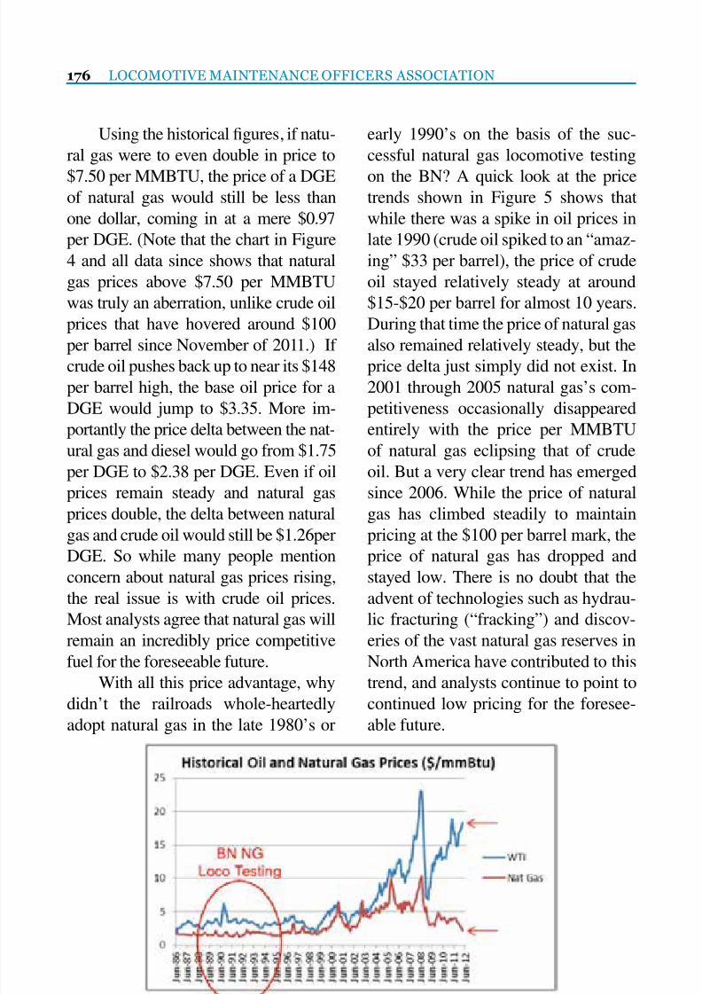
7/25/2019 Lmoa2013 Book Web Final
http://slidepdf.com/reader/full/lmoa2013-book-web-final 178/252
176 LOCOMOTIVE MAINTENANCE OFFICERS ASSOCIATION
Using the historical gures, if natu-
ral gas were to even double in price to
$7.50 per MMBTU, the price of a DGEof natural gas would still be less than
one dollar, coming in at a mere $0.97
per DGE. (Note that the chart in Figure
4 and all data since shows that natural
gas prices above $7.50 per MMBTU
was truly an aberration, unlike crude oil
prices that have hovered around $100
per barrel since November of 2011.) Ifcrude oil pushes back up to near its $148
per barrel high, the base oil price for a
DGE would jump to $3.35. More im-
portantly the price delta between the nat-
ural gas and diesel would go from $1.75
per DGE to $2.38 per DGE. Even if oil
prices remain steady and natural gas
prices double, the delta between naturalgas and crude oil would still be $1.26per
DGE. So while many people mention
concern about natural gas prices rising,
the real issue is with crude oil prices.
Most analysts agree that natural gas will
remain an incredibly price competitive
fuel for the foreseeable future.
With all this price advantage, why
didn’t the railroads whole-heartedly
adopt natural gas in the late 1980’s or
early 1990’s on the basis of the suc-
cessful natural gas locomotive testing
on the BN? A quick look at the pricetrends shown in Figure 5 shows that
while there was a spike in oil prices in
late 1990 (crude oil spiked to an “amaz-
ing” $33 per barrel), the price of crude
oil stayed relatively steady at around
$15-$20 per barrel for almost 10 years.
During that time the price of natural gas
also remained relatively steady, but theprice delta just simply did not exist. In
2001 through 2005 natural gas’s com-
petitiveness occasionally disappeared
entirely with the price per MMBTU
of natural gas eclipsing that of crude
oil. But a very clear trend has emerged
since 2006. While the price of natural
gas has climbed steadily to maintainpricing at the $100 per barrel mark, the
price of natural gas has dropped and
stayed low. There is no doubt that the
advent of technologies such as hydrau-
lic fracturing (“fracking”) and discov-
eries of the vast natural gas reserves in
North America have contributed to this
trend, and analysts continue to point to
continued low pricing for the foresee-
able future.
Figure 5 – Historical Oil and Natural Gas Prices During Railroad Locomotive Testing

7/25/2019 Lmoa2013 Book Web Final
http://slidepdf.com/reader/full/lmoa2013-book-web-final 179/252
Dynamic Braking Resistors
& Systems
(Locomotives and Off-Highway Trucks)
Load Banks(Including Locomotive testing)
Electric Heaters(30kW up to 180kW)
Neutral Grounding Resistors
A custom build solution for
any Power Resistor needs
MOSEBACH MANUFACTURING COMPANY
1417 McLaughlin Run Road • Pittsburgh, PA 15241-3103 USA
T: 412-220-0200 • F: 412-220-0236
www.mosebachresistors.com

7/25/2019 Lmoa2013 Book Web Final
http://slidepdf.com/reader/full/lmoa2013-book-web-final 180/252
178 LOCOMOTIVE MAINTENANCE OFFICERS ASSOCIATION
A nal point to note that is of po-
tential advantage to the large scale eet
operations of railroads is a willingnessfor gas suppliers to lock in long-term
contracts. Because of the price compe-
tition in the market natural gas suppli-
ers have been willing to lock in rates
for ve and even ten year contracts.
These are contract terms that were pre-
viously unheard of.
Locomotive Criteria Emissions
While economics are an internal
force that can certainly move a railroad
to adopt natural gas, the fact remains
that external forces, particularly in
regard to EPA regulated criteria emis-
sions (NOx, PM, HC, CO) have been
the driving force in new locomotiveengine technologies. New locomotives
must meet current Tier 3 requirements
and upcoming Tier 4 requirements, and
if that means that locomotive manufac-
turers must sunset some age-old loco-
motive engine designs, or add complex
aftertreatment devices that increase
both capital and operational expenses,
this is the price that must be paid to
meet EPA regulations. So in this regard
it is encouraging to note that natural
gas powered locomotives can have two
benets in regard to these emissions.
The rst is that the cost savings for
the natural gas fuel itself can offset the
incremental cost of new engine tech-
nologies and/or aftertreatment devices.For example, if a line haul locomotive
cost an extra $1M for a Tier 4 locomo-
tive vs. a Tier 3 locomotive, just a cost
savings of 50 cents or $1 per DGE of
fuel consumed could pay for the extra
locomotive cost in less than ve years.
Over the life of the locomotive the lo-
comotive could potentially pay for it-
self in fuel savings alone.This savings can also apply to
switcher locomotives which have been
consistently looked at as more of a cost
of doing business than a revenue gen-
erator. With modern multi-genset loco-
motives or ECO repowers costing well
over $1M each, railroads have been
hesitant to spend these huge sums onswitcher eets. But railroads have also
recognized the need to replace their
aging switchers with clean locomo-
tives that benet the local environment,
especially around urban rail yards.
Natural gas can have a huge impact on
leveling the cost playing eld for new,
ultra-clean, switcher locomotives. Ithas been estimated that by moving to
a modern fuel efcient Tier 3 or Tier 4
locomotive engine, and replacing just
60% of the diesel fuel used with natural
gas (a dual fuel locomotive), an ultra-
clean locomotive could pay for itself in
10-15 years. For the rst time in recent
history natural gas holds the potential
to make new switcher locomotives cost
effective and actually return an ROI to
the railroads purchasing them.
The second benet from natural
gas locomotives is a denite positive
impact on the criteria emissions pro-
duced from a straight natural gas or
even dual fuel (diesel and natural gas
combined) diesel engine. Studies haveshown that the use of natural gas can
reduce NOx levels. Some natural gas
engines have publicized as much as a
10-15% drop in NOx emissions. While
these reduction levels will not neces-
sarily move an engine from one EPA

7/25/2019 Lmoa2013 Book Web Final
http://slidepdf.com/reader/full/lmoa2013-book-web-final 181/252
NEW TECHNOLOGIES 179
Tier level to the next (e.g. natural gas
fuel will not necessarily clean up a Tier
3 locomotive engine to the point thatit meets EPA Tier 4 levels), the addi-
tional NOx reduction could benet a
railroad’s or community’s overall NOx
reduction plans. And since a railroad
can quantify the savings on natural
gas, those economic savings and emis-
sions reductions may justify a railroad
moving to a cleaner locomotive level,such as moving to Tier 3 locomotives
instead of a Tier 0+ retrot, or Tier 4
instead of Tier 3. In this way a railroad
can maximize its NOx reduction while
minimizing cost.
When it comes to PM emissions,
natural gas is denitely a game chang-
er. A diesel engine re-designed to runon 100% natural gas will reduce PM
emissions by about 85% just by switch-
ing from diesel fuel to natural gas.
These percentages of reduction can be
extrapolated with dual fuel natural gas
engines as well. To illustrate, let’s say
we have a Tier 3 locomotive engine
without a DPF system that produces
0.07 gr/bhp-hr of PM, well below the
0.10 gr/bhp-hr required to meet EPA
Tier 3 emissions. If this engine were
to run on a 50/50 mixture of diesel and
natural gas, a rough estimate would be
a 42.5% reduction in PM emissions.
PM reductions would drop from 0.07
gr/bhp-hr to 0.04 gr-bhp/hr. Our Tier
3 locomotive engine with no PM af-tertreatment is suddenly coming very
close to EPA Tier 4 PM levels of 0.03
gr/bhp-hr! And we are reducing our
PM while saving money on fuel.
Another aspect of PM management
with natural gas is the size requirement
of a DPF system for a natural gas lo-
comotive. If a DPF system is added, a
smaller unit can potentially be tted onthe locomotive. With internal real estate
on locomotives becoming more of an
issue, the use of a smaller DPF may be
a critical factor to moving a locomotive
from some PM emissions to virtually
zero PM emissions. Or if a larger size
DPF is used, the number of regenerates
the unit must go through to purge itselfof built up PM can be reduced. This
also means that the time between clean-
ing ash out of the PM system could be
reduced. Lowered maintenance equals
lower operational costs. Even replace-
ment intervals on the DPF lter could be
stretched, which also lowers locomotive
operational costs.
Locomotive GHG Emissions
Another area of emissions that
benets from natural gas is greenhouse
gas emissions (GHG). GHG emissions
have been the topic of much debate, and
we all recognize that trains, due to their
inherent efciency in moving a ton of
freight on a low amount of fuel, are
certainly environmentally friendly. But
when it comes to GHG gas emissions,
it is not simply the overall amount of
GHG emissions that is looked at by the
regulatory agencies, but the amount of
GHG produced from a given amount
of fuel. As such, upcoming GHG re-
duction requirements that it appearswill be forthcoming from the EPA will
push the transportation sector towards
the adoption of more GHG emissions
friendly fuels. This is another area
where natural gas has an advantage
over diesel fuel.

7/25/2019 Lmoa2013 Book Web Final
http://slidepdf.com/reader/full/lmoa2013-book-web-final 182/252

7/25/2019 Lmoa2013 Book Web Final
http://slidepdf.com/reader/full/lmoa2013-book-web-final 183/252
NEW TECHNOLOGIES 181
Based on the current California
LCFS, CNG fuel produces ~32% lower
GHG emissions than diesel. Depend-ing on the efciency of the liquefac-
tion process (80% or 90%) the GHG
reduction for LNG ranges from about
16.9% to 27.6%. These percentages of
reductions are quite signicant in terms
of GHG reduction goals set forth by
many governmental and environmental
groups.Even if a locomotive is using a
dual fuel engine (which runs on a com-
bination of natural gas and diesel),
signicant GHG reduction can still be
attained. It should also be noted that
the use of a dual fuel engine does not
change the engine’s ability to utilize a
biodiesel blend to reduce GHG emis-
sions even further. For example, if a
diesel engine was originally designedto use a B20 biodiesel blend (20% bio-
diesel and 80% petroleum diesel), the
dual version should still be able to use
a B20 biodiesel blend. Thus, if a dual
fuel engine used a 60/40 mix of CNG
and diesel fuel, the 60% replacement
with CNG would drop GHG emis-
sions by 32% for that volume of fuel,and the 40% biodiesel remaining could
drop GHG by emissions by anywhere
from 3.3% to 17.6%. The combined
GHG reduction for a natural gas dual
fuel locomotive could thus be as high
as 26.2%. (See Figure 7)
Figure 7 – Individual and Combined Fuel GHG Reduction

7/25/2019 Lmoa2013 Book Web Final
http://slidepdf.com/reader/full/lmoa2013-book-web-final 184/252
182 LOCOMOTIVE MAINTENANCE OFFICERS ASSOCIATION
Fuel Storage Options
One of the biggest challenges pre-
sented to the adoption of natural gas ishow to store the fuel. Since natural gas
in its raw form is a gas and not a liq-
uid, the fuel cannot be usably stored in
its native state on a locomotive and/or
tender. It must be either compressed or
liqueed.
Before discussing these storage
technologies, it should be noted thatmany natural gas engines, both straight
natural gas and dual fuel, are ambiva-
lent to the way in which the natural gas
is stored. This is because the natural
gas being introduced into the engine is
in a gaseous state. So if the gas comes
from a high pressure CNG tank, it sim-
ply needs to be regulated down to thestandard low injection pressure, usu-
ally around 120psi-150psi. If the fuel
is stored as LNG, it goes through a
vaporizer to convert it from liquid to
gas and is then regulated to the low
pressure needed by the engine. So if
the vaporizer is part of the fuel tank
system, the same natural gas locomo-
tive could use CNG or LNG fuel inter-
changeably. Some high pressure direct
injection (HPDI) systems require LNG,
but this is a requirement of the specic
fuel injection technology, not natural
gas engines as a whole. It should also
be noted that because the BTU content
of natural gas from LNG or CNG is
basically the same, no perceivable dif-ference in performance would be noted
between an engine running on CNG or
LNG. (Technically natural gas from
CNG may have a slightly higher BTU
value because it may contain up to 20%
propane, ethane, and butane, which are
usually removed to create “dry gas” for
liquefaction.)
When compressed, the gas isstored under high pressure in a stor-
age cylinder. These cylinders can be
made of metal (aluminum or steel) or
a composite material and then wrapped
with a steel or composite wrapping.
Up until recently most on-road CNG
systems were compressed to 3,600psi
(250 barg). Because of the low BTUcontent per cubic foot of 3,600psi CNG
compared to diesel, many people felt
that this precluded CNG from being a
viable locomotive fuel. But when used
for powering locomotives in switching,
local, or branch line service, 3,600psi
tanks can be viable, especially on dual
fuel powered locomotives.LNG has the highest per volume
BTU content of any natural gas stor-
age technologies. This is because LNG
is a true liquid state of natural gas. The
BTU content of a gallon of LNG is ap-
proximately 59% that of a gallon of
diesel. When used in a dual fuel engine,
an LNG fueled locomotive having an
average 70% natural gas for diesel sub-
stitution rate, can provide about 71%
of the range of straight diesel. Consid-
ering that the fuel cost savings for a
single line haul locomotive in long dis-
tance service can be hundreds of thou-
sands of dollars per year, many rail-
roads and locomotive manufacturers
are giving LNG serious consideration,even if it involves storage in separate
fuel tenders.
There are some additional issues
with LNG that must be taken into
consideration. One is the state of the
fuel itself. LNG is an extremely cold

7/25/2019 Lmoa2013 Book Web Final
http://slidepdf.com/reader/full/lmoa2013-book-web-final 185/252
NEW TECHNOLOGIES 183
cryogenic liquid, which means that its
temperature is well below the freez-
ing point of water. The temperature ofLNG is -260 degrees F (-162 degrees
C). In order to keep the liquid this cold,
it must be stored in vacuum insulated
cryogenic tanks. And special handling
is a must, since contact of liquids this
cold with any part of a human body will
cause immediate frost bite and severe
tissue damage. Since there will alwaysbe some pressure in an LNG tank due
to some “boil off” of the LNG in the
tank, a crack in an LNG tank will result
in a low pressure “spray” of extreme-
ly cold liquid. So while the escape of
the gas itself may not be hazardous to
personnel, contact with the super-cold
liquid being expelled a potentially longdistance can be.
The cost of LNG can also be sig-
nicantly higher than CNG. This is be-
cause the LNG requires more complex
liquefaction equipment that must be
suitable for cryogenic conditions and
there is an additional energy cost as-
sociated with liquefaction vs. straight
compression. LNG can cost $0.75 to
$1.00 more per DGE than CNG, and
this extra cost must be weighed against
the costs associated with shorter range
or additional fueling stops associated
with a CNG fueled locomotive.
A new natural gas storage option
that is already being adapted to on-road
vehicles is high pressure CNG. Highpressure CNG utilizes high pressure
wrapped tanks, usually of a Type 4
composite design. These tanks can han-
dle pressures well in excess of 5,000psi.
5,000psi high pressure CNG tanks
have been used for stationary storage
for some time, and are now becom-
ing available for mobile use. In fact,many of these same design tanks are
already used for hydrogen fueled ve-
hicles where pressures can range from
7,000psi on up to almost 10,000psi. So
these high pressure tanks are already
proven. Moving to 5,000psi CNG tanks
moves the volumetric energy content
of CNG vs. diesel from 25% to around38%. Another way to look at this is
that 5,000psi CNG is suddenly 64%
the energy storage volume of LNG, vs.
a paltry 42% for 3,600psi CNG. This
can be a real game changer in the deci-
sion making process of whether to use
CG or LNG in many shorter distance
applications. New fueling station tech-
nology for 5,000psi CNG also uses less
energy than previous 3,600psi fueling
stations and keeps the CNG cylinders
cooler during refueling, thus making
it possible to consistently ll the CNG
tanks to maximum capacity while also
generating the least amount of heat
build-up.

7/25/2019 Lmoa2013 Book Web Final
http://slidepdf.com/reader/full/lmoa2013-book-web-final 186/252
184 LOCOMOTIVE MAINTENANCE OFFICERS ASSOCIATION
Natural Gas Safety/Risks
As with the adoption of any new
technology, concerns always arise re-
garding the safety of the technology.
This also applies to adopting new fuels
such as natural gas.
While the railroads have only ex-
perimented with natural gas locomo-
tives, natural gas vehicles using both
CNG and LNG fuel storage are nothing
new. These vehicles have been in use
transporting people and freight for de-
cades. In fact, one of the most common
applications of CNG fueled vehicle is
in transit buses. These buses transportmillions of passengers each year. Yet
we simply do not hear of mass deaths
due to CNG fueled buses exploding or
otherwise causing harm. Add to this the
estimated 15 million natural gas fueled
cars and trucks worldwide, and it be-
comes very clear that natural gas is an
inherently safe vehicle fuel.
One reason for the outstanding
safety record of natural gas fueled vehi-
cles is mature safety standards that have
been in place and evolved over the de-
cades of natural gas use. This includes
not only safety standards for the ve-
hicles and engine systems themselves,
but also stringent standards for fuel
storage systems (both stationary and
mobile), handling, and refueling. In the
United States these standards primar-
ily fall under the auspices of the U.S.
Department of Transportation, whichregulates not only on-road vehicles, but
railroads as well through the Federal
Railroad Administration (FRA). While
there are no specic regulations in place
by the FRA for natural gas locomo-
tives, many of the regulations already
Figure 8 – Fuel Storage Options

7/25/2019 Lmoa2013 Book Web Final
http://slidepdf.com/reader/full/lmoa2013-book-web-final 187/252
NEW TECHNOLOGIES 185
in place cover aspects of natural gas
locomotives. The US DOT has a very
robust set of standards and guidelinesas part of the Federal Motor Vehicle
Safety Standards (US DOT FMVSS).
In addition to these federal regulations,
the National Fire Protection Associa-
tion (NFPA) has published codes and
standards under NFPA 52, the Vehicu-
lar Gaseous Fuel System Code. These
requirements are very stringent and areperfectly adaptable to locomotive ap-
plications. Finally, there are the internal
natural gas vehicle industry standards
known as NGV Codes. In many cases,
these NGV codes go above and beyond
what is required by DOT and NFPA.
So much so in fact, that many other
countries outside the U.S. have adoptedthese NGV Codes into their natural gas
vehicle requirements.
Another critical aspect is the am-
mability and characteristics of natural
gas itself, especially as compared to
diesel fuel. Figure 9 shows the am-
mability and risks associated with
methane, the primary component of
natural gas, compared to diesel fuel.
Natural gas has a very limited range
of ammability. Natural gas is am-
mable only within about a 5-15% gas-
to-air mixture. And, it has a very highignition temperature. The high ignition
temperature and the limited amma-
bility range make accidental ignition
or combustion unlikely. Natural gas is
lighter than air. This means that gener-
ally when natural gas is accidentally
released into the outside air it will ride
and vent harmlessly into the atmo-sphere, thus dissipating from the site
of a leak. When a gas-and-air mixture
within the ammable range collects in
a conned space, it can accidentally ig-
nite upon a source of ignition. But this
ignition source must be very high tem-
perature. And when the natural gas ig-
nites, the re is limited to the gas in thearea where the natural gas and air mix
is within the ammability limit. Once
it hits the higher natural gas concentra-
tion point the ame will discontinue
propagation, unlike a major diesel spill
which will continue to burn for hours as
the liquid fuel pool continues to burn.
For example, one issue that has
been raised is whether the exhaust man-
ifolds, situated high up in the carbody
Figure 9 – Natural Gas Safety/Risks

7/25/2019 Lmoa2013 Book Web Final
http://slidepdf.com/reader/full/lmoa2013-book-web-final 188/252
186 LOCOMOTIVE MAINTENANCE OFFICERS ASSOCIATION
of a locomotive, would be a potential
ignition source for any lighter-than-air
natural gas that might accumulate there.Clearly the exhaust manifold/stacks
constitute a heat source, but not really
an ignition heat source for natural gas.
The autoignition temperature for diesel
fuel is 210 degrees C (410 degrees F).
The autoignition temperature for natu-
ral gas is almost three times that, at 580
degrees C (1,076 degrees F). Autoig-nition temperature refers to the lowest
temperature at which a substance will
spontaneously ignite without an exter-
nal source of ignition such as a spark
or ame. So the exhaust system under
the hood of a locomotive is considered
a potential autoignition source.
According to a verication re-port published in 2005 by the EPA,
the exhaust temperature of a 3,000
HP turbocharged EMD 16-645E3 en-
gine is about 201 degrees F at high
idle (223 degrees F at low idle) and
goes up to a high of 732 degrees F
at Notch 6 (Notch 8 is actually only
720 degrees F). So diesel fuel will
ignite if sprayed on the exhaust mani-
fold since the autoignition tempera-
ture for diesel is only 410 degrees F,
well below the potential 732 degrees
F manifold temperature. But even at
the highest exhaust temperatures the
EMD engine exhaust manifold would
still be almost 350 degrees F below
the autoignition temperature for nat-ural gas. So natural gas is actually
much safer from this standpoint than
diesel fuel.
The bottom line is that there really
is no consistent heat source under the
hood of a locomotive for ignition of
natural gas. You would need to have an
open ame or consistent spark source
or a hot engine component producinga temperature of 1,076 degrees F or
above to ignite the natural gas. This is
just one example why natural gas can
be safely used in locomotives.
Diesel and Natural Gas Engine
Technologies
For railroads seeking to run loco-motives there is a wide range of engine
technologies that can run on straight
diesel fuel, dual fuel (diesel and natural
gas, or straight natural gas. As the table
in Figure 10 shows, these three overall
engine options cover a wide range of
natural gas substitution, from no sub-
stitution (straight diesel) all the way upto 100% natural gas with no diesel fuel
needed at all.
Our baseline is a 100% straight
diesel engine. This is our stock off-the-
shelf engine from any major locomo-
tive manufacturer or OEM supplier of
locomotive engines. These are tried
and true engines, and we know what to
expect from these engines.
The highest substitution rate of
natural gas (100%) requires major
conversion of the engines from their
original diesel conguration. Most no-
tably, the compression ratio is lowered
dramatically, and thus the horsepower
output is signicantly decreased. For
example, the four LNG locomotivesused until recently by the BNSF were
rated at only 1,200 HP, despite the fact
that the stock V-16 diesel engine pro-
duced between 1,600 HP and 2,200 HP
depending on conguration. A horse-
power de-rate of between 25% to 40%

7/25/2019 Lmoa2013 Book Web Final
http://slidepdf.com/reader/full/lmoa2013-book-web-final 189/252
NEW TECHNOLOGIES 187
Figure 10 – Diesel and Natural Gas Engine Technologies – Fuel Mix
is not uncommon with pure natural gas
versions of diesel engines. These en-
gines also depend on a spark plug to ig-
nite the natural gas, so the engines must
have modications made to the heads
as well. Some straight natural gas en-gines also suffer from poor or slower
transient response times, and in some
locomotive applications, such as kick-
ing cars, this can be a denite problem.
In between these two extremes
is the dual fuel engine, which runs on
a mix of diesel fuel and natural gas.
These engines may or may not require
modication to the base diesel engine.
The key to a dual fuel engine is that a
certain percentage of the air introduced
into the cylinder contains natural gas.
When the diesel fuel is introduced into
the cylinder, less is needed to produce
the same amount of energy since the
natural gas in the air mix contributes
the combustion energy output. The
key is that the natural gas ow into
the air mix must be metered and moni-
tored so as to control the amount of
diesel fuel injected into the cylinder,thus maintaining a given amount of
horsepower at a given RPM. There are
also issues of engine knock not nor-
mally associated with a diesel engine
that must be monitored and controlled.
Another advantage to many dual fuel
engine systems is that if the locomo-
tive runs out of natural gas or the natu-
ral gas fuel supply must be shut down
due to a problem with natural gas dos-
ing/injection system, the engine will
continue to run on straight diesel. For
many railroads this “fallback” option
is an important criterion for consider-
ing a switch to natural gas.

7/25/2019 Lmoa2013 Book Web Final
http://slidepdf.com/reader/full/lmoa2013-book-web-final 190/252
188 LOCOMOTIVE MAINTENANCE OFFICERS ASSOCIATION
Figure 11 – Natural Gas Engines – Dual Fuel Technologies
Within the dual fuel engine tech-
nologies there is a range of ways to in-
troduce natural gas to the engine. Each
of these technologies has its own pros
and cons and must be taken into ac-
count when choosing a dual fuel sys-tem. Figure 11 outlines the high level
breakdown of these systems.
The rst and simplest system to
convert a diesel engine to dual fuel
involves a single point of gas injec-
tion. Sometimes known as fumiga-
tion, the gas manifold can be placed
virtually anywhere along the air intake
system. Some single point manifold
systems place the gas inlet before the
turbocharger. This means, however,
that the gas/air mixture is actually go-
ing through the turbocharger and be-
ing heated and compressed. While the
heated air/fuel mix coming out of the
turbocharger is nowhere near the 1,076
degrees F autoignition point of natural
gas (typical turbocharger outlet tem-
peratures are around 400 degrees F)
the introduction of natural gas before
the turbocharger has been safely donefor years. But some customers may
prefer the injection post turbocharger,
and there are systems that are designed
for injection of the gas after the tur-
bocharger. Depending on the engine
design, this natural gas injection can
even be done post-intercooler or charge
air cooler (CAC), thus taking advan-
tage of a more stable air temperature.
Many larger locomotive engines have
the turbocharger and intercooler system
closely connected to the intake mani-
fold, so in these instances the gas injec-
tion must be placed between the turbo
and the intercooler.

7/25/2019 Lmoa2013 Book Web Final
http://slidepdf.com/reader/full/lmoa2013-book-web-final 191/252

7/25/2019 Lmoa2013 Book Web Final
http://slidepdf.com/reader/full/lmoa2013-book-web-final 192/252
190 LOCOMOTIVE MAINTENANCE OFFICERS ASSOCIATION
heart of the engine is a patented injector
with a dual-concentric needle design.
It allows for small quantities of dieselfuel and large quantities of natural gas
to be delivered at high pressure to the
combustion chamber. The natural gas
is injected at the end of the compres-
sion stroke. (Non-HPDI systems dis-
cussed earlier bring the natural gas in
with the air during the intake stroke.)
As mentioned earlier, under the pres-sures found in the combustion chamber
of a normal diesel engine, natural gas
requires a higher ignition temperature
than diesel. To assist with ignition, a
small amount of diesel fuel is injected
into the engine cylinder followed by
the main natural gas fuel injection. The
diesel acts as a pilot, rapidly ignitingthe hot combustion products, and thus
the natural gas. HPDI replaces approxi-
mately 95% of the diesel fuel (by en-
ergy) with natural gas.
Because the natural gas is actually
injected after the diesel fuel is injected
and begins to ignite, very high pres-
sures in the fuel lines are required. For
this and other reasons some manufac-
turers, such as Westport, consider their
systems to be designed only for use
with LNG. So a customer of a particu-
lar HPDI system may be required to
choose a particular fuel (i.e. LNG over
CNG) just simply to support that natu-
ral gas engine technology, and not be-
cause the economics or range require-ments require it.
The engine technologies outlined
are just a broad overview of existing and
upcoming technologies for locomotives.
As this paper was being prepared at least
one company has stated that they have
a fuel delivery system that will allow
CNG to be used with HPDI systems.
Some of these new technologies may al-low an increase in fuel substitution rates
that blur the lines even further of which
engine technology is best suited for lo-
comotive applications.
CNG and LNG Fuel Storage – On
Board or Tender Cars
As so many times happens in all in-dustries (railroads included), we many
times come full circle in technologies
applied to our business. For example,
early steam locomotives required a
tender to store fuel and water for any
long range operation. In fact, very few
operations had the luxury of dispens-
ing with the tender and storing all thefuel and water on board the locomotive
itself. The advent of the diesel locomo-
tive with its on-board fuel tanks and no
need for water was considered by many
a huge advance over the steam locomo-
tive. Today’s modern high-horsepower
locomotives carry 5,000 or 6,000 gal-
lons of diesel fuel, reducing even trans-
continental trips to a minimum number
of fueling stops.
With the switch to natural gas fuel,
interest has been renewed in tender
cars, due to the lower BTU content of
CNG and LNG compared to the same
volume of diesel fuel. As a result the
need for fuel tenders, FRA and AAR
have both put together work groupsmade up of railroads, suppliers, and in-
dustry experts, to set the standards for
the new generation of natural gas loco-
motives and tenders.
In October 2012 the FRA con-
vened a workshop titled “Natural Gas

7/25/2019 Lmoa2013 Book Web Final
http://slidepdf.com/reader/full/lmoa2013-book-web-final 193/252
NEW TECHNOLOGIES 191
Locomotive Technology” at Argonne
National Laboratory in Lemont, IL. It
was organized by the FRA to developa roadmap for the use of natural gas in
rail applications. The workshop was
attended by 55 participants spanning
railroads, locomotive manufacturers,
OEM suppliers, and research and fed-
eral organizations.
This group is now known as the
Natural Gas Locomotive Research TaskForce. The task force continues to meet
to look at all aspects of locomotive and
tender safety and technology. In addi-
tion to the FRA group, the AAR has cre-
ated its own working group. Known as
the Natural Gas Fuel Tender Technical
Advisory Group (AAR NGFT TAG)
this advisory group is looking primarilyat locomotive fuel tender needs for line
haul locomotives, including standards
and safety for the delivery of the fuel
(gaseous or liqueed) across connec-
tions from the tender to the locomotive.
It is expected that these same standards
and recommendations would be used
for any interface between a natural gas
locomotive and a separate natural gas
fuel source, such as a slug that might be
equipped with LNG or CNG fuel tanks.
One key aspect of an LNG ten-
der is the location of the vaporizer that
converts the LNG to gas. These vapor-
izers require large amounts of energy to
convert the extremely cold liquid to a
gaseous state. A diesel locomotive hasa lot of waste heat that it must dispose
of through the exhaust and radiator sys-
tem. If this waste heat can be used to
vaporize the LNG, that energy is actu-
ally being used more efciently. The
challenge is where to locate the vapor-
izer. If it is put on the tender car, then
the hot coolant from the locomotive’s
radiator circuit must be piped acrossbetween the locomotive and tender.
And once the LNG is vaporized, it
must be decided whether the gas that
is piped back to the locomotive is high
pressure gas (5,000 psi) or low pres-
sure gas (125-150 psi). If the vaporizer
is placed on the locomotive, there is no
need to move high temperature enginecoolant across to the LNG tender, but
we must nd a place on the locomotive
to put the vaporizer. This is no easy task
because of the limited real estate on to-
day’s Tier 3 and upcoming Tier 4 lo-
comotives! (One suggestion was to re-
duce the size of the diesel fuel tank and
use that space for the vaporizer. Since ahigh percentage of the fuel for the loco-
motive is coming from the tender, the
locomotive would not require the same
amount of diesel fuel to get between
existing fueling stops anyway.) If the
vaporizer is on the locomotive then ex-
tremely cold cryogenic LNG must be
passed through a connection between
the tender and locomotive. This would
require higher power cryogenic pumps
and insulated cryogenic lines between
the locomotive and tender. The AAR
NGFT TAG continues to look at all
these nuances of fuel tenders.
Another interesting caveat of the
use of a fuel tender is its status as a
hazardous materials car. If fuel isstored on board a locomotive it comes
under the rules applying to fuel tanks,
and thus a locomotive is not consid-
ered a hazardous materials car even
if it is carrying thousands of gallons
of diesel fuel. As soon as the fuel is

7/25/2019 Lmoa2013 Book Web Final
http://slidepdf.com/reader/full/lmoa2013-book-web-final 194/252
192 LOCOMOTIVE MAINTENANCE OFFICERS ASSOCIATION
moved to a tender car it now falls un-
der the jurisdiction of the HAZMAT
rules governed by additional agenciesbeyond just the FRA. The Pipeline
and Hazardous Materials Safety Ad-
ministration (PHMSA) develops and
maintains the regulations on the trans-
portation of hazardous materials by
rail, contained in Title 49 of the Code
of Federal Regulations Parts 100-185.
The FRA works with PHMSA to en-force the transportation of hazardous
material by rail. Currently, natural
gas cannot be transported by rail un-
less the rail carrier obtains a Special
Permit. However, a Special Permit is
not required for the use of natural gas
as fuel for the locomotive but the lo-
comotive being classied as a vehiclethat carries natural gas or any other
material being used to fuel attending
locomotives is subject to FRA’s statu-
tory and regulatory authority related to
locomotives contained in the Federal
railroad safety statutes.
This brings up the option of storing
the natural gas fuel on board the loco-
motive itself. Depending on the design
of locomotive itself, it is entirely pos-
sible to place CNG or LNG tanks on
a locomotive. While LNG would once
again seem to be the natural gas fuel of
choice, recent studies on locomotive
duty cycles, dual fuel engine efciency,
and on-board space available for the
fuel tank(s), has shown that CNG is avery viable fuel for switcher locomo-
tives using as much as 50,000 to 60,000
gallons of fuel per year. On larger road
switcher locomotives used for trans-
fer or local service, the additional fuel
space available on a longer frame lo-
comotive makes on-board CNG viable
for these environments as well. By put-
ting the natural gas fuel on board, theissues of moving fuel between a tender
and the locomotive, adding the ad-
ditional tender to the locomotive con-
sist, and turning a locomotive-tender
combination at the end of a line (to
keep the tender from leading a single
locomotive consist) are all eliminated.
Additionally, whereas LNG may not beeconomical in terms of cost savings on
a lower fuel consumption locomotive,
the extra $0.75 to $1.00 per DGE sav-
ings of CNG over LNG could make the
difference between staying with current
diesel locomotives or moving to a natu-
ral gas alternative. One recent study
by a major switching railroad suggestsa savings of as much as $100,000 per
year by replacing older Tier 0 or Tier
0+ 1,500 HP switchers with new Tier
3 dual fuel CNG powered locomotives.
With savings of this magnitude it is
hard for a railroad not to consider natu-
ral gas as a fuel alternative.
Conclusion
There is little doubt that natural
gas is here to stay. The Energy Infor-
mation Agency (EIA) estimates that the
supply of natural gas (NG) in America
will last over 100 years thanks to frack-
ing of shale rocks. Considering the cost
differential between natural gas and
diesel and that this differential does notappear to be collapsing in the foresee-
able future, there is signicant fuel sav-
ings opportunity in using natural gas in
locomotive engines.
This white paper is not intended
to present every possible natural en-

7/25/2019 Lmoa2013 Book Web Final
http://slidepdf.com/reader/full/lmoa2013-book-web-final 195/252
NEW TECHNOLOGIES 193
gine or locomotive technology. New
advancements are being made every
day in regard to natural gas storagesystems, dual fuel and straight natural
gas engine technologies, and natural
gas exploration and drilling techniques.
As these natural gas technologies and
locomotives are developed, it is expect-
ed that a number of new white papers
will be forthcoming from not only the
LMOA New Technologies Committee,but other LMOA committees as well.
For many of us who work with
locomotives every day, the steam to
diesel transition era is something that
we never actually experienced. While
a complete transition from diesel to
natural gas may never materialize, thenew natural gas technologies being pre-
sented for locomotives is certainly no
less exciting in its economic, environ-
mental, and even operational potential.
Who knows, maybe in 2036 one of the
rst successful new technology natural
gas locomotives of today will end up
in the same museum next to the earlyPlymouth propane locomotive of 1936.
That would make quite an interest-
ing 100 year anniversary celebration,
wouldn’t it?

7/25/2019 Lmoa2013 Book Web Final
http://slidepdf.com/reader/full/lmoa2013-book-web-final 196/252
194 LOCOMOTIVE MAINTENANCE OFFICERS ASSOCIATION
Your locomotive is miles away
when it develops trouble or is running
low on fuel. How would you know that
there is a potential problem? Wouldn’t
it be helpful if your loco could let you
know that it is low on fuel or that an
engine parameter is out of range? This
is where the world of remote diagnos-
tics and fuel monitoring is becoming
the hero.
There are several options out theretoday and here we plan to just touch on
a couple of those options and what they
may be able to accomplish for the rail-
road today.
The goal? Locomotive reporting
for improved on-time performance and
locomotive reliability.
One of the benets of remote mon-itoring is the enhancement of reliability
since with back ofce storage of loco-
motive alarms and records this informa-
tion is readily available at a moment’s
notice. Performance improvements
can be made with the real-time opera-
tional status of the roads locomotive.
With this information, shop dwell timecan be reduced by being able to pre-
emptively take care of problems before
they can shut you down. Road failures
are reduced, keeping the operation run-
ning on time. Fuel levels and consump-
tion can be monitored as well. With this
information the chances of locomotives
running out of fuel on the main line can
be reduced. With this remote informa-
tion available in real-time, dispatch can
decide whether a consist needs to go to
the fuel rack or if it can be directly tied
on another train without refueling.
Remote monitoring comes in vari-
ous levels of capabilities:
The rst level, or Basic, gives
minimal feedback. Items include GPSlocation, locomotive speed, direction,
and fuel level.
The next level would incorporate
these basics and a few others. Event
recorder logs can be remotely acquired
for review when needed. The Locomo-
tive Control Computer can pass alarms
indicating faults on the road and some-times data packs as well. Another up-
and-coming type of monitoring is the
video monitor. With the video monitor
both stills and video clips can be down-
loaded remotely.
Ultimately, all these items can be
monitored, but with a couple of more
benets. Back ofce data services canstore historical data for tracking when
and where faults occurred and if they
are repeating. With this historical data
performance reports can be compiled
on the eet identifying bad actors and
units that need attention. Also, some
Remote Monitoring of Locomotive Systems
Prepared by:
Joe Whitmer
Southern Region Field Service Manager
MotivePower, Inc.

7/25/2019 Lmoa2013 Book Web Final
http://slidepdf.com/reader/full/lmoa2013-book-web-final 197/252

7/25/2019 Lmoa2013 Book Web Final
http://slidepdf.com/reader/full/lmoa2013-book-web-final 198/252
196 LOCOMOTIVE MAINTENANCE OFFICERS ASSOCIATION
plans from manufacturers of remote
monitoring offer Help Desk services to
get units over the road by assisting thecrew on the unit.
System architecture can vary by
vendor, but the basic layout is similar to
Figure 1 below. The remote monitoring
computer communicates with the vari-
ous on-board systems gathering data.
As shown in Figure 1 some systems
such as Electronic Air Brake may feedinto the Locomotive Control Computer
and this information is then passed to
the remote monitoring system. The
remote monitoring computer will then
pass this data on to its database using
a few possible methods. These meth-
ods may include 802.11, cellular, and
in some cases satellite. Cellular is usedfor the bulk of the communication on
most systems with the extensive cel-
lular network most readily available. It
can however have its dark spots and if
this is the method of choice the system
will need to store data until the next ac-cess to a cell is achieved.
Local data radio using 802.11 is
also very popular, but is limited by
distance. Most applications of this are
installed at yard locations. As with
cellular, with this protocol while the
locomotive is out of communication
range data will need to be stored anddownloaded upon arrival. The most
costly method of course is satellite data
communication. This method can be
limited in bandwidth and a clear view
of the sky is required for reliable con-
nection. The downside to most of these
though is if a locomotive is in dark
territory instantaneous downloads ofevent recorders cannot occur and will
need to wait until the locomotive has
come back to an area that has reliable
Figure 1 – Remote Monitoring Basic Layout

7/25/2019 Lmoa2013 Book Web Final
http://slidepdf.com/reader/full/lmoa2013-book-web-final 199/252
A m e r i c a n F l y e r ,
P r e-War, S tandard
G a u g e, N o.
4 6
9 2
You’ll Find PMC Gears and PinionsTurning the World’s Finest Locomotives.PMC doesn’t toy around. We make the full size ones!
Since 1920
For more information, call or visit us online.Penn Locomotive GearA Division of Penn Machine Company LLCBlairsville, PA, U.S.A.814-288-1547 ext. 211 • [email protected]
No one is better qualified to supply locomotive gears and
pinions than Penn Machine. With over 90 years of manufacturing
experience, Penn Machine makes gears and
pinions of the highest
quality for use on
locomotives from
all the leading
manufacturers. We
manufacture over 120
bull and engine gears
and 80 pinions. The most popular ones are in stock.
Our gears and pinions are made from triple alloy steel and carburized/hardened in
our in-house heat treating equipment. They provide up to 50% longer wear life than standard
heat-treated gears. And they are AAR certified and come with a 5-year limited wear warranty.
Not getting replacement gears when you need them can result in costly downtime.
That’s why delivering to meet your schedule is our way of
doing business.
exper ence, enn ac ne
pinions
qua
al
m
m
bull
and 80 pi
Our gears and pinions are made

7/25/2019 Lmoa2013 Book Web Final
http://slidepdf.com/reader/full/lmoa2013-book-web-final 200/252

7/25/2019 Lmoa2013 Book Web Final
http://slidepdf.com/reader/full/lmoa2013-book-web-final 201/252
NEW TECHNOLOGIES 197
service. So while Satellite is a possible
solution, due to expense and bandwidth
it is not very popular except in the mostextreme situations.
Hardware used on the various
systems can vary greatly. The Central
Diagnostics System (CDS) by Wabtec
uses a chassis in kind with what is
currently used for PTC systems (see
Figure 2). Actually with CDS, if the
locomotive is already equipped withPTC, the CDS processor board can use
the ‘Business Application’ slot that is
available on this unit. This may be an
option the end user can use to their ad-
vantage in not installing extra physical
hardware and taking up space.
Peaker Services offers a PLC
based system that integrates with the
engine control system. Peaker’s sys-
tem offers other exibilities since itpresents more engine related functions
than most systems currently provide.
Wi-Tronix is currently known for
its Wi-PU, which is a stand-alone pro-
cessor unit. The Wi-PU contains mul-
tiple communication ports to interface
with many different systems. This can
be advantageous to those looking to
connect to systems with a locomotiveequipped with different makes of sys-
tems that need to communicate to the
outside world.
The downside for many of these
systems though is that most to date do
not have any direct interface to discrete
signals and sensors. For most of these
applications some type of third party
interface or a PLC may be required.
Functions
By far, the most sought after goal
for remote monitoring has been and
still is GPS location. This in itself is
a great resource. Locomotives have
been ‘lost’ on railroads as long as any-
one can remember and being able to
locate them in short order has been a
savior. It can be a great help for locat-
ing the locomotive when maintenanceor crews need to locate it. Using the
GPS information from the system
plugged into the navigation GPS in
a car and the crew can nd it on that
little known siding easily.
Figure 2 – Wabtec Central Diagnostics
System (CDS)
Figure 3 – Wi-Tronix WiPU

7/25/2019 Lmoa2013 Book Web Final
http://slidepdf.com/reader/full/lmoa2013-book-web-final 202/252
198 LOCOMOTIVE MAINTENANCE OFFICERS ASSOCIATION
Figure 4 – GPS Map Location
The monitoring of fuel levels has
probably become the Number 2 item
that railroads want monitored. With
real-time fuel information dispatch-
ers can determine whether a train
that pulls into the yard needs to have
the fuel truck meet it and fuel up, or
whether the power is ready to turnand take another train directly out of
the yard. This can save a great deal of
time and labor by not having to take
the power to the barn for servicing that
may not be required. Fuel levels are
also monitored to ensure that the train
will in fact make it to the next desti-
nation without refueling in a more re-mote location.
Event recorder data has come into
its own in the last ve years. Even
DVR remote downloads have now
become main stream. Though down-
load bandwidth may limit the size of
the video download, it has become
important to have this capability. With
remote monitoring, not only can event
recorder downloads happen while on
the road, but rule infractions or inci-
dents of emergency brake applica-
tion can be immediately transmitted
to transportation department ofcials.Most all of the remote monitoring sys-
tems can be set up with custom param-
eters to notify key personnel via email
or even smart phone applications.
When remote monitoring rst
came into being many wanted to grasp
the possibilities of what information
could be gathered. At rst becauseof bandwidth and technology issues
this was limited to simple things like
location and maybe two or three dis-
crete signals. With today’s advances
most of these possibilities can be re-
alized in diagnostics of most locomo-

7/25/2019 Lmoa2013 Book Web Final
http://slidepdf.com/reader/full/lmoa2013-book-web-final 203/252
NEW TECHNOLOGIES 199
Figure 5 – Fuel consumption graph
Figure 6 – Fuel Volume Graph
Figure 7 – Real-time event recorder data

7/25/2019 Lmoa2013 Book Web Final
http://slidepdf.com/reader/full/lmoa2013-book-web-final 204/252
200 LOCOMOTIVE MAINTENANCE OFFICERS ASSOCIATION
tive systems while the unit is on the
move. Through a web-based interface
a user can readily look at the locomo-
tive status and verify that all systems
are online and functioning in real-
time. Real-time system diagnostics isbenecial to on-time performance. In
reality the locomotive can transmit pa-
rameters that are out of range which
in turn puts maintenance on alert for
when the locomotive comes in for ser-
vice so that repairs that may be needed
can actually be planned events instead
of being a surprise on arrival.When problems occur on the road
historical data can help isolate the
problem making troubleshooting sim-
pler and quicker. Graphs like Figure 11
show real-time trending while the loco-
motive is loading, giving the maintain-
er the information he needs to isolate
any issues so the locomotive can con-
tinue on without any more delay than
necessary.
With all of these features (and
those that may not have yet been dis-covered) there is of course a cost. This
breaks down into areas such as cell
phone setup and the monthly fees that
go along with them. If back ofce data
is to be maintained, how will that be
done? Will it be on-site and maintained
by the railroad? Or as many are doing,
will the railroad allow the supplyingvendor to perform the back ofce data
portion? Since these services come
with a monthly fee, on top of any moni-
toring fee, decisions have to be made.
Spare components are something else
that needs to be considered in order to
Figure 8 – DVR Snapshot

7/25/2019 Lmoa2013 Book Web Final
http://slidepdf.com/reader/full/lmoa2013-book-web-final 205/252
NEW TECHNOLOGIES 201
Figure 9 – Real-time Health Screen
Figure 10 – Remote engine screen through PSI Viewer

7/25/2019 Lmoa2013 Book Web Final
http://slidepdf.com/reader/full/lmoa2013-book-web-final 206/252
202 LOCOMOTIVE MAINTENANCE OFFICERS ASSOCIATION
keep the systems operating with allow-
ances for failure. It goes without saying
that reliability of the remote monitoring
system is the key to keeping the loco-
motives reliable. If the remote system
goes down, then the advantage has
been lost.Remote monitoring gives us long
term data collection that will assist in
historical analysis of locomotive per-
formance and event data. With these
tools individual locomotive as well as
eet performance can be determined.
Trends of failures can be more easily
seen when this data can be easily gath-ered. Real-time analysis of locomotive
troubles can be done with this data in
the hands of locomotive experts. The
future of remote monitoring includes
more and improved automated analysis
tools to keep locomotives on line.
We have only touched on what re-
mote monitoring is capable of here. But
with all of these features remote moni-
toring has grown from something nice
to have, to something we need to have
for reliability, cost savings, fuel sav-
ings, and on-time performance. Onlythe future can tell what else we may
be able to do with remote monitoring
of locomotives – maybe even remote
maintenance will someday act on those
alerts?
Figure 11 – Historical graphing of engine loading

7/25/2019 Lmoa2013 Book Web Final
http://slidepdf.com/reader/full/lmoa2013-book-web-final 207/252
No matter what your locomotive application,
National ® has the right brush for it.
www.morganamt.com
800.876.6322 / 864.458.7777
every time.THE RIGHT BRUSH
A technology brand of:
TRACTION MOTORS
ALTERNATORS
GENERATORS
BLOWERS
CAB HEATERS
FUEL PUMPS
®®
Original OEM brushes
for all locomotives.

7/25/2019 Lmoa2013 Book Web Final
http://slidepdf.com/reader/full/lmoa2013-book-web-final 208/252
204 LOCOMOTIVE MAINTENANCE OFFICERS ASSOCIATION
IntroductionIn the last few years, the introduc-
tion of automated engine start/stop
systems (AESS) has saved the railroad
industry millions of gallons of fuel.
With this fuel savings comes an in-
creased usage of the locomotive start-
ing system that has, over time, reduced
the achievable lifetime of batteries and
starters. In addition to AESS systems,
increased electrical content on loco-
motives, especially those active when
the engine is not running, can also add
additional strain to batteries. This pa-
per will discuss:
• A brief summary of some of the
available battery technologies.
• A brief comparison of those tech-nologies in the locomotive applica-
tion.
• The strains that AESS places on
those batteries in more detail.
• Technologies that can help to pro-
long the life of batteries.
Available Battery TechnologiesAlthough there are a plethora of
battery technologies available today,
only a handful of these are practical
for use on locomotives. This is main-
ly due to the: large required capac-
ity, duty cycle, electrical noise, high
Extending Battery Life
Prepared by:
David Brooks (ZTR Control Systems)
vibration environment and large tem-perature range.
Flooded Lead-Acid Batteries
Flooded lead-acid batteries are
one of the oldest battery technologies
and still by far the most ubiquitous in
the rail industry. They have proven
themselves over many years to be de-
pendable and relatively inexpensive.
These batteries are relatively simple to
charge with a couple of caveats. If the
battery is allowed to deplete too far,
the plates in the battery will sulfate. If
the battery is overcharged for too long,
the battery will suffer grid corrosion.
These batteries will, over time, vent
small amounts of gas and also requirethe addition of water to ensure electro-
lyte balance.
Sealed Lead-Acid Batteries
There are two main types of
sealed lead-acid batteries: “Gel Cells”
where the electrolyte is suspended in
gel form and contained in plastic pack-ets, and Absorbent Glass Mat (AGM)
where the electrolyte is suspended in a
specially designed glass mat.
These batteries contain a much
smaller amount of electrolyte; hence
they are also referred to as “acid-

7/25/2019 Lmoa2013 Book Web Final
http://slidepdf.com/reader/full/lmoa2013-book-web-final 209/252
NEW TECHNOLOGIES 205
starved”. The same results of sulfation
and grid corrosion can occur on these
batteries as in the cases listed for ventedlead-acid batteries. Normally gases cre-
ated through these processes are recom-
bined within the battery to form water.
Gas can still be vented if signicant
overcharge or depletion occurs. Since
water cannot be added to these batter-
ies, this venting causes a permanent de-
crease in the capacity of the cell.
Nickel-Cadmium (NiCd) Batteries
NiCd batteries have a higher
specic power (the battery capacity
in Watt-hours divided by the battery
weight) than any type of lead-acid bat-
tery. These batteries can withstand a
much higher number of discharge cy-cles. The “memory effect” that most
people associate with these batteries is
not actually a decrease in the capac-
ity of the cell. This effect is actually a
voltage dip that can occur at a certain
state of charge if the battery is repeat-
edly discharged to the same point and
then recharged. This effect is highly
unlikely to have a noticeable effect in
the locomotive application as anything
on the locomotive requiring battery
power alone will not have sensitivity
to minor uctuations in voltage.
Unlike lead-acid batteries that
retain their charge very well, NiCd
batteries do suffer from a higher self-
discharge rate than their lead-acidequivalent. NiCd batteries contain
Cadmium, a toxic heavy metal that
requires special disposal at desig-
nated facilities. Nine major facilities
already exist worldwide that are ca-
pable of fully recycling all NiCd bat-
teries. NiCd batteries are quite rugged
and can take a fair amount of abuse,
both electrically and environmentally,without detriment to the battery life.
Nickel Metal Hydride (NiMH)
In low-power applications a
NiMH battery will have 30-40% high-
er energy density than standard NiCd
batteries. However, to maintain the re-
quired robustness for high power ap-plications, the energy density is low-
ered (it is 30% lower than in consumer
electronics). NiMH cells are generally
environmentally friendly since only
mildly toxic materials are used to con-
struct them and the facilities to recycle
them are more widespread. These bat-
teries have a very high self-dischargerate of approximately 20% in the rst
day and 4% each day after. Elevated
temperatures exacerbate this self-dis-
charge. NiMH batteries, in general,
do not tolerate high temperatures well
in any circumstances.
Lithium Ion (Li-ion) Batteries
One of the newer battery technol-
ogies is lithium ion. Although there
are several different types of Li-ion
batteries, they will be discussed in
general here. The major benet of Li-
ion batteries is that they have a very
high specic energy per weight (over
two times that of a NiCd battery).
They also have excellent load charac-teristics with a at discharge curve and
a generally low self-discharge rate.
Large scale usage of these batteries in
electric / hybrid vehicles has driven
the price of this technology down sig-
nicantly. Li-ion batteries can suffer

7/25/2019 Lmoa2013 Book Web Final
http://slidepdf.com/reader/full/lmoa2013-book-web-final 210/252
206 LOCOMOTIVE MAINTENANCE OFFICERS ASSOCIATION
from very dangerous failures modes
(including thermal runaway with
ames) if not cared for or charged/discharged correctly. Because of this,
most Li-ion batteries are made with
built-in protection to ensure that the
conditions under which these failure
modes occur do not happen.
Battery Energy Storage Comparison
The battery technologies in theparagraphs above are listed in order
according to their energy density. This
means that for a given weight/size, the
lead acid battery technology stores sig-
nicantly less energy than NiCd, which
in turn stores signicantly less energy
than Lithium Ion type batteries.
Battery State of Charge/Discharge
Characteristics Comparison
Depending on the type of bat-
tery used, the method of determin-
ing the state-of-charge of that battery
differs dramatically. Today’s AESS
systems depend upon a drop in termi-
nal voltages on lead acid batteries to
determine their state-of-charge. With
newer battery technologies, the termi-
nal voltage drops very little through
their full state-of-charge range right
up until the battery is almost fully dis-
charged. Using newer batteries with
AESS systems will be challenging be-
cause of this. A benet of the newer
technologies over lead acid, however,is that they are able to maintain high
power output even when they are in a
depleted state of charge. This means
that, in theory, these batteries could be
allowed to deplete much more than a
lead acid battery and still be able to
maintain the current required to crank
the engine. This high power output, in
addition to their higher energy density,makes them great for an AESS, with
the caveat that the AESS system must
be able to accurately determine their
state of charge.
Battery Life in Locomotives
Battery life in locomotives has
been reduced in the last several yearsdue to the widespread application of
AESS systems and the common use
of lead-acid batteries. In the past, lo-
comotives were only shut down and
started up occasionally. With AESS
systems they are now shut down and
restarted several times a day.
In addition to the sheer number ofcycles that the battery and starter have
to go through, the health of the battery
is further deteriorated by the fact that
battery voltage is a condition for the
AESS system to restart the engine. If
all of the other conditions to keep the
engine shut down are met, the AESS
will keep the engine shut down until
battery voltage falls below a set thresh-
old. This is a critical requirement of the
AESS system to ensure that the batter-
ies are capable of starting the engine.
Starting of a typical locomotive
engine requires a very high break-
away current of over 2000 Amperes.
If this power is being extracted from
a battery that is already in a low stateof charge it will only drive the bat-
tery further into depletion. This can
be seen in Figure 1 with the dip of
the battery voltage from its nominal
64VDC down to less than 40VDC
when the engine crank is rst initiated.

7/25/2019 Lmoa2013 Book Web Final
http://slidepdf.com/reader/full/lmoa2013-book-web-final 211/252
NEW TECHNOLOGIES 207
As was noted above, with lead-
acid batteries, pushing the battery to a
depletion state causes sulfation of the
battery and further lowers its capacity.
A lower capacity battery will lose its
charge faster when the engine is shut
down, driving more restarts from the
AESS due to battery voltage, creating
a vicious cycle of battery deterioration.
Technologies for Extending Battery
Life
There are several technologies
that exist in the market for extending
the life of batteries used in locomo-tive applications. The technologies
discussed in this paper are as follows:
• Auxiliary Power Units (APUs) with
integrated battery chargers
• Discharge control systems (speci-
cally automated battery disconnect)
• Crank assist systems (specically
integrated supercapacitor)
• Battery maintenance systems (spe-
cically battery desulfators)
Auxiliary Power Unit (APU)
Auxiliary power units have been
around for many years now. Not only
do these APUs keep the engine warm,
but some also maintain the charge on
the battery. By not allowing the bat-
tery to deplete, APUs prevent sulfa-
tion of the battery and hence increase
battery longevity. Even if the APU
doesn’t maintain the battery charge,the fact that the main engine is warm
when it is started means the torque
required to crank it is reduced. The
down-side of APUs is their high pur-
chase price and ongoing maintenance
requirements.

7/25/2019 Lmoa2013 Book Web Final
http://slidepdf.com/reader/full/lmoa2013-book-web-final 212/252
208 LOCOMOTIVE MAINTENANCE OFFICERS ASSOCIATION
Discharge Control Systems
Load Shedding With the num-
ber of electrical devices on each lo-comotive constantly increasing, the
demands on the electrical system are
increasing commensurately. A lot of
these devices still continue to draw
power from the battery system even
when the engine is not running. This
is in addition to loads that can be pur-
posely or accidentally left on by thecrew. These additional loads deplete
the battery when the engine is not run-
ning causing additional restarts in the
case of an AESS equipped locomotive
and sulfation of the battery in the case
of a non-AESS equipped locomotive.
Load shedding systems can work in
conjunction with AESS systems todeactivate battery loads when the lo-
comotive is shutdown. This decreases
the current draw on the battery and
ensures that depletion of the battery is
kept to a minimum.
Battery Disconnect One of the
worse situations that can occur with
a lead-acid battery occurs when it is
allowed to discharge completely. Not
only does this often cause an out-of-
service situation with the locomotive
and possible schedule delays, but it
also causes excessive sulfation of the
battery thus severely reducing its life.
With non-AESS equipped loco-
motives, leaving a locomotive shut-
down without pulling the batteryknife switch can lead to this situation.
With AESS equipped locomotives,
disabling the AESS equipment using
the EFCO button to shut the engine
down without pulling the battery knife
switch can lead to this situation. Auto-
mated battery disconnect systems are
a simple, low-cost way to ensure that
if either of these situations occur, theknife switch is automatically opened
after a period of time, thus saving bat-
tery life.
Crank Assist Systems (Supercapacitor)
As has been discussed above,
cranking the locomotive prime mover
with a battery, regardless of its state,puts a great deal of strain on the bat-
tery and can shorten its life. The vast
majority of that strain occurs in the
rst second or two of cranking when
the electrical current required to over-
come the static friction of the stopped
engine is extreme. In this situation,
the series wound starter motor looksexactly like a short circuit to the bat-
tery, and it doesn’t start producing
back-emf to limit current ow until
the motor starts turning. This “short
circuit” characteristic puts the battery
under extreme load.
Supercapacitors are devices that
can store a signicant amount of ener-
gy and release it very quickly without
detriment to their life. These devices
are good for hundreds of thousands of
cycles.
A supercapacitor placed in paral-
lel with the battery and properly in-
tegrated into the starting circuit can
release its energy when the starting
motor requires it (at the early highload “short circuit” phase) and remove
some of the strain placed on the bat-
tery. Figure 2 and Figure 3 show the
difference in voltage drop on the bat-
tery during the engine crank.

7/25/2019 Lmoa2013 Book Web Final
http://slidepdf.com/reader/full/lmoa2013-book-web-final 213/252
NEW TECHNOLOGIES 209
Figure 2 - Battery start with low state-of-charge batteries
Figure 3- The same locomotive with the same batteries and a
supercapacitor assist system

7/25/2019 Lmoa2013 Book Web Final
http://slidepdf.com/reader/full/lmoa2013-book-web-final 214/252
210 LOCOMOTIVE MAINTENANCE OFFICERS ASSOCIATION
Battery Maintenance Systems
(Desulfators)
Sulfation forms when a lead-ac-id battery is in a low state of charge.
There are two types:
• Soft sulfation forms initially when a
battery is in a low state of charge for
a short period of time.
• Hard sulfation forms when a battery
is left in a low state of charge for
longer periods of time e.g. weeks /months.
Desulfation systems are only ef-
fective on soft sulfation. Desulfators
work by applying high current pulses
to the terminals of the battery for a rela-
tively long period of time (24 hours).
These pulses break down the sulfate
crystals that are formed on the batteryplates. Desulfators can be either per-
manently applied or used as a “reha-
bilitator”. Desulfator functionality can
also be included as an integrated part of
the battery charging system. Although
this technology has shown success in
automotive application, there is little
evidence of great success using these
devices on locomotive battery sets.
Multiple Phase Charging Systems
All batteries benet from being
charged under their ideal conditions.
Although lead-acid batteries can be
charged using a constant current limit-
ed supply, this does not represent their
ideal charging condition. The newerbattery technologies (including NiCd,
Li-ion, and NiMH) require specic
charging parameters to be held in or-
der to prevent severe battery damage
or even catastrophic failure. Depend-
ing on the battery type, these charging
systems may need to provide:
• Constant voltage
• Constant current• Full discharge
• Trickle charge timers
These systems may need to sense:
• Charging current
• Battery temperature and change in
temperature over time (dT/dt)
• Change in charging voltage overtime (dV/dt) (NDV for NiCd)
Most experts recommend a
3-stage system for lead-acid batteries
(see Figure 4):
• Stage 1 – Constant Current (Bulk
Charge): Current is sent to batter-
ies at the maximum safe rate theywill accept until voltage rises to near
full charge level (80-90% charge).
• Stage 2 – Topping or Absorption
Charge: Voltage remains constant
but current gradually tapers off.
• Stage 3 - Float Charge: After the
batteries reach full charge, charging
voltage is reduced to a lower level
to reduce gassing and grid corrosion
thus prolonging battery life. This is
often referred to as a “maintenance”
or “trickle” charge.
Conclusions
There are a several suitable choic-
es for battery technologies on loco-
motives. There is no one stand apartsolution that is easily discernible as
the clear choice for overall cost effec-
tiveness and performance. The best
choices involve either a higher up-front
cost or a combination of technologies
to achieve greater longevity.

7/25/2019 Lmoa2013 Book Web Final
http://slidepdf.com/reader/full/lmoa2013-book-web-final 215/252
NEW TECHNOLOGIES 211
Plausible alternatives to a stand-alone
lead acid battery are:
• NiCad batteries with the required
charging system.
• Sealed or Vented lead acid batteries
with a multi-stage charging system,
supercapacitor, and automatic bat-tery disconnect.
• Li-ion batteries with appropriate
and robust safety and protection
systems, charging system, and auto-
matic battery disconnect.
Continuous improvements in bat-
tery technologies are occurring con-stantly as new technologies arise and
older technologies improve. Many of
these technologies may not be suitable
in a locomotive environment or cost ef-
fective for railroads, but some will be.
It will benet railroads to stay abreast
of these new technologies and consider
which may be right for them for their
current and future locomotive eets,
especially those equipped with AESS
systems.
References1. Buchmann, Isidor, “Charging Lead
Acid”, www.batteryuniversity.com
Acknowledgements
Philip Hess – NS
Christopher Miller – UP
Jeff Clapper – Wheeling and Lake Erie
Rwy. Co.Bruce Kehe – CSS&SB
Jeremy Smith – BNSF
Viktor Gvelesiani – ZTR Control
Systems
Figure 4 - Three phase charging algorithm
1

7/25/2019 Lmoa2013 Book Web Final
http://slidepdf.com/reader/full/lmoa2013-book-web-final 216/252
212 LOCOMOTIVE MAINTENANCE OFFICERS ASSOCIATION
Report on the Committee
on Diesel Electrical Maintenance
Tuesday, October 1, 2013 at 10:30 A .M.
Chairman
Tom NuddsTraining and Development Manager
ZTR Control Systems
London, Ontario
Vice Chairman
Keith MellinSales Manager
Peaker Services, Inc
Brighton, MI
Commitee MembersC. Adams Sales Rep TPSC Buffalo, NY
S. Alessandrini Senior Rel Specialist CN Rwy Concord, OntarioR. Bartels Sr Mgr-Equip Rel & Elect Engrg Via Rail Montreal, Quebec
(Past President)
D. Becker Design Engineer Electro Motive Diesels, Inc LaGrange, IL
J. Fox Control System-Rel Engr Union Pacic RR Omaha, NE
M. Henry Dir. Mech-Loco Engrg Union Pacic RR Omaha, NE
B. Locklear Manager-Electrical Systems CSX Transportation Huntington, WV
G. Lozowski Tech Mgr-RR Prod. Morgan Advanced Materials Greenville, SC
B. McCaffrey Consultant Transupply, Inc. Wilmington, DE
S. Mueting Field Service Engineer Siemens Aurora, CO
B. Reynolds Sales Manager Amglo Kemlite Calgary, Alberta
(Past President)
A. Soora Manager-Application Engrg ZTR Control Systems London, Ontario
H. Schmitz Sales Rep GNB Industrial Power O’Fallon, MO
S. Sledge Elect Engineer-Loco Design Norfolk Southern Corp Atlanta, GA
J. Smith Mgr-System Locomotives BNSF Rwy Fort Worth, TX
C. Taylor Product Specialist Bach Simpson London, Ontario
L. White Applications Specialist Bach Simpson London, Ontario
(Past President)
Note: E. Grecu, Via Rail, will be joining the committee replacing Ron Bartels

7/25/2019 Lmoa2013 Book Web Final
http://slidepdf.com/reader/full/lmoa2013-book-web-final 217/252
DIESEL ELECTRICAL MAINTENANCE 213
P E R S O N A L H I S T O R Y
Tom NuddsTraining and Development Manager
ZTR Control Systems
Tom was born in London Ontario and attended Fanshawe College there. He
joined General Motors Diesel (EMD London) in 1971 and was at GMD for 17years. His work experience includes Locomotive and Titan electrical assembly,
Locomotive Test, Armoured Vehicle Test, Production Supervisor, Quality Assur-
ance, Receiving Inspection Supervisor and Locomotive Test Supervisor. In 1988,
Tom joined four other former GMD employees to start a company called Trac
Rail which became ZTR Control Systems. His position currently is Training and
Development Manager at ZTR.
Tom lives in London with his wife Mary Lou, a Bouvier Des Flandres and
two Siamese Cats. He has two children and four grandchildren. Tom enjoys hismotorcycle, photography and IPSC shooting sports.

7/25/2019 Lmoa2013 Book Web Final
http://slidepdf.com/reader/full/lmoa2013-book-web-final 218/252
214 LOCOMOTIVE MAINTENANCE OFFICERS ASSOCIATION
The Diesel Electrical Maintenance
Committee would like to extend their sincere
gratitude to the UPRR Jenks Shop in Little
Rock, AR for hosting their February 2013
meeting. The committee toured the Jenks
shop and then a tour of GNB Battery in
Fort Smith. Thank you Mark Henry forarranging the Jenks tour and Chris Adams
for arranging the GNB tour.
They would also like to thank Stuart
Olson for arranging Wabtec Railway
Electronics to host their July 2013 meeting
in Germantown, MD and the tour of their
excellent facility there.

7/25/2019 Lmoa2013 Book Web Final
http://slidepdf.com/reader/full/lmoa2013-book-web-final 219/252
Increase
drawbar pull y up to 80%.
ZT
Locomotive
Modernization Experts.
Contact
l iR
Today
www.ztr.com
[email protected] 1-952-233-4340
CIQ011ZIRQdrd--. U.CAI._._

7/25/2019 Lmoa2013 Book Web Final
http://slidepdf.com/reader/full/lmoa2013-book-web-final 220/252
216 LOCOMOTIVE MAINTENANCE OFFICERS ASSOCIATION
Introduction
Diagnostics is the art of practice
of diagnosis:
“The identication of the nature and
cause of anything”1
While the above is applicable and
holds true in just about every industry,
in the locomotive world this focuses
on reducing downtime. The soonerwe can identify the problem, the soon-
er the locomotive will be in revenue
service.
Workforce Optimization
All organizations strive to achieve
the highest possible productivity.However, productivity is not simple to
measure when dealing with problem
solving and troubleshooting.
There are two obvious undesirable
situations: untrained (low skill) work-
force and overqualied workforce. In
case of the former the inability to solve
problems and in case of the latter thehigh cost of skill glut leads to loss of
productivity. Somewhere between
these extremes is the sweet spot that
everyone is trying to nd, where the
training costs and skill level combine
themselves into an “ideal workforce”.
Locomotive Diagnostics
Prepared by:
Amarjit Soora, ZTR Control Systems
Figure 1. Workforce Readiness vs. Time

7/25/2019 Lmoa2013 Book Web Final
http://slidepdf.com/reader/full/lmoa2013-book-web-final 221/252
Spend less time at the
pump.
See
up
to
$25,000 in
fuel
savings per year
with
SmartStar't- lie.
ZT
Locomotive
Modernization
Experts.
ontact ZT Today
www.ztr.com
[email protected] 1-952-233-4340
Cl2013Z RC<rrtiVI tJ*ni, tu l l ~ Palwd

7/25/2019 Lmoa2013 Book Web Final
http://slidepdf.com/reader/full/lmoa2013-book-web-final 222/252
218 LOCOMOTIVE MAINTENANCE OFFICERS ASSOCIATION
Most companies nd this optimum
by trial and error and once found this
balance is carefully maintained. How-ever, changes in the environment (such
as demographic shifts, or technological
breakthroughs) can upset this balance.
High attrition rate of baby-boom-
ers in recent years suggests a potential
skill gap that could only be lled with
a substantial investment in training and
time if companies continue using tradi-tional methods.
Traditional methods rely on spe-
cialized training and practical expe-
rience. In the case of retiring baby-
boomers, this means a signicant
outow of skills that took a long time
to develop. New recruits will either
have to go through more intense (andexpensive) training, or will just have to
be patient and wait until the skill gap
closes itself over time. Neither choice
appears to be very attractive.
Technology can help to solve this
problem. Advanced diagnostics sys-
tems (if implemented correctly) can
augment the current skill level and
bring the workforce to its ideal skill
level without having to wait or invest
into additional training.
Modern locomotives equipped
with microprocessor control systems
are addressing these issues to some de-
gree through the use of:
• Extensive data logging
• HMI diagnostics• OEM provided diagnostics (data
analyzed by OEM)
• Wireless connectivity
However, older locomotives
(which more frequently require atten-
tion) do not provide such luxury to the
maintenance personnel.
Pre-microprocessor Diagnostics
An example of this on pre-micro
locomotives is the EMD Dash 2 system.
In order to perform real time diag-
nostics, the unit was equipped with a
test panel with electrical “test connec-
tions” to various points on the locomo-
tive (generator positive/negative, alter-nator winding etc.). With a multimeter
in hand the technician would measure
the millivolt (mV) signals and, using
predened formulas, determine the ac-
tual reading.
With respect to historical informa-
tion, the dash 2 system was equipped
with an annunciator panel. There werea limited number of conditions that
would cause transmission of an electri-
cal signal to the annunciator panel such
as the following:
• Hot Engine
• Engine Air Filter Restriction
• Grid Open Circuit
• Motor Excitation
• Grid Overcurrent
• Ground Relay
• Excitation Limit
The technician would open the
dash 2 door and if an LED was illu-
minated it meant a fault had occurred.
The limitation with this setup is that it
only indicates an incident type occurredbut no record of when or how often.
Early Microprocessor Systems
One of the rst improvements with
these systems was text based on-board
diagnostics (HMI) that included his-

7/25/2019 Lmoa2013 Book Web Final
http://slidepdf.com/reader/full/lmoa2013-book-web-final 223/252
Detect
trouble.
Reduce
shop
time.
ZT
Locomotive
Modernization Experts.
Contact l iR Today
www.ztr.com
[email protected] 1-952-233-4340
CIQ011ZIRCDI1rd--. u.cAI..--

7/25/2019 Lmoa2013 Book Web Final
http://slidepdf.com/reader/full/lmoa2013-book-web-final 224/252
220 LOCOMOTIVE MAINTENANCE OFFICERS ASSOCIATION
torical information and provided fault
codes.
However, these systems were typi-cally not user friendly as they required
the technician to look up the code and
then determine the correlated fault.
Often the displays in these units had
small limits with respect to lines and
characters i.e. 4 line x 16 characters.
These systems still require highly
skilled and experienced personnel tointerpret the fault codes and diagnose
problems.
PC Based
Eventually more user-friendly PC
based diagnostics was introduced that
offered a blend of historical data with
meaningful descriptions, guides onhow to resolve the issue and locomo-
tive performance reports.
Real time diagnostics to aid in the
diagnosis of the fault as it was occurring
also became more intuitive (gure 2).With the pre-micro systems, the
technician needed to setup meters
and perform calculations to observe
real time parameters. With these PC
systems bar graphs, charts and other
graphics were used not only for the
historical information but for the real
time performance parameters as well(speed, horsepower, traction system
voltages and currents). As previously
mentioned, although this could be done
via a multimeter and calculations, this
method was more efcient while pro-
viding more information at the same
time! (gure 3)
Through time PC based diagnosticsystems have evolved to provide more
and more intuitive problem solving
Figure 2. PC based diagnostics

7/25/2019 Lmoa2013 Book Web Final
http://slidepdf.com/reader/full/lmoa2013-book-web-final 225/252
Cut
in-service
failures.
Increase average
daily
velocity.
ZT
Locomotive
Modernization Experts.
Contact
l iR
Today
www.ztr.com
[email protected] 1-952-233-4340
CIQ011ZIRQdrd--. U.CAI._._

7/25/2019 Lmoa2013 Book Web Final
http://slidepdf.com/reader/full/lmoa2013-book-web-final 226/252
222 LOCOMOTIVE MAINTENANCE OFFICERS ASSOCIATION
Figure 3. PC based performance monitor
Figure 4. Modern PC diagnostics
techniques. An example of this are theinteractive troubleshooting ow dia-
grams (see gure 4):
• User states the problem (i.e. unit is
not moving)
• System provides possible reasons
and highlights which reasons could
(under current conditions) be caus-
ing this problem
• User attempts to clear these condi-tions using interactive help proce-
dures, or drill down further
• The system monitors and updates
visualizations in real time to indi-
cate favourable outcome

7/25/2019 Lmoa2013 Book Web Final
http://slidepdf.com/reader/full/lmoa2013-book-web-final 227/252
DIESEL ELECTRICAL MAINTENANCE 223
HMI Diagnostics
Greater availability and variety of
ruggedized displays has allowed HMI’sto become more integral to diagnostics.
The obvious advantage of HMI’s
are they are always there when you
need to troubleshoot:
• No need for a portable computer
• No specialized cables and adapters
• No software compatibility issues
• No IT restrictions
Signicantly advanced graphical,
processing and memory capabilities
bring HMI’s close to laptops and tab-
lets – it’s not surprising that modern
HMI’s are often preferred to PC-based
diagnostics.
Greater processing and communi-
cation capabilities open doors for HMI
based diagnostic systems to pool infor-mation from various computerized “af-
termarket” systems to provide one stop
shop for troubleshooting help.
We previously touched on rst
generation HMI diagnostics that were
not user friendly – is it possible to re-
place these? The answer is yes.
Using published protocols, someaftermarket replacements are now also
available to replace rst generation
systems. Below is a capture of such
a replacement for the GE Dash 8 DID
panel:
Figure 5. Modernized replacement for DID panel

7/25/2019 Lmoa2013 Book Web Final
http://slidepdf.com/reader/full/lmoa2013-book-web-final 228/252
224 LOCOMOTIVE MAINTENANCE OFFICERS ASSOCIATION
Aside from addressing the user-
friendly aspects, another benet is a
modernized replacement for previouslyobsolete panels.
Various Options
With the increasing numbers of
suppliers and microprocessor platforms
available, the railroads (AAR) should
be driving towards common open (this
is critical) protocols allowing greaterinterchangeability of the equipment.
Moving forward
We earlier discussed the impor-
tance of being able to diagnose the
problem on the locomotive quickly so
that it can be repaired and back in rev-
enue service fast. And there are manytools at the railroad’s disposal, whether
it is a laptop, HMI or remote access.
However, the locomotive being
down in the rst place costs money.
Through the implementation of
prognostics and predicting potential
failures, the chance of certain road fail-
ure types would be minimized. While
this does involve accumulation of large
amounts of data and processing power,
modernized locomotives have both.
Today’s control systems monitor al-
most every performance parameter on
the locomotive and often have a wide
range of interface options (RS232,
CAN bus etc). With this information
available, prognostics systems cancompare desired performance against
actual, monitor for degradation in per-
formance and, ultimately, predict fail-
ure times.While predicting the failure of ev-
ery component on a locomotive is not
cost effective, there are obvious ben-
ets to predicting the failure or degrad-
ing performance of major components
such as engines, generators and other
rotating equipment.
Final Comments
In conclusion, we are talking about
a two tier approach – being able to pre-
dict problems before they occur and, if
the failure occurs, being able to diag-
nose and repair in a time effect fashion.
Even though modern designs
should provide increased attention toprognostics, when considering locomo-
tive modernization programs, it is im-
portant to keep in mind the skill level
of maintenance personnel today and
implement diagnostics accordingly.
In most cases it means microproces-
sor systems with onboard diagnostics
with intuitive navigation and messag-
ing, including capability to wirelessly
integrate into back ofce maintenance
systems.
References
1. http://en.wikipedia.org/wiki/Diag-
nosis

7/25/2019 Lmoa2013 Book Web Final
http://slidepdf.com/reader/full/lmoa2013-book-web-final 229/252
© 2013 GRAHAM-WHITE MFG. CO.
You Have Relied On Graham-White Branded Solutions For 99 Years...
We Are Not About To Change That Now.
grahamwhite.com
A Faiveley Transport Company
With over 300 employees
ready to help,
We've Got Your Back!

7/25/2019 Lmoa2013 Book Web Final
http://slidepdf.com/reader/full/lmoa2013-book-web-final 230/252
226 LOCOMOTIVE MAINTENANCE OFFICERS ASSOCIATION
FRA regulation 49 CFR 236 partsH and I require all railroads that meet
certain trafc conditions to equip lead
locomotives on all trains with a com-
munications based train control system.
In order for this system to be interoper-
able between territories and railroads
the Interoperable Train Control group
was formed to develop and approve
standards for an interoperable train
control system to meet this require-
ment. This paper will discuss some
of the lessons learned from this effort.
For those just starting to equip locomo-
tives, this paper will give recommenda-
tions on what to prepare for. For those
who have not yet turned on a PTC sys-
tem, this paper will present some of theissues expected in your future.
Types of Installations
When considering onboard equip-
ment there are two categories of in-
stallation types. The rst category is
equipment installations on newly pur-
chased locomotives. The second cat-egory is a retrot of PTC equipment to
railroad owned locomotives.
Locomotive Original Equipment
Manufacturers (OEM) are working
with railroads and PTC equipment sup-
pliers to install equipment on newly
Positive Train Control (PTC) -
Onboard Segment An Update and Recommendations
Prepared by:
Bob Ralph – Norfolk Southern Railroad
Jason Fox – Union Pacic Railroad
built locomotives. This installationtype allows a unique opportunity to
relocate other equipment to allocate
space for the PTC equipment. Rail-
roads should work with the locomotive
OEMs to determine what options are
available to move equipment so that
the PTC equipment can be placed in
a reliable, maintainable location. All
OEM locomotive schematics illustrate
PTC equipment placement and wiring
termination landing points.
The second category of installa-
tion type is a retrot of PTC equipment
on each railroad’s legacy eet. This is
where PTC equipment is installed on a
locomotive that is currently owned and
operated by a railroad. It is expensiveto relocate existing equipment. Find-
ing a location for all of the PTC equip-
ment poses a challenge. Some of the
challenges are discussed below. Retro-
t installations require a separate PTC
schematic that must be used in addition
to the locomotive schematic. Rail-
roads need to work to getting existinglocomotive schematics revised to show
newly installed PTC equipment.

7/25/2019 Lmoa2013 Book Web Final
http://slidepdf.com/reader/full/lmoa2013-book-web-final 231/252
DIESEL ELECTRICAL MAINTENANCE 227
Why start now?
Both UP & NS chose to determine
equipment location and install the PTCequipment in-house with shop forces
performing the installation and testing
the system, and validating the instal-
lation during nal system checkout.
Although PTC is not required until the
end of 2015, the installations have been
started years in advance. Spreading the
installation out over several years willallow each railroad to reduce the im-
pact the installation has on locomotive
availability. Additionally, the manpow-
er required to install and test equipment
on several thousand locomotives over
a shorter time frame would be massive
and unrealistic.
Starting installations early allowseach railroad to develop a trained work
force for the PTC system. By the time
PTC is deployed, each railroad will
have several hundred craftpersons ex-
tremely familiar with the installation
and operation of the PTC equipment.
This built-in knowledge of the PTC
system will be invaluable as the need
to troubleshoot and maintain the PTC
equipment increases.
Early installation of PTC equip-
ment has allowed railroads to adapt
energy management systems in de-
velopment and testing to use the same
computer platform as PTC. Energy
management systems present fuel sav-
ing opportunities to railroads allowingthem to get some return on the invest-
ment of PTC equipment. By using PTC
equipment as the platform to run ener-
gy management, railroads are gaining
real-time operational experience with
the equipment. Failure modes are be-
ing discovered and troubleshooting and
repair processes are being developed
for the PTC equipment today. This willbe discussed in detail later.
The experience a railroad gains by
running energy management systems
on the same computer platform as PTC
will provide a glimpse into what tools
and reports will be required to manage
the complicated systems on the loco-
motives. These tools require addition-al time and resources to develop. Many
tools can be developed and implement-
ed before PTC systems become active.
The implementation of PTC in-
volves a delicate balance of trying to
get ahead of the installation curve to
prevent surprises when the system is
turned on and waiting for new equip-ment to be released to railroads at the
time of installation. Managing this
balance will prevent unnecessary shop-
ping of locomotives to install equip-
ment that was not ready when rst in-
stalled. Having key tools and reports in
place as well as an experienced staff of
trained people will be the future key to
PTC success.
Variations in installations
The rst important lesson learned
from this effort was the realization of
just how many variations of locomo-
tives exist. Both Union Pacic and
Norfolk Southern have 23 different lo-
comotive models that will require PTCequipment.
Further complicating the challenge
different locomotive models present is
the variation within each locomotive
model. The physical location and place-
ment equipment and even wiring loca-

7/25/2019 Lmoa2013 Book Web Final
http://slidepdf.com/reader/full/lmoa2013-book-web-final 232/252
228 LOCOMOTIVE MAINTENANCE OFFICERS ASSOCIATION
tions can vary based on the Model Year
or Locomotive Build Order. Some-
times a given Model Year can have twoor three different Build Orders. The
Build Orders could have different loco-
motive congurations that impact PTC
equipment installation.
Anyone familiar with the history
of railroads should not be surprised
that locomotives have been acquired
through mergers and these locomotives
may have different cab congurations.
Various modications have been per-
formed on these locomotives through-
out the years. The documentation of
these modications range from poor
to very poor. Another contributor to
the variation of locomotive congura-
tion is the changing FRA standards that
were required at the time of locomotivemanufacture or changes required since
manufacture.
These factors create variations in
the locomotive instructions and drive
the above mentioned 23 different
models to over 250 locomotive varia-
tions that must have PTC equipment
installed. Some of the different loco-
motive congurations vary by only afew wire connections but many require
new and unique placement of the PTC
equipment. It is noted that the older
locomotives are more unique and less
documented. The older the locomo-
tive, the more each locomotive is an
individual and like no other unit.
Another major contributor to the
variation in PTC equipment instal-
lations is these installations are per-
formed at many different locations. It
would be unreasonable to think several
thousand locomotives could be routed
through one location on each railroad
to receive PTC equipment installation.
Union Pacic is performing instal-
lations at a rate of 140 locomotives permonth at nine installation locations.
Norfolk Southern is performing instal-
lation at a rate of 72 locomotives per
month at eight installation locations.
Norfolk Southern
SD40-2 GP60
D9-40CW SD60I
GP38-2 D8-32B
ES40DC SD60M
SD60 GP38-3
D8-40CW GP59
SD70M-2 ES44AC
D9-40C SD40-E
GP40-2 SD70ACE
D8-40C PR43CSD70 F7A
SD70M
Union Pacifc
C40-8 GP60
C40-8W GS21B
C41-8W MP20GP
C44/60AC RP20GE
C44-9W SD 40
C44AC SD59MX
C44ACCTE SD60
EVO (C45ACCTE) SD60M
GP15-1 SD70ACe
GP38-2 SD70MGP39-2 SD9043
GP40-2
Table 1: Locomotive Models Requiring PTC Equipment

7/25/2019 Lmoa2013 Book Web Final
http://slidepdf.com/reader/full/lmoa2013-book-web-final 233/252

7/25/2019 Lmoa2013 Book Web Final
http://slidepdf.com/reader/full/lmoa2013-book-web-final 234/252
230 LOCOMOTIVE MAINTENANCE OFFICERS ASSOCIATION
To reduce the variation that instal-
lations across multiple locations can in-
troduce, standard work and standard in-
stallation processes should be developed
and implemented. These standard work
documents will give detailed instruc-tions on equipment location, wire termi-
nation points and cable routing. Using
standard work documents ensures that
the PTC equipment is installed in the
same way regardless of the installation
site, thus reducing variability.
When starting PTC equipment
installations on a new model, the bestpractice is to sort all of the locomotives
in that model into the known groups of
similar congurations. A good place to
start is grouping locomotives by units
from the same build order group and by
original purchasing railroads. There is
a good chance each locomotive from
the same build order will have similarcab congurations. Knowing the origi-
nal purchasing railroad will allow you
to group multiple build orders together.
It is likely a railroad desired to keep the
same general cab congurations across
multiple orders.
Once the locomotives are grouped
within the model, a prototype installa-
tion can be performed. This installa-tion is fully documented with a stan-
dard work document. This standard
work document is veried on one more
locomotive, and then released for all of
the locomotives within that group.
Now the standard work document
can be used to survey locomotives
from other groups. If it is determinedthe document can be applied to a new
group, it is released to those locomo-
tives. If there are enough differences
to require signicant changes to the
standard work documents, then a lo-
comotive from that group is scheduled
for a prototype installation and the new
process is documented.This structured approach reduces
the number of unexpected cab and loco-
motive congurations the PTC equip-
ment installation team must encounter.
This approach will not eliminate unex-
pected congurations. Any unexpected
conguration is handled through a con-
tinuous improvement technique called
“stop the line”. When a “stop the line”
event occurs, the unexpected congu-
ration is noted with supervisors and a
solution is developed and documented.
This will ensure that similar congura-
tions encountered in the future are not
unexpected and this solution can be
shared with other installation locations.
Equipment Location Considerations
We have discussed the extraor-
dinary variability in locomotives that
leads to locating equipment in different
locations in the eet; we must discuss
other considerations to be taken when
Norfolk Southern Union Pacifc
Chattanooga Proviso
Elkart North Platte
Bellevue North Little Rock
Enola Fort Worth
Roanoke East End Kansas City
Conway Denver
Shaffer's Crossing Roseville
Juniata Hinkle
West Colton
Table 2: PTC Equipment Installation
Locations

7/25/2019 Lmoa2013 Book Web Final
http://slidepdf.com/reader/full/lmoa2013-book-web-final 235/252
DIESEL ELECTRICAL MAINTENANCE 231
determining where equipment will
be located. Each piece of equipment
must be placed in an environment thatmeets the design specications. Tem-
perature, humidity, salt spray, EMI, and
vibration must all be evaluated before
deciding on a location for a piece of
equipment.
Screens must be placed so that
the operating crews can ‘naturally’ see
them. Maintenance and service per-sonnel require equipment be placed
where it can be accessed, replaced
and status indicators can be seen by
the craftperson. One interesting chal-
lenge is the need to provision for equip-
ment that is not released to a produc-
tion environment. For example, each
railroad knows a 220MHz radio willbe required. It is only in the last year
railroads actually have known what it
looked like for installation.
The variation in locomotive con-
guration has driven the need to install
equipment in many different locations.
The installation of the Train Manage-
ment Computer (TMC) and Onboard
Network (OBN) equipment in the short
nose vestibules are desirable when there
is space. Often, under desk areas must
be utilized. Keep in mind environ-
mental considerations; this equipment
requires air ow to keep it from over-
heating. Other unique locations include
Dash 2 control card areas and short nose
sand box inserts for those applicationswith no other space available.
In most locomotives, a large Com-
puter Display Unit (CDU) screen is be-
ing added where there was no thought
to ever having a computer. The CDU
must not block the windshield view and
must be simple and easy to access/view
from the normal seating location. The
equipment must also not cause a kneeknocker condition for crews and shop
folks.
Locomotive departments have
been trying for years to reduce the op-
erator control Christmas Tree Effect of
added electronics competing for crew’s
attentions. In some cases, this newly
installed equipment is mounted rightback in the way of crew communica-
tions. There is often no other location
for equipment placement given these
constraints.
No part of the PTC system is more
challenging than the communications.
The system is required to use less than
perfect communications paths to viewthe track ahead and to know where the
dispatcher intends the train to go. To
achieve this goal the system requires
many redundant radio paths to work
across any given track with many varied
communications paths. Each of these
paths requires radio modems and each
modem has its own set of antenna re-
quirements. These communication sys-
tems should not interfere with or prevent
communications by the other systems
contained within the locomotive.
The following consideration
should be made when determining an-
tenna locations
• The antenna(s) each need a clear
view of the sky and clear forwardview of the horizon.
• Each antenna requires a properly
sized ground plane with no obstruc-
tions.
• Certain antennae tend to transmit
at high power (voice radio and
7/25/2019 Lmoa2013 Book Web Final
http://slidepdf.com/reader/full/lmoa2013-book-web-final 236/252
232 LOCOMOTIVE MAINTENANCE OFFICERS ASSOCIATION
220MHz radios) that will tend to
interfere with other radios. There is
no coordination of transmissions, soexpect simultaneous transmit and
receive conditions by different sys-
tems.
• The GPS antennae need to be spaced
at least 1 meter apart for train con-
trol. There are benets to mounting
them on the locomotive center line.
• Each antennae needs to have a wayto route the transmission line back
to the radio modems, without being
subjected to excessive heat, noise
sources, or distance.
• There will be more antennae added
in the future, plan for rework. Some
railroads have opted to install an
array of antenna farms to provideexibility in antennae arrangement,
maintainability, and a migration
path for future expansion with mini-
mal rework.
A First and Second Touch, and
Third and Fourth………..
The scope of the PTC equipment
installation today includes only a por-
tion of the equipment that will be re-
quired to operate a PTC system. The
installation and checkout of antennae,
cables, the Train Management Com-
puter (TMC), and Computer Display
Unit (CDU) has been coined as the
First Touch.
Equipment such as a LocomotiveData Acquisition Recording System
(LDARS) compliant crash hardened
memory, 220MHz radio, and Locomo-
tive Interface Gateway (LIG) are being
developed or tested. The requirements
and solution for a limited reduction
penalty application are still being de-
veloped and tested. The software re-
quired to operate the equipment in thePTC system is being developed. As
this new equipment and solutions are
deployed, a Second Touch will be initi-
ated where these items are installed on
the locomotive and a more extensive
test of the system is performed.
As more is learned and developed
regarding PTC, more equipment willbe added and more changes will need
to be made to existing equipment.
Some of the equipment does not yet
exist for production purposes and some
of the pieces already deployed have
either become obsolete or have been
recalled for upgrades. Until the PTC
system solution is stabilized, there willbe changes to the system that railroads
must implement to create a reliable and
effective system. While it is each rail-
roads goal to commission PTC after
the Second Touch, do not be surprised
if several touches are required before
PTC is ready for deployment.
There is a lot of work in bringing
all units up to a common platform. A
case study in this is the antenna array on
Norfolk Southern locomotives. Origi-
nally, the PTC installation required six
new antennae. These antennae were
mounted directly on the cab roof. As
the system evolved, the need for more
diversity, more frequency bands, and
higher gain antenna has driven thenumber of antennae up to thirteen.
The requirement of additional an-
tennae has driven Norfolk Southern
to re-evaluate how the antennae are
mounted to the cab roof. An antenna
array (“farm”) solution has been imple-

7/25/2019 Lmoa2013 Book Web Final
http://slidepdf.com/reader/full/lmoa2013-book-web-final 237/252
DIESEL ELECTRICAL MAINTENANCE 233
mented where enclosures are mounted
to the cab roof and the antennae are
mounted to the box. This solution has
several benets. Because the anten-
nae are mounted to the box and not the
roof, the cable can be bundled together
and routed through a single (or at most
two) hole in the roof. Minimizing the
number of holes in the roof will greatly
reduce the risk of water leaks into the
cab. The clamshell design of the an-
tenna farm allows each antenna to be
serviced without removing the head-
liner in the cab.
The Second Touch will be used
to upgrade locomotives with the 6-an-
tenna solution to the 13-antenna farmsolution. This solution also permits a
single re-engineered solution as addi-
tional or different antennae are added
in the future.
Failures & Mitigation
With new equipment come new is-
sues. The Norfolk Southern has offered
a glimpse into what they have learned
from the nearly 1500 locomotives with
an Energy Management System using
the same computer platform as PTC.
Note from Chart 1 that the number
of trouble reports each year have fol-
lowed the number of installations. This
shows that reliability is not improving.
As more systems are installed the prob-
lems are increasing; this product is still
evolving.
Table 3 lays out the distribution of
issues found with the equipment and the
root causes. To date, the equipment hasrequired more repairs than anticipated.
Upgrading early installations and ob-
solete equipment upgrades are leading
factors in Trouble Reports. Software
bugs have confused crews and exasper-
Chart 1: PTC equipment Installs and Trouble Reports (NS)

7/25/2019 Lmoa2013 Book Web Final
http://slidepdf.com/reader/full/lmoa2013-book-web-final 238/252
234 LOCOMOTIVE MAINTENANCE OFFICERS ASSOCIATION
ated the crew training issues are a real-
ity. Another reality every railroad will
have to deal with is vandalism. Van-dals are causing cracked screens and
failures resulting from tampered wir-
ing. Currently these systems spend a
great deal of time in the hands of crews
with no idea what the equipment is for.
They are curious.
The above distribution of failures
seems to follow a trend. Root causes
can be identied and corrective actions
can be put in place. We are hoping this
indicates mostly early teething prob-
lems. However, the failures will bemonitored closely and much develop-
ment, rening and training still needs
to be done.
Troubleshooting
Several railroads have collabo-
rated with the PTC equipment manu-facturer to develop PTC troubleshoot-
ing guides. These guides were written
and veried on locomotives; not in a
conference room. The guides were
created, and then faults were induced
on locomotives. The guides were then
veried that they could be used to lead
a craftperson to nd, repair, and testclear the fault.
The guides were written at very ge-
neric level. They have been submitted
to the AAR and will likely be released
as a recommended practice. Each rail-
road will be free to take the guides and
customize them to their specic needs.
Recommendations
Most all railroads are faced with
the FRA mandate to implement Posi-
tive Train Control. Early installation
of equipment will ease the pain later.
Operating hours of the equipment
now will give railroads the experience
needed to know what tools and reports
will be needed so that they can better
manage the system when PTC goes
live. These tools/reports should be able
to allow the railroad to plan repairs to
minimize locomotive downtime.
When installing PTC equipment,
take a structured approach to the in-
stallation process. Learn as much as
possible about where the locomotivescame from and their conguration to
minimize the variability of installations
on similar models. Use standard work
processes to ensure that each installa-
tion is performed the same way.
Issue % Cause
No troubleFound
34% Unknown causes
Software NotReady
14% Early deploymentcosts
Communica-tion Equip
14% OBNs, leasedservice, antenna,
back ofce
Software Is-sues
13% Ready but bugsdiscovered
Screens 7% Failures andvandals
Reset 7% Power cyclecleared issue
Wiring 5% Mostly vandals
Antenna 3% Water, tree strikes
TMC 2% Software loads,
cards failed etc.
Table 3: Distribution of PTC EquipmentFailures (NS)

7/25/2019 Lmoa2013 Book Web Final
http://slidepdf.com/reader/full/lmoa2013-book-web-final 239/252
DIESEL ELECTRICAL MAINTENANCE 235
When selecting equipment loca-
tions, be sure to consider environmen-
tal design constraints of the equipment.Consider how the operating crews and
maintenance personnel will interact
with the equipment. To aid trouble-
shooting, plan to update locomotive
schematics with the wiring related to
PTC equipment.
Be aware that the communica-
tion system is extremely important ina communications based train control
system. Redundant communications
paths should be built into the system.
Paths should be able to fail without
affecting PTC performance. Proac-
tive warnings are needed for timely
testing/repair of these paths. Where
possible, develop a solution that willpermit a one-time engineered solution
to any other antenna to be added with-
out having to re-engineer 250 different
installations.
Because of equipment availability,
early installations will lead to multiple
touches of the locomotives to get all of
the equipment installed. Expect each
locomotive will need to be touched2-4 times before PTC can be commis-
sioned. After PTC equipment is in-
stalled, expect 2-3 additional trouble
reports per year per locomotive due to
failures of the system. This additional
work needs to be factored into future
servicing stafng levels.
PTC is early in its development atpresent. It is not going to be easy, espe-
cially not at rst. There are still many
lessons being learned. Railroads are
working with OEMs and PTC equip-
ment suppliers to improve availability,
reliability and serviceability. There is
much eld testing of this equipment yet
to be done and it is not ready for primetime yet. With proper planning, testing,
and documentation, this system will get
better as time goes on but not without
it being a learning experience for all
railroads.

7/25/2019 Lmoa2013 Book Web Final
http://slidepdf.com/reader/full/lmoa2013-book-web-final 240/252
236 LOCOMOTIVE MAINTENANCE OFFICERS ASSOCIATION
The goal of this paper is to assist us-
ers in improving locomotive reliability
through the proper storage and mainte-
nance of the locomotives batteries.
Over the past ve years GNB ser-
vice centers throughout North America
have had a growing number of locomo-
tive batteries come in for repair and
return work that are simply discharged
and or low on electrolyte. The problem
runs industry wide and makes no dis-
tinction as to the battery make or mod-
el. To understand this trend we must
consider how the operating practices
for locomotives have changed during
the same time. Historically locomo-
tives were started infrequently and al-lowed to run for days or even weeks at a
time. This practice allowed the onboard
charging system, which was set up to
provide a “trickle charge”, to slowly re-
turn the battery to a full state of charge
and to maintain full state of charge. In
addition to the signicantly longer run
times for locomotives the ancillaryelectrical demands were considerably
smaller than they are today. In today’s
operating environment locomotives
Locomotive Battery Storage
and Maintenance A Recommended Best Practice
Prepared by:
Chris Adams, TPSC
are equipped with automatic start stop
systems (AESS) that are designed to
start up and shut down the locomo-
tive multiple times each day in order
to conserve fuel and to limit emissions.
Additionally newer locomotives now
operate multiple computers, heaters,
air conditioners, PTC, and other elec-
trical loads that were not present in the
past and some of these loads remain on
even when the unit is shut down. Para-
doxically multiple starts and constant
electrical loads puts more demand on
the battery requiring more energy to be
put back to the battery then the AESS
programming permits.
A battery is an electrochemicalstorage device. It stores chemical en-
ergy which is then converted to electri-
cal energy. What a battery is not is an
energy producing device; it can only
give back what was previously put into
it. Think of your bank account. If you
didn’t make any deposits eventually
you wouldn’t be able to make a with-drawal.
The basic chemical reaction which
takes place within a lead acid battery…
Pb + PbO2 + 2HSO4 + 2H+ 2PbSO4 + 2H2O + energy

7/25/2019 Lmoa2013 Book Web Final
http://slidepdf.com/reader/full/lmoa2013-book-web-final 241/252

7/25/2019 Lmoa2013 Book Web Final
http://slidepdf.com/reader/full/lmoa2013-book-web-final 242/252
238 LOCOMOTIVE MAINTENANCE OFFICERS ASSOCIATION
As the battery is discharged the
lead oxide on the positive plate reacts
with the sulfuric acid to form lead sul-fate and electrons. Meanwhile the lead
from the negative plate is reacting with
sulfate ions to produce lead sulfate and
two positive charges. By supplying en-
ergy (to recharge the battery) these re-
actions are reversed and the lead sulfate
is broken down with oxygen from ion-
ized water with lead oxide being depos-ited on the positive plate and lead being
deposited on the negative plate. Note
that the recharging process is not a per-
fect reversal due to unwanted chemical
reactions and physical damage to the
active chemicals. Examples are corro-
sion which consumes some of the ac-
tive materials, chemical loss throughevaporation, and sulfation of the plates
which blocks some of the active mate-
rial from being able to participate in the
reactions.
Sulfation
Note that lead sulfate is the byprod-
uct of the chemical reaction at both the
positive and negative plates. Sulfation
is the depositing of lead sulfate onto the
battery plates. Initially this lead sulfate
is in an amorphous state which is eas-
ily broken down by the input of energy
during the recharging process. If how-
ever the battery is not recharged imme-
diately after it is discharged the amor-
phous lead sulfate begins to transforminto a solid crystalline structure which
is difcult to break down during the re-
charging process. If the battery is left
in a depleted state for long enough the
crystalline lead sulfate will no longer
be able to be broken down during the
recharging process and eventually can
lead to cracking of the plates and the
destruction of the battery.The production of lead sulfate can-
not be avoided but sulfation can almost
completely be avoided by simply fully
recharging the battery immediately af-
ter it has been discharged. We accept
that this may not always be possible
and fortunately there is a technology
that can, in many instances, reverse thesulfation. The equipment is utilized in
conjunction with the battery charger
and through pulse technology is able to
break down the crystalline lead sulfate
such that the battery chargers energy is
able to break it down and return its con-
stituents to the positive and negative
plates. But like the process of sulfa-tion, desulfating a battery takes time, in
severe cases several days are needed to
return the plates to working condition.
Decit Charging is simply not put-
ting back as much as you take out of the
battery. Over time this decit will ac-
cumulate until the battery is so depleted
that it can no longer preform its pri-
mary function of starting the locomo-
tive. Compounding the problem is that
typically decit charging occurs over
time which allows the amorphous lead
sulfate to become crystalline lead sul-
fate and “sulfating” the plates. It also
leads to electrolyte stratication which
can result in accelerated corrosion at
the layers of higher acid concentrationand reduced reaction efciency at the
layers that have a lower acid concentra-
tion. Both rob the battery of some of
its potential.
Finally batteries “self-discharge”.
Unlike almost all other locomotive

7/25/2019 Lmoa2013 Book Web Final
http://slidepdf.com/reader/full/lmoa2013-book-web-final 243/252
DIESEL ELECTRICAL MAINTENANCE 239
components, batteries have a shelf life,
if they are not properly stored and pe-
riodically charged they will go dead oftheir own accord. This is due unwanted
chemical reactions occurring within the
cell and which are unavoidable. The
self-discharge rate depends on the bat-
tery type, chemistry and temperature.
Recommended Best Practices for
Battery Storage1. Store batteries indoors in a well-
ventilated space.
2. Apply an equalization or freshening
charge every 90 days that batteries
remain in storage.
Flooded type batteries must be
stored in a well-ventilated because theyare designed to gas during the recharge
process. The VRLA batteries do not
need to be stored in a well-ventilated
space because of their recombinant de-
sign. This is where the evolved oxy-
gen at the positive plate recombines
with the ready to evolve hydrogen at
the negative plates creating water and
preventing water loss through the gas-
sing process experienced by ooded
batteries.
An equalization or freshening
charge should be applied every 90 days
when temperatures do not exceed 77
degrees F. Like essentially all chemi-
cal reactions, the rate of self-discharge
increases with temperature. For every18 degree F increase in temperature the
rate of self-discharge doubles! Batter-
ies stored outdoors in direct sunlight
during summer months could require
a freshening charge as frequently as
every 30 days. Additionally a battery
at an elevated temperature will not be
able to accept a charge as quickly be-
cause the applied current will have tobe limited in order to not overheat the
battery.
Recommended Best Practices for
Battery Maintenance
At each shop visit:
1. Check the batteries state of charge
2. add distilled for deionized water ifnecessary
3. charge the batteries
Check the charge level for each
16 cell tray, the State Of Charge or
(S.O.C.). To complete this initial step,
the battery needs to be on stable open
circuit preferably with NO LOADpresent – the max load allowed is 5
amps per 100 Amp Hours of the bat-
teries nominal capacity. For a 650 AH
battery, the max load present should be
no more than 32.5 amps. With the knife
switch “open” simply use a digital volt
meter and measure the open circuit
volts for each tray across the negative
and positive terminals. For ooded
batteries add distilled or deionized wa-
ter to the manufacturer’s recommended
ll point if needed. For all batteries ap-
ply a boost charge if the SOC is low by
15% or more (<32.96 Volts Flooded,
<33.92 Volts VRLA ).
Recommended Annually:1. Replace the Batteries
2. Check the onboard charging system
At rst glance this recommended
best practice may seem drastic and/or
costly but consider that by replacing
7/25/2019 Lmoa2013 Book Web Final
http://slidepdf.com/reader/full/lmoa2013-book-web-final 244/252
240 LOCOMOTIVE MAINTENANCE OFFICERS ASSOCIATION
the battery with a fully charged (new
or serviced) battery there is no need to
check the vent caps on ooded type, noneed to inspect the inter-cell connec-
tors, or the terminal connections, no
need to charge or water the battery, and
no delaying the unit while the battery is
recharged. Furthermore, when the lo-
comotive is returned to service you can
be condent that the battery is good,
that barring some other failure of thesystems the unit will start. Although
this recommendation requires that the
shop maintain a supply of fully charged
batteries, it does eliminate 5 of the 6
steps that make up the alternative be-
low and most of the batteries removed
could be recharged at a charging station
set up at the shop location, avoiding theexpense of sending the batteries to a re-
pair and return servicing center.
Recommended Annually (An Alterna-
tive):
1. Clean the battery
2. Check the terminal and inter-cell
connections
3. Water if necessary (Flooded type)
4. Check the on board charging system
5. Perform a 20 second engine crank-
ing test
6. Complete a nal boost charge
Determining the State of Health
(SOH) of a battery by the discharge
or load test method provides one ofthe most accurate estimations of the
battery’s capacity and remaining life.
However this method is time consum-
ing, requires additional equipment, re-
quires that the battery be removed from
the locomotive, and most signicantly
leaves the battery completely drained
at its conclusion. Necessitating that the
battery be fully recharged before it canbe returned to service. Because of these
limitations a surrogate test was sought
that would be able to be performed on
a battery while it was on the locomo-
tive, could ideally be done in under 30
minutes, and would return a result that
could, with reasonable certainty, dene
a battery t to be returned to service.The test chosen was a 20 second engine
cranking test.
20 Second Engine Cranking Test
This is a suggested surrogate test
for the state of health for ooded lead
acid type cells with nominal specic
gravity of 1.250 and VRLA batteries.The following steps would be complet-
ed at annual shop visits or when a fault
suggests that the batteries may be weak
or under charged and/or under watered.
The following work is to be completed
with the batteries remaining onboard
the locomotive.
1) Check the State Of Charge (S.O.C.).
To complete this initial step, the
battery needs to be on stable open
circuit preferably with NO LOAD
present – the max load allowed is 5
amps per 100 Amp Hours of the bat-
teries nominal capacity. For a 650
AH battery, the max load present
should be no more than 32.5 amps.
With the knife switch “open” simplyuse a digital volt meter and measure
the open circuit volts for each tray
across the negative and positive ter-
minals. If the SOC is below 50%
(31.84 Volts Flooded and 32.80
Volts VRLA) the batteries should

7/25/2019 Lmoa2013 Book Web Final
http://slidepdf.com/reader/full/lmoa2013-book-web-final 245/252
DIESEL ELECTRICAL MAINTENANCE 241
be replaced with fully charged new
or serviced batteries. If at or above
50% SOC proceed with the 20 sec-ond test.
2) Disable the ignition of the locomo-
tive.
3) Attach digital volt meters with a
MAX/MIN volt hold function to the
terminals of each battery.
4) Crank the engine for 20 seconds.
The 20 second cranking test is in-tended to capture engine cranking
performance.
5) Record the tray volts during the
engine roll, not during the engine
breakaway by activating the MINvolts hold following the rst 5 sec-
onds of the test.
6) Minimum voltage reading should be
greater than or equal to 24.0 Volts
per battery/tray.
7) Maximum Voltage differential be-
tween the two batteries should not
exceed 2.4 volts.
Note that all of the batteries ob-
served in these tests were of the ood-ed design. The results are listed in the
columns headed Starting Voltage for
the Front Battery & Rear Battery in
the table above. What do we see from
these S.O.C. values? First, unit 6612
has a completely dead battery with both
trays below the condemning low volt-
age limit of one (1) volt per cell or 16
volts per tray. Both battery trays should
be replaced.
Second, for the balance of the trays
the S.O.C. ranges from a low of 60%
(32.18 or 2.01 volts per cell) to a high
of 85% (33.07 or 2.06 volts per cell).
All of the trays are at or above a 50%
S.O.C. (1.99 VPC) and the trays on
each unit are separated by less than 1.0volt overall. The 6 remaining units can
be moved on to the next step – a 20 sec-
ond engine cranking test.
What do we see in the Min Volts
during Test columns? First, all of the
trays completed the test with end volts
above the low limit of 24.0 (1.5 VPC).
Second, the rear tray on unit 6643 fell
below the front tray by 2.8 volts, more
than the 2.4 volts allowed – look for a
low cell or a high resistance connection
if time permits.
Finally, the locomotive onboard
control and status monitoring systems
may reveal other useful info. In this
Samples of the 20 Second Engine Cranking Test
Front Battery Rear Battery
RR UnitNumber
LocomotiveModel
Year Built Horse-power
StartingVoltage
Min VoltsDuringTest
StartingVoltage
Min VoltsDuringTest
EngineRPM dur-ing Test
BNSF 6661 ES44AC 2010 4400 33.05 29.04 33.00 28.92 154
BNSF 6612 ES44C4 2009 4400 0.571 No Test 9.70 No TestBNSF 7824 EC44DC 2009 4400 33.01 27.68 33.04 27.28 154
BNSF 6761 ES44C4 2010 4400 32.74 28.68 32.73 28.56 142
BNSF 6643 ES44C4 2010 4400 32.23 27.96 32.56 25.16 143
BNSF 6710 ES44C4 2010 4400 33.07 28.92 33.00 28.9
BNSF 6988 ES44C4 2010 4400 32.18 27.56 32.46 27.74 124

7/25/2019 Lmoa2013 Book Web Final
http://slidepdf.com/reader/full/lmoa2013-book-web-final 246/252
242 LOCOMOTIVE MAINTENANCE OFFICERS ASSOCIATION
case, engine RPM during the roll easily
exceeded 100.
In conclusion for railroads toachieve their desired levels of locomo-
tive reliability they must take an active
role in how batteries are stored and how
they are maintained. Batteries store en-
ergy, they don’t make it. Keep ooded
batteries watered, keep all batteries ful-
ly charged, and they will be ready when
you need them.

7/25/2019 Lmoa2013 Book Web Final
http://slidepdf.com/reader/full/lmoa2013-book-web-final 247/252
LOCOMOTIVE MAINTENANCE OFFICERS ASSOCIATION 243
Article I – Title:
The name of this Association shall
be the Locomotive Maintenance Of-cers Association (LMOA).
Article II – Purpose of the
Association
The purpose of the Association,
a non-prot organization, shall be to
improve the interests of its members
through education, to supply locomo-
tive maintenance information to their
employers, to exchange knowledge
and information with members of the
Association, to make constructive rec-
ommendations on locomotive mainte-
nance procedures through the technical
committee reports for the benet of the
railroad industry.
Article III – Membership
Section 1-Railroad Membership
shall be composed of persons currently
or formerly employed by a railroad
company and interested in locomotive
maintenance. Membership is subject
to approval by the General Executive
Committee.Section 2- Associate Membership
shall be composed of persons current-
ly or formerly employed by a manu-
facturer of equipment or devices used
in connection with the maintenance
and repair of motive power, subject
to approval of the General Executive
Committee.
Associate members shall haveequal rights with railroad members
in discussing all questions properly
brought before the association at Annu-
al Meeting, and shall have the privilege
of voting or holding elective ofce.
Section 3- Life membership shall
be conferred on all past Presidents. Life
membership may also be conferred on
others for meritorious service to the As-
sociation, subject to the approval by the
General Executive Committee.
Section 4- Membership dues
for individual railroad and associate
membership shall be set by the Gen-
eral Executive Committee and shall be
payable on or before September 30th
of each year. The membership yearwill begin on October 1 and end on
September 30. Members whose dues
are not paid on or before the opening
date of the annual convention shall
not be permitted to attend the annual
meeting, shall not be eligible to vote
and/or shall not be entitled to receive a
copy of the published Pre-ConventionReport or the Annual Proceedings of
the annual meeting. Failure to comply
will result in loss of membership at the
end of the current year. Life members
will not be required to pay dues, but
be entitled to receive a copy of the
Constitution and By-Laws Locomotion
Maintenance Ofcers Association
Revised September 22, 2003

7/25/2019 Lmoa2013 Book Web Final
http://slidepdf.com/reader/full/lmoa2013-book-web-final 248/252
244 LOCOMOTIVE MAINTENANCE OFFICERS ASSOCIATION
Pre-Convention Report and Annual
Proceedings.
Article IV- Ofcers
Section 1- Elective Ofcers of the
Association shall be President, First
Vice President, Second Vice President,
and Third Vice President. Each ofcer
will hold ofce for one year or until
successors are elected. In the event an
ofcer leaves active service, he maycontinue to serve until the end of his
term, and, if he chooses, he may con-
tinue to serve as an executive ofcer
and be allowed to elevate through the
ranks as naturally as occurs, to include
the ofce of President.
Section 2- There shall be one Re-
gional executive ofcer assigned tooversee each technical committee. Re-
gional Executives shall be appointed
from the membership by the General
Executive Committee for an indenite
term, with preference given to those
having served as a Technical Commit-
tee Chairperson. A Regional executive
who leaves active service may continue
to serve as such, and shall be eligible
for nomination and election to higher
ofce.
Section 3- There shall be a Gen-
eral Executive Committee composed of
the President, Vice Presidents, Region-
al Executives, Technical Committee
Chairpersons, and all Past Presidents
remaining active in the association.Section 4- There shall be a Secre-
tary- Treasurer, appointed by, and hold-
ing ofce at the pleasure of the General
Executive Committee, who will con-
tract for his or her services with appro-
priate compensation.
Section 5- All elective ofcers and
Regional Executives must be LMOA
members in good standing. (See ArticleIII, Section 4.)
Article V- Ofcer, Nomination, and
Election of
Section 1- Elective ofcers shall
be chosen from the active membership.
A Nominating Committee, composed
of current elective ofcers and the ac-tive Past Presidents, shall submit the
slate of candidates for each elective of-
ce at the annual convention.
Section 2- Election of Ofcers
shall be determined by a voice vote, or
if challenged, it shall require show of
hands.
Section 3- Vacancies in any elec-tive ofce may be lled by presidential
appointment, subject to approval of the
General Executive Committee.
Section 4- The immediate Past
President shall serve as Chairman of
the Nominating Committee. In his ab-
sence, this duty shall fall to the current
President.
Article VI- Ofcers- Duties of
Section 1- The president shall ex-
ercise general direction and approve
expenditures of all affairs of the Asso-
ciation
Section 2- The First Vice Presi-
dent, shall in the absence of the Presi-
dent, assume the duties of the President.He shall additionally be responsible for
preparing and submitting the program
for the Annual Meeting.
The Second Vice President shall
be responsible for selecting advertis-
ing. He will coordinate with the Secre-

7/25/2019 Lmoa2013 Book Web Final
http://slidepdf.com/reader/full/lmoa2013-book-web-final 249/252
LOCOMOTIVE MAINTENANCE OFFICERS ASSOCIATION 245
tary-Treasurer and contact advertisers
to underwrite the cost of the Annual
Proceedings.The third Vice President will be
responsible for maintaining a strong
membership in the Association. He will
ensure that membership applications
are properly distributed, monitoring
membership levels and reporting same
at the General Executive Committee.
The Vice Presidents shall performsuch other duties as are assigned them
by the President.
Section 3-The Secretary-Treasurer
shall:
A. Keep all the records of the As-
sociation.
B. Be responsible for the nances
and accounting thereof under the di-rection of the General Executive Com-
mittee.
C. Perform the duties of the Nomi-
nating Committee, and General Execu-
tive Committee without vote.
D. Furnishing security bond in
amount of $5000 of behalf of his/her
assistants directly handling Associa-
tion funds. Association will beat the
expense of such bond.
Section 4-The Regional Executive
ofcers shall:
A. Participate in the General Ex-
ecutive Committee meetings.
B. Monitor material to be present-
ed by the technical committees to en-
sure reports are accurate and pertinentto the goals of the Association.
C. Attend and represent LMOA
at meetings of their assigned technical
committees.
D. Promote Association activities
and monitor membership levels within
their assigned areas of responsibility.
E. Promote and solicit sup-
port for LMOA by helping to obtainadvertisers.
Section 5-Duties of General Ex-
ecutive Committee:
A. Assist and advise the President
in long-range Association planning.
B. Contract for the services and
compensation of a Secretary-Treasurer.
C. Serve as the Auditing and Fi-nance Committee.
D. Determine the number and
name of the Technical Committees.
E. Exercise general supervision
over all Association activities.
F. Monitor technical papers for
material considered unworthy or inac-
curate for publication.G. Approve topics for the Annual
Proceedings and Annual Meeting pro-
gram.
H. Approve the schedule for the
Annual program.
I. Handle all matters of Associa-
tion business not specically herein
assigned.
Section 6-The General Execu-
tive Committee is entrusted to handle
all public relations decisions within
LMOA and coordinated associations
with condentiality.
Article VII-Technical Committees
The technical committees will
consist of:Section 1-A chairperson, appoint-
ed by the President and approved by
the General Executive Committee.
Section 2- A vice Chairperson, se-
lected by the chairperson and approved
by the President.
7/25/2019 Lmoa2013 Book Web Final
http://slidepdf.com/reader/full/lmoa2013-book-web-final 250/252

7/25/2019 Lmoa2013 Book Web Final
http://slidepdf.com/reader/full/lmoa2013-book-web-final 251/252
A m e r i c a n F l y e r ,
P r e-War, S tandard
G a u g e, N o.
4 6
9 2
You’ll Find PMC Gears and PinionsTurning the World’s Finest Locomotives.PMC doesn’t toy around. We make the full size ones!
Since 1920
For more information, call or visit us online.Penn Locomotive GearA Division of Penn Machine Company LLCBlairsville, PA, U.S.A.814-288-1547 ext. 211 • [email protected]
No one is better qualified to supply locomotive gears and
pinions than Penn Machine. With over 90 years of manufacturing
experience, Penn Machine makes gears and
pinions of the highest
quality for use on
locomotives from
all the leading
manufacturers. We
manufacture over 120
bull and engine gears
and 80 pinions. The most popular ones are in stock.
Our gears and pinions are made from triple alloy steel and carburized/hardened in
our in-house heat treating equipment. They provide up to 50% longer wear life than standard
heat-treated gears. And they are AAR certified and come with a 5-year limited wear warranty.
Not getting replacement gears when you need them can result in costly downtime.
That’s why delivering to meet your schedule is our way of
doing business.
exper ence, enn ac ne
pinions
qua
al
m
m
bull
and 80 pi
Our gears and pinions are made

7/25/2019 Lmoa2013 Book Web Final
http://slidepdf.com/reader/full/lmoa2013-book-web-final 252/252