Embed Size (px)
Citation preview
E / 11823 / 7
LMI series – digital low differential pressure sensors
Page 1/18Subject to change without notice www.first-sensor.com [email protected]
Features
– Ultra-low pressure ranges from 25 to 2500 Pa (0.1 to 10 inH
2O)
– Pressure sensor based on thermal micro- flow measurement
– High flow impedance – very low flow-through leakage – high immunity to dust and humidity – no loss in sensitivity using long tubing
– Outstanding long-term stability and precision with patented real-time offset compensation and linearization techniques
– Total accuracy better than 0.5% FS typical – On-chip temperature sensor – Two user-driven modes of operation
– low power mode (400 µA standby current) – continuous mode (5 ms sampling time)
– Ideal for battery-operated applications – Linearized digital I²C output with 16 bit
sigma-delta A/D conversion – Operating temperature range -40...+85 °C – Small footprint, low profile, only 9 mm in
height, and robust package – Pressure ports for direct manifold assemblies – Highly versatile to fit to application-specific
mounting adaptors and manifolds – Minimized internal volume and manifold
mount option allow for fast gas purge time
Certificates
– Quality Management System according to EN ISO 13485 and EN ISO 9001
– RoHS and REACH compliant
Media compatibility
Air and other non-corrosive gases
Applications
Medical – Ventilators – Spirometers – CPAP – Sleep diagnostic equipment – Nebulizers – Oxygen conservers/concentrators – Insufflators/endoscopy
Industrial – HVAC
– VAV – Filter monitoring – Burner control
– Fuel cells – Gas leak detection – Fume hood – Instrumentation – Security systems
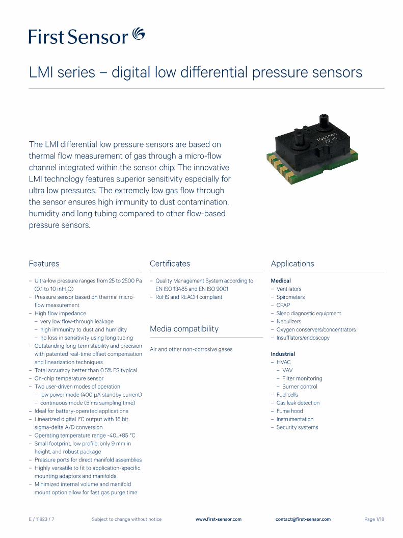
The LMI differential low pressure sensors are based on thermal flow measurement of gas through a micro-flow channel integrated within the sensor chip. The innovative LMI technology features superior sensitivity especially for ultra low pressures. The extremely low gas flow through the sensor ensures high immunity to dust contamination, humidity and long tubing compared to other flow-based pressure sensors.
E / 11823 / 7
LMI series – digital low differential pressure sensors
Page 2/18Subject to change without notice www.first-sensor.com [email protected]
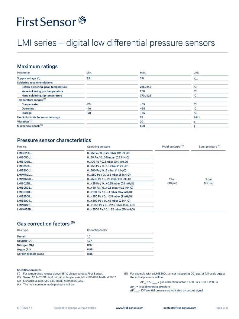
Part no. Operating pressure Proof pressure (4) Burst pressure (4)
LMIS025U... 0...25 Pa / 0...0.25 mbar (0.1 inH2O)
2 bar(30 psi)
5 bar(75 psi)
LMIS050U... 0...50 Pa / 0...0.5 mbar (0.2 inH2O)LMIS100U... 0...100 Pa / 0...1 mbar (0.4 inH2O)LMIS250U... 0...250 Pa / 0...2.5 mbar (1 inH2O)LMIS500U... 0...500 Pa / 0...5 mbar (1 inH2O)LMIM012U... 0...1250 Pa / 0...12.5 mbar (5 inH2O)LMIM025U... 0...2500 Pa / 0...25 mbar (10 inH2O)
LMIS025B... 0...±25 Pa / 0...±0.25 mbar (0.1 inH2O)LMIS050B... 0...±50 Pa / 0...±0.5 mbar (0.2 inH2O)LMIS100B... 0...±100 Pa / 0...±1 mbar (0.4 inH2O)LMIS250B... 0...±250 Pa / 0...±2.5 mbar (1 inH2O)LMIS500B... 0...±500 Pa / 0...±5 mbar (2 inH2O)LMIM012B... 0...±1250 Pa / 0...±12.5 mbar (5 inH2O)LMIM025B... 0...±2500 Pa / 0...±25 mbar (10 inH2O)
Specification notes(1) For temperature ranges above 85 °C please contact First Sensor.(2) Sweep 20 to 2000 Hz, 8 min, 4 cycles per axis, MIL-STD-883, Method 2007.(3) 5 shocks, 3 axes, MIL-STD-883E, Method 2002.4.(4) The max. common mode pressure is 5 bar.
(5) For example with a LMIS500... sensor measuring CO2 gas, at full-scale output
the actual pressure will be:
ΔPeff
= ΔPSensor
x gas correction factor = 500 Pa x 0.56 = 280 Pa
ΔPeff
= True differential pressure ΔP
Sensor= Differential pressure as indicated by output signal
Pressure sensor characteristics
Parameter Min. Max. Unit
Supply voltage VS 2.7 3.6 VDC
Soldering recommendations Reflow soldering, peak temperature 235...245 °CWave soldering, pot temperature 260 °CHand soldering, tip temperature 370...425 °C
Temperature ranges (1)
Compensated -20 +85 °COperating -40 +85 °CStorage -40 +85 °C
Humidity limits (non-condensing) 97 %RHVibration (2) 20 gMechanical shock (3) 500 g
Maximum ratings
Gas type Correction factor
Dry air 1.0Oxygen (O2) 1.07Nitrogen (N2) 0.97Argon (Ar) 0.98Carbon dioxide (CO2) 0.56
Gas correction factors (5)
E / 11823 / 7
LMI series – digital low differential pressure sensors
Page 3/18Subject to change without notice www.first-sensor.com [email protected]
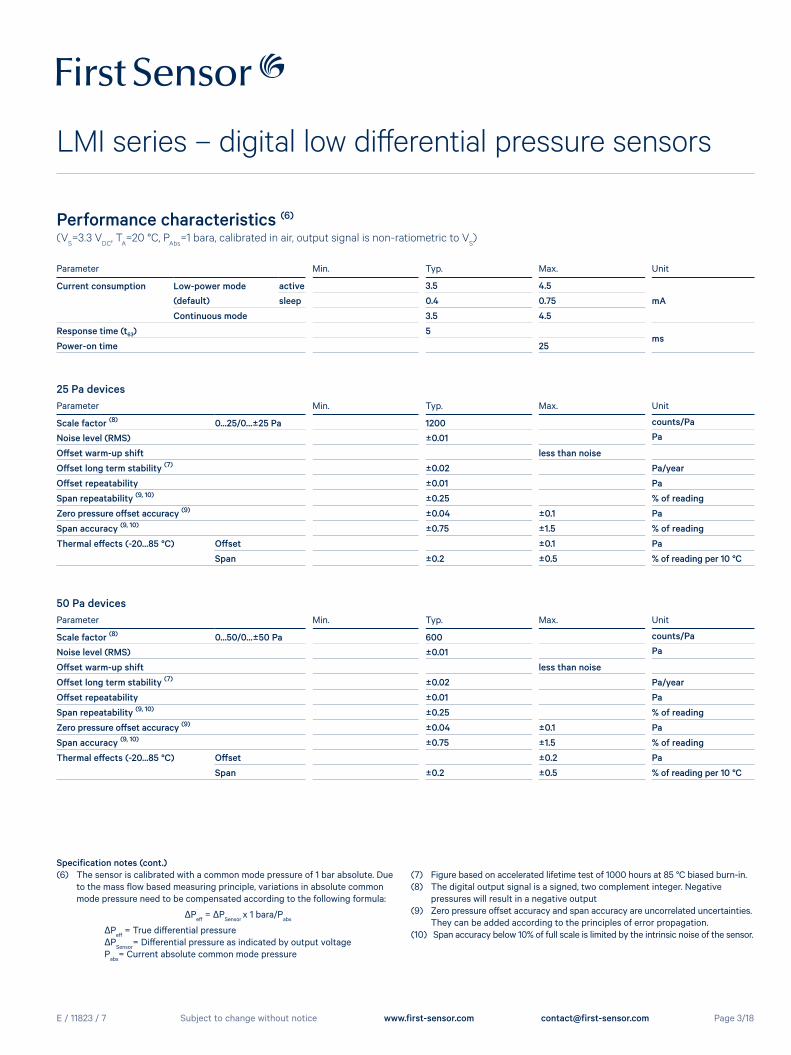
Performance characteristics (6)
(VS=3.3 V
DC, T
A=20 °C, P
Abs=1 bara, calibrated in air, output signal is non-ratiometric to V
S)
Parameter Min. Typ. Max. Unit
Current consumption Low-power mode active 3.5 4.5
mA(default) sleep 0.4 0.75
Continuous mode 3.5 4.5
Response time (t63) 5ms
Power-on time 25
Parameter Min. Typ. Max. Unit
Scale factor (8) 0...25/0...±25 Pa 1200 counts/Pa
Noise level (RMS) ±0.01 Pa
Offset warm-up shift less than noise
Offset long term stability (7) ±0.02 Pa/year
Offset repeatability ±0.01 Pa
Span repeatability (9, 10) ±0.25 % of reading
Zero pressure offset accuracy (9) ±0.04 ±0.1 Pa
Span accuracy (9, 10) ±0.75 ±1.5 % of reading
Thermal effects (-20...85 °C) Offset ±0.1 Pa
Span ±0.2 ±0.5 % of reading per 10 °C
25 Pa devices
Parameter Min. Typ. Max. Unit
Scale factor (8) 0...50/0...±50 Pa 600 counts/Pa
Noise level (RMS) ±0.01 Pa
Offset warm-up shift less than noise
Offset long term stability (7) ±0.02 Pa/year
Offset repeatability ±0.01 Pa
Span repeatability (9, 10) ±0.25 % of reading
Zero pressure offset accuracy (9) ±0.04 ±0.1 Pa
Span accuracy (9, 10) ±0.75 ±1.5 % of reading
Thermal effects (-20...85 °C) Offset ±0.2 Pa
Span ±0.2 ±0.5 % of reading per 10 °C
50 Pa devices
Specification notes (cont.)(6) The sensor is calibrated with a common mode pressure of 1 bar absolute. Due to the mass flow based measuring principle, variations in absolute common mode pressure need to be compensated according to the following formula:
ΔPeff
= ΔPSensor
x 1 bara/Pabs
ΔPeff
= True differential pressure ΔP
Sensor= Differential pressure as indicated by output voltage
Pabs
= Current absolute common mode pressure
(7) Figure based on accelerated lifetime test of 1000 hours at 85 °C biased burn-in.(8) The digital output signal is a signed, two complement integer. Negative pressures will result in a negative output (9) Zero pressure offset accuracy and span accuracy are uncorrelated uncertainties. They can be added according to the principles of error propagation.(10) Span accuracy below 10% of full scale is limited by the intrinsic noise of the sensor.
E / 11823 / 7
LMI series – digital low differential pressure sensors
Page 4/18Subject to change without notice www.first-sensor.com [email protected]
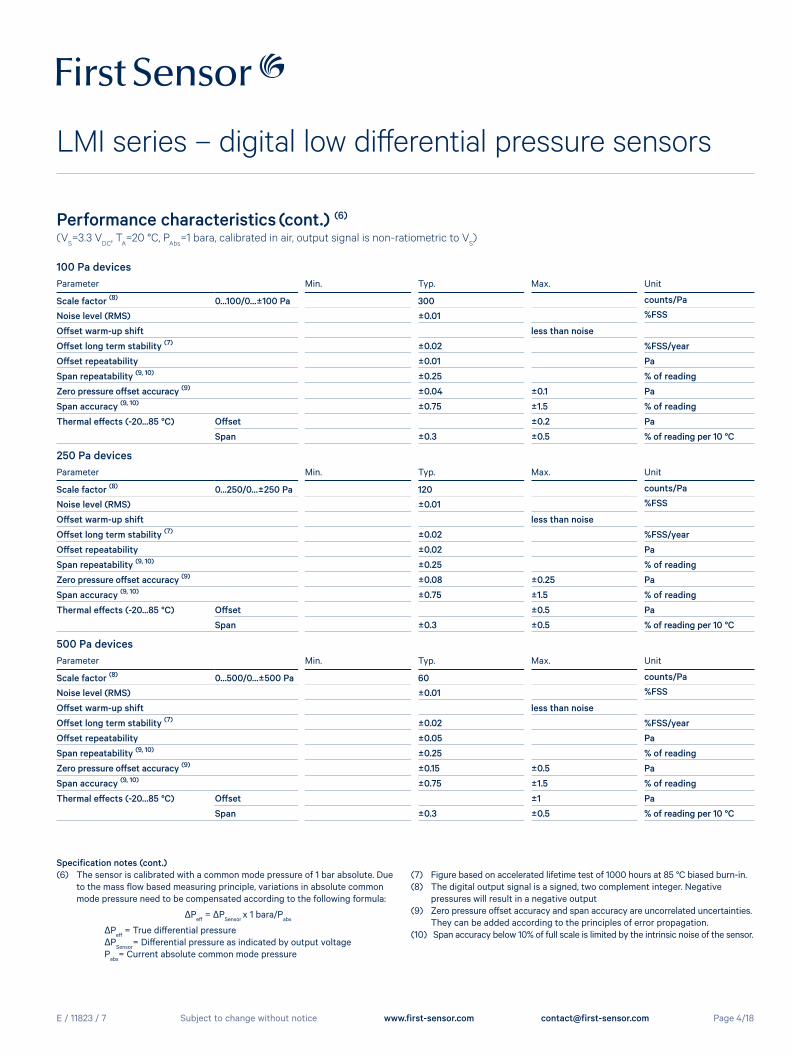
Performance characteristics (cont.) (6)
(VS=3.3 V
DC, T
A=20 °C, P
Abs=1 bara, calibrated in air, output signal is non-ratiometric to V
S)
Parameter Min. Typ. Max. Unit
Scale factor (8) 0...100/0...±100 Pa 300 counts/Pa
Noise level (RMS) ±0.01 %FSS
Offset warm-up shift less than noise
Offset long term stability (7) ±0.02 %FSS/year
Offset repeatability ±0.01 Pa
Span repeatability (9, 10) ±0.25 % of reading
Zero pressure offset accuracy (9) ±0.04 ±0.1 Pa
Span accuracy (9, 10) ±0.75 ±1.5 % of reading
Thermal effects (-20...85 °C) Offset ±0.2 Pa
Span ±0.3 ±0.5 % of reading per 10 °C
100 Pa devices
Parameter Min. Typ. Max. Unit
Scale factor (8) 0...250/0...±250 Pa 120 counts/Pa
Noise level (RMS) ±0.01 %FSS
Offset warm-up shift less than noise
Offset long term stability (7) ±0.02 %FSS/year
Offset repeatability ±0.02 Pa
Span repeatability (9, 10) ±0.25 % of reading
Zero pressure offset accuracy (9) ±0.08 ±0.25 Pa
Span accuracy (9, 10) ±0.75 ±1.5 % of reading
Thermal effects (-20...85 °C) Offset ±0.5 Pa
Span ±0.3 ±0.5 % of reading per 10 °C
250 Pa devices
Parameter Min. Typ. Max. Unit
Scale factor (8) 0...500/0...±500 Pa 60 counts/Pa
Noise level (RMS) ±0.01 %FSS
Offset warm-up shift less than noise
Offset long term stability (7) ±0.02 %FSS/year
Offset repeatability ±0.05 Pa
Span repeatability (9, 10) ±0.25 % of reading
Zero pressure offset accuracy (9) ±0.15 ±0.5 Pa
Span accuracy (9, 10) ±0.75 ±1.5 % of reading
Thermal effects (-20...85 °C) Offset ±1 Pa
Span ±0.3 ±0.5 % of reading per 10 °C
500 Pa devices
Specification notes (cont.)(6) The sensor is calibrated with a common mode pressure of 1 bar absolute. Due to the mass flow based measuring principle, variations in absolute common mode pressure need to be compensated according to the following formula:
ΔPeff
= ΔPSensor
x 1 bara/Pabs
ΔPeff
= True differential pressure ΔP
Sensor= Differential pressure as indicated by output voltage
Pabs
= Current absolute common mode pressure
(7) Figure based on accelerated lifetime test of 1000 hours at 85 °C biased burn-in.(8) The digital output signal is a signed, two complement integer. Negative pressures will result in a negative output (9) Zero pressure offset accuracy and span accuracy are uncorrelated uncertainties. They can be added according to the principles of error propagation.(10) Span accuracy below 10% of full scale is limited by the intrinsic noise of the sensor.
E / 11823 / 7
LMI series – digital low differential pressure sensors
Page 5/18Subject to change without notice www.first-sensor.com [email protected]
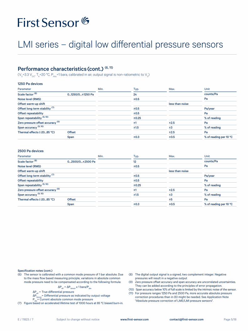
Performance characteristics (cont.) (6, 11)
(VS=3.3 V
DC, T
A=20 °C, P
Abs=1 bara, calibrated in air, output signal is non-ratiometric to V
S)
Parameter Min. Typ. Max. Unit
Scale factor (8) 0...1250/0...±1250 Pa 24 counts/Pa
Noise level (RMS) ±0.5 Pa
Offset warm-up shift less than noise
Offset long term stability (7) ±0.5 Pa/year
Offset repeatability ±0.5 Pa
Span repeatability (9, 10) ±0.25 % of reading
Zero pressure offset accuracy (9) ±1 ±2.5 Pa
Span accuracy (9, 10) ±1.5 ±3 % of reading
Thermal effects (-20...85 °C) Offset ±2.5 Pa
Span ±0.3 ±0.5 % of reading per 10 °C
1250 Pa devices
Specification notes (cont.)(6) The sensor is calibrated with a common mode pressure of 1 bar absolute. Due to the mass flow based measuring principle, variations in absolute common mode pressure need to be compensated according to the following formula:
ΔPeff
= ΔPSensor
x 1 bara/Pabs
ΔPeff
= True differential pressure ΔP
Sensor= Differential pressure as indicated by output voltage
Pabs
= Current absolute common mode pressure(7) Figure based on accelerated lifetime test of 1000 hours at 85 °C biased burn-in.
(8) The digital output signal is a signed, two complement integer. Negative pressures will result in a negative output (9) Zero pressure offset accuracy and span accuracy are uncorrelated uncertainties. They can be added according to the principles of error propagation.(10) Span accuracy below 10% of full scale is limited by the intrinsic noise of the sensor.(11) For pressure ranges 1250 Pa and 2500 Pa, more accurate absolute pressure correction procedures than in (6) might be needed. See Application Note "Absolute pressure correction of LME/LMI pressure sensors".
Parameter Min. Typ. Max. Unit
Scale factor (8) 0...2500/0...±2500 Pa 12 counts/Pa
Noise level (RMS) ±0.5 Pa
Offset warm-up shift less than noise
Offset long term stability (7) ±0.5 Pa/year
Offset repeatability ±0.5 Pa
Span repeatability (9, 10) ±0.25 % of reading
Zero pressure offset accuracy (9) ±1 ±2.5 Pa
Span accuracy (9, 10) ±1.5 ±3 % of reading
Thermal effects (-20...85 °C) Offset ±5 Pa
Span ±0.3 ±0.5 % of reading per 10 °C
2500 Pa devices
E / 11823 / 7
LMI series – digital low differential pressure sensors
Page 6/18Subject to change without notice www.first-sensor.com [email protected]
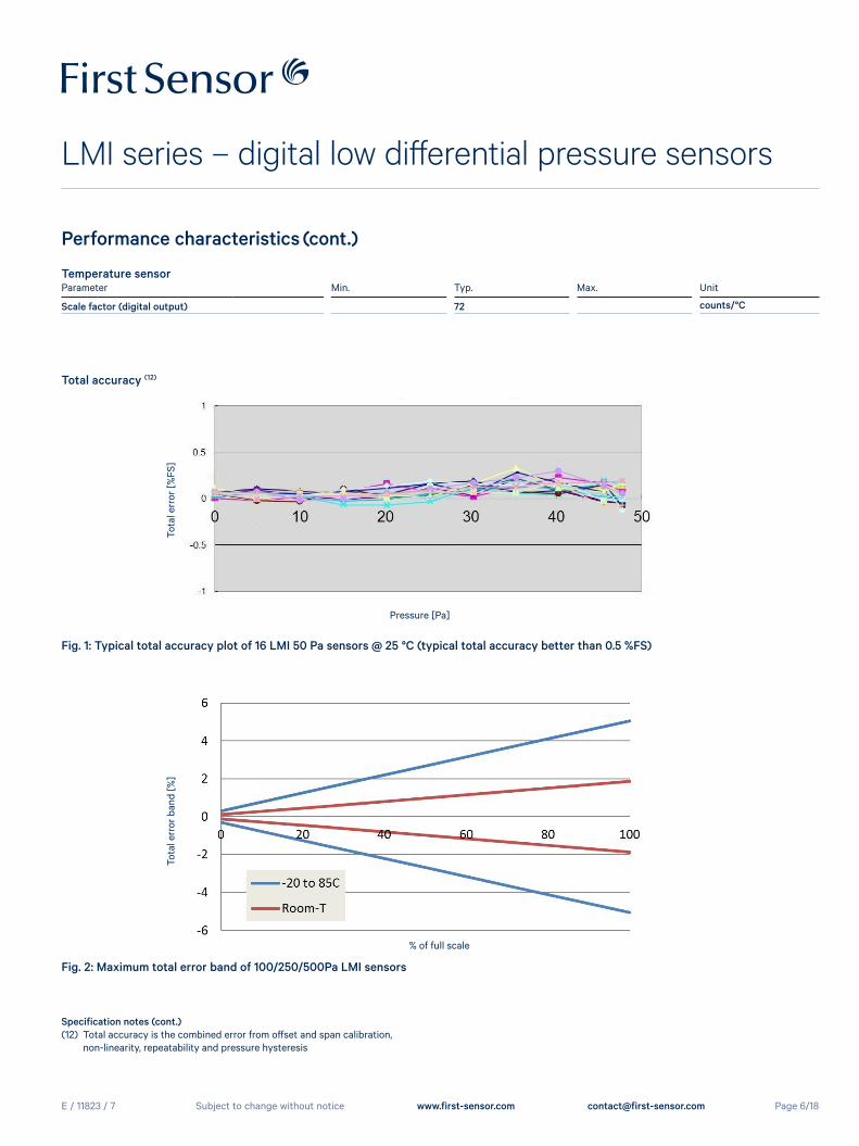
Performance characteristics (cont.)
Specification notes (cont.)(12) Total accuracy is the combined error from offset and span calibration, non-linearity, repeatability and pressure hysteresis
Fig. 1: Typical total accuracy plot of 16 LMI 50 Pa sensors @ 25 °C (typical total accuracy better than 0.5 %FS)
Fig. 2: Maximum total error band of 100/250/500Pa LMI sensors
Tota
l err
or b
and
[%]
% of full scale
Total accuracy (12)
Tota
l err
or [%
FS]
Pressure [Pa]
Temperature sensorParameter Min. Typ. Max. Unit
Scale factor (digital output) 72 counts/°C
E / 11823 / 7
LMI series – digital low differential pressure sensors
Page 7/18Subject to change without notice www.first-sensor.com [email protected]
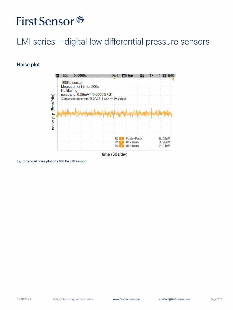
Noise plot
Fig. 3: Typical noise plot of a 100 Pa LMI sensor
E / 11823 / 7
LMI series – digital low differential pressure sensors
Page 8/18Subject to change without notice www.first-sensor.com [email protected]
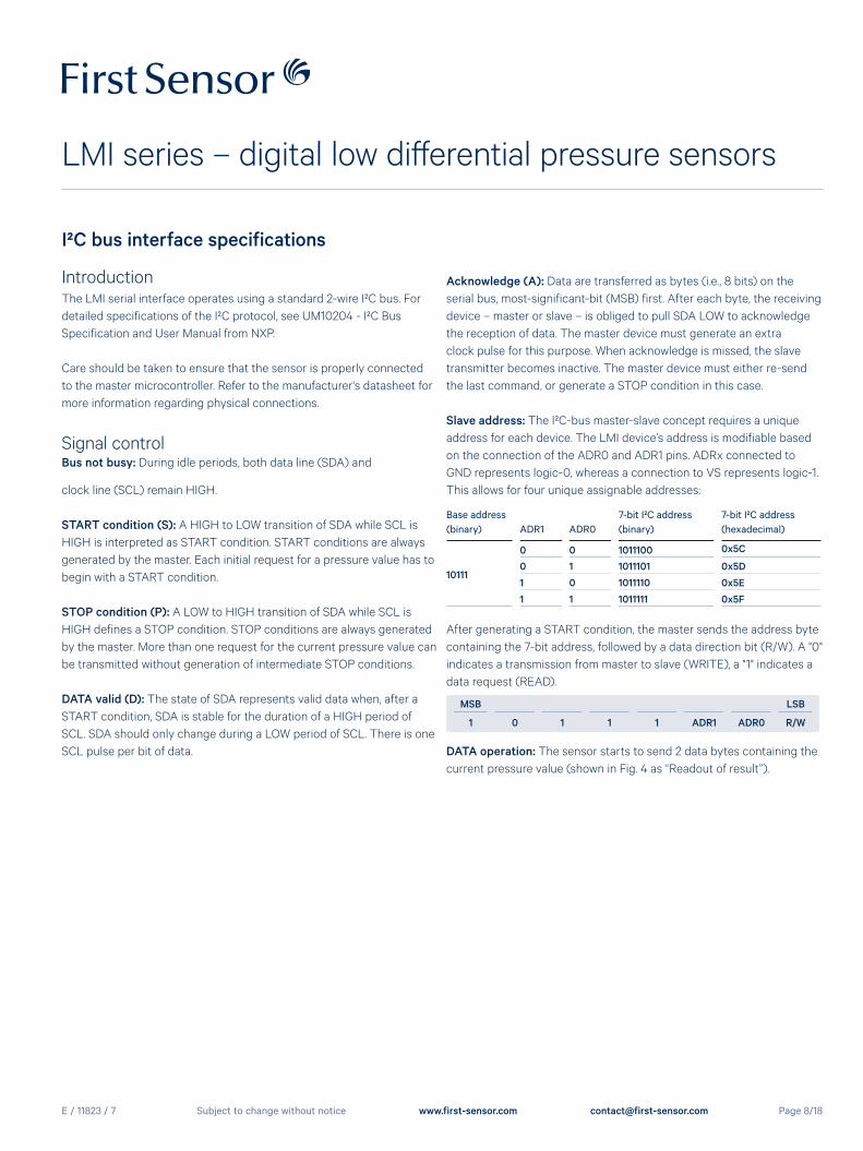
I²C bus interface specifications
IntroductionThe LMI serial interface operates using a standard 2-wire I²C bus. For detailed specifications of the I²C protocol, see UM10204 - I²C Bus Specification and User Manual from NXP.
Care should be taken to ensure that the sensor is properly connected to the master microcontroller. Refer to the manufacturer's datasheet for more information regarding physical connections.
Signal controlBus not busy: During idle periods, both data line (SDA) and
clock line (SCL) remain HIGH.
START condition (S): A HIGH to LOW transition of SDA while SCL is HIGH is interpreted as START condition. START conditions are always generated by the master. Each initial request for a pressure value has to begin with a START condition.
STOP condition (P): A LOW to HIGH transition of SDA while SCL is HIGH defines a STOP condition. STOP conditions are always generated by the master. More than one request for the current pressure value can be transmitted without generation of intermediate STOP conditions.
DATA valid (D): The state of SDA represents valid data when, after a START condition, SDA is stable for the duration of a HIGH period of SCL. SDA should only change during a LOW period of SCL. There is one SCL pulse per bit of data.
Acknowledge (A): Data are transferred as bytes (i.e., 8 bits) on the serial bus, most-significant-bit (MSB) first. After each byte, the receiving device – master or slave – is obliged to pull SDA LOW to acknowledge the reception of data. The master device must generate an extra clock pulse for this purpose. When acknowledge is missed, the slave transmitter becomes inactive. The master device must either re-send the last command, or generate a STOP condition in this case.
Slave address: The I²C-bus master-slave concept requires a unique address for each device. The LMI device’s address is modifiable based on the connection of the ADR0 and ADR1 pins. ADRx connected to GND represents logic-0, whereas a connection to VS represents logic-1. This allows for four unique assignable addresses:
Base address (binary) ADR1 ADR0
7-bit I²C address (binary)
7-bit I²C address (hexadecimal)
10111
0 0 1011100 0x5C
0 1 1011101 0x5D
1 0 1011110 0x5E
1 1 1011111 0x5F
After generating a START condition, the master sends the address byte containing the 7-bit address, followed by a data direction bit (R/W). A "0" indicates a transmission from master to slave (WRITE), a "1" indicates a data request (READ).
MSB LSB
1 0 1 1 1 ADR1 ADR0 R/W
DATA operation: The sensor starts to send 2 data bytes containing the current pressure value (shown in Fig. 4 as “Readout of result”).
E / 11823 / 7
LMI series – digital low differential pressure sensors
Page 9/18Subject to change without notice www.first-sensor.com [email protected]
/* ====================== PSEUDOCODE - RESET FIRMWARE ====================== */// Assumption: The sensor’s address is defined with ADR0 = ADR1 = 0.byte sensorAddress = 0x5c;byte resetCommand = 0x11;
// Write the command to the bus.i2c.sendStartCondition();i2c.beginTransmissionToAddress(sensorAddress); // Send 0xB8 (0x5C with R/W=0).i2c.writeCommandToBus(resetCommand); // Send 0x11.i2c.sendStopCondition();
I²C bus interface specifications (cont.)
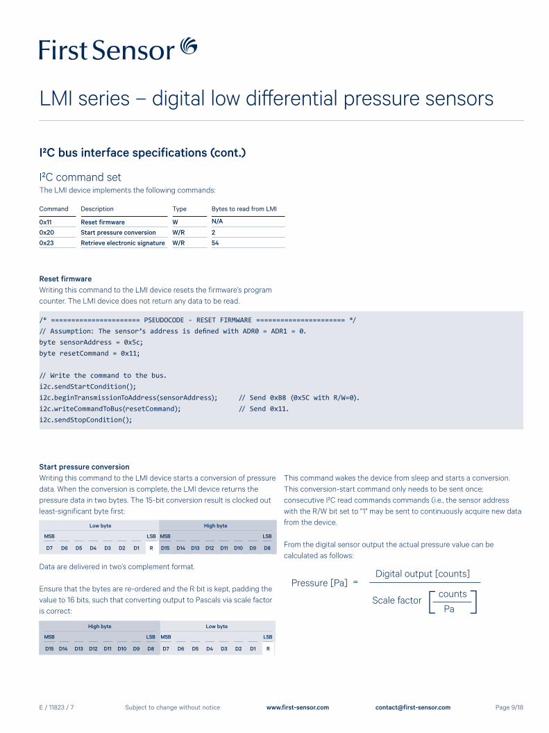
Start pressure conversionWriting this command to the LMI device starts a conversion of pressure data. When the conversion is complete, the LMI device returns the pressure data in two bytes. The 15-bit conversion result is clocked out least-significant byte first:
Low byte High byte
MSB LSB MSB LSB
D7 D6 D5 D4 D3 D2 D1 R D15 D14 D13 D12 D11 D10 D9 D8
Data are delivered in two’s complement format.
Ensure that the bytes are re-ordered and the R bit is kept, padding the value to 16 bits, such that converting output to Pascals via scale factor is correct:
High byte Low byte
MSB LSB MSB LSB
D15 D14 D13 D12 D11 D10 D9 D8 D7 D6 D5 D4 D3 D2 D1 R
This command wakes the device from sleep and starts a conversion. This conversion-start command only needs to be sent once; consecutive I²C read commands commands (i.e., the sensor address with the R/W bit set to "1" may be sent to continuously acquire new data from the device.
From the digital sensor output the actual pressure value can be calculated as follows:
I²C command setThe LMI device implements the following commands:
Command Description Type Bytes to read from LMI
0x11 Reset firmware W N/A
0x20 Start pressure conversion W/R 2
0x23 Retrieve electronic signature W/R 54
Reset firmwareWriting this command to the LMI device resets the firmware’s program counter. The LMI device does not return any data to be read.
Pressure [Pa] = Digital output [counts]
Scale factor
[
counts ]
Pa
E / 11823 / 7
LMI series – digital low differential pressure sensors
Page 10/18Subject to change without notice www.first-sensor.com [email protected]
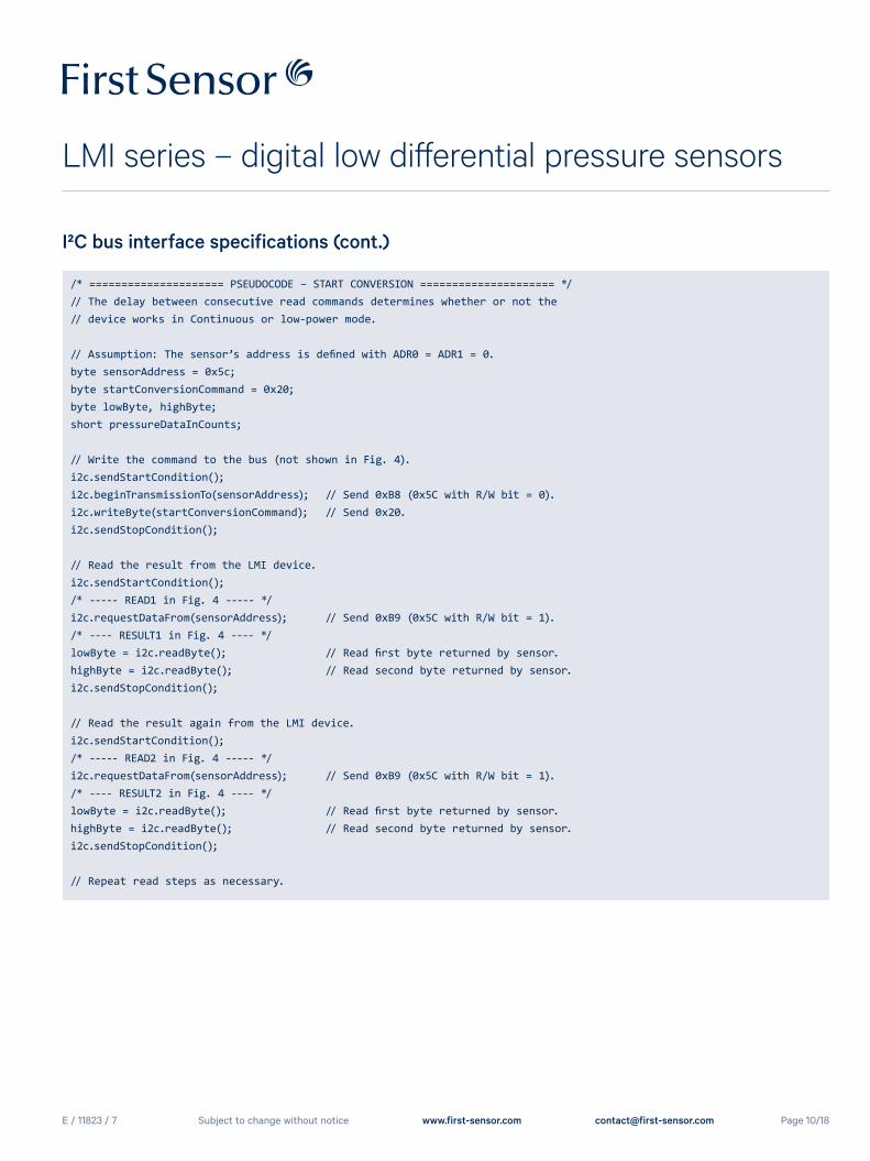
/* ===================== PSEUDOCODE – START CONVERSION ===================== */// The delay between consecutive read commands determines whether or not the // device works in Continuous or low-power mode.
// Assumption: The sensor’s address is defined with ADR0 = ADR1 = 0.byte sensorAddress = 0x5c; byte startConversionCommand = 0x20;byte lowByte, highByte;short pressureDataInCounts;
// Write the command to the bus (not shown in Fig. 4).i2c.sendStartCondition();i2c.beginTransmissionTo(sensorAddress); // Send 0xB8 (0x5C with R/W bit = 0).i2c.writeByte(startConversionCommand); // Send 0x20.i2c.sendStopCondition();
// Read the result from the LMI device.i2c.sendStartCondition();/* ----- READ1 in Fig. 4 ----- */i2c.requestDataFrom(sensorAddress); // Send 0xB9 (0x5C with R/W bit = 1)./* ---- RESULT1 in Fig. 4 ---- */lowByte = i2c.readByte(); // Read first byte returned by sensor.highByte = i2c.readByte(); // Read second byte returned by sensor.i2c.sendStopCondition(); // Read the result again from the LMI device.i2c.sendStartCondition();/* ----- READ2 in Fig. 4 ----- */i2c.requestDataFrom(sensorAddress); // Send 0xB9 (0x5C with R/W bit = 1)./* ---- RESULT2 in Fig. 4 ---- */lowByte = i2c.readByte(); // Read first byte returned by sensor.highByte = i2c.readByte(); // Read second byte returned by sensor.i2c.sendStopCondition();
// Repeat read steps as necessary.
I²C bus interface specifications (cont.)
E / 11823 / 7
LMI series – digital low differential pressure sensors
Page 11/18Subject to change without notice www.first-sensor.com [email protected]
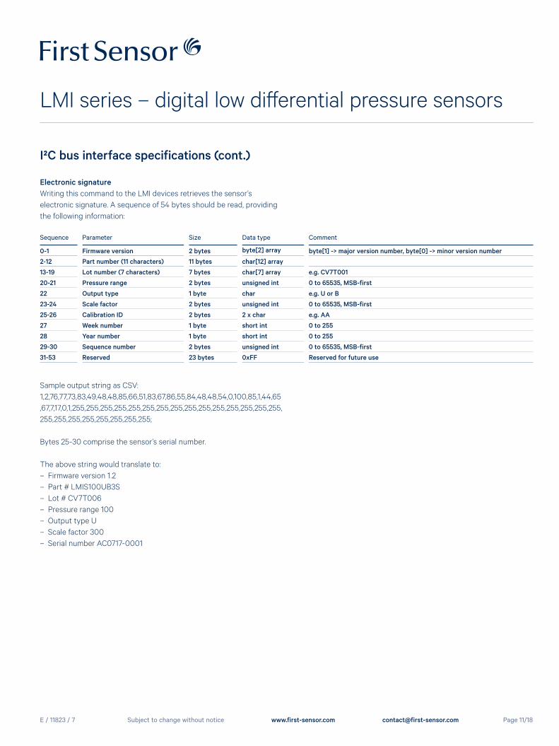
Electronic signatureWriting this command to the LMI devices retrieves the sensor’s electronic signature. A sequence of 54 bytes should be read, providing the following information:
Sequence Parameter Size Data type Comment
0-1 Firmware version 2 bytes byte[2] array byte[1] -> major version number, byte[0] -> minor version number
2-12 Part number (11 characters) 11 bytes char[12] array
13-19 Lot number (7 characters) 7 bytes char[7] array e.g. CV7T001
20-21 Pressure range 2 bytes unsigned int 0 to 65535, MSB-first
22 Output type 1 byte char e.g. U or B
23-24 Scale factor 2 bytes unsigned int 0 to 65535, MSB-first
25-26 Calibration ID 2 bytes 2 x char e.g. AA
27 Week number 1 byte short int 0 to 255
28 Year number 1 byte short int 0 to 255
29-30 Sequence number 2 bytes unsigned int 0 to 65535, MSB-first
31-53 Reserved 23 bytes 0xFF Reserved for future use
Sample output string as CSV:1,2,76,77,73,83,49,48,48,85,66,51,83,67,86,55,84,48,48,54,0,100,85,1,44,65,67,7,17,0,1,255,255,255,255,255,255,255,255,255,255,255,255,255,255,255,255,255,255,255,255,255,255,255;
Bytes 25-30 comprise the sensor’s serial number.
The above string would translate to: – Firmware version 1.2 – Part # LMIS100UB3S – Lot # CV7T006 – Pressure range 100 – Output type U – Scale factor 300 – Serial number AC0717-0001
I²C bus interface specifications (cont.)
E / 11823 / 7
LMI series – digital low differential pressure sensors
Page 12/18Subject to change without notice www.first-sensor.com [email protected]
I²C bus interface specifications (cont.)
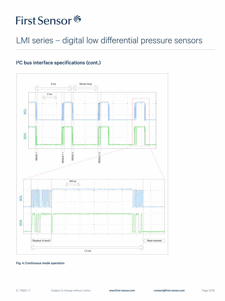
Fig. 4: Continuous mode operation
Readout of result Read received
SD
AS
CL
1.5 ms
SD
AS
CL
5 ms Sensor busy
200 μs
2 ms
RE
AD
1
RE
SU
LT 1
RE
AD
2
RE
SU
LT 2
E / 11823 / 7
LMI series – digital low differential pressure sensors
Page 13/18Subject to change without notice www.first-sensor.com [email protected]
I²C bus interface specifications (cont.)
6
4
2
0
Cur
rent
con
sum
ptio
n [m
A]
SCL
SDA
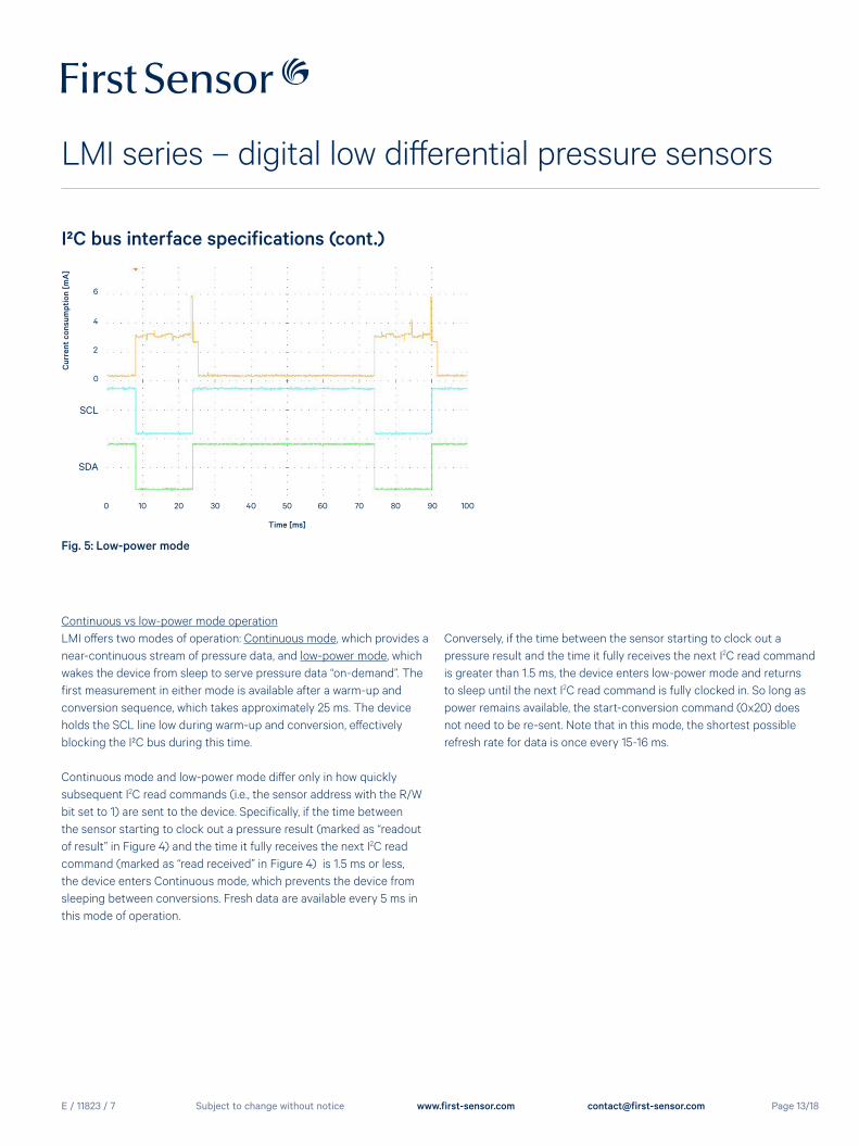
Fig. 5: Low-power mode
Time [ms]
0 10 20 30 40 50 60 70 80 90 100
Continuous vs low-power mode operationLMI offers two modes of operation: Continuous mode, which provides a near-continuous stream of pressure data, and low-power mode, which wakes the device from sleep to serve pressure data “on-demand”. The first measurement in either mode is available after a warm-up and conversion sequence, which takes approximately 25 ms. The device holds the SCL line low during warm-up and conversion, effectively blocking the I²C bus during this time.
Continuous mode and low-power mode differ only in how quickly subsequent I2C read commands (i.e., the sensor address with the R/W bit set to 1) are sent to the device. Specifically, if the time between the sensor starting to clock out a pressure result (marked as “readout of result” in Figure 4) and the time it fully receives the next I2C read command (marked as “read received” in Figure 4) is 1.5 ms or less, the device enters Continuous mode, which prevents the device from sleeping between conversions. Fresh data are available every 5 ms in this mode of operation.
Conversely, if the time between the sensor starting to clock out a pressure result and the time it fully receives the next I2C read command is greater than 1.5 ms, the device enters low-power mode and returns to sleep until the next I2C read command is fully clocked in. So long as power remains available, the start-conversion command (0x20) does not need to be re-sent. Note that in this mode, the shortest possible refresh rate for data is once every 15-16 ms.
E / 11823 / 7
LMI series – digital low differential pressure sensors
Page 14/18Subject to change without notice www.first-sensor.com [email protected]
I²C bus interface specifications (cont.)
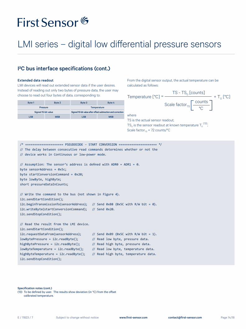
Extended data readoutLMI devices will read out extended sensor data if the user desires. Instead of reading out only two bytes of pressure data, the user may choose to read out four bytes of data, corresponding to:
Byte 1 Byte 2 Byte 3 Byte 4
Pressure Temperature
Signed 15-bit value Signed 16-bit value after offset subtraction and correction
LSB MSB LSB MSB
From the digital sensor output, the actual temperature can be calculated as follows:
Temperature [°C] = TS - TS0 [counts]
+ T0 [°C]
Scale factorTS[
counts ]
°C whereTS is the actual sensor readout;TS0 is the sensor readout at known temperature T0
(13);Scale factorTS = 72 counts/°C
Specification notes (cont.)(13) To be defined by user. The results show deviation (in °C) from the offset calibrated temperature.
/* ===================== PSEUDOCODE – START CONVERSION ===================== */// The delay between consecutive read commands determines whether or not the // device works in Continuous or low-power mode.
// Assumption: The sensor’s address is defined with ADR0 = ADR1 = 0.byte sensorAddress = 0x5c; byte startConversionCommand = 0x20;byte lowByte, highByte;short pressureDataInCounts;
// Write the command to the bus (not shown in Figure 4).i2c.sendStartCondition();i2c.beginTransmissionTo(sensorAddress); // Send 0xB8 (0x5C with R/W bit = 0).i2c.writeByte(startConversionCommand); // Send 0x20.i2c.sendStopCondition();
// Read the result from the LMI device.i2c.sendStartCondition();i2c.requestDataFrom(sensorAddress); // Send 0xB9 (0x5C with R/W bit = 1).lowBytePressure = i2c.readByte(); // Read low byte, pressure data.highBytePressure = i2c.readByte(); // Read high byte, pressure data.lowByteTemperature = i2c.readByte(); // Read low byte, temperature data.highByteTemperature = i2c.readByte(); // Read high byte, temperature data.i2c.sendStopCondition();
E / 11823 / 7
LMI series – digital low differential pressure sensors
Page 15/18Subject to change without notice www.first-sensor.com [email protected]
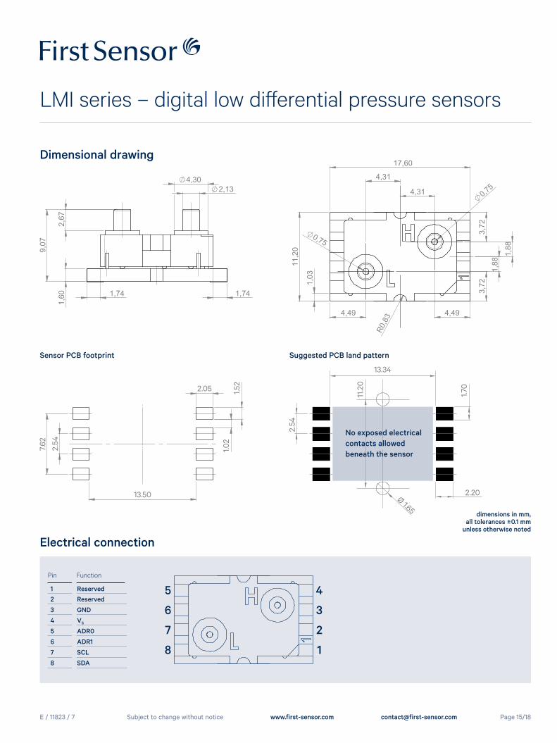
Dimensional drawing
Electrical connection
Pin Function
1 Reserved
2 Reserved
3 GND
4 VS
5 ADR0
6 ADR1
7 SCL
8 SDA
1
2
3
4
8
7
6
5
Sensor PCB footprint Suggested PCB land pattern
13.34
2.20
2.54
11.2
0
1.70
Ø 1.65
7.62
2.54
1.52
1.02
13.50
2.05
No exposed electrical contacts allowed beneath the sensor
dimensions in mm, all tolerances ±0.1 mm
unless otherwise noted
E / 11823 / 7
LMI series – digital low differential pressure sensors
Page 16/18Subject to change without notice www.first-sensor.com [email protected]
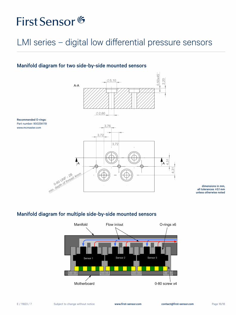
Manifold diagram for two side-by-side mounted sensors
Manifold diagram for multiple side-by-side mounted sensors
Recommended O-rings: Part number: 90025K119www.mcmaster.com
dimensions in mm, all tolerances ±0.1 mm
unless otherwise noted
E / 11823 / 7
LMI series – digital low differential pressure sensors
Page 17/18Subject to change without notice www.first-sensor.com [email protected]
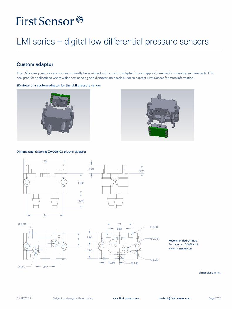
Custom adaptor
The LMI series pressure sensors can optionally be equipped with a custom adaptor for your application-specific mounting requirements. It is designed for applications where wider port spacing and diameter are needed. Please contact First Sensor for more information.
3D views of a custom adaptor for the LMI pressure sensor
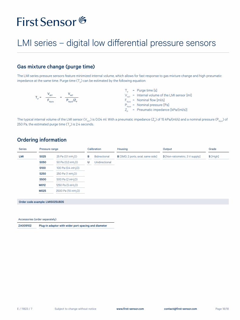
29
Ø 2.90
24
13.60
9.65
5.90
Ø 1.90 12.44
3.20
17
8.62
10.50
11.20
5.309
Ø 2.82Ø 5.25
Ø 2.75
Ø 1.30
Dimensional drawing ZA009102 plug-in adaptor
dimensions in mm
Recommended O-rings: Part number: 90025K119www.mcmaster.com
E / 11823 / 7
LMI series – digital low differential pressure sensors
Page 18/18Subject to change without notice www.first-sensor.com [email protected]
Gas mixture change (purge time)
The LMI series pressure sensors feature minimized internal volume, which allows for fast response to gas mixture change and high pneumatic impedance at the same time. Purge time (T
P) can be estimated by the following equation:
TP = Purge time [s]
VINT
= Internal volume of the LMI sensor [ml] F
Nom = Nominal flow [ml/s]
PNom
= Nominal pressure [Pa] Z
P = Pneumatic impedance [kPa/(ml/s)]
The typical internal volume of the LMI sensor (VINT
) is 0.04 ml. With a pneumatic impedance (ZP) of 15 kPa/(ml/s) and a nominal pressure (P
Nom) of
250 Pa, the estimated purge time (TP) is 2.4 seconds.
TP
= V
INT
= VINT
FNorm
PNorm
/ZP
Accessories (order separately)
ZA009102 Plug-in adaptor with wider port spacing and diameter
Ordering informationSeries Pressure range Calibration Housing Output Grade
LMI S025 25 Pa (0.1 inH2O) B Bidirectional B [SMD, 2 ports, axial, same side] 3 [Non-ratiometric, 3 V supply] S [High]
S050 50 Pa (0.2 inH2O) U Unidirectional
S100 100 Pa (0.4 inH2O)
S250 250 Pa (1 inH2O)
S500 500 Pa (2 inH2O)
M012 1250 Pa (5 inH2O)
M025 2500 Pa (10 inH2O)
Order code example: LMIS025UB3S


![~V4 ffi~~~~~@ti~T~ ~~~~~(g~ ©©lMi]lMi]~[M[Q) …](https://img.pdfslide.us/doc/110x75/61cc5ca722583c59e2144e35/v4-ffitit-g-lmilmimq-.jpg)