Embed Size (px)
DESCRIPTION
Â
Citation preview

Instructions – Garage Door Operator Model LiftMaster LM60XX, LM80XXGB
Chamberlain GmbH
D66793 Saarwellingen
www.chamberlain.de

1-e
n
The Protector System must be installed when theforce at the edge of the closing door force exceeds400N (40kg). Excessive force will interfere with theproper operation of the Safety Reverse System ordamage the garage door.
Permanently fasten the caution label adjacent to the wall-mounted door control control button as a reminderof safe operating procedures.
Disengage all existing garage door locks to avoiddamage to garage door.
Install the lighted door control button (or any additionalpush buttons) in a location where the garage door isvisible, at a height of at least 1.5m and out of thereach of children. Do not allow children to operatepush button(s) or remote control(s). Serious personalinjury from a closing garage door may result frommisuse of the opener.
Activate opener only when the door is in full view,free of obstructions and opener is properly adjusted.No one should enter or leave the garage while thedoor is in motion. Do not allow children to play nearthe door.Use manual release only to disengage the trolley and, ifpossible, only when the door is closed. Do not use thered handle to pull the door open or closed.
Disconnect electric power to the garage door openerbefore making repairs or removing covers.This product is provided with a power supply cord ofspecial design which, if damaged, must be replacedby a power supply cord of the same type; such apower supply cord may be obtained and fitted by aspecialist.Children should be supervised to ensure that they do notplay with the appliance.
Failure to comply with the following instructions may result in serious personal injury or property damage.
• Read these instructions carefully
• The garage door opener is designed and tested to offer reasonable safe service provided it is installed and operated
in strict accordance with the instructions in this manual.
These safety alert symbols mean Warning – a personal safety or property damage instruction. Read these instructions
carefully.
Warning: If your garage has no service entrance door, Model 1702E Outside Quick Release must be installed. This accessory allowsmanual operation of the garage door from outside in case of power failure.
Keep garage door balanced. Do not let the garagedoor opener compensate for a binding or stickinggarage door. Sticking or binding doors must be repaired.Garage doors, door springs, cables, pulleys, bracketsand their hardware are under extreme tension and cancause serious personal injury. Do not attempt toloose, move or adjust them. Call for garage doorservice.
Do not wear rings, watches or loose clothing whileinstalling or servicing a garage door opener.
To avoid serious personal injury from entanglement,remove all ropes connected to the garage doorbefore installing the door opener.
Installation and wiring must be in compliance with yourlocal building and electrical codes. This is a class 2double insulated product, connection to earth is notrequired or provided.Lightweight doors of fiberglass, aluminum or steelmust be substantially reinforced to avoid doordamage. (See page 3.) The best solution is to checkwith your garage door manufacturer for an openerinstallation reinforcement kit.
The safety reverse system test is very important.Your garage door MUST reverse on contact with a
50mm obstacle placed on the floor. Failure to properly
adjust the opener may result in serious personal injury
from a closing garage door. Repeat the test once amonth and make any needed adjustments.
This unit should not be installed in a damp or wetspace.Door must not extend over public byway duringoperation.This appliance is not intended for use by persons(including children) with reduced physical sensory ormental capabilities, or lack of experience andknowledge, unless they have been given supervision orinstruction concerning use of the appliance by a personresponsible for their safety.
Start by Reading These Important Safety Instructions
Contents Page IllustrationSafety Rules . . . . . . . . . . . . . . . . . . . . . . . 1
Before you Begin . . . . . . . . . . . . . . . . . . . 2
Door Types . . . . . . . . . . . . . . . . . . . . . . . . 2 . . . . . . . . . . . . . . . . 1
Tools Required . . . . . . . . . . . . . . . . . . . . . 2 . . . . . . . . . . . . . . . . 2
Hardware Provided . . . . . . . . . . . . . . . . . 2 . . . . . . . . . . . . . . . . 3
Completed Installation . . . . . . . . . . . . . . 2 . . . . . . . . . . . . . . . . 4
Assembly . . . . . . . . . . . . . . . . . . . . . . . . . .2 . . . . . . . . . . . . . 5-11
Installation . . . . . . . . . . . . . . . . . . . . . . . 2-4 . . . . . . . . . . . . 12-21
Programming your Opener & Remote . . 4 . . . . . . . . . . . . . . . 22
Programming your Keyless Entry . . . . . .5 . . . . . . . . . . . . . . .23
Using the Wall-Mounted Door Control . .5 . . . . . . . . . . . . . . .24
Adjustment . . . . . . . . . . . . . . . . . . . . . . . . 5 . . . . . . . . . . . . 25-26
Test the Safety Reversal System . . . . . .5 . . . . . . . . . . . . .27
Install the Protector System™
(Optional) . . . . . . . . . . . . . . . . . . . . . . . . . 6 . . . . . . . . . . . . 28
Special Features of the LM60, LM80 . . . .6 . . . . . . . . . . . . 29
Accessories . . . . . . . . . . . . . . . . . . . . . . . 6 . . . . . . . . . . . . 30
Replacement Parts . . . . . . . . . . . . . . . . . . 6 . . . . . . . . . 31-32
Having a Problem? . . . . . . . . . . . . . . . 6-7
Care of your Opener . . . . . . . . . . . . . . . . 7
Maintenance of your Operator . . . . . . . . 7
Operation of your Opener . . . . . . . . . . . . 8
Specifications . . . . . . . . . . . . . . . . . . . . . . 8
WARNING

2-e
n
ASSEMBLY SECTIONIMPORTANT: If you have a canopy door, you need to use theinstructions packed with The Chamberlain Arm™ Accessory inconjunction with this Owner's Manual when assembling the rail.
Completed InstallationAs you proceed with the assembly, installation and adjustment
procedures in this manual, you may find it helpful to refer back to
this illustration of a completed installation.
(1) Header Sleeve
(2) Idler Pulley Bracket
(3) Trolley
(4) Rail
(5) Chain/Belt
(6) Hanging Bracket
(7) Power Cord
(8) Opener
(9) Light Lens
(10) Manual Release
Rope & Handle
(11) Curved Door Arm
(12) Straight Door Arm
(13) Door Bracket & Plate
(14) Header Bracket
(15) Trolley Release Arm
(1) Hex Bolt
(2) Clevis Pin
(3) 8mm Carriage Bolt
(4) Wood Screws
(5) Sheet Metal Screws
(6) Clevis Pin
(7) Rope
(8) Handle
(9) Insulated Staples
(10) Anchor
(11) Concrete Anchor
(12) Lock Washer
(13) Hex Nut
(14) Ring Fastener
(15) Metric Tapping Screw
(16) Hex Screw
(17) Stop Bolt
(18) Spring
(19) Flat Washer
(20) Lock Nut
(21) Rail GreaseFlat
Hardware Provided3
4
Assemble the RailGrease inside edges of rail sections using grease (1). Place rail pieces
(2) on flat surface for assembly. All four rail sections are
interchangeable. Slide rail brace (3) onto rail section. Connect rail by
sliding rail brace onto next rail section. Tap rail assembly (4) on piece
of wood (5) until rail sections are flush. Repeat with remaining rail
sections.
5
Install the Chain/BeltRemove chain/belt from carton and lay chain out on floor (do not allow
chain/belt to twist).
A. Chain: Push pins of master link bar (3) through chain link (4) and
hole in trolley (5). (see picture) Push cap (2) over pins and onto
notches. Slide clip-on spring (1) over cap and onto pin notches until
both pins are securely locked in place.
B. Belt: Hook the trolley connector (6) into the slot (7) on the
trolley (8).
6
Insert Trolley & Idler Pulley Bracket intoRail
Slide idler pulley bracket (1) and inner trolley (2) into back (opener)
end of rail assembly (3), be sure to insert idler pulley bracket as
shown. Arrow on trolley (7) must face toward front (header) end of rail
(4). Push idler pulley bracket toward front (header) end of rail (4).
Insert carriage bolt (5) into bolt cut out in the idler pulley bracket (6).
7
Attach Trolley to RailSlide outer trolley (1) into back (opener) end of the rail assembly (2),
be sure end with trolley release arm (3) is heading in direction of
opener. Slide outer trolley down rail until it engages with inner trolley.
8
Fasten Rail to Opener and InstallChain/Belt
Remove four washered bolts (1) from top of opener. Place rail (2) on
opener, flush with stop (3) on top of opener. Wrap chain/belt (4) over
sprocket (5). Push idler pulley bracket assembly toward front of the rail
to eliminate excess slack in chain/belt. Align bolt holes on brackets (6)
with bolt holes on opener. Secure brackets to opener with previously
removed bolts. Tighten bolts securely. The opener sprocket teethmust engage the chain/belt.CAUTION: Use only those bolts mounted in the top of opener.
Use of any other bolts will cause serious damage to opener.
9
Attach Sprocket CoverPlace sprocket cover (1) on top of the opener (2), secure with screws
(3). Insert bolt (4) into trolley stop hole (5), secure with washer (6) and
nut (7).
10
Assemble Header Sleeve and TightenChain/Belt
Slide header sleeve (1) onto rail (5). Slide flat washer (3), spring (2)
and washer (3) onto carriage bolt (4). Thread nut (6) onto carriage bolt
until finger tight. Use an open end wrench (7) to tighten nut until the
chain/belt is approximately 2mm above the base of the rail at its
midpoint. DO NOT OVER TIGHTEN THE CHAIN OR BELT. See
image (8).
11
INSTALLATION SECTIONWear protective goggles when working overhead to protect youreyes from injury.Disengage all existing garage door locks to avoid damage to thegarage door.To avoid serious personal injury from entanglement, remove allropes connected to the garage door before installing the opener.It is recommended that the opener be installed 2,1m (7 feet) or more
above the floor where space permits.
Tools Required2
Door TypesA. One-Piece Door with Horizontal Track Only.
B. One-Piece Door with Horizontal and Vertical Track – Special doorarm (E, The Chamberlain Arm™) and The Protector System™required. See your dealer.
C. Sectional Door with Curved Track – See 20B – connect door arm.The Protector System™ is required for doors that are over 2.5m inheight.
D. Canopy door – Special door arm (E, The Chamberlain Arm™)and The Protector System™ required. See your dealer.
E. The Chamberlain Arm™ for use on door types B and D.
1
Before You Begin1. Look at the wall or ceiling above the garage door. The header
bracket must be securely fastened to structural supports.
2. Do you have a finished ceiling in your garage? If so, a supportbracket and additional fastening hardware (not supplied) may berequired.
3. Depending on your door's construction, you might need a specialdoor arm. See your dealer.
4. Do you have an access door in addition to the garage door? Ifnot, Model 1702E Outside Quick Release Accessory is required.

3-e
n
Fasten Door Bracket
If you have a canopy garage door, a door arm conversion kit is required.Follow the installation instructions included with the replacement doorarm. Exercise care in removing and assembling arm conversion kit. Keepfingers away from the sliding parts.NOTE: Horizontal and vertical reinforcement is needed for lightweightgarage doors.Sectional and One-Piece Door Installation Procedure:
Door bracket (1) has left and right side fastening holes. If your
installation requires top and bottom fastening holes use both the door
bracket and door bracket plate (2) as shown.
1. Center door bracket (with or without door bracket plate, as required)
at the top inside face of door as shown. Mark holes.
A.Standard Sectional or One-piece doors: locate bracket at
inside face of the door.
B. Sectional doors with two horizontal roller channels: 150 -
250mm below the top of the door.
2. A. Wooden doors
Drill 8mm holes (5/16") and fasten the door bracket with nut,
lock washer, and carriage bolt (3).
B. Sheet metal doors
Fasten with wood screws (4).
C. One-piece door optional
Fasten with wood screws (4).
19
Assemble Door Arm A. ONE-PIECE DOOR INSTALLATION:
Fasten the straight (1) and curved (2) door arm sections together to
the longest possible length (with a 2 or 3 hole overlap) using hardware
(3,4 and 5). With the door closed connect the straight door arm section
(1) to the door bracket with clevis pin (6). Secure with ring fastener (7).
Disconnect the inner and outer trolley. Slide the outer trolley back
toward the opener and join the curved arm (2) to the connector hole in
the trolley (8) with clevis pin (6). It may be necessary to lift the door
slightly to make the connection. Secure with ring fastener (7).
NOTE: When setting the up limit, the door should not have a“backward” slant when fully open. A slight backward slant (9) willcause unnecessary bucking and/or jerking operation as the door isbing opened or closed from the fully open position.B. SECTIONAL DOOR INSTALLATION:
Connect according to Figure B, then proceed to Step 21.
20
Attach Rail to Header BracketPosition opener on garage floor below the header bracket. Use
packing material to protect the cover. Raise rail until holes in the
header sleeve and holes in the header bracket align. Join with clevis
pin (1). Insert ring fastener (2) to secure.
NOTE: To enable the rail to clear sectional door springs, it may benecessary to lift opener onto a temporary support. The opener musteither be secured to a support or held firmly in place by anotherperson.
14
Position the OpenerNOTE: A 25mm (1") board (1) is convenient for setting an ideal door-to-rail distance (unless headroom is not sufficient).Raise the opener onto a stepladder. Open garage door. Place a 25mm
(1") board (1) laid flat on the top section of door near the centerline as
shown. Rest the rail on the board.
If the raised door hits the trolley, pull down on the trolley release arm
to disconnect the inner and outer trolley sections. The trolley can
remain disconnected until connecting door arm to trolley is completed.
15
Hang the OpenerThe opener must be securely fastened to a structural support of
the garage.
Three representative installations are shown. Yours may be different.
Hanging brackets (1) should be angled (Figure A) to provide rigid
support. On finished ceilings, (Figure B) attach a sturdy metal bracket
(not supplied) (4) to a structural support before installing the opener.
For concrete ceiling mount, (Figure C), use concrete anchors (5)
provided.
On each side of opener measure the distance from the opener to the
structural support (or ceiling).
Cut both pieces of the hanging bracket to required lengths. Flatten one
end of each bracket and bend or twist to fit the fastening angles. Do
not bend at the bracket holes. Drill 4,5mm (3/16") pilot holes in the
structural supports (or ceiling). Attach brackets to supports with wood
screws (2).
Lift opener and fasten to hanging brackets with screw, lock washer
and nut (3). Check to make sure rail is centered over the door.
REMOVE 25mm (1") board. Operate door manually. If door hits the
rail, raise header bracket. Use rail grease and lubricate bottom surface
of rail (6).
16
Attach Emergency Release Rope & HandleThread one end of rope (1) through hole in top of red handle so
"NOTICE" reads right side up as shown (3). Secure with an overhand
knot (2). Knot should be at least 25mm (1") from end of the rope to
prevent slipping.
Thread other end of rope through hole in release arm of the outer
trolley (4). Adjust rope length so that handle is 1,8m (6 feet) above the
floor. Secure with an overhand knot.
NOTE: If it is necessary to cut rope, heat seal cut end with a match orlighter to prevent fraying.
17
Connect Electric PowerTO AVOID INSTALLATION DIFFICULTIES, DO NOT RUN THEGARAGE DOOR OPENER UNTIL INSTRUCTED TO DO SO.Connect the door opener only to an outlet controlled by a doublepole switch.
Install LightGently pull lens (2) downward until the lens hinge is in the fully open
position. Do not remove the lens. Install a 24V/21W maximum light
bulb (1) in the socket as shown. The light will turn on and remain lit for
2-1/2 minutes when power is connected. After 2-1/2 minutes it will turn
off. Reverse the procedure to close the lens.
18
Position the Header Bracket
The header bracket must be rigidly fastened to a structuralsupport of the garage. Reinforce the wall or ceiling with a 50 mm(1-1/2") board if necessary. Failure to comply may result inimproper operation of safety reverse system.You can attach the header bracket either to the header wall (1) or to
the ceiling (3). Follow the instructions which will work best for your
particular requirements.
With the door closed, mark the vertical centerline (2) of the garage
door. Extend line onto header wall above the door.
Open door to highest point of travel. Draw an intersecting horizontal
line (4) on header wall 5 cm (2") above high point to provide travel
clearance for top edge of door.
12
Install the Header BracketNOTE: Refer to vertical center and horizontal lines created in step12 for proper placement of header bracket.A. Wall Mount: Center the header bracket (1) on the vertical center
line (2) with the bottom edge of the header bracket on the
horizontal line (4) (with the arrow pointing toward the ceiling). Mark
all of the header bracket holes (5). Drill 4,5 mm (3/16") pilot holes
and fasten the header bracket with wood screws (3).
B. Ceiling Mount: Extend vertical center line (2) onto the ceiling.
Center the header bracket (1) on the vertical mark no more than
150 mm (6") from the wall. Make sure the arrow is pointing toward
the opener. Mark all of the header bracket holes (5). Drill 4,5 mm
(3/16") pilot holes and fasten the header bracket with wood screws
(3). For concrete ceiling mount, use concrete anchors (6) provided.
13

4-e
n
Install Door ControlLocate door control where the garage door is visible, away fromdoor and door hardware and out of the reach of children. Mountat least 1,5 m (5 feet) above the floorSerious personal injury from a moving garage door may resultfrom misuse of opener. Do not allow children to operate the doorcontrol or remote control transmitter.Permanently fasten the caution label permanently to the wall nearthe door control as a reminder of safe operating procedures.There are 2 terminals (1) on the back of the door control (2). Strip
about 6mm (1/4") of insulation from bell wire (4). Separate wires
enough to connect the white/red wire to RED terminal screw 1 and the
white wire to WHT terminal screw 2.
Fasten the door control to an inside garage wall with sheet metal
screws (3) provided. Drill 4mm (5/32") holes and use anchors (6) if
installing into drywall. A convenient place is beside the service door
and out of reach of children.
Run the bell wire up the wall and across the ceiling to the garage door
opener. Use insulated staples (5) to secure wire. The receiver quick
connect terminals are located behind the light lens of the opener.
Connect the bell wire to the terminals as follows: white/red to red (1)
and white to white (2).
Operation of the Door Control
Press to open or close the door. Press again to stop the door while
moving.
21
Multi-function Door Control (78LM Optional Accessory): Press the
white square to open or close the door. Press again to stop the door
while it is moving.
Light Feature: Press the Light button to turn the opener light on or off.
If you turn it on and then activate the opener, the light will remain on
for 2-1/2 minutes. Press again to turn it off sooner. The Light button
will not control the opener lights when the door is in motion.
Lock Feature: Prevents operation of the door from portable remote
controls. However, the door will open and close from the Door Control
push button, the Outside Keylock and the Keyless Entry Accessories.
• To activate: Press and hold the Lock button for 2 seconds. The push
button light will flash as long as the Lock feature is on.
• To turn off: Press and hold the Lock button again for 2 seconds. The
push button light will stop flashing. The Lock feature will also turn off
whenever the “LEARN” button on the control panel is activated.
Program your Opener & Remote/WirelessWall Control
Activate the opener only when door is in full view, free ofobstruction and properly adjusted. No one should enter or leavegarage while door is in motion. Do not allow children to operatepush button(s) or remote(s). Do not allow children to play nearthe door.Your garage door opener receiver and remote control transmitter are
set to a matching code. If you purchase additional remote controls, the
garage door opener must be programmed to accept the new remote
code.
Program the Receiver to Match Additional Remote Control Codes:
Using the orange “LEARN” Button
1. Press and release the orange “learn” button on the opener. The
learn indicator light will glow steadily for 30 seconds (1).
2. Within 30 seconds, press and hold the button on the hand-held
remote that you wish to operate your garage door (2).
3. Release the button when the opener light blinks. It has learned the
code. If the light bulb is not installed, two clicks will be heard (3).
Using the Multi-Function Door Control:
1. Press and hold the button on the hand-held remote that you wish to
operate your garage door (4).
2. While holding the remote button, press and hold the LIGHT button
on the Multi-Function Door Control (5).
3. Continue holding both buttons while you press the push bar on the
Multi-Function Door Control (all three buttons are held) (6).
4. Release buttons when the opener light blinks. It has learned the
code. If the light bulb is not installed, two clicks will be heard (7).
Now the opener will operate when the remote control push button is
pressed. If you release the remote control push button before the
opener light flashes, the opener has not learned the code.
To Erase all Remote Control Codes
To deactivate any unwanted remote, first erase all codes: Press and
hold the orange “learn” button on opener until the learn indicator light
goes out (approximately 6 seconds). All previous codes are now
erased. Reprogram each remote or keyless entry you wish to use.
3-Channel Remote:
If provided with your garage door opener, the large button is factory
programmed to operate it. Additional buttons on any rolling code
3-channel remote or mini-remote can be programmed to operate this
or other rolling code garage door openers.
22

5-e
n
Program your Keyless EntryActivate the opener only when door is in full view, free ofobstruction and properly adjusted. No one should enter or leavegarage while door is in motion. Do not allow children to operatepush button(s) or remote(s). Do not allow children to play nearthe door.NOTE: Your new Keyless Entry must be programmed to operate yourgarage door opener.Program the Receiver to Match Additional Remote Control Code
Using the orange “LEARN” Button:
1. Press and release the orange “learn” button (1) on opener. The
learn indicator light will glow steadily for 30 seconds.
2. Within 30 seconds, enter a four digit personal identification number
(PIN) of your choice on the keypad (2), then press and hold the
ENTER button.
3. Release the button when the opener light blinks (3). It has learned
the code. If the light bulb is not installed, two clicks will be heard.
NOTE: This method requires two people if the Keyless Entry is alreadymounted outside the garage. Using the Multi-Function Door Control:
1. Enter a four digit personal identification number (PIN) of your choice
on the keypad, then press and hold ENTER.
2. While holding the ENTER button, press and hold the LIGHT button
on the Multi-Function Door Control.
3. Continue holding the ENTER and LIGHT buttons while you press
the push bar on the Multi-Function Door Control (all three buttons
are held).
4. Release buttons when the opener light blinks. It has learned the
code. If the light bulb is not installed, two clicks will be heard.
23
Using the Wall-Mounted Door Control
THE MULTI-FUNCTION DOOR CONTROL
Press the push bar (1) to open or close the door. Press again to stop
the door.
Light featurePress the Light button (2) to turn the opener light on or off. It will not
control the opener light when the door is in motion. If you turn it on
and then activate the opener, the light will remain on for 2-1/2 minutes.
Press again to turn it off sooner.
Lock featureDesigned to prevent operation of the door from hand-held remote
controls. However, the door will open and close from the Door Control,
the Outside Keylock and the Keyless Entry Accessories.
To activate, press and hold the Lock button (3) for 2 seconds. The
push bar light will flash as long as the Lock feature is on.
To turn off, press and hold the Lock button again for 2 seconds.The
push bar light will stop flashing. The Lock feature will also turn off
whenever the “LEARN” button on the opener panel is activated.
24
ADJUSTMENT SECTIONSetting the Limits
Travel limits regulate the points at which the door will stop when
moving up or down. Follow the steps below to set the limits.
To program the travel limits:
1. Open the light lens. Press and hold the black button (1) until the
yellow indicator light (3) starts flashing slowly and then release.
2. Push and hold the black button (1) until the door reaches the
desired open position. Adjust the position of the door by using the
black (1) and orange (2) buttons. Black moves the door UP, orange
moves the door DOWN.
3. Push the programmed remote control (4) or push bar on the door
control that was shipped with your opener. This sets the full UP
(open) position. The door will travel to the floor and reverse back to
the UP (open) position. The opener has learned its travel limits.
Check to be sure the door is high enough for your vehicle. Adjustif necessary.4. The indicator light (3) will stop flashing when the limits have been
learned.
If the door stops or reverses before it reaches the floorrepeat steps 1-3 immediately. If this does not set thelimits, proceed to #15 of the Having a Problem? sectionand follow the instructions for setting the limits manually.
NOTE: The worklight blinks 11 times whenever the Limits Settingroutine fails. If you get this error, proceed to #15 of the Having aProblem? section and follow the instructions for setting the limitsmanually.
25
Setting the Force
The force setting button is located behind the light lens of the
opener. The force setting regulates the amount of power required
to open and close the door.
1. Open the light lens. Locate the orange button (2).
2. Push the orange button (2) twice to enter unit into Force Adjustment
Mode. The LED (3) (indicator light) will flash quickly.
3. Push the programmed remote control (4) or push bar on the door
control that was shipped with your opener. The door will travel to
the DOWN (close) position. Push the remote control (4) again, the
door will travel to the UP (open) position.
The LED (3) (indicator light) will stop flashing when the force has been
learned.
The door must travel through a complete cycle, UP and DOWN, in
order for the force to be set properly. If the unit cannot open and close
your door fully, inspect your door to insure that it is balanced properly
and is not sticking or binding.
The force MUST be learned in order to properly completethe setting of the limits.
26
Test the Safety Reverse SystemThe safety reverse system test is important. Garage door mustreverse on contact with a 50mm obstacle laid flat on the floor.Failure to properly adjust opener may result in serious personalinjury from a closing garage door. Repeat test once a month andadjust as needed.Procedure: Place a 50mm obstacle (1) laid flat on the floor under the
garage door. Operate the door in the down direction. The door must
reverse on the obstruction. If the door stops on the obstruction,
remove obstruction and repeat Setting the Limits step 25. Repeat test.
When the door reverses on the 50mm obstacle, remove the
obstruction and run the opener through a complete travel cycle. Door
must not reverse in closed position. If it does, repeat Setting theLimits and Force steps 25 and 26 and repeat safety reverse test.
Place 20kg at the center of the door and ensure that the door will notmove up more than 500mm.
27
6-e
n
Install the Protector System™(See accessories)The force, as measured on the closing edge of the door, shouldnot exceed 400 N (40kg). If the closing force is more than 400 N,the Protector System must be installed.After opener has been installed and adjusted, The Protector
System™ accessory can be installed. Instructions are included with
this accessory.
The Protector System™ provides an additional measure of safety
against a small child being caught under a garage door.
It uses an invisible beam which, when broken by an obstruction,
causes a closing door to open and prevents an open door from closing
and is strongly recommended for homeowners with young children.
28
Special FeaturesA. Door within a door connection
Open light lens. Locate auxiliary quick connect terminals. Insert
bell wire into quick connect terminals 8 and 7.
B. Flashing light connection
The flashing light can be installed anywhere. Connect light leads
to quick connect terminals 6 and 5. Terminal 5 is ground.
29
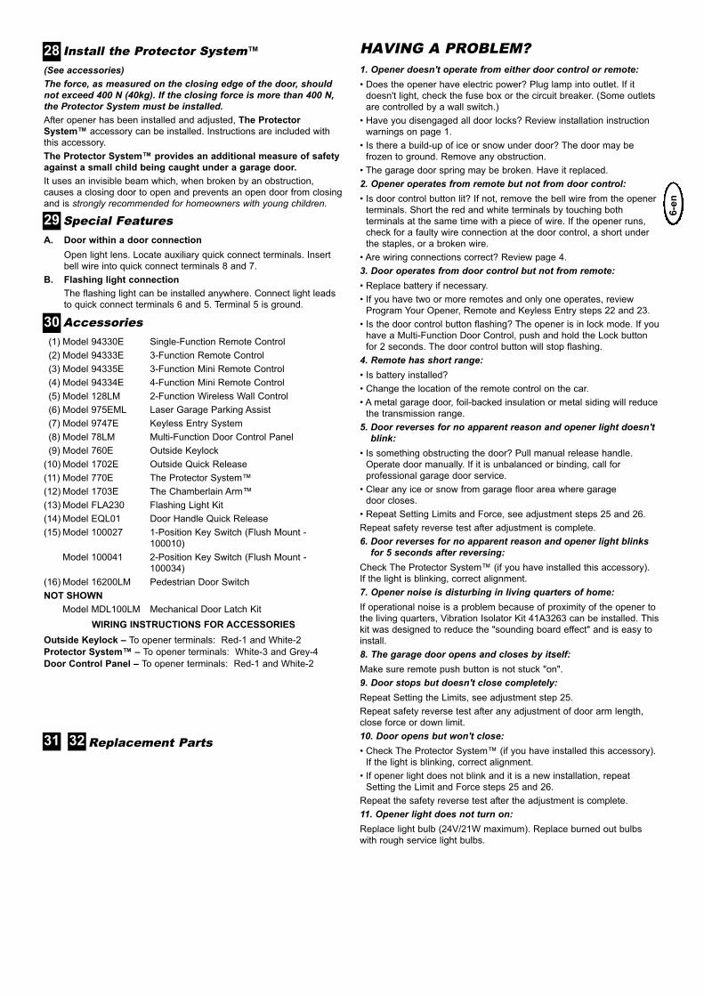
Accessories(1) Model 94330E Single-Function Remote Control
(2) Model 94333E 3-Function Remote Control
(3) Model 94335E 3-Function Mini Remote Control
(4) Model 94334E 4-Function Mini Remote Control
(5) Model 128LM 2-Function Wireless Wall Control
(6) Model 975EML Laser Garage Parking Assist
(7) Model 9747E Keyless Entry System
(8) Model 78LM Multi-Function Door Control Panel
(9) Model 760E Outside Keylock
(10) Model 1702E Outside Quick Release
(11) Model 770E The Protector System™
(12) Model 1703E The Chamberlain Arm™
(13) Model FLA230 Flashing Light Kit
(14) Model EQL01 Door Handle Quick Release
(15) Model 100027 1-Position Key Switch (Flush Mount -
100010)
Model 100041 2-Position Key Switch (Flush Mount -
100034)
(16) Model 16200LM Pedestrian Door Switch
NOT SHOWN
Model MDL100LM Mechanical Door Latch Kit
WIRING INSTRUCTIONS FOR ACCESSORIES
Outside Keylock – To opener terminals: Red-1 and White-2
Protector System™ – To opener terminals: White-3 and Grey-4
Door Control Panel – To opener terminals: Red-1 and White-2
30
Replacement Parts31 32
HAVING A PROBLEM?1. Opener doesn't operate from either door control or remote:• Does the opener have electric power? Plug lamp into outlet. If it
doesn't light, check the fuse box or the circuit breaker. (Some outlets
are controlled by a wall switch.)
• Have you disengaged all door locks? Review installation instruction
warnings on page 1.
• Is there a build-up of ice or snow under door? The door may be
frozen to ground. Remove any obstruction.
• The garage door spring may be broken. Have it replaced.
2. Opener operates from remote but not from door control:• Is door control button lit? If not, remove the bell wire from the opener
terminals. Short the red and white terminals by touching both
terminals at the same time with a piece of wire. If the opener runs,
check for a faulty wire connection at the door control, a short under
the staples, or a broken wire.
• Are wiring connections correct? Review page 4.
3. Door operates from door control but not from remote:• Replace battery if necessary.
• If you have two or more remotes and only one operates, review
Program Your Opener, Remote and Keyless Entry steps 22 and 23.
• Is the door control button flashing? The opener is in lock mode. If you
have a Multi-Function Door Control, push and hold the Lock button
for 2 seconds. The door control button will stop flashing.
4. Remote has short range:• Is battery installed?
• Change the location of the remote control on the car.
• A metal garage door, foil-backed insulation or metal siding will reduce
the transmission range.
5. Door reverses for no apparent reason and opener light doesn'tblink:
• Is something obstructing the door? Pull manual release handle.
Operate door manually. If it is unbalanced or binding, call for
professional garage door service.
• Clear any ice or snow from garage floor area where garage
door closes.
• Repeat Setting Limits and Force, see adjustment steps 25 and 26.
Repeat safety reverse test after adjustment is complete.
6. Door reverses for no apparent reason and opener light blinksfor 5 seconds after reversing:
Check The Protector System™ (if you have installed this accessory).
If the light is blinking, correct alignment.
7. Opener noise is disturbing in living quarters of home:If operational noise is a problem because of proximity of the opener to
the living quarters, Vibration Isolator Kit 41A3263 can be installed. This
kit was designed to reduce the "sounding board effect" and is easy to
install.
8. The garage door opens and closes by itself:Make sure remote push button is not stuck "on".
9. Door stops but doesn't close completely:Repeat Setting the Limits, see adjustment step 25.
Repeat safety reverse test after any adjustment of door arm length,
close force or down limit.
10. Door opens but won't close:• Check The Protector System™ (if you have installed this accessory).
If the light is blinking, correct alignment.
• If opener light does not blink and it is a new installation, repeat
Setting the Limit and Force steps 25 and 26.
Repeat the safety reverse test after the adjustment is complete.
11. Opener light does not turn on:Replace light bulb (24V/21W maximum). Replace burned out bulbs
with rough service light bulbs.

7-e
n
12. Opener strains:Door may be unbalanced or springs are broken. Close door and use
manual release rope and handle to disconnect trolley. Open and close
door manually. A properly balanced door will stay in any point of travel
while being supported entirely by its springs. If it does not, call for
professional garage door service to correct the problem.
13. Opener motor hums briefly, then won't work:• Garage door springs are broken. SEE ABOVE.
• If problem occurs on first operation of opener, door is locked. Disable
door lock.
Repeat safety reverse test after adjustment is complete.
14. Opener won't activate due to power failure:• Pull manual release rope and handle down to disconnect trolley.
Door can be opened and closed manually. When the power is
restored, pull the manual release handle straight back. The next time
the opener is activated, the trolley will reconnect.
• The Outside Quick Release accessory (if fitted) disconnects the
trolley from outside the garage in case of power failure.
15. Setting the limits manually:1. Press and hold the black button until the yellow indicator light starts
flashing slowly then release.
2. Push and hold the black button until the door reaches the desired
UP (open) position. Adjust the position of the door by using the
black and orange buttons. Black moves the door UP (open) and
orange moves the door DOWN (close).
Check to be sure the door opens high enough for your vehicle.
3. Push the remote control or door control. This sets the UP (open)
limit and begins closing the door. Immediately press either the
orange or the black button. The door will stop.
Adjust the desired DOWN (close) limit position using the black and
orange buttons. Check to be sure the door is fully closed without
applying excessive pressure on the rail (rail should not bow
upwards and the chain/belt should not sag or droop below the rail).
Push the remote control or door control. This sets the DOWN
(close) limit and begins opening the door.
NOTE: If neither the black or the orange button is pressed before thedoor reaches the floor, the GDO will attempt an Automated LimitSetting, reversing the door off the floor and stopping at the set Uplimit. If the worklight does not blink 10 times, limits setting has beensuccessful and doesn't need to be manually done; the DOWN limit willbe set to the floor.Regardless of setting the limits automatically or manually, theforce MUST be learned in order to properly complete the settingof limits. Refer to section 26, Setting the Force.4. Open and close the door with the remote control or door control 2
or 3 times.
• If the door does not stop in the desired UP (open) position or
reverses before the door stops at the DOWN (close) position,
repeat Setting the Limits manually one more time.
• If the door stops in both the desired UP (open) and DOWN (close)
positions, proceed to Test the Safety Reversal System.
Once a Month:
• Repeat safety reverse test. Make any necessary adjustments.
• Manually operate door. If it is unbalanced or binding, call for
professional garage door service.
• Check to be sure door opens and closes fully. Set Limits and/or
Force if necessary.
Once a Year:
Oil door rollers, bearings and hinges. The opener does not require
additional lubrication. Do not grease the door tracks. Grease rail and
trolley once a year.
When properly installed, opener will provide high performance with
a minimum of maintenance. The opener does not require additional
lubrication.
Limit and Force Settings: These settings must be checked and
properly set when opener is installed. Weather conditions may cause
some minor changes in the door operation, requiring some
re-adjustments, particularly during the first year of operation.Refer to Setting the Limits and Force on page 5. Follow the
instructions carefully and repeat the safety reverse test after
any adjustment.
Remote Control: The remote control may be secured to a car sun
visor with the clip provided. Additional remotes can be purchased at
any time for use in all vehicles using garage. Refer to Accessories.
Any new remotes must be programmed into the opener.
Remote Control Battery: The lithium batteries should produce power
for up to 5 years. If transmission range lessens, replace battery.
To Change Battery: To replace batteries, use the visor clip or
screwdriver blade to pry open the case. Insert batteries positive sideup. To replace cover, snap shut along both sides. Do not dispose of
the old battery with household waste. Take batteries to a proper
disposal center.
MAINTENANCE OF YOUR OPENER
CARE OF YOUR OPENERHAVING A PROBLEM? (CONT.)

8-e
n
OPERATION OF YOUR OPENERYour opener can be activated by any of the following devices:
• The Lighted Door Control Button. Hold the button down until door
starts to move.
• The Outside Keylock or Keyless Entry System (if you have
installed either of these accessories).
• The Remote Control Transmitter. Hold the push button down until
the door starts to move.
Opening the Door Manually:
Door should be fully closed if possible. Weak or broken springs
could allow an open door to fall rapidly. Property damage or
serious personal injury could result.
The door can be opened manually by pulling the release handle down
and back (toward the opener). To reconnect the door, pull the release
handle straight down.
Do not use the manual release handle to pull the door opener
or closed.
When the Opener is Activated by Remote Control or Lighted Door
Control Button:
1. If open, the door will close. If closed, the door will open.
2. If closing, the door will stop.
3. If opening, the door will stop (allowing space for entry and exit of
pets and for fresh air).
4. If the door has been stopped in a partially open or closed position, it
will reverse direction.
5. If an obstruction is encountered while closing, the door will reverse.
6. If an obstruction is encountered while opening, the door will reverse
and stop.
7. The optional Protector System™ uses an invisible beam which,
when broken by an obstruction, causes a closing door to open
and prevents an open door from closing. It is STRONGLY
RECOMMENDED for homeowners with young children.
Allow a 15 minute cooling period after 5 continuous operations
of the opener.
The opener light will turn on: 1. when opener is initially plugged in;
2. when the power is briefly interrupted; 3. when the opener is
activated.
The light turns off automatically after 2-1/2 minutes. Bulb size is
24V/21W maximum.
Input Voltage...................230-240 VAC, 50Hz
Max. Pull Force ..............600N (LM60), 800N (LM80)
Power .............................100W (LM60), 125W (LM80)
Standby Power ...............2,6W (LM60), 2,8W (LM80)
Normal Torque ................5Nm (LM60), 8Nm (LM80)
Motor
Type................................DC gearmotor permanent lubrication
Noise level ......................55dB
Drive Mechanism
Drive ...............................Chain/belt with two-piece trolley on
steel rail.
Length of Travel..............Adjustable to 2,3m (7-1/2 feet)
Travel Rate .....................5"-7" (127-178mm) per second
Lamp...............................On when door starts, off 2-1/2 minutes
after stop.
Door Linkage ..................Adjustable door arm. Pull cord trolley release.
Safety
Personal .........................Push button and automatic stop in down
direction. Push button and automatic stop in
up direction.
Electronic ........................Automatic force adjustment
Electrical .........................Transformer overload protector and low
voltage push button wiring.
Limit Device ....................Optical RPM/Passpoint detector.
Limit Adjustment .............Electronic, Semi and Fully Automatic.
Start Circuit .....................Low voltage push button circuit.
Dimensions
Length (Overall)..............3,2m (122-1/2")
Headroom Required .......30mm
Hanging Weight ..............14,5kg (32 lb)
Receiver
Memory Registers ..........12
Operating Frequency......433.92MHz
SPECIAL NOTE: Chamberlain strongly recommends that the protectorsystem be installed on all garage door openers.
SPECIFICATIONS
GARAGE DOOR OPENER WARRANTY
Chamberlain GmbH warrants to the first retail purchaser of this product (LM60;LM80) that theproduct shall be free from any defect in materials and/or workmanship for a period of 24 fullmonths (2 years) from the date of purchase. Upon receipt of the product, the first retailpurchaser is under obligation to check the product for any visible defects. Conditions: The warranty is strictly limited to the reparation or replacement of the parts ofthis product which are found to be defective and does not cover the costs or risks oftransportation of the defective parts or product.This warranty does not cover non-defect damage caused by unreasonable use (including usenot in complete accordance with Chamberlain’s instructions for installation, operation andcare; failure to provide necessary maintenance and adjustment; or any adaptations of oralterations to the products), labor charges for dismantling or reinstalling of a repaired orreplaced unit or replacement batteries.A product under warranty which is determined to be defective in materials and/orworkmanship will be repaired or replaced (at Chamberlain's option) at no cost to the owner forthe repair and/or replacement parts and/or product. Defective parts will be repaired orreplaced with new or factory rebuilt parts at Chamberlain's option.If, during the warranty period, the product appears as though it may be defective, contact youroriginal place of purchase.This warranty does not affect the purchaser’s statutory rights under applicable nationallegislation in force nor the purchaser’s rights against the retailer arising from theirsales/purchase contract. In the absence of applicable national or EU legislation, this warrantywill be the purchaser’s sole and exclusive remedy, and neither Chamberlain nor its affiliates ordistributors shall be liable for any incidental or consequential damages for any express orimplied warranty relating to this product.No representative or person is authorized to assume for Chamberlain any other liability inconnection with the sale of this product
GB Dec la ra t ion o f Con fo rmi ty
The undersigned, hereby declare that the equipment specified, and all accessories, conforms to the Directives and Standards stated.
Model:...........................................................................................................LM60, LM80
2004/108/EC
2006/95/EC
1999/5/EC
EN55014-1 (2000), EN55014-2 (1997), EN61000-3-2 (2000), EN61000-3-3 (1995), EN 301 489-3 (V1.3.1), EN 300 220-3 (V1.1.1), EN60335-1 (1994), and EN60335-2-95 (2004)
D ec la r a t ion o f I ncor por a t ionA power door operator, in combination with a Garage Door must be installed andmaintained according to all the Manufacturer’s instructions, to meet the provisions ofEN12453, EN13241-1 and Machinery Directive, 2006/42//EEC.
B. P. KelkhoffManager, Regulatory AffairsChamberlain GmbHD-66793 SaarwellingenApril, 2010


114A2805E-en © 2010, Chamberlain GmbH