Embed Size (px)
Citation preview

Product
Folder
Order
Now
Technical
Documents
Tools &
Software
Support &Community
An IMPORTANT NOTICE at the end of this data sheet addresses availability, warranty, changes, use in safety-critical applications,intellectual property matters and other important disclaimers. PRODUCTION DATA.
LM2574, LM2574HVSNVS104E –JUNE 1999–REVISED JULY 2018
LM2574x SIMPLE SWITCHER® 0.5-A Step-Down Voltage Regulator
1
1 Features1• 3.3-V, 5-V, 12-V, 15-V, and Adjustable Output
Versions• Adjustable Version Output Voltage Range: 1.23 V
to 37 V (57 V for HV version) ±4% Maximum OverLine and Load Conditions
• Specified 0.5-A Output Current• Wide Input Voltage Range: 40 V, up to 60 V for
HV Version• Requires Only 4 External Components• 52-kHz Fixed-Frequency Internal Oscillator• TTL Shutdown Capability, Low-Power Standby
Mode• High Efficiency• Uses Readily Available Standard Inductors• Thermal Shutdown and Current-Limit Protection• Create a Custom Design Using the LM2574 With
the WEBENCH® Power Designer
2 Applications• Simple High-Efficiency Step-Down (Buck)
Regulator• Efficient Preregulator for Linear Regulators• On-Card Switching Regulators• Positive-to-Negative Converter (Buck-Boost)
3 DescriptionThe LM2574xx series of regulators are monolithicintegrated circuits that provide all the active functionsfor a step-down (buck) switching regulator, capable ofdriving a 0.5-A load with excellent line and loadregulation. These devices are available in fixed outputvoltages of 3.3 V, 5 V, 12 V, 15 V, and an adjustableoutput version.
Requiring a minimum number of externalcomponents, these regulators are simple to use andinclude internal frequency compensation and a fixed-frequency oscillator.
The LM2574xx series offers a high-efficiencyreplacement for popular three-terminal linearregulators. Because of its high efficiency, the coppertraces on the printed-circuit board (PCB) are normallythe only heat sinking needed.
A standard series of inductors optimized for use withthe LM2574 are available from several differentmanufacturers. This feature greatly simplifies thedesign of switch-mode power supplies.
Other features include a specified ±4% tolerance onoutput voltage within specified input voltages andoutput load conditions, and ±10% on the oscillatorfrequency. External shutdown is included, featuring50-μA (typical) standby current. The output switchincludes cycle-by-cycle current limiting, as well asthermal shutdown for full protection under faultconditions.
Device Information(1)
PART NUMBER PACKAGE BODY SIZE (NOM)
LM2574, LM2574HVSOIC (14) 8.992 mm × 7.498 mmPDIP (8) 6.35 mm × 9.81 mm
(1) For all available packages, see the orderable addendum atthe end of the data sheet.
Typical Application (Fixed Output Voltage Versions)

2
LM2574, LM2574HVSNVS104E –JUNE 1999–REVISED JULY 2018 www.ti.com
Product Folder Links: LM2574 LM2574HV
Submit Documentation Feedback Copyright © 1999–2018, Texas Instruments Incorporated
Table of Contents1 Features .................................................................. 12 Applications ........................................................... 13 Description ............................................................. 14 Revision History..................................................... 25 Pin Configuration and Functions ......................... 36 Specifications......................................................... 4
6.1 Absolute Maximum Ratings ...................................... 46.2 ESD Ratings.............................................................. 46.3 Recommended Operating Conditions....................... 46.4 Thermal Information .................................................. 46.5 Electrical Characteristics for All Output Voltage
Versions ..................................................................... 56.6 Electrical Characteristics – 3.3-V Version................. 56.7 Electrical Characteristics – 5-V Version.................... 66.8 Electrical Characteristics – 12-V Version.................. 66.9 Electrical Characteristics – 15-V Version.................. 66.10 Electrical Characteristics – Adjustable Version....... 76.11 Typical Characteristics ............................................ 8
7 Detailed Description ............................................ 117.1 Overview ................................................................. 117.2 Functional Block Diagram ....................................... 11
7.3 Feature Description................................................. 117.4 Device Functional Modes........................................ 13
8 Application and Implementation ........................ 148.1 Application Information............................................ 148.2 Typical Applications ................................................ 19
9 Power Supply Recommendations ...................... 2610 Layout................................................................... 26
10.1 Layout Guidelines ................................................. 2610.2 Layout Example .................................................... 2710.3 Grounding ............................................................. 2710.4 Thermal Considerations ........................................ 27
11 Device and Documentation Support ................. 2911.1 Device Support...................................................... 2911.2 Documentation Support ........................................ 3111.3 Receiving Notification of Documentation Updates 3111.4 Community Resources.......................................... 3111.5 Trademarks ........................................................... 3111.6 Electrostatic Discharge Caution............................ 3111.7 Glossary ................................................................ 31
12 Mechanical, Packaging, and OrderableInformation ........................................................... 31
4 Revision History
Changes from Revision D (April 2016) to Revision E Page
• Added links for WEBENCH ................................................................................................................................................... 1• maximum supply voltage in Abs Max Ratings from "4.5" to "45" to correct typo ................................................................... 4
Changes from Revision C (April 2013) to Revision D Page
• Added Device Information table, ESD Ratings table, Feature Description section, Device Functional Modes,Application and Implementation section, Power Supply Recommendations section, Layout section, Device andDocumentation Support section, and Mechanical, Packaging, and Orderable Information section ..................................... 1
• Changed RθJA value in SOIC column to 77.1 ........................................................................................................................ 4• Split test conditions row of the Electrical Characteristics table to include TJ = 25°C and TJ < 25°C MIN, TYP, and
MAX values............................................................................................................................................................................. 5• Split test conditions in IL row to rearrange the MIN, TYP, and MAX values ......................................................................... 5
Changes from Revision B (November 2004) to Revision C Page
• Changed layout of National Data Sheet to TI format ............................................................................................................. 1

1NC 14 NC
2NC 13 NC
3FB 12 OUTPUT
4SIG_GND 11 NC
5ON/OFF 10 VIN
6PWR_GND 9 NC
7NC 8 NC
1FB 8 NC
2SIG_GND 7 OUTPUT
3ON/OFF 6 NC
4PWR_GND 5 VIN
3
LM2574, LM2574HVwww.ti.com SNVS104E –JUNE 1999–REVISED JULY 2018
Product Folder Links: LM2574 LM2574HV
Submit Documentation FeedbackCopyright © 1999–2018, Texas Instruments Incorporated
5 Pin Configuration and Functions
P Package8-Pin PDIPTop View
NPA Package14-Pin SOIC
Top View
Pin FunctionsPIN
I/O DESCRIPTIONNAME PDIP SOIC
FB 1 3 IFeedback sense input pin. Connect to the midpoint of feedback divider to setVOUT for ADJ version or connect this pin directly to the output capacitor for afixed output version.
NC 8, 6 1, 2, 7, 8, 9,11, 13, 14 — No internal connection, but must be soldered to PCB for best heat transfer.
ON/OFF 3 5 I Enable input to the voltage regulator. High = OFF and low = ON. Connect toGND to enable the voltage regulator. Do not leave this pin float.
OUTPUT 7 12 O Emitter pin of the power transistor. This is a switching node. Attached this pinto an inductor and the cathode of the external diode.
PWR_GND 4 6 — Power ground pins. Connect to system ground and SIF GND, ground pins ofCIN and COUT. Path to CIN must be as short as possible.
SIG_GND 2 4 — Signal ground pin. Ground reference for internal references and logic. Connectto system ground.
VIN 5 10 ISupply input pin to collector pin of high-side transistor. Connect to powersupply and input bypass capacitors CIN. Path from VIN pin to high frequencybypass CIN and PWR GND must be as short as possible.
4
LM2574, LM2574HVSNVS104E –JUNE 1999–REVISED JULY 2018 www.ti.com
Product Folder Links: LM2574 LM2574HV
Submit Documentation Feedback Copyright © 1999–2018, Texas Instruments Incorporated
(1) Stresses beyond those listed under Absolute Maximum Ratings may cause permanent damage to the device. These are stress ratingsonly, which do not imply functional operation of the device at these or any other conditions beyond those indicated under RecommendedOperating Conditions. Exposure to absolute-maximum-rated conditions for extended periods may affect device reliability.
6 Specifications
6.1 Absolute Maximum Ratingsover operating free-air temperature range (unless otherwise noted) (1)
MIN MAX UNIT
Maximum supply voltageLM2574 45
VLM2574HV 63
ON/OFF pin input voltage –0.3 VIN VOutput voltage to ground, steady-state –1 VPower dissipation Internally limitedLead temperature, soldering (10 s) 260 °CMaximum junction temperature 150 °CStorage temperature, Tstg –65 150 °C
(1) JEDEC document JEP155 states that 500-V HBM allows safe manufacturing with a standard ESD control process.
6.2 ESD RatingsVALUE UNIT
V(ESD) Electrostatic discharge Human-body model (HBM), per ANSI/ESDA/JEDEC JS-001 (1) ±2000 V
6.3 Recommended Operating Conditionsover operating free-air temperature range (unless otherwise noted)
MIN NOM MAX UNIT
Supply voltageLM2574 40
VLM2574HV 60
TJ Temperature –40 125 °C
(1) For more information about traditional and new thermal metrics, see the Semiconductor and IC Package Thermal Metrics applicationreport.
(2) The package thermal impedance is calculated in accordance with JESD 51-7.(3) Thermal resistances were simulated on a 4-layer, JEDEC board.
6.4 Thermal Information
THERMAL METRIC (1) (2)LM2574, LM2574HV
UNITP (PDIP) NPA (SOIC)8 PINS 14 PINS
RθJA Junction-to-ambient thermal resistance (3) 60.4 77.1 °C/WRθJC(top) Junction-to-case (top) thermal resistance (3) 59.9 29.2 °C/WRθJB Junction-to-board thermal resistance (3) 37.9 33.3 °C/WψJT Junction-to-top characterization parameter 17.1 2 °C/WψJB Junction-to-board characterization parameter 37.7 32.8 °C/WRθJC(bot) Junction-to-case (bottom) thermal resistance (3) — — °C/W

5
LM2574, LM2574HVwww.ti.com SNVS104E –JUNE 1999–REVISED JULY 2018
Product Folder Links: LM2574 LM2574HV
Submit Documentation FeedbackCopyright © 1999–2018, Texas Instruments Incorporated
(1) All limits specified at room temperature TYP and MAX. All room temperature limits are 100% production tested. All limits at temperatureextremes are specified through correlation using standard Statistical Quality Control (SQC) methods. All limits are used to calculateAverage Outgoing Quality Level.
(2) The oscillator frequency reduces to approximately 18 kHz in the event of an output short or an overload which causes the regulatedoutput voltage to drop approximately 40% from the nominal output voltage. This self protection feature lowers the average powerdissipation of the IC by lowering the minimum duty cycle from 5% down to approximately 2% (see Figure 6).
(3) Output pin sourcing current. No diode, inductor or capacitor connected to output pin.(4) Feedback pin removed from output and connected to 0 V.(5) Feedback pin removed from output and connected to 12 V for the adjustable, 3.3-V, and 5-V versions, and 25 V for the 12-V and 15-V
versions, to force the output transistor OFF.(6) VIN = 40 V (60 V for high voltage version).
6.5 Electrical Characteristics for All Output Voltage VersionsTJ = 25°C, and MIN and MAX apply over full operating temperature range. VIN = 12 V for the 3.3-V, 5-V, and adjustableversion, VIN = 25 V for the 12-V version, and VIN = 30 V for the 15-V version, ILOAD = 100 mA (unless otherwise noted).
PARAMETER TEST CONDITIONS MIN (1) TYP MAX (1) UNIT
Ib Feedback bias current Adjustable versiononly, VOUT = 5 V
TJ = 25°C 50 100nA
–40°C < TJ < 125°C 500
fO Oscillator frequency See (2) TJ = 25°C 47 52 58kHz
–40°C < TJ < 125°C 42 63
VSAT Saturation voltage IOUT = 0.5 A (3) TJ = 25°C 0.9 1.2V
–40°C < TJ < 125°C 1.4DC Maximum duty cycle (ON) See (4) 93% 98%
ICL Current limit Peak current (2) (3) 0.7 1 1.6A
0.65 1.8
IL Current output leakageOutput = 0 V 2
mAOutput = –1 V (5) (6) 7.5 30
IQ Quiescent current See (5) 5 10 mAISTBY Standby quiescent current ON/OFF pin = 5 V (OFF) 50 200 μAON/OFF CONTROL (SEE Figure 27)
VIH
ON/OFF pin logic input levelVOUT = 0 V
TJ = 25°C 2.2 1.4V
–40°C < TJ < 125°C 2.4
VILVOUT = Nominal outputvoltage
TJ = 25°C 1.2 1V
–40°C < TJ < 125°C 0.8IH ON/OFF pin input current
ON/OFF pin = 5 V (OFF) 12 30 μAIIL ON/OFF pin = 0 V (ON) 0 10 μA
(1) Test Circuit in Figure 22 and Figure 27.(2) All limits specified at room temperature and at temperature extremes . All room temperature limits are 100% production tested. All limits
at temperature extremes are specified via correlation using standard Statistical Quality Control (SQC) methods. All limits are used tocalculate Average Outgoing Quality Level.
6.6 Electrical Characteristics – 3.3-V VersionTJ = 25°C, and all MIN and MAX apply over full operating temperature range (unless otherwise noted).
PARAMETER (1) TEST CONDITIONS MIN (2) TYP MAX (2) UNIT
VOUT Output voltage
VIN = 12 V, ILOAD = 100 mA 3.234 3.3 3.366
VLM2574, 4.75 V ≤ VIN ≤ 40 V,0.1 A ≤ ILOAD ≤ 0.5 A
TJ = 25°C 3.168 3.3 3.432−40°C ≤ TJ ≤ 125°C 3.135 3.465
LM2574HV, 4.75 V ≤ VIN ≤ 60 V,0.1 A ≤ ILOAD ≤ 0.5 A
TJ = 25°C 3.168 3.3 3.45−40°C ≤ TJ ≤ 125°C 3.135 3.482
η Efficiency VIN = 12 V, ILOAD = 0.5 A 72%

6
LM2574, LM2574HVSNVS104E –JUNE 1999–REVISED JULY 2018 www.ti.com
Product Folder Links: LM2574 LM2574HV
Submit Documentation Feedback Copyright © 1999–2018, Texas Instruments Incorporated
(1) Test circuit in Figure 22 and Figure 27.(2) All limits specified at room temperature TYP and MAX. All room temperature limits are 100% production tested. All limits at temperature
extremes are specified through correlation using standard Statistical Quality Control (SQC) methods. All limits are used to calculateAverage Outgoing Quality Level.
6.7 Electrical Characteristics – 5-V VersionTJ = 25°C, and all MIN and MAX apply over full operating temperature range (unless otherwise noted).
PARAMETER (1) TEST CONDITIONS MIN TYP (2) MAX (2) UNIT
VOUT Output voltage
VIN = 12 V, ILOAD = 100 mA 4.9 5 5.1
VLM2574, 7 V ≤ VIN ≤ 40 V,0.1 A ≤ ILOAD ≤ 0.5 A
TJ = 25°C 4.8 5 5.2−40°C ≤ TJ ≤ 125°C 4.75 5.25
LM2574HV, 7 V ≤ VIN ≤ 60 V,0.1 A ≤ ILOAD ≤ 0.5 A
TJ = 25°C 4.8 5 5.225−40°C ≤ TJ ≤ 125°C 4.75 5.275
η Efficiency VIN = 12 V, ILOAD = 0.5 A 77%
(1) Test circuit in Figure 22 and Figure 27.(2) All limits specified at room temperature TYP and MAX. All room temperature limits are 100% production tested. All limits at temperature
extremes are specified through correlation using standard Statistical Quality Control (SQC) methods. All limits are used to calculateAverage Outgoing Quality Level.
6.8 Electrical Characteristics – 12-V VersionTJ = 25°C, and all MIN and MAX apply over full operating temperature range (unless otherwise noted).
PARAMETER (1) CONDITIONS MIN TYP (2) MAX (2) UNIT
VOUT Output voltage
VIN = 25 V, ILOAD = 100 mA 11.76 12 12.24
VLM2574, 15 V ≤ VIN ≤ 40 V,0.1 A ≤ ILOAD ≤ 0.5 A
TJ = 25°C 11.52 12 12.48−40°C ≤ TJ ≤ 125°C 11.4 12.6
LM2574HV, 15 V ≤ VIN ≤ 60 V,0.1 A ≤ ILOAD ≤ 0.5 A
TJ = 25°C 11.52 12 12.54−40°C ≤ TJ ≤ 125°C 11.4 12.66
η Efficiency VIN = 15 V, ILOAD = 0.5 A 88%
(1) Test circuit in Figure 22 and Figure 27.(2) All limits specified at room temperature TYP and MAX. All room temperature limits are 100% production tested. All limits at temperature
extremes are specified through correlation using standard Statistical Quality Control (SQC) methods. All limits are used to calculateAverage Outgoing Quality Level.
6.9 Electrical Characteristics – 15-V VersionTJ = 25°C, and all MIN and MAX apply over full operating temperature range (unless otherwise noted).
PARAMETER (1) TEST CONDITIONS MIN TYP (2) MAX (2) UNIT
VOUT Output voltage
VIN = 30 V, ILOAD = 100 mA 14.7 15 15.3
VLM2574, 18 V ≤ VIN ≤ 40 V,0.1A ≤ ILOAD ≤ 0.5 A
TJ = 25°C 14.4 15 15.6−40°C ≤ TJ ≤ 125°C 14.25 15.75
LM2574HV, 18 V ≤ VIN ≤ 60 V,0.1 A ≤ ILOAD ≤ 0.5 A
TJ = 25°C 14.4 15 15.68−40°C ≤ TJ ≤ 125°C 14.25 15.83
η Efficiency VIN = 18 V, ILOAD = 0.5 A 88%

7
LM2574, LM2574HVwww.ti.com SNVS104E –JUNE 1999–REVISED JULY 2018
Product Folder Links: LM2574 LM2574HV
Submit Documentation FeedbackCopyright © 1999–2018, Texas Instruments Incorporated
(1) Test circuit in Figure 22 and Figure 27.(2) All limits specified at room temperature TYP and MAX. All room temperature limits are 100% production tested. All limits at temperature
extremes are specified through correlation using standard Statistical Quality Control (SQC) methods. All limits are used to calculateAverage Outgoing Quality Level.
6.10 Electrical Characteristics – Adjustable VersionTJ = 25°C, and all MIN and MAX apply over full operating temperature range. VIN = 12 V, ILOAD = 100 mA (unless otherwisenoted).
PARAMETER (1) TEST CONDITIONS MIN TYP (2) MAX (2) UNIT
VFB Feedback voltage
VIN = 12 V, ILOAD = 100 mA 1.217 1.23 1.243
V
LM2574, 7 V ≤ VIN ≤ 40 V,0.1 A ≤ ILOAD ≤ 0.5 A,VOUT programmed for 5 V
TJ = 25°C 1.193 1.23 1.267
−40°C ≤ TJ ≤ 125°C 1.18 1.28
LM2574HV, 7 V ≤ VIN ≤ 60 V,0.1 A ≤ ILOAD ≤ 0.5 A,VOUT programmed for 5 V
TJ = 25°C 1.193 1.23 1.273
−40°C ≤ TJ ≤ 125°C 1.18 1.286
η Efficiency VIN = 12 V, VOUT = 5 V, ILOAD = 0.5 A 77%

8
LM2574, LM2574HVSNVS104E –JUNE 1999–REVISED JULY 2018 www.ti.com
Product Folder Links: LM2574 LM2574HV
Submit Documentation Feedback Copyright © 1999–2018, Texas Instruments Incorporated
6.11 Typical CharacteristicsSee Figure 27.
Figure 1. Normalized Output Voltage Figure 2. Line Regulation
Figure 3. Dropout Voltage Figure 4. Current Limit
Figure 5. Supply Current Figure 6. Standby Quiescent Current

9
LM2574, LM2574HVwww.ti.com SNVS104E –JUNE 1999–REVISED JULY 2018
Product Folder Links: LM2574 LM2574HV
Submit Documentation FeedbackCopyright © 1999–2018, Texas Instruments Incorporated
Typical Characteristics (continued)See Figure 27.
Figure 7. Oscillator Frequency Figure 8. Switch Saturation Voltage
Figure 9. Efficiency Figure 10. Minimum Operating Voltage
Figure 11. Supply Current vs Duty Cycle Figure 12. Feedback Voltage vs Duty Cycle
10
LM2574, LM2574HVSNVS104E –JUNE 1999–REVISED JULY 2018 www.ti.com
Product Folder Links: LM2574 LM2574HV
Submit Documentation Feedback Copyright © 1999–2018, Texas Instruments Incorporated
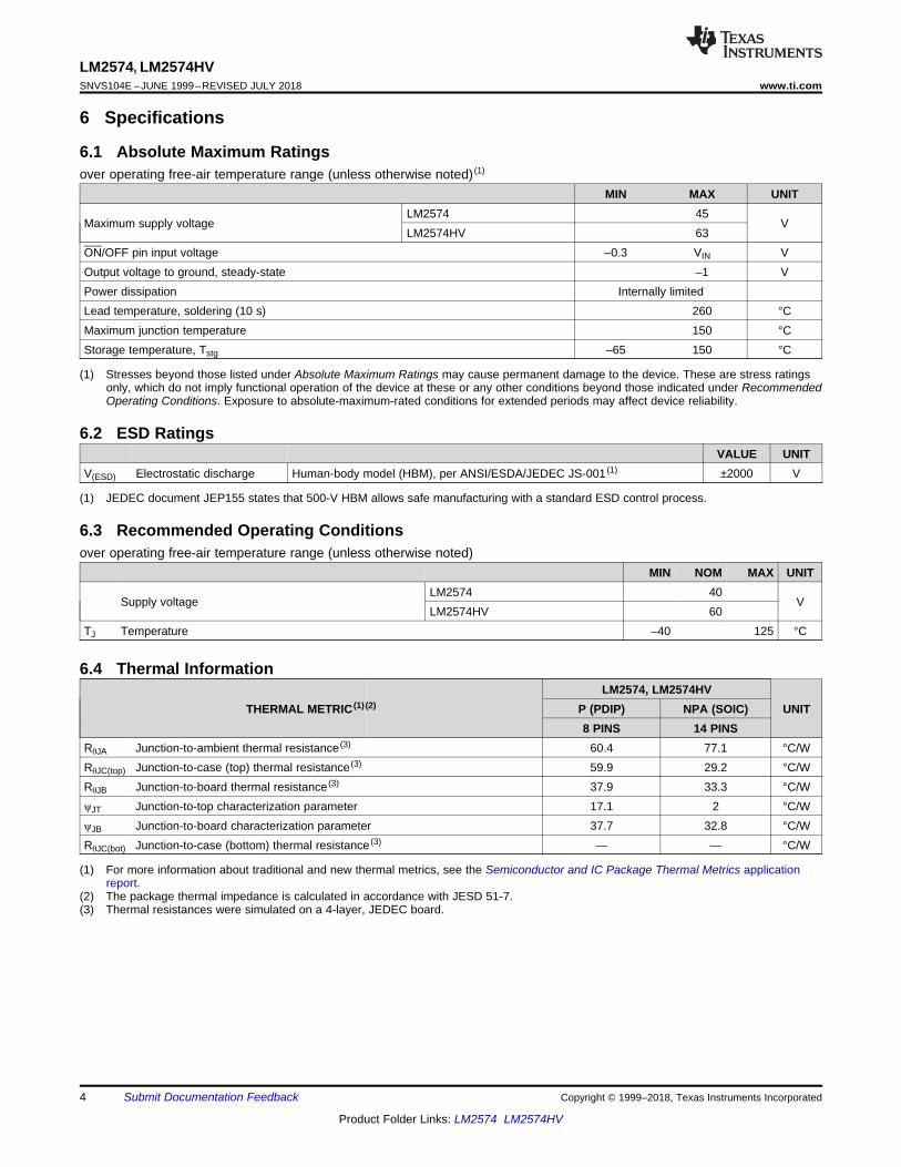
Typical Characteristics (continued)See Figure 27.
Figure 13. Feedback Pin Current Figure 14. Junction-to-Ambient Thermal Resistance

UnregulatedDC Input
Copyright © 2016, Texas Instruments Incorporated
CIN
+
2
Feedback1
5
VIN
Internal Regulator
ON / OFF
SignalGND
+
±
+
±
1.23 VBAND ± GAPREFRENCE Reset
ThermalShutdown
CurrentLimit
52 kHzOSCILLATOR
Compatator
Fixed GainError Amp
R2
R1
ON / OFF
0.5 Amp Switch
3
7
4
DRIVER
Pwr Gnd
Output+
COUTD1
L1
LOAD
VOUT
11
LM2574, LM2574HVwww.ti.com SNVS104E –JUNE 1999–REVISED JULY 2018
Product Folder Links: LM2574 LM2574HV
Submit Documentation FeedbackCopyright © 1999–2018, Texas Instruments Incorporated
7 Detailed Description
7.1 OverviewThe LM2574 SIMPLE SWITCHER® regulator is an easy-to-use, non-synchronous, step-down DC-DC converterwith a wide input voltage range from 40 V to up to 60 V for a HV version. It is capable of delivering up to 0.5-ADC load current with excellent line and load regulation. These devices are available in fixed output voltages of3.3 V, 5 V, 12 V, 15 V, and an adjustable output version. The family requires few external components and thepin arrangement was designed for simple, optimum PCB layout.
7.2 Functional Block Diagram
Note: Pin numbers are for the 8-pin PDIP packageR1 = 1 k3.3 V, R2 = 1.7 k5 V, R2 = 3.1 k12 V, R2 = 8.84 k15 V, R2 = 11.3 kFor adjustable version,R1 = Open, R2 = 0 Ω
7.3 Feature Description
7.3.1 Current LimitThe LM2574 device has current limiting to prevent the switch current from exceeding safe values during anaccidental overload on the output. This value (ICL) can be found in Electrical Characteristics for All OutputVoltage Versions.
7.3.2 Undervoltage LockoutIn some applications, it is desirable to keep the regulator off until the input voltage reaches a certain threshold.An undervoltage lockout circuit which accomplishes this task is shown in Figure 15 while Figure 16 shows thesame circuit applied to a buck-boost configuration. These circuits keep the regulator off until the input voltagereaches a predetermined level in Equation 1.
VTH ≈ VZ1 + 2 VBE (1)

12
LM2574, LM2574HVSNVS104E –JUNE 1999–REVISED JULY 2018 www.ti.com
Product Folder Links: LM2574 LM2574HV
Submit Documentation Feedback Copyright © 1999–2018, Texas Instruments Incorporated
Feature Description (continued)
Note: Complete circuit not shown (see Figure 20).Note: Pin numbers are for 8-pin PDIP package.
Figure 15. Undervoltage Lockout for Buck Circuit
Note: Complete circuit not shown (see Figure 20).Note: Pin numbers are for 8-pin PDIP package.
Figure 16. Undervoltage Lockout for Buck-Boost Circuit
7.3.3 Delayed Start-UpThe ON/OFF pin can be used to provide a delayed start-up feature as shown in Figure 17. With an input voltageof 20 V and for the part values shown, the circuit provides approximately 10 ms of delay time before the circuitbegins switching. Increasing the RC time constant can provide longer delay times. But excessively large RC timeconstants can cause problems with input voltages that are high in 60-Hz or 120-Hz ripple, by coupling the rippleinto the ON/OFF pin.
7.3.4 Adjustable Output, Low-Ripple Power SupplyA 500-mA power supply that features an adjustable output voltage is shown in Figure 18. An additional L-C filterthat reduces the output ripple by a factor of 10 or more is included in this circuit.

13
LM2574, LM2574HVwww.ti.com SNVS104E –JUNE 1999–REVISED JULY 2018
Product Folder Links: LM2574 LM2574HV
Submit Documentation FeedbackCopyright © 1999–2018, Texas Instruments Incorporated
Feature Description (continued)
Note: Complete circuit not shown.Note: Pin numbers are for 8-pin PDIP package.
Figure 17. Delayed Start-Up
Note: Pin numbers are for 8-pin PDIP package.
Figure 18. 1.2-V to 55-V Adjustable 500-mA Power Supply With Low-Output Ripple
7.4 Device Functional Modes
7.4.1 Shutdown ModeThe ON/OFF pin provides electrical ON and OFF control for the LM2574. When the voltage of this pin is higherthan 1.4 V, the device is shutdown mode. The typical standby current in this mode is 50 μA.
7.4.2 Active ModeWhen the voltage of the ON/OFF pin is below 1.2 V, the device starts switching and the output voltage rises untilit reaches a normal regulation voltage.
OUTON
OUT IN
Vt
T V V=
+
ON OUT
IN
t V
T V=
ONLOAD
t1.2 I
T´ ´
14
LM2574, LM2574HVSNVS104E –JUNE 1999–REVISED JULY 2018 www.ti.com
Product Folder Links: LM2574 LM2574HV
Submit Documentation Feedback Copyright © 1999–2018, Texas Instruments Incorporated
8 Application and Implementation
NOTEInformation in the following applications sections is not part of the TI componentspecification, and TI does not warrant its accuracy or completeness. TI’s customers areresponsible for determining suitability of components for their purposes. Customers shouldvalidate and test their design implementation to confirm system functionality.
8.1 Application Information
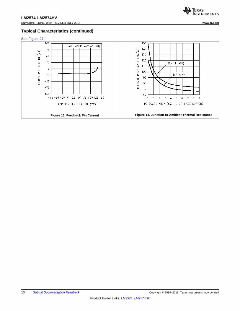
8.1.1 Input Capacitor (CIN)To maintain stability, the regulator input pin must be bypassed with at least a 22-μF electrolytic capacitor. Theleads of the capacitor must be kept short, and located near the regulator.
If the operating temperature range includes temperatures below −25°C, the input capacitor value may need to belarger. With most electrolytic capacitors, the capacitance value decreases and the ESR increases with lowertemperatures and age. Paralleling a ceramic or solid tantalum capacitor increases the regulator stability at coldtemperatures. For maximum capacitor operating lifetime, the RMS ripple current rating of the capacitor must begreater than Equation 2.
where
• for a buck regulator
• for a buck-boost regulator (2)
8.1.2 Inductor SelectionAll switching regulators have two basic modes of operation: continuous and discontinuous. The differencebetween the two types relates to the inductor current, whether it is flowing continuously, or if it drops to zero for aperiod of time in the normal switching cycle. Each mode has distinctively different operating characteristics,which can affect the regulator performance and requirements.
The LM2574 (or any of the SIMPLE SWITCHER family) can be used for both continuous and discontinuousmodes of operation.
In many cases the preferred mode of operation is in the continuous mode. It offers better load regulation, lowerpeak switch, inductor, and diode currents, and can have lower output ripple voltage. But it does require relativelylarge inductor values to keep the inductor current flowing continuously, especially at low output load currents.
To simplify the inductor selection process, an inductor selection guide (nomograph) was designed. This guideassumes continuous mode operation, and selects an inductor that allows a peak-to-peak inductor ripple current(ΔIIND) to be a certain percentage of the maximum design load current. In the LM2574 SIMPLE SWITCHER, thepeak-to-peak inductor ripple current percentage (of load current) is allowed to change as different design loadcurrents are selected. By allowing the percentage of inductor ripple current to increase for lower currentapplications, the inductor size and value can be kept relatively low.
8.1.3 Inductor Ripple CurrentWhen the switcher is operating in the continuous mode, the inductor current waveform ranges from a triangularto a sawtooth type of waveform (depending on the input voltage). For a given input voltage and output voltage,the peak-to-peak amplitude of this inductor current waveform remains constant. As the load current rises or falls,the entire sawtooth current waveform also rises or falls. The average DC value of this waveform is equal to theDC load current (in the buck regulator configuration).

INDI 212106 mA
2 2
D= = =
INDLOAD
I 212I 0.4 A 506 mA
2 2
Dæ ö æ ö= + = + =ç ÷ ç ÷
è øè ø
15
LM2574, LM2574HVwww.ti.com SNVS104E –JUNE 1999–REVISED JULY 2018
Product Folder Links: LM2574 LM2574HV
Submit Documentation FeedbackCopyright © 1999–2018, Texas Instruments Incorporated
Application Information (continued)If the load current drops to a low enough level, the bottom of the sawtooth current waveform reaches zero, andthe switcher changes to a discontinuous mode of operation. This is a perfectly acceptable mode of operation.Any buck switching regulator (no matter how large the inductor value is) is forced to run discontinuous if the loadcurrent is light enough.
The curve shown in Figure 19 illustrates how the peak-to-peak inductor ripple current (ΔIIND) is allowed to changeas different maximum load currents are selected, and also how it changes as the operating point varies from theupper border to the lower border within an inductance region (see Inductor Selection).
Figure 19. Inductor Ripple Current (ΔiIND) Range
Consider the following example:
VOUT = 5 V at 0.4 A
VIN = 10-V minimum up to 20-V maximum
The selection guide in Figure 24 shows that for a 0.4-A load current, and an input voltage range between 10 Vand 20 V, the inductance region selected by the guide is 330 μH. This value of inductance allows a peak-to-peakinductor ripple current (ΔIIND) to flow that is a percentage of the maximum load current. For this inductor value,the ΔIIND also varies depending on the input voltage. As the input voltage increases to 20 V, it approaches theupper border of the inductance region, and the inductor ripple current increases. Referring to the curve inFigure 19, it can be seen that at the 0.4-A load current level, and operating near the upper border of the 330-μHinductance region, the ΔIIND is 53% of 0.4 A, or 212 mAp-p.
This ΔIIND is important because from this number the peak inductor current rating can be determined, theminimum load current required before the circuit goes to discontinuous operation, and also, knowing the ESR ofthe output capacitor, the output ripple voltage can be calculated, or conversely, measuring the output ripplevoltage and knowing the ΔIIND, the ESR can be calculated.
From the previous example, the peak-to-peak inductor ripple current (ΔIIND) = 212 mAp-p. When the ΔIND value isknown, the following three formulas can be used to calculate additional information about the switching regulatorcircuit:1. Peak inductor or peak switch current in Equation 3.
(3)2. Minimum load current before the circuit becomes discontinuous in Equation 4.
(4)3. Output ripple voltage = (ΔIIND) × (ESR of COUT)

16
LM2574, LM2574HVSNVS104E –JUNE 1999–REVISED JULY 2018 www.ti.com
Product Folder Links: LM2574 LM2574HV
Submit Documentation Feedback Copyright © 1999–2018, Texas Instruments Incorporated
Application Information (continued)The selection guide chooses inductor values suitable for continuous mode operation, but if the inductor valuechosen is prohibitively high, the designer should investigate the possibility of discontinuous operation.
Inductors are available in different styles such as pot core, toroid, E-frame, bobbin core, and so forth, as well asdifferent core materials, such as ferrites and powdered iron. The least expensive, the bobbin core type, consistsof wire wrapped on a ferrite rod core. This type of construction makes for an inexpensive inductor, but becausethe magnetic flux is not completely contained within the core, it generates more electro-magnetic interference(EMI). This EMl can cause problems in sensitive circuits, or can give incorrect scope readings because ofinduced voltages in the scope probe.
The inductors listed in the selection chart include powdered iron toroid for Pulse Engineering, and ferrite bobbincore for Renco.
An inductor must not be operated beyond its maximum rated current because it may saturate. When an inductorbegins to saturate, the inductance decreases rapidly and the inductor begins to look mainly resistive (the DCresistance of the winding). This can cause the inductor current to rise very rapidly and affects the energy storagecapabilities of the inductor and could cause inductor overheating. Different inductor types have differentsaturation characteristics, and consider this when selecting an inductor. The inductor manufacturers' data sheetsinclude current and energy limits to avoid inductor saturation.
8.1.4 Output CapacitorAn output capacitor is required to filter the output voltage and is needed for loop stability. The capacitor must belocated near the LM2574 using short PCB traces. Standard aluminum electrolytics are usually adequate, but lowESR types are recommended for low output ripple voltage and good stability. The ESR of a capacitor dependson many factors, some which are: the value, the voltage rating, physical size, and the type of construction. Ingeneral, low-value or low-voltage (less than 12 V) electrolytic capacitors usually have higher ESR numbers.
The amount of output ripple voltage is primarily a function of the equivalent series resistance (ESR ) of the outputcapacitor and the amplitude of the inductor ripple current, ΔIIND (see Inductor Ripple Current (ΔiIND)).
The lower capacitor values (100 μF to 330 μF) allows typically 50 mV to 150 mV of output ripple voltage, whilelarger-value capacitors reduce the ripple to approximately 20 mV to 50 mV (as seen in Equation 5).
Output Ripple Voltage = (ΔIIND) (ESR of COUT) (5)
To further reduce the output ripple voltage, several standard electrolytic capacitors may be paralleled, or ahigher-grade capacitor may be used. Such capacitors are often called high-frequency, low-inductance, or low-ESR. These reduce the output ripple to 10 mV or 20 mV. However, when operating in the continuous mode,reducing the ESR below 0.03 Ω can cause instability in the regulator.
Tantalum capacitors can have a very low ESR, and must be carefully evaluated if it is the only output capacitor.Because of their good low temperature characteristics, a tantalum can be used in parallel with aluminumelectrolytics, with the tantalum making up 10% or 20% of the total capacitance.
The ripple current rating of the capacitor at 52 kHz must be at least 50% higher than the peak-to-peak inductorripple current.
8.1.5 Catch DiodeBuck regulators require a diode to provide a return path for the inductor current when the switch is off. This diodemust be located close to the LM2574 using short leads and short printed-circuit traces.
Because of their fast switching speed and low forward voltage drop, Schottky diodes provide the best efficiency,especially in low output voltage switching regulators (less than 5 V). fast-recovery, high-efficiency, or ultra-fastrecovery diodes are also suitable, but some types with an abrupt turnoff characteristic may cause instability andEMI problems. A fast-recovery diode with soft recovery characteristics is a better choice. Standard 60-Hz diodes(for example, 1N4001 or 1N5400, and so forth) are also not suitable. See Table 1 for Schottky and soft fast-recovery diode selection guide.

17
LM2574, LM2574HVwww.ti.com SNVS104E –JUNE 1999–REVISED JULY 2018
Product Folder Links: LM2574 LM2574HV
Submit Documentation FeedbackCopyright © 1999–2018, Texas Instruments Incorporated
Table 1. Diode Selection Guide
VR1-A DIODES
SCHOTTKY FAST RECOVERY
20 V1N5817SR102
MBR120P
30 V
1N5818SR103
11DQ03MBR130P10JQ030
The following diodes are all rated to 100 V
11DF110JF1
MUR110HER102
40 V
1N5819SR104
11DQ0411JQ04
MBR140P
50 V
MBR150SR105
11DQ0511JQ05
60 V
MBR160SR106
11DQ0611JQ06
90 V 11DQ09
8.1.6 Output Voltage Ripple and TransientsThe output voltage of a switching power supply contains a sawtooth ripple voltage at the switcher frequency,typically about 1% of the output voltage, and may also contain short voltage spikes at the peaks of the sawtoothwaveform.
The output ripple voltage is due mainly to the inductor sawtooth ripple current multiplied by the ESR of the outputcapacitor (see Inductor Selection).
The voltage spikes are present because of the fast switching action of the output switch, and the parasiticinductance of the output filter capacitor. To minimize these voltage spikes, special low inductance capacitors canbe used, and their lead lengths must be kept short. Wiring inductance, stray capacitance, as well as the scopeprobe used to evaluate these transients, all contribute to the amplitude of these spikes.
An additional small LC filter (20 μH and 100 μF) can be added to the output (as shown in Figure 18) to furtherreduce the amount of output ripple and transients. A 10 × reduction in output ripple voltage and transients ispossible with this filter.
8.1.7 Feedback ConnectionThe LM2574 (fixed voltage versions) feedback pin must be wired to the output voltage point of the switchingpower supply. When using the adjustable version, physically locate both output voltage programming resistorsnear the LM2574 to avoid picking up unwanted noise. Avoid using resistors greater than 100 kΩ because of theincreased chance of noise pickup.
8.1.8 ON/OFF InputFor normal operation, the ON/OFF pin must be grounded or driven with a low-level TTL voltage (typically lessthan 1.6 V). To put the regulator into standby mode, drive this pin with a high-level TTL or CMOS signal. TheON/OFF pin can be safely pulled up to +VIN without a resistor in series with it. The ON/OFF pin must not be leftopen.

( )LOAD IN OUT IN OUT
P
IN IN OUT 1 OSC
I V V V V 1I
V V V 2 L f
´ + ´» + ´
+ ´ ´
18
LM2574, LM2574HVSNVS104E –JUNE 1999–REVISED JULY 2018 www.ti.com
Product Folder Links: LM2574 LM2574HV
Submit Documentation Feedback Copyright © 1999–2018, Texas Instruments Incorporated
8.1.9 Additional Applications
8.1.9.1 Inverting RegulatorFigure 20 shows a LM2574-12 in a buck-boost configuration to generate a negative 12-V output from a positiveinput voltage. This circuit bootstraps the ground pin of the regulator to the negative output voltage, then bygrounding the feedback pin, the regulator senses the inverted output voltage and regulates it to −12 V.
Note: Pin numbers are for the 8-pin PDIP package.
Figure 20. Inverting Buck-Boost Develops, 12 V
For an input voltage of 8 V or more, the maximum available output current in this configuration is approximately100 mA. At lighter loads, the minimum input voltage required drops to approximately 4.7 V.
The switch currents in this buck-boost configuration are higher than in the standard buck-mode design, thuslowering the available output current. Also, the start-up input current of the buck-boost converter is higher thanthe standard buck-mode regulator, and this may overload an input power source with a current limit less than0.6 A. Using a delayed turnon or an undervoltage lockout circuit (described in Negative Boost Regulator) wouldallow the input voltage to rise to a high enough level before the switcher would be allowed to turn on.
Because of the structural differences between the buck and the buck-boost regulator topologies, the designprocedure can not be used to select the inductor or the output capacitor. The recommended range of inductorvalues for the buck-boost design is between 68 μH and 220 μH, and the output capacitor values must be largerthan what is normally required for buck designs. Low-input voltages or high-output currents require a large valueoutput capacitor (in the thousands of micro Farads).
The peak inductor current, which is the same as the peak switch current, can be calculated from Equation 6.
where• fosc = 52 kHz. Under normal continuous inductor current operating conditions,• the minimum VIN represents the worst case. Select an inductor that is rated for the peak current anticipated.
(6)
Also, the maximum voltage appearing across the regulator is the absolute sum of the input and output voltage.For a −12-V output, the maximum input voltage for the LM2574 is 28 V, or 48 V for the LM2574HV.
8.1.9.2 Negative Boost RegulatorAnother variation on the buck-boost topology is the negative boost configuration. The circuit in Figure 21 acceptsan input voltage ranging from −5 V to −12 V and provides a regulated −12-V output. Input voltages greater than−12 V causes the output to rise greater than −12 V, but does not damage the regulator.

19
LM2574, LM2574HVwww.ti.com SNVS104E –JUNE 1999–REVISED JULY 2018
Product Folder Links: LM2574 LM2574HV
Submit Documentation FeedbackCopyright © 1999–2018, Texas Instruments Incorporated
Note: Pin numbers are for 8-pin PDIP package.
Figure 21. Negative Boost
Because of the boosting function of this type of regulator, the switch current is relatively high, especially at lowinput voltages. Output load current limitations are a result of the maximum current rating of the switch. Also,boost regulators can not provide current-limiting load protection in the event of a shorted load, so some othermeans (such as a fuse) may be necessary.
8.2 Typical Applications
8.2.1 Fixed Output Voltage Applications
CIN: 22 μF, 75 VAluminum electrolytic
COUT: 220 μF, 25 VAluminum electrolytic
D1: Schottky, 11DQ06L1: 330 μH, 52627
(for 5 V in, 3.3 V out, use100 μH, RL-1284-100)
R1: 2k, 0.1%R2: 6.12k, 0.1%
Figure 22. Fixed Output Voltage Versions

20
LM2574, LM2574HVSNVS104E –JUNE 1999–REVISED JULY 2018 www.ti.com
Product Folder Links: LM2574 LM2574HV
Submit Documentation Feedback Copyright © 1999–2018, Texas Instruments Incorporated
Typical Applications (continued)8.2.1.1 Design RequirementsThe design requirements for the fixed output voltage application is provided in Table 2.
Table 2. Design ParametersPARAMETER EXAMPLE VALUE
Regulated output voltage (3.3 V, 5 V, 12 V, or 15 V), VOUT 5 VMaximum input voltage, VIN(Max) 15 VMaximum load current, ILOAD(Max) 0.4 A
8.2.1.2 Detailed Design Procedure
8.2.1.2.1 Custom Design With WEBENCH® Tools
Click here to create a custom design using the LM2574 device with the WEBENCH® Power Designer.1. Start by entering the input voltage (VIN), output voltage (VOUT), and output current (IOUT) requirements.2. Optimize the design for key parameters such as efficiency, footprint, and cost using the optimizer dial.3. Compare the generated design with other possible solutions from Texas Instruments.
The WEBENCH Power Designer provides a customized schematic along with a list of materials with real-timepricing and component availability.
In most cases, these actions are available:• Run electrical simulations to see important waveforms and circuit performance• Run thermal simulations to understand board thermal performance• Export customized schematic and layout into popular CAD formats• Print PDF reports for the design, and share the design with colleagues
Get more information about WEBENCH tools at www.ti.com/WEBENCH.
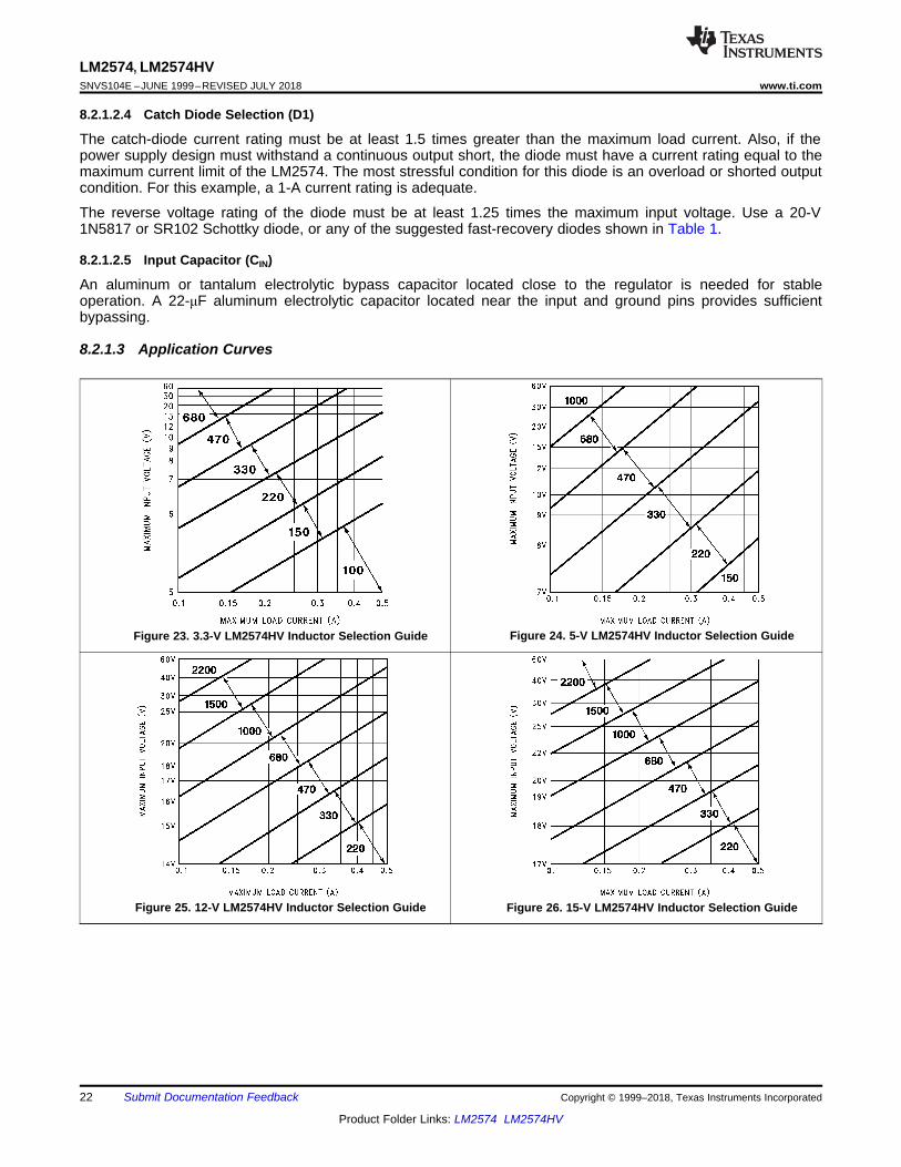
8.2.1.2.2 Inductor Selection (L1)
Select the correct Inductor value selection guide from Figure 23, Figure 24, Figure 25, or Figure 26 (outputvoltages of 3.3 V, 5 V, 12 V, or 15 V respectively).
From the inductor value selection guide, identify the inductance region intersected by VIN(Max) and ILOAD(Max).The inductance area intersected by the 15-V line and 0.4-A line is 330.
Select an appropriate inductor from Table 3. Part numbers are listed for three inductor manufacturers. Theinductor chosen must be rated for operation at the LM2574 switching frequency (52 kHz) and for a current ratingof 1.5 × ILOAD. For additional inductor information, see Inductor Selection. The required inductor value is 330 μH.From Table 3, choose Pulse Engineering PE-52627, Renco RL-1284-330, or NPI NP5920/5921.

21
LM2574, LM2574HVwww.ti.com SNVS104E –JUNE 1999–REVISED JULY 2018
Product Folder Links: LM2574 LM2574HV
Submit Documentation FeedbackCopyright © 1999–2018, Texas Instruments Incorporated
Table 3. Inductor Selection By Manufacturer's Part NumberINDUCTOR VALUE PULSE ENG. RENCO NPI
68 μH * RL-1284-68-43 NP5915100 μH * RL-1284-100-43 NP5916150 μH 52625 RL-1284-150-43 NP5917220 μH 52626 RL-1284-220-43 NP5918/5919330 μH 52627 RL-1284-330-43 NP5920/5921470 μH 52628 RL-1284-470-43 NP5922680 μH 52629 RL-1283-680-43 NP59231000 μH 52631 RL-1283-1000-43 *1500 μH * RL-1283-1500-43 *2200 μH * RL-1283-2200-43 *
8.2.1.2.3 Output Capacitor Selection (COUT)
The value of the output capacitor together with the inductor defines the dominate pole-pair of the switchingregulator loop. For stable operation and an acceptable output ripple voltage, (approximately 1% of the outputvoltage) a value between 100 μF and 470 μF is recommended. COUT = 100-μF to 470-μF standard aluminumelectrolytic.
The voltage rating of the capacitor must be at least 1.5 times greater than the output voltage. For a 5-V regulator,a rating of at least 8 V is appropriate, and a 10-V or 15-V rating is recommended. Capacitor voltage rating =20 V.
Higher voltage electrolytic capacitors generally have lower ESR numbers, and for this reason it may benecessary to select a capacitor rated for a higher voltage than would normally be needed.
22
LM2574, LM2574HVSNVS104E –JUNE 1999–REVISED JULY 2018 www.ti.com
Product Folder Links: LM2574 LM2574HV
Submit Documentation Feedback Copyright © 1999–2018, Texas Instruments Incorporated
8.2.1.2.4 Catch Diode Selection (D1)
The catch-diode current rating must be at least 1.5 times greater than the maximum load current. Also, if thepower supply design must withstand a continuous output short, the diode must have a current rating equal to themaximum current limit of the LM2574. The most stressful condition for this diode is an overload or shorted outputcondition. For this example, a 1-A current rating is adequate.
The reverse voltage rating of the diode must be at least 1.25 times the maximum input voltage. Use a 20-V1N5817 or SR102 Schottky diode, or any of the suggested fast-recovery diodes shown in Table 1.
8.2.1.2.5 Input Capacitor (CIN)
An aluminum or tantalum electrolytic bypass capacitor located close to the regulator is needed for stableoperation. A 22-μF aluminum electrolytic capacitor located near the input and ground pins provides sufficientbypassing.
8.2.1.3 Application Curves
Figure 23. 3.3-V LM2574HV Inductor Selection Guide Figure 24. 5-V LM2574HV Inductor Selection Guide
Figure 25. 12-V LM2574HV Inductor Selection Guide Figure 26. 15-V LM2574HV Inductor Selection Guide

OUT2 1
REF
V 24 VR R 1 1k 1
V 1.23 V
æ ö æ ö= ´ - = ´ -ç ÷ ç ÷
è øè ø
2OUT
1
RV 1.23 1
R
æ ö= ´ +ç ÷
è ø
OUT2 1
REF
VR R 1
V
æ ö= ´ -ç ÷
è ø
2OUT REF
1
RV V 1
R
æ ö= ´ +ç ÷
è ø
23
LM2574, LM2574HVwww.ti.com SNVS104E –JUNE 1999–REVISED JULY 2018
Product Folder Links: LM2574 LM2574HV
Submit Documentation FeedbackCopyright © 1999–2018, Texas Instruments Incorporated
8.2.2 Adjustable Output Voltage Applications
Figure 27. Adjustable Output Voltage Version
8.2.2.1 Design RequirementsThe design requirements for the fixed output voltage application is provided in Table 4.
Table 4. Design ParametersPARAMETER EXAMPLE VALUE
Regulated output voltage, VOUT 24 VMaximum input voltage, VIN(Max) 40 VMaximum load current, ILOAD(Max) 0.4 A
Switching frequency, F 52 kHz
8.2.2.2 Detailed Design Procedure
8.2.2.2.1 Programming Output Voltage
Selecting R1 and R2, as shown in Figure 27.
Use Equation 7 to select the appropriate resistor values.
where• VREF = 1.23 V (7)
R1 can be between 1k and 5k as in Equation 8. For best temperature coefficient and stability with time, use 1%metal film resistors.
(8)
For this example, use Equation 9 and Equation 10.
select• R1 = 1k (9)
(10)
R2 = 1k (19.51−1) = 18.51k, closest 1% value is 18.7k

OUT
40C 13300 22.2 µF
24 1000> ´ =
´
( )
( )( )
IN MAX
OUTOUT
VC 13300 µF
V L µH³ ´
´
( )24 1000
E T 40 24 185 V µs40 52
´ = - ´ ´ = ´
( )( )
( )OUTIN OUT
IN
V 1000E T V V V µs
V F kHz´ = - ´ ´ ´
24
LM2574, LM2574HVSNVS104E –JUNE 1999–REVISED JULY 2018 www.ti.com
Product Folder Links: LM2574 LM2574HV
Submit Documentation Feedback Copyright © 1999–2018, Texas Instruments Incorporated
8.2.2.2.2 Inductor Selection (L1)
Calculate the inductor Volt × microsecond constant, E × T (V × μs), from Equation 11.
(11)
For this example, calculate E × T (V × μs) using Equation 12.
(12)
Use the E × T value from the previous formula and match it with the E × T number on the vertical axis of theinductor value selection guide shown in Figure 32. For this example, E × T = 185 V × μs.
On the horizontal axis, select the maximum load current, ILOAD(Max) = 0.4 A.
Identify the inductance region intersected by the E × T value and the maximum load current value, and note theinductor value for that region, inductance region = 1000.
Select an appropriate inductor from the table shown in Table 3. Part numbers are listed for three inductormanufacturers. The inductor chosen must be rated for operation at the LM2574 switching frequency (52 kHz) andfor a current rating of 1.5 × ILOAD. For additional inductor information, see Inductor Selection.
8.2.2.2.3 Output Capacitor Selection (COUT)
The value of the output capacitor together with the inductor defines the dominate pole-pair of the switchingregulator loop. For stable operation, the capacitor must satisfy the requirement in Equation 13.
(13)
Equation 13 yields capacitor values between 5 μF and 1000 μF that satisfies the loop requirements for stableoperation. But to achieve an acceptable output ripple voltage, (approximately 1% of the output voltage) andtransient response, the output capacitor may need to be several times larger than the above formula yields.
The voltage rating of the capacitor must be at last 1.5 times greater than the output voltage. For a 24-V regulator,a rating of at least 35 V is recommended. Higher voltage electrolytic capacitors generally have lower ESRnumbers, and for this reasion it may be necessary to select a capacitor rate for a higher voltage than wouldnormally be needed.
(14)
However, for acceptable output ripple voltage select:
COUT ≥ 100 μF
COUT = 100 μF electrolytic capacitor
8.2.2.2.4 Catch Diode Selection (D1)
The catch-diode current rating must be at least 1.5 times greater than the maximum load current. Also, if thepower supply design must withstand a continuous output short, the diode must have a current rating equal to themaximum current limit of the LM2574. The most stressful condition for this diode is an overload or shorted outputcondition. Suitable diodes are shown in Table 1. For this example, a 1-A current rating is adequate.
The reverse voltage rating of the diode must be at least 1.25 times the maximum input voltage. Use a 50-VMBR150 or 11DQ05 Schottky diode, or any of the suggested fast-recovery diodes in Table 1.
8.2.2.2.5 Input Capacitor (CIN)
An aluminum or tantalum electrolytic bypass capacitor located close to the regulator is needed for stableoperation. A 22-μF aluminum electrolytic capacitor located near the input and ground pins provides sufficientbypassing (see Table 1).

25
LM2574, LM2574HVwww.ti.com SNVS104E –JUNE 1999–REVISED JULY 2018
Product Folder Links: LM2574 LM2574HV
Submit Documentation FeedbackCopyright © 1999–2018, Texas Instruments Incorporated
8.2.2.3 Application Curves
Output pin voltage, 10 V/div, Horizontal time base,Inductor current, 0.2 A/div, 5 μs/div,Output ripple voltage, VOUT = 5 V,20 mV/div, 500-mA load current,AC-coupled L = 330 Μh
Figure 28. Continuous Mode Switching Waveforms
Output pin voltage, 10 V/div, Horizontal time base,Inductor current, 0.2 A/div, 5 μs/div,Output ripple voltage, VOUT = 5 V,20 mV/div, 100-mA load current,AC-coupled L = 100 Μh
Figure 29. Discontinuous Mode Switching Waveforms
Output voltage, 50 V/div, 500 mA load,AC-coupled, L = 330 Μh,100-mA to 500-mA load pulse, COUT = 300 Μf,Horizontal time base: 200 μs/div
Figure 30. Transient Response forContinuous Mode Operation
Output voltage, 50 V/div, 250 mA load,AC-coupled, L = 68 Μh,50-mA to 250-mA load pulse, COUT = 470 Μf,Horizontal time base: 200 μs/div
Figure 31. Transient Response forDiscontinuous Mode Operation
Figure 32. Adjustable LM2574HV Inductor Selection Guide

26
LM2574, LM2574HVSNVS104E –JUNE 1999–REVISED JULY 2018 www.ti.com
Product Folder Links: LM2574 LM2574HV
Submit Documentation Feedback Copyright © 1999–2018, Texas Instruments Incorporated
9 Power Supply RecommendationsAs in any switching regulator, layout is very important. Rapidly switching currents associated with wiringinductance generate voltage transients which can cause problems. For minimal inductance and ground loops, thelength of the leads indicated by heavy lines must be kept as short as possible. Single-point grounding (asindicated) or ground plane construction must be used for best results. When using the adjustable version,physically locate the programming resistors near the regulator, to keep the sensitive feedback wiring short.
10 Layout
10.1 Layout GuidelinesThe layout is critical for the proper operation of switching power supplies. First, the ground plane area must besufficient for thermal dissipation purposes. Second, appropriate guidelines must be followed to reduce the effectsof switching noise. Switch mode converters are very fast switching devices. In such cases, the rapid increase ofinput current combined with the parasitic trace inductance generates unwanted L di/dt noise spikes. Themagnitude of this noise tends to increase as the output current increases. This noise may turn intoelectromagnetic interference (EMI) and can also cause problems in device performance. Therefore, take care inthe layout to minimize the effect of this switching noise.
The most important layout rule is to keep the AC current loops as small as possible. Figure 33 shows the currentflow in a buck converter. The top schematic shows a dotted line which represents the current flow during the topswitch ON-state. The middle schematic shows the current flow during the top switch OFF-state. The bottomschematic shows the currents referred to as AC currents. These AC currents are the most critical because theyare changing in a very short time period. The dotted lines of the bottom schematic are the traces to keep as shortand wide as possible. This also yields a small loop area reducing the loop inductance. To avoid functionalproblems due to layout, review the PCB layout example. Best results are achieved if the placement of theLM2574 device, the bypass capacitor, the Schottky diode, RFBB, RFBT, and the inductor are placed as shown inthe example. In the layout shown, R1 = RFBB and R2 = RFBT. TI also recommends using 2-oz. copper boardsor heavier to help thermal dissipation and to reduce the parasitic inductances of board traces. See the applicationnote AN-1229 SIMPLE SWITCHER® PCB Layout Guidelines (SNVA054) for more information.
Figure 33. Buck Converter Current Flow

27
LM2574, LM2574HVwww.ti.com SNVS104E –JUNE 1999–REVISED JULY 2018
Product Folder Links: LM2574 LM2574HV
Submit Documentation FeedbackCopyright © 1999–2018, Texas Instruments Incorporated
10.2 Layout Example
Figure 34. LM2574 Adjustable Output Voltage Layout
10.3 GroundingThe 8-pin molded PDIP and the 14-pin SOIC package have separate power and signal ground pins. Both groundpins must be soldered directly to wide printed-circuit board copper traces to assure low inductance connectionsand good thermal properties.
10.4 Thermal ConsiderationsThe 8-pin PDIP (P) package and the 14-pin SOIC (NPA) package are molded plastic packages with solid copperlead frames. The copper lead frame conducts the majority of the heat from the die, through the leads, to theprinted-circuit board copper, which acts as the heat sink. For best thermal performance, wide copper traces mustbe used, and all ground and unused pins must be soldered to generous amounts of printed-circuit board copper,such as a ground plane. Large areas of copper provide the best transfer of heat (lower thermal resistance) to thesurrounding air, and even double-sided or multilayer boards provide better heat paths to the surrounding air.Unless the power levels are small, using a socket for the 8-pin package is not recommended because of theadditional thermal resistance it introduces, and the resultant higher junction temperature.
Because of the 0.5-A current rating of the LM2574, the total package power dissipation for this switcher is quitelow, ranging from approximately 0.1 W up to 0.75 W under varying conditions. In a carefully engineered printed-circuit board, both the P and the NPA package can easily dissipate up to 0.75 W, even at ambient temperaturesof 60°C, and still keep the maximum junction temperature less than 125°C.
A curve, Figure 14, displaying thermal resistance versus PCB area for the two packages is shown in TypicalCharacteristics.
These thermal resistance numbers are approximate, and there can be many factors that affect the final thermalresistance. Some of these factors include board size, shape, thickness, position, location, and boardtemperature. Other factors are, the area of printed-circuit copper, copper thickness, trace width, multi-layer,single- or double-sided, and the amount of solder on the board. The effectiveness of the PCB to dissipate heatalso depends on the size, number and spacing of other components on the board. Furthermore, some of thesecomponents, such as the catch diode and inductor generate some additional heat. Also, the thermal resistancedecreases as the power level increases because of the increased air current activity at the higher power levels,and the lower surface to air resistance coefficient at higher temperatures.
The data sheet thermal resistance curves can estimate the maximum junction temperature based on operatingconditions. ln addition, the junction temperature can be estimated in actual circuit operation by usingEquation 15.
Tj = Tcu + (θj-cu × PD) (15)

OUTD IN S LOAD SAT
IN
VP V I I V
V= ´ + ´ ´
28
LM2574, LM2574HVSNVS104E –JUNE 1999–REVISED JULY 2018 www.ti.com
Product Folder Links: LM2574 LM2574HV
Submit Documentation Feedback Copyright © 1999–2018, Texas Instruments Incorporated
Thermal Considerations (continued)With the switcher operating under worst case conditions and all other components on the board in the intendedenclosure, measure the copper temperature (Tcu ) near the IC. This can be done by temporarily soldering a smallthermocouple to the PCB copper near the IC, or by holding a small thermocouple on the PCB copper usingthermal grease for good thermal conduction.
The thermal resistance (θj-cu) for the two packages is:
θj-cu = 42°C/W for the P-8 package
θj-cu = 52°C/W for the NPA-14 package
The power dissipation (PD) for the IC could be measured, or it can be estimated by using Equation 16.
where• IS is obtained from the typical supply current curve (adjustable version use the supply current vs duty cycle
curve) (16)

OUT OUT
IN OUT LOSS
P P
P P Ph = =
+
OUTON
OUT IN
VtD
T V V= =
+
ON OUT
IN
t VD
T V= =
29
LM2574, LM2574HVwww.ti.com SNVS104E –JUNE 1999–REVISED JULY 2018
Product Folder Links: LM2574 LM2574HV
Submit Documentation FeedbackCopyright © 1999–2018, Texas Instruments Incorporated
11 Device and Documentation Support
11.1 Device Support
11.1.1 Third-Party Products DisclaimerTI'S PUBLICATION OF INFORMATION REGARDING THIRD-PARTY PRODUCTS OR SERVICES DOES NOTCONSTITUTE AN ENDORSEMENT REGARDING THE SUITABILITY OF SUCH PRODUCTS OR SERVICESOR A WARRANTY, REPRESENTATION OR ENDORSEMENT OF SUCH PRODUCTS OR SERVICES, EITHERALONE OR IN COMBINATION WITH ANY TI PRODUCT OR SERVICE.
11.1.2 Custom Design With WEBENCH® ToolsClick here to create a custom design using the LM2574 device with the WEBENCH® Power Designer.1. Start by entering the input voltage (VIN), output voltage (VOUT), and output current (IOUT) requirements.2. Optimize the design for key parameters such as efficiency, footprint, and cost using the optimizer dial.3. Compare the generated design with other possible solutions from Texas Instruments.
The WEBENCH Power Designer provides a customized schematic along with a list of materials with real-timepricing and component availability.
In most cases, these actions are available:• Run electrical simulations to see important waveforms and circuit performance• Run thermal simulations to understand board thermal performance• Export customized schematic and layout into popular CAD formats• Print PDF reports for the design, and share the design with colleagues
Get more information about WEBENCH tools at www.ti.com/WEBENCH.
11.1.3 Device Nomenclature
11.1.3.1 Buck RegulatorA switching regulator topology in which a higher voltage is converted to a lower voltage. Also known as a step-down switching regulator.
11.1.3.2 Buck-Boost RegulatorA switching regulator topology in which a positive voltage is converted to a negative voltage without atransformer.
11.1.3.3 Duty Cycle (D)The ratio of the ON-time of the output switch to the oscillator period calculated with Equation 17 for buckregulators and Equation 18 for buck-boost regulators.
(17)
(18)
11.1.3.4 Catch Diode or Current Steering DiodeThis diode provides a return path for the load current when the LM2574 switch is OFF.
In terms of efficiency (η), the proportion of input power actually delivered to the load calculated with Equation 19.
(19)

30
LM2574, LM2574HVSNVS104E –JUNE 1999–REVISED JULY 2018 www.ti.com
Product Folder Links: LM2574 LM2574HV
Submit Documentation Feedback Copyright © 1999–2018, Texas Instruments Incorporated
Device Support (continued)11.1.3.5 Capacitor Equivalent Series Resistance (ESR)The purely resistive component of a real capacitor's impedance (see Figure 35) can causes power loss resultingin capacitor heating, which directly affects the operating lifetime of the capacitor. When used as a switchingregulator output filter, higher ESR values result in higher output ripple voltages.
Figure 35. Simple Model Of A Real Capacitor
Most standard aluminum electrolytic capacitors in the 100 μF to 1000 μF range have 0.5-Ω to 0.1-Ω ESR. Higher-grade capacitors (low-ESR, high-frequency, or low-inductance) in the 100 μF to 1000 μF range generally haveESR of less than 0.15 Ω.
11.1.3.6 Equivalent Series Inductance (ESL)The pure inductance component of a capacitor is seen in Figure 35. The amount of inductance is determined to alarge extent on the capacitor's construction. In a buck regulator, this unwanted inductance causes voltage spikesto appear on the output.
11.1.3.7 Output Ripple VoltageThe AC component of the output voltage of the switching regulator is usually dominated by the output capacitor'sESR multiplied by the inductor's ripple current (ΔIIND). The peak-to-peak value of this sawtooth ripple current canbe determined by reading Inductor Ripple Current (ΔiIND).
11.1.3.8 Capacitor Ripple CurrentThe RMS value of the maximum allowable alternating current at which a capacitor can be operated continuouslyat a specified temperature.
11.1.3.9 Standby Quiescent Current (ISTBY)Supply current required by the LM2574 when in the standby mode (ON/OFF pin is driven to TTL-high voltage,thus turning the output switch OFF).
11.1.3.10 Inductor Ripple Current (ΔiIND)The peak-to-peak value of the inductor current waveform, typically a sawtooth waveform when the regulator isoperating in the continuous mode (vs. discontinuous mode).
11.1.3.11 Continuous and Discontinuous Mode OperationThese mode operations relate to the inductor current. In the continuous mode, the inductor current is alwaysflowing and never drops to zero, versus the discontinuous mode, where the inductor current drops to zero for aperiod of time in the normal switching cycle.
11.1.3.12 Inductor SaturationThe condition which exists when an inductor cannot hold any more magnetic flux. When an inductor saturates,the inductor appears less inductive and the resistive component dominates. Inductor current is then limited onlyby the DC resistance of the wire and the available source current.
11.1.3.13 Operating Volt Microsecond Constant (E × Top)The product (in VoIt × μs) of the voltage applied to the inductor and the time the voltage is applied. This E × Topconstant is a measure of the energy handling capability of an inductor and is dependent upon the type of core,the core area, the number of turns, and the duty cycle.

31
LM2574, LM2574HVwww.ti.com SNVS104E –JUNE 1999–REVISED JULY 2018
Product Folder Links: LM2574 LM2574HV
Submit Documentation FeedbackCopyright © 1999–2018, Texas Instruments Incorporated
11.2 Documentation Support
11.2.1 Related DocumentationFor related documentation see the following:
AN-1229 SIMPLE SWITCHER® PCB Layout Guidelines, SNVA054
11.3 Receiving Notification of Documentation UpdatesTo receive notification of documentation updates, navigate to the device product folder on ti.com. In the upperright corner, click on Alert me to register and receive a weekly digest of any product information that haschanged. For change details, review the revision history included in any revised document.
11.4 Community ResourcesThe following links connect to TI community resources. Linked contents are provided "AS IS" by the respectivecontributors. They do not constitute TI specifications and do not necessarily reflect TI's views; see TI's Terms ofUse.
TI E2E™ Online Community TI's Engineer-to-Engineer (E2E) Community. Created to foster collaborationamong engineers. At e2e.ti.com, you can ask questions, share knowledge, explore ideas and helpsolve problems with fellow engineers.
Design Support TI's Design Support Quickly find helpful E2E forums along with design support tools andcontact information for technical support.
11.5 TrademarksE2E is a trademark of Texas Instruments.WEBENCH, SIMPLE SWITCHER are registered trademarks of Texas Instruments.All other trademarks are the property of their respective owners.
11.6 Electrostatic Discharge CautionThese devices have limited built-in ESD protection. The leads should be shorted together or the device placed in conductive foamduring storage or handling to prevent electrostatic damage to the MOS gates.
11.7 GlossarySLYZ022 — TI Glossary.
This glossary lists and explains terms, acronyms, and definitions.
12 Mechanical, Packaging, and Orderable InformationThe following pages include mechanical, packaging, and orderable information. This information is the mostcurrent data available for the designated devices. This data is subject to change without notice and revision ofthis document. For browser-based versions of this data sheet, refer to the left-hand navigation.
PACKAGE OPTION ADDENDUM
www.ti.com 23-Jul-2018
Addendum-Page 1
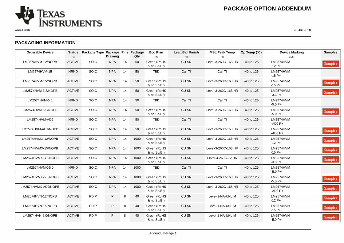
PACKAGING INFORMATION
Orderable Device Status(1)
Package Type PackageDrawing
Pins PackageQty
Eco Plan(2)
Lead/Ball Finish(6)
MSL Peak Temp(3)
Op Temp (°C) Device Marking(4/5)
Samples
LM2574HVM-12/NOPB ACTIVE SOIC NPA 14 50 Green (RoHS& no Sb/Br)
CU SN Level-3-260C-168 HR -40 to 125 LM2574HVM-12 P+
LM2574HVM-15 NRND SOIC NPA 14 50 TBD Call TI Call TI -40 to 125 LM2574HVM-15 P+
LM2574HVM-15/NOPB ACTIVE SOIC NPA 14 50 Green (RoHS& no Sb/Br)
CU SN Level-3-260C-168 HR -40 to 125 LM2574HVM-15 P+
LM2574HVM-3.3/NOPB ACTIVE SOIC NPA 14 50 Green (RoHS& no Sb/Br)
CU SN Level-3-260C-168 HR -40 to 125 LM2574HVM-3.3 P+
LM2574HVM-5.0 NRND SOIC NPA 14 50 TBD Call TI Call TI -40 to 125 LM2574HVM-5.0 P+
LM2574HVM-5.0/NOPB ACTIVE SOIC NPA 14 50 Green (RoHS& no Sb/Br)
CU SN Level-3-260C-168 HR -40 to 125 LM2574HVM-5.0 P+
LM2574HVM-ADJ NRND SOIC NPA 14 50 TBD Call TI Call TI -40 to 125 LM2574HVM-ADJ P+
LM2574HVM-ADJ/NOPB ACTIVE SOIC NPA 14 50 Green (RoHS& no Sb/Br)
CU SN Level-3-260C-168 HR -40 to 125 LM2574HVM-ADJ P+
LM2574HVMX-12/NOPB ACTIVE SOIC NPA 14 1000 Green (RoHS& no Sb/Br)
CU SN Level-3-260C-168 HR -40 to 125 LM2574HVM-12 P+
LM2574HVMX-15/NOPB ACTIVE SOIC NPA 14 1000 Green (RoHS& no Sb/Br)
CU SN Level-3-260C-168 HR -40 to 125 LM2574HVM-15 P+
LM2574HVMX-3.3/NOPB ACTIVE SOIC NPA 14 1000 Green (RoHS& no Sb/Br)
CU SN Level-4-260C-72 HR -40 to 125 LM2574HVM-3.3 P+
LM2574HVMX-5.0 NRND SOIC NPA 14 1000 TBD Call TI Call TI -40 to 125 LM2574HVM-5.0 P+
LM2574HVMX-5.0/NOPB ACTIVE SOIC NPA 14 1000 Green (RoHS& no Sb/Br)
CU SN Level-3-260C-168 HR -40 to 125 LM2574HVM-5.0 P+
LM2574HVMX-ADJ/NOPB ACTIVE SOIC NPA 14 1000 Green (RoHS& no Sb/Br)
CU SN Level-3-260C-168 HR -40 to 125 LM2574HVM-ADJ P+
LM2574HVN-12/NOPB ACTIVE PDIP P 8 40 Green (RoHS& no Sb/Br)
CU SN Level-1-NA-UNLIM -40 to 125 LM2574HVN-12 P+
LM2574HVN-15/NOPB ACTIVE PDIP P 8 40 Green (RoHS& no Sb/Br)
CU SN Level-1-NA-UNLIM -40 to 125 LM2574HVN-15 P+
LM2574HVN-5.0/NOPB ACTIVE PDIP P 8 40 Green (RoHS& no Sb/Br)
CU SN Level-1-NA-UNLIM -40 to 125 LM2574HVN-5.0 P+

PACKAGE OPTION ADDENDUM
www.ti.com 23-Jul-2018
Addendum-Page 2
Orderable Device Status(1)
Package Type PackageDrawing
Pins PackageQty
Eco Plan(2)
Lead/Ball Finish(6)
MSL Peak Temp(3)
Op Temp (°C) Device Marking(4/5)
Samples
LM2574HVN-ADJ/NOPB ACTIVE PDIP P 8 40 Green (RoHS& no Sb/Br)
CU SN Level-1-NA-UNLIM -40 to 125 LM2574HVN-ADJ P+
LM2574M-12/NOPB ACTIVE SOIC NPA 14 50 Green (RoHS& no Sb/Br)
CU SN Level-3-260C-168 HR -40 to 125 LM2574M-12 P+
LM2574M-3.3/NOPB ACTIVE SOIC NPA 14 50 Green (RoHS& no Sb/Br)
CU SN Level-3-260C-168 HR -40 to 125 LM2574M-3.3 P+
LM2574M-5.0 NRND SOIC NPA 14 50 TBD Call TI Call TI -40 to 125 LM2574M-5.0 P+
LM2574M-5.0/NOPB ACTIVE SOIC NPA 14 50 Green (RoHS& no Sb/Br)
CU SN Level-3-260C-168 HR -40 to 125 LM2574M-5.0 P+
LM2574M-ADJ NRND SOIC NPA 14 50 TBD Call TI Call TI -40 to 125 LM2574M-ADJ P+
LM2574M-ADJ/NOPB ACTIVE SOIC NPA 14 50 Green (RoHS& no Sb/Br)
CU SN Level-3-260C-168 HR -40 to 125 LM2574M-ADJ P+
LM2574MX-12/NOPB ACTIVE SOIC NPA 14 1000 Green (RoHS& no Sb/Br)
CU SN Level-3-260C-168 HR -40 to 125 LM2574M-12 P+
LM2574MX-3.3/NOPB ACTIVE SOIC NPA 14 1000 Green (RoHS& no Sb/Br)
CU SN Level-4-260C-72 HR -40 to 125 LM2574M-3.3 P+
LM2574MX-5.0 NRND SOIC NPA 14 1000 TBD Call TI Call TI -40 to 125 LM2574M-5.0 P+
LM2574MX-5.0/NOPB ACTIVE SOIC NPA 14 1000 Green (RoHS& no Sb/Br)
CU SN Level-3-260C-168 HR -40 to 125 LM2574M-5.0 P+
LM2574MX-ADJ/NOPB ACTIVE SOIC NPA 14 1000 Green (RoHS& no Sb/Br)
CU SN Level-3-260C-168 HR -40 to 125 LM2574M-ADJ P+
LM2574N-12/NOPB ACTIVE PDIP P 8 40 Green (RoHS& no Sb/Br)
CU SN Level-1-NA-UNLIM -40 to 125 LM2574N-12 P+
LM2574N-3.3/NOPB ACTIVE PDIP P 8 40 Green (RoHS& no Sb/Br)
CU SN Level-1-NA-UNLIM -40 to 125 LM2574N-3.3 P+
LM2574N-5.0/NOPB ACTIVE PDIP P 8 40 Green (RoHS& no Sb/Br)
CU SN Level-1-NA-UNLIM -40 to 125 LM2574N-5.0 P+
LM2574N-ADJ/NOPB ACTIVE PDIP P 8 40 Green (RoHS& no Sb/Br)
CU SN Level-1-NA-UNLIM -40 to 125 LM2574N-ADJ P+
(1) The marketing status values are defined as follows:ACTIVE: Product device recommended for new designs.LIFEBUY: TI has announced that the device will be discontinued, and a lifetime-buy period is in effect.NRND: Not recommended for new designs. Device is in production to support existing customers, but TI does not recommend using this part in a new design.

PACKAGE OPTION ADDENDUM
www.ti.com 23-Jul-2018
Addendum-Page 3
PREVIEW: Device has been announced but is not in production. Samples may or may not be available.OBSOLETE: TI has discontinued the production of the device.
(2) RoHS: TI defines "RoHS" to mean semiconductor products that are compliant with the current EU RoHS requirements for all 10 RoHS substances, including the requirement that RoHS substancedo not exceed 0.1% by weight in homogeneous materials. Where designed to be soldered at high temperatures, "RoHS" products are suitable for use in specified lead-free processes. TI mayreference these types of products as "Pb-Free".RoHS Exempt: TI defines "RoHS Exempt" to mean products that contain lead but are compliant with EU RoHS pursuant to a specific EU RoHS exemption.Green: TI defines "Green" to mean the content of Chlorine (Cl) and Bromine (Br) based flame retardants meet JS709B low halogen requirements of <=1000ppm threshold. Antimony trioxide basedflame retardants must also meet the <=1000ppm threshold requirement.
(3) MSL, Peak Temp. - The Moisture Sensitivity Level rating according to the JEDEC industry standard classifications, and peak solder temperature.
(4) There may be additional marking, which relates to the logo, the lot trace code information, or the environmental category on the device.
(5) Multiple Device Markings will be inside parentheses. Only one Device Marking contained in parentheses and separated by a "~" will appear on a device. If a line is indented then it is a continuationof the previous line and the two combined represent the entire Device Marking for that device.
(6) Lead/Ball Finish - Orderable Devices may have multiple material finish options. Finish options are separated by a vertical ruled line. Lead/Ball Finish values may wrap to two lines if the finishvalue exceeds the maximum column width.
Important Information and Disclaimer:The information provided on this page represents TI's knowledge and belief as of the date that it is provided. TI bases its knowledge and belief on informationprovided by third parties, and makes no representation or warranty as to the accuracy of such information. Efforts are underway to better integrate information from third parties. TI has taken andcontinues to take reasonable steps to provide representative and accurate information but may not have conducted destructive testing or chemical analysis on incoming materials and chemicals.TI and TI suppliers consider certain information to be proprietary, and thus CAS numbers and other limited information may not be available for release.
In no event shall TI's liability arising out of such information exceed the total purchase price of the TI part(s) at issue in this document sold by TI to Customer on an annual basis.

TAPE AND REEL INFORMATION
*All dimensions are nominal
Device PackageType
PackageDrawing
Pins SPQ ReelDiameter
(mm)
ReelWidth
W1 (mm)
A0(mm)
B0(mm)
K0(mm)
P1(mm)
W(mm)
Pin1Quadrant
LM2574HVMX-12/NOPB SOIC NPA 14 1000 330.0 16.4 10.9 9.5 3.2 12.0 16.0 Q1
LM2574HVMX-15/NOPB SOIC NPA 14 1000 330.0 16.4 10.9 9.5 3.2 12.0 16.0 Q1
LM2574HVMX-3.3/NOPB SOIC NPA 14 1000 330.0 16.4 10.9 9.5 3.2 12.0 16.0 Q1
LM2574HVMX-5.0 SOIC NPA 14 1000 330.0 16.4 10.9 9.5 3.2 12.0 16.0 Q1
LM2574HVMX-5.0/NOPB SOIC NPA 14 1000 330.0 16.4 10.9 9.5 3.2 12.0 16.0 Q1
LM2574HVMX-ADJ/NOPB SOIC NPA 14 1000 330.0 16.4 10.9 9.5 3.2 12.0 16.0 Q1
LM2574MX-12/NOPB SOIC NPA 14 1000 330.0 16.4 10.9 9.5 3.2 12.0 16.0 Q1
LM2574MX-3.3/NOPB SOIC NPA 14 1000 330.0 16.4 10.9 9.5 3.2 12.0 16.0 Q1
LM2574MX-5.0 SOIC NPA 14 1000 330.0 16.4 10.9 9.5 3.2 12.0 16.0 Q1
LM2574MX-5.0/NOPB SOIC NPA 14 1000 330.0 16.4 10.9 9.5 3.2 12.0 16.0 Q1
LM2574MX-ADJ/NOPB SOIC NPA 14 1000 330.0 16.4 10.9 9.5 3.2 12.0 16.0 Q1
PACKAGE MATERIALS INFORMATION
www.ti.com 23-Jul-2018
Pack Materials-Page 1

*All dimensions are nominal
Device Package Type Package Drawing Pins SPQ Length (mm) Width (mm) Height (mm)
LM2574HVMX-12/NOPB SOIC NPA 14 1000 367.0 367.0 38.0
LM2574HVMX-15/NOPB SOIC NPA 14 1000 367.0 367.0 38.0
LM2574HVMX-3.3/NOPB SOIC NPA 14 1000 367.0 367.0 38.0
LM2574HVMX-5.0 SOIC NPA 14 1000 367.0 367.0 38.0
LM2574HVMX-5.0/NOPB SOIC NPA 14 1000 367.0 367.0 38.0
LM2574HVMX-ADJ/NOPB SOIC NPA 14 1000 367.0 367.0 38.0
LM2574MX-12/NOPB SOIC NPA 14 1000 367.0 367.0 38.0
LM2574MX-3.3/NOPB SOIC NPA 14 1000 367.0 367.0 38.0
LM2574MX-5.0 SOIC NPA 14 1000 367.0 367.0 38.0
LM2574MX-5.0/NOPB SOIC NPA 14 1000 367.0 367.0 38.0
LM2574MX-ADJ/NOPB SOIC NPA 14 1000 367.0 367.0 38.0
PACKAGE MATERIALS INFORMATION
www.ti.com 23-Jul-2018
Pack Materials-Page 2

MECHANICAL DATA
NPA0014B
www.ti.com

IMPORTANT NOTICE
Texas Instruments Incorporated (TI) reserves the right to make corrections, enhancements, improvements and other changes to itssemiconductor products and services per JESD46, latest issue, and to discontinue any product or service per JESD48, latest issue. Buyersshould obtain the latest relevant information before placing orders and should verify that such information is current and complete.TI’s published terms of sale for semiconductor products (http://www.ti.com/sc/docs/stdterms.htm) apply to the sale of packaged integratedcircuit products that TI has qualified and released to market. Additional terms may apply to the use or sale of other types of TI products andservices.Reproduction of significant portions of TI information in TI data sheets is permissible only if reproduction is without alteration and isaccompanied by all associated warranties, conditions, limitations, and notices. TI is not responsible or liable for such reproduceddocumentation. Information of third parties may be subject to additional restrictions. Resale of TI products or services with statementsdifferent from or beyond the parameters stated by TI for that product or service voids all express and any implied warranties for theassociated TI product or service and is an unfair and deceptive business practice. TI is not responsible or liable for any such statements.Buyers and others who are developing systems that incorporate TI products (collectively, “Designers”) understand and agree that Designersremain responsible for using their independent analysis, evaluation and judgment in designing their applications and that Designers havefull and exclusive responsibility to assure the safety of Designers' applications and compliance of their applications (and of all TI productsused in or for Designers’ applications) with all applicable regulations, laws and other applicable requirements. Designer represents that, withrespect to their applications, Designer has all the necessary expertise to create and implement safeguards that (1) anticipate dangerousconsequences of failures, (2) monitor failures and their consequences, and (3) lessen the likelihood of failures that might cause harm andtake appropriate actions. Designer agrees that prior to using or distributing any applications that include TI products, Designer willthoroughly test such applications and the functionality of such TI products as used in such applications.TI’s provision of technical, application or other design advice, quality characterization, reliability data or other services or information,including, but not limited to, reference designs and materials relating to evaluation modules, (collectively, “TI Resources”) are intended toassist designers who are developing applications that incorporate TI products; by downloading, accessing or using TI Resources in anyway, Designer (individually or, if Designer is acting on behalf of a company, Designer’s company) agrees to use any particular TI Resourcesolely for this purpose and subject to the terms of this Notice.TI’s provision of TI Resources does not expand or otherwise alter TI’s applicable published warranties or warranty disclaimers for TIproducts, and no additional obligations or liabilities arise from TI providing such TI Resources. TI reserves the right to make corrections,enhancements, improvements and other changes to its TI Resources. TI has not conducted any testing other than that specificallydescribed in the published documentation for a particular TI Resource.Designer is authorized to use, copy and modify any individual TI Resource only in connection with the development of applications thatinclude the TI product(s) identified in such TI Resource. NO OTHER LICENSE, EXPRESS OR IMPLIED, BY ESTOPPEL OR OTHERWISETO ANY OTHER TI INTELLECTUAL PROPERTY RIGHT, AND NO LICENSE TO ANY TECHNOLOGY OR INTELLECTUAL PROPERTYRIGHT OF TI OR ANY THIRD PARTY IS GRANTED HEREIN, including but not limited to any patent right, copyright, mask work right, orother intellectual property right relating to any combination, machine, or process in which TI products or services are used. Informationregarding or referencing third-party products or services does not constitute a license to use such products or services, or a warranty orendorsement thereof. Use of TI Resources may require a license from a third party under the patents or other intellectual property of thethird party, or a license from TI under the patents or other intellectual property of TI.TI RESOURCES ARE PROVIDED “AS IS” AND WITH ALL FAULTS. TI DISCLAIMS ALL OTHER WARRANTIES ORREPRESENTATIONS, EXPRESS OR IMPLIED, REGARDING RESOURCES OR USE THEREOF, INCLUDING BUT NOT LIMITED TOACCURACY OR COMPLETENESS, TITLE, ANY EPIDEMIC FAILURE WARRANTY AND ANY IMPLIED WARRANTIES OFMERCHANTABILITY, FITNESS FOR A PARTICULAR PURPOSE, AND NON-INFRINGEMENT OF ANY THIRD PARTY INTELLECTUALPROPERTY RIGHTS. TI SHALL NOT BE LIABLE FOR AND SHALL NOT DEFEND OR INDEMNIFY DESIGNER AGAINST ANY CLAIM,INCLUDING BUT NOT LIMITED TO ANY INFRINGEMENT CLAIM THAT RELATES TO OR IS BASED ON ANY COMBINATION OFPRODUCTS EVEN IF DESCRIBED IN TI RESOURCES OR OTHERWISE. IN NO EVENT SHALL TI BE LIABLE FOR ANY ACTUAL,DIRECT, SPECIAL, COLLATERAL, INDIRECT, PUNITIVE, INCIDENTAL, CONSEQUENTIAL OR EXEMPLARY DAMAGES INCONNECTION WITH OR ARISING OUT OF TI RESOURCES OR USE THEREOF, AND REGARDLESS OF WHETHER TI HAS BEENADVISED OF THE POSSIBILITY OF SUCH DAMAGES.Unless TI has explicitly designated an individual product as meeting the requirements of a particular industry standard (e.g., ISO/TS 16949and ISO 26262), TI is not responsible for any failure to meet such industry standard requirements.Where TI specifically promotes products as facilitating functional safety or as compliant with industry functional safety standards, suchproducts are intended to help enable customers to design and create their own applications that meet applicable functional safety standardsand requirements. Using products in an application does not by itself establish any safety features in the application. Designers mustensure compliance with safety-related requirements and standards applicable to their applications. Designer may not use any TI products inlife-critical medical equipment unless authorized officers of the parties have executed a special contract specifically governing such use.Life-critical medical equipment is medical equipment where failure of such equipment would cause serious bodily injury or death (e.g., lifesupport, pacemakers, defibrillators, heart pumps, neurostimulators, and implantables). Such equipment includes, without limitation, allmedical devices identified by the U.S. Food and Drug Administration as Class III devices and equivalent classifications outside the U.S.TI may expressly designate certain products as completing a particular qualification (e.g., Q100, Military Grade, or Enhanced Product).Designers agree that it has the necessary expertise to select the product with the appropriate qualification designation for their applicationsand that proper product selection is at Designers’ own risk. Designers are solely responsible for compliance with all legal and regulatoryrequirements in connection with such selection.Designer will fully indemnify TI and its representatives against any damages, costs, losses, and/or liabilities arising out of Designer’s non-compliance with the terms and provisions of this Notice.
Mailing Address: Texas Instruments, Post Office Box 655303, Dallas, Texas 75265Copyright © 2018, Texas Instruments Incorporated