Embed Size (px)
Citation preview
LM 6000 – PC Technical Description
- 1 -
Table of Contents Table of Contents ........................................................................................................... 1
1. Unit’s Identity.................................................................................................................. 2
1.1 Gas Turbines’ Electronic Controls System ......................................................... 2
1.2 Main Equipment Technical Data ......................................................................... 2
2. Technical Description of Power Plant Equipment ................................................. 3
2.1 BOP Systems ..................................................................................................... 3
2.1.1 Water Treatment Plant ................................................................ 3
2.1.2 Instrument - Service Air System................................................... 4
2.1.3 Fire Protection System................................................................. 4
2.1.4 Liquid Fuel System (Diesel) ........................................................ 5
2.1.5 Gas Regulation Station (GRS) ..................................................... 5
2.1.6 Hot Water System ....................................................................... 5
2.1.7 Emergency Diesel Generator (EDG) ............................................ 6
2.1.8 Tanks........................................................................................... 6
2.1.9 Transformers ............................................................................... 6
3. Unit Auxiliary Systems .................................................................................................... 7
4. Photo Archive .............................................................................................................. 8-9
- 2 -
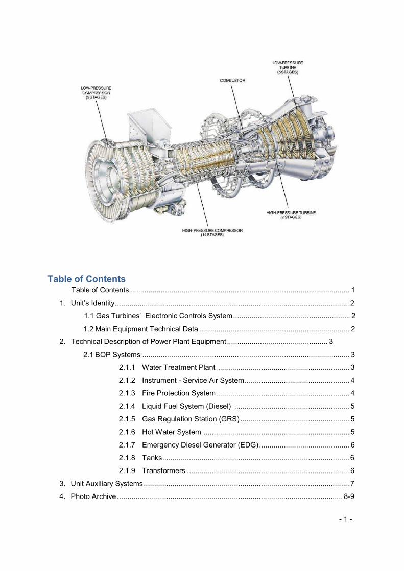
1. Units’ Identity
GT #1 GT #2 GT #3
Serial No 191507 191508 191516
Model (Type) LM6000-PC LM6000-PC LM6000-PC
Start Attempts 1104 1.049 1120
Gas Fired Starts 976 982 1011
Gas Fuel Runtime 6940,7 6265,3 6383,3
Liquid Fuel Runtime
92,02 5,5 8,8
Manufactured place
NORWAY NORWAY HOUSTON
ESD With No Motor 13 4 19
ESD With Motor 141 391 130
1.1 Gas Turbines’ Electronic Controls System
• Woodward MicroNet Programmable control System
• Platform for centralized software management and execution: iFix v2.5
• Woodward Governor Company’s Graphical Applicatin programmer (GAP)
1.2 Main Equipment Technical Data
GENERATOR JEUMONT
FRAMATONE JEUMONT
FRAMATONE
BRUSH Generator
Manufacturer A Framatone A Framatone BRUSH Electrical Machines Limited
Type Self controlled synchronous generator
Self controlled synchronous generator
Turbogenerator
Year of Manufactured 2004 2004 2004
Power Factor 0,8 0,8 0,8
No of Poles 2 2 2
Frequency 50 Hz 50 Hz 50 Hz
Coolant Air at 15 oC Air at 15 oC Air at 15 oC
Power Output 63500 kVA 63500 kVA 63500 kVA
Voltage Output 11.500 V 11.500 V 11.500 V
Speed 3000 rpm 3000 rpm 3000 rpm
- 3 -
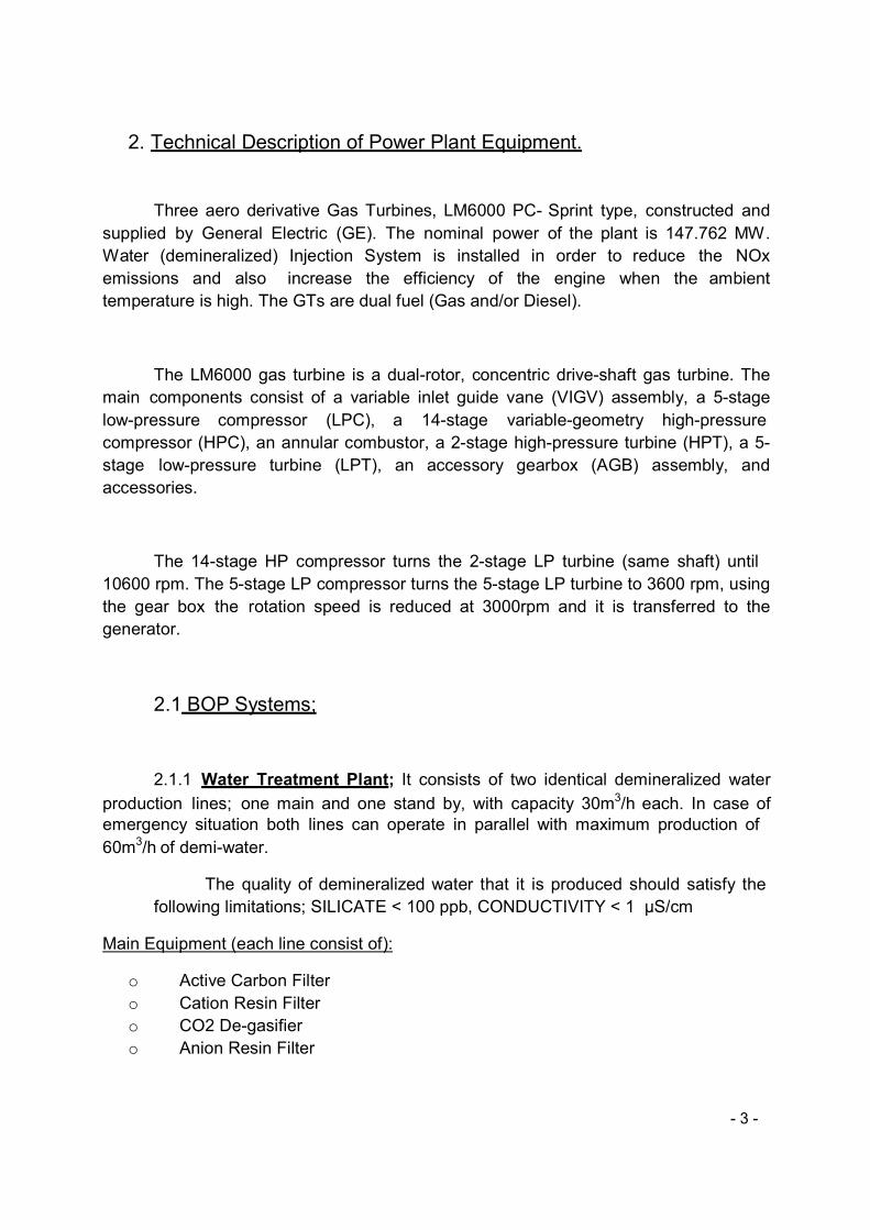
2. Technical Description of Power Plant Equipment.
Three aero derivative Gas Turbines, LM6000 PC- Sprint type, constructed and
supplied by General Electric (GE). The nominal power of the plant is 147.762 MW.
Water (demineralized) Injection System is installed in order to reduce the NOx
emissions and also increase the efficiency of the engine when the ambient
temperature is high. The GTs are dual fuel (Gas and/or Diesel).
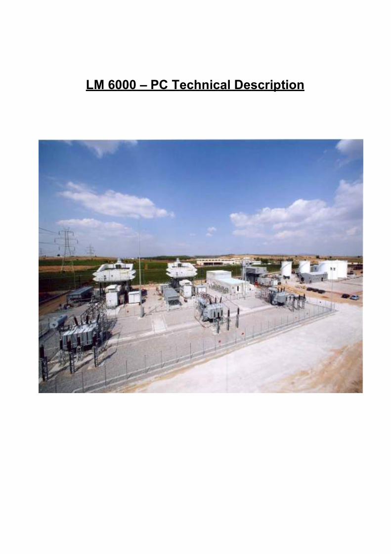
The LM6000 gas turbine is a dual-rotor, concentric drive-shaft gas turbine. The
main components consist of a variable inlet guide vane (VIGV) assembly, a 5-stage
low-pressure compressor (LPC), a 14-stage variable-geometry high-pressure
compressor (HPC), an annular combustor, a 2-stage high-pressure turbine (HPT), a 5-
stage low-pressure turbine (LPT), an accessory gearbox (AGB) assembly, and
accessories.
The 14-stage HP compressor turns the 2-stage LP turbine (same shaft) until
10600 rpm. The 5-stage LP compressor turns the 5-stage LP turbine to 3600 rpm, using
the gear box the rotation speed is reduced at 3000rpm and it is transferred to the
generator.
2.1 BOP Systems;
2.1.1 Water Treatment Plant; It consists of two identical demineralized water
production lines; one main and one stand by, with capacity 30m3/h each. In case of
emergency situation both lines can operate in parallel with maximum production of
60m3/h of demi-water.
The quality of demineralized water that it is produced should satisfy the
following limitations; SILICATE < 100 ppb, CONDUCTIVITY < 1 µS/cm
Main Equipment (each line consist of):
o Active Carbon Filter
o Cation Resin Filter
o CO2 De-gasifier
o Anion Resin Filter
- 4 -
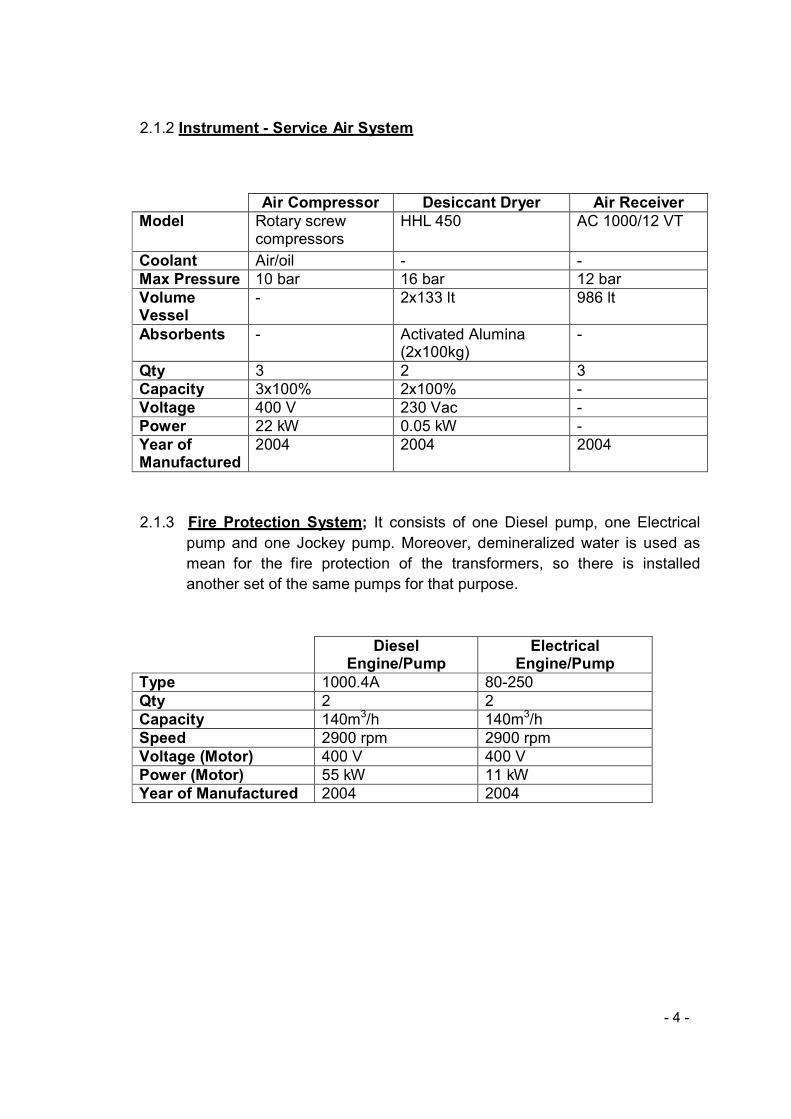
2.1.2 Instrument - Service Air System
Air Compressor Desiccant Dryer Air Receiver
Model Rotary screw compressors
HHL 450 AC 1000/12 VT
Coolant Air/oil - -
Max Pressure 10 bar 16 bar 12 bar
Volume Vessel
- 2x133 lt 986 lt
Absorbents - Activated Alumina (2x100kg)
-
Qty 3 2 3
Capacity 3x100% 2x100% -
Voltage 400 V 230 Vac -
Power 22 kW 0.05 kW -
Year of Manufactured
2004 2004 2004
2.1.3 Fire Protection System; It consists of one Diesel pump, one Electrical
pump and one Jockey pump. Moreover, demineralized water is used as
mean for the fire protection of the transformers, so there is installed
another set of the same pumps for that purpose.
Diesel Engine/Pump
Electrical Engine/Pump
Type 1000.4A 80-250
Qty 2 2
Capacity 140m3/h 140m3/h
Speed 2900 rpm 2900 rpm
Voltage (Motor) 400 V 400 V
Power (Motor) 55 kW 11 kW
Year of Manufactured 2004 2004
- 5 -
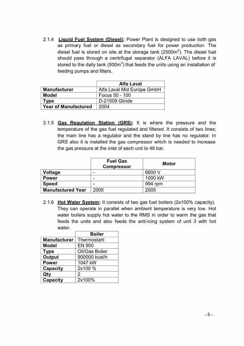
2.1.4 Liquid Fuel System (Diesel); Power Plant is designed to use both gas
as primary fuel or diesel as secondary fuel for power production. The
diesel fuel is stored on site at the storage tank (2500m3). The diesel fuel
should pass through a centrifugal separator (ALFA LAVAL) before it is
stored to the daily tank (500m3) that feeds the units using an installation of
feeding pumps and filters.
Alfa Laval
Manufacturer Alfa Laval Mid Europe GmbH
Model Focus 50 - 100
Type D-21509 Glinde
Year of Manufactured 2004
2.1.5 Gas Regulation Station (GRS); It is where the pressure and the
temperature of the gas fuel regulated and filtered. It consists of two lines;
the main line has a regulator and the stand by line has no regulator. In
GRS also it is installed the gas compressor which is needed to increase
the gas pressure at the inlet of each unit to 46 bar.
Fuel Gas Compressor
Motor
Voltage - 6600 V
Power - 1000 kW
Speed - 994 rpm
Manufactured Year 2005 2005
2.1.6 Hot Water System; It consists of two gas fuel boilers (2x100% capacity).
They can operate in parallel when ambient temperature is very low. Hot
water boilers supply hot water to the RMS in order to warm the gas that
feeds the units and also feeds the anti-icing system of unit 3 with hot
water.
Boiler
Manufacturer Thermostahl
Model EN 900
Type Oil/Gas Boiler
Output 900000 kcal/h
Power 1047 kW
Capacity 2x100 %
Qty 2
Capacity 2x100%
- 6 -
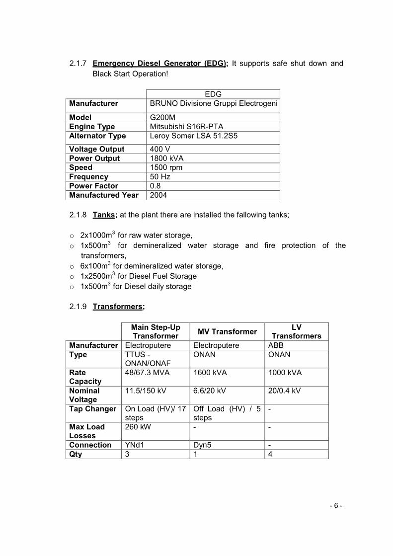
2.1.7 Emergency Diesel Generator (EDG); It supports safe shut down and
Black Start Operation!
EDG
Manufacturer BRUNO Divisione Gruppi Electrogeni
Model G200M
Engine Type Mitsubishi S16R-PTA
Alternator Type Leroy Somer LSA 51.2S5
Voltage Output 400 V
Power Output 1800 kVA
Speed 1500 rpm
Frequency 50 Hz
Power Factor 0.8
Manufactured Year 2004
2.1.8 Tanks; at the plant there are installed the fallowing tanks;
o 2x1000m3 for raw water storage,
o 1x500m3 for demineralized water storage and fire protection of the
transformers,
o 6x100m3 for demineralized water storage,
o 1x2500m3 for Diesel Fuel Storage
o 1x500m3 for Diesel daily storage
2.1.9 Transformers;
Main Step-Up Transformer
MV Transformer LV
Transformers
Manufacturer Electroputere Electroputere ABB
Type TTUS - ONAN/ONAF
ONAN ONAN
Rate Capacity
48/67.3 MVA 1600 kVA 1000 kVA
Nominal Voltage
11.5/150 kV 6.6/20 kV 20/0.4 kV
Tap Changer On Load (HV)/ 17 steps
Off Load (HV) / 5 steps
-
Max Load Losses
260 kW - -
Connection YNd1 Dyn5 -
Qty 3 1 4
- 7 -
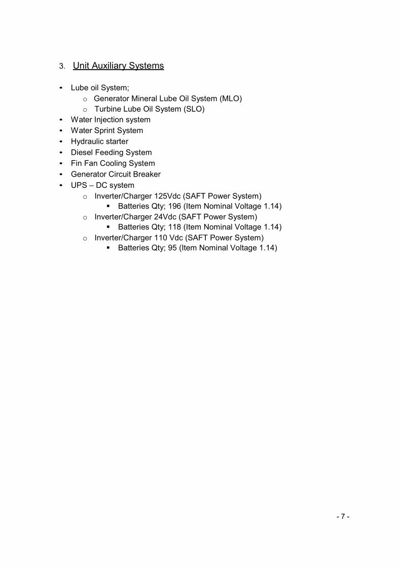
3. Unit Auxiliary Systems
• Lube oil System;
o Generator Mineral Lube Oil System (MLO)
o Turbine Lube Oil System (SLO)
• Water Injection system
• Water Sprint System
• Hydraulic starter
• Diesel Feeding System
• Fin Fan Cooling System
• Generator Circuit Breaker
• UPS – DC system
o Inverter/Charger 125Vdc (SAFT Power System)
� Batteries Qty; 196 (Item Nominal Voltage 1.14)
o Inverter/Charger 24Vdc (SAFT Power System)
� Batteries Qty; 118 (Item Nominal Voltage 1.14)
o Inverter/Charger 110 Vdc (SAFT Power System)
� Batteries Qty; 95 (Item Nominal Voltage 1.14)
- 8 -
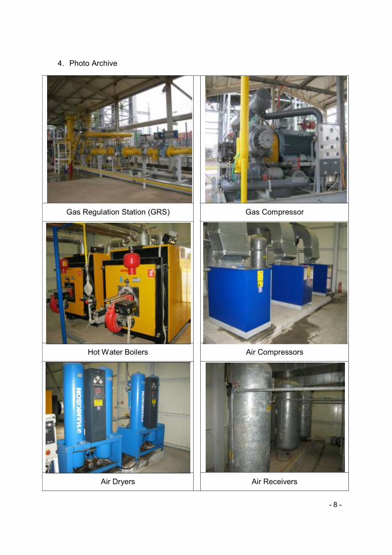
4. Photo Archive
Gas Regulation Station (GRS)
Gas Compressor
Hot Water Boilers
Air Compressors
Air Dryers
Air Receivers
- 9 -
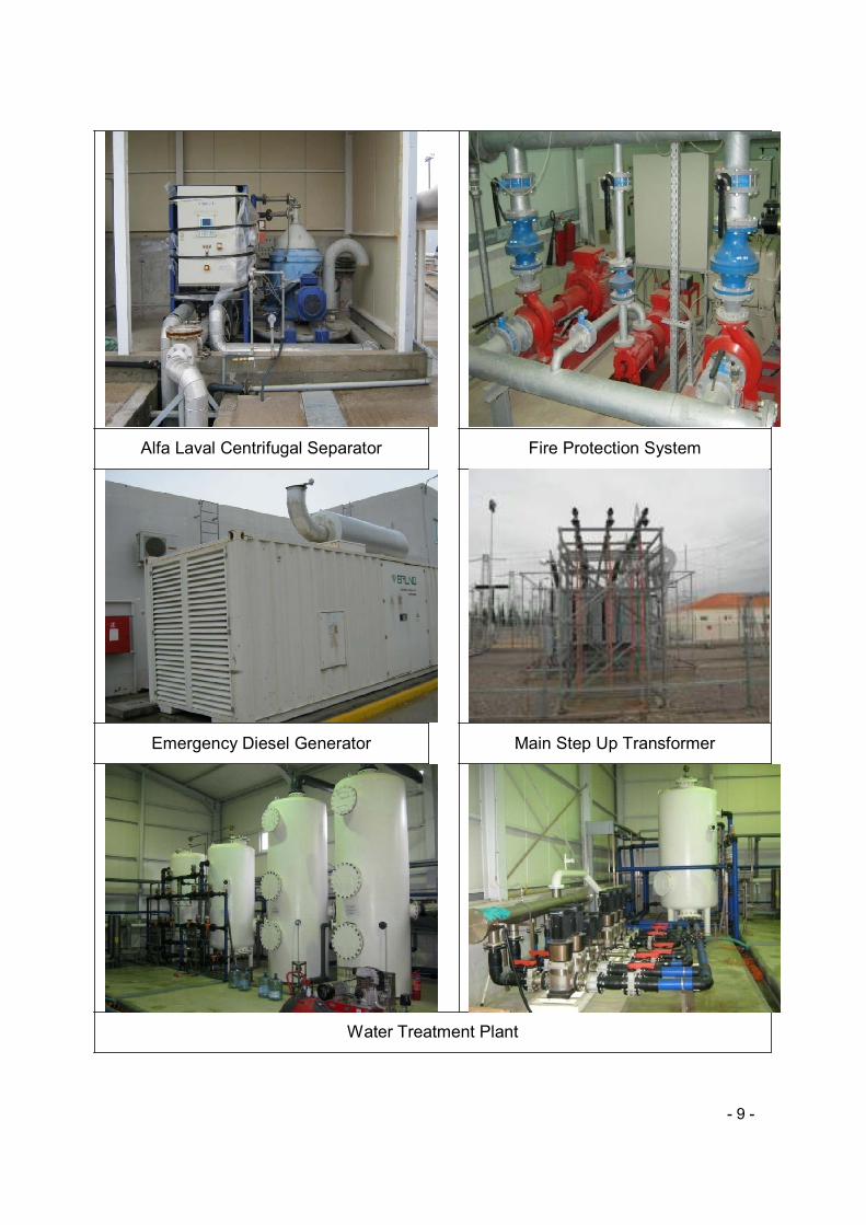
Alfa Laval Centrifugal Separator Fire Protection System
Emergency Diesel Generator Main Step Up Transformer
Water Treatment Plant
- 10 -
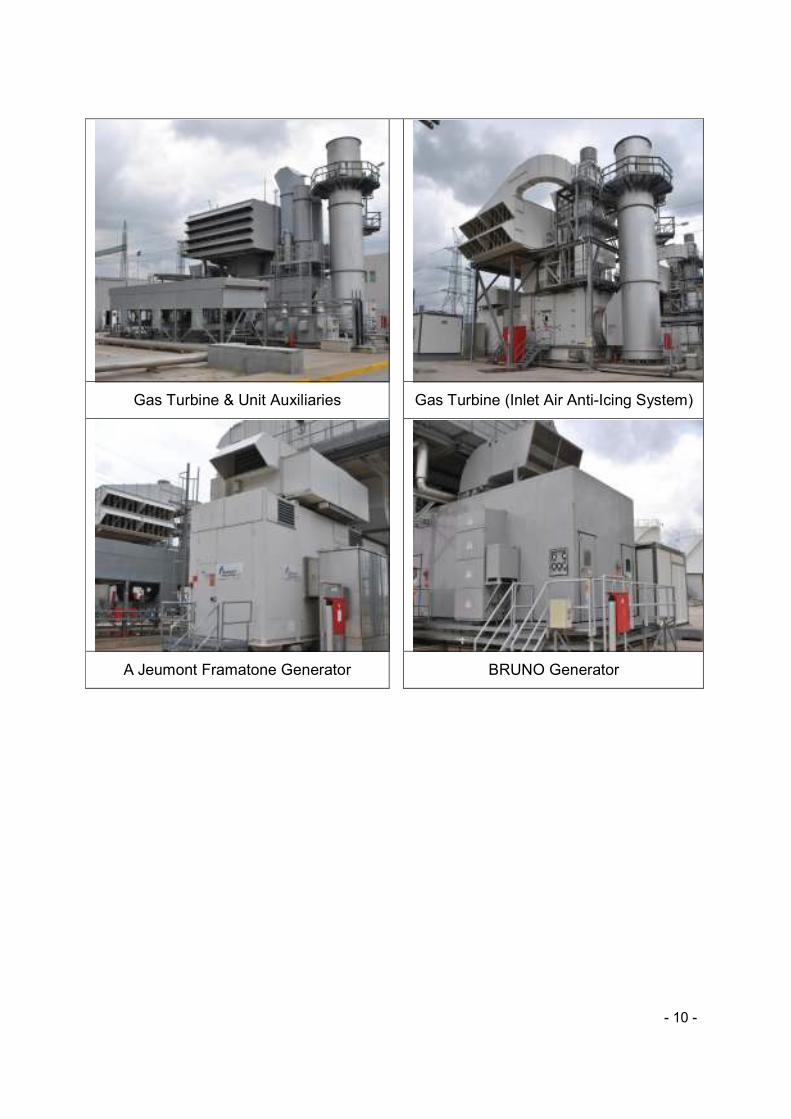
Gas Turbine & Unit Auxiliaries
Gas Turbine (Inlet Air Anti-Icing System)
A Jeumont Framatone Generator
BRUNO Generator
![TOPIC: 191006 KNOWLEDGE: K1.03 [2.2/2.3] QID: … is the approximate temperature of the lube oil exiting the heat exchanger (T. oil-out ... The current main turbine lube oil mass flow](https://img.pdfslide.us/doc/110x75/5ab48bc67f8b9a6e1c8bf965/topic-191006-knowledge-k103-2223-qid-is-the-approximate-temperature.jpg)