Embed Size (px)
Citation preview
LLNL X-BAND TEST STATION STATUS∗
R.A. Marsh† , F. Albert, G. Anderson, S.G. Anderson, E. Dayton,S.E. Fisher, D.J. Gibson, S.S. Wu, F.V. Hartemann, C.P.J. Barty
Lawrence Livermore National Laboratory, Livermore, CA 94550, USA
AbstractIn support of Compton scattering gamma-ray source ef-
forts at LLNL, a multi-bunch test station is being developed
to investigate accelerator optimization for future upgrades.
This test station will enable work to explore the science
and technology paths required to boost the current mono-
energetic gamma-ray technology to a higher effective rep-
etition rate, potentially increasing the average gamma-ray
brightness by two orders of magnitude. The test station will
consist of a 5.5 cell X-band RF photoinjector, single accel-
erator section, and beam diagnostics. Detailed design of
the test station including beam dynamics is complete, and
will be presented with modeling simulations and future up-
grade paths. The current status of the installation will also
be discussed with future commissioning plans.
INTRODUCTIONExtremely bright narrow bandwidth gamma-ray sources
are expanding the application of accelerator technology
and light sources in new directions. LLNL has a successful
history utilizing gamma-rays generated by a linac-driven,
laser-based Compton scattering gamma-ray source [1, 2, 3,
4]. Next generation advancements in linac-based x-ray and
gamma-ray production require increasing the average flux
of gamma-rays at a specific energy (that is, N/eV/sec at
the energy of interest). One way to accomplish this is to
increase the effective repetition rate by operating the RF
photoinjector in a multi-bunch mode, accelerating multiple
electron bunches per RF pulse. This multi-bunch mode will
have stringent requirements for the electron bunch proper-
ties including low emittance and energy spread, but across
multiple bunches. An X-band test station is under construc-
tion at LLNL to develop multi-bunch electron beams and
generate x-rays. This paper summarizes progress and de-
scribes the current status of the project.
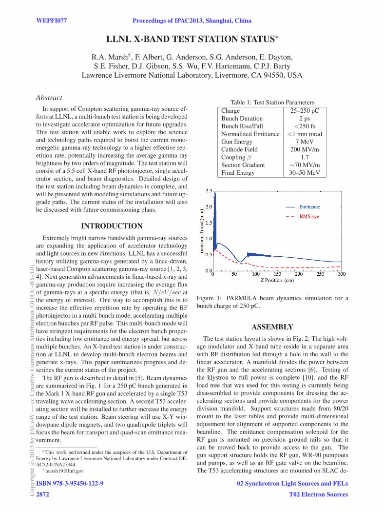
The RF gun is described in detail in [5]. Beam dynamics
are summarized in Fig. 1 for a 250 pC bunch generated in
the Mark 1 X-band RF gun and accelerated by a single T53
traveling wave accelerating section. A second T53 acceler-
ating section will be installed to further increase the energy
range of the test station. Beam steering will use X-Y win-
dowpane dipole magnets, and two quadrupole triplets will
focus the beam for transport and quad-scan emittance mea-
surement.
∗This work performed under the auspices of the U.S. Department of
Energy by Lawrence Livermore National Laboratory under Contract DE-
AC52-07NA27344† [email protected]
Table 1: Test Station Parameters
Charge 25–250 pC
Bunch Duration 2 ps
Bunch Rise/Fall <250 fs
Normalized Emittance <1 mm mrad
Gun Energy 7 MeV
Cathode Field 200 MV/m
Coupling β 1.7
Section Gradient ∼70 MV/m
Final Energy 30–50 MeV
Figure 1: PARMELA beam dynamics simulation for a
bunch charge of 250 pC.
ASSEMBLYThe test station layout is shown in Fig. 2. The high volt-
age modulator and X-band tube reside in a separate area
with RF distribution fed through a hole in the wall to the
linear accelerator. A manifold divides the power between
the RF gun and the accelerating sections [6]. Testing of
the klystron to full power is complete [10], and the RF
load tree that was used for this testing is currently being
disassembled to provide components for dressing the ac-
celerating sections and provide components for the power
division manifold. Support structures made from 80/20
mount to the laser tables and provide multi-dimensional
adjustment for alignment of supported components to the
beamline. The emittance compensation solenoid for the
RF gun is mounted on precision ground rails so that it
can be moved back to provide access to the gun. The
gun support structure holds the RF gun, WR-90 pumpouts
and pumps, as well as an RF gate valve on the beamline.
The T53 accelerating structures are mounted on SLAC de-
WEPFI077 Proceedings of IPAC2013, Shanghai, China
ISBN 978-3-95450-122-9
2872Cop
yrig
htc ○
2013
byJA
CoW
—cc
Cre
ativ
eC
omm
onsA
ttri
butio
n3.
0(C
C-B
Y-3.
0)
02 Synchrotron Light Sources and FELs
T02 Electron Sources
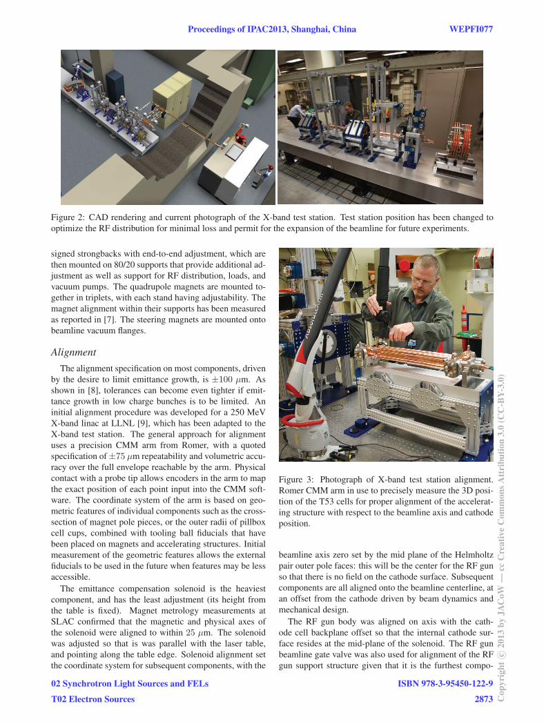
Figure 2: CAD rendering and current photograph of the X-band test station. Test station position has been changed to
optimize the RF distribution for minimal loss and permit for the expansion of the beamline for future experiments.
signed strongbacks with end-to-end adjustment, which are
then mounted on 80/20 supports that provide additional ad-
justment as well as support for RF distribution, loads, and
vacuum pumps. The quadrupole magnets are mounted to-
gether in triplets, with each stand having adjustability. The
magnet alignment within their supports has been measured
as reported in [7]. The steering magnets are mounted onto
beamline vacuum flanges.
AlignmentThe alignment specification on most components, driven
by the desire to limit emittance growth, is ±100 μm. As
shown in [8], tolerances can become even tighter if emit-
tance growth in low charge bunches is to be limited. An
initial alignment procedure was developed for a 250 MeV
X-band linac at LLNL [9], which has been adapted to the
X-band test station. The general approach for alignment
uses a precision CMM arm from Romer, with a quoted
specification of ±75 μm repeatability and volumetric accu-
racy over the full envelope reachable by the arm. Physical
contact with a probe tip allows encoders in the arm to map
the exact position of each point input into the CMM soft-
ware. The coordinate system of the arm is based on geo-
metric features of individual components such as the cross-
section of magnet pole pieces, or the outer radii of pillbox
cell cups, combined with tooling ball fiducials that have
been placed on magnets and accelerating structures. Initial
measurement of the geometric features allows the external
fiducials to be used in the future when features may be less
accessible.
The emittance compensation solenoid is the heaviest
component, and has the least adjustment (its height from
the table is fixed). Magnet metrology measurements at
SLAC confirmed that the magnetic and physical axes of
the solenoid were aligned to within 25 μm. The solenoid
was adjusted so that is was parallel with the laser table,
and pointing along the table edge. Solenoid alignment set
the coordinate system for subsequent components, with the
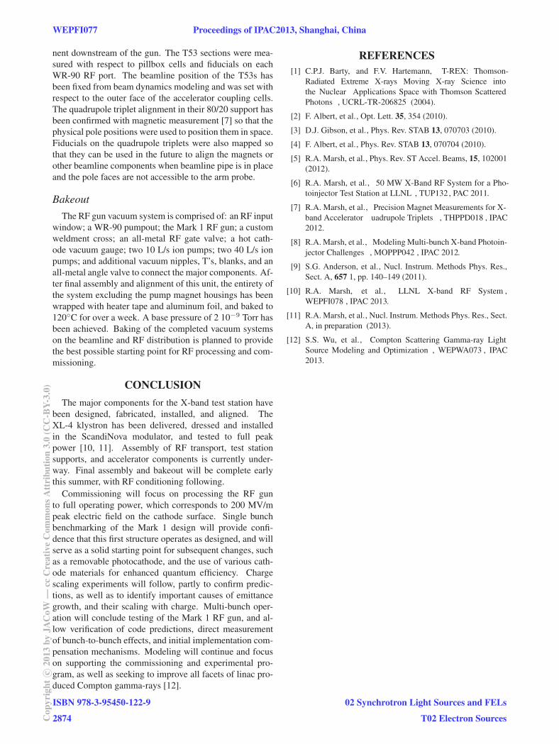
Figure 3: Photograph of X-band test station alignment.
Romer CMM arm in use to precisely measure the 3D posi-
tion of the T53 cells for proper alignment of the accelerat-
ing structure with respect to the beamline axis and cathode
position.
beamline axis zero set by the mid plane of the Helmholtz
pair outer pole faces: this will be the center for the RF gun
so that there is no field on the cathode surface. Subsequent
components are all aligned onto the beamline centerline, at
an offset from the cathode driven by beam dynamics and
mechanical design.
The RF gun body was aligned on axis with the cath-
ode cell backplane offset so that the internal cathode sur-
face resides at the mid-plane of the solenoid. The RF gun
beamline gate valve was also used for alignment of the RF
gun support structure given that it is the furthest compo-
Proceedings of IPAC2013, Shanghai, China WEPFI077
02 Synchrotron Light Sources and FELs
T02 Electron Sources
ISBN 978-3-95450-122-9
2873 Cop
yrig
htc ○
2013
byJA
CoW
—cc
Cre
ativ
eC
omm
onsA
ttri
butio
n3.
0(C
C-B
Y-3.
0)
nent downstream of the gun. The T53 sections were mea-
sured with respect to pillbox cells and fiducials on each
WR-90 RF port. The beamline position of the T53s has
been fixed from beam dynamics modeling and was set with
respect to the outer face of the accelerator coupling cells.
The quadrupole triplet alignment in their 80/20 support has
been confirmed with magnetic measurement [7] so that the
physical pole positions were used to position them in space.
Fiducials on the quadrupole triplets were also mapped so
that they can be used in the future to align the magnets or
other beamline components when beamline pipe is in place
and the pole faces are not accessible to the arm probe.
BakeoutThe RF gun vacuum system is comprised of: an RF input
window; a WR-90 pumpout; the Mark 1 RF gun; a custom
weldment cross; an all-metal RF gate valve; a hot cath-
ode vacuum gauge; two 10 L/s ion pumps; two 40 L/s ion
pumps; and additional vacuum nipples, T’s, blanks, and an
all-metal angle valve to connect the major components. Af-
ter final assembly and alignment of this unit, the entirety of
the system excluding the pump magnet housings has been
wrapped with heater tape and aluminum foil, and baked to
120◦C for over a week. A base pressure of 2 10−9 Torr has
been achieved. Baking of the completed vacuum systems
on the beamline and RF distribution is planned to provide
the best possible starting point for RF processing and com-
missioning.
CONCLUSIONThe major components for the X-band test station have
been designed, fabricated, installed, and aligned. The
XL-4 klystron has been delivered, dressed and installed
in the ScandiNova modulator, and tested to full peak
power [10, 11]. Assembly of RF transport, test station
supports, and accelerator components is currently under-
way. Final assembly and bakeout will be complete early
this summer, with RF conditioning following.
Commissioning will focus on processing the RF gun
to full operating power, which corresponds to 200 MV/m
peak electric field on the cathode surface. Single bunch
benchmarking of the Mark 1 design will provide confi-
dence that this first structure operates as designed, and will
serve as a solid starting point for subsequent changes, such
as a removable photocathode, and the use of various cath-
ode materials for enhanced quantum efficiency. Charge
scaling experiments will follow, partly to confirm predic-
tions, as well as to identify important causes of emittance
growth, and their scaling with charge. Multi-bunch oper-
ation will conclude testing of the Mark 1 RF gun, and al-
low verification of code predictions, direct measurement
of bunch-to-bunch effects, and initial implementation com-
pensation mechanisms. Modeling will continue and focus
on supporting the commissioning and experimental pro-
gram, as well as seeking to improve all facets of linac pro-
duced Compton gamma-rays [12].
REFERENCES[1] C.P.J. Barty, and F.V. Hartemann, T-REX: Thomson-
Radiated Extreme X-rays Moving X-ray Science into
the Nuclear Applications Space with Thomson Scattered
Photons , UCRL-TR-206825 (2004).
[2] F. Albert, et al., Opt. Lett. 35, 354 (2010).
[3] D.J. Gibson, et al., Phys. Rev. STAB 13, 070703 (2010).
[4] F. Albert, et al., Phys. Rev. STAB 13, 070704 (2010).
[5] R.A. Marsh, et al., Phys. Rev. ST Accel. Beams, 15, 102001
(2012).
[6] R.A. Marsh, et al., 50 MW X-Band RF System for a Pho-
toinjector Test Station at LLNL , TUP132, PAC 2011.
[7] R.A. Marsh, et al., Precision Magnet Measurements for X-
band Accelerator uadrupole Triplets , THPPD018 , IPAC
2012.
[8] R.A. Marsh, et al., Modeling Multi-bunch X-band Photoin-
jector Challenges , MOPPP042 , IPAC 2012.
[9] S.G. Anderson, et al., Nucl. Instrum. Methods Phys. Res.,
Sect. A, 657 1, pp. 140–149 (2011).
[10] R.A. Marsh, et al., LLNL X-band RF System ,
WEPFI078 , IPAC 2013.
[11] R.A. Marsh, et al., Nucl. Instrum. Methods Phys. Res., Sect.
A, in preparation (2013).
[12] S.S. Wu, et al., Compton Scattering Gamma-ray Light
Source Modeling and Optimization , WEPWA073 , IPAC
2013.
WEPFI077 Proceedings of IPAC2013, Shanghai, China
ISBN 978-3-95450-122-9
2874Cop
yrig
htc ○
2013
byJA
CoW
—cc
Cre
ativ
eC
omm
onsA
ttri
butio
n3.
0(C
C-B
Y-3.
0)
02 Synchrotron Light Sources and FELs
T02 Electron Sources