Embed Size (px)
Citation preview
L~LLU., .-
Technical Report 627
CABLE FAILURES IN THE"-AN,,/oBQS-1 SONAR SYSTEMI
"Ana,.sis of failures in the depression/elevationdrive-motor power cable and recommendations
for their prevention
TL Lewis
June 1980
SnMid I1\(pWr fo1u [', 'Ud SLptelbl,-r 1979 - Febriatry 1980 jPrepared for
,'j , .' - Naval Sea Systems CGrnmm and
I j (, ;. j ,. " , Code 63X143LL-i "u"
p/,II ,(',d l,. ,,II It ,I ; , d ',tor t, ..1vr UrdifllH t(.
NAVAL OCEAN SYSI EMS CENTERSAN DIEGO, CALIFORNIA 92152
3 0 ")9 ! ,
j
NAVAL OCEAN SYSTEMS CENTrr(. ;AN DIE~GOCA 92IS2
A N ACT IV IT Y 0OF T HE N A VAL M A T ER IAL COUM MAN D
SL GIJILLE, CAPT, USN HL BLOOICom'mander 7 IMMI gc IiFii T UF)r~
AL)XI 1. - S] RAlIVI: INIORMA] iON
W\ork wa,, perl'ormfcd byý iiiciinbcj' ol ticlkL I()pmcIOljlt IB jimIic NOS( ( iidc ý'31
f'or thc \av~i1 SCýi Systcjini('otilindi~, (oc' (.3XI43. 'I lie aut hrthanks !llimlk If,li Ild.i" -i'i'of the Naval Weapons Support Center and' Tow Yee ot'thc Marc Island Naval SlflpyariI
for their cooperation in this unalysis.I
RA kiclxmiii. flc~lfI Hl d LL.lf'itSoEiaI Sy'"tcnis NWc::Ipm ( uuJ11jol '11d 'suri.bivi.)joI
I S I AS ,I t li 11
A
1i
.1!1;'1t
Itkf I Al F % Ill f' 111101
r - T .-j -~- a
- i-f
JL .111. jI f r
* ist~h. tlt' vollfl-l At l -val.v I i&& iII -, (5 l-il-.- . ., 1 .T i< j T
IA.g I Ay V4itA';Z
-f1.1 pi P otU l i F ' i I ~ ' 0' taf h
"Yl~ uia k il 1 i. Al ;f4tI ll h tW A IvI
4.11 .5 fl~
I~It
1-111 I1 W i jti- I t to y Itui 'l #1 th o F #.I s lil t o wUm U' 4 1 Ila * ' ~ - ~ ~ - =
* ii , ,.Alij _.nj I 't"'"'ue Fiii Vle it 'I BIa em! a t fit,
P1i111" ti Ij i I!. mlt ,l 'I v t Ii t t o ' b d d ttt l. A4i t '
er ll -I it' l -I It I 111C llI t 11 11 I lli IIA') 4 l f f ~ l i 111 11 i
j it ij1 .40 1 1 4 t i ult A
*j.if. U t i14. Aiflhi &il 111 F t41 Ofs I'3 'f''
I S( I ASSII 11 1)____
S-iiV CL AItIrICATIr.J UP I I!II$ PIP UPV ;who, !jIa F,a.vsfe,
IF' UP11II Y -LL I 61 11 A IloN if Till$ U*A(,[ W,, ,I 4!,4.PpI)
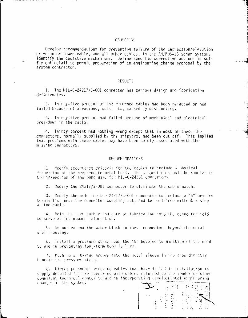
OBJECTIVE
Develop recoitinendations for preventing fail ure of the depression/elevationdrive-motor power-cable, and all other caibles, in the AN/BLQS-15 Sonar System.Identify the causative mechanisms. Define specific corrective actions in suf-ficient detail to permit preparation of an engineering change proposal by thesystem contractor.
RESULTS
1. The MIL-C-24217/3-.0O01 connector has serious design and fabrirationrdeficiencies.
2. Thirty-five percent of the retLurned cables had been rejected or hadfailed because of abrasions, cuts, etc, caused by mishandling.
3. Thirty-five percent had failed because of mechanical and electricalbreakdown in the cable.
4. Thirty percent had nothing wrong except that in most of these theconnectors, nonnally supplied by the shipyard, had been cut off. This impliedthat problems with these cablus may have been solely associated with themissing coetaecLors.
RECOMMLNDAT IONS
1. Modify acceptance criterii for the cables to includre a physicalse~tioll of the neoprene-tao-wetl bond. lhe inspection should be similar to
the inspection of the bond used for MIL-C-24231 connectors.
2. Modify the 24217/3-001 connector to el iHinilate the cable notch.
3. Modify theý mold ioio the 24?1,/3-001 connector to include a 45° bev(el dterlrination nelr the connector coupling niut, and to I)e fadired withouL a stepat the cdble.
4. Mold the part number mind date of fabrication into the connector moldto serve as lot number inuonnation.
5. lo riot extend the water block in these connectors beyond the metalshell hous i lg.
6. 1rlstl 1 a prussure strap near the 45° bevel ed ter, iination oi the ruol dto aid ill preventirno 1orlg-terin bond iailure.
I. M•chi llo a1 ) 0-rirli groovei iuto the metal sleevu in the area directlybeneath the pressure strap.
6). Jirect 1ersonr 2el r'(lov irig cables that ha]e failed in install at t ol 10s ul lly dut, i I ed I a ii I ure see u nr ios w I t h ca bl us ret u rned to the vendor or, othercaugJni1 7 ,1W. t(,01r1c cl C eI nter to a ic i l i incor-per'at i g 'v ulc l opilrl(t.aI enigi ileUri rgchdanges 1in the sy, -.m. "- ....... -
L i -(•r.
fil
9. Direct: personnel to avoid rough handling of the cables.
10. Fabricate the coupling nut from material that would eliminate galvanicreactions within the connector. This material should be 316 stainless steel.Teflon tape should be used on installation to prevent thread galling.
-I_
CONTENTS
BACKGROUND . . , page 4
DESCRIPTION OF TEST CABLES . 4
CONDUCT OF ANALYSIS . . . 11
Objectives 11
Investigation Method . . .
TEST RESULTS . . . 15
Depression/Elevation Power Cable 15
POSSIBLE CAUSE OF BOND FAILURE . . . 41
CONCLUSIONS AND RECOMMENDED SOLUTIONS . . . 41
APPENDIX A: CABLE BONDING, FAILURE . . . 47
APPLNDIX B: AN/BQS-15 CABLE FAILURE ANALYSIS MLLTINGRE PORT . . . 63
3I
BACKGROUND
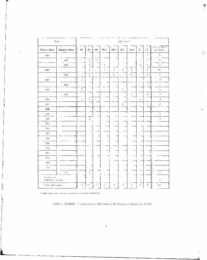
The AN/BQS-1 5 sonor syst~em has experienced an i nerd inate amount of oul -board cabl e fa ilure s, partciCii cr1 *yWith I th de pre ssi on/ el evatit1on (P /1)drive-motor power cable W31 (part 8-600113652). Other AN/BOS-iS Outboardcables also have been failing at a very high rate. Failure of the P/F cable,-ccau11sed by waet r fl ood ing of theý P, ,conlector , dlamagegs the D/ I r ivye mot or.TWs ser i OiSl1y degrad as the SUhP01iner ios forw~ird- 1 oo capa bility , req i rk Srmajor repair, rind results in high repa)ir costs. Table I 1 isi~s the cahles thathave been sent to the fleect as repl acement i tems.
NAVSEASYSCOM 63X143 requested that the cable failutre riechani sins he idolnt i -fled and specific corrective action defineod. Recommendations were requlestedthat Woul1d be suff icieantl1y dota iied to perit it proepa ration of anl enlgi neerl .ingchange proposal by the AN/FIQS-15 contractor, Aiietek, Inc , Strazi Di vision.,
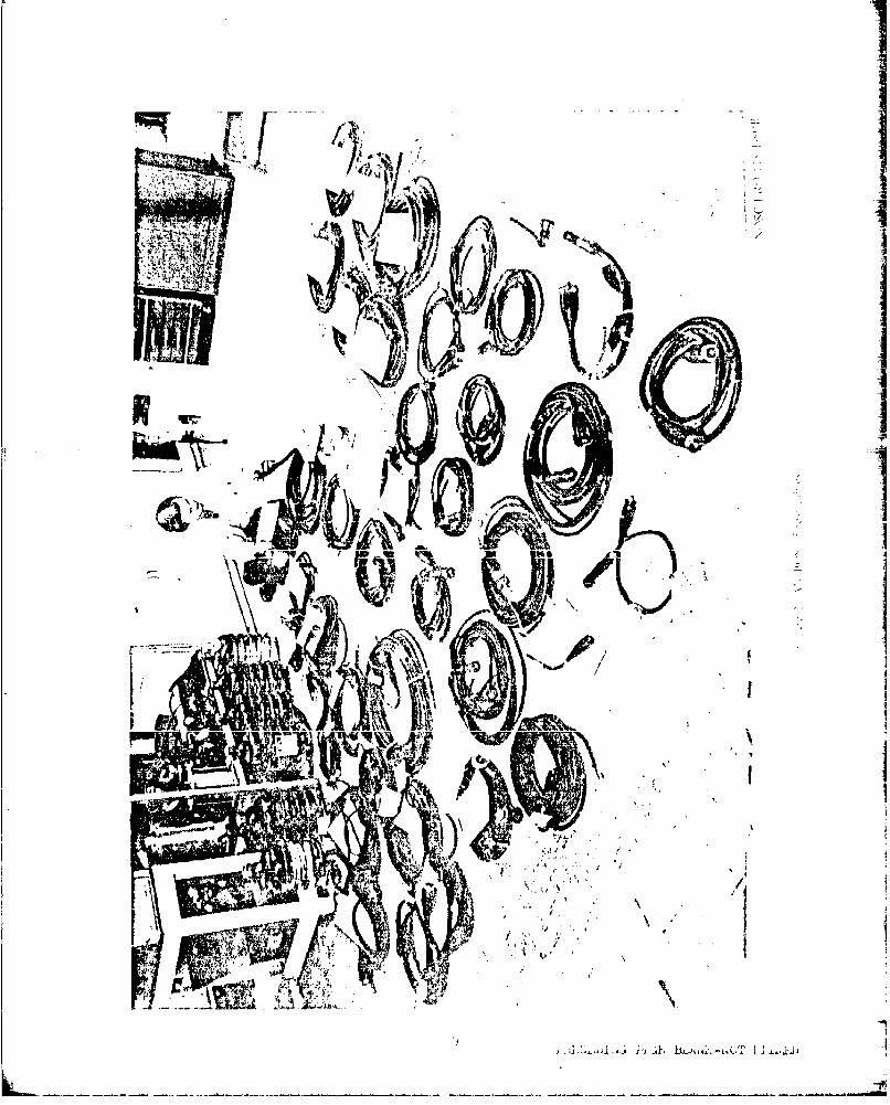
DESCRIPTION (IF TEST CABLES
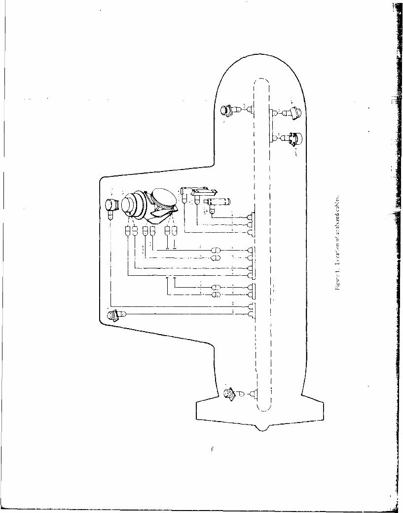
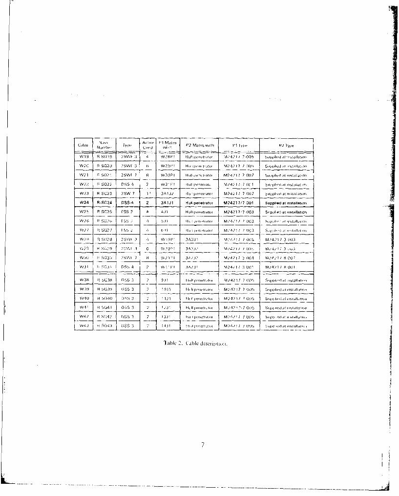
The location in the submarin noif the cables examii ned in thi s anal,1 ysis isshown in figure 1, and their description in table 2. There were 19 different -
cable numbers; the total analyzed was 41.
Table 1 liist, 47 cahl es as reploced, hut not all of the tailed car~l s' wo)rrŽreturned to0 hinetek, or Gsc . All1 of the cabl es ulsed inl this anialysi-s had beenlret urned lto thet ek as defect ivye, exc epl one , a 5(1(ser 15M124 ), V'Jhich wiasreceived from the Anecom Pi visi on of littori I ndust~rieas. I Vs hi story isunknown ; /'jiecom has rio kiiowl edoe of the aie
As canl be seean inl table 2,all of the caNas, su1pil ied t~o NSv b f4-retekh ave M IL-C -2421] coonec tars on at. 1east eone owl . 1 he correctoers h a no I reinto 14 pins . Two o1 the cables use, 90' connectors ; one al these h,]' 3 pills ill(,,the other has 14. The hi tter ends of the cahl as have a MIL-1-43 ort siru ýhconnector, installed at the shipyard. Sourie ci the carnlas returnedo to Anetl~ohad these connectors attached, however, i'ost haid been remIoved. I igujrt' " how"the ahov e c ables. Note thait. at least thtree HoveC onl y pig to erid m.
4
EIect,,ic Boat Newport News 40 4G 48 49 -1 49-2 bO1 50-2 1 . ' 1 -'It,
-1 "A'1
7 901 1 3 1 3 1 10
691 1111?
694 21
G~b1 - 1 2
I3
60 / 1 i
698
001t) 1
700 2 3
701 i7(yI --
II Om
70:1 ______ .... _
71) I
" liyt C Jl ", tIyiI;, s Id4 "1 I It h.o 41
"{,fl' I ahle Id Alnb ',,/ HQ' J I t,,', I'• ld' by. (1 h(,L)jlk~ 11)7Q)
1111'1. A.,N/iL,)S1 I I(i~LIlCI'ILlII ,L.1hI1 scui In the liedl (Is, Il IJu'cejinbciJl 7,t).
II
I
II
Numb I ~ iv Pt Mil P2 Mzito5 with P1 Iyoin P2 Ilye1
4M 19 RI SO 19 2SI'l- 3 4 1,42 8 P I IloU wi ,,o f"12421 7 "100 5 Sipll .fi ,i fI I3ic'
W20 B S020I 2SWF 3 6 W?9PI HiiI pecit,,tw M24?2 1 7 001., Supi,HiI,,i 8 ,itjil, O
WV21 R SW. I I2siA/ 7 8 W30PI 1 hll p,weiorao, trv?41241 7 2 00 7 hetI~lidII i~t ,nMltliI d
W.'2 F? S022 DNS 4 2 '53 1 PI li/I Pilnelii. M.)'42 1 7 (IC 1 siii,phleili idtiii
'.523 R S 2.3 2 SW 7 1 1 J AW Huil Imnetftor M 242 17 7 00W SiiI,phriw at lmiall itioi
W.24 R-S024 DSS-4 2 3AlJ1 Huillpenetrator M24217/7-001 Supplied atnstallatiori
W2S 11 SO?5 FSS 2 4 4.11 Huhl ~ileriirtiauo M24217/7 003 Si-pplied at installationt
Vv71 B 6 3? 88 7:L I' 8,j I 1011iIiii M..4212 1 003 8., phi iij
V' 57 11, SO'/ I I5 t 4 6li p( i"tiioi M.'42~ 1 7 7 00 3 S 1 IiiW28 P, (I)i B 8.\ 3 1 W1111 3427; 1 __:' 4, 4 0t U2 0
v3:0 HI SQ0( ?S521 7 8 Vi21FI 3 A,,I M,' 4 21 7 3 004 M81 / 8 007
VW31 li S1103I [SS 4 2 .1 1 t1 3 A2.' 1 M14)lI] 3 0(11 M24? I) H1 001
01838 It 8038 088 3 2 9jil Flll puiiirtriti M242 1 7-0 S upp1,'-I i't liIM6i1l 'ii
W:39 B 809 ss 3 2 11)11 1-10, P",~ti M2421 17 7 ooll suppiiiuild ,n.I'ml ltifuri
VV4(1 it S040 088 3 2 1 231 ll,,I pil,ti, M24,11 77 01185 S(p'.liiiIi ribi alihii
VV 4;2 It S0412 IWi. 3 13 lb HU 1 0iiio M1247117 7 001.7-1 tu~i tibl~
L 4 Iv4 1, i(4 1353j!~I Mti ' 1M4) 17 I 0717, [ýliiIwhit it ,~fI~l
Air,-
IN Ilk
CONDUCT OF ANALYSIS
OBJECTIVES
The princi pal objective of this analysis has been to detervii rio the 1110,11of failure of theo W31 cable. Additionally, the modes of failure of all othercables were recquired to be determined.
The specific objectives hove been to determiine CauIses arnd 'QxtUn"t 01 iJblefailure due to
Flexing of the cable, including the effects of currently usi-d rslatotechniques, eg, bundl ing of several pedestal cablus, (xeiy AbLebending
Poor adhesion between the connector miol ding dind tue cahbl e in rcl idhIig powcable mianufacturi ng techniques, eg, improperly cleanied molds,,, ,ec olmold release, chemical incomipatibilities
Poor adhesion of neoprene and epoxy to the connector; analysis of thispotenitial fail ure mechani sm cons "Idered iranufacturing lechiniqin:.,proc ed ures , iand qUoalI ty a ss u r drce ini a dd it ion to chcrii i itl,i nc oipa t ibil1 i t ies
Molding imperfections, such as b[.bbi us, ini the ifOreCaid Lprixy
Faillure of cabl e-osse~ribly comipone~nts such as, f)iec'r Y iwj
Storage and aginrg
INVESTIGATIuN MLTHOD
In~iti ally, 40 idiled cable-, were deli vured to !PS.All vwtr r ifindi cat ing part, cable, anid serial rrulirbers . seria nulriburiie wil ( tciip'dc
the brass' cwipl ino nut of thu- T411-t.2421 / crnriectur-. 1hii: arrily,,i Scr_
1. Ldch cablic was physically i nispected ard Theeu l viotu. e rccid!ud
?. al entcharaicteristics of cable lfiirisW! .ýltg pa t l
a close-up 1 errs
3. Cni-iiino ity tusts were wade Lu deteriii i e
he~ stnceOf each linle
Short cirecuits bet-weei 1 iwrus
4. Ar insulcat ioni rusi stanice test. ( " i OO V (k rdarigniiee a
mai~de on each cable
5. Cables wore. X-rayVed to det enrine
ConsLruct i101 deta i IS
Bondinq breakdowns
uther internal characteristics
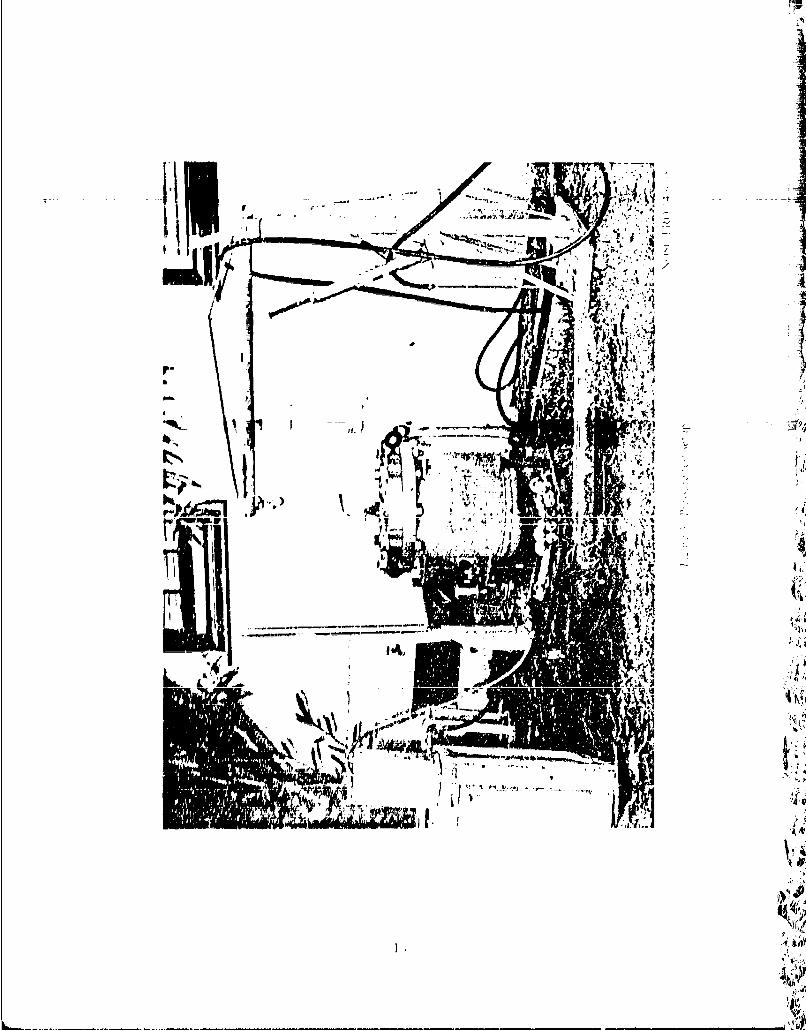
6. A test fixture was fabricated to determine the vol ume of the ccab'ethat had previously been flooded by water; figure 3 illustrates the test se5lOIpin which the cable was placed into a water-filled pressure vessel and pressureincreased until the water (laced with a red dye, a barium sulfate solution,and a wetting solution) was just visible in the exposed connector
7. After removal from the test chamber, the cables were X-rayed anddissected to determine flood-failure paths, and were photographed usinq ac~lose-up lens; they were also photographed under ultraviolet light
8. Those cables showing no visible signs of leakage after at least 30minutes under 1000 psi (6.J95 MPa) were again tested for insulation brekdowtiusing 500 V dc and a megohmeter
9. Paul Henderson of NWSC Crane examined the neoprene molded material forimpoper curing, effects of aging, and other reasons for loss of bond to thesteel casing (his report is in appendix A)
10. Installation procedures were reviewed and shipyard installation
techniques were monitored to determine possible areas for improvement
11. Failures caused by handling were identified
12. A meeting to review test results and their interpretation was held itNOSC on 5 February 1980; those in attendance were from NAVSEACENPAC, Ametek/Straza, NWSC, NUSC, Mare Island Naval Shipyard, NAVSECNORDIV, and NOSC (areport on this meeting is in appendix B)
12
. J4
P-Nt~a-7INil1
TEST RESULTS
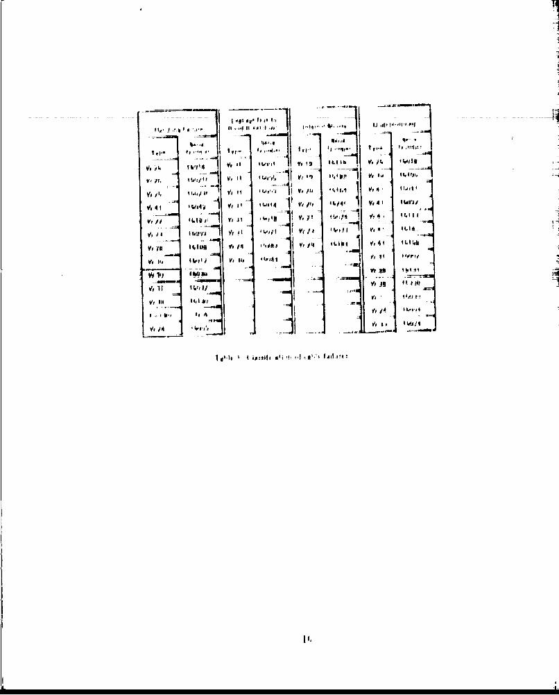
Table 3 lists all analyzed cables by serial numiber arid type, anid ci a',s -fies the mode of failure. Failures due to handling comoprise the larglesi. groujpand are caused primarily by abrasions and cuts in the cable, not by normaliwear as installed.
The next largest fail ure group consi sts of cables where causes coul d niol.be determined because
Failure cause had not been documented]
Failure occurred in a connector which had been cut. off and not. suppliedfor analysis
Failure is intermittent and cause could not be determined dur'irn arnoly'J.b
The group listing leakage due to bonding breakdown showc, a pred~m~iriuice (ifFthe W31 cable, the pri nci pal test speci men in this i nvelt i yat iuo. (lily tho:
<W31 cable showed visual signs of leakage at the pin interface. during prelldirt.testing. The W30 cable showed bond breakdown or leakage innide the connectorof one specimen. This was t~he MTI.-C-?4217/3-004 (P2 on W30). A W24 cab1'e,which had been involved in a coll1is ion with ice, anld, therefo(re , Win I~e:'14d IIIIthe water-pressure test, showed flooding and a strongU ledakage paith irit'j 0t_.pin area.
ihe internal shorts ljr-oup i ~ olw ~zwr' r i' i ~n~duning the physical and electrical i uspctions.1 Al~proxifinately hill of 11.111group wads didacnosed after lpressure_ testing the cWb I~.r~'y a ipo
water penetration wore. ohserved inr the se c a hi , ý we , Y - oy iiIJ*c1.showed that the shi el ded areas were too clo us to(Jel~ier . 11 appar l.~ 11oth rg a al d r igoi.iad i ftecb : rIo e apressure had caused the li nes to touch arld tha3t. thi(t wit" par lly tlf're, r 101t
pres sure on the shields had opiened the croriltoc a rid ho a'l a1 owed Ohw a i spas,, the electrical inuspecti on.
UEIPRLSSIUN/-LLEVATION. POWLR CABLI
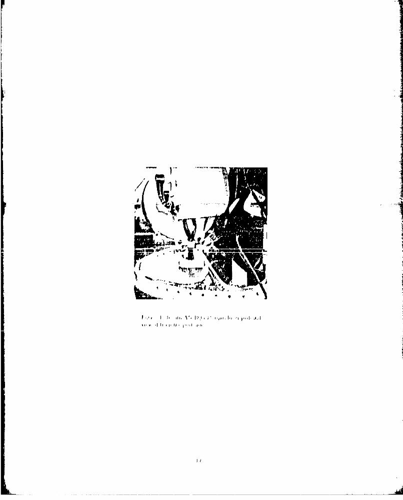
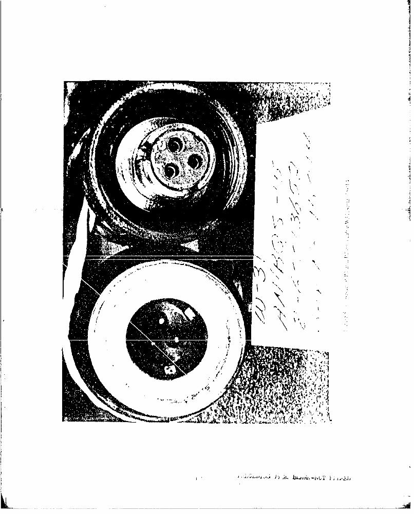
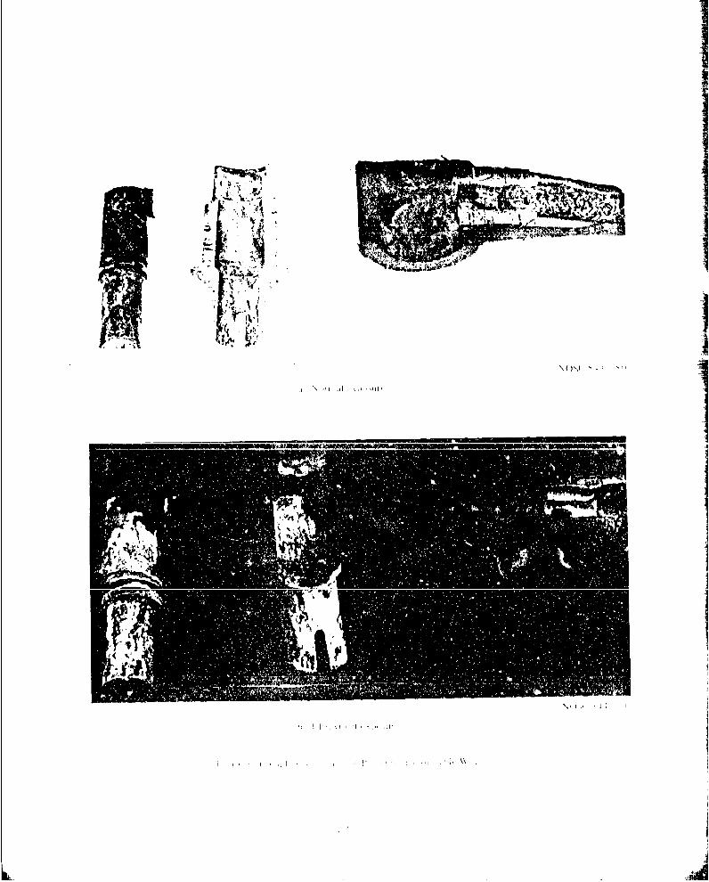
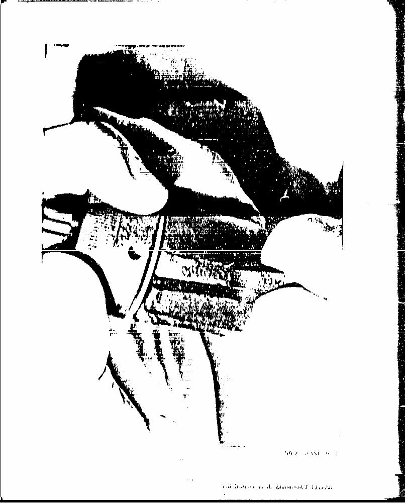
I iguru I thiows' the in situ i rstoll 1 t ion Uf Oili W31 'jiid W j cils l IhII(AN/BQS-lb pedestal . Failore, Of trio sril[Ire-y 90"j conneto(Ar (101. Odide(of ti'ýmotor) precipi tated this ano lyti s. The, -nts. ld ,ijr Y OiioiirI W'I ;)(" ar i md Oihefree, motion of the pedestal asseniibly w~ouild allow Ilodi icd'. ott' to 1)(,11 (iofthe~se coninector's viithout si gri f i (util. Coni. rdji tit 10 ii .'e I /( il" h~',(inecltors H1 anid P? of the W3l cabl (se 11)(14) . ý pot L1Ui';c.onol Of h"90' port~ion of the P? conniector is showin in ii gut e 6; th'- piO uk r ( rot viaIlywhi to,) at the center of the f igure i ae dye. etarIrAl. IiJIg to, this ' ul, lthe connector. ihere is little, il (illy, bonld uveý ai V-t y lirge O an a o'.s111doreajsons for bonid Tail ore in this, connect-(or ore d ui 1 ,dill r'd
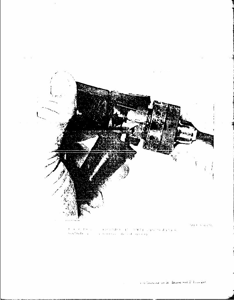
I i g ire 7 showsr ani en 1 a ege-uirit of tlle I ]Ii' oii tI iI i L I hlack Of surf ace preldrit ion for bond i rig. L rlan to lobe' 011 tho .'et Iswerle cdausd b~y the di sseo i rig tool . A\ cioiiil ec U tei. '-IoFI of Lb s Lypl' of
i -I,
JL~q tet
V, 71.~1 y, ato fit;
Uv,'. V. IN
Y, I. V, 'ten/ V
is, It W' 1 i/
two 1
M,1
Voi In
Ve 1eA 4 IrfI ( i l i I t
I ' js~ k I ,,
gldt~~~ ~~ I '.llolfili'
IIII
I
F i.7
�ii� 9, I*1
mj-�-T T�4a 4
I I I9 I
I i
IIIi
I
4
V
B')
A t'.,tjJi ,t.,, � .b±44 1t,, bC'& I .� tJL.IJ
II
t
4,.
0�4
I Ii' i r
?1C ll Mi.11 hi
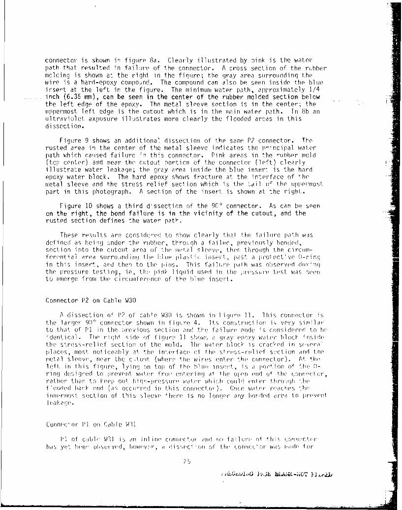
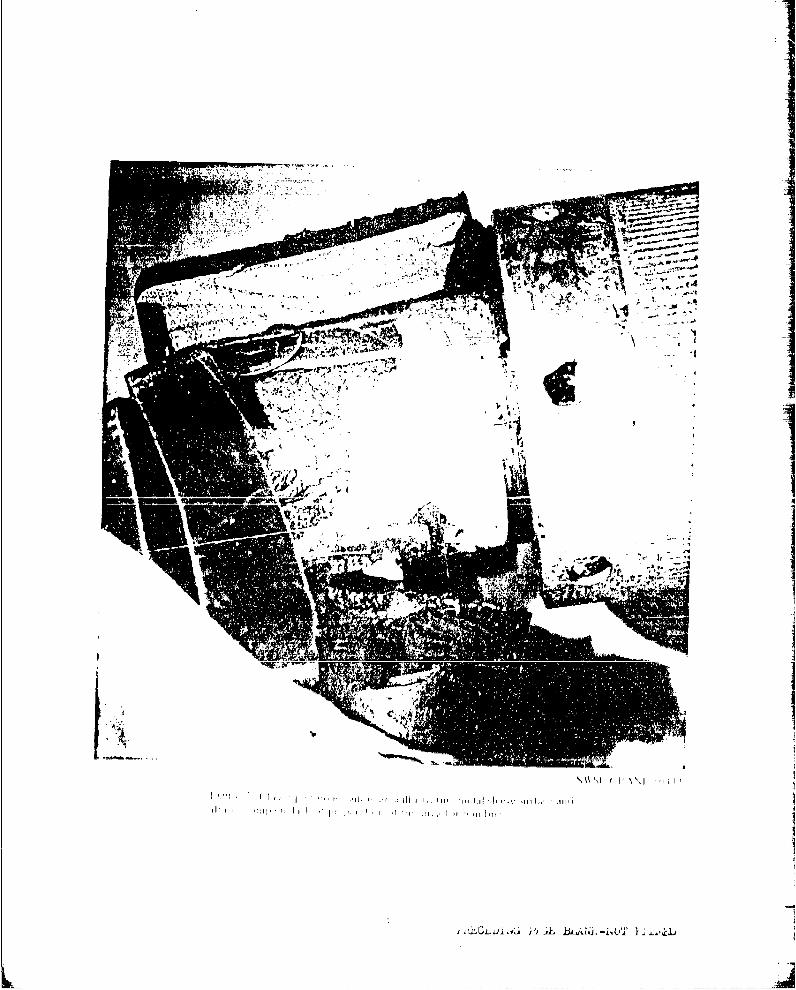
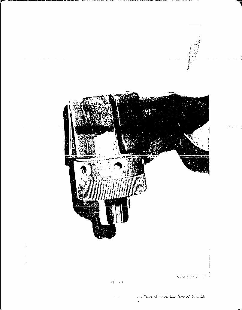
connector is shown in figure 8a. Clearly illustrated by pink is the waterpath that resulted in failure of the connector. A cross section of the rubbermolding is shown at the right in the fiqtire; the gray area surrounding thewire is a hard-epoxy compound. The compound can also be seen inside the bltieinsert at the left in the figure. The minimum water path, approximately 1/4inch (6.35 mm), can be seen in the center of the rubber molded section belowthe left edge of the epoxy. The metal sleeve section is in the center; theuppermost left edge is the cutout which is in the main water path. In 8b anultraviolet exposure illustrates more clearly the flooded areas in thisdissection.
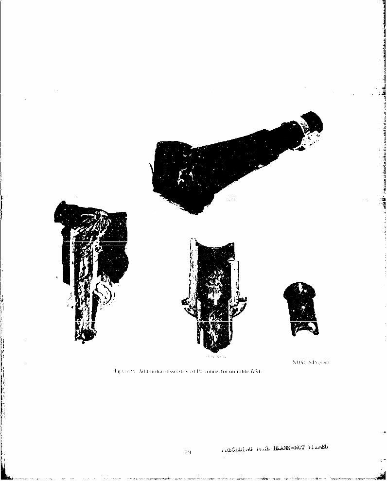
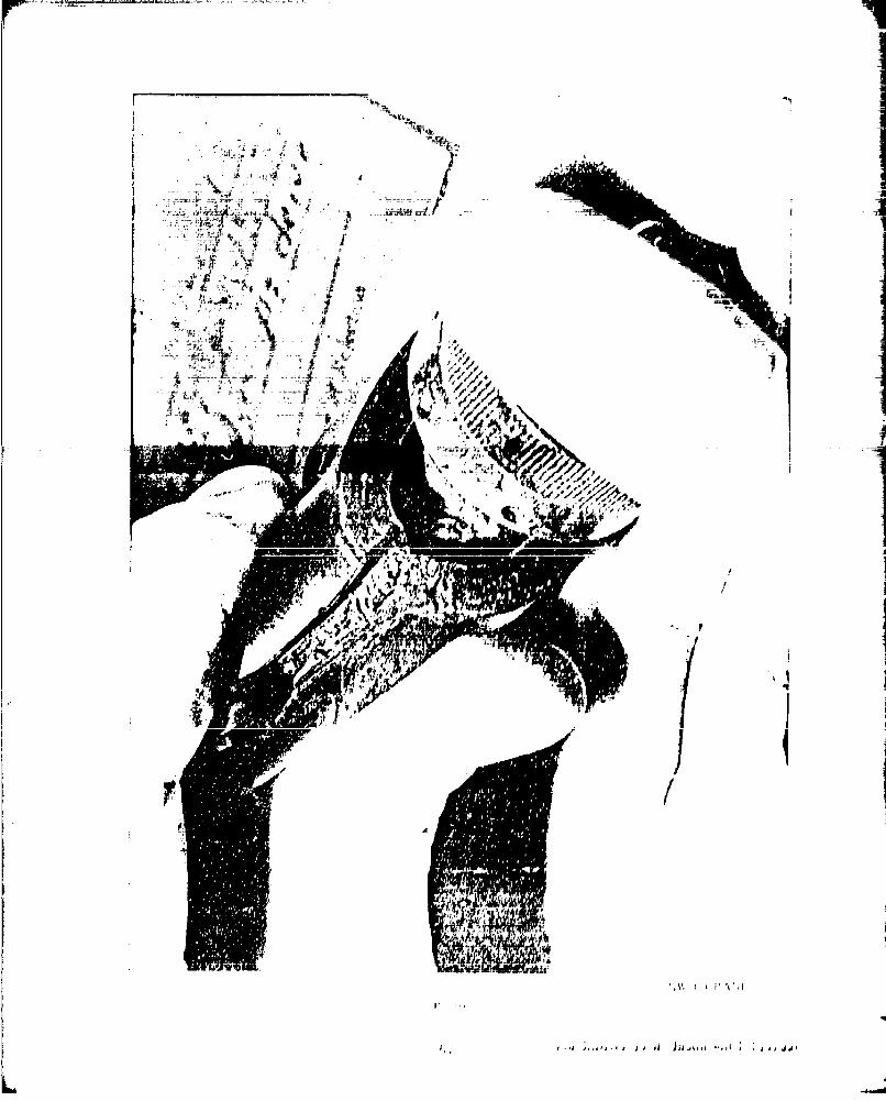
Figure 9 shows an additional dissection of the same P2 connector. Therusted area in the center of the metal sleeve indicates the principal waterpath which caused failure in this connector. Pink areas in the rubber mold(top center) and near the cutout portion of the connector (left) clearlyillustrate water leakage; the gray area inside the blue insert is the hardepoxy water block. The hard epoxy shows fracture at the interface of themetal sleeve and the stress relief section which is the tail of the uppermostpart in this photograph. A section of the insert is shown at the right.
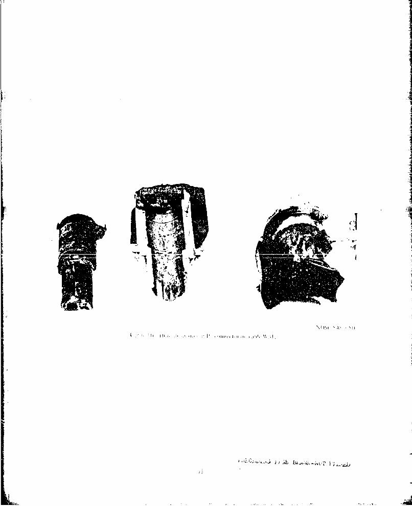
Figure 10 shows a third dissection of the 9n0 connector. As can be seenon the right, the bond failure is in the vicinity of the cutout, and therusted section defines the water path.
These results are considered to show clearly thal the failure path wasdefined as being under the rubber, through a failed, previously bonded,section into the cutout area of the metal sleeve, then through the circuim-ferentiat area surroundridI li. e tiI ltidh.eL Ii,.', Hpas,, a Iot.cti•ye h-riop,in this insert, and then to the Hoins. This failtire palh was observed d(jriinuthe pressure testing, ie, the pink liquid used in the pressure test was seento emerge front the circumferience of the hblue insert.
Connector P2 on Cable W30
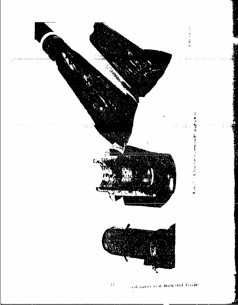
A dissection of P2 of cable W3D is shown in fiigur 11. This connector isthe larger 90' connector shown in figure 4. Its construction is very sii,,mlarto that of PI in the previous section and the failutre mode is considoerd to heidentI cal. The, r iph ide of fig re ]1 slows a gray feipxy wal(er block ins ide
the stress-relief section of the mold. lh( water block is cracked in s(,veralplaces, mosi noticeaily at the interface of the stress -relief section (ind thetetal sleeve, near the clutout (where the vi res onter the connector). At theleft in this figuire, lying on top of the hltue insert, is a Iportion ol thme ')-
ring des ignfed to prevrnt wde.(,r frot enttering al. the open end (0 the connoct or,rather than to keep out, hiqgh-pressure, waler whic h could enter throiugh theflooded hack end (as occurred in this connector). (irloe wter reaches the,innermos t section of this sl eev(e Ithere is no lonroer any horiled orea to preýventl eakage.
Counector P'1 ont (able W31
P! of cable, W3] is arn int in( confrer:tor arid rno lailir-e 'A this co rnn:terha1s yet been observefd, however, a dissection of thlu conrlc'or was made Ior
25 1
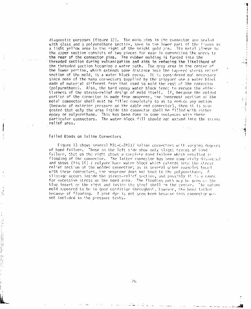
diagnostic purposes (figure 12). The main pins in the connector are sealdwith glass and a polyurethane section, seen in trie lower part of the fir 'ure asa light yellow area to the right of the bright gol)d pin. The metal s>levw inthe upper section consists of two pieces for ease in connecting the wires tothe rear of the connector pins. The rubber molding is forced into thethreaded section during vulcanization and aids in reducing the likelihood ofthe threaded section becoming a water path. The gray area in the cenl.er ofthe lower portion, which extends some distance into the tapered stress reliefsection of the mold, is a water block epoxy. It is considered not nezessarysince none of the many connectors supplied by the shipyard use a water bloctmade of material different from that used to mold the rest of the connector(polyurethaneý). Also, the hard epoxy water block tends;- to reduce the effer-tiveness of the stress-relief design of mold itself. If, because the moldedportion of the connector is made from neoprene, the innermost portion oF themetal connector shell must he filled completely so as to redice any motion(because of exterior pressure on the cable end connector), then it is sw,-gested that only the area inside the connector shell he filled with eitherepoxy or polyurethane. This has been done in some instances with theseparticular connectors. The water block fill should not extend into the stressrelief area.
Failed Bonds on Inline Connectors
F i gure 13 shows several MI L-C-2421I i nli no connecl ors with varyinl depr.(esof bond failure. Those on the left side show only slight Iraces of londai lure, t-atI on th rh,,, tr-, q .h !, sh o., a co!p , •et n fbond ail ijre whi ch resuljlfod In
flooding of the connector. The latter connector has teen co1m1let ,iy (lIi ý ct -C
and shows (fig 14) a polyurethane, waler block which extends in1to the si.trcssrelief section of the molded cnnnector; as in several other examplos foundwith these connectors, the neol)rene does not hond to the polyurew.hane. Aslippage occurs inside the stress-relief s(,ction, and pnssihly it is a cauis(efor excessive stress on the bond area. The floodinq path lily h)( soen •ui t1.eblue insert on the right and inside the steel shell in the center. 7he r•ubbermold appeared to he in good condition ltironiqhouw , however, the bond f,;ilodbecause of flooding. A pink dye is not seen here because this connector wisýnot included in the pressur(- tests.
26
k,
VbI..... ..I
kLI
II
-i I
I Sm.
\()I~ 1.1 ;AI
'I
ii.9
'7
I
4;
F-
Is
Si
il. �idJl &�I I I ii. [441't2 -A'Q I I I a a �4

•th! I " P"
I , ,.. I I! . ... ,o ,! .,,•H =t.,I,,I I'] ,,•llll• t• OI
, IJ•_'jk_•!•'•# !! !!• latab "|,L ! |lJa'dl!
AS I
Pirij -4
I
II' II
f Iii � I
I
I' .i.i\IIi� II ii�Ii,� ��bI il I iii
U � A LAJ��A �I�-'I I �
POSSIBLE CAUSE OF BOND FAILURE
It is difficult if not impossible to assess the reasons for bond failurein cables of this type. Several Probable causes that have heen sugge•sted arediscussed in a. report by Paul Henderson of NWSC CRANE (appendix A). nf
special interest in the analysis of the bond failures is the initial nature ofbond breakdown. Specifically, some salient qualities of bond breakdown Iay he
seen in figure 15, a closeup of an inline connector with incipient bond fai-
tire. In the center oF the figure the neoprene is shown removed from the ontoal
shell of the connector in order to expose the failed bond areas; the semi-circular lines in the lower center indicate several different staneos of 1he
bond failure process. The bond is intact farther from the trminao irn nf the
bond neoprene which is at the center of the figure. This condition appers to
hr CP-7ýrally ofp 911~4 V fail-r-s' seen in t-h-o ()hlp,. If thi5ýtype of failure occurs over a relatively long period nf time, Pt may not hedue to poor fabrication methods hut rather to the basic design of "he cnneicc-tor. A possible cause might be the dissimilar metals ised in this connectnor.The metal shell (center section) of the connector is 'io(de of a ý11 sMainlesswhereas the connecting nut is nickel-alurinum bronze. A est in the 1ahera-tory using sea water showed that apýproximately 0..25 volt of- el Ict io,!l ;,oI n-
tial exists between these two roetals. It is possible that under lnnq teOrconditions a galvanic process as yet not completdly dianuginpi IQ& Pxiqft inwhich the basic primer is caused to become increasinrlg 1 y perrhnea I)ed yv wa' r.Diffusion of water into the adhesive from the edqe of the neoprene r'Iol! wiouuldthen result in a breakdown of the bond. This could also occur if tlo •ahv1,nic
process caused the primer to simply dissolve into +hp wa ('r. P'r a i1s 0) 'hi,type of fail re mode are currently being studied a Ah Texas ResearchInstitute, too, in Austin, Texas. Pesults of the s? *dv at this t ie , however,are inconclusive. Although t his phenomenon could he -,'udied in orat(fl d Il,it is simpl er to ,just change the coupl inn nut of 'his c-nnei, c tr r I) s! .- '
lass, thereby eliminating any dissimi lar-me',al or alvannic !,rrcess,. COFinK nnwould then require teflon tape or a non-nal ing 1 uhri cýn' so os to ri 1, n' ,thread damage.
CONCLUSIONS AND RECOMMENDED SOLUTIONS
When the acceptance criteria for *hese cables were reviewed dnleirirnf hfearly phase of this investigation, it wAs discovered ho a larme num:,,r Jfcycles at high pressure were used to delerm'nn wh,,'Y r or not !hr noinirec',mrsleaked. If the cables did not leak durinn 'hp pressu're cyic's they wovreconsidered to be acceptable. There was nn :i,;ual or ofehanical roe' on r{
the bond in the connector near the t rri"a* inn of 'h*[Io, ! he(! !' asleeves. There was, however, a mechanical check for '-hi hodr ), her, Cp '.The lack of a visual mechanical inspjeclior 'r any ini'ia• 1 filuro e if 'he hrorldon a metal sleeve is considered to be the weakest par' of 1h,' d,~xi:,dua i rri-teria . It is, therefore, one of the concl usions n' fthis inv f v i o i, n r' ' ' h I'mechanical and visual inspection oI he hon-d at ifs 'nrrrinat ion on h1e rstal
sleeve be incorporated int. o fhe ins pecf ion cor iA. en )-r KU 'Pat 1hiq hivbe accomplished with relative ease, i' is reconmeedd hat 'I he hond rn ' hi,area be terminated wit.h a 45" r evel. Tpr fri•r', in Iin ',0 I ¶ ( r !his r1-,[ nrt , Ilorw,.easy vi sual i nspect ion of the bond. A/ddi t inoril ly, W' h rrs have o !(,f -P, rý n '. h,i'a better bond results when the mold te-rminakes in 'his mannrer (appondi v F.Although •he reason -or thiis s inknown it rTay he rdj;i 'r) e w " hi'0 ' 'rn ,
41;
S•,&I•IIG PAJ• BA•-NT F1•,an
IVI
C'i . i ( .'. 2 L' . it. ;ji L.-iU'T P j

in the area of the 450 bevel during vulcanization. When the mold terminatesat 900 there is only a very thin section of the mold in this area, and, there-fore, increased heat transfer occurs. The method of inspectiurn can followthat used for MIL-C-24231 connectors when the mold terminates at 450
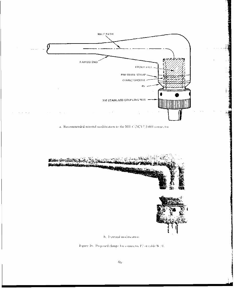
The material used for a water block in the system should not extend intothe stress relief portion of the mold but should be terminated at the end ofthe metal sleeve. Additionally, the stress relief portion of the mold shouldbe faired into the cable rather than terminate as a step at the cable end.The cutout portion of the smaller MIL-C-24217/3-0C1 connector should be elimi-nated, the lines routed up and over, the metal sleeve, and the mold changed toaccomnodate this in a manner similar to that of MIL-C-24231/2-001. A sketchshowing this can be seen in figure 16. It illustrates the 90' termination,the fairing into the cable, routing of the wires around the rear of the metalsleeve, the epoxy water block, a meLali pressure strap, and an 0-ri- kjruouve inthe metal sleeve directly under the metal strap. The metal strap is recom-mended since there have been laboratory results (at NUSC) showing that its useapparently aids in the tolerance of the bond to a severe pressure environment.Some results using the strap have shown bond failure in all areas exceptdirectly below the metal strap. Installation of the metal strap can hesimple. One method would be to tighten the strap so that. the exposed surfaceof the strap just becomes flush with the exterior surface of the neoprene. Abuckle would be used to tie the strap in a manner presently used on manydeep-submersible transducers. A specially designed tool has been fabricatedfor this purpose; details of the tool are available from NOSC.
Although the results of this investigation have shown no dramaticallyconclusive single mode of failure for all cables, the results have led to aconsiderable number of modifications to the system as being desirable if notcompletely necessary. In addition to the above modifications to the 90'connector, some modifications are also considered necessary for the inlineconnectors. These include continued use of the 450 termination of the moldingin the vicinity of the nut, and the use of both the O-ring groove and thestainless steel pressure strap. In addition, the mold should be tapered intothe cable as in the 900 connector. The coupling nut should also be changedfrom nickel-aluminum bronze to 316 stainless, and teflon tape should be usedto prevent thread galling. These are all changes to the present system. Anartist's concept of the recommended connector is shown in figure 16. Althoughthere has been only one known failure due to flooding of an inline connector,our results indicate that there is a high probability that in the future, morefailures of the same type will occur in the inline connector.
4V5
WitLF PAI H
PRESSURE STRAP P1I-7
0-RING G;ROUV1
316 STAINLESS COUPLING NUT -
aI. RecommenICIded jnicuiII(dIIIoddicflI1 t (he %ill 7u ( 41j -0t)] L(ul Icc ]
463
APPENDIX A: CABLE BONDING FAILURE
This appendix consists of a report on some detailed backqroimnd related tothe bonding failures found on these cables. The report contains some discus-
_ sion of other possible design considerations for improving the present cablingsystem. It was originally issued as an informal test report and is includedhere essentially intact.
ij
I
¶ I
I
I'11
S~I
5 Feb 80
By Paul HendersonNWSC Crane
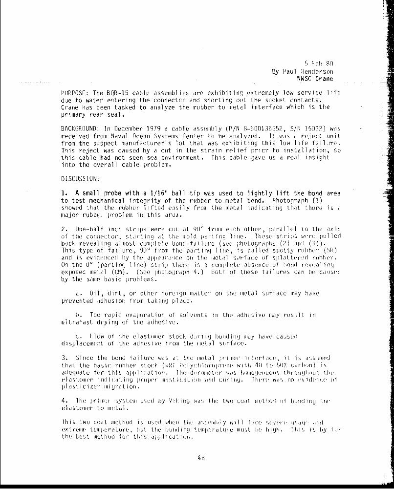
PURPOSE: The BQR-15 cable assemblies are exhibiting extremely low service lifedue to water entering the connector and shorting out the socket contacts.Crane has been tasked to analyze the rubber to metal interface which is theprimary rear seal.
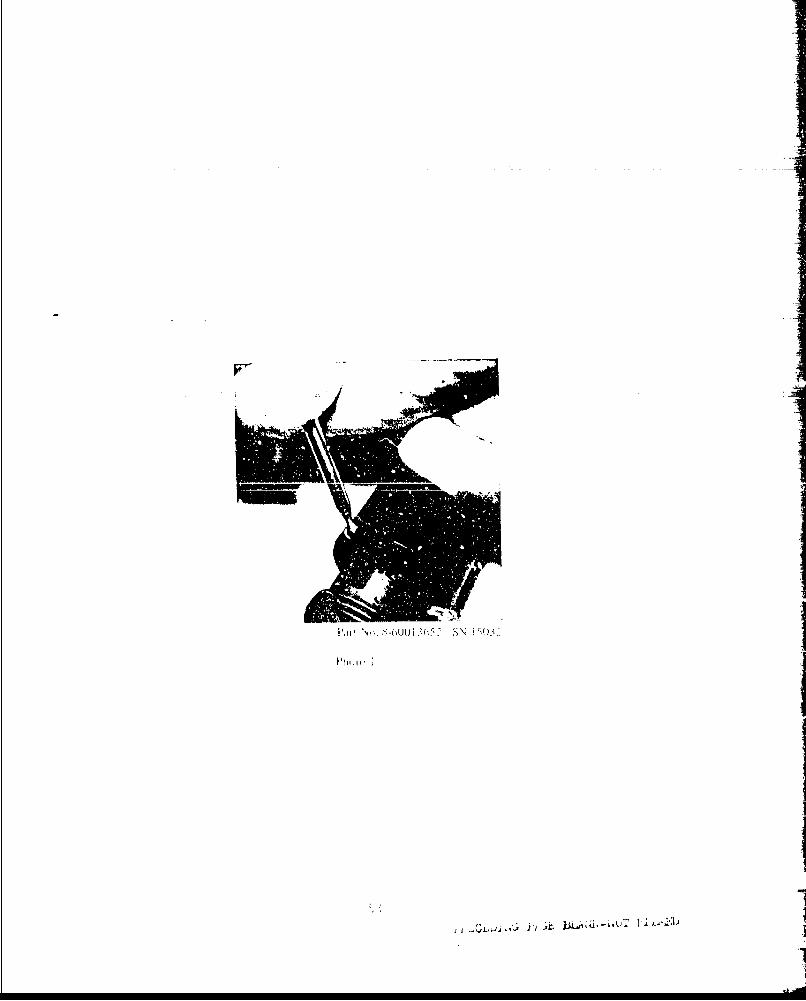
BACKGROUND: In December 1979 a cable assembly (P/N 8-600136552, S/N 15032) wasreceived from Naval Ocean Systems Center to be analyzed. It was a reject unitfrom the suspect manufacturer's lot that was exhibiting this low life failLire.This reject was caused by a cut in the strain relief prior to installation, sothis cable had not seen sea environment. This cable gave us a real insightinto the overall cable problem.
DISCUSSION:
1. A small probe with a 1/16" ball tip was used to lightly lift the bond areato test mechanical integrity of the rubber to metal bond. Photograph (1)showed that the rubber lifted easily from the metal indicating that there is a1major rubbE, problem in this area.
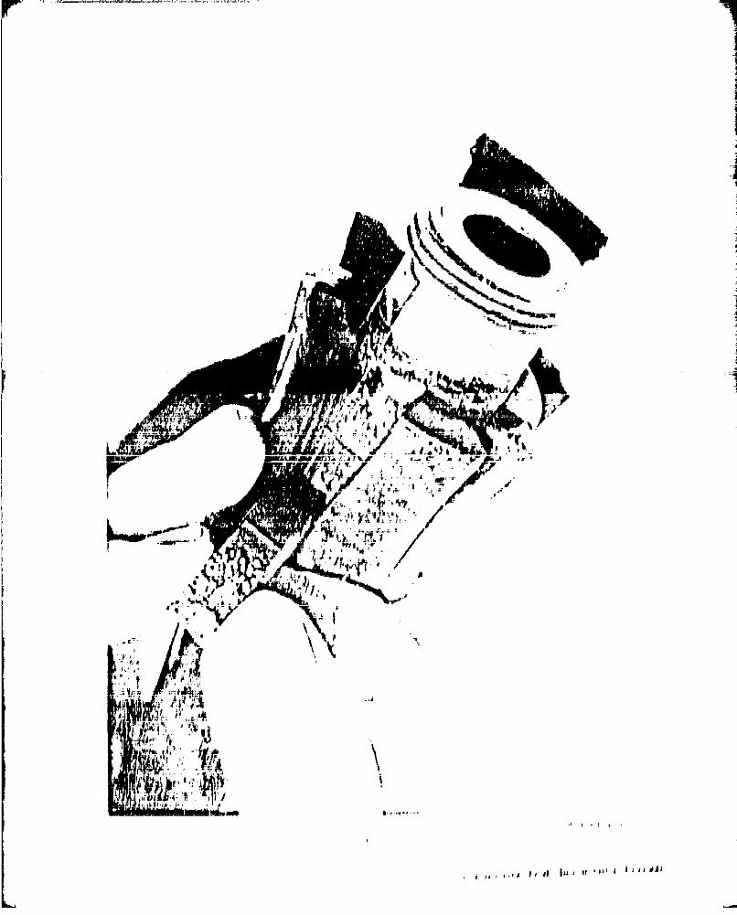
2. One-half inch strips were cut at 90( from each other, parallel to the axisof the coninector, sta:rt-ing at the mol patn lie Th.s -t1p 1ri puback revealing almost coimiplete bond failure (see photographs (2) arid (3)).This type of failure, 90' from the parting 1 irie, is called spotty ruhbbr ( Shiand is evidenced by the appearanice on the iietal sarface of splattered rubher.On the 00 (partin line) strip there is a comiplete absence of hond roevalinrgexposed iietal (CM). (See photogra ph 4.) Both of these tailures cari be causedby the same basic problems.
a. Oil , dirt, or, other loreign matter oun the iiLetal suroace may hiaveprevented adhesion froii taking place.
b. Too rdmlid evaporation of solvents ii the adhesive nay result iru t~rdfast drying of the adhesive.
c. [low of the elastouier stock durlflg bo01drig(J May have causeddisplacement of the adhesive from the metal surface.
3. Since the bornd IailUre Wds a!t the miietal pri'rire ,teri ace, it is rsuilime('dthat the basic ruhber stock (WRI Polychloirop)rerie with 40 to 50% (:di'lhori) isadequate for this appllication. lhe duromi(ter was hoIiiog(nnious througholut theelastomer inrdicatinrg proiper iiasti cation and curing. 1here wis no e ideuce olplasticizer migration.
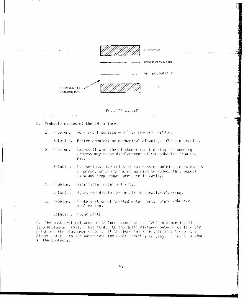
4. lhe priiiier syslteni used by Vikinrg wms the two 'oýi. th) hur di bonudiriy th('el astomer to iieLal,
lhis two coaL miiethod is used when the a,'.,rmbl y will iace- sevre ram'p 'Irdextremire tumpeirature , lout the hordidrg t('imlerciture imiusAt be high. 1111is is by i &rthe best iiiethod for this jipplicatioy.
48
- ~RUBBER (A)
____________ - COVER CIVEMENT IC)
-- P -%tR CEMENT (P)
FAILUORE (CM)r
TWC MýT C
5. Probable causes of the- CM faýilure:
a. Probl em. Poor metal surface - oil or Hovlery residue.I
Sol ut".ion. Better chemical or [mechanical clean]ing. Check operation.
b. Prot)l em. Excess flow of the el ast-omr Stock, dun og( the bondingprocess may cause di sfl acement. of the adhesive fromi themetal.
Sol utiun. Use semnipusi live molds if coII~pCCSSi on molding~ t'echnique isregui red , or use, t'rans fer mu] di ng to redirc.a th is exc''ssfl1ow and] keep proper pressuore in Cayiiy.
c. ProblIemN. Sacrificial metal act ivity.
Sou~lut un. Avoid the di ss1irrilhor metals in abrjtlve cl eoli ng.
d . Prohl emji Conterli not ioni of trr~a 1ted metal jarts before jdhes iVI?OjpIll icoti oil.
Sol ut Ion . Lover parts.
c; 1he must. Criticail area of f aill re occul or s ath1 IRO i' iuol d part.iq 100 1(1
k(See PhotogIraph (). lhi s is, due to the spiall istarrr ( lrntvweei cal] -, entr y11ullni 111(d theP riý j.IIIuurr C utoff . I f t.he lund I a ii 1 rýin thi s area the-re is adirect, entry oh10 loe water into the coabb auhl (,,wit inr, dt 1Iat hr
ini the Col)ItcI(Al.$
7. Some other changes to improve the product might be considered.
a. Add a test for integrity of the hond. such as a pry test, to thespecification fur this connector (MIL-C-24217 (SHIPS)). This would be a 1010test requirement.
b. Add a peel test to paragraph 3 on a sample basis to prove out
production process.
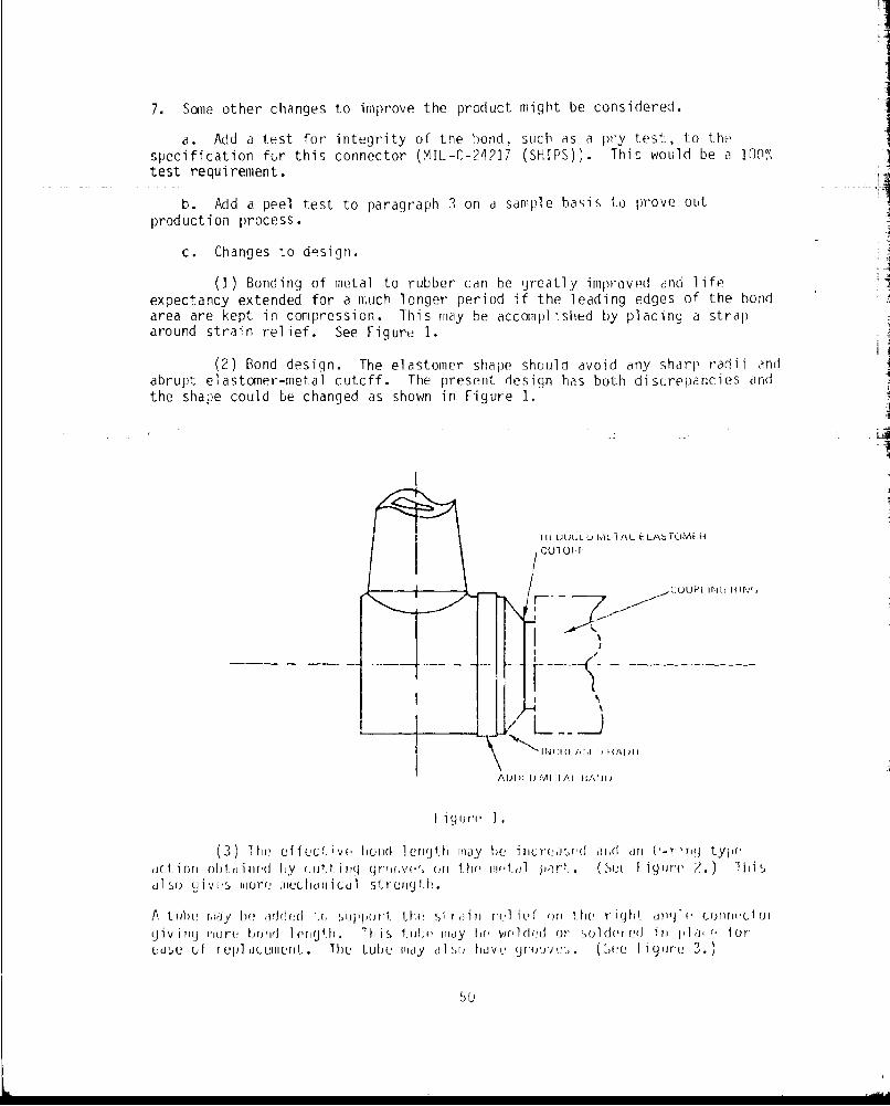
c. Changes to d-sign.
(]) Bonding of metal to rubber can be greatly improvmd and lifeexpectancy extended for a much longer period if the leading edges of the bondarea are kept in compression. This may be accomplished by placing a straparound strain relief. See Figure 1.
(2) Bond design. The elastomer shape should avoid any sharp radii andabrupt elastoner-metal cutoff. The present design has both discrepancies andthe shape could be changed as shown in Figure 1.
HL JUU1,VJ NI.L I AL LLtAbTuML-/CUTOýAF
r:uiLJPi rj(, H "IN',
........ ý
IrJ(: II f,:iI , 11 kI jI I
AI . 1) MI 1/,,IA. iAffl)
I igur(' ].
(3) 1he effect ivy bonld length may be increased ard arn (-rOinrg tyl,(uction ohtained Ly cultin qr (jr',(jrv oil the rrEt.dl owr't. (. ( S igurc ?.,) ihli
dlso giv s tore rIII holr ical strong th.
A t 1h, rlay be ade e I(I .( supprt. t1he si r1;i. l Y r ,1 ief orr the r ight 'org(1 e couirrr Uortgiv iV I� rIore hbowd 1 v'F1( h it' I his 1,111W ittoy be Wr,1 (d d ot sol der eJ ii ln I .- i orUdse oi rel l to.e(J"ni., . ie tube Fray l1 hdb ' griO1'.,. ( ue li gtr. 3.)
The tLI)-'11dy lý) 5b V(
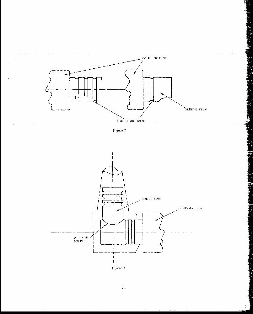
--COUPLING
RING
SLFEVL-, PLUG
AIDULD UROOVLS
J CUUPI IN(, HIM,
I. ,SO I /__--I r--½
VAN''
i, UTq lI
II
~tf~ t -o
1½1
4:I
\. hr..
I' \\'
I Ii it� iL.nu'-iUi IA .A41.kJ
- .,,...�' �.IaIa rr i. - - - -
II
________________________________________ I
F -- -. -II
* JA I
Ii *-�.-�flTh - I1%. 41I I
t I
4� �' t�¶ V
1
� I
A
I
I
I
/
I I I'
A'' IIY U. Ali/ VQ'.-1 P. LAtL[L I A I W I'L ANA[ Y'J I 'j ML [II ~If: U IP I1
.1 h ppurld 1A Lwil" I ýt6 u f a F C!pw of# d viv~eI I ;i held at HUSC frjr the---pur Ole ui t -c'1ving con'structive' criticism on thr mptrhor1 uo'vd foir thr~ f1all're -
Ch1~10 y l Of)[: OtL ili I 1e I I'L' Nix 2rictido LoI , pif. 1:ut l1, Iii t i t tjwor I. I II( 1 udo! I!Of.ill 411r ] utrjij It IIN I 1,' 1, i 14,1 1 , 1S14ft n; li, 0 1 SI I p 1r'I Vdil 101 dl Ir V u.W'. ', ~I' vi o 1,IL W? I VI, Wil J'. 0, 1~i~. LUrjiii. O IvI ( .r1i~rl v j i s L r vqi 1~ If1l ly ¶ ,wjLA0o o dil
II Uj'!ir t Miid I I r(.. Ud'd I'Lr L II!W.,LL
L2
AN/BQS-15 CABLE FAILURE. ANALYSIS MEETING REPORT
by I. -L. Lewis
The test plan for the cable failure program was presented and discussed.Seve ral of the attendees ind ccted that they would forward written comments.
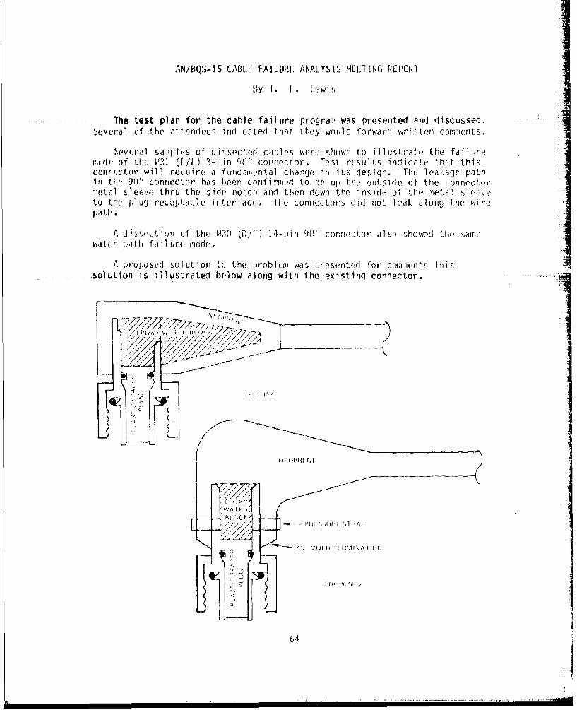
Sevveral sampqles of di'.sected cables were shown to illustrate the failurenodle of the W31 ([)/I ) 3-1 in 90' connector. Test results indicate- that thisconne:ctor will require a fundamental change, in its design. The leakage pathin the 901" connector has been confirmnd to I)e up the, outside of the onrnectormvetal sleeve thru the side notch and then down the inside of the metal sleeveto the plug-lreuutac1(2 iruterlaice. The connectors did riot leak along the wirepath.
A dissectioe of the. W30 (D./1) 14-pin 90" connector also showed the safmewater path failure rode.
A prouposed solution to the problem was presented for cconments Thissolution is illustrated below along with the existing connector.
-/, -PO'--'-
_i__.__
1 0I~ ~ ~ ~ vf I I I/ //////
(4$-j OPH{I us -
LV; jL II(JI'I H (r
S[j
£4
A principal fault with the existing 90' connector emanates from the layingup of the epoxy water block. The volume encapsulated in the conical strainsection has several problems related to it:
1. _ It reduces the minimum neoprene bond water path from an available3/8 inch to 1/4 inch.
2. It does not allow the strain relief section to function as designed.
3. It is not layed up uniformly.
4. All dissected pieces showed cracking of the water block closest to theconnector metal sleeve near the wire entry notch.
Concern was raised at the meeting about the proposed pressure strap. Thismethod is presently under development at NUSC (Charley O)lds). Its use willstop leakage even if the neoprene bond failed. Similar straps have been usedfor years on somne transducers. The implementation of the strap here howeverneeds design, material, and installation development.
Lnclosure (]) Io NOV(SC 1tr Ser 03 3/?4
65
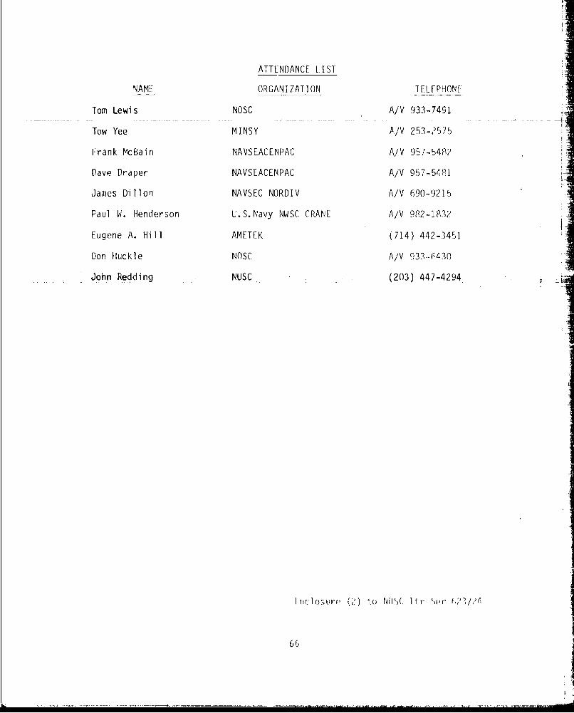
ATTENDANCE LIST
NAME ORGANIZATION T El_ PHON F
Tom Lewis NOSC A/V 933-7491
Tow Yee MINSY A/V 253-2575
Frank McBain NAVSEACENPAC A/V 957-548?
Dave Draper NAVSEACENPAC A/V 957-54i81
James Dillon NAVSEC NORDIV A/V 690-9215
Paul W. Henderson U.S. Navy NWSC CRANE A/V 982-I03?
Eugene A. Hill AMETEK (714) 442-3451
Don Huckle NOSC A/V 933-6430
John Redding . -NUSC - (203) 447-4294
I 1d o ,ur' L, ) ii, c ) r ' r f
66
orUAv 126/,' A* S 0)
SJN O1O?.L-F-776-5097
DEPARTMENT OF THE NAVY
Memorandum 270.3-Ser. 318
DAIE: 2 Marh 198
FROM: Tow Yee, Code 270.301, NAVSKIP1YOMAREi
TO0: Tomn Lewis, Code 6231, Naval Ocean Systems Center
SUBd: AN/BQS-15 Cable Failuire Analysis Meeting, Commrents of
REF: (a) N1USC Lt~r, TLL:cyXA57 Set'. (S?3/?4 of 13 Feb 1980; SuhI:ArN/BQS-15 Cable Failure Analysis Meeting
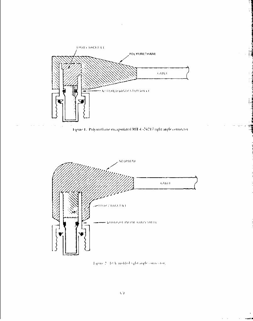
End: (1) Sketch: a) fi 9 (1) Polyurethane encapsuilate-d MIL-C-24211Right Anqle Connector
b) fig (2); Deep Submrergence Right Angle ConnectorAssembly.
I. As d s c us soý(,d a ref en re nc ce ( a ' AN'/110S - 15 C a 1l 1 o a i Ii jire A na 1 ys i - ment n qthe, M I -C-?421 I ri qiht-anol f, connect i ons were, 12 ocd i no. The conriectors have aIhard epoxy hackf i 11 and cabl e stra in rel ief , and are, enc apsi!lal 0in neopre norubýber. falor nalysis idr'nlitieid ft oudingq vias. caujsod by rubber to metalbond seporation and tract~ure of 1,ho hard epoyy cable, re Tel a! the coimrloC ,ishell1 . Coirrvients on sol utiions and M IL-C-?4] 7 ri gql. a ngl (, connector servicdat a were reqiuested.
?.The, MIL-C-?4?17 H ight. angle connector is Ogi(i (lid on th 1 /f.1wSubmarine, Distress P~inr (,r transducers , and 01ce dveej soiil)[riergnce vehlic-les((DSV's) N1p-1, DSV -3 (TUIIJ) ), [ISV-1 ( H~sI l) , and lhfe ileel !p mrgnirescuetj ve~hicles (I)kV's) . 1 he cahll i connector asorlyihlo (.( nsial lid on) l~e(ISVs are reliableý and have( not. e/eirie he falreiodr- exJh Viy 0hwAN/E"QS-IS) cabler connoct~or asrb n.1he- nISV curirieclu a:;siiilil ews aresubje'(c1ed t'o 0. Sk fooul dejiths wi tholil si oniTi cant. Iail1 re', arid are -o i'Iiand rejl aced nrwiri al ly every S er. ew nrc~r rincrrror"It i a hard epoxybackf ill and pulyrcethairir[ for sifra in rol ief and ecptltin
3. VIe conicur wi.1 1.11the faJillj-' r 'rm aoly~i. f Iirl"id iiJ that the ll/PS-' iconnectur asseirbi if-, floode-d )t, t.he cuhl( e nii-iicluor . Suljrjw',i Idla t two al lee-natiivir irir~thirio hoi cursi lurid. 1hir riiitOhi do arf- to enir( a a (-oriif- or ,Viiicuiicu aliaorrlie iojra uaSia , olr oie t r'I
polyiirof-haoo, enc(losujre (I ) , fi I, orý" j1.i'jriul K1J '1r I 'l hi rup rd ii ghi. ridnfecta odiri (' 11)loo urc (1) if refeoreo~l.nce(i )i i 10 iIir
-d.fo yiirnh lie r-( iO ( ~I lof r-0rliO rl ii ~'i~r iI
su~r~ur i esirvire !vl oi riij Ily [olili1d rio Ylyriri iwsli oril (- lii -
avail illV rid1i sir f 1r 0 jr~ 12 [it rihe l 1 i (Al/ n rI~ l ori ("I i r 11, 1i I~.
n-ity lii tuy~fhur theueof i nj I oul, v I 1o rh, vi~oulll o~ d a''I ut i rr1Vy
() 1r i~ ( yh (J r'f- (1ý h ol ii wi £1 lt
molds and molding procedures are in service and available for polyurethaneencapsulation of the MIL-C-24217 right angle connector.
5. Right angle connector assemblies similar to the proposed method detailed--in enclosure (1) of reference (a) has been in service on the flSV's NR-1 and
DSRV's with satisfactory resolts. See fig 2 of enclosure (1). The connector -i
assemblies are repeatedly sub. ected to 6.5k foot depths without significantfailures. The connector assemblies installed on the NtP-I and DSRV's do notincorporate pressure bond straps and in service data is not available. Theproposed encapsulation method has more available connector bonding surfacethan the MIL-C-24217 right angle connector, and eliminates the stress fracturefailure at the cable strain relief area. The proposed connector assembliescan be installed in areas where vertical clearance is not critical.
6. Cable failures and reliability can be improved with quality controlprogram and proper material choice. Surface preparation and elimination of Ithe hard epoxy strain relief area would eliminate a majority of problemsencountered.
I£ I~ )
I
I 14)X i ACK ILLI
POLYUJRE' H ANIL I
i,>/, ?,. ,, 'FF
___ ~ ~ ~ 1 A IL I t~rt C-I'F I
/
J./J ""I I/ Ifl :I I fl ' IF d ,~~f ,1
\ ] •
ii ', rh I hjJ51