Embed Size (px)
Citation preview
AD-AlE? 309 NAVAL Rift STATION DERMUDA FLEET MOORINGS USIERUTER llINSPECTION REPOAT(U NAVAL FACILITIES ENGINEERINGCOMMAND IIASHINOTON DC CHESAPEAKE DIV DEC 81
UNCLSSIFIED C NES/N AYRC F ACFPO±81C1G)F0132tN
EEEEEEEEEEEEEE
MEu.
ISIj.
I ~ AA 12.0.0~!._1
6. ,
iiii . --" ml
IIII IlII -- '1.25 _1.4 11__6
MICRnO(-P' CHART
R - -
.1 I.--.. ....
% Z.
. - - .. ' .. . . ... .- ., - , .

FP()
8118
4. 2F L: L -0,N
.. .. - C,
NAVAL AIR STATION BERMUDA(n FLEET MOORINGSm UNDERWATER INSPECTION REPORT
IN 8-15 JULY 1981
DTICC- LECTE
0 MAYO01 IM
FPO-1-811181 . _,
DECEMBER 1981
°%rllnml sooa Sele
plat~es: 11 , re mU'@dhions w il be Is ""0ulslteo
t..tI.
OCEAN ENGINEERINGAND CONSTRUCTION PROJECT OFFICE
CHESAPEAKE DIVISIONNAVAL FACILITIES ENGINEERING COMMAND
WASHINGTON, DC 20374
swounpom i o&Im Aa - z /toe
".~ ~ ~ ~ ~~~~kud °v* %-. - .%- .•. _ f , t - ,
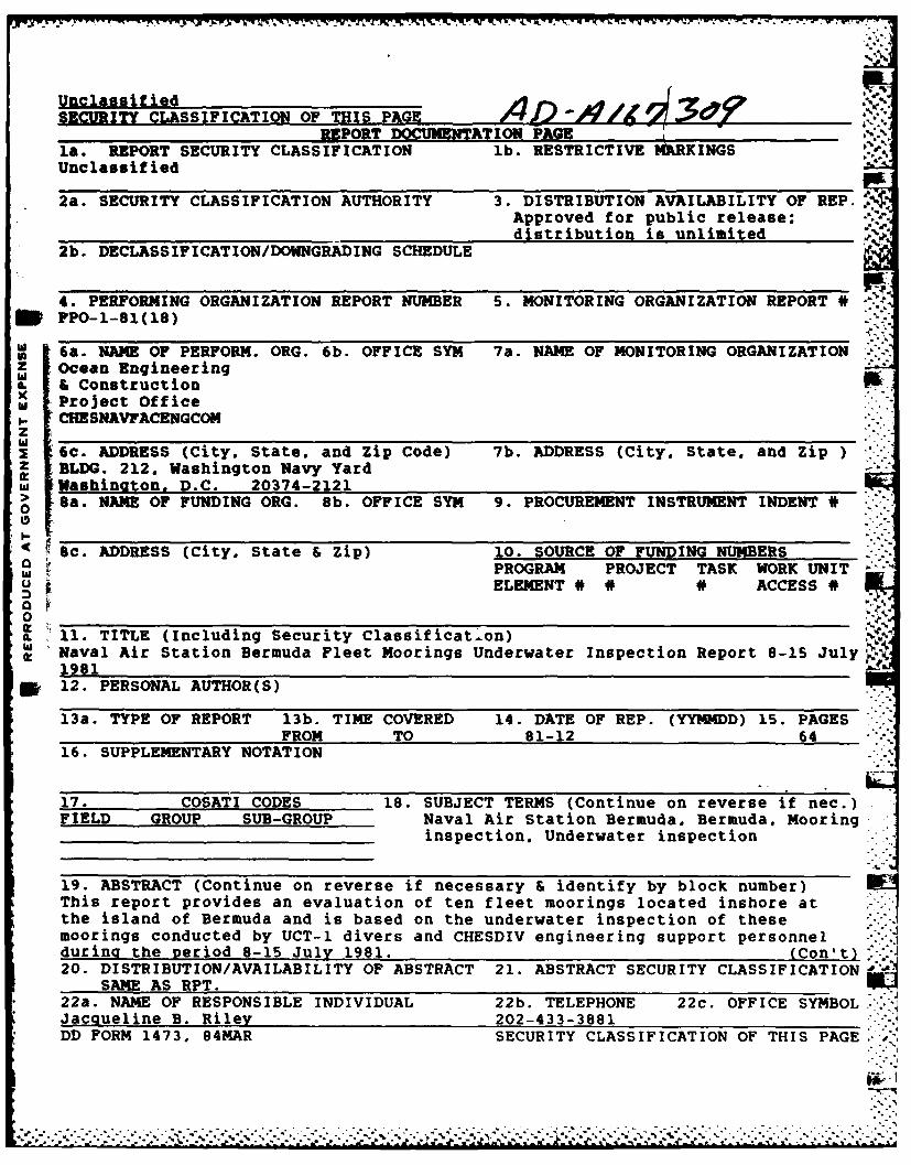
UnclassifiedSECURITY CLASSIFICATION OF THIS PAGE
POT DOCUMENTATION PAGE.la. REPORT SECURITY CLASSIFICATION lb. RESTRICTIVE IRKINGSUnclassified
2a. SECURITY CLASSIFICATION AUTHORITY 3. DISTRIBUTION AVAILABILITY OF REP.Approved for public release;
_____________________distribution is unlimited .
2b. DECLASSIFICATION/DOWNGRADING SCHEDULE d
4. PERFORMING ORGANIZATION REPORT NUMBER 5. MONITORING ORGANIZATION REPORT# -FPO-1-81(18)
i 6a. NAME OF PERFORM. ORG. 6b. OFFICE SYM 7a. NAME OF MONITORING ORGANIZATIONZ Ocean Engineering
L ConstructionProject Office
SCHESNAVFACENGCO.zw 6c. ADDRESS (City. State. and Zip Code) 7b. ADDRESS (City. State. andz-ip )z BLDG. 212. Washington Navy YardW Washinaton. D.C. 20374-2121
Sa. NAME OF FUNDING ORG. 8b. OFFICE SYM 9. PROCUREMENT INSTRUMENT INDENT #
Sc. ADDRESS (City. State & Zip) 10. SOURCE OF FUNDING NUMBERSPROGRAM PROJECT TASK WORK UNIT
ELEMENT # # * ACCESS #
11.TITLE (Including Security Classificat'on)Naval Air Station Bermuda Fleet Moorings Underwater Inspection Report 8-15 July-N1981
* 12. PERSONAL AUTHOR(S)
13a. TYPE OF REPORT 13b. TIME COVERED 14. DATE OF REP. (YYMMDD) 15. PAGESFROM TO 81-12 64
16. SUPPLEMENTARY NOTATION
17. COSATI CODES 18. SUBJECT TERMS (Continue on reverse if nec.)FIELD GROUP SUB-GROUP Naval Air Station Bermuda. Bermuda. Mooring
inspection, Underwater inspection
19. ABSTRACT (Continue on reverse if necessary & identify by block number)This report provides an evaluation of ten fleet moorings located inshore atthe island of Bermuda and is based on the underwater inspection of thesemoorings conducted by UCT-1 divers and CHESDIV engineering support personnelduring the period 8-15 July 1981. (Con't)20. DISTRIBUTION/AVAILABILITY OF ABSTRACT 21. ABSTRACT SECURITY CLASSIFICATION
SAME AS RPT.22a. NAME OF RESPONSIBLE INDIVIDUAL 22b. TELEPHONE 22c. OFFICE SYMBOL.."'Jacqueline B. Riley 202-433-3881DD FORM 1473, 84MAR SECURITY CLASSIFICATION OF THIS PAGE
.. -............-. . . "._.. .,...-.... -* * -'.- - -- . . .' ' - .".
Div i
Div 01NAVAL AIR STATION BERMUDAFLEET MOORINGS
UNDERWATER INSPECTION REPORT8-15 JULY 1981
FPO-1-81 (18)DECEMBER 1981
OCEAN ENGINEERINGAND CONSTRUCTION PROJECT OFFICE
CHESAPEAKE DIVISIONNAVAL FACILITIES ENGINEERING COMMAND
WASH INGTON, DC 20374
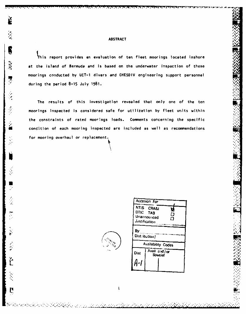
ABSTRACT
'This report provides an evaluation of ten fleet moorings located Inshore
4/ at the island of Bermuda and is based on the underwater inspection o hs
moorings conducted by UCT-I divers and CHESDIV engineering support personnel
* during the period 8-15 July 1981.
The results of this investigation revealed that only one of the ten
moorings Inspected is considered safe for utilization by fleet units within
the constraints of rated moorings loads. Commients concerning the specific
condition of each mooring inspected are included as well as recommiendations
for mooring overhaul or replacement.
Accesion For
NTIS CRA&jTIlC TAB3
UnannoulcedJustificatioii
BY
Availability Codes
Ai vail ajd/o 0Dit Special!
A-1.
.. . . . .. . . . . . * . . . * *~. . .-7
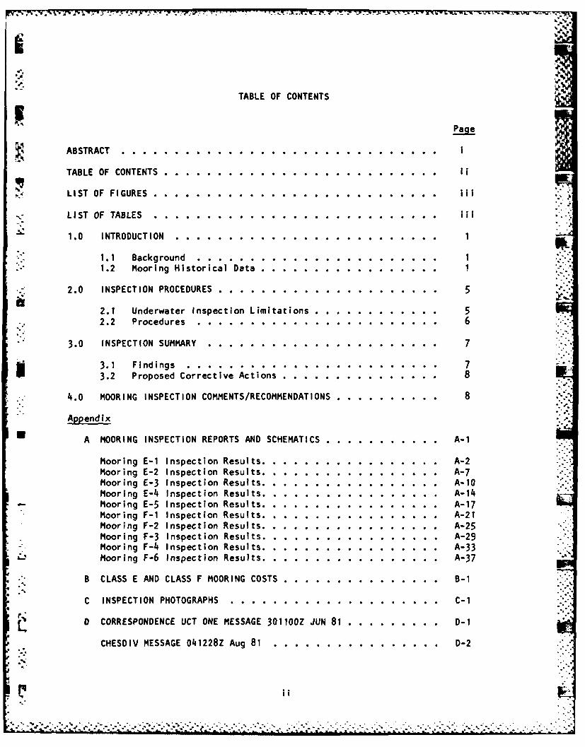
TABLE OF CONTENTS '
Page
ABSTRACT. .... ............ ............ ... I
TABLE OF CONTENTS .. .... ........... .. .. .. ... . FI
LIST OF FIGURES . . .. .. .. .. .. .. .. .. .. .. .. . . ..
LIST OF TABLES................... .. ...... . . ... .. .. . . ....
1.0 INTRODUCTION.................. . . .... ... .. .. .. .. .....
1.1 Background...............0 . . ... . . . .. .. .. .. ... 11.2 Mooring Historical Data.... .. .. .. .. .. .. .. .. .
2.0 INSPECTION PROCEDURES. .. ......... ............ 5
2.1 Underwater Inspection Limitations .. .... ......... 52.2 Procedures . . . . .. .. .. .. .. .. .. .. .. .. 6
3.0 INSPECTION SUMMARY .. ......... ............ 7
3.1 Findings.........................7S3.2 Proposed CorrectIv Actions............. 8
4.0 MOORING INSPECTION COMMENTS/RECOMMENDATIONS. .. .......... 8
Appendix
A MOORING INSPECTION REPORTS AND SCHEMATICS. .. .......... A-1
Mooring E-1 Inspection Results .. .. ........ ..... A-2Mooring E-2 Inspection Results .. .. .... ........... A-7Mooring E-3 Inspection Results .. .. ........ ..... A-10Mooring E-4 Inspection Results. .. .... ............ A-14
-Mooring E-5 Inspection Results. .. .. ......... ... A-17Mooring F-i Inspection Results .. .. .... ........... A-21Mooring F-2 Inspection Results .. .. ........ ..... A-25Mooring F-3 Inspection Results. .. .... ............ A-29Mooring F-4. Inspection Results. .. .... ............ A-33Mooring F-6 Inspection Results. .. .... ............ A-37
B CLASS E AND CLASS F MOORING COSTS. .. ......... ... B-1
C INSPECTION PHOTOGRAPHS .. .. .. .. .. .. .. .. .. . .C-i
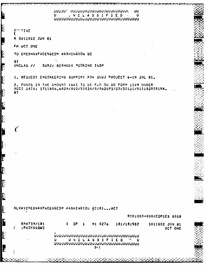
N 0 CORRESPONDENCE UCT ONE MESSAGE 30110OZ JUN 81. .. ........ D-1
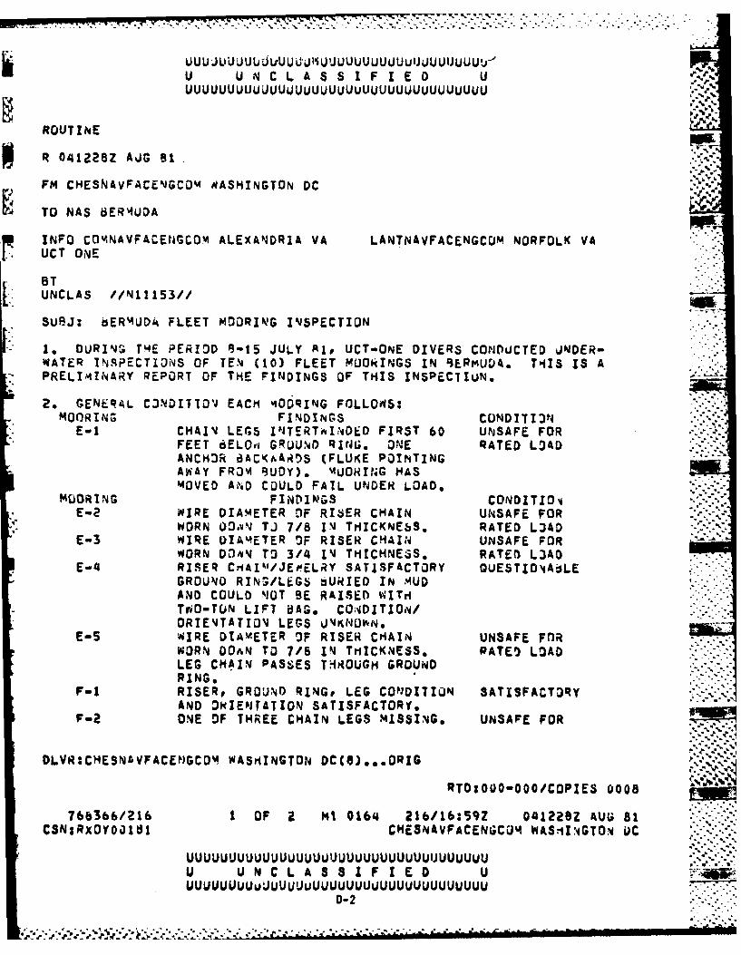
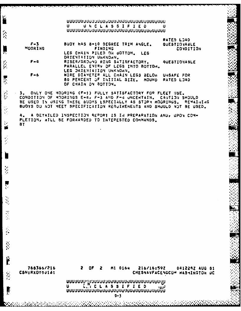
*CHESDIV MESSAGE 041228Z Aug 81. ...... ........... D-2
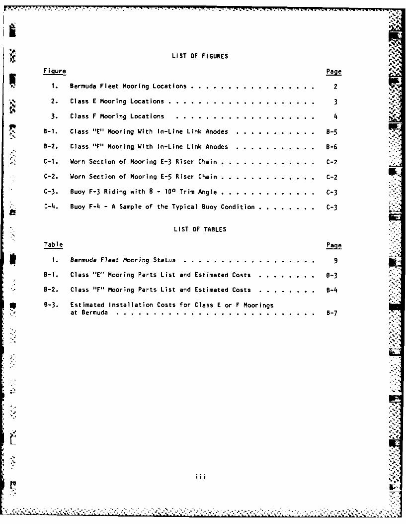
LIST OF FIGURES
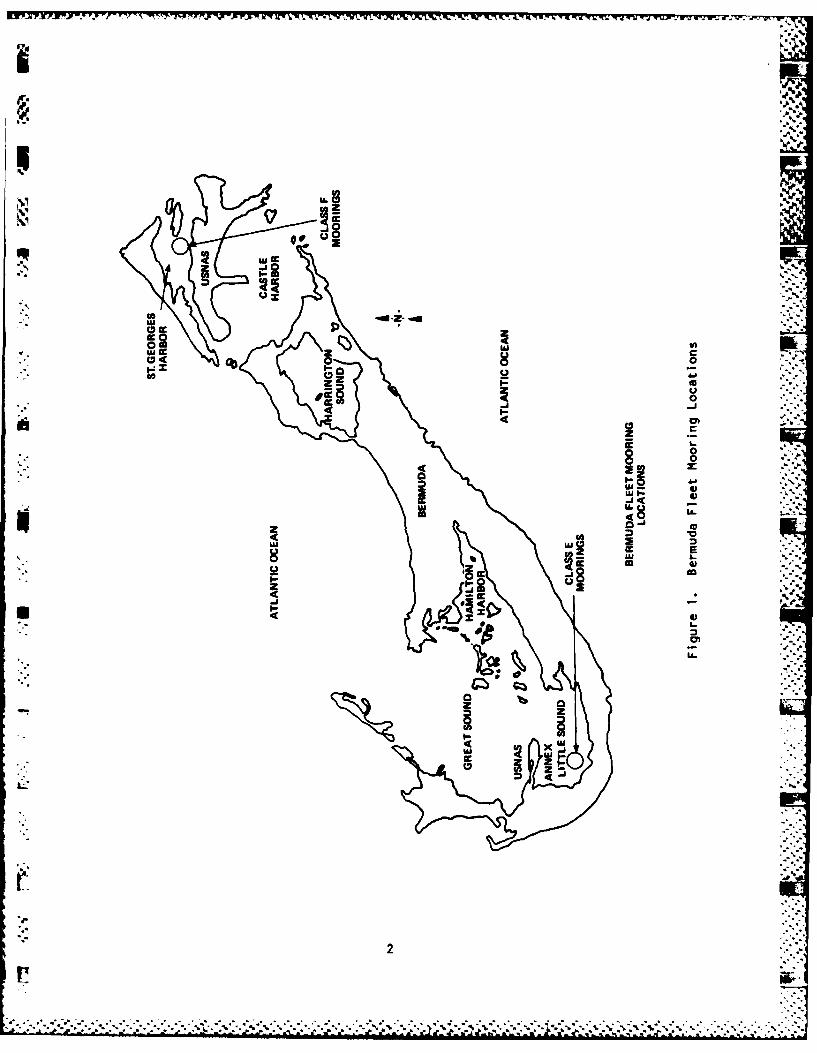
F1.r Bermuda Fleet Mooring Locations. .. ......... ....... P2
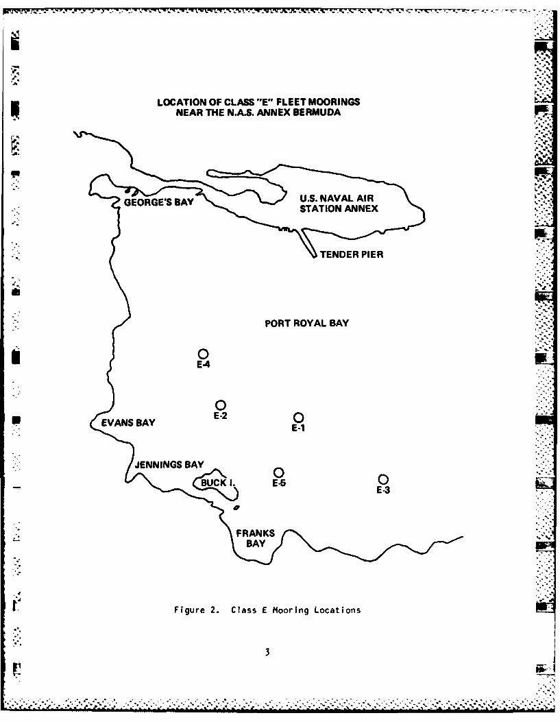
% 2. Class E Mooring Locations. .. .......... .......... 3
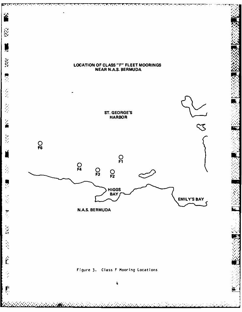
3. Class F Mooring Locations ...... ........... ..... 4
B-. Class "E" Mooring With In-Line Link Anodes .. ............-5
B-2. Class "I"' Mooring With In-Line Link Anodes. ..... .......-6
C-1. Worn Section of Mooring E-3 Riser Chain .. ..... ........ C-2
C-2. Worn Section of Mooring E-5 Riser Chain .. ..... ........ C-2
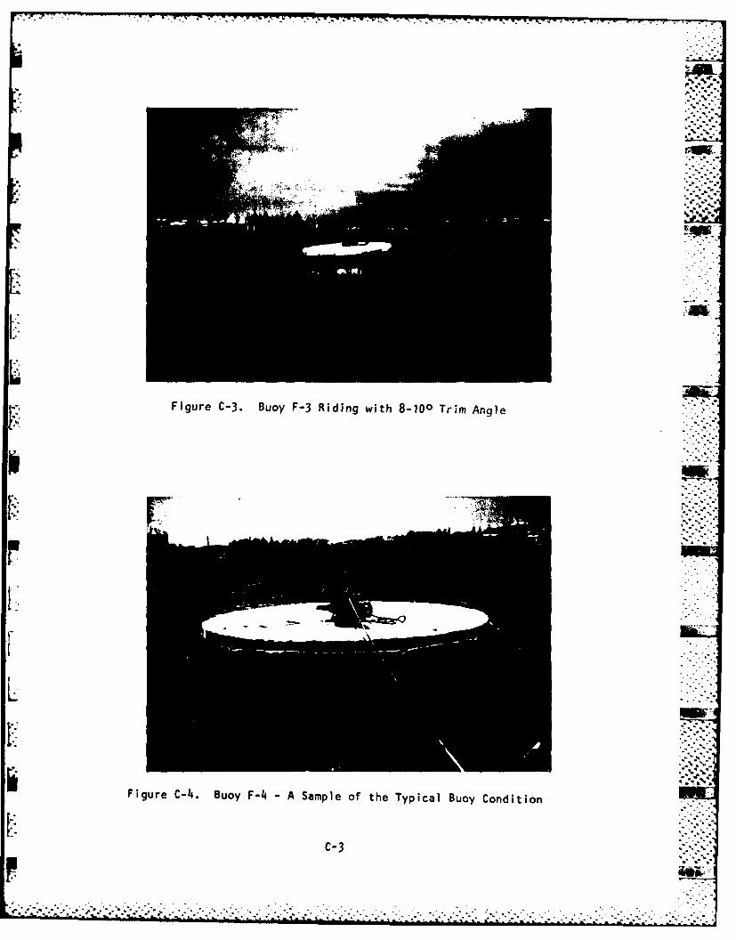
C-3. Buoy F-3 Riding with 8 -100 Trim Angle .. .... ......... C-3
C-4.. Buoy F-4. A Sample of the Typical Buoy Condition. .. ....... C-3
LIST OF TABLES
Table Page
1. Bermuda Fleet Mlooring Status .. .......... ......... 9
B-1. Class "E" Mooring Parts List and Estimated Costs .. ........ 8-3
B -2. Class "F' Mooring Parts List and Estimated Costs .. ........ B-4.
B-3. Estimated Installation Costs for Class E or F Mooringsat Bermuda. ..... ............ ............- 7
(.7
NAS BERMUDA FLEET MOORINGS
UNDERWATER INSPECTION REPORT
1.0 INTRODUCTION
1.1 Background. By message, on 30 June 1981, Underwater Construction Team
One (UCT-1) requested CHESNAVFACENGCOM to provide on-site engineering support
during the scheduled inspection of fleet moorings at Bermuda. A total of ten
moorings were inspected, five "E" class located in Port Royal Bay in the
Little Sound south of the Naval Air Station Annex (see Figures 1 and 2) and
five "F" class in St. George's Harbor north of the Naval Air Station (see
Figures 1 and 3). CHESNAVFACENGCOM was requested to provide inspection
planning and on-site engineering support, to collect the raw data gathered by "'
UCT-1 divers, to analyze this data, and to prepare the inspection report.
1.2 Mooring Historical Data. The underwater inspections of these moorings
were conducted during the period 8-15 July 1981. Upon arrival on island, a
meeting was held with personnel of the NAS Public Works Department (PWD) to
obtain and review all available data concerning the usage and maintenance of
these moorings. Copies of reports of two previous underwater mooring
inspections, conducted by local contractors during 1978 and 1980, were made
available to CHESNAVFACENGCOM personnel. It was determined by UCT-1 divers
that the wire diameters of the mooring material detailed in these reports did
not reflect the sizes of the material actually in the water, and these reports .5..';
were subsequently disregarded as being erroneous. e
.............................................................
P7 - jr jrj W irw VI 1. VV-WV'.IVN -4J J17% W - V ;..5 it 9 -. 7 v TV RIE T. TV TI -. TVw
*U W
0 cc s -
Dj W
00
x 1-0to0
4 cc0 I-8
JEE
8j ui LLcc L--.
U U,4 ccl *-
I-L* 4 b 43
- .. -- - -. -- - - - - -7%7- - r1rr--w-u--7.
LOCATION OF CLASS F"E" FLEET MOORINGSNEAR THE N.A.S. ANNEX BERMUDA
PORT ROYAL BAY
E4
pVNSA E-2QE-1
JENNINGS BAY
BUCK .E0E -3
Figure 2. Class E Mooring Locations
3 j
9'J)'
j LOCATION OF CLASS "F" FLEET MOORINGS bj
NEAR N.A.S. BERMUDA
F44
BAY'a
Z7'*
Ile'ST GEORGE.'S.
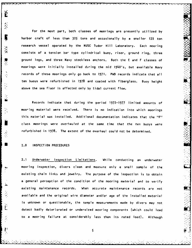
For the most part, both classes of moorings are presently utilized by
harbor craft of less than 325 tons and occasionally by a smaller 120 ton
research vessel operated by the NUSC Tudor Hill Laboratory. Each mooring
consists of a tension bar type cylindrical buoy, riser, ground ring, three
ground legs, and three Navy stockless anchors. Both the E and F classes of
moorings were initially installed during the mid 1940's, but available Navy
records of these moorings only go back to 1971. PWD records indicate that all
ten buoys were refurbished in 1978 and coated with fiberglass. Buoy height
* above the sea floor is affected only by tidal current flow.
Records indicate that during the period 1972-1977 limited amounts of
. mooring material were received. There is no indication into which moorings
this material was installed. Additional documentation indicates that the "F"
class moorings were overhauled at the same time that the ten buoys were
refurbished in 1978. The extent of the overhaul could not be determined.
n 2.0 INSPECTION PROCEDURES
2.1 Underwater Inspection Limitations. While conducting an underwater
mooring inspection, divers clean and measure only a small sample of the
existing chain links and jewelry. The purpose of the inspection is to obtain
a general perception of the condition of the mooring material and to verify
existing maintenance records. When accurate maintenance records are not
4- available and the original wire diameter and/or age of the installed material
is unknown or questionable, the sample measurements made by divers may not
Li detect badly deteriorated or undersized mooring components (which could lead
* .to a mooring failure at considerably less than its rated load). Although
5
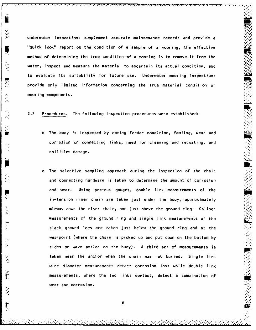
underwater inspections supplement accurate maintenance records and provide a
5 "quick look" report on the condition of a sample of a mooring, the effective
method of determining the true condition of a mooring is to remove it from the
,2 water, inspect and measure the material to ascertain its actual condition, and
to evaluate its suitability for future use. Underwater mooring inspections
provide only limited information concerning the true material condition of
-" mooring components.
2.2 Procedures. The following inspection procedures were established:
o The buoy is inspected by noting fender condition, fouling, wear and
corrosion on connecting links, need for cleaning and recoating, and
collision damage.
o The selective sampling approach during the inspection of the chain
and connecting hardware is taken to determine the amount of corrosion
and wear. Using pre-cut gauges, double link measurements of the
in-tension riser chain are taken just under the buoy, approximately
midway down the riser chain, and just above the ground ring. Caliper
measurements of the ground ring and single link measurements of the
slack ground legs are taken just below the ground ring and at the
wearpoint (where the chain is picked up and put down on the bottom by
tides or wave action on the buoy). A third set of measurements is
taken near the anchor when the chain was not buried. Single link
wire diameter measurements detect corrosion loss while double link
measurements, where the two links contact, detect a combination of
wear and corrosion.
-. 6
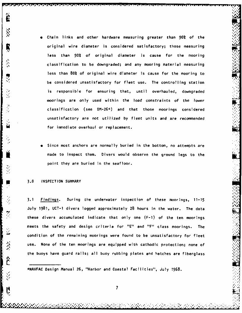
* Chain links and other hardware measuring greater than 90% of the
original wire diameter is considered satisfactory; those measuring
less than 90% of original diameter is cause for the mooring
classification to be downgraded; and any mooring material measuring
less than 80% of original wire diameter is cause for the mooring to
be considered unsatisfactory for fleet use. The controlling station
is responsible for ensuring that, until overhauled, downgraded
moorings are only used within the load constraints of the lower
classification (see DM-26*) and that those moorings considered
unsatisfactory are not utilized by fleet units and are recommended
for immediate overhaul or replacement.
9 Since most anchors are normally buried in the bottom, no attempts are
made to inspect them. Divers would observe the ground legs to the
point they are buried in the seafloor.
n 3.0 INSPECTION SUMMARY
3.1 Findings. During the underwater inspection of these moorings, 11-15
July 1981, UCT-1 divers logged approximately 28 hours in the water. The data
these divers accumulated indicate that only one (F-1) of the ten moorings
meets the safety and design criteria for "E" and "F" class moorings. The
condition of the remaining moorings were found to be unsatisfactory for fleet
use. None of the ten moorings are equipped with cathodic protection; none of
the buoys have guard rails; all buoy rubbing plates and hatches are fiberglass
*NAVFAC Design Manual 26, "Harbor and Coastal Facilities", July 1968.
7
,_ .V ,4 . -_, ,-.. --.. . .. . -.-- * -,- . . , .. , -. .-. . . - .. - ,. - -. .. - , .-.-.. .--,* .*,.- • - ,-
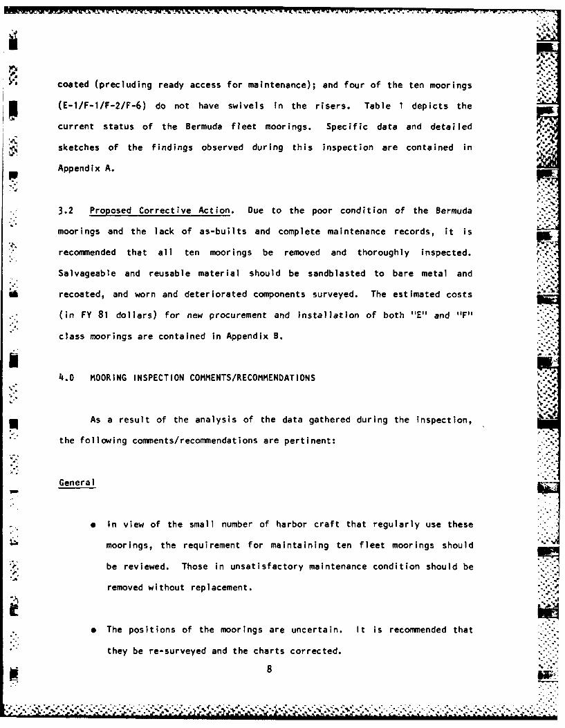
coated (precluding ready access for maintenance); and four of the ten moorings
- (E-1/F-1/F-2/F-6) do not have swivels in the risers. Table 1 depicts the
current status of the Bermuda fleet moorings. Specific data and detailed
sketches of the findings observed during this inspection are contained in
Appendix A.
. 3.2 Proposed Corrective Action. Due to the poor condition of the Bermuda
moorings and the lack of as-builts and complete maintenance records, it is
recommended that all ten moorings be removed and thoroughly inspected. ,
Salvageable and reusable material should be sandblasted to bare metal and
recoated, and worn and deteriorated components surveyed. The estimated costs
* (in FY 81 dollars) for new procurement and installation of both "E" and "F"
class moorings are contained in Appendix B. -.
-.
4.o MOORING INSPECTION COMMENTS/RECOMMENDATIONS
- ~*., ..
As a result of the analysis of the data gathered during the inspection,
the following comments/recommendations are pertinent: -. -.
GeneralIM
e In view of the small number of harbor craft that regularly use these
moorings, the requirement for maintaining ten fleet moorings should
be reviewed. Those in unsatisfactory maintenance condition should be
removed without replacement.
9 The positions of the moorings are uncertain. It is recommended that
S"they be re-surveyed and the charts corrected.
8WC. 8' -*"%.
:..:-,.., ....:-:,.. ; -,, - .. ::..- . ,:. ..,% -..... :,: .:.-, -,,-,,- ,::. , '.:.; .:.;',.% :,,"... . ...-.- : .... : .... .... .,.....m. . ... ....
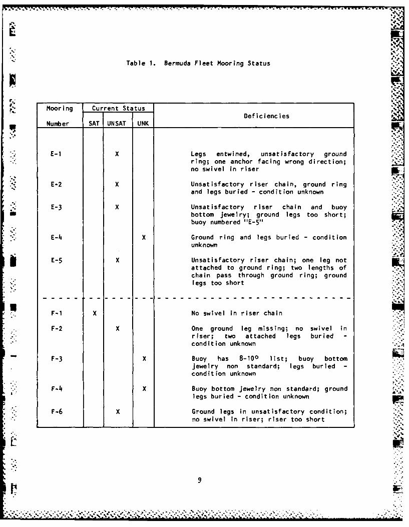
Table 1. Bermuda Fleet Mooring Status
Mooring Current StatusDeficiencies
Number SAT UNSAT UNK IIE-1 X Legs entwined, unsatisfactory ground
ring; one anchor facing wrong direction;no swivel in riser
E-2 X Unsatisfactory riser chain, ground ringand legs buried - condition unknown
E-3 X Unsatisfactory riser chain and buoy
1 bottom jewelry; ground legs too short;buoy numbered "E-5"
E-4 X Ground ring and legs buried - conditionunknown
E-5 X Unsatisfactory riser chain; one leg notattached to ground ring; two lengths ofchain pass through ground ring; ground' ~legs too short : D
F-I X No swivel in riser chain
F-2 X One ground leg missing; no swivel inriser; two attached legs buried -
condition unknown
F-3 X Buoy has 8-100 list; buoy bottomjewelry non standard; legs buried -
condit ion unknown
F-4 X Buoy bottom jewelry non standard; groundlegs buried - condition unknown
F-6 X Ground legs in unsatisfactory condition;no swivel in riser; riser too short
9
• •:C7o•° h " ' .j' ° o " . % % o . "% ., ° '• '" ,'
,'A,
There is no cathodic protection on any of the ten Bermuda fleet
moorings. The continuity cable observed was badly deteriorated and
broken in numerous places. The 5/8-inch wire continuity cable
utilized has a fiber rope core. A plastic core type wire rope Is
recommended for use as a continuity cable.
' Accurate as-built documentation of each mooring to be reinstalled
should be prepared and maintained.
o All fleet moorings should be scheduled for continuing periodic
underwater inspections. Preventative maintenance should be performed
as soon as possible after the results of these inspections are
known. Overhauled or new NAS Bermuda moorings should be inspected by
divers immediately after installation to verify that anchors are
properly set, orientation of the ground legs is as designed, and that -
the cathodic protection system is intact.
Buoy
* Buoy bottom jewelry above the riser chain in several moorings do not
comply with sound chain joining practices.
* Rubbing railing (fender assembly) should be installed on buoy tops to
protect buoy and fiberglass coating from damage due to chain movement.
10
~~. _......... .......................,....-,-......;... ... .....-.............. -........... -.-..-...
Riser
* Only one of the ten moorings inspected conditionally meets design
criteria and appears safe for usage by fleet units within rated load
constraints. However, a swivel should be inserted in its riser chain
as soon as possible. The inclusion of at least one swivel in the
riser of a free-swinging mooring is standard practice (DM-26).
. The design length of the combined buoy bottom jewelry and riser chain
should approximate the depth of the water from high tide to the
id bottom less ten feet (DM-26). Excess length of the riser results in
piling of chain on the bottom or the burying of the ground ring and
lower end of the riser. Shortness of the riser causes the ground
ring to ride high above the sea floor and results in the buoy
supporting additional ground leg weight in the water column.
L
. . . . . . . . . . . . . . . . . . . . . .
APPEND IX A 5
MOORING INSPECTION REPORTS AND SCHEMATICS
* ~The following sections contains the inspection data and a schematic 5.
drawing of each of the ten Bermuda fleet moorings inspected. The data
* *~ outlined in each Appendix are a summnary of the information obtained by the
UCT-1 divers and on-site CHESNAVFACENGCOM support personnel.
A-1
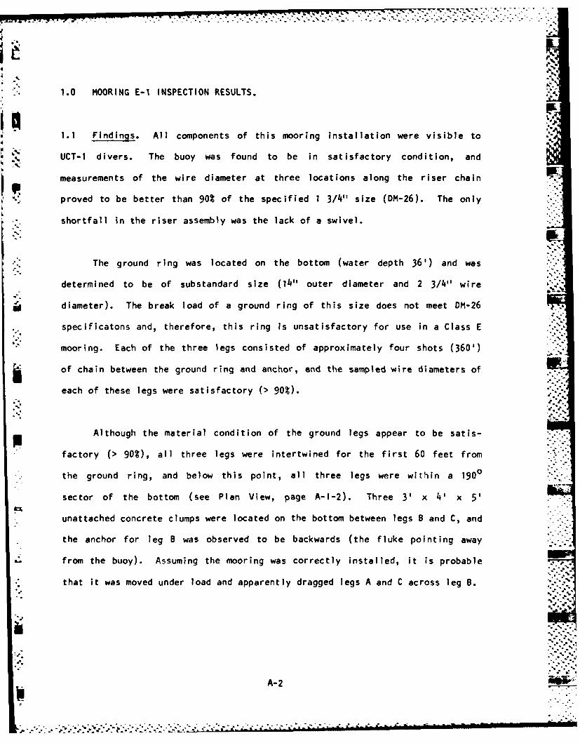
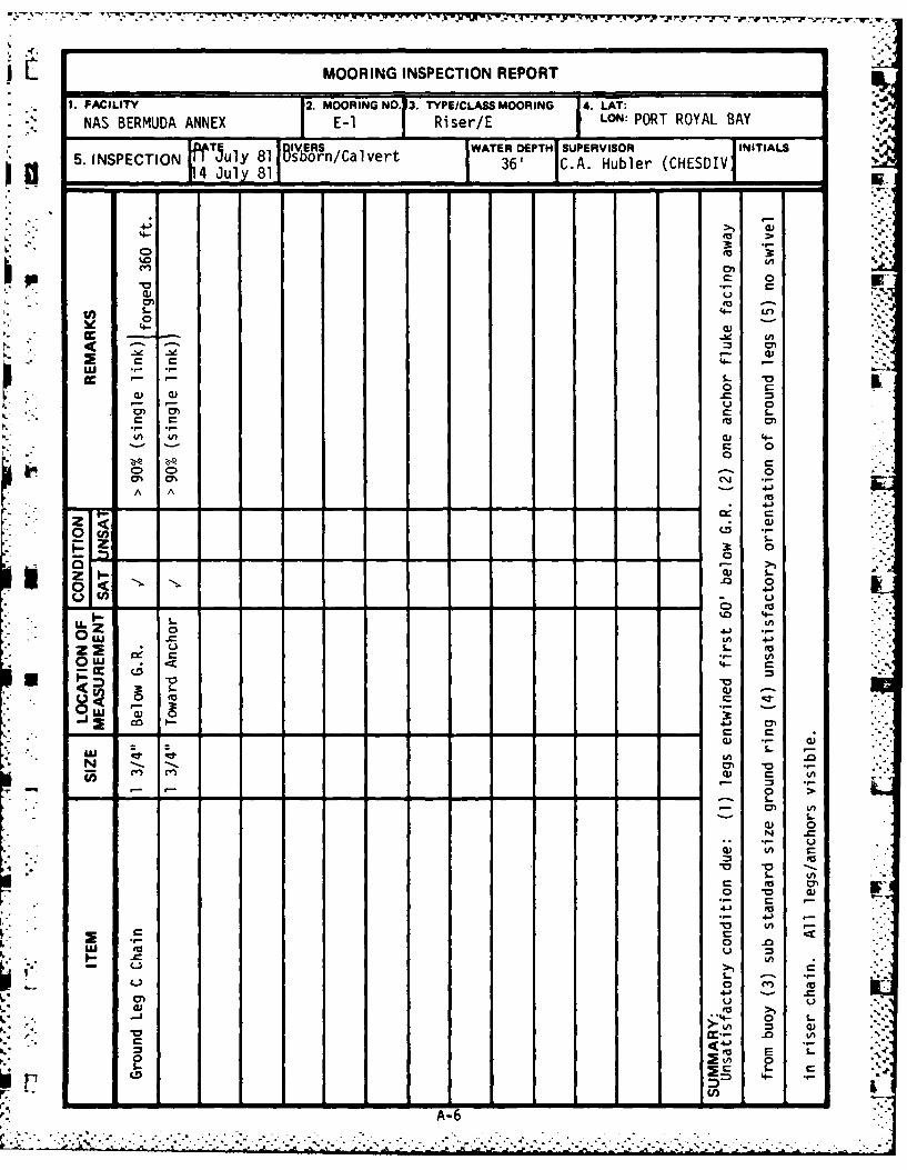
1.0 MOORING E-1 INSPECTION RESULTS.
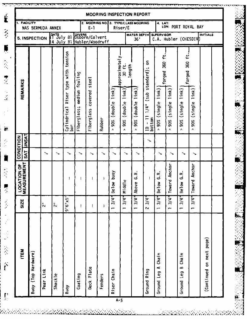
1.1 Findings. All components of this mooring installation were visible to
UCT-1 divers. The buoy was found to be in satisfactory condition, and
measurements of the wire diameter at three locations along the riser chain
proved to be better than 90% of the specified 1 3/4" size (DM-26). The only
shortfall in the riser assembly was the lack of a swivel.
The ground ring was located on the bottom (water depth 36') and was
determined to be of substandard size (14" outer diameter and 2 3/4" wire
diameter). The break load of a ground ring of this size does not meet DM-26
. specificatons and, therefore, this ring is unsatisfactory for use in a Class E
mooring. Each of the three legs consisted of approximately four shots (360')
of chain between the ground ring and anchor, and the sampled wire diameters of
each of these legs were satisfactory (> 90%).
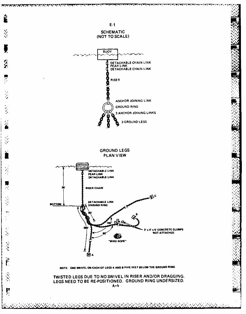
Although the material condition of the ground legs appear to be satis-
factory (> 90%), all three legs were intertwined for the first 60 feet from
* the ground ring, and below this point, all three legs were within a 1900
sector of the bottom (see Plan View, page A-I-2). Three 3' x 4' x 5'
unattached concrete clumps were located on the bottom between legs B and C, and
the anchor for leg B was observed to be backwards (the fluke pointing away
"- from the buoy). Assuming the mooring was correctly installed, it is probable
that it was moved under load and apparently dragged legs A and C across leg B.%A ...
A- 2
* - . -- -. 4 -. . . . . . .
1.2 ConclUsion/Recoriendation. This mooring is not safe to use and is,
p therefore, unsatisfactory for fleet utilization. Recommnend that the mooring
* be recovered, inspected, and overhauled as required.
A-3
E-1
SCHEMATIC(NOT TO SCALE)
P BUOY
DETACHABLE CHAIN LINK
PEAR LINKDETACHABLE CHAIN LINK
R S.RISER
ANCHOR JOINING LINK
GROUND RING
3 ANCHOR JOINING LINKS
3 GROUND LEGS
GROUND LEGSPLAN VIEW
DETACHABLE LINKPEAR LINKDETACHABLE LINK
36" RISER CHAIN
"." DETACHABLE LINKOTTO M GRO ND IN
NOT ATTACHED
" W O R E R O P E "
' '
5'A
NOTE: ONE SWIVEL ON EACH OF LEGS A AND 0 FIVE FEET BELOW THE GROUND RING
TWISTED LEGS DUE TO NO SWIVEL IN RISER AND/OR DRAGGING.LEGS NEED TO BE RE-POSITIONED. GROUND RING UNDERSIZED.
A-4
°.+P+,m* ° - .i , I , . I o , ,1 , i u F i l + le m o 4.1 I l 1 mm ° ¢ i °
S - - -,".' - ,- - "-,-.. I. - "-". - - ." -. . . ... . .. . . -:_. . -. . - . .
MOORING INSPECTION REPORT
1. FACILITY 2. MOORING NO. 3. TYPE/. LASS MOORING 4. LAT: Wk.
NAS BERMUDA ANNEX E-1 Riser/E LON: PORT ROYAL BAY
8 SWATER DPTI SUPERVISOR INITIALS
5. INSPECTION ATfuly S rn/Calvert 36' C.A. Hubler (CHESDI4 July 81 Hubler/Woodruff"- .
.4-o~4 Co. C.D....EE4- 4- -"
3: I-
cc 4) t
1) 0 0 0
4-) 40 ~ 0) a)
(ac~ to(A CA (A (
LIJ . - .. ., -.- - =E .-- . ,- .-
Q- 0) ;6- 'al ZL Z..m) C) C)C21C)C D C
• - m 4 0
"f. -0 L.- 4) A A A A A A AL9-
INK
4z 0:4:
- o> 0 0o "
- 3- -~L - O --,"- 0) ,-0 0
I.0L
CA
4) 0 0 V-{ "- 4) (I* 3 L (3 1.. "
*0 > 0 £E£- " 0" E".-40 )qJ O :.0 0 40"'0
-:: ., - ,.. , - - v " ",*, LU,. . . . .
Ni x
S - .- -
4-4)tmU
00
LU >) o ) 4 ):0- 3- *9 4)
33 .r
co co cm CD.S. . .j) L.
- 3.. Li 4J . ~ .0 . .0 A-5.
liii MOORING INSPECTION REPORT
1. FACILITY 2.MOORING NO.13. TYPEICLASS MOORING 4. LAT:
NAS BERMUDA ANNEX E-1 Riser/E LON: PORT ROYAL BAY
WATE DNPCIN 5l 16'~~s/avrEPTHJ SUPERVISOR INITIALS E
5 ~r INPCJO ,uly 811'~~/avr 36' C.A. Hubler (CHESDIVW
~fl -4 Juy 81 -Co
-r
W s- 4- >r
C 0
cm. 0)~ S.-
0 s.-
C> C- 0~E
471 -0 1
Au A.4
9- 9-c -
0 0) -LD
A A:
to4-
- 'F s- (o-
OEn
3u X
-~S.0
.0
- .
Z0 m
m0 L.
o O00 4- O
A-6
:.d4
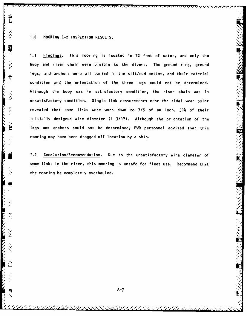
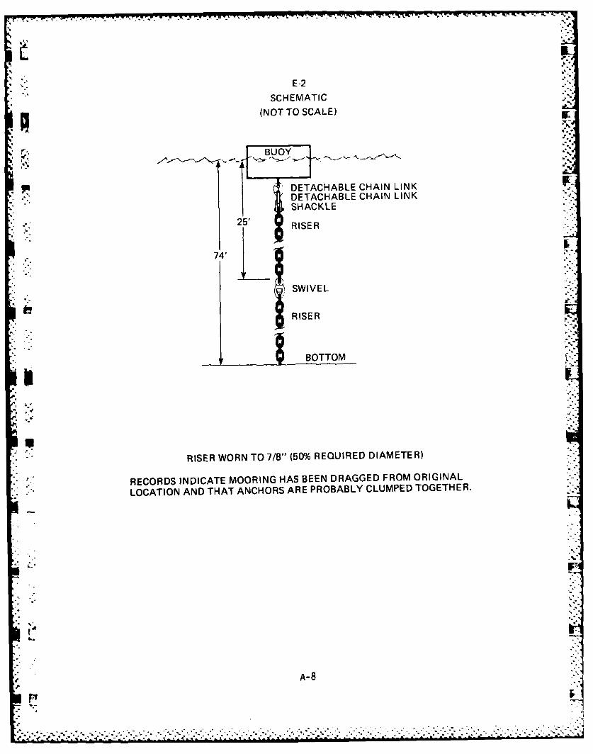
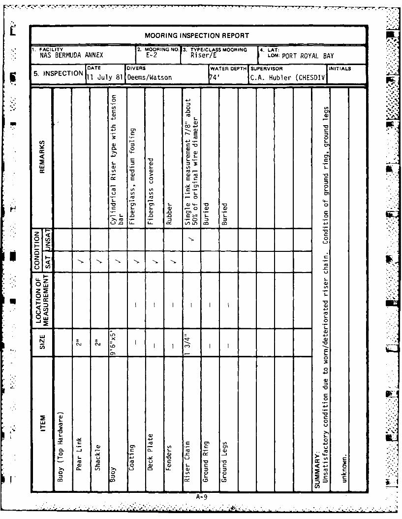
1.0 MOORING E-2 INSPECTION RESULTS.
. 1.1 Findings. This mooring is located in 72 feet of water, and only the
buoy and riser chain were visible to the divers. The ground ring, ground
legs, and anchors were all buried in the silt/mud bottom, and their material
• -condition and the orientation of the three legs could not be determined.
-- Although the buoy was in satisfactory condition, the riser chain was in
unsatisfactory condition. Single link measurements near the tidal wear point
" -- revealed that some links were worn down to 7/8 of an inch, 50% of their
initially designed wire diameter (1 3/4"). Although the orientation of the
legs and anchors could not be determined, PWD personnel advised that this
.. mooring may have been dragged off location by a ship.
1.2 Conclusion/Recommendation. Due to the unsatisfactory wire diameter of
some links in the riser, this mooring is unsafe for fleet use. Recommend that
. ." the mooring be completely overhauled.
I.A--
A-7-
•- -- -- -- - .*. . . . . ...- '-. . . .o
E-2SCHEMATIC
(NOT TO SCALE)
BUOY
UDETACHABLE CHAIN LINKI DETACHABLE CHAIN LINK
SHACKLE25' RISER
74'
-
SWIVEL
RISER
BOTTOM-
RISER WORN TO 7/8" (50% REQUIRED DIAMETER)
S"RECORDS INDICATE MOORING HAS BEEN DRAGGED FROM ORIGINAL
" "LOCATION AND THAT ANCHORS ARE PROBABLY CLUMPED TOGETHER.
A-8
.. . . . .
. . ..
. .~ . . . . . .. .
MOORING INSPECTION REPORT
1. FACILITY 2. MOORINGNO.13. TYPE/CLASSMOORING 4. LAT:NAS BERMUDA ANNEX E-2 Riser/E LON: PORT ROYAL BAY
DATE DIVERS WATER DEPTH SUPERVISOR INITIALS5. INSPECTION 11 July 81 Deems/Watson 4' C.A. Hubler (CHESDIV
CO4-
'"o .'- 9.":(A 0 U, )W *
C .04-4 - -
CL
• *. - 0 E -.• C--
>) EC4-) u S
0 ) > u(a-
E 0 0 c
t E( -A <-..- S. -"
-- . ra -0
•Sr- J .- 4- " " '
-,. o S. )- -o.-.:o". S..' 1. '-0° C -.0) Cn S- Q 4- -0 "-o---I- 1- ,-, a) (1)
- -0 -0 .0 r- - S-
C) :3L- -0 u- L-v o c -
0 Lu
o ,-
.
0 "
,,, Z:.-,"(C-
- S , ..- - 0- C
ow (A
*n 4-
* Ow S..- "
0
a -- - -. = -, _ - -.-
0 0
I I I"" '"" I I - ,-S4-
C ( a--
o0
uC
o 0 0S-- S
- o >1 c L
A-9 ,
S... " " " ' " " " " " ' ' ' ' -' - - . - ." ",", .'. ,-, ,' :
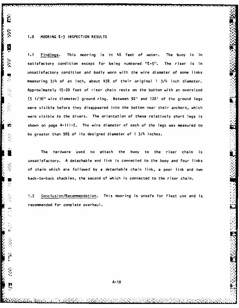
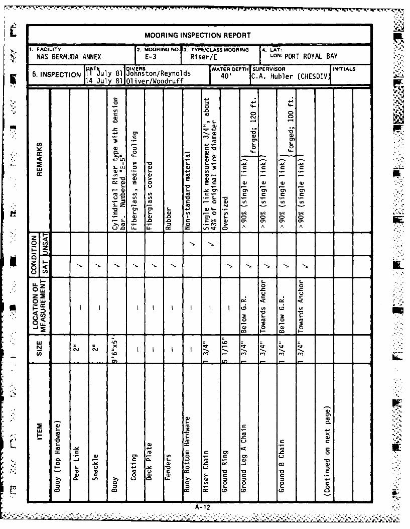
1.0 MOORING E-3 INSPECTION RESULTS
1.1 Findings. This mooring is in 40 feet of water. The buoy is in
satisfactory condition except for being numbered "E-5". The riser is in
unsatisfactory condition and badly worn with the wire diameter of some links
measuring 3/4 of an inch, about 43% of their original 1 3/4 inch diameter.
' Approximately 15-20 feet of riser chain rests on the bottom with an oversized
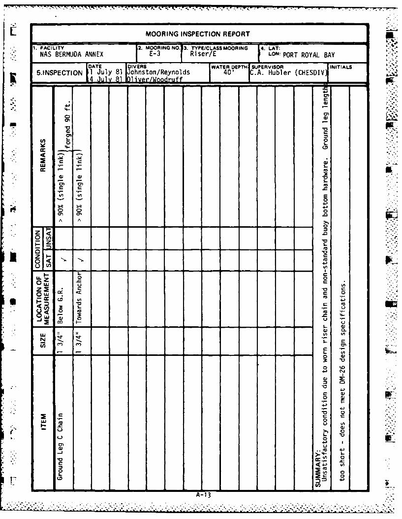
(5 1/16" wire diameter) ground ring. Between 90' and 120' of the ground legs
were visible before they disappeared into the bottom near their anchors, which
were visible to the divers. The orientation of these relatively short legs is
shown on page A-II-2. The wire diameter of each of the legs was measured to
be greater than 90% of its designed diameter of 1 3/4 inches.
The hardware used to attach the buoy to the riser chain is
unsatisfactory. A detachable end link is connected to the buoy and four links
S-, of chain which are followed by a detachable chain link, a pear link and two
1 back-to-back shackles, the second of which is connected to the riser chain.
-.-
- 1.2 Conclusion/Recommendation. This mooring is unsafe for fleet use and is
recommended for complete overhaul.
A-10
• " " "'2 ', ..' " , " .., ." -' " ...." ." ," ." :. .. .." ." .- " " . . ." .'. '. " .-',"". , .'.. .-'. - , . ,' -,• , -,- ',• -.' : -,' •.•
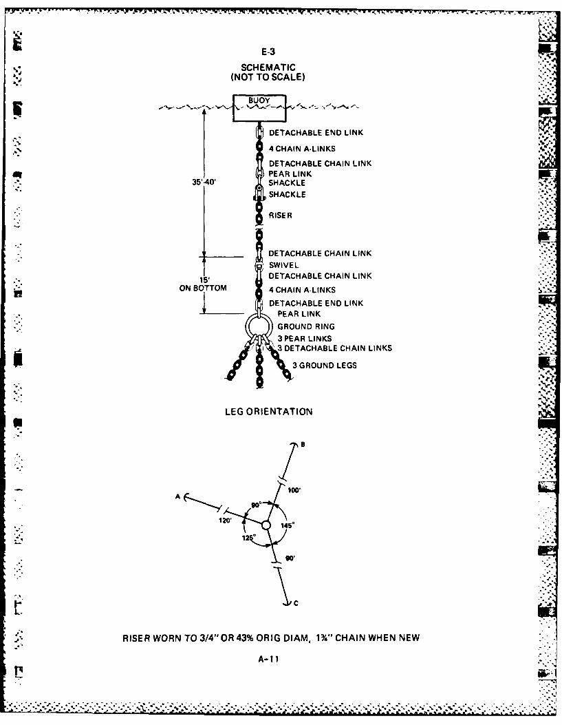
E-3
0, SCHEMATIC(NOT TO SCALE)
BUOY
DETACHABLE END LINK
I 4CHAIN A-LINKSDETACHABLE CHAIN LINK
J PEAR LIN35'-40' SHACKL
SHACKLE
R ISER
DETACHABLE CHAIN LINKSWIVEL
15' DETACHABLE CHAIN LINKON BOTTOM 4 CHAIN A-LINKS
DETACHABLE END LINK
PEAR LINKGROUND RING3 PEAR LINKS3 ~DETACHABLE CHAIN LINKS
3 GROUND LEGS
LEG ORIENTATION
100'
goo
RISER WORN TO 3/4"OR 43% ORIG DIAM, 1%" CHAIN WHEN NEW
A-11
0 ~ 7 ..
L MOORING INSPECTION REPORT
v 1. FACILITY ~2. MOORING NO.13. TYPE/CLASS MOORING 14. LAT:NAS BERMUDA ANNEX E3Ri ser/ELN:PRROABY
IIV WATER DEPTH I SUPERVISOR IINITIALS5. INSPECTION ulTy 81 WIVRsso/enls4' CA uer(HSI- 14 July 8110livper/Woqruf m .0 ~A ulr(HS
o 4-
:0
;;0 00. 0 4- 0 - 4
cc w3 C
4j, 0) 0
(- 1 ) > Ei0) 2- 00) 0 0) )
0 0 C -0 ) 4A CA (A 4)
- s- s-. 0) 4A . 0 fA, r A &o) Q) .0 I m~ L 0D C0 0 0~L .0 .0 0 = C, a) ON) a%) m~ 0
9- .- 0 -~ > A A A A(-).a LL. LL cz V/)~ 0t*C
RZ
0 0L
0 Uu
owo0 0 0 0
.0) 0 0) 0~ I- o
in %
4)00)'
00 4) 4)L
0 4A 4.) 0C= C 02 C 0) .C
~9- 0) ~ ' p U) 0 A -20) -
NAS BERMUDA ANNEX E-3 RsrELON: PORT ROYAL BAY
5.INSPECTION 1 Jl81 Johnston/Reynolds 40Q A. Hubler (CHESDIVJ
'4--
cn 0
o I-
0 .. . 1.C C a
* 10
A A-
0 <0.4-
0 u0
z U,
in 4J)
< o 0
8<2 3 .C 4-
IN
ru 0 '
m -u
to
S0
< 44) I
C.C
*0 0
- 4-)
A-13
1.0 MOORING E-4 INSPECTION RESULTS
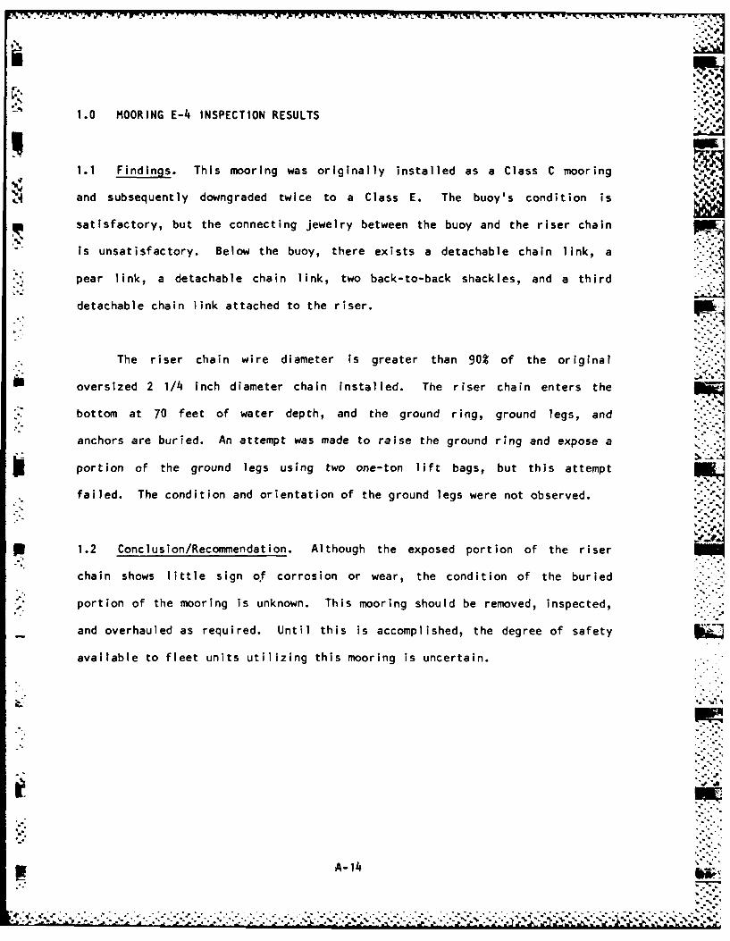
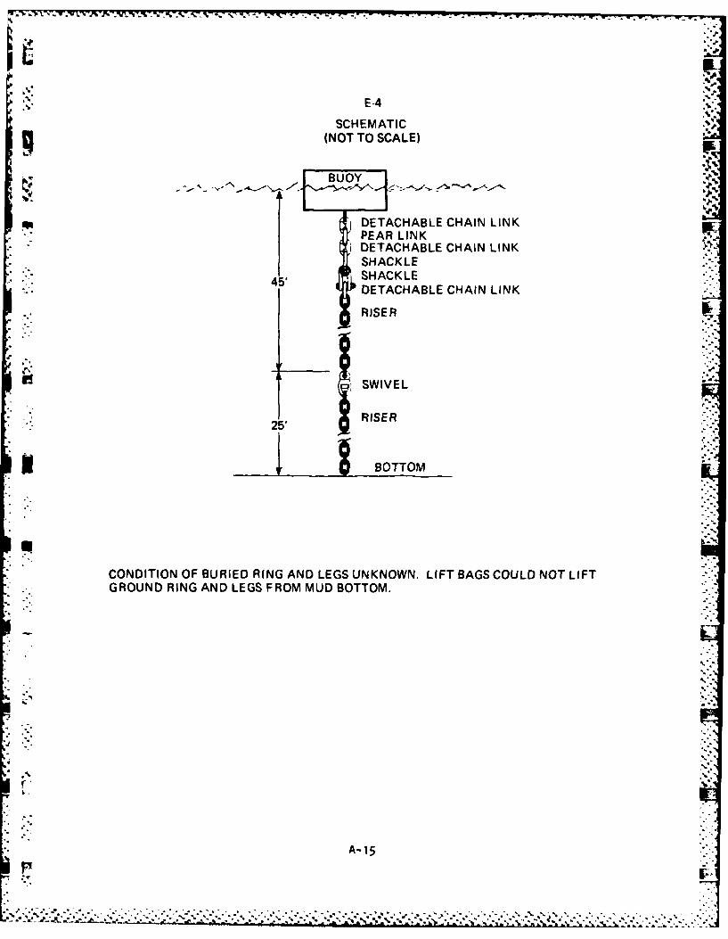
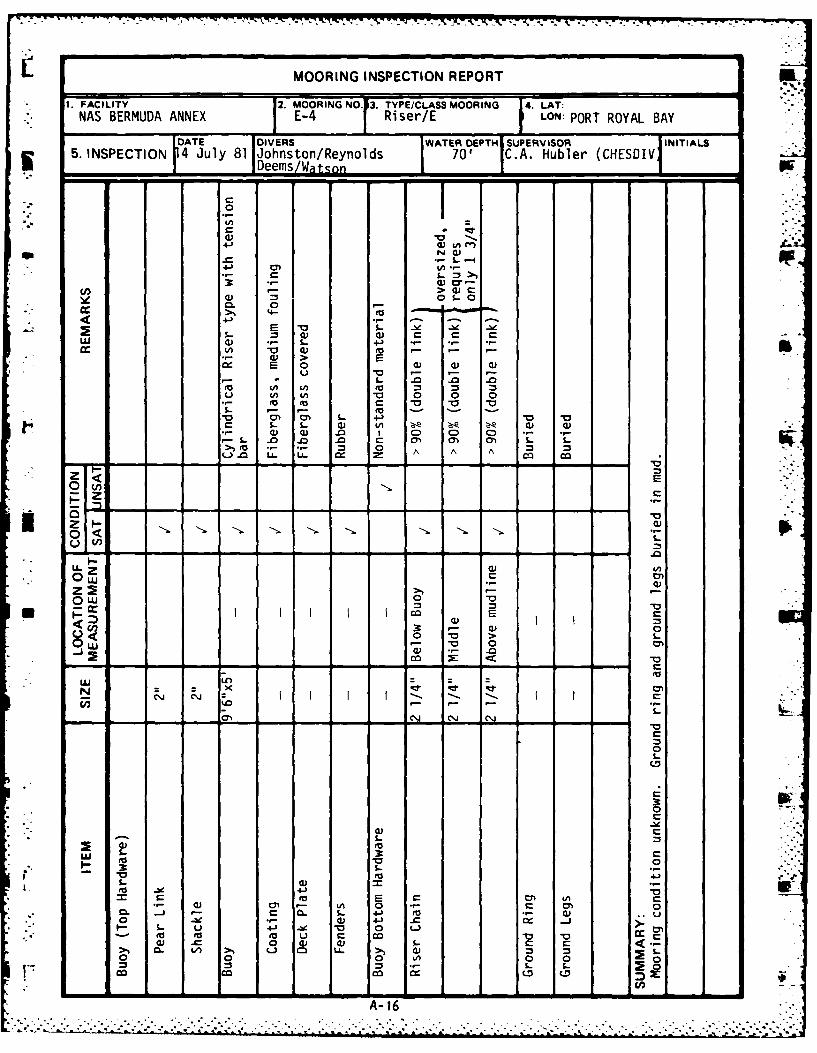
N1.1 Findings. This mooring was originally installed as a Class C mooring
and subsequently downgraded twice to a Class E. The buoy's condition is
satisfactory, but the connecting jewelry between the buoy and the riser chain
is unsatisfactory. Below the buoy, there exists a detachable chain link, a
pear link, a detachable chain link, two back-to-back shackles, and a third
detachable chain link attached to the riser.
The riser chain wire diameter is greater than 90% of the original joversized 2 1/4 inch diameter chain installed. The riser chain enters the
bottom at 70 feet of water depth, and the ground ring, ground legs, and
anchors are buried. An attempt was made to raise the ground ring and expose a
portion of the ground legs using two one-ton lift bags, but this attempt
failed. The condition and orientation of the ground legs were not observed.
1.2 Conclusion/Recommendation. Although the exposed portion of the riser
chain shows little sign of corrosion or wear, the condition of the buried
1 . portion of the mooring is unknown. This mooring should be removed, inspected,
and overhauled as required. Until this is accomplished, the degree of safety
available to fleet units utilizing this mooring is uncertain.
MI
A-14.
E-4
SCHEMATICq (NOT TO SCALE)
BUOY
* DETACHABLE CHAIN LINKPEAR LINK
I DETACHABLE CHAIN LINKI SHACKLE45* SHACKLE
DETACHABLE CHAIN LINK
RISER
SWIVEL
RISER
__ BOTTOM
CONDITION OF BURIED RING AND LEGS UNKNOWN. LIFT BAGS COULD NOT LIFT* GROUND RING AND LEGS FROM MUD BOTTOM.
A- 15
.7 K -7 .-
MOORING INSPECTION REPORT
. FACILITY .MOORINGNO. 3TYPE/CLASS MOORING 14. LAT:NAS BERMUDA ANNEX E-4 Riser/E LON: PORT ROYAL BAY
DATE DIVERS WATER DEPTH SUPERVISOR INITIALS5. INSPECTION 4 July 81 Johnston/Reynolds 70' C.A. Hubler (CHESDIVIDeems/Watsonl ri
0C I-- (V 0" n
4J L
rrX (1) r --
>a)
4.) - .. ' .- -. - -
'I." ° 0 - - '
~~ o , .
4),> E
E 0A "a 0 0 0
"o-o -
-. ,- -~ .0 .--i (V .0 ) 0 ) 0 C0
S- -. - 0 m - m..-
C S.- 5- 0 ,.- .,- ,.)-0-
>Ic .- o A A A
S 0 ,-"LLzV
zE0. <
"L- z1 Q) (Au' "
.' .
0 L-u ' .
co E
0 > "Ow 0 0
- a•) o ill I
0A VV >cc 00
0
N -
tto - 1S--
00
0 C)>1-
0 V A 03o S.
rL I I 0 4-I5-A-16
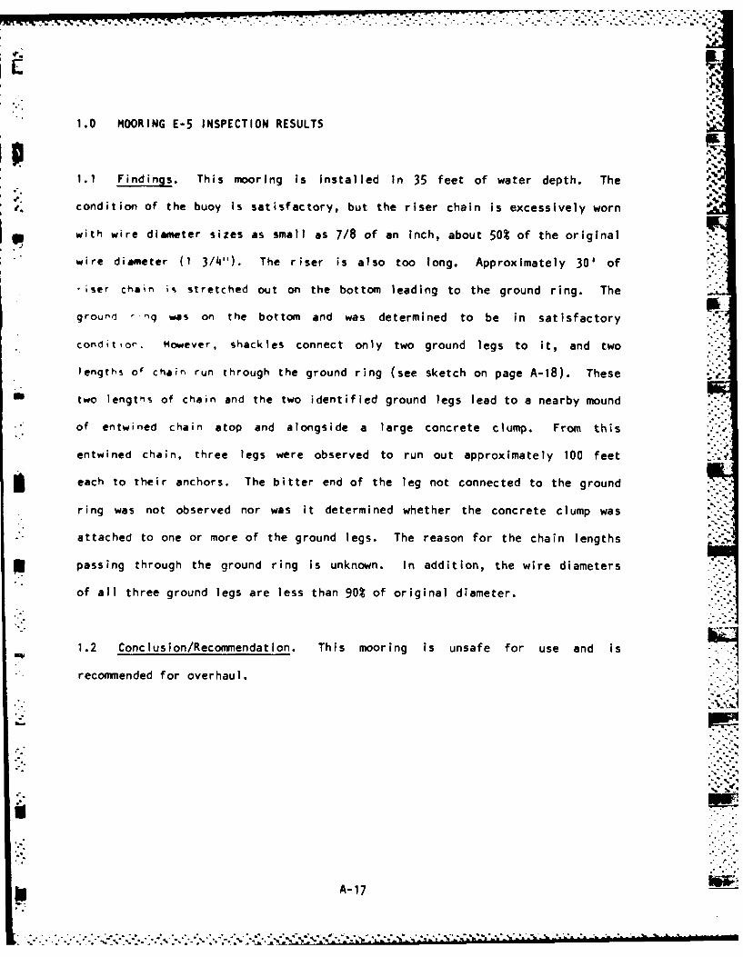
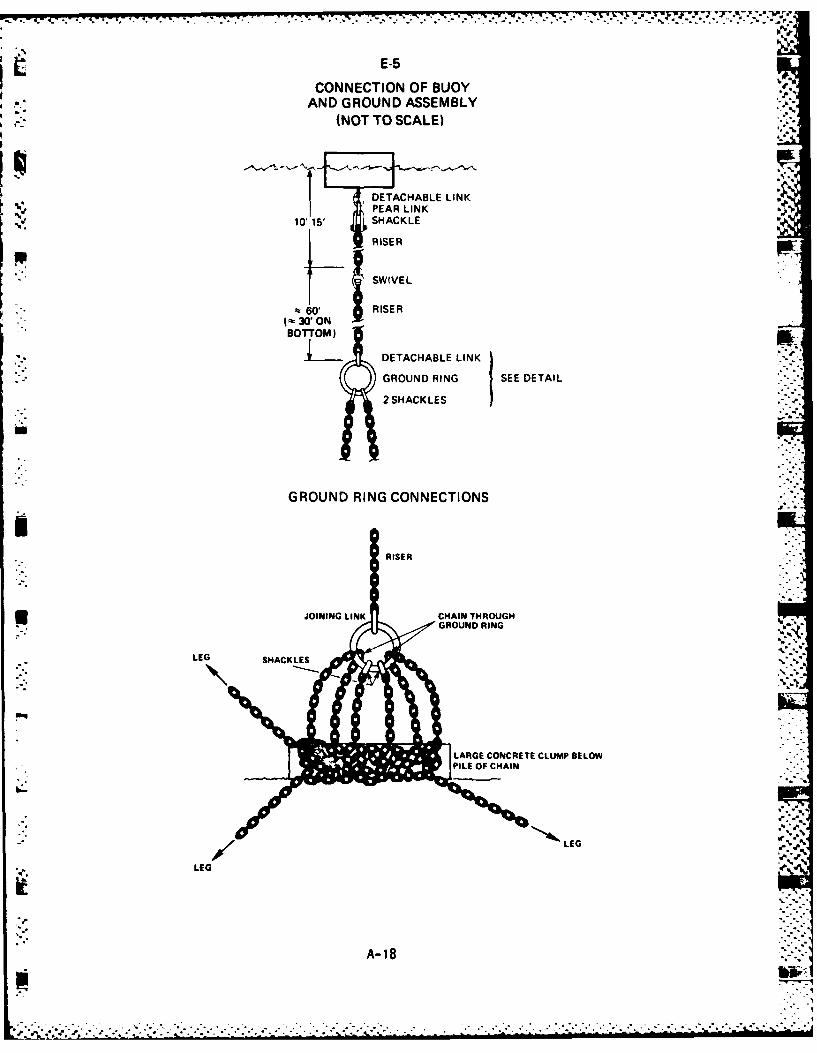
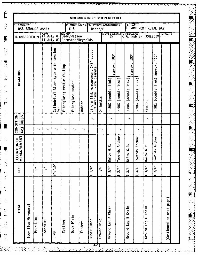
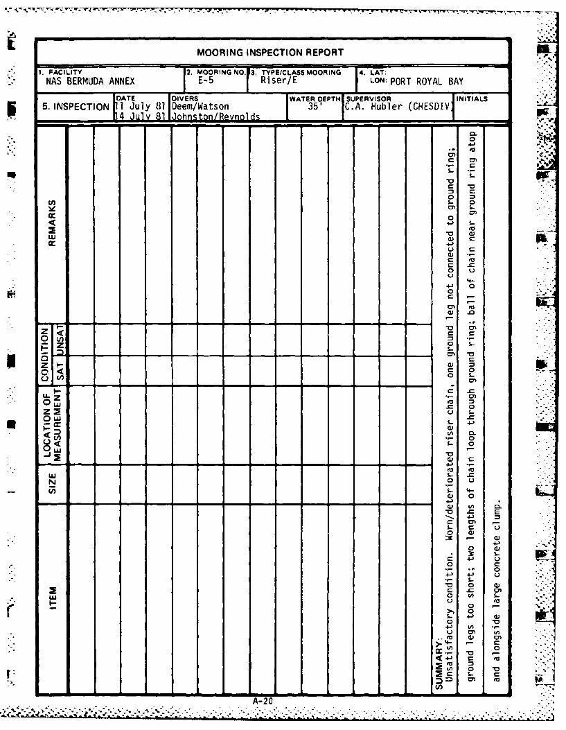
1.0 MOORING E-5 INSPECTION RESULTS
1.1 Findings. This mooring is installed in 35 feet of water depth. The
condition of the buoy is satisfactory, but the riser chain is excessively worn
with wire diameter sizes as small as 7/8 of an inch, about 50% of the original
wire diameter (1 3/4"). The riser is also too long. Approximately 30' of
iser chain is stretched out on the bottom leading to the ground ring. The
ground -q was on the bottom and was determined to be in satisfactory
condit ior. However, shackles connect only two ground legs to it, and two
lengths of chain run through the ground ring (see sketch on page A-18). These
two lengths of chain and the two identified ground legs lead to a nearby mound
of entwined chain atop and alongside a large concrete clump. From this
entwined chain, three legs were observed to run out approximately 100 feet
each to their anchors. The bitter end of the leg not connected to the ground
ring was not observed nor was it determined whether the concrete clump was
attached to one or more of the ground legs. The reason for the chain lengths
passing through the ground ring is unknown. In addition, the wire diameters
of all three ground legs are less than 90% of original diameter.
1.2 Conclusion/Recommendation. This mooring is unsafe for use and is
recommended for overhaul.
A-1 7
,. . . . .. .. ......
E-5
CONNECTION OF BUOYAND GROUND ASSEMBLY
(NOT TO SCALE)
I ,DETACHABLE LINKPEAR LINK
N'101-15' SHACKLE
RISER
~SWIVE L
~60, RISERW~3'ON I
BOTTOM) DETACHABLE LINK ~SEDTI
2SHACKLES
GROUND RING CONNECTIONS
RISER
JOINING LINK CHAIN THROUGHGROUND RING
LEG SHACKLES
LARGE CONCRETE CLUMP BELOW
LLEG
A- 18
L MOORING INSPECTION REPORT
1. FACILITY 12. MOORING NO.13. TYPE/CLASS MOORING 14. LAT.
NAS BERMUDA ANNEX E-5 IRi ser/E LON: PORT ROYAL BAY
5.INSPECTION l ~uy 81l N Wts on AT~PT P/Rfer (CHESDIV IIIL
114 July 81jJohns ton! -1.L.......... .- - .-
oc0 x
00 0 0
(n34-3 &- L. %.-4- () 06 0.L0
r-E 0L 0L 0.cc0 0 wo 0 (0
> -
tn 4-' .-3..- 0 0)c
0 0 IA
I A, 5 0 0 0 0 0cm 0 0 0. -o -0 o-
- - 41 - -
S- ~~~ S-o0 - "Q Z
.0 CD C) C) C> C)
C) r- A1A...- 0z 0) 0r 0)D
Z F-
0 L~0
0 * w w- cc .
o 0 0 0
(1) 0 (1 0 ) C
*cm F- c -
N 0 l- 2<~.. j0
mn -mn - - -
A- r- 0Q) cm *..t .:. -m-
MOORING INSPECTION REPORT
1. FACILITY 2. MOORING NO. 3. TYPE/CLASS MOORING 4. LAT:NAS BERMUDA ANNEX E-5 Riser/E LON: PORT ROYAL BAY
DATE DIVERS WATER DEPTH SUPERVISOR INITIALS5. INSPECTION I July 81 Dem/Watson 35 C.A. Hubler (CHESDIV
s- 0
cr 0
U r-
o U
4-
4- 0)
0
z~ 0 s
S4-
0 L0
L'3 04
1-
.- 4-)(1 0
-~ 0
4-)
,al 0.
0
0
4-
C 0)
A-20.
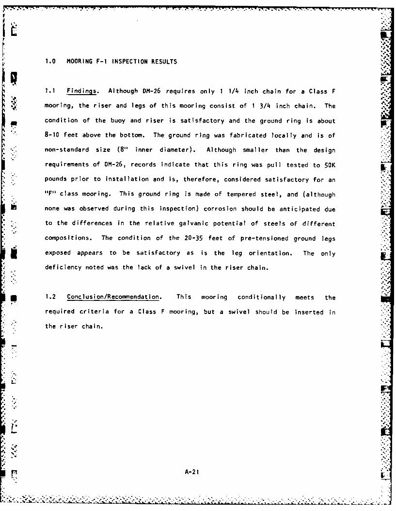
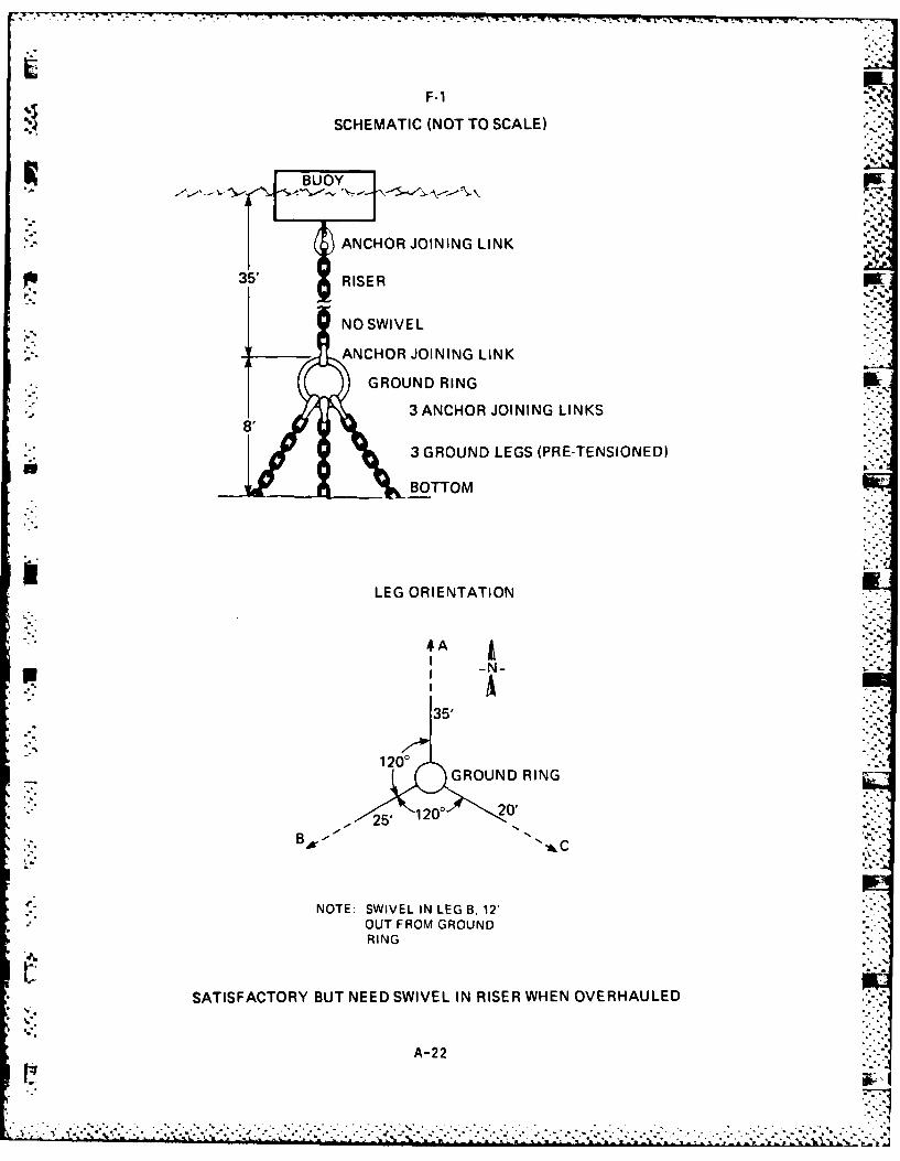
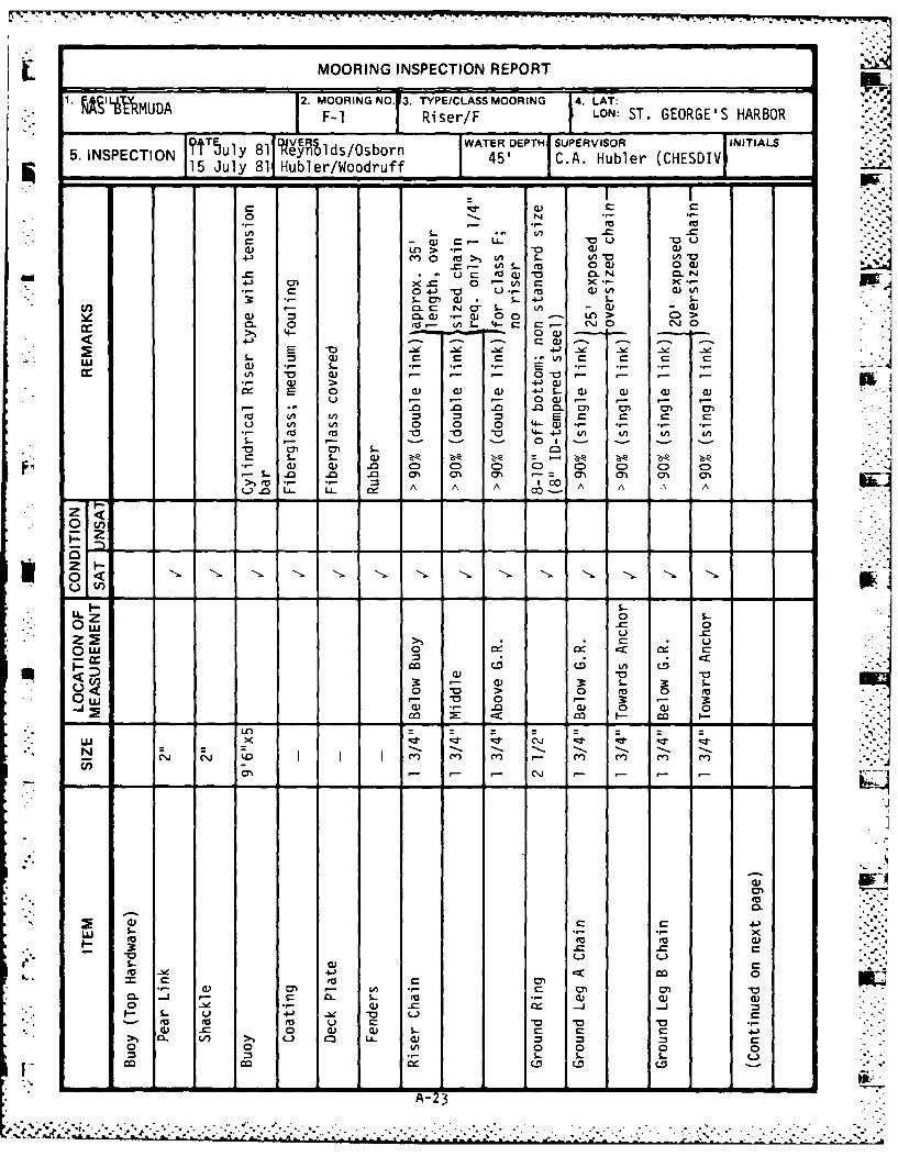
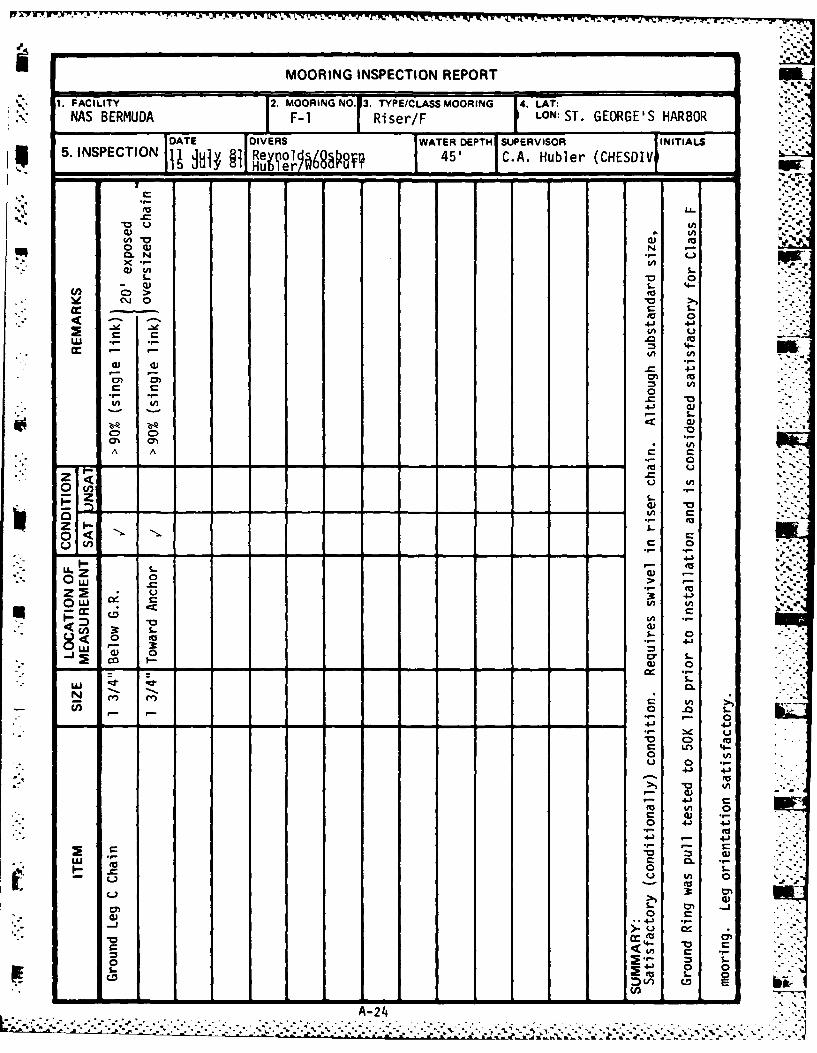
IL1.0 MOORING F-1 INSPECTION RESULTS
1.1 Findings. Although DM-26 requires only 1 1/4 inch chain for a Class F
mooring, the riser and legs of this mooring consist of 1 3/4 inch chain. The
- condition of the buoy and riser is satisfactory and the ground ring is about
8-10 feet above the bottom. The ground ring was fabricated locally and is of
non-standard size (8" inner diameter). Although smaller than the design
requirements of DM-26, records indicate that this ring was pull tested to 50K
pounds prior to installation and is, therefore, considered satisfactory for an
"F" class mooring. This ground ring is made of tempered steel, and (although
none was observed during this inspection) corrosion should be anticipated due
, - to the differences in the relative galvanic potential of steels of different
compositions. The condition of the 20-35 feet of pre-tensioned ground legs
exposed appears to be satisfactory as is the leg orientation. The only
- deficiency noted was the lack of a swivel in the riser chain.
! 1.2 Conclusion/Recommendation. This mooring conditionally meets the
required criteria for a Class F mooring, but a swivel should be inserted in
the riser chain.
F, A-2 1
-........... .... .
. . . .. . . . . . . . . . . . . . .. . . . .
-.... .. .. .. .. .. . .. .. .. .. .. .
F-1
SCHEMATIC (NOT TO SCALE)
BUOY
T N 1 ANCHOR JOINING LINK
35 ' RISER
NO SWIVELANCHOR JOINING LINK
GROUND RING
3 ANCHOR JOINING LINKS8'
3 GROUND LEGS (PRE-TENSIONED)
BOTTOM
LEG ORIENTATION
I -N-
35'
1200GROUND RING
- 2' 1200 20'-- B,, "Ao - ' ,.,o . -C. .
NOTE: SWIVEL IN LEG B, 12'OUT FROM GROUNDRING
SATISFACTORY BUT NEED SWIVEL IN RISER WHEN OVERHAULED -
A-22
MOORING INSPECTION REPORT
1. FILTYMUDA 2. MOORINGNO. 3. TYPE/CLASS MOORING 4. LAT:'- Riser/F LON: ST. GEORGE'S HARBOR
5 ~ ~ ?~~ INPCTO luy 1 g~1S/Ob WATER DEPTHI SUPERVISOR INITIALS5. INSPECTION 1 uly 81 uer/Oor 45' C.A. Hubler (CHESDIV45 C. . aule . - . -
115 July 81IHubler/W°°d'ruff i !
o N
a) r- LL. a uC-
C w C t- rLA. Qj L).) L>-'-4) m 0 ro> tn S. (A0 Io(A
-c in S.. 0 a) 0-4,u. aJ to4 cl -0 C.N M.N
4-) U) C- 0 r l CC ~04-'0 CU-E 4E i
id CL :3 i .cu c o o > CD>, 4- u..Ef - 4. N0 J.,n-4
of E 0 cu un 1 4- .- 0) , , C Q
u. C) 0 Q
4. - - 4-"- C4 - A 0 (A2.,. l- L0 1 -A ^ C '"
cu Q) CD C CDi C= C C CD
u- 0 L- Cc
,-, , ,- ,- 0 0 . . .0
• <0 <•- . 0 0-. . A ' C. --0~ O
tn
U..z 0 S-.0 .CJ 0
0. in (0 c
* < ") J -"a-c o - ) 3 : s- -<w .2 > 0 (a E
0 0 - 0 0 -4, a) - -0 Q) 0 a) 0
- 1 -.--"- -
.I - MI .
cuu
in c- s-(1ou cu Eu- 4
cu 0.. a) C
0 . 0, Ln .- in 0r C0~
-~s Eu EuE U C04o C o 0c (D 4, 1Lo
* >~ . CA >, L) C U A-23
MOORING INSPECTION REPORT
1. FACILITY 2. TYPE/CLASS MOORING 4. LAT:
AS BERMUDA MOOING N *Ri ser/F FLON: ST. GEORGE'S HARBORDATE iDIVERS WATER DEPTH SUPERVISOR INITIALS5. INSPECTION Re 45' C.A. Hubler (CHESDIVI"
m . ',.
Li.. - -
0 ) No N
4))
01 0
~0
0 > .p >9z - 0 0
CD t .,_
£).
9- U -U)
- - -o ._..-:
00
.9-, ,U,4--
S2" 4-- A- ALA C
< o~
cc . a) -
-- -l
8<~t 0 U- -00 4.)
3 - 4J
Q)
4- 0 0.-9.- to
N ,.,In
- cn 0 -A-24
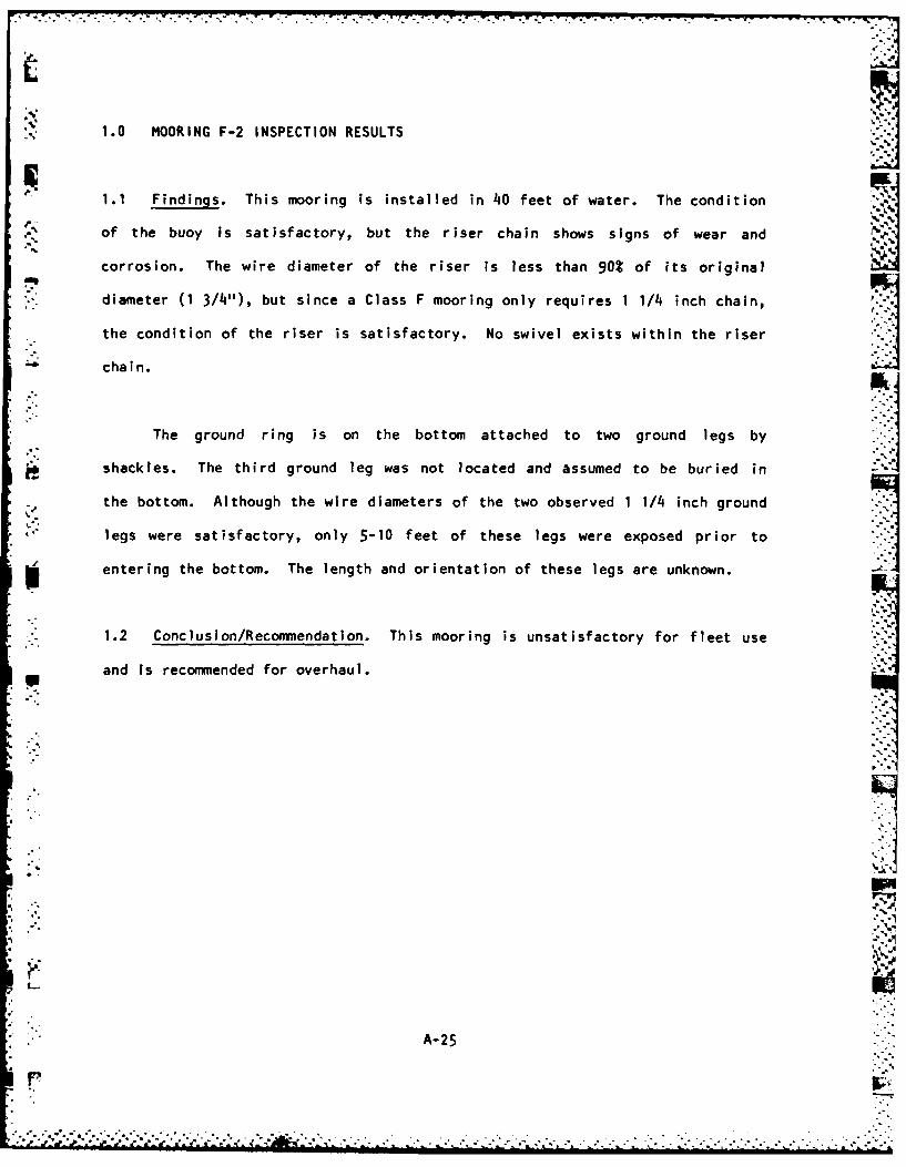
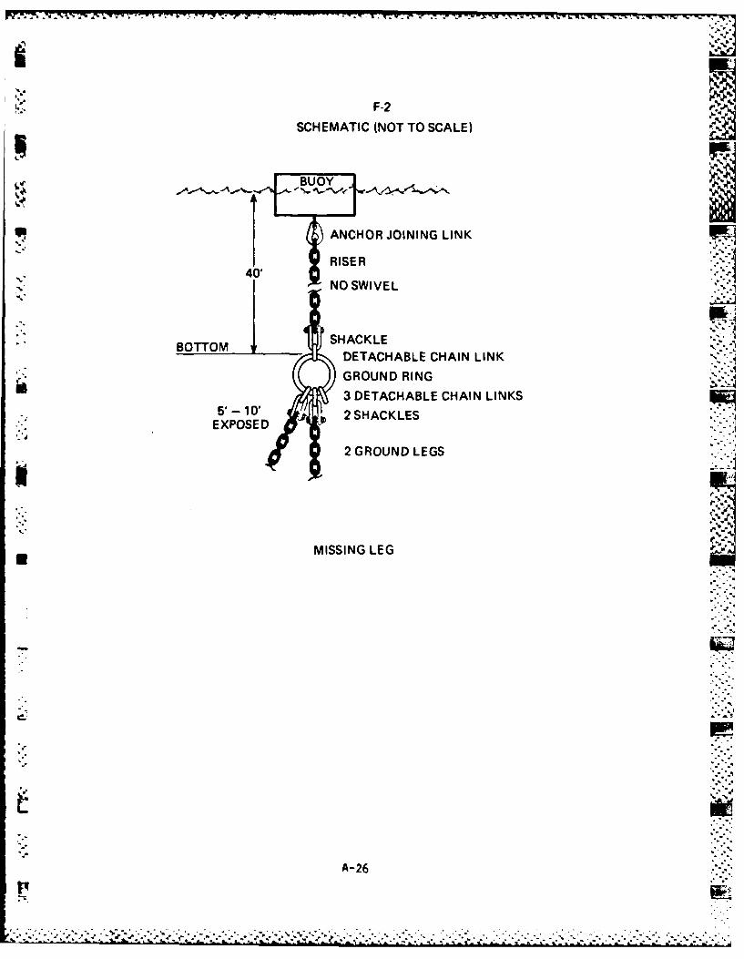
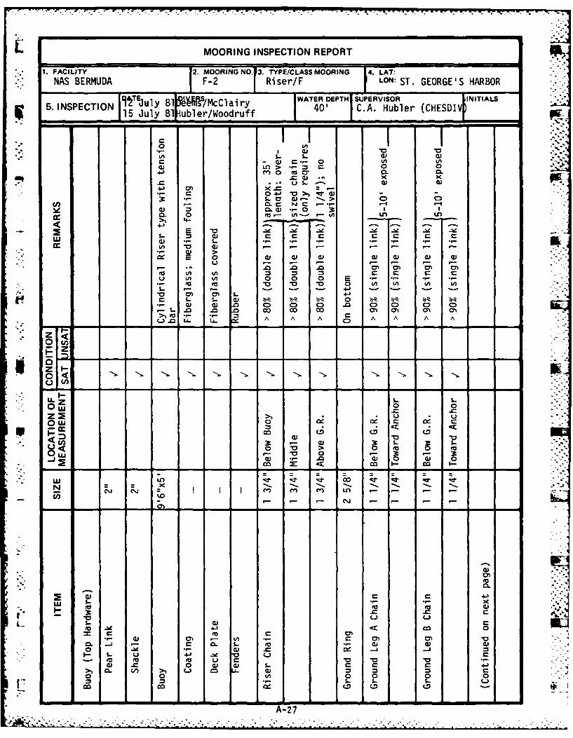
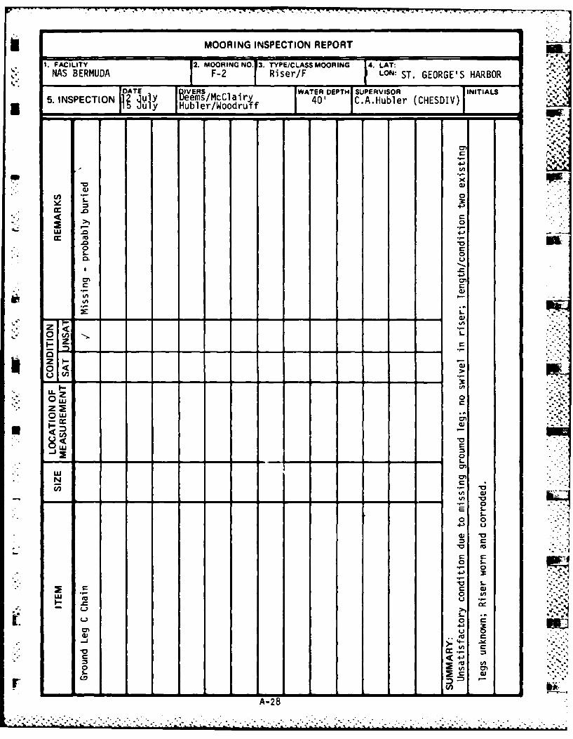
1.0 MOORING F-2 INSPECTION RESULTS
1.1 Findings. This mooring is installed in 40 feet of water. The condition
of the buoy is satisfactory, but the riser chain shows signs of wear and jcorrosion. The wire diameter of the riser is less than 90% of its original
diameter (1 3/4"), but since a Class F mooring only requires 1 1/4 inch chain,
the condition of the riser is satisfactory. No swivel exists within the riser
chain.
The ground ring is on the bottom attached to two ground legs by
shackles. The third ground leg was not located and assumed to be buried in
the bottom. Although the wire diameters of the two observed 1 1/4 inch ground
legs were satisfactory, only 5-10 feet of these legs were exposed prior to
entering the bottom. The length and orientation of these legs are unknown. -
1.2 Conclusion/Recommendation. This mooring is unsatisfactory for fleet use
and is recommended for overhaul.
A--25
* . .4
'-" F-2
SCHEMATIC (NOT TO SCALE)
BUOY
" UDANCHOR JOINING LINK
RISER
40' iBOTTOM SHACKL
DETACHABLE CHAIN LINK
" ( GROUND RING3 DETACHABLE CHAIN LINKS
5'-O2 2SHACKLES
4 EXPOSED
2 GROUND LEGS
MISSING LEG
A-26
"'.° * .'-.-.-
-.-. . . . . . . . . . . . . -.
MOORING INSPECTION REPORT
1. FACILITY 2. MOORING NO. 3. TYPE/CLASS MOORING 141. LAT:NAS BERMUDA F-2 Riser/F LON: ST. GEORGE'S HARBOR
WATER DEPTH SUPERVISOR INITIALS5. INSPECTION 15 July 81 ubler/Woodruff 40' C.A. Huble
• , s. -,.
.rr 0
Cn > I C
. 4)
4-) - >- 0 )
) LA> r- N C 00) C0))
CL~ 0 LA. 'A
3 s-
0 . N . - - .-I -
3a I
in - _ -_ k
,-o 4) " 0 tA CA C
•In ( 4) e.- e- - 1"-"
.- -1 > - - - -
-. &- - 0- -" - .-
- *. 0 .0 0 00 00 (7) m l 01
o V In o In In "
S..: ., - .) -, -
U. - L.A A AA A A A
0<
A--
0w0
LL. Z s- s-
Ow 0U o
) -o >0 0 0 t0w 0 -3 . 3
_4 ) .g) 004 0
-ejcc X': < L o co
04- ' - -v Lc
Qj 4J
wU S.- x~4 04
S. 4)-n In . 0
o Q) .* ~ - S.. U 41 ~
a) .C0 4) 4D L- c C- C 4> C 0 V) U. im 0 - 0)C
O n0 0 0
Co. O D C.D LD
A-27
MOORING INSPECTION REPORT__
1. FACILITY 2.MOORING NO. 3. TYPE/C LASS MOORING 14. LAT:J,HAS BERMUDA F-2 Riser/F LON: ST. GEORGE'S HARBOR
lf~l R~eI/Mca WATER DEPTHl SUPERVISOR INITIALS5. INSPECTION l Her/odrf 40' C.A.Hubler (CHESDIV)
nin HubUer/oodruf
00
%- 0
0.
L))
z 0
0<0
0K --
09 *I. Q)
A-28
* . . .- o
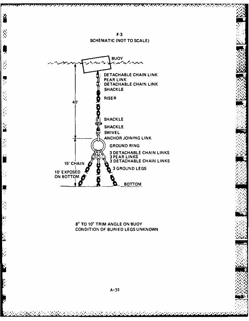
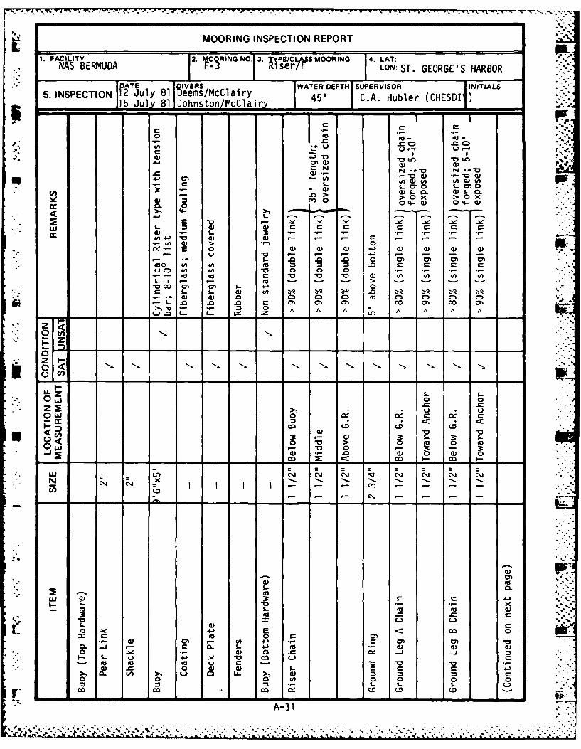
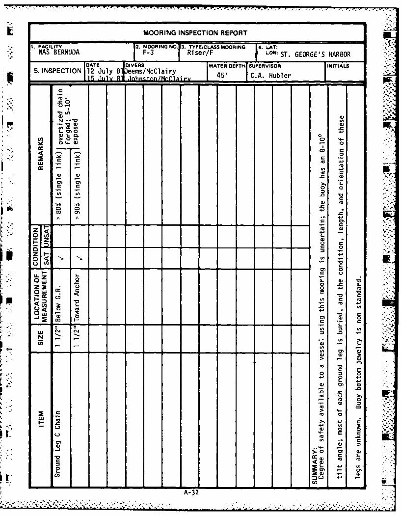
-" 1.0 MOORING F-3 INSPECTION RESULTS ..
1.1 Findings. This mooring is in 45 feet of water and was initially
installed using 1 1/2 inch chain in the riser and its three legs. Although
the exterior condition of the buoy appears satisfactory, its internal
integrity is questionable since the buoy has an 8-10 degree trim angle. The
condition of the bottom jewelry is non standard, but the condition of the
pp riser appears to be satisfactory. The ground ring is about five feet above
the bottom, and about 10-15 feet of each of the three ground legs attached to
* it are piled on the sea floor beneath it. The wire diameter of each of the
three legs measure less than 90%, but greater than 80%, of its original 1 1/2
inch diameter. The remainder of each of the legs are buried and their lengths
and orientation are unknown.
1.2 Conclusion/Recommendation. From a safety standpoint, the use of this
mooring by fleet units is questionable, The mooring should be removed, the
buoy should be thoroughly inspected in order to determine the cause of its
Plist, and the condition of the ground legs should be determined. The mooring
should be overhauled as required prior to reinstallation.
-7
' ' ~A-29 "-"
........................................ ".... *. .2.."-... . 'i.~~~~~~~..........................-.............................. ,.-. -. - -, ..........-.. _'',_
F-3
SCHEMATIC (NOT TO SCALE)
BUOY
DETACHABLE CHAIN LINKPEAR LINK
SDETACHABLE CHAIN LINKSHACKLE
RISER40'
SHACKLE
SHACKLESWIVELANCHOR JOINING LINK
GROUND RING
3 DETACHABLE CHAIN LINKS3 PEAR LINKS
15' HAIN3 DETACHABLE CHAIN LINKS3 GROUND LEGS
10' EXPOSEDON BOTTOM
BOTTOM
80 TO 100 TRIM ANGLE ON BUOYCONDITION OF BURIED LEGS UNKNOWN -
A-30 '
MOORING INSPECTION REPORT
1. FACILITY 2. IOQRINGNO. 3. PE/C S MOORING 4. LAT:NAS BERMUDA Riser/l- LON:ST. GEORGE'S HARBOR
DATE DIVERS WATER DEPTH SUPERVISOR INITIALS
5. INSPECTION 12 July 81 Weems/McClairy 45' C.A. Hubler (CHESDI )15 July 81Johnston/McClairz -
L0-C C
>' o x >010 0- w 0-W
- Qe U4 -
.. *c .C ,- U - 'a) 4.)* ". Ig".
>1 a ) a4) .r-N --. T N -*.(
40
w, S- 3:a) (1 04a) 0%a
" E 0 1) a.) a) 4)ao *. L. 3 .- .- .- .- .- .r *.-
-. 0 a) a - - E - (M "- I..*L) C ) (A 0
to to 0 a a ^ ) a a ^ A.- ..- --> --
0. . .. .0 . . 0 - ) 0. ) .. .00) C" 0o C C" C C
c0 al ON 0 01 00 04M-to 0 0 A A a) A, An A A-0 g - L-0 -
0C0.,- ,', L. o.) 0
.-. ) ) 0 0- 0 0
-- A A
L). Li. LA.0A
'* 2
0 0j
co CD cz 4
o 0 0 to Co
W0-0- 3 - 3 = 0 -Sa) -. 0 a1) 0 a) 0
I o < o-o
N -x
- 3 -"-- - - -- - -. ,- - -.
a) 0
-S 0
S. 0
L. C)-h a ur
to (a -o U , 4. r-C 0
0 0 0a) a)a. C CD C(D
A-31 A.
MOORING INSPECTION REPORT
1. FACILITY 2. MOORING NO. 3. TYPE/CLASS MOORING 4. LAT:NAS BERMUDA F-3 Riser/F LON: ST. GEORGE'S HARBOR
DATE DIVERS WATER DEPTH SUPERVISOR INITIALS
5. INSPECTION 12 July 81 eems/McClairy 45' C.A. HublerIr l ,iilv Al ,lnhn,,tnn/Mr-rlairv
"IiiuI'E- U n.,ur .--- ,
- .9 T - -- --- -
O -4 . .- "-.:
A (1)"LA
. ,. ..-
• " i 1" 0,,
a) s- CL 0 '
4-)
-- , - -,, 0
In 4
a C0
-- .- C
o 0,.4- *3
0 4m"
' "" ,r- o =
:i i-
0-C
,- 1> a, ''0 ,o)
0O = E0n C
0 0 - I
3 4-
I:" m" c "..- "
) 0)
* - , ,- - . . . ° - 1 - -' ' ' ' , .'
V - >
C.., ~ ' I ~ E
> 4-
4- E a
L o 7-0
>. 0 -c St)
0.
A-32
T7 W. 17 V. K 7 7- .7 t" 7 -7 7. -7 7-
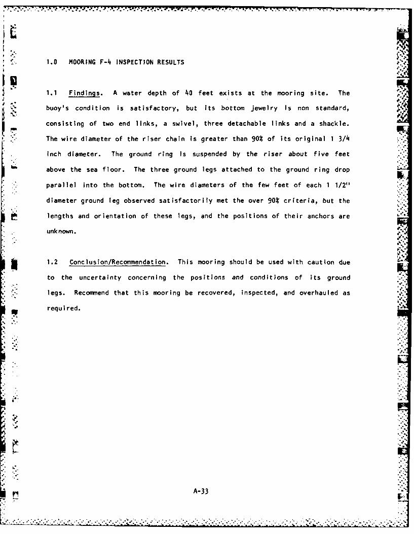
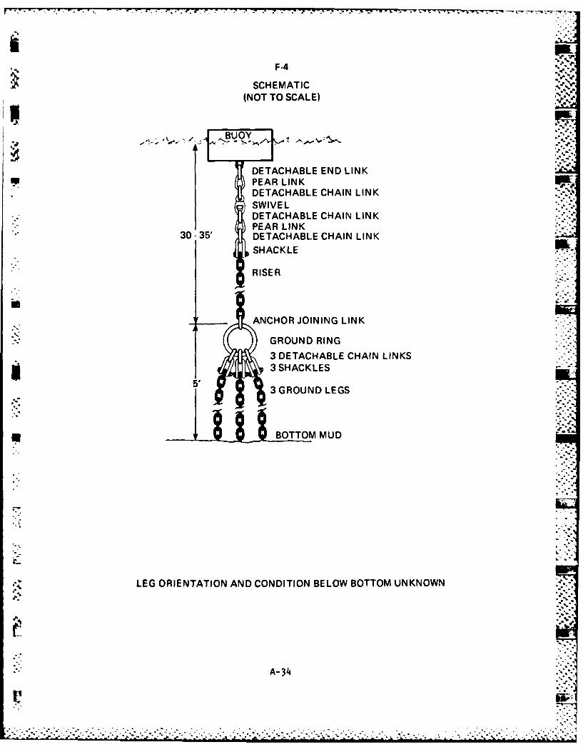
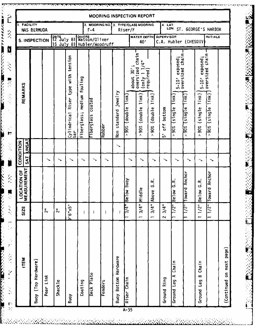
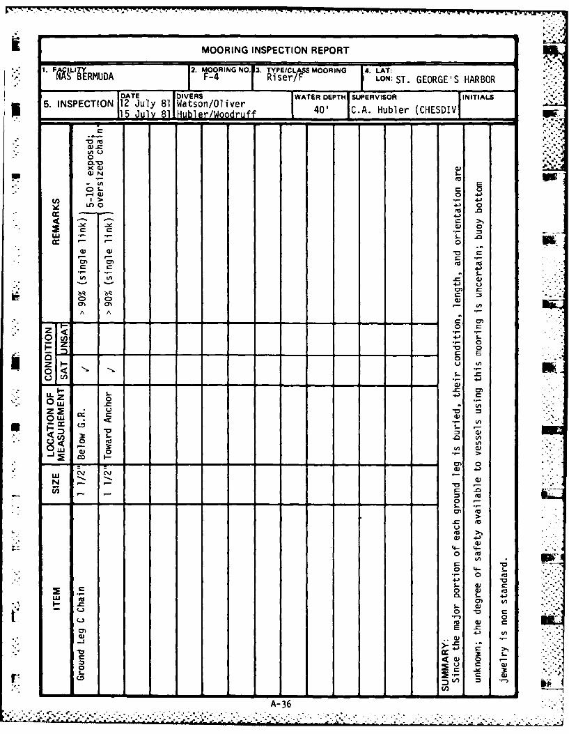
1.0 MOORING F-4 INSPECTION RESULTS
1.1 Findings. A water depth of 40 feet exists at the mooring site. The
buoy's condition is satisfactory, but its bottom jewelry is non standard,
consisting of two end links, a swivel, three detachable links and a shackle.
The wire diameter of the riser chain is greater than 90% of its original 1 3/4
inch diameter. The ground ring is suspended by the riser about five feet
above the sea floor. The three ground legs attached to the ground ring drop
parallel into the bottom. The wire diameters of the few feet of each 1 1/2"
diameter ground leg observed satisfactorily met the over 90% criteria, but the
lengths and orientation of these legs, and the positions of their anchors are
unknown. r
m 1.2 Conclusion/Recommendation. This mooring should be used with caution due
to the uncertainty concerning the positions and conditions of its ground
legs. Recommend that this mooring be recovered, inspected, and overhauled as
required.
A-339-. ,- .- .. -. .. - . .5
. . . .. . . . . . . . . . . . . . . . . . . . .
F-4
SCHEMATIC(NOT TO SCALE)
- ,-:- ,... . BUOY
DETACHABLE END LINK.S PEAR LINK
DETACHABLE CHAIN LINKSWIVELDETACHABLE CHAIN LINKPEAR LINK
S30- 35' DETACHABLE CHAIN LINK
SHACKLE
RISER
ANCHOR JOINING LINK
GROUND RING
3 DETACHABLE CHAIN LINKS* 3 SHACKLES
5 3 GROUND LEGS
am~~ BOTTOM MUD
LEG ORIENTATION AND CONDITION BELOW BOTTOM UNKNOWN
.--
."A--34
--.- -°
MOORING INSPECTION REPORT
1. FACILITY 2. MOORING NO. 3. TYPEICLASS MOORING 4. LAT:
NAS BERMUDA F-4 Riser/F LON S GEORGE'S HARBOR
5. I CRS WATER DEPTH SUPERVISOR INITIALS5. INSPECTION Tly 81 Watson/Oliver15 u21, 81 Hubler/Woodruff - 40' C.A. Hubler (CHESDIV
- ---- - L-.CD
o o R- (7 - Q. .
• - $O n 0 0 0
S- -- 0 ) -m cm
,- . ,-00 I > -
too-s. ,-
0. 0
E-- LL. I.- -• x •
0) . 0 *- .1 _-* - - *r- *-.
• e- .- 0) to- v O 'e- .
O -" i -o - --'0 - -=..-I -I--,-**..- -4-.0 .0., 0),0 0) .
to.= o U' t = ,,- C C C C .
0, U , 0 0 0 0 - -, = -
0 too 0 Ofo U o U o
<- -- S
-. .. i-.. .
* u,
-- CL S -
d Q- r- --
0 OW 0 0SC
mm -a > o0
A35 0 5- 3
MOORING INSPECTION REPORT
1. PA ILITY 2. MOORING NO. 13. TYPE/CLASS MOORING 4. LAT:NS BERMUDA F-4 Riser/F LON: ST. GEORGE'S HARBOR
DATE DIVERS WATER DEPTH SUPERVISOR INITIALS
5. INSPECTION 12 July 81 Watson/OliverR1 u 8/oodruff C.A. Hubler (CHESDIV -w.
x.(I)a)
4--) 0
wN0-. - 0
cc oor,- ,- 0 0,4 a) "0 4
w fl 4.)
A A-
4U)
0 0
.
0
z U 4.)
4)
0 ~ UU.c a
*- - s ) -- -
A A
0. .
4- 0
0 t
0. 4--
ow 4) a
0 -he-
A-3
* - - - -- - - - 0~7
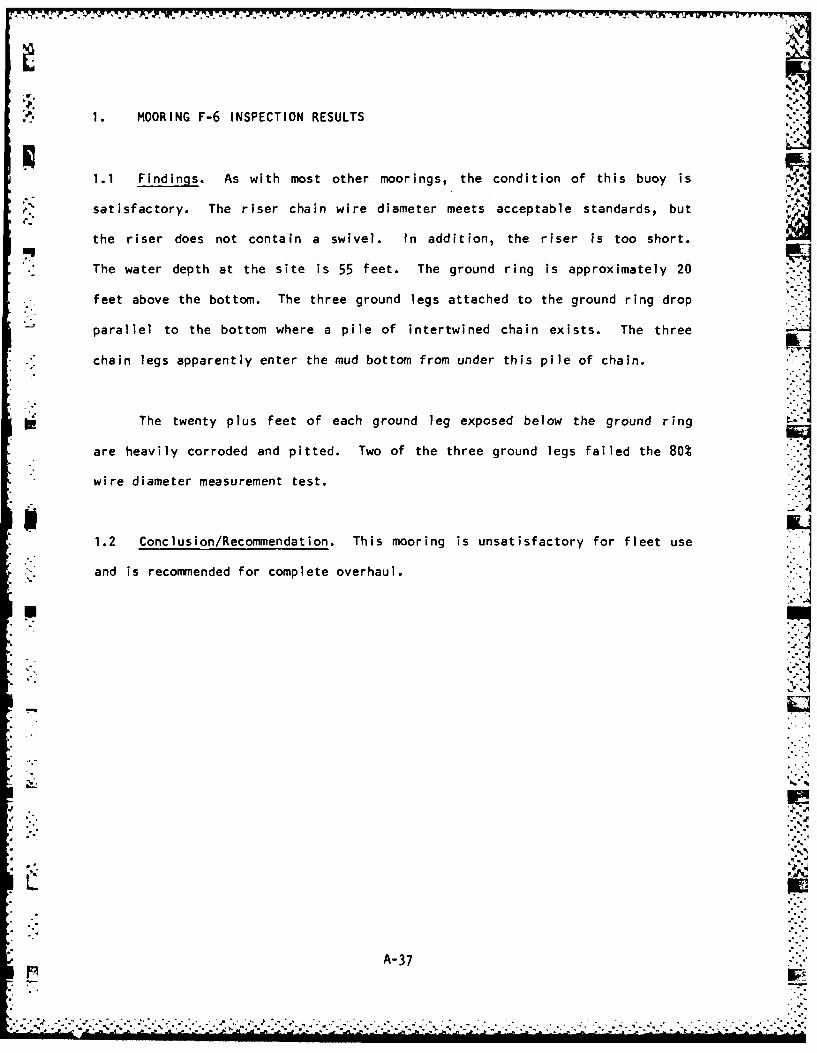
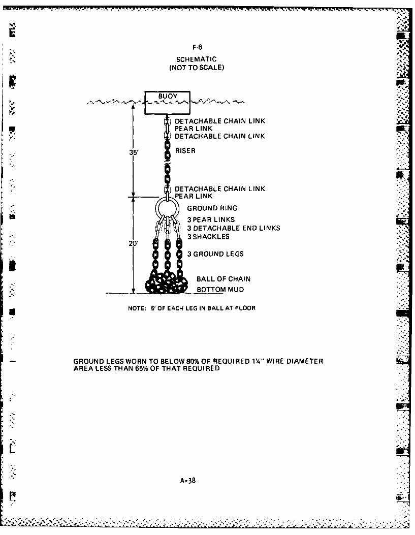
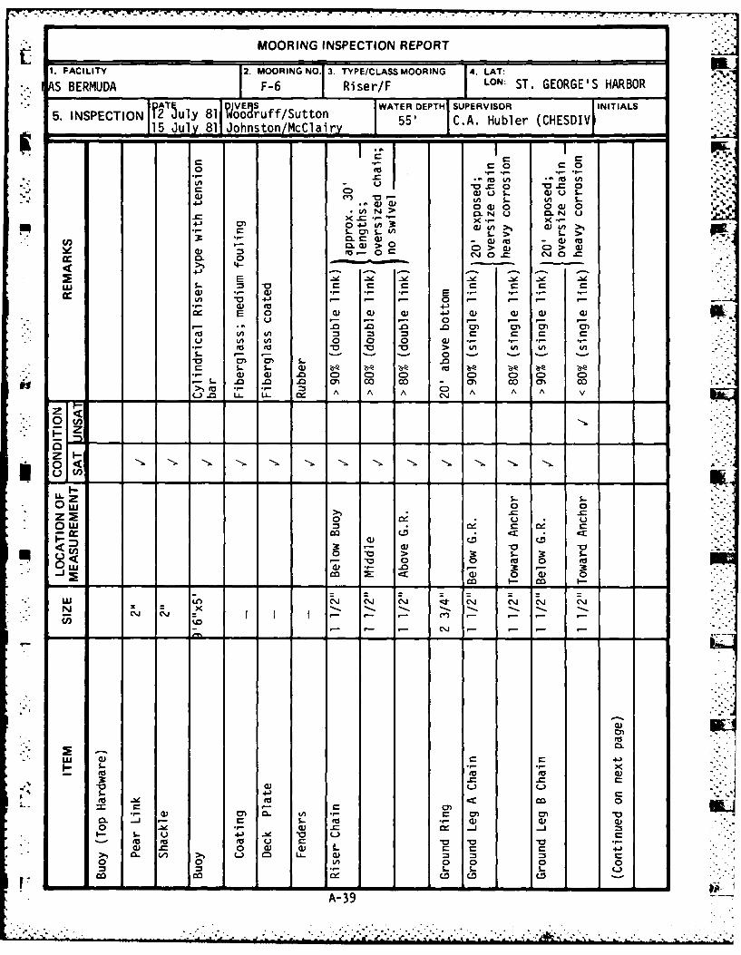
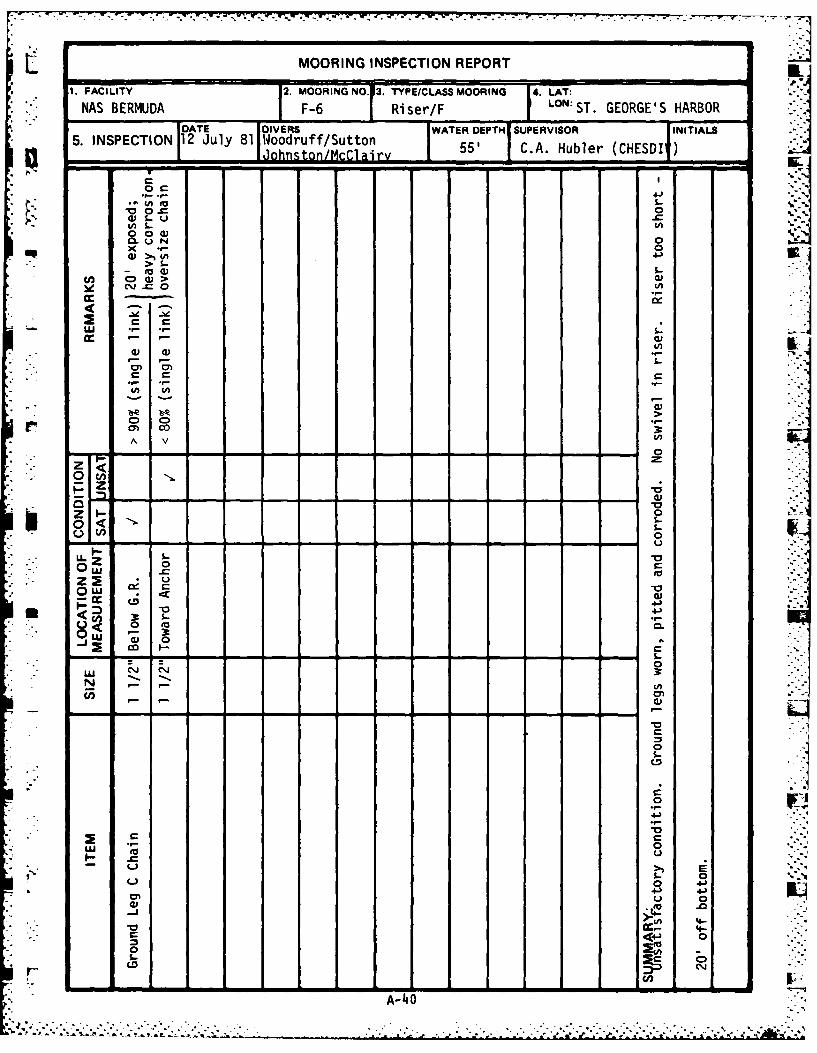
1. MOORING F-6 INSPECTION RESULTS
1.1 Findings. As with most other moorings, the condition of this buoy is
satisfactory. The riser chain wire diameter meets acceptable standards, but
the riser does not contain a swivel. In addition, the riser is too short.
The water depth at the site is 55 feet. The ground ring is approximately 20
. feet above the bottom. The three ground legs attached to the ground ring drop
. parallel to the bottom where a pile of intertwined chain exists. The three OI.J
.* chain legs apparently enter the mud bottom from under this pile of chain.
The twenty plus feet of each ground leg exposed below the ground ring
are heavily corroded and pitted. Two of the three ground legs failed the 80%
wire diameter measurement test.
1.2 Conclusion/Recommendation. This mooring is unsatisfactory for fleet use
"-. and is recommended for complete overhaul.
A-37..
F-.6
SCHEMATIC(NOT TO SCALE)
BUOY
DETACHABLE CHAIN LINKPEAR LINKDETACHABLE CHAIN LINK
35' RISER -
DETACHABLE CHAIN LINKPEAR LINK
GROUND RING
3 PEAR LINKS3 DETACHABLE END LINKS3 SHACKLES
20'3 GROUND LEGS
BALL OF CHAIN.'- BOTTOM MUD"'
NOTE: 5 OF EACH LEG IN BALL AT FLOOR
GROUND LEGS WORN TO BELOW 80% OF REQUIRED 1/4" WIRE DIAMETERAREA LESS THAN 65% OF THAT REQUIRED
A- 38
q. . . . . .. . . . *-*.*
MOORING INSPECTION REPORT
FACILITY 2. MOORING NO 3. TYPE/CLASS MOORING 4. LAT:
S BERMUDA F-6 I Riser/F LON ST. GEORGE'S HARBOR
f2T5 WIVES WATER DEPTH1 SUPERVISOR INITIALS5. INSPECTION Tly 81 ooruff/Sutton 551 C. SRbler(CHESDIV
15 July 81 dohnston/McClair, C .ub r
I n, o - - - -I = -
a. 0 IL. J
0 (1) 0 0ai 0) 3c CA ow o
InN'- 0 "O"J..U O 0..) s- s-
,-- . . . 3 ,- t 0 , 0)n0
( 3 ; r-" 00 - 0) =)
CL 0L )> 00) >
> >4-
" E> , .,- .,- -o o~ o~ o,, o -
0L *- 0s.
a. 0.., .2 0 01) 0) 0) 4-) 4) 0) 0) 0)NO
In0 0 0 0) *
to 0o V 0 V > In In In Ins-- 0
s- s- S. 1) zbe Z; 0A Zo) 4) .0 C0 C) 0) 0D 0 0 0-0 m" 0- 0" 0 m
to- - m A A A 0" A A A v
.. I -- .0 LL. .. -I=
-z
I-I-U4 nO ( e '-
LL , s=- -,.0w 0 0
0) CD tD3* - -) - , V - -
Un 0 "o > 3: &-. 3 S-.- . " , '- .. 0 - ,- 3
co Q . ,n " ) 0 . 0
-U -r -~ C.'J -l - l -
LU a) C 4-)- -0 0
a)) ( L)
1 .- 4-) Ad
cl0 a L) a)0 0 In0 000
cc D CD (D
A-39 -
7. 7.L MOORING INSPECTION REPORTJ
1. F ACILITY j2. MOORING NO. 3. TYPEiCLASS MOORING 4'. LAT:
*NAS BERMUDA jF-6 j Riser/F LNST. GEORGE'S HARBOR
DATE WAESf/utnTER DEPTHI SUPERVISOR JINITIALS
JontnM~ar 55 * C.A. Hubler (HESDI
cv 0
cn 00A v (A
0 C-
-0
0 CL
N L
0
*0
0
o:t 4-
0~
0-4
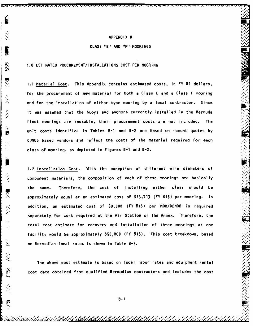
APPENDIX B
CLASS "E" AND "F" MOORINGS
1.0 ESTIMATED PROCUREMENT/INSTALLATIONS COST PER MOORING
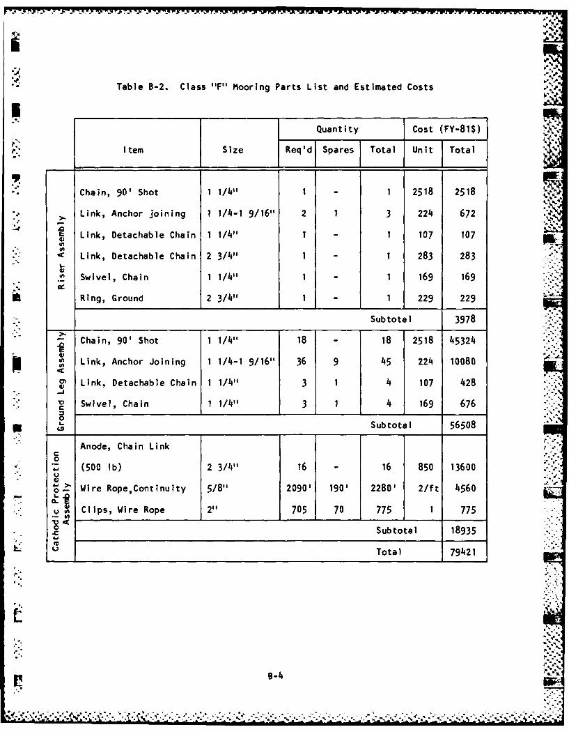
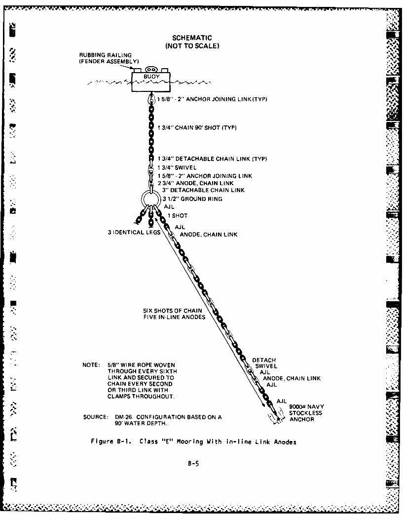
1.1 Material Cost. This Appendix contains estimated costs, in FY 81 dollars,
for the procurement of new material for both a Class E and a Class F mooring
and for the installation of either type mooring by a local contractor. Since
it was assumed that the buoys and anchors currently installed in the Bermuda
fleet moorings are reusable, their procurement costs are not included. The
unit costs identified in Tables B-1 and B-2 are based on recent quotes by
CONUS based vendors and reflect the costs of the material required for each
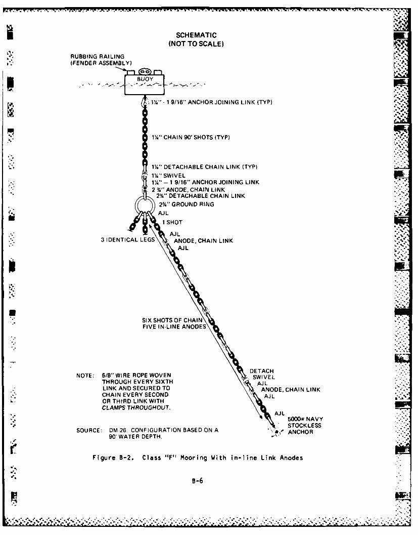
class of mooring, as depicted in Figures B-1 and B-2.
! IL1.2 Installation Cost. With the exception of different wire diameters of
- component materials, the composition of each of these moorings are basically
the same. Therefore, the cost of installing either class should be
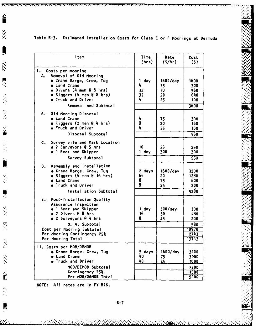
- . approximately equal at an estimated cost of $13,713 (FY 81$) per mooring. In
addition, an estimated cost of $9,000 (FY 81$) per MOB/DEMOB is required
separately for work required at the Air Station or the Annex. Therefore, the
total cost estimate for recovery and installation of three moorings at one
facility would be approximately $50,000 (FY 81$). This cost breakdown, based
on Bermudian local rates is shown in Table B-3.
The above cost estimate is based on local labor rates and equipment rental
cost data obtained from qualified Bermudian contractors and includes the cost
""B-•
- j- - l-, . ' w , ' . .. . . -.. w . . / | .- W.r r r ,- - r'y "UW-.(r.(r W - C- W- r - r Wh .. r -,
of an installation platform and crew, required cranes, riggers, divers,
surveyors, and other required support personnel and equipment. This estimate
also includes 25% contingency funds to cover additional installation costs
that could accrue in the event of inclement weather, equipment malfunctions,
or other unexpected occurences.
B-2o
... : :..:.
' 5
5-2"
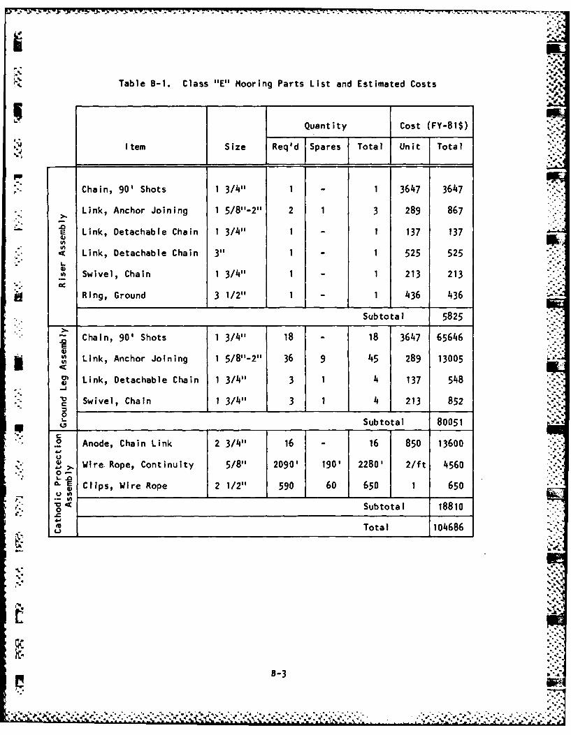
Table B-1. Class "E" Mooring Parts List and Estimated Costs
Quantity Cost (FY-815)
Item Size Req'd Spares Total Unit Total
Chain, 90' Shots 1 3/4" 1 1 3647 3647
Link, Anchor Joining 1 5/8"-2" 2 1 3 289 867
E Link, Detachable Chain 1 3/411 1 1 137 1374)
Link, Detachable Chain 3" 1 1 525 525
i Swivel, Chain 1 3/4" 1 1 213 213
Ring, Ground 3 1/2" 1 1 436 436
Subtotal 5825
" Chain, 90' Shots 1 3/4" 18 18 3647 65646
4."
SLink, Anchor Joining 1 5/811-211 36 9 45 289 13005
IV Link, Detachable Chain 1 3/4" 3 1 4 137 548
Swivel, Chain 1 3/4" 3 1 4 213 852
0____Subtotal 80051
.0 Anode, Chain Link 2 3/411 16 - 16 850 13600
>. Wire Rope, Continuity 5/8" 2090' 190' 2280' 2/ft 45600.
E Clips, Wire Rope 2 1/2" 590 60 650 1 650.2
V Subtotal 18810
M Total 104686
,t-,
* ...-.... -.** *.V
* % . * V''".t V(,-,. V V 1
aI-)
Table B-2. Class "F" Mooring Parts List and Estimated Costs
-",Z
Quantity Cost (FY-81$)
Item Size Req'd Spares Total Unit Total
Chain, 90' Shot 1 1/4" 1 - 1 2518 2518
Link, Anchor joining 1 1/4-1 9/16" 2 1 3 224 672
Link, Detachable Chain 1 1/4" 1 - 1 107 107
" Link, Detachable Chain 2 3/4" 1 - 1 283 283
Swivel, Chain 1 1/4" 1 - 1 169 169
Ring, Ground 2 3/4" 1 - 1 229 229
Subtotal 3978
Chain, 90' Shot 1 1/4"1 18 - 18 2518 45324EE*Link, Anchor Joining 1 1/4-1 9/16"1 36 9 45 224 10080
Link, Detachable Chain 1 1/41" 3 1 4 107 428
. Swivel, Chain 1 1/4" 3 1 4 169 676
I Subtotal 56508
Anode, Chain Link
0" (500 Ib) 2 3/4" 16 - 16 850 13600U
0 Z' Wire Rope,Continuity 5/8" 2090' 190' 2280' 2/ft 4560- E"
• . . Clips, Wire Rope 2" 705 70 775 1 775
0 Subtotal 18935
L Total 79421
S'-4 ...-..
.. :,',,'.'..'', ,'' . '.. .'.'¢ .- .. , , ... ',.-.* : .. '-'.....-.. .. ...... .- - ., -,, ,.*....-... . , ..., .. ,. - .. , -... % '.,,.-.,. --- ,..- .,
SCHEMATIC l,(NOT TO SCALE) 0 4.
RUBBING RAILING ((FENDER ASSEMBLY)
BUOY
1 5/8" -2" ANCHOR JOINING LINK(TYP)
1 3/4" CHAIN 90' SHOT (TYP)
1 3/4" DETACHABLE CHAIN LINK (TYP)
13/4" SWIVEL
1 5/8" - 2" ANCHOR JOINING LINK2 3/4" ANODE, CHAIN LINK
3" DETACHABLE CHAIN LINK3 1/2" GROUND RINGAJ L
1 SHOT
AJ L3 IDENTICAL LEGS ANODE, CHAIN LINK
SIX SHOTS OF CHAINFIVE IN-LINE ANODES
DETACHNOTE: 5/8" WIRE ROPE WOVEN SWIVEL
THROUGH EVERY SIXTH AJLLINK AND SECURED TO ANODE, CHAIN LINKCHAIN EVERY SECOND AJL
- OR THIRD LINK WITHCLAMPS THROUGHOUT.
AJLS9000t N AV Y ~,- STOCKLESS
SOURCE: DM-26. CONFIGURATION BASED ON A \, ATCKLESS90' WATER DEPTH. ANCHOR
Figure B-1. Class "E" Mooring With in-line Link Anodes
B-5
r~ r. ~ ~. ~ fl~ .. Yi r NT~ ..'' '.T"Trw1* -Fv puTv- - *- S
SCHEMATIC(NOT TO SCALE)
RUBBING RAILING(FENDER ASSEMBLY)
BUOY
Ij1%"' - 1 9/16" ANCHOR JOINING LINK(TP
2 %" CAN90,SHOTS (TYPK
2%' DETACHABLE CHAIN LINK(TP
2%" GROUND RINGAJ L
b~ iSHOT
AJ L3 IDENTICAL LEGS ANODE, CHAIN LINK
AJ L
SIX SHOTS OF CHAINFIVE IN-LINE ANODES
DTACHNOTE: 5/8" WIRE ROPE WOVEN SWIVEL
THROUGH EVERY SIXTH AJLLINK AND SECURED TO ANODE, CHAIN LINKCHAIN EVERY SECOND AJLOR THIRD LINK WITHCLAMPS THROUGHOUT.
AJ L5000& NAVYSTOCKLESS
SOURCE: DM 26. CONFIGURATION BASED ON A 'ACO90 WATER DEPTH.
rFigure B-2. Class "F" Mooring With in-line Link Anodes
B-6
W.~~~~~~" IT- W-W. 7 °F. 7- _
Table B-3. Estimated Installation Costs for Class E or F Moorings at Bermuda
Item Time Rate Cost(hrs) ($/hr) ($)
I. Costs per mooringA. Removal of Old Mooring
* Crane Barge, Crew, Tug 1 day 1600/day 1600 -
* Land Crane 4 75 300* Divers (4 men @ 8 hrs) 32 30 960* Riggers (4 men @ 8 hrs) 32 20 640* Truck and Driver 4 25 100
Removal and Subtotal 3600
B. Old Mooring Disposal* Land Crane 4 75 300* Riggers (2 men @ 4 hrs) 8 20 160* Truck and Driver 4 25 100
Disposal Subtotal 560
C. Survey Site and Mark Locationa 2 Surveyors @ 5 hrs 10 25 250* 1 Boat and Skipper 1 day 300 300
Survey Subtotal 550
D. Assembly and installation* Crane Barge, Crew, Tug 2 days 1600/day 3200 -"* Riggers (4 men @ 16 hrs) 64 20 1280* Land Crane 8 75 600* Truck and Driver 8 25 200
Installation Subtotal 5280
E. Post-Installation QualityAssurance Inspection "* 1 Boat and Skipper 1 day 300/day 300o 2 Divers @ 8 hrs 16 30 480o 2 Surveyors @ 4 hrs 8 25 200
Q. A. Subtotal 980Cost per Mooring Subtotal 10970Per Mooring Contingency 25% 2743Per Mooring Total 13715-
II. Costs per MOB/DEMOBo Crane Barge, Crew, Tug 5 days 1600/day 32009 Land Crane 40 75 3000 ::
* Truck and Driver 40 25 1000.'..,MOB/DEMOB Subtotal 7200Contingency 25% 1. 0 ..... ".... 1Per MOB/DEMOB Total 9000
NOTE: All rates are in FY 81$.
B-7
APPENDIX C
PHOTOGRAPHS
This Appendix contains photographs taken above and below the surface of
the water, which depict the condition of some of the Bermuda fleet mooring
components.
1
C-
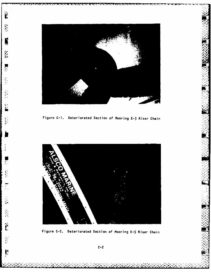
Figure C-1. Deteriorated Section of Mooring E3RseCai
4-4,
Figure C-2. Deteriorated Section of Mooring E-5 Riser Chain
C- 2
- - - -- -- - -..... .
C-3'
UUUJUl UUUJLUUILIUUUUUUUUUUUUUUUUl. UUU .N C L A S 1F IED U
~T INE __
R 30110OZ JUN 81
FM UCT ONE
TO CHESNAVFACENGC'4 ,ASHINGTON DC 4w
UNCLAS /1 SuRJ: BE~eUDjA 4'DDRING INSP
1. REQUEST ENGINEE:RIN1G SUPPORT FOR SU6J PROJECT 6-19 JUL 81.
2. FUNDS IN THiE AMOUNIT (6K) TO bE F6D ON DD FORM 1149 UINDERACCT (jATA; 171 1804.6O2A/000/57O34/0/0b25e3/2D/3O1i!1/0O1182B701NA,
OLVR:CHESNAVFACENGtOm 4 ASHINGTDN OC(83...-ACT
RTD:O0-000/COPIE3 0008
568734/181 1 OF I MI 0276 181/18:58Z 301100Z JUN 81I ;RXOy002.5 UCT ONE
UUUJIUUUUUUUUUULJUUUUUUUUUUUUUUUUUUUU U N CLA SS IF I ED -U
uuuiuuuuuuuuuuuvuUUUUUUUUUU.U
UUU JUUJUU'JUUU U'uj UUUUUUUUUUuIJUUUUUUU J!U U N C L A 3 S I F I E O UUUUUUUUUULUUUUUUUUuUUULUUUUUUUUU". ,
::'.;.,.'-
ROUTINE
R 04122O8Z AJG 81.
FM CHESNAVFACENGCOM NASHINGTON DC
TO NAS SER4UDA
INFO CONAVFACE4GCO i ALEXANDRIA VA LANTNAVFACENGCUM NORFOLK VAUCT ONE
UNCLAS //N11153//
SUBJ: iERMUDA FLEET MOORING INSPECTION
1, DURIN T4E PERIOD 8-15 JULY Alt UCT-ONE DIVERS CONDUCTED UNDER-WATER INSPECTIONS OF TEN (10) FLEET MUOkINGS IN 4ERMUDA. T4IS IS APRELI.AINARY REPORT OF THE FINDINGS OF THIS INSPECTIUN.
2. GENERAL CONDIIIO' EACH ,0O6RING FOLLO45:MOORING FINDINGS CONDITI3N
E-1 CHAI LEGS INTERTAINDED FIRST 60 UNSAFE FORFEET 8ELOo GRUUND RING. ONE RATED L3ADANCHOR dACKhARDS (FLUKE POINTINGAWAY FROM1 iUDY), MUOHING HASMOVED AND COULD FAIL UNDEH LOAD,
MOORING FINDINGS CONDITIO-.E-2 WIRE DIAMETER OF RISER CHAIN UNSAFE FOR
WORN OD.4 TJ 7/8 IN THICKNEbS, RATED L3AD --E-3 WIRE DIAMETER OF RISER CHAIN UNSAFE FOR
WORN D044 TO 3/4 IN THICHNESS, RATEO L3AOE-I RISER CHAIk'/JEf.ELRY SATISFACTORY QUESTIOnAdLE
GROUND RIN;/LEGS 6URIED IN MUDAND COULD MOT BE RAISED WITH-TrO-TON LIFT UAG, CO4DITION/ORIENTATIOI LEGS UNKNOUKN.,
E-S WIRE DIAMETER OF RISER CHAIN UNSAFE FflRWORN DO0N TO 7/5 IN THICKNESS, RATED LOADLEG CHAIN PASSES THROUGH GROUND .- -
RING. -:.F-I RISER, GROUND RING, LEG CONDITION SATISFACTORY
AND ORIENTATION SATISFACTORY,F-2 ONE OF THREE CHAIN LEGS MISSING. UNSAFE FOR
DLVR:CHESNAVFACENGCD4 WASHINGTON DCCO)..ORIG . . ,
RTD:O00OO-00/COPIES 0008
766366/216 1 OF 2 Mi 0164 2lb/16:59Z 0Li122Z AUG 81CSN:RxOYO11 CSESNAVFACENGC4 WASIINGTON DC
UUUUU U UUU UU U UU UU U UUUUUUUUU UUU UUUUU U..-."-:'
U U N C L A S SI F I E D UUUUUUUUUULJUUUUuUUUUUUUUUUUUUUUUUUUUU"
D-2.................................................
._,d. .d.
UUuUUuuUUUJ]UUUUUUUUUUUUUUUUUUUUUUUU U N C L A S I F I E U UUUUUUUUUUUUUUUUUUUUUUUUUUUUUUUUUUUU
,'"
)'..
I .-RATED L3AD
F-3 BUOY hAS 8-10 DEGREE TRIM ANGLE, QUESTIOJAdLEMOORING FINDING CO4DITION
LEG CHAIN PILED N dOTTOM. LEG ..-
ORIEJTATItP UNKNOWN,PARALLEL ETRv OF LEGS INTO BOTTOm4,LEG RIE[AT ION IJNKON,
F-6 WIRE DIAMETER ALL CrIAIN LEGS 8ELOa UNWSAFE FOR80 PERCENT 3F INITIAL SIZE, MOUND RATED L3ADOF CHAIN ON 8OTT ,,-
3. ONLY OSJE .0OURING (F-I) FULLY SATISFACTORY FOR FLEET !SE.CONDITION OF MIORIt1GS E-4, F-3 AND F-4 UNCEkTAIN. CAUT13N SHOULDBE USED IN USING THESE &UDYS LSPECIALLY AS STOR MOORINGS. REMAIlId GBUOYS DU NOT MEET SPECIFICATION REQuIREMENTS AND SHUULD MD)T BE USED.
4. A DETAILED INSPECTION qEPOR IS I4 PREPARATION ANU, UPO4 CD"4PLETIONP AILL BE FORNARDED TO INTERESTED COMMANDS,ST
"'."
'.".' -
768366/216 2 OF 2 M 0164 216/16:59Z Ol4122qZ AUG 81CSN:RXOYO0161 CMESNAVFACENGCOA bASIINGTON icC
, ..
,... ..."
uUUUUUU' "juUuUUUUUUUUUUUUUUUUUU 'UUUU J__'U L a, , C L A 3 3 1 F I E D ,u~~~UUUUUUUUUUUUUUUUUUUlIUUUUUUUUUUUIJUUUU
-..D-3".
"
- .. '
j ______________ .4
-.4
-p.
,~1~
.4.
**5
-.4 -%-.
-.44
.1*
6-86C,
.4.
4%
C, j
I,
S.-C-, /1C-S.
C.
C.
p
'C
S..
.4
* .4'