Embed Size (px)
Citation preview

Class LixXll
Book. Xi^ .
CopyrightM.
COPYRIGHT DEPOSIT.

Digitized by the Internet Archive
in 2011 with funding from
The Library of Congress
http://www.archive.org/details/patternmakingkinOOcolv


THE HILL KINK BOOKS
PATTERNMAKING KINKS
THE HILL KINK BOOKS
Compiled by F. H. Colvin and F. A. StanleyAssociate Editors of the American Machinist
Each cloth, 4x6, illustrated, 50 cents postpaid
ORDER NOWPRESS TOOL KINKS
SCREW THREAD KINKSPATTERNMAKING KINKSMILLING MACHINE KINKS
REPAIR KINKSTOOLMAKERS' KINKS
JIG AND FIXTURE KINKSDRILL PRESS KINKS
DRAWING ROOM KINKSSCREW MACHINE KINKS
HILL PUBLISHING COMPANY505 PEARL ST., NEW YORK CITY
6 BOUVERIE STREET, LONDON, E.C., ENG.
American Machinist— Power— The Engineering and Mining Journal
THE HILL KINK BOOKS
Patternmaking Kinks
COMPILED BY
F. H. COLVIN and F. A. STANLEY'i . .
'. .
Associate Editors of American Machinist
1908
HILL PUBLISHING COMPANY505 PEARL STREET, NEW YORK6 BOUVERIE STREET, LONDON, E.C.
American Machinist — Power— The Engineering and Mining Journal
Copyright, 1908, by the Hill Publishing Company
UBKARY of CONGRESS.
TwoOoplei Receive
J
MAR U 1908
|aU8» A *Xfc Nu.
Z '
COPY 3.
HVtf Publishing Company, New York, U.S.A.
INTRODUCTORY WORD
The kinks and other information given in
this book have been selected from the experi-
ence of thoroughly practical men, as originally
published in the American Machinist. This vol-
ume forms one of a series of this nature, aiming
always to make available out-of-the-way infor-
mation when most wanted. In this form the
Kink Books, which can be kept in the tool-chest
or the pocket, and always referred to, will, we
feel, meet a demand and serve a good purpose.
F. H. Colvin.
F. A. Stanley.
New York, November, 1907.
fiff

PATTERNMAKING KINKS
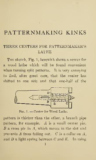
THREE CENTERS FOR PATTERNMAKER'SLATHE
The sketch, Fig. 1, herewith shows a center for
a wood lathe which will be found convenient
when turning split patterns. It is very annoying
to find, after great care, that the center has
shifted to one side and that one-half of the
E £
MFig. 1. — Center for Wood Lathe.
pattern is thicker than the other, a branch pipe
pattern, for example. A is a small center pin,
B a cross pin in A, which moves in the slot and
prevents A from falling out. C is a collar on A,
and D a light spring between C and E. In using
1
2 PATTERNMAKING KINKS
this center it is not necessary to make a center
hole in the wood — simply locate the center with
a pencil and drop the center point A on it. A is
not forced into the wood, but backs into the
driver until the jaws engage in the wood. Both
head and tail centers are made with spring points.
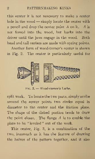
Another form of wood-turner's center is shown
in Fig. 2. The center is particularly useful for
vFig. 2. — Wood-turner's Lathe.
split work. To locate the two parts, simply scribe
around the center points two circles equal in
diameter to the center and the friction plate.
The shape of the dished portion tends to draw
the point closer. The flange A is to enable the
plate to be " leveled " out of the work.
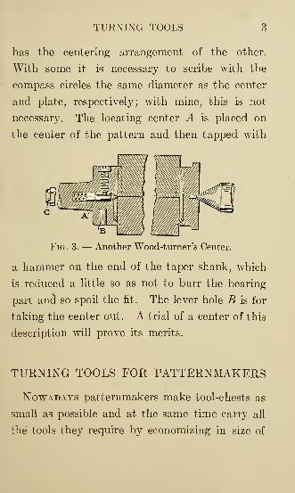
This center, Fig. 3, is a combination of the
two, inasmuch as it has the feature of drawing
the halves of the pattern together, and it also
TURNING TOOLS 3
has the centering arrangement of the other.
With some it is necessary to scribe with the
compass circles the same diameter as the center
and plate, respectively; with mine, this is not
necessary. The locating center A is placed on
the center of the pattern and then tapped with
Fig. 3. — Another Wood-turner's Center.
a hammer on the end of the taper shank, which
is reduced a little so as not to burr the bearing
part and so spoil the fit. The lever hole B is for
taking the center out. A trial of a center of this
description will prove its merits.
TURNING TOOLS FOR PATTERNMAKERS
Nowadays patternmakers make tool-chests as
small as possible and at the same time carry all
the tools they require by economizing in size of
4 PATTERNMAKING KINKS
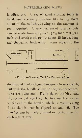
handles, etc. A set of good turning tools is
handy and necessary, but few like to lug them
about in the tool-chest owing to the amount of
room required. A very neat set of turning tools
can be made from JxJ inch, JxJ inch and |xl
inch tool steel; each tool is about 15 inches long
and shaped on both ends. Some object to the
^v
f
/J
^ Diamond Point j
\ ( 1
JRound Nose >
)
1
1
VFig. 4. — Turning Tool for Patternmakers.
double-end tool as being dangerous to work with,
but with the handle shown the objectionable fea-
tures are overcome. Fig. 4 shows the idea, and
the reader will see that the tool reaches almost
to the end of the handle, which is made a snug
fit so that it may be slipped on and off. The
handles can be made of wood or leather, one for
each size of steel.
THE PATTERNMAKER'S LATHE 5
THE PATTERNMAKER'S LATHE
Not every shop possessing a patternmaker's
lathe is deriving the good from it which might
be obtained, simply through the lack of proper
tools and accessories.
By a patternmaker's lathe, in distinction from
an ordinary hand or speed lathe, we mean one
with a movable carriage, having a slide or com-
pound rest attached, holding a tool-post. An
ordinary rest-holder and set of rests usually go
with one of these lathes in addition, but many
believe in discarding this feature entirely, and,
when using ordinary hand tools, just place a
plain bar in the tool-post and use this for a rest
instead; for it does not pay to be continually
changing the rest-holder. Even this will not in
all cases be necessary, for it often happens that
when some corner is to be rounded or fillet made,
which cannot be conveniently done with the tool
in the tool-post, a hand tool can be • used to
finish the place by holding it right on this fixed
tool in lieu of a rest.
It is not every job by any means that can be
6 PATTERNMAKING KINKS
most economically done with fixed tools, and here
is where good judgment and common sense must
take their turn, using the carriage and slide-rest
where time can be saved, and the hand tools
when their use will be the most expeditious.
Often a combination of both ways on the same
piece of work is best. For very small turning, a
regular speed lathe is of course the handiest.
But, to return to the subject, let us examine the
patternmaker's lathe somewhat closely, and try
to note a few features that will help to do accurate
work quickly and easily.
One with a swiveling headstock is far ahead of
those of the fixed type, and it should move
through an arc of at least 3 degrees each side of
the mark, and when at this mark it is a most
excellent plan to have it located by a taper pin
set just back of the index mark on the movable
portion of the headstock. This makes the setting
sure before the screws are tightened, without
relying on graduations which a careless workman
will occasionally fail to match properly, and then
the work done by the carriage is sure to be
tapering. We know of two shops, each having
THE PATTERMAKER'S LATHE 7
one of the most widely known makes of pattern-
maker's lathe, that have had the taper plug fitted
themselves, because the makers did not.
It has been our experience that, on general
pattern work, the tailstock will not be set out of
line once in fifty times compared with the head-
stock, for the latter is constantly being shifted
to get the necessary draft on all face-plate work
of any depth. The compound rest on the car-
riage should swivel, and be provided with grad-
uations from to 90 degrees in each direction, to
facilitate such turning as gear blanks, etc.
About the most important feature, outside of
the bare lathe itself, is the question of tools for
the tool-holder. We have had a chance to see
and study the effect of quite a number of shapes,
in the different shops, but have not seen a style
that will cut smoother and faster than these.
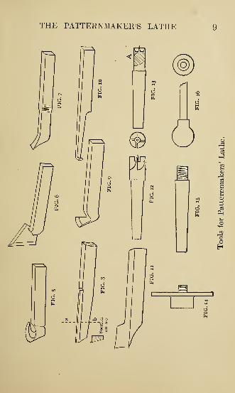
Fig. 5 is a roughing-out tool. The cutting
edge should slant downward somewhat as it ap-
proaches the end or tail, to give a drawing cut,
and the outside face ought to overhang at least
10 degrees from a perpendicular all the way
around, so as to take hold nicely at the very
8 PATTERNMAKING KINKS
edge, and not have any point of contact below
where it is doing work, to retard its action. An
emery wheel about 8 inches in diameter gives a
good concave to the outer face, and when this
tool has a few finishing touches with an oil stone,
it is surprising to see the heavy chips it will take
from a rough piece, without even previously
removing the corners.
Fig. 6 shows the "arrow point" tool for
finishing, and it should be set slightly angling to
the work. When properly sharpened it will cut
almost as smooth as glass, and on straight work,
like rolls, etc., it works as nearly perfect as one
could wish. The action, it will be noticed, is
similar to a wood-turner's skew chisel.
Fig. 7 is a cutting-off tool, which does not tear
and scrape like the ones generally used, that are
flat on top. It is intended to be sharpened on
an emery wheel, about 6 or 8 inches in diameter,
and then be touched up on an oil stone, as in
fact are all of them. The curvature on the upper
side of this tool allows it to enter the work easily
and take a fast cut, while the curve below re-
moves the stubbed end frequently seen on tools
THE PATTERNMAKER'S LATHE
10 PATTERNMAKING KINKS
of this class. One of these tools, made in every
respect like Fig. 7, except with a wider cutting
face, is excellent for shouldering down on work.
With it a number of cuts can be made down to
almost the diameter required, then get the exact
diameter, and finish by moving the carriage
along. The tool cuts quite smoothly moved
along in this manner, but not quite as well as
the "arrow point."
Fig. 8 is a boring tool, and there should be
one right and one left. We have used tools of
this shape a great deal, and for deep boring
know of nothing better. They also work equally
well on outside work and are especially useful
when the piece being turned is too large in diam-
eter to slide the carriage along under it, for it
can be placed in the tool-post in such a manner
as to overhang a long distance, and work clear to
its limit.
Fig. 9 is a nice tool for facing off segments and
the surface of any disk which may be on the
face-plate. It works quite well also when turning
on the outside diameter, but is especially for
facing.
THE PATTERNMAKER'S LATHE 11
Fig. 10 is a boring tool which is useful in holes
of small diameter where the one shown in Fig. 8
cannot be conveniently operated. Fig. 11 shows
a tool for general work, which is good for smooth-
ing and shouldering down. It will be noticed
that it has two cutting edges which can be used,
and the top is shaped by the curve of the emery
wheel something as in Fig. 7. The angle of the
point should be less than a right angle, as, if so
made, the tool can be set so as to be started in
with the slide-rest, and then be stopped and
moved along by the carriage. A much deeper
chip can be taken with this tool when the car-
riage is moved than with the one shown in Fig. 7,
as its action is more of a drawing cut.
We want to find a little fault with the spur
and cup centers, as sometimes sent out by the
makers with a new lathe, and will give our
reason for it: The spur or point in each of these
is apt to be too large. A very large percentage
of work performed on a pattern-making lathe
between centers is done in halves, and it is very
important indeed that the lathe center comes
exactly in the joint between the halves men-
12 PATTERNMAKING KINKS
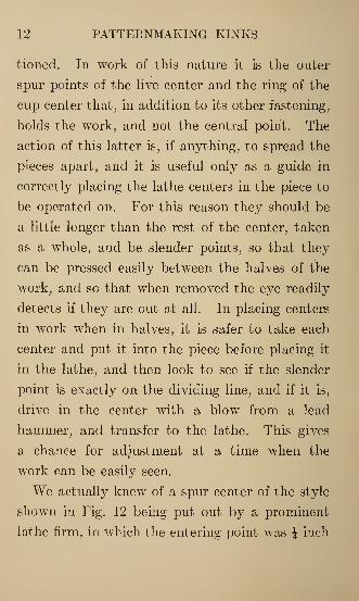
tioned. In work of this nature it is the outer
spur points of the live center and the ring of the
cup center that, in addition to its other fastening,
holds the work, and not the central point. The
action of this latter is, if anything, to spread the
pieces apart, and it is useful only as a guide in
correctly placing the lathe centers in the piece to
be operated on. For this reason they should be
a little longer than the rest of the center, taken
as a whole, and be slender points, so that they
can be pressed easily between the halves of the
work, and so that when removed the eye readily
detects if they are out at all. In placing centers
in work when in halves, it is safer to take each
center and put it into the piece before placing it
in the lathe, and then look to see if the slender
point is exactly on the dividing line, and if it is,
drive in the center with a blow from a lead
hammer, and transfer to the lathe. This gives
a chance for adjustment at a time when the
work can be easily seen.
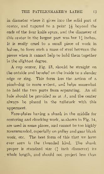
We actually knew of a spur center of the style
shown in Fig. 12 being put out by a prominent
lathe firm, in which the entering point was J inch
THE PATTERNMAKER'S LATHE 13
in diameter where it gives into the solid part of
center, and tapered to a point ^f beyond the
ends of the four knife spurs, and the diameter of
this center in the largest part was but 1J inches.
It is really cruel to a small piece of work in
halves, to force such a mass of steel between the
pieces when it cannot help to hold them together
in the slightest degree.
A cup center, Fig. 13, should be straight on
the outside and beveled on the inside to a slender
edge or ring. This form has the action of a
pinch-dog to some extent, and helps somewhat
to hold the two parts from separating. An oil
hole should be provided as at A, and the center
always be placed in the tailstock with this
uppermost
.
Face-plates having a shank in the middle for
centering and chucking work, as shown in Fig. 14,
are used in some places, and cannot be too highly
recommended, especially on pulley and gear blank
work, etc. The best form of this that we have
ever seen is the threaded kind. The shank
proper is standard size (f inch diameter) its
whole length, and should not project less than

14 PATTERNMAKING KINKS
J inch nor more than f inch, and around this
shank or spindle is a very thin thread like a
knife edge, at the rate of 8 to the inch, and
the more like a knife edge this thread can be the
better, for then it will not injure the hole in the
work in the least, by throwing it out of center,
or hurt it for receiving core print shanks or
plugs of any kind. It is better to have this
thread start at least Txg- inch back from the end,
so that the hole in the work can be squarely
placed before commencing to screw it back against
the face-plate.
It will be found that a vast deal of work can
be done without using any wood screws through
the face-plate to help hold, relying only on the
threaded shank.
Sometimes this centering principle is needed to
be used in connection with some face-plate not
fitted with this device, in which case have a
lathe center made as in Fig. 15, with the end
fixed exactly like the one in Fig. 14, so that it
can be used equally well with all the face-plates
belonging to the lathe, and projecting beyond
them the same distance. When this latter scheme
TOOL-POST FOR PATTERN SHOP 15
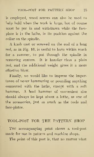
is employed, wood screws can also be used to
help hold when the work is large, but of course
must be put in and withdrawn while the face-
plate is in the lathe, in its position against the
collar on the spindle.
A knob cast or screwed on the end of a long
rod, as in Fig. 16, is useful to have within reach
for a rammer, to put through the spindle in
removing centers. It is handier than a plain
rod, and the additional weight gives it a more
effective blow.
Finally, we would like to impress the impor-
tance of never hammering or pounding anything
connected with the lathe, except with a soft
hammer. A lead hammer of convenient size
should always be kept about a lathe, as one of
the accessories, just as much as the tools and
face-plates.
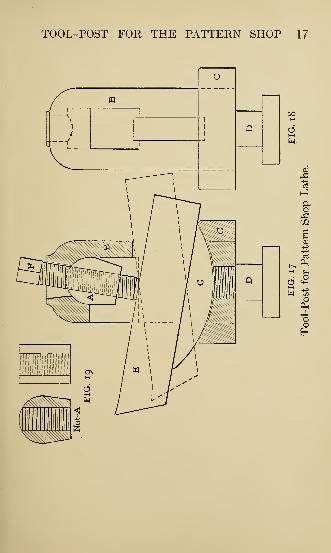
TOOL-POST FOR THE PATTERN SHOP
The accompanying print shows a tool-post
made for use in pattern and machine shops.
The point of this post is, that no matter what
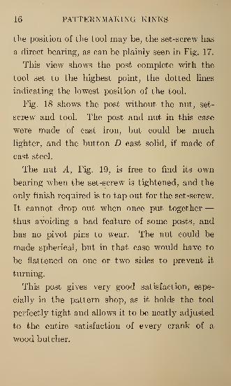
16 PATTERNMAKING KINKS
the position of the tool may be, the set-screw has
a direct bearing, as can be plainly seen in Fig. 17.
This view shows the post complete with the
tool set to the highest point, the dotted lines
indicating the lowest position of the tool.
Fig. 18 shows the post without the nut, set-
screw and tool. The post and nut in this case
were made of cast iron, but could be much
lighter, and the button D cast solid, if made of
cast steel.
The nut A, Fig. 19, is free to find its own
bearing when the set-screw is tightened, and the
only finish required is to tap out for the set-screw.
It cannot drop out when once put together—thus avoiding a bad feature of some posts, and
has no pivot pins to wear. The nut could be
made spherical, but in that case would have to
be flattened on one or two sides to prevent it
turning.
This post gives very good satisfaction, espe-
cially in the pattern shop, as it holds the tool
perfectly tight and allows it to be neatly adjusted
to the entire satisfaction of every crank of a
wood butcher.
TOOL-POST FOR THE PATTERN SHOP 17
u
i
i
i
pq
1
QJ
I
r
fmi IMMl1 /J^\S^>
Q
1 />^\s1 AV\VC\\\X\
\Mw//<
oH
18 PATTERNMAKING KINKS
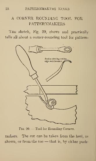
A CORNER ROUNDING TOOL FORPATTERNMAKERS
The sketch, Fig. 20, shows and practically
tells all about a corner-rounding tool for pattern-
Fig. 20. — Tool for Rounding Corners.
makers. The cut can be taken from the heel, as
shown, or from the toe — that is, by either push-
A HANDY TOOL-CHEST 19
ing or pulling — and by tipping up or down the
amount of cut is regulated. It is one of the
most useful tools for a patternmaker's kit.
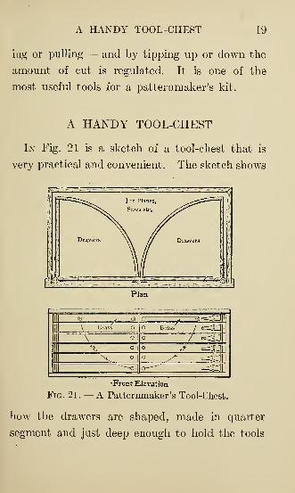
A HANDY TOOL-CHEST
In Fig. 21 is a sketch of a tool-chest that is
very practical and convenient. The sketch shows
Plan
7^<g7^g[
•Front Elevation
Fig. 21. — A Patternmaker's Tool-Chest.
how the drawers are shaped, made in quarter
segment and just deep enough to hold the tools
20 PATTERNMAKING KINKS
without putting one on top of the other. Each
drawer has an ornamental brass hinge which also
serves the purpose of a corner bracket. The
hinges swing on a 4-inch rod, which extends
from top to bottom of box.
The drawer pulls, as shown, serve two purposes:
to open one drawer at a time, or all at once.
This latter is accomplished by a brass plate, as
shown, which has a hole drilled near one end
through which the pull in the upper drawer
passes. The plate is made long enough to ex-
tend down to pull on the lower drawers. When
in a vertical position the plate is under all the
drawer pulls, which thus provides a means of
opening all the drawers at once.
Before building the chest make a sketch of the
drawers full size. This shows how large to make
the chest, which can be put together according
to the ideas of the maker. Opening in the front,
the chest is intended to be placed on or under
the bench as preferred. It should be large enough
to hold all the tools a patternmaker needs, but
no larger than necessary.
As shown in the sketch, all the planes, saws,
A PORTABLE CASE 21
etc., are put in the back of the chest and can be
reached at once.
A PORTABLE CASE FOR PATTERN-MAKERS' TOOLS
Some patternmakers use a trunk as a tool-
chest. This has a nice appearance to one trav-
eling, but when moving around, a fellow does
not always find all the modern conveniences,
and quite often he has to use his tools right from
whatever he brings them in, so he should have
something easy to get at.
Fig. 22 shows a case of drawers which is handy.
At the end of the bench it serves simply as a
case, and if there is not room it will go under
the bench out of the way, still being convenient.
There is not so much trouble making one as in
making a chest, and it does for case and chest
combined. It is surprising how much can be
gotten into a very small space without crowding
at all, if calculated right. The top drawer is just
the depth of the saws, the bottom one deep
enough for a jointer, and all of them long enough
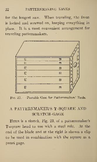
22 PATTERNMAKING KINKS
for the longest saw. When traveling, the front
is locked and screwed on, keeping everything in
place. It is a most convenient arrangement for
traveling patternmakers.
ea ®. B2 ®
£5 is
IS]
E s
® EI
Fig. 22. — Portable Case for Patternmakers' Tools.
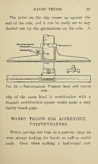
A PATTERNMAKER'S T-SQUARE ANDSCRATCH-GAGE
Here is a sketch, Fig. 23, of a patternmaker's
T-square head to use with a steel rule. At the
end of the blade and at the right is shown a clip
to be used in combination with the square as a
panel gage.
HANDY THINGS 23
The point on the clip comes up against the
end of the rule, and it can be easily set to any
desired size by the graduations on the rule. A
Piece of Saw Steel for
Clamping Gib,
Fig. 23. — Patternmakers' T-square head and scratch
gage.
clip of the same kind in combination with a
Starrett combination square would make a very
handy bench gage.
HANDY THINGS FOR APPRENTICEPATTERNMAKERS
While serving our time in a pattern shop we
were always looking for handy as well as useful
tools. Once when making a half-round core
24 PATTERNMAKING KINKS
box about 2 inches in diameter, when it was
sandpapered it was measured and found that a
little too much had been rubbed on the edges
and consequently it was not a true box and was
out of size. Well, of course, a first-year boy
does not always know just how to remedy a
mistake, except to get out a new piece of stock.
A journeyman working near saw the trouble and
showed what he called a "blind center," and sug-
gested in making one like it to lay out the ends
again and plane the box deeper and dress off the
top to correspond.
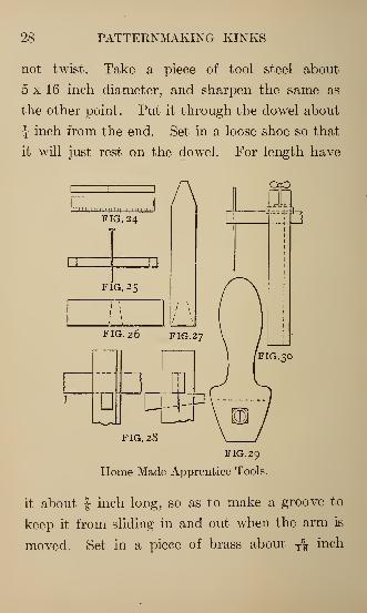
Fig. 24 shows the blind center. Take a piece
of maple or cherry, say about 10 x f by T7g inch
thick, and space it off in sixteenths. Next glue
on a small piece at the middle the same thickness
as the stick; about f diameter is large enough.
Then take a small point and prick a hole in the
joint of the two pieces half-way from each end
cf the long piece. In using this, place the stick
across the top of the box, being sure to get it in
the center, then set your dividers in the center
hole and you can scribe a half-circle on the end
of the box.
HANDY THINGS 25
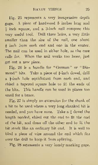
Fig. 25 represents a very inexpensive depth
gage. A piece of hardwood 5 inches long and
J inch square, and a 3-inch nail compose this
very useful tool. Drill three holes, a very little
smaller than the size of the nail, one about
f inch from each end and one in the center.
The nail can be used in either hole, as the case
calls for. When the nail works too loose, just
get out a new piece.
Fig. 26 is a handle for "German" or "Dia-
mond" bits. Take a piece of f-inch dowel, drill
a J-inch hole equidistant from each end, and
chisel a tapered square hole to fit the ends of
the bits. This handle can be used in places too
small for a brace.
Fig. 27 is simply an extension for the shank of
a bit to be used where a very long shanked bit is
needed, and you have none. Take a f dowel the
length needed, chisel out the end to fit the end
of the bit, and dress off the other end to fit the
bit stock like an ordinary bit end. It is well to
bind a piece of wire around the end which fits
over the drill to keep it from splitting.
Fig. 28 represents a very handy marking gage.
26 PATTERNMAKING KINKS
A piece of maple f xlx5 inches makes the
upright , and a piece f x f x 6J inches makes the
arm. Lay out the hole for the arm about f inch
from the end through the widest side and cut
out so that the arm can just slide through freely
and not have a chance to twist. Then lay out
on the narrow side the hole for a wedge of maple
f inch thick, tapering from J to J inch. Have
the top of the hole just cut through the lower
part of the hole for the arm. In making the
wedge have the taper all on one side, leaving the
top side straight. Use a piece of y1^- inch diam-
eter tool steel for the scratcher on the end of
the arm about an inch long. Sharpen this as
you would a pencil, wedge-like, having the flat
part parallel with the front of the upright. You
can sharpen it so that when it is used it will cut
a hair line. That is one of the points which
show neat workmanship. Round the back side of
upright for inside curves.
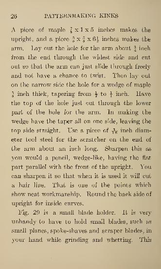
Fig. 29 is a small blade holder. It is very
unhandy to have to hold small blades, such as
small planes, spoke-shaves and scraper blades, in
your hand while grinding and whetting. This
HANDY THINGS 27
handle takes the place of that and is very simple
to make. Take a piece of maple about 1^ inches
square, 6 inches long. Turn the handle, leaving
about 2\ inches for the blade holder. Work this
off on two sides to about 1 inch thickness, and
then taper it down to ^F inch. For the width
you have about 1J inches, and taper this down
to about 1J inches. Put a slit with the bandsaw
in the width so that you can put in the blades.
Next get a machine screw, nut and washer.
Drill a hole through the holder at right angles
with the slit, the size of the screw, then set in
the nut on the under side and the washer on the
top side. Put in the screw, tighten with a screw-
driver and you have a neat and useful tool.
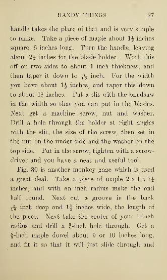
Fig. 30 is another monkey gage which is used
a great deal. Take a piece of maple 2 x 1 x 7\
inches, and with an inch radius make the end
half round. Next cut a groove in the back
T% inch deep and \\ inches wide, the length of
the piece. Next take the center of your 1-inch
radius and drill a f-inch hole through. Get a
f-inch maple dowel about 9 or 10 inches long,
and fit it so that it will just slide through and
28 PATTERNMAKING KINKS
not twist. Take a piece of tool steel about
5 x 16 inch diameter, and sharpen the same as
the other point. Put it through the dowel about
J inch from the end. Set in a loose shoe so that
it will just rest on the dowel. For length have
AFIG. 24
FIG. 25
FIG. 26 FIG.27
1
—
"D"^iFIG. 28
FIG. 29
Home Made Apprentice Tools.
it about J inch long, so as to make a groove to
keep it from sliding in and out when the arm is
moved. Set in a piece of brass about T^ inch
PATTERN SHOP WRINKLES 29
square, T\ inch thick, just above the shoe, which,
by the way. should be made of boxwood or
lignum-vit se. Xext get a thumb-screw long
enough to set down on the shoe. Drill a hole
through the top end of the upright as far as the
shoe, then tap for the same thread as the screw.
This makes a very useful gage where you have
to scribe a line OA~er a bead or other upward
projection.
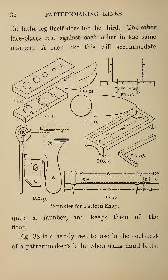
PATTERN SHOP WRINKLES
Figs. 31, 32 and 33 show methods of making
dowel rods. In Fig. 31 there is simply an iron
or steel block with holes, and the sticks, sawed
and planed approximately to size, are driven
through with a hammer. Fig. 32 is a piece of
j-inch thick tool steel with lips filed out as
shown, and then hardened. The wood pieces
are held by one end in a chuck in the lathe, and
the steel is held in the hand and pushed against
the dowel stick. This is an improvement on
Fig. 31, but not equal to Fig. 33. This latter
shows a casting A which answers for any given
30 PATTERNMAKING KINKS
size dowel by having the hole B drilled through
it 3L- inch larger in diameter, for clearance, than
the size of the work required. But one cutter,
C, is needed for a whole set of these holders.
The cutter has a slot D through which passes a
screw, thus holding it in place on the handle.
The holder A is countersunk at E enough to
start square sticks easily, and the cutter must be
adjusted by trial until the dowel comes out the
exact size required. It will be seen that the
knife is not flat, but angular, and the cutting is
done by the edge F, which is ground so as to be
slightly in advance. To operate, have the stick
previously sawed square about ^ inch larger
than the finished dowel, and hold one end in the
lathe. This is easily done by putting a block on
the screw chuck, and making a square hole in
the center to admit the sticks. Hold the cutting
tool in the right hand, and push firmly against
the stick as it is revolved by the lathe. This
simple tool will be found to make very good
dowel rods quite rapidly.
Fig. 34 is but a block of wood to hold in the
vise when clamping wedge-shaped or tapering
PATTERN SHOP WRINKLES 31
pieces of any kind. It can also be used against
a curved piece of work, if the radius of the curve
on block is less than that of the other. On
straight work that has a taper, simply place it
in the vise with the flat side of the block against
the piece. The round part makes a contact with
the jaw of the vise at the proper point without
further thought, and the work is held easily and
firmly.
Fig. 35 is a wood cone to fit the screw chuck
in the lathe, and is covered with emery to use in
sharpening gouges. These are commonly made
with a straight taper, but, by making them
something of a cartridge shape, like the figure, a
slight concave is given to the tool while grinding.
Fig. 36 shows an improvised pair of calipers
for heavy work, made by placing two large squares
together. They can be held firmly by two small
hand-screws, as indicated.
Fig. 37 is a rack to place beneath the pattern-
maker's lathe. It should stand on the floor next
the leg, and is to hold face-plates of all ordinary
sizes. The first face-plate stands crossways of
the rack, having two bearing points here, and
32 PATTERNMAKING KINKS
the lathe leg itself does for the third. The other
face-plates rest against each other in the same
manner. A rack like this will accommodate
Wrinkles for Pattern Shop.
quite a number, and keeps them off the
floor.
Fig. 38 is a handy rest to use in the tool-post
of a patternmaker's lathe when using hand tools.
GAGE FOR A BUZZ PLANER 33
On many jobs the angle increases its usefulness
to a large extent.
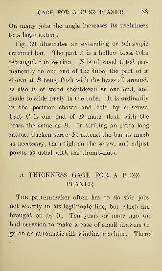
Fig. 39 illustrates an extending or telescopic
trammel bar. The part A is a hollow brass tube
rectangular in section. E is of wood fitted per-
manently to one end of the tube, the part of it
shown at B being flush with the brass all around.
D also is of wood shouldered at one end, and
made to slide freely in the tube. It is ordinarily
in the position shown and held by a screw.
Part C is one end of D made flush with the
brass the same as B. In striking an extra long
radius, slacken screw F, extend the bar as much
as necessary, then tighten the screw, and adjust
points as usual with the thumb-nuts.
A THICKNESS GAGE FOR A BUZZPLANER
The patternmaker often has to do side jobs
not exactly in his legitimate line, but which are
brought on by it. Ten years or more ago we
had occasion to make a case of small drawers to
go on an automatic silk-winding machine. There
34 PATTERNMAKING KINKS
were quite a number of these drawers to be
made, and f-inch stuff was called for on the case
and all. As there was no cylinder — or dimen-
sion— planer in the shop, the only one being a
buzz planer, we saw that the circular saw was to
be followed by a large amount of tedious hand
planing, and the thought kept revolving in the
mind as to whether there was not some possible
way in which the pieces could be brought to aN
thickness on the buzz planer.
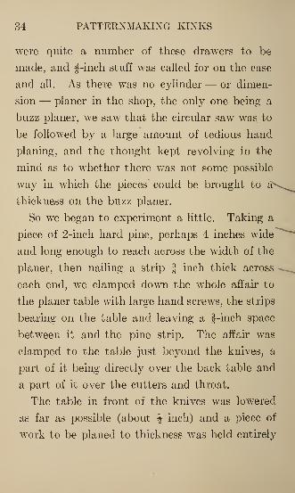
So we began to experiment a little. Taking a
piece of 2-inch hard pine, perhaps 4 inches wide
and long enough to reach across the width of the
planer, then nailing a strip f inch thick across •
each end, we clamped down the whole affair to
the planer table with large hand screws, the strips
bearing on the table and leaving a f-inch space
between it and the pine strip. The affair was
clamped to the table just beyond the knives, a
part of it being directly over the back table and
a part of it over the cutters and throat.
The table in front of the knives was lowered
as far as possible (about J inch) and a piece of
work to be planed to thickness was held entirely
GAGE FOR A BUZZ PLANER 35
away from this, but firmly under the edge of the
hard pine bridge above, and pushed ahead until
the end had passed the knives and rested on
the back table. Then trouble began. The piece
would stick and object to going ahead. It was
found necessary to cut away clearance on the
under side of the bridge strip, leaving but a
narrow portion of it, the given f inch in hight,
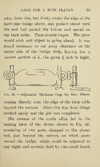
Fig. 40. — Adjustable Thickness Gage for Buzz Planer.
coming directly over the edge of the back table
beyond the cutters. After this was done things
worked nicely and the job was completed.
The success of the crude affair led to the
making later of the device shown in Fig. 40,
consisting of two posts clamped to the planer
bed, just beyond the cutters, on which posts
moved the bridge, which could be adjusted to
any hight and securely held by two small hand-
36 PATTERNMAKING KINKS
wheel tightening screws; the other two tightening
screws, which were used to clamp the posts, being
those ordinarily used to hold the fence in position.
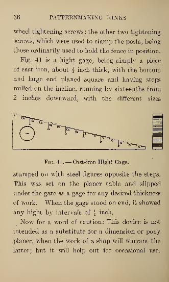
Fig. 41 is a hight gage, being simply a piece
of cast iron, about f inch thick, with the bottom
and large end planed square and having steps
milled on the incline, running by sixteenths from
2 inches downward, with the different sizes
Fig. 41. — Cast-iron Hight Gage.
stamped on with steel figures opposite the steps.
This was set on the planer table and slipped
under the gate as a gage for any desired thickness
of work. When the gage stood on end, it showed
any hight by intervals of J inch.
Now for a word of caution: This device is not
intended as a substitute for a dimension or pony,
planer, when the work of a shop will warrant the
latter; but it will help out for occasional use.
GAGE FOR A BUZZ PLANER 37
There is a knack in using it, and it may look a
little dangerous at first, but the one just described
was used as occasion required, for six or seven
years to our knowledge, and no one was ever
injured by it ; it is probably still in use.
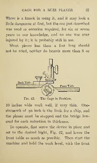
Short pieces less than a foot long should
not be tried, neither do boards more than 8 or
Fig. 42. — The Gage in Position.
10 inches wide work well, if very thin. One-
sixteenth of an inch is the limit for a chip, and
the planer must be stopped and the bridge low-
ered for each reduction in thickness.
To operate, first screw the device in place and
set to the desired hight, Fig. 42, and lower the
front table as much as possible. Then start the
machine and hold the work level, with the front
38 PATTERNMAKING KINKS
end of it firmly against the bottom of the gate
and push it ahead. It now passes the knives
and slides along the back table, and all the while
the piece is being planed it must be held with a
gentle pressure upward, so as at all times to be
in contact with the bridge; for if it is not, it will
be gouged into by the knives, and the work will
become uneven in thickness.
When the back end of the piece approaches
too near the cutters to be held safely, simply
grasp the part already passed and draw it
through. By this time there will not be enough
left in front of the knives to sag and cause the
trouble just referred to.
GAGES^R® PATTERNMAKING — FIXING
UP A CASTING FOR A PATTERN
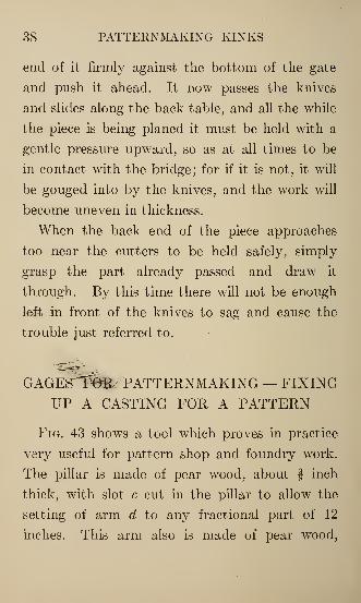
Fig. 43 shows a tool which proves in practice
very useful for pattern shop and foundry work.
The pillar is made of pear wood, about | inch
thick, with slot c cut in the pillar to allow the
setting of arm d to any fractional part of 12
inches. This arm also is made of pear wood,
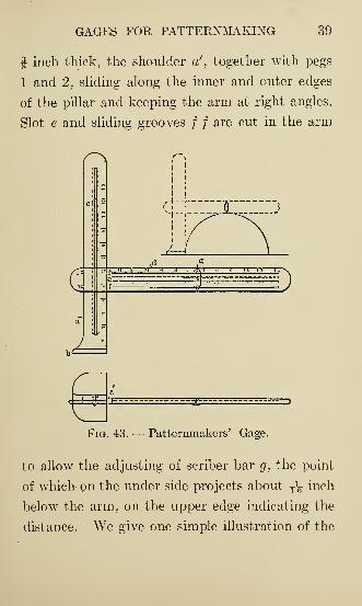
GAGES FOR PATTERNMAKING 39
f inch thick, the shoulder ae
, together with pegs
1 and 2, sliding along the inner and outer edges
of the pillar and keeping the arm at right angles.
Slot e and sliding grooves / / are cut in the arm
Fig. 43. — Patternmakers' Gage.
to allow the adjusting of scriber bar g, the point
of which on the under side projects about T\ inch
below the arm, on the upper edge indicating the
distance. We give one simple illustration of the
40 PATTERNMAKING KINKS
manipulation of this tool. It is required to mark
a center line along a 12-inch pipe pattern the
half of which is shown. The half pattern is
placed on the surface plate, the sliding bar and
scriber are fixed in position, the base is brought
in contact with the edge of the pattern and the
gage is then drawn along the pipe to the required
length.
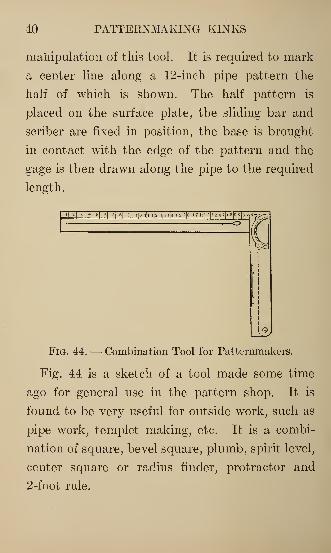
Fig. 44. — Combination Tool for Patternmakers.
Fig. 44 is a sketch of a tool made some time
ago for general use in the pattern shop. It is
found to be very useful for outside work, such as
pipe work, templet making, etc. It is a combi-
nation of square, bevel square, plumb, spirit level,
center square or radius finder, protractor and
2-foot rule.
GAGES FOR PATTERNMAKING 41
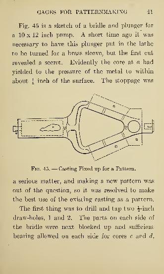
Fig. 45 is a sketch of a bridle and plunger for
a 10 x 12 inch pump. A short time ago it was
necessary to have this plunger put in the lathe
to be turned for a brass sleeve, but the first cut
revealed a secret. Evidently the core at a had
yielded to the pressure of the metal to within
about i inch of the surface. The stoppage was
Fig. 45. — Casting Fixed up for a Pattern.
a serious matter, and making a new pattern was
out of the question, so it was resolved to make
the best use of the existing casting as a pattern.
The first thing was to drill and tap twTo J-inch
draw-holes, 1 and 2. The parts on each side of
the bridle were next blocked up and sufficient
bearing allowed on each side for cores c and d,
42 PATTERNMAKING KINKS
as indicated by the dotted lines. The plunger
was next lagged with strips of wood, about
J inch in width and of the required thickness;
these were held in place with a couple of thin
wires. Drop print b was placed in position and
the pattern was ready. The casting produced
gave all satisfaction, and in less than thirty
hours' time the pump was again at work.
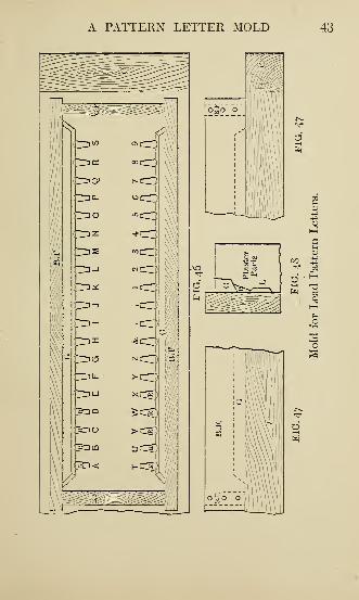
A PATTERN LETTER MOLD
Here is a sketch of a lead pattern letter mold.
In making the mold use good;clean-cut letters —
brass letters preferred. The wood part or mold
frame is made of cherry wood, and the mold of
sifted plaster of Paris. Make the frame good,
true and strong and you can have at any time on
short notice a mold that will turn out very
satisfactory lead letters. Don't ask an appren-
tice boy to make the mold frame or mold, but
when the mold is made you can keep him busy
pouring the molds and trimming letters.
In Fig. 47 A is a cherry board, 1 inch thick,
perfectly true on the letter face; C, a stiffener on
A PATTERN LETTER MOLD 43
44 PATTERNMAKING KINKS
the end. Shellac A and then put the letters on
in the usual way. B F is & box frame, the sides
about J inch from the edges of the letters and
1 inch deep. R R R are runners from gates G to
the letters. ' Cut the runners in with a chisel
after the mold is made, about T\ inch wide at
the gate, tapering and just large enough at the
letter to allow the mold to fill without chilling.
If the mold does not fill, the cause is that the
runner is not large enough. Place a piece of
wood, as in Fig. 48, tight to the face of the mold
and pour in melted lead, then shake out and
trim. To melt the lead use a large spoon and
heat with an alcohol lamp, placing small pieces
of lead in the spoon. A little frame to hold
spoon and lamp can be made and kept for the
purpose. If the lead does not melt fast enough,
put a small piece of wax in the spoon. After the
lead is melted skim off the dross and then pour.
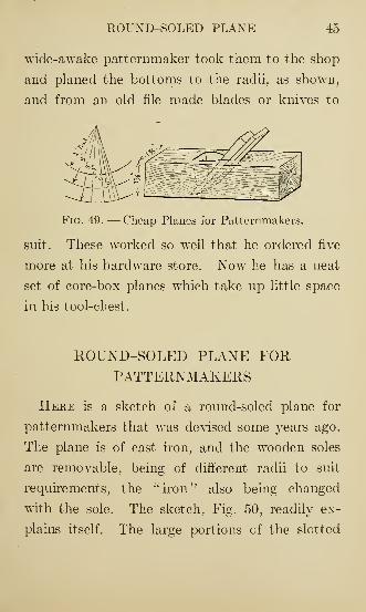
SMALL PLANES FOR PATTERNMAKERS
Having run across a number of small planes
of the dimensions shown in sketch, Fig. 49, a
ROUXD-SOLED PLAXE 45
wide-awake patternmaker took them to the shop
and planed the bottoms to the radii, as shown,
and from an old file made blades or knives to
4*!
Fig. 49. — Cheap Planes for Patternmakers.
suit. These worked so well that he ordered five
more at his hardware store. Now he has a neat
set of core-box planes which take up little space
in his tool-chest.
ROUND-SOLED PLANE FORPATTERNMAKERS
Here is a sketch of a round-soled plane for
patternmakers that was devised some years ago.
The plane is of cast iron, and the wooden soles
are removable, being of different radii to suit
requirements, the "iron" also being changed
with the sole. The sketch, Fig. 50, readily ex-
plains itself. The large portions cf the slotted
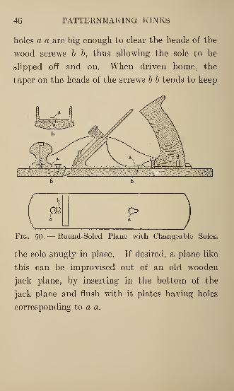
46 PATTERNMAKING KINKS
holes a a are big enough to clear the heads of the
wood screws b b, thus allowing the sole to be
slipped off and on. When driven home, the
taper on the heads of the screws b b tends to keep
pFig. 50. — Round-Soled Plane with Changeable Soles.
the sole snugly in place. If desired, a plane like
this can be improvised out of an old wooden
jack plane, by inserting in the bottom of the
jack plane and flush with it plates having holes
corresponding to a a.
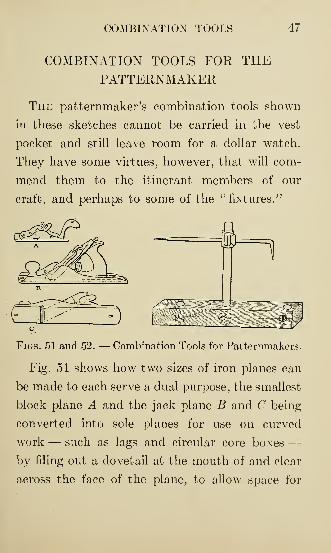
COMBINATION TOOLS 47
COMBINATION TOOLS FOR THEPATTERNMAKER
The patternmaker's combination tools shown
in these sketches cannot be carried in the vest
pocket and still leave room for a dollar watch.
They have some virtues, however, that will com-
mend them to the itinerant members of our
craft, and perhaps to some of the "fixtures."
Figs. 51 and 52. — Combination Tools for Patternmakers.
Fig. 51 shows how two sizes of iron planes can
be made to each serve a dual purpose, the smallest
block plane A and the jack plane B and C being-
converted into sole planes for use on curved
work — such as lags and circular core boxes —by filing out a dovetail at the mouth of and clear
across the face of the plane, to allow space for
48 PATTERNMAKING KINKS
the shavings to pass freely when used as a sole
plane. It will be found that the angle of the
plane iron makes it necessary to provide addi-
tional room, hence the width of the dovetail is
determined by the thickness of the soles used,
which should never be more than § inch on the
jack plane and T5g inch on the block plane of the
size shown. At C is shown the dovetail fitted
with a piece of cast iron or steel so that the
plane can be used as originally intended. The
" tadpole" holes shown at the ends, and used to
fasten the soles to the body through the medium
of button-head screws, are not of sufficient size
to cause trouble when "jacking" stock. In
making the soles, leave enough stock at the ends
so that after fitting to match the tadpole holes,
lines can be scribed to conform to the shape of
the plane outside, and to the width and length
of the mouth inside.
Fig. 52 shows a tool that also is a space saver,
as it can be used as a surface gage, straddle gage,
depth gage for lathe work, panel gage and router.
The body or base is made of hardwood 7\ x 2 x 1
inches, with three J-inch holes drilled through,
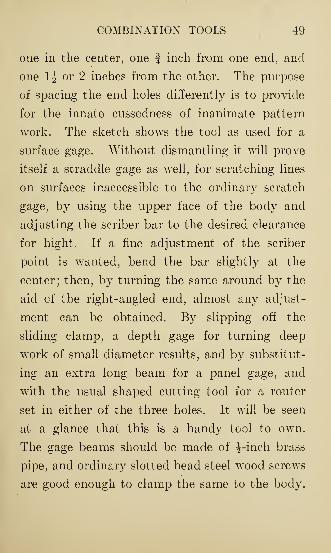
COMBINATION TOOLS 49
one in the center, one | inch from one end, and
one 1^ or 2 inches from the other. The purpose
of spacing the end holes differently is to provide
for the innate cussedness of inanimate pattern
work. The sketch shows the tool as used for a
surface gage. Without dismantling it will prove
itself a straddle gage as well, for scratching lines
on surfaces inaccessible to the ordinary scratch
gage, by using the upper face of the body and
adjusting the scriber bar to the desired clearance
for hight. If a fine adjustment of the scriber
point is wanted, bend the bar slightly at the
center; then, by turning the same around by the
aid of the right-angled end, almost any adjust-
ment can be obtained. By slipping off the
sliding clamp, a depth gage for turning deep
work of small diameter results, and by substitut-
ing an extra long beam for a panel gage, and
with the usual shaped cutting tool for a router
set in either of the three holes. It will be seen
at a glance that this is a handy tool to own.
The gage beams should be made of J-ineh brass
pipe, and ordinary slotted head steel wood screws
are good enough to clamp the same to the body.
50 PATTERNMAKING KINKS
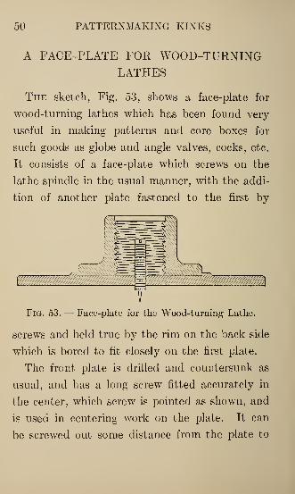
A FACE-PLATE FOR WOOD-TURNINGLATHES
The sketch, Fig. 53, shows a face-plate for
wood-turning lathes which has been found very
useful in making patterns and core boxes for
such goods as globe and angle valves, cocks, etc.
It consists of a face-plate which screws on the
lathe spindle in the usual manner, with the addi-
tion of another plate fastened to the first by
Fig. 53. — Face-plate for the Wood-turning Lathe.
screws and held true by the rim on the back side
which is bored to fit closely on the first plate.
The front plate is drilled and countersunk as
usual, and has a long screw fitted accurately in
the center, which screw is pointed as shown, and
is used in centering work on the plate. It can
be screwed out some distance from the plate to
PATTERN PLUG CUTTER 51
center pieces from their center lines. The outer
plate can also be removed and small work be
centered to it much more accurately than is
possible with the ordinary face-plate.
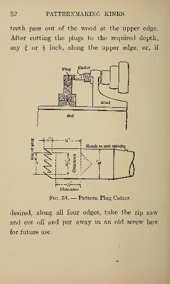
PATTERN PLUG CUTTER
When patterns are put together with screws
the heads being sunk in to allow for plugging
with wood plugs. Fig. 54 shows a plug cutter
and method of using it.
The cutter can be made of a straight piece of
tool steel to be held in the chuck, or the shank
can be made taper to fit the hole in the lathe
spindle. Some patternmakers attempt to cut
plugs from any old place on the face of the board
without any thought as to clearance for cuttings
or sawdust; this is a mistake. Rip a piece A,
about 1| inches thick, 3 inches wide and any
convenient length, and place this on block B
which rests on the bed of the lathe and is high
enough so that the top edge of A will be in line
with the hole in the cutter; this provides a
clearance so that sawdust may fly off when the
52 PATTERNMAKING KINKS
teeth pass out of the wood at the upper edge.
After cutting the plugs to the required depth,
say | or J inch, along the upper edge, or, if
-4-./^ a?—>j
Shank to suit spindle
Fig. 54. — Pattern Plug Cutter.
desired, along all four edges, take the rip saw
and cut off and put away in an old screw box
for future use.
A SHAVING BOX
A SHAVING BOX
53
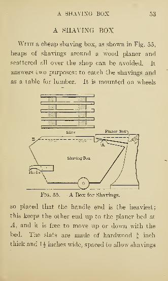
With a cheap shaving box, as shown in Fig. 5o,
heaps of shavings around a wood planer and
scattered all over the shop can be avoided. It
answers two purposes: to catch the shavings and
as a table for lumber. It is mounted on wheels
Fig. 55. — A Box for Shavings.
so placed that the handle end is the heaviest;
this keeps the other end up to the planer bed at
A, and it is free to move up or down with the
bed. The slats are made of hardwood § inch
thick and 1^ inches wide, spaced to allow shavings
54 PATTERNMAKING KINKS
to drop through and leaving an opening at B
for shavings scraped along with the lumber.
When sweeping up the shop the slats can be
removed and the sweepings can be put in the
box and carted away.
FRICTION DRIVE FOR A BAND-SAW
In the pattern shop or in any wood-working
shop where a band-saw is used, the starting and
stopping;or in other words the shifting of the
belt, is a nuisance and is laborious, par-
ticularly when this is _done several times each
day.
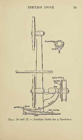
Fig. 56 shows a change made on an old
band-saw for the sake of an experiment, which
gave good results. The tight and loose pulleys
were removed and in their place put a sliding
friction disk and loose pulley. The disk was
shifted by a lever under which was a flat spring,
the spring being powerful enough to force the
leather face disk into contact with the pulley,
thus driving the saw. The disk was kept out of
contact when not in use by a hook at the front
FRICTION DRIVE 55
Base
Figs. 56 and 57. — Friction Drive for a Band-saw
56 PATTERNMAKING KINKS
of the machine; a downward pressure and side
movement of the foot releases the lever and
allows the spring to act at once.
Fig. 57 shows the yoke end of the lever fitting
over the hub of the disk. This ought to interest
band-saw manufacturers.
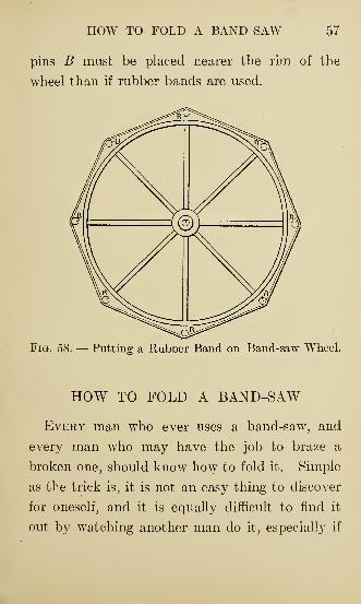
PUTTING A RUBBER BAND ON ABAND-SAW WHEEL
The following directions for putting a rubber
band on a band-saw wheel may be of interest to
some. First drive a hardwood pin A, Fig. 58, the
size of the hole in the wheel, into the bench.
Fit the f-inch pins B into the bench outside the
rim of the wheel. Cover the rim of the wheel
and the inside of the band with Le Page's glue,
shellac or sticky varnish. Stretch the band
evenly over the pins B, then draw them out,
letting the band back to the rim of the wheel.
Now take a piece of round steel of small diameter,
like a carpenter's scratch awl, and draw it around
between the band and rim. Let the wheel stand
over night. If canvas-back bands are used, the
HOW TO FOLD A BAND-SAW 57
pins B must be placed nearer the rim of the
wheel than if rubber bands are used.
Fig. 58. — Putting a Rubber Band on Band-saw Wheel.
HOW TO FOLD A BAND-SAW
Every man who ever uses a band-saw, and
every man who may have the job to braze a
broken one, should know how to fold it. Simple
as the trick is, it is not an easy thing to discover
for oneself, and it is equally difficult to find it
out by watching another man do it, especially if
58 PATTERNMAKING KINKS
he wishes to mystify the one who is watching
him. There is nothing equal to a practical
demonstration for explaining things of this sort,
but we have tried here to make it as clear as
possible with a number of illustrations, and with
these and a band-saw to practise with the trick
should be mastered in a few minutes.
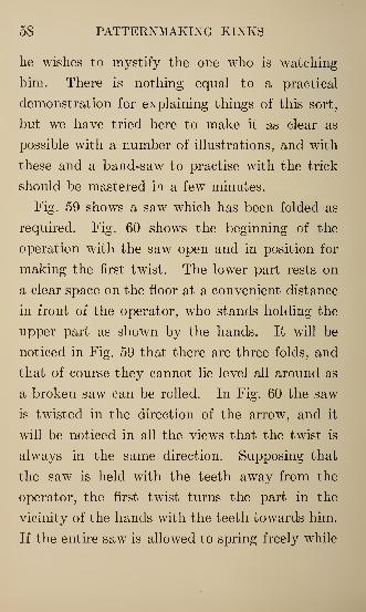
Fig. 59 shows a saw which has been folded as
required. Fig. 60 shows the beginning of the
operation with the saw open and in position for
making the first twist. The lower part rests on
a clear space on the floor at a convenient distance
in front of the operator, who stands holding the
upper part as shown by the hands. It will be
noticed in Fig. 59 that there are three folds, and
that of course they cannot lie level all around as
a broken saw can be rolled. In Fig. 60 the saw
is twisted in the direction of the arrow, and it
will be noticed in all the views that the twist is
always in the same direction. Supposing that
the saw is held with the teeth away from the
operator, the first twist turns the part in the
vicinity of the hands with the teeth towards him.
If the entire saw is allowed to spring freely while
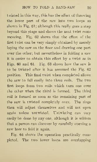
HOW TO FOLD A BAND-SAW 59
twisted in this way, this has the effect of throwing
the lower part of the saw into two loops as
shown in Fig. 61; although this really goes a step
beyond this stage and shows the next twist com-
mencing. Fig. 62 shows that the effect of the
first twist can be very simply obtained by merely
laying the saw on the floor and drawing one part
over the other; but nevertheless in folding a saw
it is easier to obtain this effect by a twist as in
Figs. 60 and 61. Fig. 63 shows how the saw is
to be twisted after it has assumed the Fig. 62
position. This final twist when completed allows
the saw to fall easily into three coils. The two
first loops form two coils which turn one over
the other when the third is formed. The third
coil is formed as soon as the remaining part of
the saw is twisted completely over. The rings
then will adjust themselves and will not open
again unless untwisted. Untwisting can very
easily be done by any one, although it is seldom
that a person can discover by carefully opening a
saw how to fold it again. .
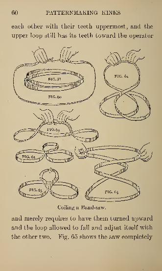
Fig. 64 shows the operation practically com-
pleted. The two lower loops are overlapping
60 PATTERNMAKING KINKS
each other with their teeth uppermost, and the
upper loop still has its teeth toward the operator
Coiling a Band-saw.
and merely requires to have them turned upward
and the loop allowed to fall and adjust itself with
the other two. Fig. 65 shows the saw completely
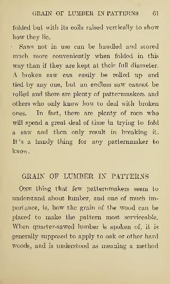
GRAIN OF LUMBER IN PATTERNS 61
folded but with its coils raised vertically to show
how they lie.
1 Saws not in use can be handled and stored
much more conveniently when folded in this
way than if they are kept at their full diameter.
A broken saw can easily be rolled up and
tied by any one, but an endless saw cannot be
rolled and there are plenty of patternmakers and
others who only know how to deal with broken
ones. In fact, there are plenty of men who
will spend a great deal of time in trying to fold
a saw and then only result in breaking it.
It's a handy thing for any patternmaker to
know.
GRAIN OF LUMBER IN PATTERNS
One thing that few patternmakers seem to
understand about lumber, and one of much im-
portance, is, how the grain of the wood can be
placed to make the pattern most serviceable.
When quarter-sawed lumber is spoken of, it is
generally supposed to apply to oak or other hard
woods, and is understood as meaning a method
62 PATTERNMAKING KINKS
only of showing the markings on the face of the
board.
But there are quarter-sawed boards in pine
or any other kind of lumber. A quarter-sawed
board is one that is cut from the log radially,
as in Fig. 66. To cut all boards quarter-sawed
would waste too much of the log, which is the
reason that only a few boards from each log are
sawed radially.
A quarter-sawed board will stay practically
straight during many changes of temperature or
humidity. So if you have a thin pattern to make
that has no ribs to hold it straight, select, if
possible, a quarter-sawed piece, which can be
easily done by looking at the grain on the end.
You may waste a little stock to get such a piece,
but just consider the convenience of having the
pattern stay the way it was made. We remem-
ber an instance of making new patterns to replace
some that were badly warped. Cleats were or-
dered put on the new patterns, to be afterwards
stopped off. The patterns were sent to the
foundry without cleats, with word that when
they became crooked, to send them back and we
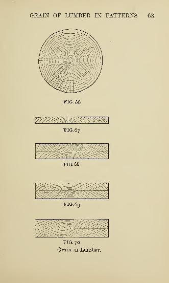
GRAIN OF LUMBER IN PATTERNS 63
FIG. 66
^^^FIG. 67
mmmFIG. 68
FIG. 69
FIG. 70
Grain in Lumber.
64 PATTERNMAKING KINKS
would put the cleats on. But we never saw them-
again.
A board like Fig. 67 will not stay straight
long — which reminds us of the boy who tried to
plane such a piece straight; the more he planed
the worse it got, until it began to look as if there
would be no board left. The boss told him he
didn't plane fast enough to keep ahead of the
warping.
When gluing two thicknesses together, it is
better to place them so that the grain will lie
as in Fig. 68, because the warp of one piece will
counteract that of the other, and the joint will
not open as readily on the edges as if placed like
Fig. 69 or 70.
If you glue one piece across another you will
get the effect of Fig. 71, unless the glue lets go
or one piece splits in shrinking. The pull of
board A in shrinking is often powerful enough to
bend board B in its length. Cross grain is only
effective with absolutely dry material of four or
more thicknesses.
A pattern like Fig. 72 is more serviceable if
made with the length cf the bottom piece running
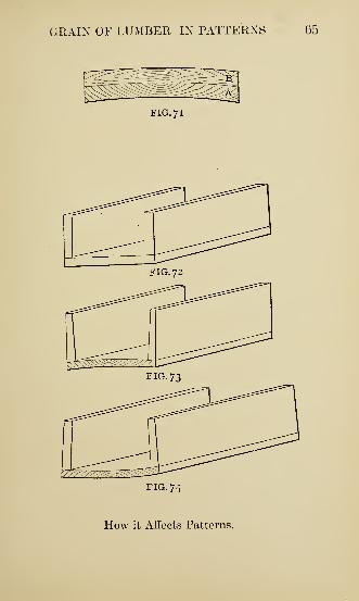
GRAIN OF LUMBER IN PATTERNS 65
§« -B'"
FIG. 7
1
FIG. 74
How it Affects Patterns.
66 PATTERNMAKING KINKS
from one rib to the other, as the bottom will stay
straight and the ribs will always draw. If made
like Fig. 73 or 74 you get the effect shown,
which will distort the ribs so that the pattern
will not draw.
If the grain of the wood can be put in pattern
in the same direction as the line of draft, a slight
warping will not affect the drawing of the pat-
tern. This cannot always be clone, because
patterns so made would be weak in vital parts.
Distribution of the grain of wood in patterns is
as much a study as the distribution of metal,
both equally affecting the utility of their respec-
tive constructions.
JUDGMENT IN PARTING PATTERNS
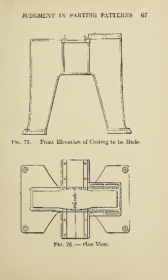
Figs. 75, 76 and 77 show three views of a
machine frame to be cast. It is about 30 inches
high, which will give a sufficient idea of the sizes.
The common way to part symmetrical work is
along the axis of symmetry, and this does very
well with rectangular sections up to a certain
size, and up to any size with circular sections.
JUDGMENT IN PARTING PATTERNS 67
Fig. 75. — Front Elevation of Casting to be Made.
©
©
©.
M7-—)C^TP
©J
Fig. 76. — Plan View.
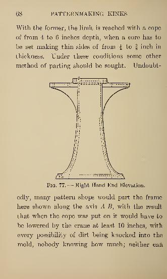
68 PATTERNMAKING KINKS
With the former, the limit is reached with a cope
of from 4 to 6 inches depth, when a core has to
be set making thin sides of from \ to | inch in
thickness. Under these conditions some other
method of parting should be sought. Undoubt-
Fig. 77. — Right Hand End Elevation.
edly, many pattern shops would part the frame
here shown along the axis A B, with the result
that when the cope was put on it would have to
be lowered by the crane at least 10 inches, with
every possibility of dirt being knocked into the
mold, nobody knowing how much; neither can
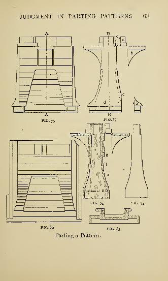
JUDGMENT IN PARTING PATTERNS 69
FIG, 80 FIG. 83
Parting a Pattern.
70 PATTERNMAKING KINKS
the thickness of metal left on either side of the
core be known.
Figs. 78 and 79 show the pattern as built to
help the molder. The parting line is along c c c c,
with the pieces a, b, e loose and molded in the
cope. A half-core box, of which Fig. 80 is a
plan, was made covering d with separate boxes
for a and the corresponding parts of the nowel.
After the pattern is drawn the small cores in the
nowel are set, then the main core; any dirt which
may be accidentally knocked into the nowel can
now be easily removed, the thickness of metal on
the sides may be observed and the thickness of
stock above the core determined without putting
on the cope. The cores for a are hung in the
cope.
This construction is open to the criticism of
entailing additional loose pieces, with their at-
tendant troubles; but the certainty of clean
castings of uniform thickness justifies the extra
care necessary in keeping account of these pieces.
The anatomy of this pattern is shown pretty
clearly by Figs. 81 and 82. Pieces like Fig. 82
were first got out, and to them were nailed e, /, g,
FILLETING WOODEN PATTERNS 71
etc. These e, /, g were also glued and nailed to
each other, as they were built up. It will be
noted that all stock is so attached that the
pattern draws with the grain of the wood.
Another source of much trouble is not having
castings come to size in the improper and insuffi-
cient means by which loose pieces are often
attached to the main part of the pattern. Werecently had a pattern sent to our foundry by a
customer a section of which was like Fig. 83,
with the pieces k loose and without dowel pins.
It must be evident that these pieces could not be
held in their proper places without pins. Could
every patternmaker spend six months in the
foundry many of these little oversights would be
avoided and much trouble would be saved for all
concerned.
FILLETING WOODEN PATTERNS
It would be difficult, perhaps, to find anything
like unanimity of opinion among patternmakers
regarding the real value of the fillet. Still this
much may be affirmed without hesitation, that
72 PATTERNMAKING KINKS
the majority believe in and make free use of it in
their work. In well-nigh every reputable shop a
piece of work would hardly be looked upon as
finished if the corners were left unfilled; and
certainly only a slouchy, careless workman would
allow a pattern to leave his hands in such condi-
tion.
Many reasons may be assigned for this time-
honored practice, but the main one is that it is
a great accommodation to the molder, and also
ensures a cleaner and more finished casting.
Leave the corners of a pattern unfilled and the
chances are that the sharp corners of sand become
ragged, resulting very often in rough and un-
sightly castings. It is always best to fill in the
corners, unless there be some special reason, as
sometimes is the case, for not doing so. It may
be added also that sometimes the fillet is used for
strengthening purposes. The addition of more
metal in the corners, be it ever so small, greatly
increases the strength of a casting. Every ex-
perienced patternmaker can testify to the im-
portance of the fillet in this particular.
For all straight surfaces the wooden fillet
FILLETING WOODEN PATTERNS 73
answers the purpose very well, providing one
has nothing better at hand. It is very annoying,
however, when a person is in a great hurry to
finish a job, to be compelled to turn aside and
sometimes spend considerable time in making
fillets. Then one is tempted to wish that he
could buy a stock of ready-made fillets, and thus
obviate both the annoyance and the delay.
To meet this long-felt want, and at the same
time do away with the inconvenience, different
kinds of filleting material have been placed on
the market, notably the lead and the leather
fillet. The former has never met with a kind
reception because it gives too much trouble in
tacking, does not lie closely to the wood and
rarely makes what is called a finished job. The
latter, on the other hand, has met with hearty
approval as the best thing of its kind in the
market. It can be easily adjusted to any kind
of surface, curved as well as straight, is easily
fastened to the wood by either shellac or thin
glue, adds to the strength and gives a finished
appearance to the pattern. In fact, when the
surface is shellacked, it affords a mahogany effect.
74 PATTERNMAKING KINKS
On curved surfaces it lies as snugly and smoothly
as on straight. And considering the moderate
cost of this new device, together with the great
saving of time which its use secures, it certainly
pays to keep a good supply of it always on
hand.
If we dared venture to recommend the best
filleting material for constant use in all kinds of
pattern work, we would give preference to the
leather kind.
How to Apply Them
Leather fillets are not new, but how to apply
them so that they will stick for keeps is sometimes
a problem. Some advocate the use of shellac or
thin glue, which is at least safe advice, considering
the fact that most patternmakers have not free
access to the jealously guarded office mucilage
bottle.
Wood fillets, if for use in right-angled corners,
should be planed to 93 degrees angle, and are
so made and sold, and if a real good job is desired,
put the filleting in a fillet board and curl over the
edges by sandpapering with a cylinder somewhat
FILLETING WOODEN PATTERNS 75
larger in diameter than twice the radius of the
fillet. By adopting this little kink very little
rubbing is necessary, provided good, stiff glue is
used immediately after moistening the outer
edges only, and it will be found that, when per-
fectly dry, the edges are there to stay and without
exposing the usual irregular streaks and patches
of glue at that.
As to leather fillets, there is only one way to
fasten them properly, and that's with glue.
After dampening the outside, not too much, and
spreading the glue as evenly as possible, get to
work with your little steel ball p. d. q. until
everything is lovely.
And now just a few "don'ts" on this question:
Don't saturate a leather fillet with water from
the grindstone keg before gluing.
Don't saturate a leather fillet with water from
the glue pot after gluing.
Don't slobber glue on a fillet; enough is a
genteel sufficiency.
Don't ever use shellac on a fillet; it's a waste
of good material.
Don't ever use lead fillets with the idea that
76 PATTERNMAKING KINKS
they are the ancestors of the "lead pipe cinch"
family; it is not so.
" X-RAY" PATTERN WORK
The men in the shop called it the "X-ray"
trick. We were making a number of pulleys with
five, six or seven arms. Each pattern was made
in halves for the molding machine, only one half
pattern was made, and this had to be very accu-
rate, so as to reverse. We made the pattern as
nearly as possible correct, but the foreman had a
slight doubt about it, and he told us to lay it
on a piece of drawing paper and cut out the arms
and see if it would reverse. We did this with a
number of them and found it a great lot of
trouble to get the paper arms cut out exact, and
when the cut paper was left over night it would
change its shape. Then we thought the thing
over to see if it could not be done some other
way. We took a piece of ordinary drawing paper,
placed it on a flat surface and then placed the
pulley on the paper and traced the arms and
rim. After tracing, the paper was taken to one
PATTERN REPAIRS—WAXING 77
of the windows and put up flat against the glass
and then the pulley pattern on the paper. In
this way we could do in two minutes what before
took a quarter to half an hour7and with far
better results. Now all match patterns are tried
in this way.
PATTERN REPAIRS — WAXING
Much time and considerable money are spent
every year in most establishments in pattern
repairs; a number of years spent in the pattern
shop of a large foundry have proved that to me
most effectually in one item at least, viz., the
waxing of patterns.
Where the vent wire has left its marks, and in
some cases mighty good sized ones, from constant
use, instead of wax use plaster of Paris; and if it
is applied in the proper way it will be found
more durable, cheaper and quicker to apply than
wax. Have the pattern brushed clean and apply
a light flowing coat of yellow shellac, which will
run in the holes and crevices, and allow it to dry.
Take a block of wood 5x5x2 inches thick, bore
78 PATTERNMAKING KINKS
a 2-inch hole 1J inches deep, and you have your
receptacle for holding and mixing your plaster.
Fill two-thirds with plaster, pour in your shellac
and mix until a thick paste is formed. It is now
ready to apply. Work well into all vent holes
and cracks, smooth all off, and allow 30 minutes
to 1 hour to dry. Sandpaper what projects above
the surface, and your pattern is ready for var-
nishing. You will be surprised at the finish and
durability of your pattern, besides a big item in
reduction of expense.
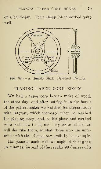
A QUICKLY MADE FLY-WHEEL PATTERN
We were asked to make a wheel of about the
design and dimensions as shown in sketch, Fig.
84. The man wanting the wheel did not wish
to expend much money on the pattern, as it was
only for an experiment and might not be used
again. For the rim we used lead pipe, which
was filled with sand and bent around an old
boiler shell; the spokes were made of 1-inch dowel
pins, laying in the mold pieces of 1-inch wrought
iron in their places, and the hub was sawed out
PLANING TAPER CORE BOXES 79
on a band-saw. For a cheap job it worked quite
well.
Fig. 84. — A Quickly Made Fly-wheel Pattern.
PLANING TAPER CORE BOXES
We had a taper core box to make of wood,
the other day, and after putting it in the hands
of the patternmaker we watched his preparations
with interest, which increased when he reached
the planing stage, and, as his plane and method
were both new to us, and may be to others, we
will describe them, so that those who are unfa-
miliar with the scheme may profit by his example.
His plane is made with an angle of 83 degrees
16 minutes, instead of the regular 90 degrees of a
80 PATTERNMAKING KINKS
right angle, and in practice he lays out the semi-
circle of the core box and the ends, and fastens
upon it, with brads, strips of hardwood having
straight edges upon the inside and touching the
points where the ends of the semicircle cut the
edges of the blank. The thickness of these strips
must be TV of an inch or fractional parts thereof
for each inch in diameter the core box is to be.
By this method he secures a finished core box,
with good sharp edges, which result is accurately
obtained without the use of templets or other
instruments. All the wear of the plane comes
upon the hardwood strips, which save the edges
of the core box from becoming rounded, and it is
especially of value in generating the surfaces of
taper core boxes, in which case he makes his
hardwood strips the same taper in sixteenths
which he wishes the core box to vary by in inches
of its diameter.
It is evident that any fractional basis may be
assumed which is most convenient for the work
generally handled, so that instead of adding guide
strips of a thickness in sixteenths equal to the
diameter in inches, they may be assumed of a
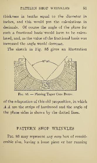
PATTERN SHOP WRINKLES 81
thickness in tenths equal to the diameter in
inches, and this would put the calculations in
decimals. Of course the angle of the plane for
such a fractional basis "would have to be calcu-
lated, and, as the value of the fractional basis was
increased the angle would decrease.
The sketch in Fig. 85 gives an illustration
Fig. 85. — Planing Taper Core Boxes.
of the adaptation of this old proposition, in which
A A are the strips of hardwood and the angle of
the plane sides is shown by the dotted lines.
PATTERN SHOP WRINKLES
Fig. 86 may represent any core box of consid-
erable size, having a loose piece or bar running
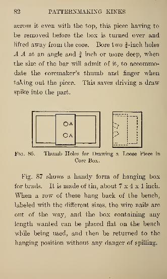
82 PATTERNMAKING KINKS
across it even with the top, this piece having to
be removed before the box is turned over and
lifted away from the core. Bore two f-inch holes
A A at an angle and f inch or more deep, when
the size of the bar will admit of it, to accommo-
date the coremaker's thumb and finger when
taking out the piece. This saves driving a draw
spike into the part.
OA
Ca > i
Fig. 86. — Thumb Holes for Drawing a Loose Piece in
Core Box.
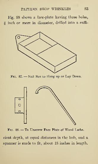
Fig. 87 shows a handy form of hanging box
for brads. It is made of tin, about 7x4x1 inch.
When a row of these hang back of the bench,
labeled with the different sizes, the wire nails are
out of the way, and the box containing any
length wanted can be placed flat on the bench
while being used, and then be returned to the
hanging position without any danger of spilling.
PATTERN SHOP WRINKLES 83
Fig. 88 shows a face-plate having three holes,
| inch or more in diameter, drilled into a suffi-
Fig. 87. — Nail Box to Hang up or Lay Down.
Fig. 88. — To Unscrew Face Plate of Wood Lathe.
cient depth, at equal distances in the hub, and a
spanner is made to fit, about 18 inches in length.
84 PATTERNMAKING KINKS
This is handy for removing, when a little too
tight to start by hand, and yet not "dead set/'
as we say.
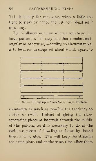
Fig. 89 illustrates a case where a web to go in a
large pattern, which may be either circular, rect-
angular or otherwise, according to circumstances,
is to be made in strips set about J inch apart, to
Fig. 89. — Gluing up a Web for a Large Pattern.
counteract as much as possible the tendency to
shrink or swell. Instead of gluing the short
separating pieces at intervals through the middle
of the pattern, as it is necessary to do at the
ends, use pieces of doweling as shown by dotted
lines, and no glue. This will keep the strips in
the same plane and at the same time allow them
PATTERN SHOP WRINKLES 85
their freedom if subjected to extremes of moisture
or dryness.
When a loose piece is used, it occasionally
happens that some means must be employed to
have it keep absolutely in its exact position while
being rammed, without any possibility of shifting,
as there is when wires are used to hold it; espe-
cially when the piece is long in proportion to its
bearing surface. Fig. 90 shows an idea sometimes
used in shops on a particular piece, for this
very purpose.
It consists of a clamp A and two plates B B,
Fig. 90, which can be round, square or rectangular,
according to circumstances. When the nature
of the work will admit of it, round ones are
preferable, for they fit a hole made by an extension
bit. The part d of clamp A is threaded a short
distance, and the length from end to shoulder
must be made to fit any particular case, being-
enough longer than the loose part on pattern, to
screw into the plate having the tapped hole; the
other plate has a drilled hole just the diameter of
d beyond the thread. The other portion of A is
of any convenient length. Sometimes it is made
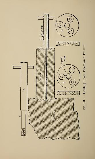
oo
g
PATTERN SHOP WRINKLES 87
long enough to stick through the outside of the
flask.
The section view in Fig. 90 shows the method
of using. One plate is screwed flush into the
pattern, and has a hole tapped to fit the key or
clamp. The other plate is screwed flush into the
loose part and has a plain hole. This hole is
continued through the loose piece. When the
clamp is screwed up, the shoulder binds against
the plate on the loose piece and presses it so firmly
against the pattern that no amount of ramming
will disturb its position, and when the sand is
thoroughly packed against the part it can be
easily unscrewed without disturbing anything.
This arrangement is, of course, intended to be
used only in special instances.
Fig. 91 is a block in which to rest a flat chisel
while turning a piece of some length to a given
diameter, if it is necessary to have it very smooth.
A patternmaker, when holding a pair of calipers
in one hand and a flat chisel in the other, gets a
scraping cut, but a little block like the cut causes
the chisel to lie at an angle and makes a smooth,
drawing cut. Chisel and block are to be held
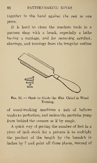
88 PATTERNMAKING KINKS
together in the hand against the rest as one
piece.
It is hard to clean the machine tools in a
pattern shop with a brush, especially a lathe
having a carriage, and for removing sawdust,
shavings, and turnings from the irregular outline
Sectionof
Block
Fig. 91. — Block to Guide the Flat Chisel in WoodTurning.
of wood-working machines a pair of bellows
works to perfection, and makes the particles jump
from behind the corners as if by magic.
A quick way of getting the number of feet in a
piece of inch stock for a pattern is to multiply
the product of the length by the breadth in
inches by 7 and point off three places, instead of
PATTERN SHOP WRINKLES 89
dividing by 144. This is not absolutely accurate,
but near enough for all practical purposes in
measuring small amounts.
For example, take a board 18 inches long and
8 inches wide: 18" X 8" -f- 144 = .1 square foot;
18" X 8" X 7 = 1.008 square feet. The error is
.008 of a foot when using the multiplier 7.
Again, take a board 7J feet by 16 inches:
90" X 16" ~ 144 = 10 square feet; 90" X 16 X 7
= 10.080 square feet. This time the error is ten
times as much, but still only .08 of a foot out of
the way in a 10-foot board.
When measuring thicker stock than 1 inch by
this method, multiply the length, breadth, and
thickness in inches together; then use 7 for a
multiplier, as before, pointing off three places.
In effect this method is expressed thus: Cubic
inches X .007 = square foot board measure.
In many shops the backs of all loose pieces are
painted red, and the corresponding place on the
pattern painted to match. When these loose
parts are circular in outline, with one wire or
wooden stick of doweling through the center to
hold them in place, the shape can be instantly
90 PATTERNMAKING KINKS
transferred to the pattern by first painting the
back of the loose piece, and, while it is still moist,
placing it in position on the pattern and turning
it around a few times with a light pressure. Even
if these round bosses do not bear fairly against
the pattern over their entire surface, if they
touch on the outer edge the shape is printed and
the center can be easily filled in without especial
care, but to follow a line exactly with a brush
without a rest for the hand is difficult for most
persons.
Sandpaper can be used for truing an oilstone
when emery cloth or loose sand is not handy, but
it works very poorly when dry. Place the sand-
paper on a board and keep it wet with water,
rubbing the stone vigorously at the same time.
The water seems to keep the sandpaper from
clogging up, and it cuts the stone much more
rapidly, but a single sheet will not last very long,
as the water loosens the sand and softens the
glue, so the stone must be washed off as soon as
ground true so that no glue may remain.
CIRCULAR PATTERN WORK 91
CIRCULAR PATTERN WORK
Many different shapes and sizes of circular
patterns may with advantage be prepared for
the molder's use by the method about to be
described. This method is of equal value as a
time-saver whether 6 or 1000 castings are wanted
from the pattern made. It has also the advan-
tage of providing directly for the molders 7
use a
pattern equal in every respect to a plate pattern,
and which may in many instances be worked by
comparatively unskilled labor. Fig. 92 is a plan
and section of a casting of which 1000 were
wanted. Fig. 93 shows section and plan of the
drag part of the pattern, which is prepared by
first truing up a suitable board and chucking the
same in the lathe. The convex side of the
pattern is fastened on to the board and turned
down so that the board serves as a joint when
used in the molding shop.
The pattern used to form the concave side or
top part of the mold is prepared similarly to the
drag, with the exception that the board is made
sufficiently thick to allow the contour of the
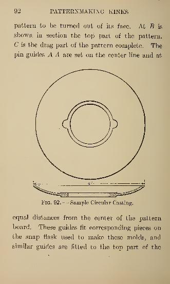
92 PATTERNMAKING KINKS
pattern to be turned out of its face. At B is
shown in section the top part of the pattern.
C is the drag part of the pattern complete. The
pin guides A A are set on the center line and at
Fig. 92. — Sample Circular Casting.
equal distances from the center of the pattern
board. These guides fit corresponding pieces on
the snap flask used to make these molds, and
similar guides are fitted to the top part of the
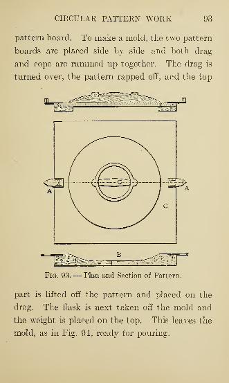
CIRCULAR PATTERN WORK 93
pattern board. To make a mold, the two pattern
boards are placed side by side and both drag
and cope are rammed up together. The drag is
turned over, the pattern rapped off, and the top
Fig. 93. — Plan and Section of Pattern.
part is lifted off the pattern and placed on the
drag. The flask is next taken off the mold and
the weight is placed on the top. This leaves the
mold, as in Fig. 94, ready for pouring.
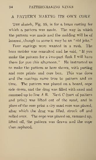
94 PATTERNMAKING KINKS
A PATTERN MAKING ITS OWN CORE
The sketch, Fig. 95, is for a brass casting for
which a pattern was made. The way in which
the pattern was made and the molding will be of
interest, though to some it may be an "old joke."
Four castings were wanted in a rush. The
boss, molder was consulted and he said, " If you
make the pattern for a two-part flask I will have
them for you this afternoon." He instructed us
to make the pattern as here shown, with parting
and core prints and core box. This was done
and the castings came true to pattern and on
time. The pattern was placed on a board, cope
side down, and the drag was filled with sand and
rammed up to line A B. Next C (part of pattern
and print) was lifted out of the sand, and in
place of the core print a dry sand core was placed,
after which the drag was filled, struck off and
rolled over. The cope was placed on, rammed up,
lifted off, the pattern was drawn and the cope
then replaced.
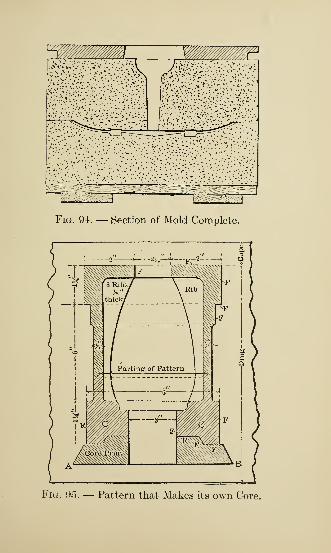
!:-->:; " ",.' :l
Fig. 94. — Section of Mold Complete.
Fig. 05. — Pattern that Makes its own Gore.
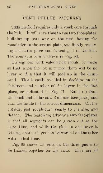
98 PATTERNMAKING KINKS
CONE PULLEY PATTERNS
This method requires only a stock core through
the hub. It will save time to use two face-plates,
building up part way on the first, having the
remainder on the second plate, and finally remov-
ing the latter piece and fastening it to the first.
The complete core is shown in Fig. 96.
On segment work calculation should be made
so that when the job is turned there will be no
layer so thin that it will peel up in the damp
sand. This is easily avoided by deciding on the
thickness and number of the layers in the first
place, as indicated in Fig. 97. Build up from
the small end as far as d d on one face-plate, and
turn the inside to the correct dimensions. On the
outside, just rough-turn nearly to the size, and
detach. The reason we advocate two face-plates
is that all segments can be gotten out at the
same time, and while the glue on one layer is
setting, another layer can be worked on the other
with no lost time.
Fig. 98 shows the cuts on the three pieces to
be framed together for the arms. They are all
CONE PULLEY PATTERNS 97
cut at an angle of 60 degrees with the edges of
the pieces and tangent to a circle of a diameter
equal to the width of the stock. Gage both edges
of each piece into three equal divisions, and
describe a circle in the center on both sides of Aand one side of B and C, then lay out the lines
tangent and make the cuts as indicated. B and
C are exactly alike. Have them fit loosely before
gluing, as," when tight joints are made, the pieces
B and C invariably spring outward from the
plane in which they should lie.
In order to get fillets on the ends of the arms,
cut them a little short, and then fasten on pieces
of hardwood, as shown in Fig. 100, with the grain
running in the opposite direction for strength.
By attaching the arms just mentioned to a small
face-plate not greater in diameter than the hub,
the taper of the spokes on both sides and the
fillet on the under side can be turned. Doing
this in the lathe insures all the arms being in the
same plane, so that they lie flat when in position.
Also square off the ends to the right diameter,
allowing at least | inch to fit the pockets to be
cut on the inside of the second step of the cone,
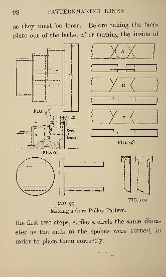
98 PATTERNMAKING KINKS
as they must be loose. Before taking the face-
plate out of the lathe, after turning the inside of
FIG. 99
Making a Core Pulley Pattern.
the first two steps, strike a circle the same diam-
eter as the ends of the spokes were turned, in
order to place them correctly.
CONE PULLEY PATTERNS 99
The outline of the spokes or arms previously
framed together should now be laid out and
sawed. Then place in position in the pulley,
and use it as a guide to mark the width of the
places to cut out. It is easy to cut them now,
before the last two steps are added. After they
are ready to receive the arms, glue on the last
two steps previously laid up on the second face-
plate, remembering to break joints, and set the
whole on a level surface, large end of cone down-
wards, and place a weight on the top of the face-
plate still adhering to the small end of the cone,
until the joint is set. In turning, observe the
draft in Fig. 97, somewhat exaggerated. The
inside of the small step is tapered the other way.
Two degrees taper on the inside of the steps and
one degree on the outside gives a very liberal
amount. The hub on the cope side (towards the
large end of the pulley) should be loose and fit
the arms with a standard size spindle or shank.
It is considered good practice on nearly all
kinds of pulleys of any size to make all hubs
interchangeable and to have a standard sized hole
through the center of the web or arms, as the
tore,
100 PATTERNMAKING KINKS
case may be, to fit the shank on the hubs, and
also a hole in the hubs themselves, to accom-
modate different core prints. Some shops have
1J inches as a standard for the spindle or shank
on all hubs, and f inch for all core prints. Some
standard should be employed, as it is so great an
aid in changing core prints and hubs to accom-
modate different conditions.
To facilitate molding, saw out a round piece of
board and nail a couple of strips to it, as in Fig. 99,
making the hight equal to X on the cone. The
cone is set on the mold board, large end down-
ward, with the arms removed, and the piece Kinside, reaching a a, Fig. 97. Then the nowel is
rammed, after which turn the flask, remove K,
and complete the ramming. The next parting
will be on a level with the spokes, and this section
of sand has to be lifted with a crab.
The cope extends downwards as far as the
spokes, and meets the division of sand just men-
tioned. The loose hub comes up with the cope;
then the spokes holding the nowel hub can be
drawn, next the sand cake on the crab, and lastly
the pattern itself.
MAKING CAM PATTERNS 101
MAKING CAM PATTERNS
Having been at one time in a locality where
great numbers of cam patterns were made for
automatic machinery, such as wire-forming ma-
chines, hook machines, etc., where in some
instances quite a large number of cams would be
needed on the same machine, all varying some-
what but each of the same general type, we will
attempt to describe the practice as there em-
ployed.
Fig. 101 illustrates the style of cam referred to,
often called a face cam. When not over a foot
in diameter these patterns are of simple construc-
tion, nothing being done, in the way of narrow
strips or segments, to prevent warping and shrink-
ing; for the castings are machined all over or very
nearly so, and a liberal finish is left on the
patterns.
Each pattern consists of three pieces of wood
until after the lathe work is done: one for the
hub and two for the body. The disks for the
bodies are band-sawed from the plank and planed
102 PATTERNMAKING KINKS
on one side on the buzz planer. The disk a,
Fig. 101, is attached to the face-plate, and faced
off to x y. Then disk b is screwed to a, and
both pieces are turned as one. The hub c is of
course separate, recessed into b, making a loose
piece as it is cast in the cope. A templet, cut
with scissors from very thin metal known as
"button covering," accompanies the drawing and
is the exact outline of the inner edge of the cam
groove. This templet later goes into the machine
shop, and is used there in laying out the shape on
the blank former which goes in the cam-cutting
machine. The patternmaker places the templet
in the right position on the face of the blank just
turned, and holds it with a few fine wire brads.
Wherever in the templet outline there is an arc
of a true circle, the fine center point is still
visible which was used in laying it out. This
now comes in play as the position for the divider
leg. The dividers are set, leaving a radius at
least J inch greater for finish for the inner curves,
and J less for the outer curves of the slot or
groove. Wherever no true radius comes, set the
dividers J open and scribe around the templet,
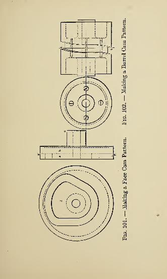
to
'M
c3ooo3
p«
104 PATTERNMAKING KINKS
then spread them properly for the other outline,
and use as before. At least two brads must now
be placed within the outline of d, long enough to
locate it on disk b. The part a is still in one
piece, and is next marked for replacing, and
unscrewed from b, and the internal face of the
groove in it is band-sawed and smoothed up.
Usually a large part of the edge of d can be
finished on the sandpaper disk wheel when one is
available.
The body of the cam is now assembled in its
former position, the screws and brads locating it,
and this time it is fastened permanently, the place
made by the saw blade being filled with a little
spline. This completes the pattern proper, all
except shellacking, etc.
A very cheap blank pattern, about j inch in
thickness, is next sawed out, the shape and size
of the metal templet, with finish added. This
makes the form to go in the cam-cutting machine
in the machine shop and is fastened to one spindle,
and the cam itself is attached to another, while
both turn in unison as the cutting progresses.
Fig. 102 shows a method of making the common
PATTERN FOR A STRAINER 105
barrel cam, having the groove cast in, which is
sometimes adopted on cheaper grades of work.
The pattern work consists of two separate pat-
terns, the castings made from them being fastened
together by screws on line a b. This allows the
groove or slot to be cast without a core, and saves
milling out the slot from the solid when a core is
undesirable.
Cams made in this manner can be used with
the cam surfaces just as cast, or they may be
finished, according to circumstances, and this
form admits also of taking up wear by facing off
a trifle on a b.
A PATTERN FOR A STRAINER
Having received an order to make a pattern
for a strainer, 24 x 12 x 12 inches, and put in it
as many J-inch holes as possible, the metal to be
J inch thick (Fig. 103) the most particular part
of the job was that it had to be made cheaply
and in a rush. Also the holes were to be cored
through, so as to avoid any extra chipping on
the casting. We made a box out of IJ-inch pine;
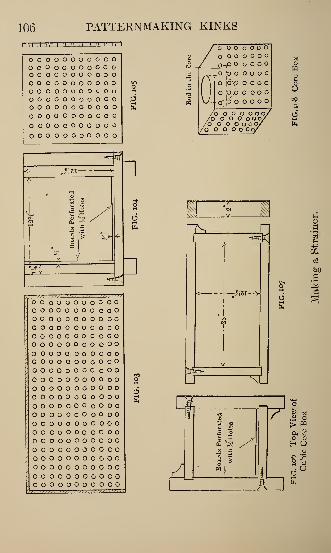
106 PATTERNMAKING KINKS
_J-!.L.l -n-rr ~xz
ooooooooooooooooooooooOOOOOOOOOOOOOOOOOOOOOOOOOOOOOOOOOooooooooooooooooooooooooooooooooooooooooooooooooooooooo
,-yrS-T-
§ £
««<1
' o o o o o o o o o o o
; o o o o o o o o o o
; o o o o o o o o o'. O O o o o o o o o- O o o o o o o O
; o o o o o o o O
/ o o o o o o o o Oo o o o o o o o o o
; o O o o o o o o o o• o o o o o o o o oo o o o o o o o o
I o o o o o o o o o o o
: o o o o o o o o o o o! o o o o o o o o o' o o o o o o o o o' o o o o o o o o oo o o o o o o o o o o
o o o o o o o o o o: o o o o o o o o o o oo o o o o o o o o O
; o o o o o o o o o o o: o o o o o o o o o
/o o O O o
o o o o
QpO O o OXo03
uOOo0.
.a'oo O O O
o, \6\o O O O
oi !o ,b o o o o
oljo'ooooo
to o o o o o o/O O O o o o/O O O O o o/O O O OO/
s
Li
ns_ n^<
A
1 w
9
u
m
of)
BM
J> P3
H 3
Z1 E
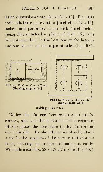
PATTERN FOR A STRAINER 107
inside dimensions were 12} x 12} x 12} (Fig. 104)
and made three pieces out of }-inch stock 12 x 12}
inches, and perforated them with ^-inch holes,
seeing that all holes had plenty of draft (Fig. 105)
We fastened them in the box, one at the bottom
and one at each of the adjacent sides (Fig. 106).
FIG, 1 09 Sectional View of Cores
Placed on Swept up Bed
v j juuu aacrqnnn a an
Cp
O)3
cp
OPn nnnnnni
FIG.IIO Top View of Cores after
being Placed in Mold
Making a Strainer.
Notice that the core box comes apart at the
corners, and also the bottom board is separate,
which enables the coremaker to dry the core on
the plain side. He should also see that he places
a rod in the top part of the core so as to form a
hook, enabling the molder to handle it easily.
We made a core box 28 x 12} x 2 inches (Fig. 107).
108 PATTERNMAKING KINKS
After four cores are made out of each box, all
the molder needs do is to strike up a bed in the
sand and place the four cubic cores together,
seeing that the plain faces come on the joints
and on the top of the mold. After placing cores
properly, place the cake cores around the cubic
cores; then ram green sand around the outside,
and the mold is completed with the exception of
striking a plain cope to place on top.
ENLARGING AN OLD FLY-WHEELPATTERN
The sketch, Fig. Ill, shows a fly-wheel whose
rim is to be enlarged § inch all around. Now,
there are two ways of doing this work. One is to
find the center of the wheel, rechuck it upon a
face-plate in the lathe; then, facing the outside
surface of the rim, glue thin segments all over it.
These may later be turned down to the required
thickness. To follow such a method involves too
much outlay of time and labor, to say nothing
about whether the work can be satisfactorily done
in this way. One thing is sure: it would be a
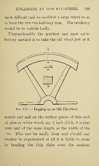
ENLARGING AN OLD FLY-WHEEL 109
most difficult task to re-chuck a large wheel so as
to have the rim run half-way true. The tendency
would be to wabble badly.
Unquestionably the quickest and most satis-
factory method is to take the old wheel just as it
Fig. 111. — Lagging up an Old Fly-wheel.
stands and nail on the surface pieces of thin slab
of pine or white wood, say-finch thick, 9 inches
wide and of the same length as the width of the
rim. This can be easily done and should any
trouble be experienced at all it is liable to come
in bending the thin slabs over the surface.
110 PATTERNMAKING KINKS
Sometimes these are apt to split, particularly if
the curve is a little sharp. Let the slabs be hol-
lowed out on the under side as at A; then they
can be easily nailed on the surface of the rim, as
shown in cross-section at B, without the least
fear of splitting. They bend with the utmost
ease. To hollow out the slabs pass them side-
ways over a circular saw in motion and but few
minutes will be required to do it. With this
hollowing-out process there is absolutely no need
of a gouge or round plane, the circular saw will
do the work quicker and better. Slabs thus
treated become quite pliable, and when firmly
nailed can be trimmed off even with the sides of
the rim. Then the whole may be sandpapered
and varnished, making on the whole quite a
respectable job.
RIG FOR BORING OUT LARGE COREBOXES
We had to have a large number of barrel cores
ranging from 17 to 22 inches in diameter and
about 6 feet long. It was very essential that the
BORING OUT LARGE CORE BOXES 111
cores should be just the proper diameter and
perfectly cylindrical.
We had been using wooden half core boxes
made in the usual way. These were constantly
getting out of shape from the severe handling by
the coremakers, swelling of the wood, etc. It
was finally decided to make a cast-iron core box
as shown by the sketch, Fig. 112; this was made
large enough to allow for lagging up inside with
wooden staves. The cast-iron box was planed
off true on the upper side. As there were con-
tinually different sizes of cores wanted ranging as
stated above, we concluded to get out a rig for
boring out the box. The rig when once fitted to
the box was easily taken off and put on again,
the straps bored out to form bearings for the bar
being held in place by cap-screws, and the bearings
being so fitted that they would bring the boring
bar exactly in the center of the box. The bar
consisted of a piece of cold-rolled shafting 1^|
inches diameter and about 8 feet long. On one
end of the bar was fastened a grooved collar to
which the feed lever was attached; both collar
and lever were taken from an old friction clutch
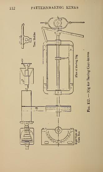
112 PATTERNMAKING KINKS
S
|o oo|
V_ I 'V,,
CO
&JD
tf obfl
,fi
CI0)
pqOO
o bCa^H
opqiH
o^4-1
ta
rt
BORING OUT LARGE CORE BOXES 113
countershaft found in the iron shed. On the
other end of the bar was mounted a pulley about
14 inches in diameter and 4 inches face. On the
bar, between the bearings, was placed the tool-
holder which was so constructed as to permit it
to be easily clamped at any point on the bar.
With this arrangement we could bore a length of
about 18 inches, then would draw the bar back,
move up the tool-holder and cut another 18
inches, and so on until the full length was fin-
ished. In order to drive the bar, we set the
core box and rigging on trestles in front of
the patternmaker's lathe, and drove it by a belt
from a roll mounted in the lathe and which
was about 8 inches in diameter and 2 feet long.
The belt moved along on the roll as the bar
was fed back and forth. In this way we could
get any speed desired from the cone pulley on
the lathe.
The rig worked very well, made a very accurate
core box and took only a fraction of the time
which would have been required to work it out
by hand. When a different size box was wanted
we simply took off the ends, removed the old
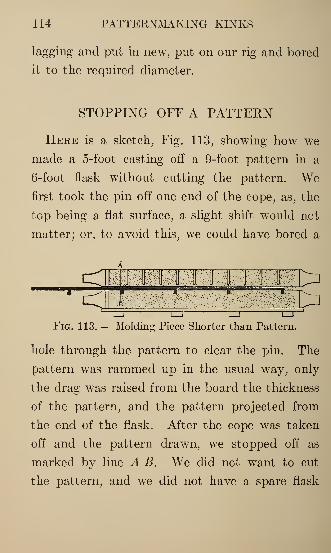
114 PATTERNMAKING KINKS
lagging and put in new, put on our rig and bored
it to the required diameter.
STOPPING OFF A PATTERN
Here is a sketch, Fig. 113, showing how we
made a 5-foot casting off a 9-foot pattern in a
6-foot flask without cutting the pattern. Wefirst took the pin off one end of the cope, as, the
top being a flat surface, a slight shift would not
matter; or, to avoid this, we could have bored a
<cr
MT
TTTTl^ i
Fig. 113. — Molding Piece Shorter than Pattern.
hole through the pattern to clear the pin. The
pattern was rammed up in the usual way, only
the drag was raised from the board the thickness
of the pattern, and the pattern projected from
the end of the flask. After the cope was taken
off and the pattern drawn, we stopped off as
marked by line A B. We did not want to cut
the pattern, and we did not have a spare flask
SAVING PATTERN WORK 115
long enough to take all the pattern, so this was
a case of necessity.
STOPPING OFF AND SAVING PATTERNWORK
The term "stopping-off/ 7
as used in the pat-
tern shop, means that some part or parts appear-
ing on the pattern itself are not to be reproduced
in the casting. An understanding of this principle
of stopping off will often save a number of dollars
in the pattern shop, when a special job is required
similar to some pattern already made, and yet
unlike it in some particular. Quite often the
expense of a new pattern is saved by a little
study along this line. It is our purpose to illus-
trate a few cases, beginning with the simplest
and leading up to one or two a little more
difficult.
The part of a pattern to be stopped off may
be either some supplementary portion, used for
strengthening or other purposes, or it may be
some part of the pattern itself; but, in all cases,
the term implies a filling up of some part of the
116 PATTERNMAKING KINKS
mold as made by the pattern, which is the real
"stopping off."
The very simplest examples possible are those
where some part of the mold is filled up level, as
indicated by patterns in Figs. 114 and 115, The
first figure illustrates a thin pattern requiring
battens to hold it in shape. The second is thin
work also, but it has a stop-off block, to accom-
modate good-sized screws for holding the draw
plate. It is perfectly plain that any hub or boss
on a pattern can be left off the casting in this
manner.
Different pattern shops have different signs to
indicate to the molder what is to be stopped off.
Some paint the part a different color, some cross
hatch the part with parallel lines in another color
with the shellac brush, others simply paint the
words "Stop Off" on the part, while still others
will cross line the part with chalk. Chalk is very
commonly used where the part to be stopped off
is some part of a regular pattern and only used
once in this special manner.
Fig. 116 is an example of a pattern to be
parted on the line A B and having a thin piece
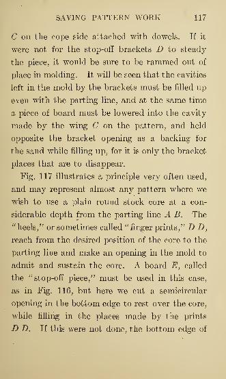
SAVING PATTERN WORK 117
C on the cope side attached with dowels. If it
were not for the stop-off brackets D to steady
the piece;
it would be sure to be rammed out of
place in molding. It will be seen that the cavities
left in the mold by the brackets must be filled up
even with the parting line, and at the same time
a piece of board must be lowered into the cavity
made by the wing C on the pattern, and held
opposite the bracket opening as a backing for
the sand while filling up, for it is only the bracket
places that are to disappear.
Fig. 117 illustrates a principle very often used,
and may represent almost any pattern where we
wish to use a plain round stock core at a con-
siderable depth from the parting line A B. The
"heels/ 7
or sometimes called "finger prints," D D,
reach from the desired position of the core to the
parting line and make an opening in the mold to
admit and sustain the core. A board E, called
the "stop-off piece/' must be used in this case,
as in Fig. 116, but here we cut a semicircular
opening in the bottom edge to rest over the core,
while filling in the places made by the prints
D D. If this were not done, the bottom edge of
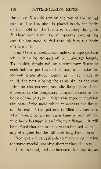
118 PATTERNMAKING KINKS
the piece E would rest on the top of the round
core, and as the piece is placed inside the body
of the mold on the line x y, covering the space
D, there would still be an opening around the
core for the sand to fall through into the body
of the mold.
Fig. 118 is a familiar example of a pipe pattern
which is to be stopped off to a shorter length.
To do this, simply nail on a temporary flange to
each half, as per the dotted lines, and make the
stop-off piece shown below at A, to place in
mold, the part c being the same size as the core
print on the pattern, and the flange part d the
diameter of the temporary flange fastened to the
body of the pattern. With this piece in position
the part of the mold which represents the flange
on the end of the pattern is filled in, and also
what would otherwise have been a part of the
pipe body between it and the new flange. It will
be noticed that the same core can be used without
any changing for the different lengths of pipe.
Frequently it is desirable to make a leg casting
for some special machine shorter than the regular
pattern on hand, and at the same time not injure
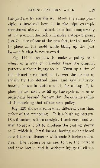
SAVING PATTERN WORK 119
the pattern by cutting it. Much the same prin-
ciple is involved here as in the pipe example
mentioned above. Attach new feet temporarily
at the position desired, and make a stop-off piece,
just the size of one of the new feet, for the molder
to place in the mold while filling up the part
beyond it that is not wanted.
Fig. 119 shows how to make a pulley or a
wheel of a smaller diameter than the original
pattern without injury to it. Turn up a rim of
the diameter required, fit it over the spokes as
shown by the dotted lines, and saw a curved
board, shown in section at A, for a stop-off, to
place in the mold to fill up the spokes, or arms
projecting beyond the new rim, the outside radius
of A matching that of the new pulley.
Fig. 120 shows a somewhat different case than
either of the preceding. It is a bushing pattern,
18 x 6 inches, with a straight 4-inch core, and we
wish to stop it off to produce the casting shown
at C, which is 12 x 6 inches, having a chambered
core 4 inches diameter with ends 3 inches diam-
eter. The requirements are, to use the pattern
and core box A and B, without injury to either.
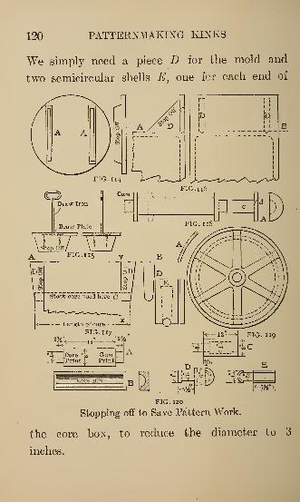
120 PATTERNMAKING KINKS
We simply need a piece D for the mold and
two semicircular shells E, one for each end of
r~l
i"1
ja 'd
i ! II
FIG.nG
FIG. 120
Stopping off to Save Pattern Work.
^
the core box, to reduce the diameter to 3
inches.
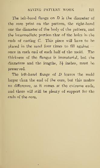
SAVING PATTERN WORK 121
The left-hand flange on D is the diameter of
the core print on the pattern, the right-hand
one the diameter of the body of the pattern, and
the intermediate portion that of the holes in the
ends of casting C. This piece will have to be
placed in the sand four times to fill against —£>nce in each end of each half of the mold. The
thickness of the flanges is immaterial, but the
diameters and the lengths, 5J inches, must be
preserved.
The left-hand flange of D leaves the mold
larger than the end of the core, but this makes
no difference, as it comes at the extreme ends,
and there will still be plenty of support for the
ends of the core.

INDEX
PAGE
Adjustable round-soled planes 45
Angular tool-post for lathe , . 15
Band-saw, friction drive for 54
how to fold 57
putting band on a 56
Barrel cam patterns 104
Block for turning tool 87
Boring large core boxes 110
Box for brads 82
for shavings 53
Brads, box for 82
Buzz planer thickness gage 33
Calipers for large work 31
Cam patterns 101
Centers for patternmakers' lathes 1
Chest for tools 19, 21
Circular work 91
Combination tool 40
Cone pulley patterns 96
Core box kinks 81
boxes, boring 110
boxes, planing taper 79
making its own 94
123
124 INDEX
PAGE
Corner rounding tool 18
Cutter for plugs 51
Dowel rods 29
Enlarging fly-wheel pattern 108
Face cam patterns . 101
plate for lathes 30
wrench 58
Filleting wooden patterns 71
Fillets, lead 73
leather 73
wooden 74
Fly-wheel pattern, enlarging 108
quickly made 78
Folding a band-saw . 57
Friction drive for band-saw 54
Gage for buzz planer 33
hight 36
scratch 48
surface 48
Gages for patternmakers 38
Gouge sharpener 31
Grain in lumber 61
Hight gage 36
Holder for loose pieces 85
Judgment in parting patterns 66
INDEX 125
PAGELathe centers, patternmakers' , 1
for patternmakers 5
tool post 15
tools 9
Lead fillet 73
Leather fillet 73
Letter mold 42
Loose piece holder for patterns 85
Lumber, grain in 61
required, quick method 88
Making its own core 94
Mold for pattern letters 42
Parting patterns, judgment in 66
Patternmakers' lathe centers 1
Planes for patternmakers 44
Planing taper core boxes 79
Plug cutter 51
Pulley patterns 76
cone 96
Pump repair pattern 41
Putting band on band-saw wheel , . . 56
Quarter sawing of lumber 62
Quick calculation for stock 88
Quickly made fly-wheel pattern 78
Repairs to patterns, waxing , 77
Round-soled planes 44, 45
Saving pattern work 115
126 INDEX
PAGE
Scratch gage . 22, 48
Sharpener for gouges 31
Shaving box 53
Small planes 47, 44
Square feet of lumber, quick method 88
Stopping off patterns 114, 115
Strainer pattern 105
Surface gage 48
T square 22
Taper core boxes, planing 79
Thickness gage for buzz planer 33
Tool-chest 19
for rounding corners 18
post for lathe 15
Tools for apprentices 23
for patternmakers' lathes 9
for turning 3
Trammel bar 33
Turning tool block 87
tools 3-
Waxing patterns to repair 77
Web made of strips 84
Wooden fillets 73
patterns, filleting 71
X-ray pattern work ._.,.,,., 76
HAVE YOU THESE?Practical Planer Kinks. By Carroll Ashley. 80
pages, 5x8, 34 illustrations. $1.00 postpaid.
Dimensions and Weights of Pipe and Fittings.
11x8. $.50 postpaid.
The Electrical Catechism. Compiled by the Power
editors from Power. 5fx7j, 246 illustrations. $2.00
postpaid.
Manufacture and Properties of Iron and Steel. ByHarry Huse Campbell. Entirely revised in 1907,
641 pages, 6x9, cloth. $5.00 postpaid.
Precision Grinding. By H. Darbyshire. 6x9, cloth,
fully illustrated. $2.00 postpaid.
Steam Turbines. By Lester G. French. 340 pages,
6x9, cloth, fully illustrated. $3.00 postpaid.
Engine Room Chemistry. By Prof. Augustus H.Gill of the Massachusetts Institute of Technology.
4jx6j, fully illustrated. $1.00 postpaid.
Eminent Engineers. By Dwight Goddard. 280 pages,
5x8. $1.50 postpaid.
Combustion and Smokeless Furnaces. By Joseph
W. Hays. 112 pages, 6x9, illustrated. $1.50 post-
paid.
The Compound Engine. By F. R. Low, editor of
Power. 48 pages, 6 x 9, 37 illustrations. $.50 post-
paid.
Condensers. By F. R. Low, editor of Power. 80pages, 6x9, 23 illustrations. $.50 postpaid.
The Steam Engine Indicator. By F. R. Low, editor
of Power. 208 pages, 6x9, illustrated. $1.50 post-
paid.
Questions and Answers from the American Machinist.Compiled by Frank Richards. 420 pages, 5x7. $1.50
postpaid.
Chordal's Letters. By James W. See. 396 pages,
5x8, 32 illustrations. $2.00 postpaid.
The Design and Construction cf Cams. By C. F.
Smith, F. A. Halsey, and others. 70 pages, 9x12,fully illustrated. $3.00 postpaid.
Things that Are Usually Wrong. By Prof. John E.
Sweet. 52 pages, 5x8, 50 illustrations. $.50 post-
paid.
Grinding and Lapping. Tools, Processes and Fixtures.
By Joseph V. Woodworth. Author of "Dies,"
"Punches, Dies and Tools," "American Tool-Making
and Interchangeable Parts," etc., etc. 200 pages, 6x9,fully illustrated. $2.00 postpaid.
HILL PUBLISHING CO.
505 Pearl Street, - - New York
6 Bouverie Street, - - London, E. C.
The Engineering and Mining Journal, Power,
American Machinist