Embed Size (px)
DESCRIPTION
ADXL345 Tutorial
Citation preview

10/23/13 Live Fast - Code Young: ADXL345 accelerometer breakout board + Arduino and Processing
codeyoung.blogspot.com/2009/11/adxl345-accelerometer-breakout-board.html 1/41
A software engineer's blog
Live Fast - Code Young
Monday, November 30, 2009
ADXL345 accelerometer breakout board + Arduino and Processing
Some time ago I've purchased an ADXL345 accelerometer breakout board from SparkFun.com. After
some searching and datasheeting (that's an awful term, I know :D), I've finally came up with code,
which will allow me to talk to the accelerometer using my Arduino and even pass the data on, to
Processing (it's a fun language, covered in my previous post)
In this post I will cover the setup for the communication procedure between the ADXL345 and the
Arduino and then, between the Arduino and Processing (ie your PC). All the sources are at the bottom
of the post, as usual. (Code is now updated for Arduino 1.0.4)
To tell you the truth, I don't know which you should do first, code the Arduino or hook up the ADXL
(probably code first), but my fingers were itchy, so I hooked up the ADXL to the Arduino first:
► 2013 (1)
► 2012 (1)
► 2011 (1)
▼ 2009 (8)
► December (1)
▼ November (2)
ADXL345accelerometerbreakout board+ Arduino and...
Programmer andArtist?(Processing andpixlr.com d...
► July (1)
► May (1)
► April (1)
► February (1)
► January (1)
Blog Archive
accelerometer (2)
acelerometro (2)
adxl345 (2)
animation (1)
animator (1)
arduino (2)
art (1)
browser (1)
c# (1)
chat (1)
cli (2)
client (2)
code (2)
command line (2)
console (1)
copying (1)
cs homework (1)
debug (1)
default (1)
example (2)
Labels
Share 7 More Next Blog» Create Blog Sign In
10/23/13 Live Fast - Code Young: ADXL345 accelerometer breakout board + Arduino and Processing
codeyoung.blogspot.com/2009/11/adxl345-accelerometer-breakout-board.html 2/41
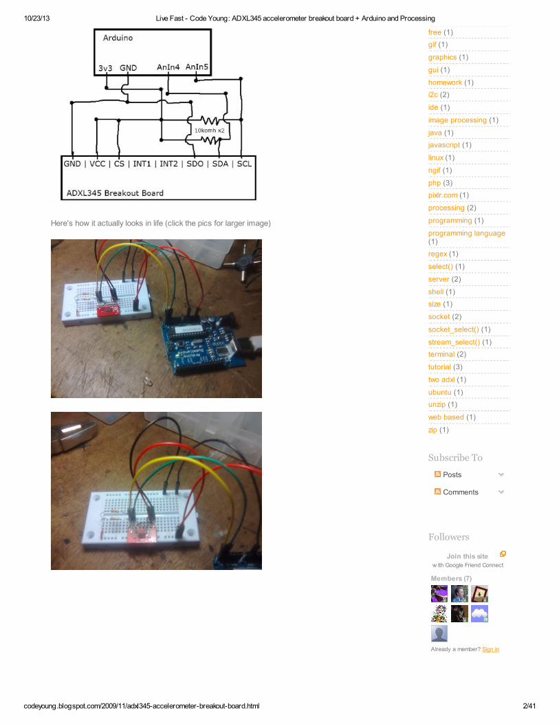
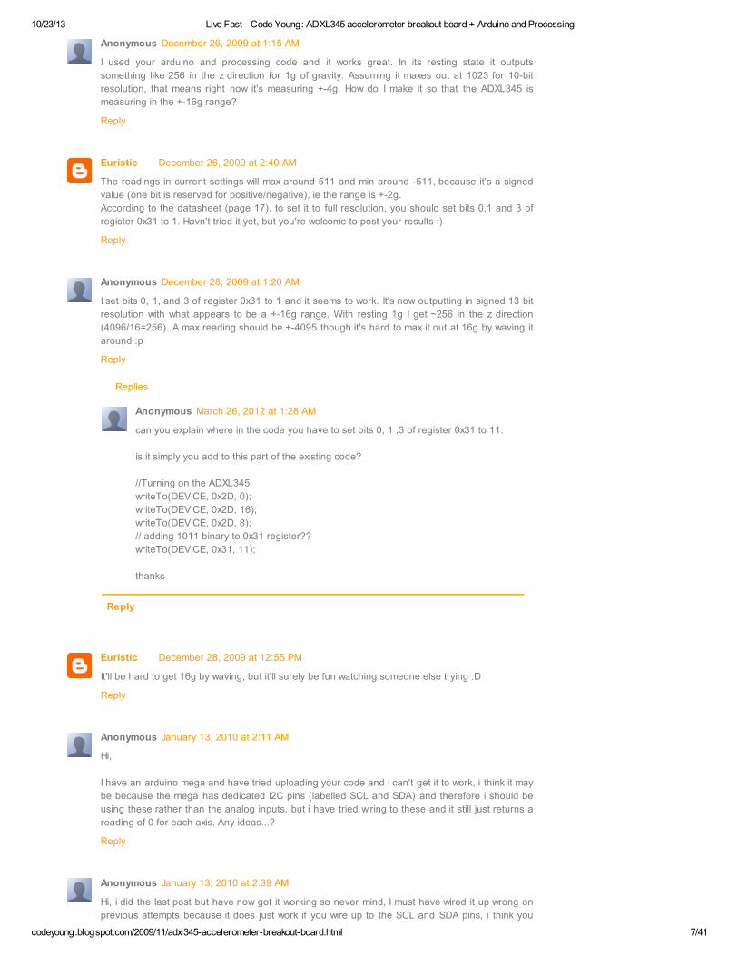
Here's how it actually looks in life (click the pics for larger image)
free (1)
gif (1)
graphics (1)
gui (1)
homework (1)
i2c (2)
ide (1)
image processing (1)
java (1)
javascript (1)
linux (1)
ngif (1)
php (3)
pixlr.com (1)
processing (2)
programming (1)
programming language(1)
regex (1)
select() (1)
server (2)
shell (1)
size (1)
socket (2)
socket_select() (1)
stream_select() (1)
terminal (2)
tutorial (3)
two adxl (1)
ubuntu (1)
unzip (1)
web based (1)
zip (1)
Subscribe To
Posts
Comments
Join this sitew ith Google Friend Connect
Members (7)
Already a member? Sign in
Followers

10/23/13 Live Fast - Code Young: ADXL345 accelerometer breakout board + Arduino and Processing
codeyoung.blogspot.com/2009/11/adxl345-accelerometer-breakout-board.html 3/41
Now, after we have everything plugged in nicely, we may start writing the code for getting the
acceleration values from the sensor. You might want to have the ADXL345 Datasheet handy while you
code.
There are two ways to talk to the sensor, SPI and I2C protocols. I've chose the I2C (the schematics
above are for I2C communication) because it is easier to wire for, and easier to code - the downside,
they say, is that I2C is slower.
The Arduino Wire library provides a sort-of-easy way to interact with components that implement the
I2C communication protocol. I wish I could say it's usage is straightforward, but it is not quite so. There
are few catches! Though, if you're aware of them, the library should be easy to use.
Open page 10 in the datasheet, this page explains how to talk to the device using I2C protocol. When
using I2C protocol there are two ways (yes, again two ways) to wire the ADXL345, each way gives it a
different device address (so that may prevent address collision). You can see, that the wiring I chose,
defines the device address as 0x53, the datasheet also says that this translates to 0xA6 address for
write and 0xA7 address for read (because the base device address is 7-bit + 1 read/write bit). Ignore
the read and write addresses as the Wire library takes care of this for us (catch).
Now, at the bottom of page 10 in datasheet, you see a diagram of how reads and writes should be
performed. We'll start with the writes because:
1. It's what we do first in the code
2. Surprisingly, it's easier to do
The diagram shows that in order to perform a write to a register on a device, we need to go through the
following steps:
1. Initiate transmission to device (using write address*)
2. Write the address of the register we want to write
3. Write the data we want to write to the register
4. Finish transmission
* We only use the base address of the device (0x53) because the read/write bit is handled by the Wire
library.
** You will also note that there are 'ack' signals coming from the device, those are too, handled by the
library
Looks pretty logical, and here's a function that will write a value to a certain register on a specified
device (you'll need to add #include <Wire.h> to the top of your program to use the Wire library):
void writeTo(int device, byte address, byte val) {
Wire.beginTransmission(device); //start transmission to device
Wire.write(address); // send register address
Wire.write(val); // send value to write

10/23/13 Live Fast - Code Young: ADXL345 accelerometer breakout board + Arduino and Processing
codeyoung.blogspot.com/2009/11/adxl345-accelerometer-breakout-board.html 4/41
Wire.endTransmission(); //end transmission
}
So, let's say we want to write the value 8 to register 0x2D on device 0x53 (true story :D), we'll use this
function like that:
writeTo(0x53, 0x2D, 8);
Ok, that was easy. The reading function is a bit longer, but uses similar concepts, so it's not going to be
hard to follow. This time we want to perform a multiple-byte reading (as opposed to single byte writing
we did in the writeTo() function). We need to read 6 bytes of data from the sensor (2 bytes for each
axis), because, as the datasheet suggests, we don't want one axis value to change while we're reading
another axis' values.
Lets look at that communication diagram on page 10 of the datasheet again. The steps we are to follow,
in order to perform a multi-byte reading, are:
1. Initiate transmission to device (using write address*)
2. Write the address of the register we want to start** reading from
3. Initiate transmission to device, again! (using read address*)
4. Read bytes one after another
5. Finish transmission
* Again, we only use the base address of the device (0x53) because the read/write bit is handled by the
Wire library.
** When we're doing multiple bytes read (or write) we provide the start address - for example 0x15 -
and the number of bytes we want to read - for example 4. That way we'll read values of registers 0x15,
0x16, 0x17, 0x18
So, let's see the read function:
void readFrom(int device, byte address, int num, byte buff[]) {
Wire.beginTransmission(device); //start transmission to device
Wire.write(address); //sends address to read from
Wire.endTransmission(); //end transmission
Wire.beginTransmission(device); //start transmission to device (initiate
again)
Wire.requestFrom(device, num); // request 6 bytes from device
int i = 0;
while(Wire.available()) //device may send less than requested (abnorm
al)
{
buff[i] = Wire.read(); // receive a byte
i++;
}
Wire.endTransmission(); //end transmission
}
The new elements in this function are
Wire.requestFrom(device, num) - requests num number of bytes from device. The reading
will start from the register passed in the Wire.write() call.
Wire.available() - returns true if there's something to read from the device
Wire.read() - reads one byte from the device
Essentially, this function performs the reading steps listed above. One thing to note, the result is saved
in the buff array, and not returned by the function. So you must pass an array to the function and it has

10/23/13 Live Fast - Code Young: ADXL345 accelerometer breakout board + Arduino and Processing
codeyoung.blogspot.com/2009/11/adxl345-accelerometer-breakout-board.html 5/41
to be long enough to hold the data.
Whew! Ok, we have the read and write functions set. We're ready to write a program that will talk to the
sensor (finally).
#include <Wire.h>
#define DEVICE (0x53) //ADXL345 device address
#define TO_READ (6) //num of bytes we are going to read each time (
two bytes for each axis)
byte buff[TO_READ] ; //6 bytes buffer for saving data read from the dev
ice
char str[512]; //string buffer to transform data befo
re sending it to the serial port
void setup()
{
Wire.begin(); // join i2c bus (address optional for master)
Serial.begin(9600); // start serial for output
//Turning on the ADXL345
writeTo(DEVICE, 0x2D, 0);
writeTo(DEVICE, 0x2D, 16);
writeTo(DEVICE, 0x2D, 8);
}
Most of the code is pretty self-explanatory, so I'll explain only the code after the //Turning on the
ADXL345 comment.
As you can see we are writing three different values to register 0x2D. 0x2D is the Power Control
register of the ADXL345 (see datasheet). We first reset the power control register, then put the sensor
in standby mode, and last we are putting it in to measure mode. We're doing the writes one after
another because that's what the datasheet recommends. We could simply do the last write also. If you
don't turn on the fourth bit on (writeTo(DEVICE, 0x2D, 8)) the sensor will be in sleep mode, and will give
zero readings!!
And now, finally, the reading loop:
void loop()
{
int regAddress = 0x32; //first axis-acceleration-data register on the
ADXL345
int x, y, z;
readFrom(DEVICE, regAddress, TO_READ, buff); //read the acceleration dat
a from the ADXL345
//each axis reading comes in 10 bit resolution, ie 2 bytes. Least Sign
ificat Byte first!!
//thus we are converting both bytes in to one int
x = (((int)buff[1]) << 8) | buff[0];
y = (((int)buff[3])<< 8) | buff[2];
z = (((int)buff[5]) << 8) | buff[4];
//we send the x y z values as a string to the serial port
sprintf(str, "%d %d %d", x, y, z);

10/23/13 Live Fast - Code Young: ADXL345 accelerometer breakout board + Arduino and Processing
codeyoung.blogspot.com/2009/11/adxl345-accelerometer-breakout-board.html 6/41
Posted by Euristic at 18:03
Labels: accelerometer, acelerometro, adxl345, arduino, code, example, i2c, processing, tutorial
Serial.print(str);
Serial.write(10);
//It appears that delay is needed in order not to clog the port
delay(15);
}
Let's start from the beginning. The regAddress variable represents the register we want to start reading
from (registers 0x32 - 0x37 are acceleration data registers, page 18 in the datasheet). We're defining
the ints (x,y,z) which we'll use later, to send the data through serial port to Processing.
Next we're performing a readFrom function call, we pass our device's address, the register address to
start reading from , the number of bytes to read and the buffer in which to save the data.
Now comes the tricky part - convert the data received from 2 bytes in to one int. Each axis' pair of bytes
are manipulated, in order to create an int from two bytes using C bitwise operators (see here and here
for more info on bitwise operators in C).
Afterward we're using the sprintf() function to turn the integers we have in to one string. And then we
send that string to the serial port, terminating it with end-of-line character. The delay in the end is not
strictly necessary, but it gave me better performance that way.
That's it! Below is a link to the sources - it also contains a matching Processing application to read the
data and manipulate a model on the screen accordingly.
The next step is writing an actual 3D game for this thing, I'll probably do it using Microsoft's XNA studio,
which appears to be pretty awesome. Stay tuned. Questions and comments are of course welcomed.
Source code files
Old sources (for before 1.0.4)
+7 Recommend this on Google
215 comments:
Anonymous December 22, 2009 at 10:50 PM
hi,
just tested your setup, worked at first try!
thx a lot
Reply
gamemail December 23, 2009 at 5:11 AM
hi, may i ask some questions?
i'll follow these step to make my arduion with adxl 345.
Sometimes it always return 0.
Could you tell me why must it be this way?
Reply
Euristic December 23, 2009 at 11:41 AM
A reason I can think of, is that you don't take your ADXL out of sleep mode (it's in sleep by
default). In the code pieces I provide above look at the one with the "void setup()" function. The
writeTo's after the "//Turning on the ADXL" actually deal with that. Let me know if you can't work it
out.
Reply
10/23/13 Live Fast - Code Young: ADXL345 accelerometer breakout board + Arduino and Processing
codeyoung.blogspot.com/2009/11/adxl345-accelerometer-breakout-board.html 7/41
Replies
Reply
Anonymous December 26, 2009 at 1:15 AM
I used your arduino and processing code and it works great. In its resting state it outputs
something like 256 in the z direction for 1g of gravity. Assuming it maxes out at 1023 for 10-bit
resolution, that means right now it's measuring +-4g. How do I make it so that the ADXL345 is
measuring in the +-16g range?
Reply
Euristic December 26, 2009 at 2:40 AM
The readings in current settings will max around 511 and min around -511, because it's a signed
value (one bit is reserved for positive/negative), ie the range is +-2g.
According to the datasheet (page 17), to set it to full resolution, you should set bits 0,1 and 3 of
register 0x31 to 1. Havn't tried it yet, but you're welcome to post your results :)
Reply
Anonymous December 28, 2009 at 1:20 AM
I set bits 0, 1, and 3 of register 0x31 to 1 and it seems to work. It's now outputting in signed 13 bit
resolution with what appears to be a +-16g range. With resting 1g I get ~256 in the z direction
(4096/16=256). A max reading should be +-4095 though it's hard to max it out at 16g by waving it
around :p
Reply
Anonymous March 26, 2012 at 1:28 AM
can you explain where in the code you have to set bits 0, 1 ,3 of register 0x31 to 11.
is it simply you add to this part of the existing code?
//Turning on the ADXL345
writeTo(DEVICE, 0x2D, 0);
writeTo(DEVICE, 0x2D, 16);
writeTo(DEVICE, 0x2D, 8);
// adding 1011 binary to 0x31 register??
writeTo(DEVICE, 0x31, 11);
thanks
Euristic December 28, 2009 at 12:55 PM
It'll be hard to get 16g by waving, but it'll surely be fun watching someone else trying :D
Reply
Anonymous January 13, 2010 at 2:11 AM
Hi,
I have an arduino mega and have tried uploading your code and I can't get it to work, i think it may
be because the mega has dedicated I2C pins (labelled SCL and SDA) and therefore i should be
using these rather than the analog inputs, but i have tried wiring to these and it still just returns a
reading of 0 for each axis. Any ideas...?
Reply
Anonymous January 13, 2010 at 2:39 AM
Hi, i did the last post but have now got it working so never mind, I must have wired it up wrong on
previous attempts because it does just work if you wire up to the SCL and SDA pins, i think you

10/23/13 Live Fast - Code Young: ADXL345 accelerometer breakout board + Arduino and Processing
codeyoung.blogspot.com/2009/11/adxl345-accelerometer-breakout-board.html 8/41
Replies
Reply
have to wire it up before uploading the code for it to work. Thanks for the code!
Reply
Anonymous January 17, 2010 at 8:48 AM
What a time-saver. Your posting of this code and explanations helped me come up to speed on
this device without having to study the data sheet id detail. I've used I2C before and I have used
the Arduino, but never the two together. Thanks so much for your time and generosity in posting
this!!
Reply
Euristic January 21, 2010 at 1:00 AM
Very welcome :) Glad it's helpful
Reply
Anonymous January 23, 2010 at 8:56 AM
Thanks for the time saver.
If you want to decrease the code size by 25%, you can try this new loop(). It worked for me. It
works because the CPU is little endian, just like an x86 CPU.
#define DATAX0 0x32 //X-Axis Data 0
void loop()
{
int axis[3] ; //6 bytes buffer for saving data read from the device
//each axis reading comes in 10 bit resolution, ie 2 bytes. Least Significat Byte first!!
//thus we are converting both bytes in to one int
readFrom(DEVICE, DATAX0, sizeof(axis), (byte*)axis); //read the acceleration data from the
ADXL345
//we send the x y z values as a string to the serial port
Serial.print(axis[0], DEC);
Serial.print('\t');
Serial.print(axis[1], DEC);
Serial.print('\t');
Serial.println(axis[2], DEC);
}
Reply
Anonymous May 20, 2013 at 6:48 PM
Hey thanks alot for posting this as I have been trying to get the the serial monitor to
display x,y, and z accelerations seperately. I dont fully understand how to place your
code into the existing code. If I could see your full code which displays the x,y, and z
accelerations seperately, I would be tremendously greatful.
my email is [email protected]
Euristic May 21, 2013 at 10:20 AM
What do you mean when you say "separately"? In the original code they're separated by
spaces, and here they are separated by tabs. If you want to use this output instead of
the original you put this:
sprintf(str, "%d\t%d\t%d", x, y, z);
instead of this:
sprintf(str, "%d %d %d", x, y, z);

10/23/13 Live Fast - Code Young: ADXL345 accelerometer breakout board + Arduino and Processing
codeyoung.blogspot.com/2009/11/adxl345-accelerometer-breakout-board.html 9/41
Euristic January 23, 2010 at 10:50 AM
Thanx for the tip! Very elegant. To be frank though, in a recent project I did, I passed the bytes as-
is to the PC, and converted them there. On the other hand this same conversion technique can be
used on the PC as well :)
Reply
Alex Pedenko March 10, 2010 at 7:39 AM
is it possible to run two of these guys over spi on a single arduino?
Reply
Anonymous March 14, 2010 at 10:45 AM
Hi,
e
Thanks for this tutorial.
I tried your code and schematic, but no success :
http://www.arduino.cc/cgi-bin/yabb2/YaBB.pl?num=1268490789
I always get 0 0 0 0.
Do you have an idea?
What do you mean looking at the wake up lines? I tried delays but...
Thanks !
tep
Reply
Euristic March 14, 2010 at 12:45 PM
Have you tried connecting everything without the unit in the middle? Only the ADXL and the
Arduino?
I also answered you in the forum on the link you've post, lets continue the discussion there
Reply
Anonymous March 19, 2010 at 2:58 AM
@Alex: should be possible without a spi if you get different addresses for the two adxls, no?
Reply
Don March 20, 2010 at 7:47 PM
when using your sketch I'm gettingthe following error when trying to compile the code.
In function 'void loop()':
error: 'sprintf' was not declared in this scop
Any ideas as how to fix this issue?
Reply
Euristic March 20, 2010 at 10:35 PM
I don't know why are you having problems with sprintf, but instead you could simply use
Serial.print(x, DEC), and same for y and z (with spaces between them).
Reply
Anonymous March 21, 2010 at 8:37 AM
Wonderful! Thanks so much for the code.

10/23/13 Live Fast - Code Young: ADXL345 accelerometer breakout board + Arduino and Processing
codeyoung.blogspot.com/2009/11/adxl345-accelerometer-breakout-board.html 10/41
And if you've been trying different code, Googling, and looking over your schematic for the past
two hours... check to make sure that you're plugged into ANALOG 4 and 5, not digital pins 4 and 5
on the Arduino. *palm->face*
Reply
Anonymous March 24, 2010 at 10:22 AM
Hi Euristic.
I a new user. Now I using the Arduino Mega(ATmega1280) and Sensor ADXL345.
I try to wire along diagram that you show above but change AnIn4 to SCL Pin on board, AnIn5 ->
SDA Pin on board. And upload coding to Arduino. and Run coding on Processing. It doesn't work.
Can you suggest me. How should I do next setp. Thank for you help.
Reply
Euristic March 24, 2010 at 11:05 AM
Hi Anonymous.
It's vice versa my friend. AnIn4 is SDA (data) and AnIn5 is SCL (clock). According to the Arduino
Wire library page, on the Mega SDA is digital pin 20 and SCL is 21.
Hope that helps :)
Reply
Anonymous March 24, 2010 at 2:38 PM
Hi Euristic, I'm Methin who just post last message to you. Thank for your reply.
Yes, I wire SCL(ADXL345) to SCL(Arduino Mega), and wire SDA(ADXL345) to SDA(Arduino
Meag). and I correct the COM Port in Processing code already. But It doesn't work.
Do I need to modify code anymore?
Thank you for your help. :)
Ping
Reply
Euristic March 25, 2010 at 8:23 PM
Could you please email me about it, or make a thread on the Arduino forums so we can continue
this discussion there?
Reply
snoozzdoc March 26, 2010 at 4:05 AM
Hi, I just took your Processing code and modified it to do exactly the same thing with a Seeduino
Mega and an MMA7260QT 3-Axis Accelerometer from Pololu. This accelerometer puts out an
analogue voltave in the range 0 to 3.3 volts so I use the ADC on the Seeeduino Mega (equiv to
the Arduino Mega) and convert to 3-axis "G" force measurements before passing it to the
Processing code. It works just like yours.
Reply
Anonymous April 20, 2010 at 4:30 PM
You are a hero! Thank you kindly.
Reply
Mark Archer April 21, 2010 at 3:20 AM
Just what I needed. Thanks for breaking it down.
Reply

10/23/13 Live Fast - Code Young: ADXL345 accelerometer breakout board + Arduino and Processing
codeyoung.blogspot.com/2009/11/adxl345-accelerometer-breakout-board.html 11/41
Eduardo May 2, 2010 at 3:55 AM
Hi!
I m new to accelerometers so this is a really great start! I m trying to do the same, but using
adxl335. However I ve a doubt migrating the processing code! In this line:
r[0] = (float)(Integer.parseInt(s.substring(0, i = s.indexOf(" "))) +OFFSET_X)*HALF_PI/256;
the value 256 comes from your accelerometer datasheet, isn´t it?
Reading your code I also understood that you´re not using z axis data...Am I write? Why? Sorry for
this newbie questions :)
thanks!
Reply
Euristic May 3, 2010 at 11:25 PM
@Eduardo
Hi! the 256 number comes from me knowing that 1g will be measured by the adxl345 as 256. So i'll
always get a number between 0-0.5PI on both axes.
I'm not using the Z axis because I don't need it for that specific application (although I might've
needed it if wanted to be able to turn the model upside down). Hope, this helped!
Reply
Eduardo May 6, 2010 at 1:09 PM
Ok ! thanks a lot for the answer and for introducing me to the accelerometers! btw, It would be
great if you could make an "hello world" example to the accelerometer using the 3 axis :)
Best regards
Eduardo
Reply
Anonymous May 26, 2010 at 11:46 AM
Hello!
I am new to the area of the microcontroller, I will go into this field, I use adxl345 and AT90CAN128
(no Ardiuno), and I want to know what is wire.h and where can I download it?
Many thanks for any help
Simo
Reply
Euristic May 27, 2010 at 8:35 AM
Wire.h is a C++ header file, for the Wire.cpp file - which is the Arduino Wire library. It comes with
the Arduino IDE. You'll need both files to use the library, and I'm pretty sure you'll need an Arduino
also
Reply
Anonymous May 27, 2010 at 3:25 PM
but there is a possibility my microcontroller (AT90CAN128) and your code to get up and running,
without having to get an Arduino need?
thank you for your attention Euristic
Simo
Reply
Euristic June 12, 2010 at 8:15 PM
@Simo
I'm not sure, because it was written for the Arduino. Don't know if it's possible to just port it to
another platform...

10/23/13 Live Fast - Code Young: ADXL345 accelerometer breakout board + Arduino and Processing
codeyoung.blogspot.com/2009/11/adxl345-accelerometer-breakout-board.html 12/41
Reply
backTo June 25, 2010 at 7:05 AM
HI, may i ask some questions?
What is mean 8bit data in buffer?
example)
buffer[0] = 0x00 0xfc 0x00 0x01 0x03 0xff 0x00 0xec
Reply
Euristic June 26, 2010 at 2:43 PM
@backTo:
I'm not sure what exactly are you asking, but your example (buffer[0] = 0x00 0xfc 0x00 0x01 0x03
0xff 0x00 0xec) is putting 8 _bytes_ data in to one byte of the array. Each byte is 8 bit.
Reply
Anonymous July 20, 2010 at 2:00 PM
HI ~
Thanks to reply my question.
but I'm sorry that I have one more question.
I don't know why buff[1] is shifted 8bits...
there..
x = (((int)buff[1]) << 8) | buff[0];
Reply
Euristic July 21, 2010 at 6:06 PM
It's written in the code comments. Each axis info comes as 2 bytes, that's why we Shift and Or, to
merge two bytes in to one int.
Reply
austrisv July 29, 2010 at 9:06 PM
working like a charm. thanks a lot for making my first 3d accelerometer experience so easy! :)
Reply
Fabio Varesano August 8, 2010 at 8:32 PM
If you send the values of accelerations coming from the accelerometer with Serial.println using this
codification: "x,y,z," then in the processing code you can simply use split() to get the values of the
acceleration.
Easier to understand IMHO.
Reply
Anonymous August 13, 2010 at 7:02 AM
How did you calculate the angular tilt/? Can you please explain the measurement equations/?
Reply
Euristic August 13, 2010 at 8:49 PM
@Anonymous I assume you're talking about the Processing code?

10/23/13 Live Fast - Code Young: ADXL345 accelerometer breakout board + Arduino and Processing
codeyoung.blogspot.com/2009/11/adxl345-accelerometer-breakout-board.html 13/41
The code line for each axis is basically this:
axis_val*(HALF_PI/255)
I know that each axis value is between -255 (-1g) and 255 (1g) (unless i wave it real hard or
something). I also know that full lean on one side (rotating the chip PI/2 radians, or 90 degrees)
should give a reading of 1g. So, the formula simply converts the numerical value from -255 to 255
range to it's angular equivalent in the range of -PI/2 to PI/2.
Hope it helped
Reply
Justin August 26, 2010 at 4:07 AM
Hey, great project! Looks like some of your code ended up in my project uncredited! Have a look
at http://code.google.com/p/adxl345driver/
It's been extended to support many of the features of the accel by Kevin Stevenard and myself,
but it base looks a lot like your code.
I'd be happy to add you to the author's list, or at a minimum, credit you in the source. Let me know
what you'd like to do.
Thanks for posting!
Justin
Reply
bubu August 29, 2010 at 2:47 PM
I have an arduino mega 328 and have tried uploading your code and I can't get it to work, i think
may be because the mega has dedicated I2C pins (labelled SCL and SDA) and therefore i should
be using these rather than the analog inputs, but i have tried wiring to these and it still just returns
a reading of 0 for each axis. please help
ps. pin 28 -->SCL
pin 27 --> SDA for atmega328
Thanks
Reply
bubu August 29, 2010 at 5:33 PM
I try to wire circuit like you but when I connected SCL and SDA from arduino ATmega328 with
ADXL345 ...It didn't show anything on serial monitor and when I disconnect SCL and SDA .It
usually shows value 0 0 0 ...recommend me please
Reply
Euristic August 29, 2010 at 5:36 PM
@Justin Thanks a lot dude! I'll email you with the details
Reply
Euristic August 29, 2010 at 5:37 PM
@bubu This is taken from the Arduino website, Wire library page:
On the Arduino Mega, SDA is digital pin 20 and SCL is 21.
So, you should use these pins for the Mega.
Reply
bubu August 29, 2010 at 5:49 PM
As possible that sensor ADXL345 doesn't work..
Reply

10/23/13 Live Fast - Code Young: ADXL345 accelerometer breakout board + Arduino and Processing
codeyoung.blogspot.com/2009/11/adxl345-accelerometer-breakout-board.html 14/41
bubu August 29, 2010 at 5:59 PM
sorry for more question..
my arduino's name is ETT board with ATMEGA 328P in datasheet of it
pin 28 -->SCL
pin 27 -->SDA
pin 21 is AREF
pin 20 is AVCC
Reply
Anonymous August 31, 2010 at 6:58 PM
Hi Euristic,
this is the most comprehensive start-up cook book on the web, congratulations. However,...
I am using a Arduiono Duelilanove, the ADXL wired to 3V3, GND, A4 and A5 with 10K resistors in
place. I use your code as is @9600 with delay(500) at end of loop.
Now, when the ADXL is laying flat on my table (not moving) I get readings like:
11 4 248
9 0 249
5 -2 253
15 2 248
Why the readings are jumping, we can discuss later.
After a while or immediately if I turn the ADXL around the X-Axis (Y is pointing upwards) then the
USB connection to the PC hangs-up. Arduino IDE gives following message:
java.io.IOException: Bad file descriptor in nativeavailable
at gnu.io.RXTXPort.nativeavailable(Native Method)
at gnu.io.RXTXPort$SerialInputStream.available(RXTXPort.java:1532)
at processing.app.Serial.serialEvent(Serial.java:215)
at gnu.io.RXTXPort.sendEvent(RXTXPort.java:732)
at gnu.io.RXTXPort.eventLoop(Native Method)
at gnu.io.RXTXPort$MonitorThread.run(RXTXPort.java:1575)
Any idea, where to look (don't tell me check the wires, they are triple checked)
Robert
Reply
Euristic September 4, 2010 at 1:04 PM
@bubu you can email me and I'll try to explain in better details
@Robert sorry dude, I'm not familiar with that problem, and sure about what might be causing it
Reply
Sam September 4, 2010 at 7:38 PM
Got mine working using I2C.
CS needs to be connected to VCC and SDO needs to be connected to GND.
Still trying to figure out how to get g's from the output.
Reply
Euristic September 4, 2010 at 7:52 PM
@Sam correct, just like in the schematics :D
In this setup the range of the output is -2g to +2g in 10 bit resolution. So, +255 on the output
would be 1g. and -511 would be around -2g. So, to get g's from the output you need to divide the
output by 255.
Reply

10/23/13 Live Fast - Code Young: ADXL345 accelerometer breakout board + Arduino and Processing
codeyoung.blogspot.com/2009/11/adxl345-accelerometer-breakout-board.html 15/41
bubu September 18, 2010 at 10:43 PM
Euristic
I've already success and understand bout adxl+arduino .Thank you very much for your
concentration.But May I ask some question about your code in processing I don't under stand in
code *HALF_PI/256 What's meaning..
Thank you
Reply
Rinald September 26, 2010 at 6:09 PM
hi
can you please tell me why you have used i2c serial communication instead of spi.
Reply
Anonymous October 6, 2010 at 11:25 AM
How did you calculate only G-force in each direction?
Reply
Anonymous October 8, 2010 at 5:46 PM
HI... Can someone tell me how to turn on 4 LED when i tilt the accelerometer UP down , left and
right... How can i take the value of X Y Z and Translate them to turn on a LED (as Output)...
Thanks in advance...
Nice Work:)
Reply
Anonymous October 12, 2010 at 6:30 AM
hi..i've tried this program on Arduino but its stated tat readFrom is not declared in void loop(). y is
so?
Thanks!
Reply
Max Cheguini October 27, 2010 at 7:45 AM
Hi , Tanks a lot 4 sharing this information with us :)
could you tell me how did you make the 3D interface?
you know, Im new here so I will appreciate if you explain how did you make the 3D interface?? and
how did you export x , y , z value from arduino to this program.
Thank You
Reply
Anonymous October 27, 2010 at 10:23 AM
u will nid to download processing and this guy actually provided the source code for both arduino
and processing.
Reply
Max Cheguini October 29, 2010 at 7:46 AM
Thanks I found Processing, but the problem is Im designing my IMU (inertial navigation unit) and I
need to program Quaternion rotation and Filters in MATLAB after that show the output as a 3D
object so I don't know if in MATLAB I can do this? also I heard about a program called Phyton, so
Im little confused :s
Reply

10/23/13 Live Fast - Code Young: ADXL345 accelerometer breakout board + Arduino and Processing
codeyoung.blogspot.com/2009/11/adxl345-accelerometer-breakout-board.html 16/41
Anonymous November 2, 2010 at 8:17 PM
This post was my bible, thanks a lot.
Just a question, maybe a silly question..
I noticed that no gains have been settled in your code for each accelerometer axis, could different
values be measured without setting any gain?
I mean, having each axis oriented as the gravity, different values can be measured?
Maybe it is not relevant for your graphical model, but it could be interesting
Ciao
Thanks
Ferra
Reply
Euristic November 2, 2010 at 8:54 PM
Hi guys, sorry for not answering for so long, will try to do my best to answer the latest questions.
@budu: HALF_PI/256 - is the angle of the rotation, because 256 (from the adxl reading) is a full g.
@Rinald: I used i2c because it was easier for me to set up.
@Anonymous LEDS: simply output the the ADXL numbers through the Arduino digital pins and
plug the LEDs in to them
@Max: sorry dude, quaternions are beyound the scope of this tutorial
@Ferra: sorry, I'm afraid I didn't quite understand the question
Reply
Anonymous November 3, 2010 at 8:01 AM
Hi Euristic, do u think you can help me with me adxl345 project. Relevant to what you previously
did. Smt different is you need to output sentences at the serial port instead of values and
activating the tap interrupt. I'm willing to pay your effort. Drop me a text. :)
Jean
Reply
Euristic November 3, 2010 at 8:20 AM
@Jean: If it's not too complex no compensation will be required. Drop me a mail at
Reply
Anonymous November 11, 2010 at 3:25 PM
Hi !
Thanks 4 all.
What about signal voltage (ADXL345=3.3V Arduino 5.0V)
I have 6DOF Digital from SparkFun
http://www.sparkfun.com/commerce/product_info.php?products_id=10121
Maybe You can comment on this setup
Thanks
Tom
Reply
Anonymous November 12, 2010 at 4:46 AM
Thanks a million. cut/paste=works first try!
Using the 6DOF board from Sparkfun. Have gotten both to work independently, now to combine.
to Anonymous 11/11/2010 - I used the Sparkfun logic level shifter # BOB-08745 and it seems to
work great. I have the 5 volt UNO.
Reply

10/23/13 Live Fast - Code Young: ADXL345 accelerometer breakout board + Arduino and Processing
codeyoung.blogspot.com/2009/11/adxl345-accelerometer-breakout-board.html 17/41
Anonymous November 12, 2010 at 3:48 PM
To Anonymous Nov 12 2010
Thanks !!!
Can You share some info - how did you wired it.
I spent hours googling and serching but very little on ADXL345 & ITG-3200 almost zero on 6DOF
Digital.
Level shifter #BOB-08745 is unidirectional, I2C is bidirectional ???
By the way have it (level shifter)
Regards
Tom
Reply
Anonymous November 29, 2010 at 3:30 AM
I cant see the photos?? Can you re-upload the photos? plis. Thanks a lot.
Reply
Euristic November 29, 2010 at 9:33 AM
Sorry guys! My domain registration's ended, so I need to move the pics, hope I'll fix it today.
Reply
Euristic November 30, 2010 at 10:06 PM
Pics fixed
Reply
Collin December 2, 2010 at 7:08 PM
Hey. First of all, this is awesome Euristic!! A few questions though...
I'm working on a project with 2 ADXL345 breakout boards from sparkfun. Is there a way for the
arduino board to read data from both accelerometers simultaneously and then output it from the
board?
In our project, we actually want to use Zigbee to transmit the data from both accelerometers
wirelessly to a computer. Do you know anything about the Arduino Xbee Shield and if it could work
with this setup?
Also, may seem like a stupid question... but how do i open the .pde files to view your source code?
Anything you could offer would help SO MUCH. Thanks in advance,
Collin
Reply
Euristic December 3, 2010 at 10:16 PM
@Collin
Hi Collin, I'm not sure about plugging in two ADXL345 to the same Arduino board, although there's
a way to define two different device addresses for ADXL345 by different wirings (page 10 in the
datasheet). Which means you can have two ADXL345 at the same time with different addresses,
although I'm not sure how to divide the data wire.
I'm sorry but I havn't really done any project with the Zigbee, so I can't really advise on that one.
You can open all the sources in any text editor, I recommend notepad++. Hope this helped
Reply

10/23/13 Live Fast - Code Young: ADXL345 accelerometer breakout board + Arduino and Processing
codeyoung.blogspot.com/2009/11/adxl345-accelerometer-breakout-board.html 18/41
Collin December 4, 2010 at 9:03 PM
Hey Euristic. I'm a senior at GWU in DC. So this is my senior design project. I'm trying to use two
ADXL345s to measure the forces acting on the human knee during an impact.
I'm still confused as to whether the ATMega328 could handle data from two different
accelerometers. I'm not sure what you meant by defining different device addresses. There are
enough inputs on the board to connect two ADXL345s aren't there?
Also, I see that you connected the ADXL345 to the Analog inputs on the Arduino board. I thought
that the output from the ADXL345 was digital, and therefore would have to use the PWM Digital
inputs on the Arduino board. Would it be possible to connect it this way, or do you have to use the
analog inputs?
Reply
bleik December 15, 2010 at 6:01 AM
OK So I have taken you code and tried it to modify it for the ADXL203/ADXRS610 combo board.
but i get unexpected char 0x0 error when i try to compile can anyone help?
import processing.opengl.*;
import processing.serial.*;
Serial sp;
byte[] buff;
int SIZE = 600, SIZEX = 800;
int OFFSET_X = -28, OFFSET_Y = 9; //These offsets are chip specific, and vary. Play with them to
get the best ones for you
void setup() {
size(SIZEX, SIZE, P3D);
println(Serial.list());
Serial port = new Serial(this, Serial.list()[0], 9600);
buff = new byte[128];
r = new float[3];
}
float protz, protx;
void draw()
{
//delay(1000);
//perspective( 45, 4.0/3.0, 1, 5000 );
//print("ciao");
translate(SIZEX/2, SIZE/2, -400);
background(0);
buildShape(protz, protx);
String Xaccl = port.readStringUntil(10); //Modefied input from Serial.
//String Yaccl = port.readStringUntil('\n');
if (Xaccl != null)
{
//print(Xaccl);
float[] Accl = float(split(Xaccl, ' '));
float Y = Accl[0], X= Accl[1], Z=Accl[2];
print(Y); // print("Y ");
print(X); // print("X");
print(Z); // println("Z");
}
float z = Accl[0], x = Accl[1]; //Modefied line
if(abs(protz - Accl[0]) < 0.05) //Modefied line
{ z = protz;}
if(abs(protx - Accl[1]) < 0.05) //Modefied line

10/23/13 Live Fast - Code Young: ADXL345 accelerometer breakout board + Arduino and Processing
codeyoung.blogspot.com/2009/11/adxl345-accelerometer-breakout-board.html 19/41
{x = protx;}
background(0);
buildShape(z, x);
protz = z;
protx = x;
}
void buildShape(float rotz, float rotx)
{
pushMatrix();
scale(12,12,14);
rotateZ(rotz);
rotateX(rotx);
//rotate(rotx, PI/2, rotz);
fill(255);
stroke(0);
box(20, 5, 60);
//fill(0, 255, 0);
//box(10, 9, 40);
//translate(0, -10, 20);
//fill(255, 0, 0);
//box(5, 12, 10);
popMatrix();
}
Reply
Anonymous December 21, 2010 at 12:48 AM
This works for me :
In setup add 2 lines after the new Serial :
Serial port = new Serial(this, Serial.list()[0], 9600);
port.clear();
port.bufferUntil(10);
To get datas use the function serialEvent :
void serialEvent (Serial p) {
String buf = p.readStringUntil (10);
if (buf != null)
print (buf);
}
Reply
Anonymous December 21, 2010 at 6:17 AM
Excuse me, but are there anybody successfully running the it on processing using Arduino mega
2560? I ran the sample code in Arduino IDE, that it is OK, but for the sample of processing, it
doesn't work...I try to upload both StandardFirmata and I2CFirmata, but it failed..
Reply
Anonymous December 26, 2010 at 1:05 AM
Hi,
thanks for the tip, you saved me a lot of time,
I tried yor code and I noticed that there was a lot of variations in the values of acceleration.
something like +- 5%, is it normal?
and is there a optimal value for the pull-up resistors? does it affect the results?

10/23/13 Live Fast - Code Young: ADXL345 accelerometer breakout board + Arduino and Processing
codeyoung.blogspot.com/2009/11/adxl345-accelerometer-breakout-board.html 20/41
Thanks
Reply
Anonymous January 27, 2011 at 6:55 PM
Hi Euristic
I got the ADXL345 breakout board today and got your code to compile.
I have a really silly question, as this is my first attempt at using breakout boards.
"Do you solder wires into the slots for GND,VCC, int1,int2 etc...? "
Reply
Brandon January 28, 2011 at 4:50 AM
Hi Euristic,
First off thanks for posting the set up and code for the adxl, it's super helpful. I plan on mounting
the accelerometer to a rocket and I was wondering how to change the sensitivity to +/- 16g. I know
that I have to make bits 0, 1 and 3 of register 0x31 to 1, but I don't know how to actually code this.
For example, I was looking at the data sheet and it says in order to put the device in
standby/measure mode then bit 3 of register 0x2D must be set to 0/1. Looking at your code, you
accomplish this using the code:
writeTo(DEVICE, 0x2D, 16);
writeTo(DEVICE, 0x2D, 8);
I don't understand how these lines of code correspond to setting bit 3 of register 0x2D to a value
of 0 and 1, otherwise I would apply the same logic to changing sensitivity.
Could you explain exactly how you got the values 16 and 8?
Thanks a bunch,
-BD
Reply
Euristic January 28, 2011 at 10:52 AM
@Anonymous
I've soldered pins to the breakout board so it fits a breadboard, or other places.
@Brandon
writeTo(DEVICE, 0x2D, 8);
That's binary math. If you convert 8 to binary you get 1000. As you can see, if you count from right
to left: zero bit is 0, bit one is 0, bit two is 0 and bit three is 1. Thus, we set the bit 3 to be 1.
So, if you need to set bits 0,1 and 3, you should effectively put 1 in them. The number would be
1011. Then we convert this number to decimal it becomes 11 (8 + 0 + 2 + 1).
writeTo(DEVICE, 0x31, 11);
Is probably what you need.
Reply
sam January 29, 2011 at 9:35 AM
Hi Euristic
Great job!!
I got your code running. How do i convert the values printed on screen to g's?
Thanks
Sam
Reply
Euristic January 29, 2011 at 10:34 PM

10/23/13 Live Fast - Code Young: ADXL345 accelerometer breakout board + Arduino and Processing
codeyoung.blogspot.com/2009/11/adxl345-accelerometer-breakout-board.html 21/41
@sam Divide by 255
Reply
sam January 30, 2011 at 1:32 PM
Hi Euristic
How did you decide on 255, to convert the values on screen to g's?
The data sheet talks of resolution upto +-16g.
How is the resolution set.
Also in the code, for readFrom, you have
Wire.requestFrom(device, num), but then num, never seems to be used?
Thanks
Sam
Reply
Euristic January 31, 2011 at 12:05 AM
@sam
-/+2 g is in the range of -512 to 512 (signed 10 bit resolution) - it's explained in the post. How th
resolution set is also explained in the post and the datasheet. Wire.requestFrom(device, num)
num is used to determine how many bytes you want to read it is also explained in the post just
under the readFrom function.
Reply
Anonymous January 31, 2011 at 5:10 AM
This post saved me a ton of time! I received zero values at first, but fixed a bad solder (SLA on the
ADXL), and was up and running in no time with my Mega 2650.
Thanks!!
William
Reply
Anonymous February 10, 2011 at 8:42 PM
Hi Euristic,
Two friends and I are working on a high school project together. We're trying to assemble an
accelerometer and mount it on a rocket to study its flight dynamics. Do you think this could do the
trick?
Thanks!
Reply
Anonymous February 10, 2011 at 8:52 PM
hi euristic its the high schooler again...
what arduino board would you recommend we use? we were thinking the pro mini (our rocket's
diameter is 1.9") because it needs to be small. any thoughts?
Reply
Anonymous February 23, 2011 at 11:08 AM
Thanks a bunch for the kickstart on this one Euristic! Since I got a lot from your page I thought I'd
contribute one quick bit since there was some confusion earlier in the comments and I just figured
this out.
If you change resolutions, the following happens:
+-2g, divide output by 256 to get g's

10/23/13 Live Fast - Code Young: ADXL345 accelerometer breakout board + Arduino and Processing
codeyoung.blogspot.com/2009/11/adxl345-accelerometer-breakout-board.html 22/41
+-4g, divide output by 128 to get g's
+-8g, divide output by 64 to get g's
+-16g, divide output by 32 to get g's
This is how it appears to work for me. It makes sense, the number of bits/g decreases. Anyway,
just in case others are reading through for their first time and confused.
Thanks again!
Bill
Reply
Anonymous February 24, 2011 at 2:00 PM
Hello,
I just wanted to thank Euristic for making the community a better place =)
@High Scooler: i have the mini pro hooked up to the adxl345, its working very nicely tho the
acquisition rate is kinda slow - a few tens of hertz. Not very much that can be done about that, it
seems to be the limit for the i2c protocol here, but it could surely be used for your project! you can
find some nice lipos on sparkfun and i would recomend the 3.3V mini pro, so you can also write on
a sd card directly with no voltage conversion.
Cheers!
Davide
Reply
Euristic March 2, 2011 at 7:34 PM
Thanks a lot for the interest guys! Sorry for the delayed reply highschooler, I see that Davide
already answered you. Good luck with your project :)
Reply
Anonymous March 22, 2011 at 5:56 PM
Davide and Euristic,
We really dont know much at all about programming and the physical requirements of it. But in the
pictures that you posted, I see that the white board seems to be bigger than a couple inches. Is
there any way to get this whole setup to fit inside the 1.9" diameter rocket?
Rocket Team
Reply
Euristic March 23, 2011 at 10:15 AM
@Rocket Team
Hi guys, you are only limited by the size of the Arduino you are going to use, according to
SparkFun (http://www.sparkfun.com/products/9950) the Arduino Uno is 2.1" x 3". So that might not
fit your rocket. If you use a smaller Arduino it will work as you don't need the breadboard (white
panel), it's there only for ease of use.
Reply
Anonymous March 23, 2011 at 2:03 PM
Thanks! Btw we selected the Arduino Pro Mini because of its size so it sounds like it should work
fine.
Reply
Anonymous April 2, 2011 at 4:09 PM
@Davide or Euristic!

10/23/13 Live Fast - Code Young: ADXL345 accelerometer breakout board + Arduino and Processing
codeyoung.blogspot.com/2009/11/adxl345-accelerometer-breakout-board.html 23/41
Rocket team again..
Our adxl345 and 3.3v mini pro arrived so we need to put together our setup. With this blog and
other schematics online we can hookup the accelerometer and the arduino but how exactly do you
make the accelerometer write the data on an SD card?
Reply
Anonymous April 4, 2011 at 7:11 PM
never mind on that last post
-RT
Reply
Anonymous April 15, 2011 at 7:31 PM
Thanks for the code example! It works fine for me with
IMU Digital Combo Board - 6 Degrees of Freedom ITG3200/ADXL345
Reply
Dangrod April 20, 2011 at 12:50 PM
Hi Euristic,
I got a problem, processing read the values but it can't move.
I got arduino mega 2560.
Do you have any idea ?
Reply
Euristic April 20, 2011 at 1:22 PM
@Dangrod if processing reads the values it should move the model alright, unless the values are
rubbish - and not what the accelerometer actually reads.
Did you make sure you connected the wires correctly, on the mega the clock and data wires are
different than on the normal arduinos (instead of 4 and 5 it's 20 and 21 on the Mega).
Hope it helps
Reply
Dangrod April 20, 2011 at 3:04 PM
Yes, the value are correctly read, it's why I don't understand why its not work.
Reply
Anonymous April 27, 2011 at 3:20 PM
Euristic!
Me and my friends have our code written and we assembles the connection for the Pro Mini to
connect to our computer, but we keep getting error messages when we try to upload the code.
The same ones every time, "not in sync" and "protocol error". Any idea whats going on?
RT
Reply
Anonymous May 22, 2011 at 10:29 PM
Nice piece of code and great instructions. Thanks
Reply

10/23/13 Live Fast - Code Young: ADXL345 accelerometer breakout board + Arduino and Processing
codeyoung.blogspot.com/2009/11/adxl345-accelerometer-breakout-board.html 24/41
Anonymous June 10, 2011 at 11:34 AM
I had a really hard time making this sensor work properly, before i found this post.
Thanks a lot, works great!
Regards,
benja
Reply
nachoad June 17, 2011 at 11:54 PM
I always get 0 0 0 0.
SDA goes to ANALOG 4 or 5???
http://arduino.cc/en/Tutorial/MasterReader
I use Arduino Dumilanove, MACm and ADXL345
:(
Reply
Euristic June 22, 2011 at 10:34 AM
@nachoad Sorry for the late reply, SDA goes in to ANALOG 4 like it's drawn in the circuit scheme.
Reply
Anonymous July 13, 2011 at 12:25 PM
does it works with ATmega168?
Reply
Euristic July 13, 2011 at 3:13 PM
Supposed to work with Duemalinove (any chip) as showed
Reply
Jour July 19, 2011 at 8:13 PM
Does it also work with Arduino Fio in combination with the Xbee shield? And if so, is it true that I
have to use the digital inputs? Thanks a lot for your help!
Reply
Euristic July 24, 2011 at 10:35 PM
@Jour Sorry for the late reply. I don't know what Fio is, but generally it should work with any
Arduino who can run the Wire library
Reply
BigBoi! July 28, 2011 at 7:11 AM
Hi Euristic
thank you for ur generosity and ur awesome effort!
I have a question that (as i can see) has been asked a couple of times, but i can't seem to get an
answer, i hooked up the circuit 4 times(just to recheck) and even pasted your code exactly, i still
get zeros(0000) as output :( :(, u said before that in the setup() method, there is a statement that
gets the accelerometer out of sleep mode, i did that still won't work, any idea wuts wrong?
Reply

10/23/13 Live Fast - Code Young: ADXL345 accelerometer breakout board + Arduino and Processing
codeyoung.blogspot.com/2009/11/adxl345-accelerometer-breakout-board.html 25/41
Euristic July 29, 2011 at 8:19 PM
@BigBoi! very welcome, thanks for the kind response :)
The last person I've talked to who had this problem simply had a problem with the soldering, the
contacts were bad.
So, this might be one of the problems you should check first (bad/wrong wiring, bad pins on the
breakout board etc).
Good luck :)
Reply
BigBoi! August 13, 2011 at 8:26 AM
Hello Again Euristic:D
Sorry for the bother, i have been able to succesfully apply ur circuit and ur code just works out
great.
the only thing is, i want to transmit the data from the accelerometer via Xbees to another one and
recieve them on the other end.
The problem is, assuming i sent the reading and reach the serial in this format (2 3 100)
How can i parse them and assign them to distinct variables? ive been trying to do that for quite
sometime with no success.
thank you again for being so helpful. :D :)
Reply
Euristic August 17, 2011 at 11:39 AM
@BigBoi!
Sorry for the long reply time. What hardware do you have on the receiving end? If it's another
arduino, you can simply parse the values by spaces. If it doesn't work out, please drop me a mail.
Good luck
Reply
BigBoi! August 20, 2011 at 9:23 PM
No problem :D:)
yes its another arduino, the only problem is, im confused about the way data types are handled in
arduino, specifically the Serial.print and "byte" and "char" data types... a brief elaboration on that
part would be greatly appreciated :D
Reply
BigBoi! August 20, 2011 at 9:29 PM
like, if one arduino transmits (-1 -1 180)
how can i print the to serial that same way and parse them on the other end and set x=-1 y =-1
and z=-1 :D ... thank you :D
Reply
Anonymous August 21, 2011 at 4:19 AM
Hey this is slightly a stupid question. If i don't solder the ADXL 345 and just put wires through the
holes of the ADXL would it work? Cause i've hooked it up this way but i don't get any readings
when i run the program. Its all 0 0 0.
Reply
Anonymous August 21, 2011 at 4:34 AM

10/23/13 Live Fast - Code Young: ADXL345 accelerometer breakout board + Arduino and Processing
codeyoung.blogspot.com/2009/11/adxl345-accelerometer-breakout-board.html 26/41
Also i can't tell if the ADXL has led's on it. I think i might of connected it wrong the first time and
possible burnt it out. =(
Reply
Anonymous August 21, 2011 at 4:52 AM
Okay im sure that the connection is not the problem. And the ADXL is getting power and setting cs
high and sdo low. i followed the schematic/ picture and it is right. I'm still getting all 0s.
Reply
Anonymous August 21, 2011 at 6:07 AM
I think my drivers might be the problem. My arduino shows up in COM5 for every port i plug it into. I
think that might be why im getting all 0s in the com port. Anyone know what to do? I posted this
question in the Arduino forums also
Reply
Anonymous August 21, 2011 at 6:45 AM
Sorry for the spam of posts. There is nothing wrong with my arduino. The hook up is right. So i'm
not sure what the problem is =(
Reply
Anonymous September 20, 2011 at 8:56 AM
wow... thanks for adding a lot of details to the code, some of it was a bit mysterious (binary thing,
right to left )
oh and mentioning a bad solder joint....
*& *($$&&( **%$!!!!! solder joint - that was it...
(i owe my wife flowers for putting up with my foul mood because of that stupid bad solder joint)
Reply
Anonymous November 1, 2011 at 6:50 AM
Thanks a lot man, REALLY appreciate your effort and willingness to share your knowledge!
Reply
Euristic November 3, 2011 at 3:30 PM
Very welcome :)
Flowers for the wife is always a good idea btw ;)
Reply
Anonymous November 16, 2011 at 9:13 AM
Hi, nice work =D
I have a question, Can I connect 2 acelerometers (ADXL345) in one arduino ? How ?
Thanks.
Reply
Euristic November 17, 2011 at 9:04 AM
Hi Anonymous,
I've never tried it (I only have one ADXL), but using the Wire library I think you are limited to one
device a time (because you have only one data channel). So I think you'll have to figure out some

10/23/13 Live Fast - Code Young: ADXL345 accelerometer breakout board + Arduino and Processing
codeyoung.blogspot.com/2009/11/adxl345-accelerometer-breakout-board.html 27/41
sort of switch to turn the not needed adxl off each time. This is just a thought though. Hope it
helps.
Reply
Anonymous December 22, 2011 at 10:58 PM
In the setup function, you wrote
"
writeTo(DEVICE, 0x2D, 0); //binary 00000000
writeTo(DEVICE, 0x2D, 16); //binary 00010000
writeTo(DEVICE, 0x2D, 8); //binary 00001000
"
In the first command you are setting everything in the address 0x2D to 0 in the second one you
are enabling AUTO-Sleep and in the third one you are disabling AUTO-Sleep and enabling
measuring bit.
Is my understanding of the initialization provided in the code, correct?
Reply
Anonymous December 27, 2011 at 11:58 PM
Hi,
I have connected two adxl345 to one arduino pro.In the datasheet of the accelerometer, (page 10)
it says that you have define two different device addresses for the accelerometers.One of them is
0x53 , the other one is 0x1D. Of course for the device(0x53) you should connect SDO pin to the
ground and for the device(0x1D) SDO pin to high.Then you can communicate these devices by
coding differently. one data channel is enough for that.i mean the bus is used seperately in time.
By the way nice work Euristic.
and also sorry for my english:)
Reply
Anonymous January 8, 2012 at 4:22 PM
Hi
Thank you very much for this. I am basically new to this and i have been assigned to retrieve the
accelerometer value of a moving vehicle . can you please tell me what kind of software you use in
the PC ,that will show the value of accelerometer retrieved ?
Reply
Anonymous January 8, 2012 at 4:24 PM
The info which is provided is really helpful.Can yo pls say where i can get info about the SPI,I2C
interface
Reply
Anonymous January 12, 2012 at 8:35 AM
Dear Euristic:
Thanks for all the information and this "how to". I learn a lot,especially thinking than i am new in
this.
The code works perfect, i'm using a seeeduino Atmega328p with the ADXL345.
I only have one problem, i can't make run the matching processing application to read the data.
When compile, a lot of error are found. I have to use other aplication? use both on alduino
enviroment?.
Thanks again.
Reply

10/23/13 Live Fast - Code Young: ADXL345 accelerometer breakout board + Arduino and Processing
codeyoung.blogspot.com/2009/11/adxl345-accelerometer-breakout-board.html 28/41
Anonymous January 24, 2012 at 5:14 AM
Thanks!
I used this design and program to test an ADXL345 for our FIRST Robotics project. The
accelerometer works, which means our problem is elsewhere. That is progress.
-Larry
Reply
Euristic January 25, 2012 at 3:39 PM
Hey guys, sorry for not replying for long, was on a long vacation :)
1. Thanks a lot for the double connection info! People are asking a lot about that.
2. I'm using the Processing programming language to retrieve the data (I have another post about
it)
3. I think you should google SPI and I2C (that's what I did)
4. I'm not sure what error you're getting. I'm using the Processing IDE to run the processing app
(have a post about it).
5. Larry, glad to hear that, good luck with your project! :)
Reply
Anonymous February 7, 2012 at 12:52 AM
Hi Euristic,
Great tutorial. I am doing an university project where I am using the adxl345. I need to have a
graphical interface and I saw that you were using the processing language. I had questions about
your code
Can you explain these lines in detail?
int bytes = sp.readBytesUntil((byte)10, buff);
String mystr = (new String(buff, 0, bytes)).trim();
if (mystr.split(" ").length != 3) {
println(mystr);
return;
}
The reason I ask is because I want to modify the code to just plot the x value of the accelerometer.
This values are sent in groups of 170 x coordinates with space characters in between and a new
line character at the end.
e.g. "0 1 0 2 10 4 4 6 7 3 ...."
Thanks
Reply
Euristic February 7, 2012 at 9:51 AM
Hi Anonymous,
in general, this snippet takes one line sent by the Arduino, parses it, checks if it actually got 3
values (for x, y and z), and if it DIDN'T it prints the problematic string and returns.
The first line checks how many bytes there are until new line.
Second line generates a clean (trimmed) string from buff, but using only the chars BEFORE the
end of line.
The "if" statement checks if there are exactly 3 values separated by spaces. If the number of
values is not 3, the function returns (does not continue this iteration).
In general, I think you could use it, and only change the number to 170 (of course you'll have to
alter the code beyond that point from x-y-z logic to only one axis).

10/23/13 Live Fast - Code Young: ADXL345 accelerometer breakout board + Arduino and Processing
codeyoung.blogspot.com/2009/11/adxl345-accelerometer-breakout-board.html 29/41
Hope it was clear enough. Good luck with your project!
Reply
TheDeveloper February 12, 2012 at 10:52 PM
Hi there great tutorial but i have a problem. I have connected everything fine and im getting values
from the accelerometer through the arduino serial monitor but i am unable to make the processing
sketch do anything or even move. the processing sketch has a line saying COM4 whereas my
arduino mega is com23. i tried to change it but it just came up as saying error. what can i do to fix
this and get the processing app to work. do i need to place a specific file within a processing
library?
Reply
Euristic February 13, 2012 at 9:23 AM
@TheDeveloper hi! Are you sure your Arduino mega is on com port 23? You should try and check
in the Arduino IDE's Tools > Serial Port in order to make sure (it is usually COM3). More details
can be found here: Select your serial port
Reply
Anonymous March 22, 2012 at 12:56 PM
Hello
I need the accelerometer to operate using +/- 16g. I have altered the main example code:
'accel.SetRange(16, true); ' and also changed the .cpp and .h codes to use uint16 instead of
uint8. I am using the '#define ScaleFor16G 0.0312' but i receive XValue= 1.03G, YValues = 0.34G
and ZValues = 6.68G. Shouldn't this scale provide me with XValues = 0G, YValues = 0G and
ZValues=1G at rest with the possibility of +/- 16G??
Can anyone tell me where i am going wrong with adjusting the accelerometer for +/-16G?
Reply
Euristic March 22, 2012 at 2:35 PM
Hi, the code you're talking of is from another tutorial.
Reply
Anonymous March 26, 2012 at 10:30 AM
I have been seen in the datasheet of ADXL345, but I don't know where I can find the Offset_x and
offset_y, help me .
Thanks
Reply
abhi May 15, 2012 at 8:35 PM
Very good explanation.
Reply
IwannaKnow July 5, 2012 at 7:44 AM
Hello there Euristic!
I'm just gonna ask something related to Arduino Pro Mini v328.
Is it possible to connect 5 digital accelerometers in it? one 3-axis, and four 2-axis...
I hope to read your response. I think we'll going to cram on our project.

10/23/13 Live Fast - Code Young: ADXL345 accelerometer breakout board + Arduino and Processing
codeyoung.blogspot.com/2009/11/adxl345-accelerometer-breakout-board.html 30/41
Thanks
Reply
Euristic July 5, 2012 at 4:19 PM
@IwannaKnow I'm not really familiar with the Pro Mini, but if it has the same interfaces as the
Duemilanove then it mainly depends on the accelerometers you're plugging and the interfaces
they're using. If your accelerometers are analog it should be relatively easy to set things up.
Reply
IwannaKnow July 6, 2012 at 3:07 AM
Thank you Euristic..
I'm using a digital one so I'm more confused on how I should start it..
Reply
Deoclecio Fernandes July 25, 2012 at 9:42 PM
Hello! First of all congratulations for your post!!! I have an ADXL335 where the axis are sent
individually. Do you have a suggestion how can use your code suggestion to interface with this
kind accelerometer? (My email is [email protected])
Best Regards,
Deoclecio
Reply
Deoclecio Fernandes July 25, 2012 at 10:39 PM
One question: I tried to run the codes using Arduino but didnt work. Using PROCESSING, I had
problem in Wire.h line. Could me give details with (Processing or arduino software) do i have use?
Regards,
Deoclecio
Reply
Euristic July 28, 2012 at 9:04 AM
@Deoclecio Fernandes
hi, you will be able to use the Processing part of the code unchanged, but you will need to rewrite
completely the Arduino part. From what I see adxl335 is an analog device, and should be easier to
wire and work with. I'll continue this in an email
Reply
Riccardo October 6, 2012 at 2:35 PM
Hi,
thanks a lot for sharing this project. So happy it worked the first time!
The only 2 things I had to change in the original code are:
- Replace Serial.print(10, BYTE) with Serial.print(byte(10))
- Rename Wire.send and Wire.receive to Wire.write and Wire.read
Riccardo
Reply
Anonymous October 20, 2012 at 10:02 PM

10/23/13 Live Fast - Code Young: ADXL345 accelerometer breakout board + Arduino and Processing
codeyoung.blogspot.com/2009/11/adxl345-accelerometer-breakout-board.html 31/41
Replies
Reply
Hi,
I have a problem. I have connected everything fine and I'm getting values from the accelerometer
through the arduino serial monitor but I'm unable to make the processing sketch do anything or
even move. The processing sketch has a line saying COM6 as my arduino Duemilanove is COM6.
What is wrong? Why it does not work? Please, could you help me?
Thank you.
Reply
Euristic October 20, 2012 at 10:35 PM
@Riccardo thanks for the info dude. What board are you using?
@Anonymous hey man, can you post the exact error that Processing is giving you?
Reply
Anonymous October 20, 2012 at 10:39 PM
Hi Euristic,
I see a picture with sensor, but I don't see any movement when I move with sensor.
Reply
Euristic October 20, 2012 at 10:40 PM
Are you getting an error? If yes, what does it say?
Reply
Anonymous October 20, 2012 at 11:01 PM
If I run a program at Processing 32 bits, Processing don't write error, I see a picture with sensor,
but I don't see any movement.
If I run a program at Processing 64 bits, Processing writes Error inside Serial.() and I see only
white small window.
I have windows 7 64bits. The program is the same.
Reply
Anonymous October 20, 2012 at 11:22 PM
My mistake. I run first program at Processing 32 bits and don't close it and after I run
program at Processing 64 bit. Now I run program only Processing 64 bit and Processing
writes no error and I see a picture with sensor but I don't see any movement when I
move with sensor.
Anonymous January 10, 2013 at 5:23 PM
Did you ever get around to doing the processing code part?
Reply
Euristic January 10, 2013 at 5:27 PM
I am not sure what you're asking
Reply
Matti Virta January 21, 2013 at 12:59 AM

10/23/13 Live Fast - Code Young: ADXL345 accelerometer breakout board + Arduino and Processing
codeyoung.blogspot.com/2009/11/adxl345-accelerometer-breakout-board.html 32/41
hi im found net interesting code but code have use ADXL203 sensor and i no can orden anywere
old 203 model, have all shop only ADXL 345 model,can i use new modell and what need change at
code working good ?
project have wery interesting but old swnesor and need use new sensor model there is project
code---> http://segwayrobot.blogspot.fi/2011/10/small-scale-segway-prototype-running.html
sorry im newbie at arduino and thats my 3th project, :D
Reply
Euristic January 21, 2013 at 9:45 AM
@Matti Virta hi, sorry have no idea, I'm not familiar with that device.
Reply
aswathy menon February 7, 2013 at 11:02 AM
Hi,I wanted to know whether is it possible to run the code on MPU6000 used in quadrotor..
This is for my masters project and I am just at the start of it...
Reply
Euristic February 7, 2013 at 4:28 PM
@aswathy menon Looks like a completely different piece of hardware. I think you might try to use
the Processing code, but for the Arduino/ADXL combo you'll probably need to heavily modify it.
(Depending on the communication protocols and addresses and commands)
Reply
Anonymous March 3, 2013 at 12:10 PM
Hi,Thanks for the tutorial.I wanted to know if the code takes care of the initial offset calibration of
the adxl345.I am getting approximate readings like -400,-95,690 at resting position on a flat
surface.
Reply
Euristic March 4, 2013 at 8:09 AM
@Anonymous you're welcome! There's initial offset on the Arduino side, although I do compensate
on the Processing side.
Reply
Anonymous March 22, 2013 at 2:19 PM
Hi! Could you help me, please, I use your's code for ADXL345 in ARDUINO 1.0.1, so I rewrite
method "Wire.reseive(...)" for "Wire.read()" and method "Wire.send(adress)" for
"Wire.write(adress)" (Arduino 1.0.1 shows errors if I use "receive" and "send" methods). When the
ADXL345 is static (I put it on the table) I get the next values:
-11 -14 214
-12 -13 229
-12 -13 231
-13 -13 232
-13 -15 234
-13 -15 234
...
I don't understand how to get values in g, I need use the acceleration from ADXL345 for detecting
speed and distance. Tell me please, what are the values -13 -15 234??? And how to get the
values of acceleration? And else, using your's code, is ADXL345 master or slave? I also using
gyro ITG3200 and it's simple with its library, but ADXL345 is not simple.
Reply

10/23/13 Live Fast - Code Young: ADXL345 accelerometer breakout board + Arduino and Processing
codeyoung.blogspot.com/2009/11/adxl345-accelerometer-breakout-board.html 33/41
Euristic March 23, 2013 at 12:12 PM
Hi there. The adxl in this code is the slave. Now for the values, these are the accel values per axis
separated by spaces. First value for x, second for y and third for z (z is the up/down axis). To
translate the values t g's, divide them by 255. That way, in resting position you'll get something
close to 0 on x and y, and something around 1 on z.
Hope this helps!
Reply
Anonymous March 24, 2013 at 12:24 AM
FROM Anonymous March 22, 2013 at 2:19 PM (My name is Nikita)
It's GREAT!!! VERY VERY TANK YOU!!! It's work and there is the values I've got when the
ADXL345 is static:
-0.06 -0.06 0.91
-0.06 -0.06 0.91
-0.06 -0.06 0.91
-0.07 -0.06 0.86
-0.09 -0.06 0.91
...
and when I move it:
-0.02 -0.07 0.22
-0.04 -0.15 0.20
0.02 -0.05 0.47
...
0.55 0.87 1.22
0.55 1.03 1.21
0.64 1.13 1.11
...
-1.18 -0.32 1.01
-1.22 -0.45 0.98
...
THANKS!!! You are GURU!!! Yours code is only wich works. I used "Love Electronics" library for
this sensor using their Electrical Connections, but it did not work(((
Reply
ChowShern April 6, 2013 at 1:01 PM
Hi excellent tutorial! I have one question about the hook up the ADXL with Arduino. Can I hook the
SDO to CS instead of hook to GND. My hands are too itchy hook it too fast, I'm following the Love
Electronics hook up method. https://www.loveelectronics.co.uk/Tutorials/12/adxl345-
accelerometer-arduino-tutorial
Looking forward to your reply! My email is [email protected]
Reply
Euristic April 7, 2013 at 11:07 AM
@ChownShern why would you want to hook SDO to CS?
Reply
Anonymous May 11, 2013 at 10:15 AM
Serial.print(10, BYTE); is not supported on arduino 1.0.4
What should I do?
thanks
10/23/13 Live Fast - Code Young: ADXL345 accelerometer breakout board + Arduino and Processing
codeyoung.blogspot.com/2009/11/adxl345-accelerometer-breakout-board.html 34/41
Reply
Euristic May 11, 2013 at 12:01 PM
@Anonymous thanks for the heads up! Code is now updated to work with 1.0.4 and the new Wire
lib (write/read instead of old send/receive)
Reply
sathish May 20, 2013 at 5:20 AM
Hi,
I was wondering if anyone tried connecting 2 adxl345 to arduino via I2C(Wiring too please). Can
anyone tell me what to do and where. Here is the code I used to communicate 1 adxl345 with
arduino via I2C.
// Cabling for i2c using Sparkfun breakout with an Arduino Uno / Duemilanove:
// Arduino <-> Breakout board
//Accell - 1 (0x53)
// Gnd - GND
// 3.3v - VCC
// 3.3v - CS
// Analog 4 - SDA
// Analog 5 - SLC
//Accell - 2 (0x1D)
// Gnd - GND
// 3.3v - VCC
// 3.3v - CS
// Analog 2 - SDA
// Analog 3 - SLC
#include
#define DEVICE (0x53) // Device address as specified in data sheet
byte _buff[6];
char POWER_CTL = 0x2D; //Power Control Register
char DATA_FORMAT = 0x31;
char DATAX0 = 0x32; //X-Axis Data 0
char DATAX1 = 0x33; //X-Axis Data 1
char DATAY0 = 0x34; //Y-Axis Data 0
char DATAY1 = 0x35; //Y-Axis Data 1
char DATAZ0 = 0x36; //Z-Axis Data 0
char DATAZ1 = 0x37; //Z-Axis Data 1
void setup()
{
Wire.begin(); // join i2c bus (address optional for master)
Serial.begin(19200); // start serial for output. Make sure you set your Serial Monitor to the same!
Serial.print("init");
//Put the ADXL345 into +/- 4G range by writing the value 0x01 to the DATA_FORMAT register.
writeTo(DATA_FORMAT, 0x01);
//Put the ADXL345 into Measurement Mode by writing 0x08 to the POWER_CTL register.
writeTo(POWER_CTL, 0x08);
}
void loop()
{
readAccel(); // read the x/y/z tilt
delay(500); // only read every 0,5 seconds
}
void readAccel() {
uint8_t howManyBytesToRead = 6;

10/23/13 Live Fast - Code Young: ADXL345 accelerometer breakout board + Arduino and Processing
codeyoung.blogspot.com/2009/11/adxl345-accelerometer-breakout-board.html 35/41
readFrom( DATAX0, howManyBytesToRead, _buff); //read the acceleration data from the
ADXL345
// each axis reading comes in 10 bit resolution, ie 2 bytes. Least Significat Byte first!!
// thus we are converting both bytes in to one int
int x = (((int)_buff[1]) << 8) | _buff[0];
int y = (((int)_buff[3]) << 8) | _buff[2];
int z = (((int)_buff[5]) << 8) | _buff[4];
Serial.print("x: ");
Serial.print( x );
Serial.print(" y: ");
Serial.print( y );
Serial.print(" z: ");
Serial.println( z );
}
void writeTo(byte address, byte val) {
Wire.beginTransmission(DEVICE); // start transmission to device
Wire.write(address); // send register address
Wire.write(val); // send value to write
Wire.endTransmission(); // end transmission
}
// Reads num bytes starting from address register on device in to _buff array
void readFrom(byte address, int num, byte _buff[]) {
Wire.beginTransmission(DEVICE); // start transmission to device
Wire.write(address); // sends address to read from
Wire.endTransmission(); // end transmission
Wire.beginTransmission(DEVICE); // start transmission to device
Wire.requestFrom(DEVICE, num); // request 6 bytes from device
int i = 0;
while(Wire.available()) // device may send less than requested (abnormal)
{
_buff[i] = Wire.read(); // receive a byte
i++;
}
Wire.endTransmission(); // end transmission
}
Reply
Euristic May 20, 2013 at 10:37 AM
@sathish Dude, you should read the datasheet before attempting such endeavors :) I havn't
connected two adxls myself, but I'll point out some clear mistakes: First of all you connected the
second adxl to analogs 2 and 3. Why? You're also mixing axis addresses of the two adxls - they
are the same on BOTH the accelerators, you simply read them one adxl after the other. Your
device address on the other hand is the same for both devices - which is wrong, because device
address is how the adxls are told apart. Hope this helps you to move forward
Reply
sathish May 20, 2013 at 8:20 PM
Hi Euristic,
Thanks for pointing that out. I tried with the corrected connection and modified code it seems to be
working now.
Reply
hasan mustafa May 21, 2013 at 2:12 PM
Hi,
My setup is 16g (13 bit resolution), so the equation is it going to be

10/23/13 Live Fast - Code Young: ADXL345 accelerometer breakout board + Arduino and Processing
codeyoung.blogspot.com/2009/11/adxl345-accelerometer-breakout-board.html 36/41
Replies
Reply
Replies
Reply
= valueX * (13/8162) = 0.001953125
is it correct, or im missing something
thanks in advance
Reply
Euristic May 21, 2013 at 2:29 PM
Hi there,
in general one G is 255 units in 16g/13bit setup. So to translate a value to G's you
simply divide it by 255.
valueX/255
You can also look in to the Processing app provided in the source files, it shows an
example of how to use the data provided by the Arduino.
hasan mustafa May 21, 2013 at 7:32 PM
Thanks for the reply,
to make the processing 3d works, what is the format it receives, im sending the data like this:
IntToStr(readings[0], out);
UART1_Write_Text(out);
UART1_Write_Text(" ");
IntToStr(readings[1], out);
UART1_Write_Text(out);
UART1_Write_Text(" ");
Delay_ms(100);
IntToStr(readings[2], out);
UART1_Write_Text(out);
Delay_ms(100);
but there is no any change in the processing 3d sw
Reply
hasan mustafa May 21, 2013 at 7:47 PM
This comment has been removed by the author.
hasan mustafa May 21, 2013 at 7:58 PM
I got it working, but the values from the accel. are crazy
hasan mustafa May 21, 2013 at 8:17 PM
I got this, when i start it, (to be noted, im using PIC controller 18f45k22 SPI to ADXL345)
this is how i init. the accel.
// Go into standby mode to configure the device.
ADXL345_Write(_POWER_CTL, 0x00);
// Full resolution, +/-16g, 4mg/LSB.

10/23/13 Live Fast - Code Young: ADXL345 accelerometer breakout board + Arduino and Processing
codeyoung.blogspot.com/2009/11/adxl345-accelerometer-breakout-board.html 37/41
Replies
ADXL345_Write(_DATA_FORMAT, 0x0B);
// Set data rate.
ADXL345_Write(_BW_RATE, _SPEED);
// Measurement mode.
ADXL345_Write(_POWER_CTL, 0x08);
and these are the data i get.
-13568 7680 -5632
7680 7168 -7680
7168 7168 -7168
8192 6144 -5120
6656 7168 -4608
6656 5120 -5120
5120 6144 -2560
5120 8704 2561
512 5632 -5120
7168 7168 -4608
7680 6144 -3072
6656 7680 -6656
6144 8704 -4096
6656 6656 -3584
7168 6144 -5632
6144 7680 -3072
Reply
Euristic May 22, 2013 at 10:03 AM
Sorry man, not familiar with PICs. In any case, I would check the resolution, and/or try to
normalize the values with some constant multiplier.
hasan mustafa May 22, 2013 at 3:57 PM
Hi, I made it working (I think so)..
here are the data I received:
-21 13 229
-19 12 231
-22 12 231
-20 14 231
-20 13 232
-21 13 229
-21 13 228
-21 13 230
-21 14 229
-23 12 231
-21 13 229
-17 10 227
-21 13 228
-20 12 228
-24 15 225
-21 13 230
-21 14 229
-22 16 226
-21 12 230
but when i run the 3d processing SW, its just not moving and giving me an exceptions in
the starting of the program,
Framebuffer error (framebuffer unsupported), rendering will probably not work as
expected
OpenGL error 1280 at bot beginDraw(): invalid enumerant

10/23/13 Live Fast - Code Young: ADXL345 accelerometer breakout board + Arduino and Processing
codeyoung.blogspot.com/2009/11/adxl345-accelerometer-breakout-board.html 38/41
Reply
Replies
Reply
Replies
Stable Library
=========================================
Native lib Version = RXTX-2.1-7
Java lib Version = RXTX-2.1-7
OpenGL error 1286 at bot endDraw(): invalid framebuffer operation
OpenGL error 1286 at bot beginDraw(): invalid framebuffer operation
OpenGL error 1286 at top endDraw(): invalid framebuffer operation
thanks in advance :)
Euristic May 22, 2013 at 4:05 PM
Dude, let's do this via emails. Awaiting your mail
hasan mustafa May 22, 2013 at 4:12 PM
sure,
KAI HENG May 22, 2013 at 10:08 PM
hi, i am now doing this as my project, may i know which software that you use for the real-time 3D
processing? can provide the code and the setting?
Reply
Euristic May 23, 2013 at 9:55 AM
Hi there,
I'm using the Processing language for the 3d. The sources for the setup are provided at
the end of the post.
Anonymous May 28, 2013 at 1:58 AM
That's a well done tutorial! Thanks!
Reply
Anonymous May 28, 2013 at 10:43 PM
Hi, thanks for great help to enter this area of electtronic))
Please, would you have any idea why I got strange data, I mean in X-axis I will not get more than
124 and it barely changes aorund that straight down position... I try to recalculate it to degrees
and have no idea what is wrong...
When I downloaded also Processing and run directly your files, I am able to get tilt of the model
max to cca 45° with ADXL upside down and value for tilt over 90° changes jut a very little.
Any idea to test?
Thanks for any help...
brgds,
Mirek von Zlin, CZ
Reply
Euristic May 30, 2013 at 10:27 AM
Hi there, do you the same problem on every axis, or only on X?
10/23/13 Live Fast - Code Young: ADXL345 accelerometer breakout board + Arduino and Processing
codeyoung.blogspot.com/2009/11/adxl345-accelerometer-breakout-board.html 39/41
Reply
Replies
Reply
Replies
Reply
Replies
javier nomas June 13, 2013 at 5:59 AM
Euristic, i cannot express how grateful im now. Thanks, really, this post has been very helpful.
Reply
Euristic June 13, 2013 at 10:38 AM
Glad to hear it helped! :)
SHERIF GAMAL June 18, 2013 at 1:00 AM
i know it has been asked , but really it returns 0 !
i don't why ?
Reply
Euristic June 18, 2013 at 11:19 AM
Hi Sherif, have you ran the code from the courses as it's provided? Also make sure
you've wired the board correctly.
Anonymous July 14, 2013 at 5:55 AM
Hi Euristic,
Thanks a lot for the tutorial! Anyway, I got everything connected. And then I verify and upload on
the Arduino program. It says Done Uploading. And shows "Binary sketch size: 5,852 bytes (of a
32,256 byte maximum)"
Then I go on to Processing(64 bit) it says serial can only work on Processing(32 bit). My computer
is 64 bit windows 7. So I run using Processing (32 bit), and it comes up with a small grey window
with nothing inside. What am I doing wrong?
Thanks!
Reply
Anonymous July 14, 2013 at 8:11 AM
Hi, it's me again.
Euristic,
I realised it was set to COM4 while my Arduino Uno was in COM18. So I changed the
code to COM18, however, it seems that Processing is receiving some junk data at the
beginning causing it to get errors. The junk data can also be seen in Arduino Serial
Monitor:
227
48 -36 226
48 -¦ ’’²þ48 -36 226
45 -33 215
48 -37 228
49 -34 228

10/23/13 Live Fast - Code Young: ADXL345 accelerometer breakout board + Arduino and Processing
codeyoung.blogspot.com/2009/11/adxl345-accelerometer-breakout-board.html 40/41
Reply
Enter your comment...
Comment as: Google Account
Publish
Preview
Load more...
48 -35 228
48 -36 226
Causing Processing to display this "49 -& ’’ÿ48 -36 227"
OpenGL error 1286 at bot endDraw(): invalid framebuffer operation
Framebuffer error (unknown error), rendering will probably not work as expected
OpenGL error 1286 at top endDraw(): invalid framebuffer operation
Help is much appreciated. Thanks!
Euristic July 14, 2013 at 10:35 AM
Hi Anonymous,
I'm not sure why these bad values appear, but you could filter them in the Processing
code, by checking if every value in the set is a valid number.
Anonymous July 15, 2013 at 6:49 AM
Hi Euristic,
It's me again. This time, I keep getting OpenGL error even though my COM port is 4 or
18. 4 contains nothing and 18 is my Uno. Since this OpenGL error comes up on both the
ports, I dont think its the bad value causing it anymore. What do you think is causing the
OpenGL error?
Euristic July 15, 2013 at 3:40 PM
I've no idea what error you're getting, so I can't be of much help here.
Calin Dragos July 16, 2013 at 9:52 PM
very good guide how to use gyro and accelerometer sensors. I add this tutorial on my article where
a long list with sensors and tutorials about how to interface and programming accelerometer, gyro
and IMU sensors http://www.intorobotics.com/accelerometer-gyroscope-and-imu-sensors-tutorials/
Reply
Vatsal Patel July 19, 2013 at 10:24 AM
hey, u made this working for arduino. but im working on msp430 launchpad along with Energia
software.this software is similar like arduino one. so can you help me with the code pls.
Reply

10/23/13 Live Fast - Code Young: ADXL345 accelerometer breakout board + Arduino and Processing
codeyoung.blogspot.com/2009/11/adxl345-accelerometer-breakout-board.html 41/41
Newer Post Older PostHome
Subscribe to: Post Comments (Atom)
Picture Window template. Powered by Blogger.