Embed Size (px)
Citation preview

LIU: EXPLORING ALTERNATIVE IDEAS
H. Damerau∗, H. Bartosik, R. Garoby, S. Gilardoni, S. Hancock, B. Mikulec,Y. Papaphilippou, G. Rumolo, E. Shaposhnikova, R. Tomas
CERN, Geneva, Switzerland
Abstract
The baseline upgrade scenarios for the injector complexcover the connection of Linac4 to the PSB, the increase ofthe PSB-PS transfer energy from1.4GeV to2GeV and themajor SPS RF upgrade during LS2. The achievable beamcharacteristics will nonetheless remain below the expecta-tion of the HL-LHC project. Therefore, alternative or ad-ditional options like, e.g., special bunch distributions, theuse of injection optics optimized for high space charge orextra RF systems will be discussed. The expected beamparameters, possible implementation and impact on beamavailability for these more exotic options will be analysedand compared to the LIU baseline plan. Moreover, the po-tential interest of further batch compression schemes willbe evaluated.
INTRODUCTION
The upgrades foreseen within the baseline plan of theLHC Injector Upgrade (LIU) project include the connec-tion of Linac4 to the PSB, the increase of the PSB-PS trans-fer energy to2GeV and the200MHz RF upgrade in theSPS [1, 2]. Taking the various limitations in the injectorchain into account, a bunch intensity ofNb = 2 · 1011 ppbwith transverse emittances of slightly below2µm is ex-pected at extraction from the SPS (round beams,εx ≃ εy).Figure 1 shows a summary plot of the brightness limit ofthe PSB with Linac4, together with the limitations fromspace charge in PS and SPS. The dashed vertical line indi-cates the maximum expected intensity per bunch after theRF power upgrade in the SPS (without beam quality dete-rioration with respect to present parameters). These beamparameters can be reached with the nominal productionscheme of the LHC-type beams in the injector chain [3].
Alternative possibilities and additional improvements tothis baseline which would allow to increase intensity orbrightness of the beam available to the LHC have alreadybeen studied [4–6], not only in view of the foreseen up-grades within LIU. In particular LHC-beams with higherbrightness were successfully commissioned and deliveredto the LHC during the 2012 run using the batch compres-sion merging and splitting (BCMS) scheme.
Various further alternative scenarios have been sug-gested and are studied in this paper, mainly targeted at re-ducing space charge effects in PS and SPS, as well as in-creasing intensity per bunch from the SPS (Table 1).
Figure 1: Brightness and space charge limitations follow-ing the baseline LIU upgrades. The dashed line marks theexpected bunch intensity after RF power upgrade in theSPS.
The beam performance of these options is estimated andcompared to the baseline upgrade path. It is important topoint out that some considerations for the evaluation ofbeam parameters may be over-simplified due to the largevariety of scenarios and possible combinations.
PERFORMANCE EVALUATION ANDOPTIMIZATION
To compare alternative schemes in the LHC injectorchain, their potential performance has been evaluated ap-plying the same assumptions as for the baseline scenar-ios [7]. These constraints are summarized in Table 2. Withthe connection of Linac4 (L4) to the PSB, the brightnessavailable to the PS will be doubled. In the PS, all RF ma-nipulations are assumed to take place at a kinetic energyof 2.5GeV, independent of the energy at PS injection. Atthis energy, the available RF voltages for the manipulationsresult in comfortably large bucket areas (doubled with re-spect to1.4GeV) and the synchrotron frequencies are stillhigh enough for an acceptable duration. To minimize spacecharge at PS injection, the bunches at PSB-PS transfer areas long as possible. As consecutive bunches at PS injec-tion may be produced by different rings of the PSB, anempty gap for the recombination kickers in the transfer linemust be preserved between the tail of a given bunch andthe head of the next. The duration of the switching timebetween rings (rise time of recombination kickers),105nsat 1.4GeV and110ns at2GeV [8], defines the maximumbunch length at injection into the PS.
Published by CERN in the Proceedings of RLIUP: Review of LHC and Injector Upgrade Plans, Centre de Convention, Archamps,France, 29–31 October 2013, edited by B. Goddard and F. Zimmermann, CERN–2014–006 (CERN, Geneva, 2014)
978-92-9083-407-6, 0007-8328 – c© CERN, 2014. Published under the Creative Common Attribution CC BY 4.0 Licence.http://dx.doi.org/10.5170/CERN-2014-006.127
127

Table 1: Upgrade options for the injector complex. Base-line choices of the LIU project are marked initalics(BCMS: Batch Compression Merging and Splitting; BCS:Batch Compression and Splitting; PBC: Pure Batch Com-pression). The potential intensity gain (i.e. the equiva-lent brightness gain) is shown for some options in the lastcolumn.
Scheme Gain
PSB
Linac4 connectionFaster recombination kickers (1.4GeV)Long. flat or hollow bunches2GeV at PSB→PS transfer
+25%
PS
Double batch orh = 5 single-batch inj.3-split, BCMS, BCS or PBC8b⊕ 4e together with 3-split or BCMSResonance compensationSpecial injection opticsLong. flat or hollow bunches28GeV at PS→SPS transfer
+25%+15%
SPS
Baseline SPS RF upgradeExtended SPS RF upgradeRelaxedεl with 200MHz in LHCQ20 opticsQ20/Q26 split-tune opticsSpecial injection optics
+50%
+10%+5%
Table 2: Basic assumptions for performance comparison.
Parameter
L4 + Brightness,εx, εy perNb 0.4µm/1012
PSB (H− injection at160MeV)
PS Beam loss 5%Transv. emittance growth 5%Tolerable tune shift,∆Qy -0.31Maximum bunch length at inj. Recomb.
kickers
SPS Beam loss 10%Transverse emittance growth 10%Tolerable tune shift,∆Qy -0.21Bunch intensity at extraction 2 · 1011after RF upgrade
ALTERNATIVE SCHEMES IN THEPRE-INJECTORS
The connection of Linac4, in combination with the in-crease of the PSB-PS transfer energy, will double the avail-able brightness for almost any scenario. The performancereach of the two pre-injector synchrotrons, PSB and PS,is however closely interlinked via the RF manipulationscheme applied in the PS. Firstly, the RF harmonic num-ber at PS injection, together with the ring-to-ring switch-
ing time, constrains the maximum bunch length at trans-fer and hence the space charge conditions in the PS. Addi-tionally the overall splitting ratio in the PS,rsplit, definesthe bunch intensity required at injection for a given inten-sity per LHC-type bunch at transfer to the SPS. At constantbrightness from the PSB [7] the minimum transverse emit-tance becomes directly proportional to the splitting ratio.
Beam manipulation schemes in the PS
The nominal production scheme of the LHC-typebeams [3] in the injector chain consists of injecting 4+2bunches in two batches from the PSB into the PS. Withan initial harmonic number ofh = 7, one bucket remainsempty for the PS extraction kicker gap. Each bunch is thentriple split, accelerated onh = 21 and further split in fourparts (total splitting factor,rsplit = 3 · 4 = 12) on the flat-top to generate a batch of 72 bunches spaced by25ns. Upto four of these 72-bunch batches are then accumulated inthe SPS and finally transferred at an energy of450GeV tothe LHC.
For all different RF manipulation schemes in the PS,the beam is accelerated at the pivotal harmonic numberof h = 21 to allow using the fixed-frequency20MHz,40MHz and 80MHz RF systems for quadruple splittingand bunch rotation on the PS flat-top.
To reduce the space charge tune shift on the PS flat-bottom, the incoming bunches must not only be as long aspossible, but they should also be distributed over the max-imum fraction of the PS circumference. Only after an ac-celeration to an intermediate flat-top at a kinetic energy of2.5GeV, they can be compressed to a smaller fraction ofthe circumference [9] and brought to the acceleration har-monic,h = 21. Batch compression is the iterative increaseof the principal harmonic number to reduce the spacing inbetween bunches, hence reducing the batch length [10].Empty buckets are literally added at the azimuth of thebatch gap.
Batch compression, merging and splitting (BCMS)Beams produced with the BCMS scheme have been com-missioned in the injectors during the 2012 run and success-fully delivered to the LHC [11, 12]. The RF manipulationin the PS is illustrated by the mountain range density plotin Fig. 2 (measured data). In total 8 bunches are double-batch transferred from the PSB intoh = 9 buckets in thePS. Following an acceleration to the intermediate flat-top,the harmonic number is incrementally increased toh = 14(batch-compression). Pairs of bunches are subsequentlymerged together (main harmonic:h = 7) and finally triplesplit as with the nominal beam. The resulting splitting ratioon the intermediate flat-top of 1.5 becomes, after the usualquadruple splitting at26GeV, rsplit = 6 for the BCMSbeam. This means that for an LHC-type bunch with a givenintensity at PS extraction, the injected bunch from the PSBis only half the intensity compared to the nominal produc-tion scheme, resulting in at best twice smaller transverse
H. DAMERAU, H. BARTOSIK, R. GAROBY, S. GILARDONI, S. HANCOCK, B. MIKULEC, . . .
128

Figure 2: Batch compression, merging and splitting(BCMS).
emittance. This improvement has been confirmed by emit-tance measurements at SPS extraction, as well as by a lu-minosity increase in the LHC experiments [11].
Figure 3 shows the limit plot for the BCMS scheme. The
Figure 3: Limit plot for the BCMS beam (Linac4, PSB-PSat2GeV,25ns bunch spacing).
space charge tune shifts in both, PS and SPS, are perfectlymatched for beams produced with the BCMS scheme. Thebrightness reach is beyond the HL-LHC request thoughthe requested intensity cannot be fully reached; however,Linac4 and PSB could deliver even higher brightness in-compatible with space charge in the PS and SPS. Due tothe reduced splitting factor, each PS batch contains only 48bunches (25ns spacing) instead of 72, which propagates asa reduction of the total number of bunches per LHC ring byabout6% and a20% longer LHC filling time.
Pure batch compression Even higher brightness canbe achieved with the pure batch compression (PBC)scheme. As for the BCMS manipulation, twice 4 bunchesare again transferred from the PSB intoh = 9 in the PS.The acceleration to an intermediate flat-top onh = 9 isfollowed by a batch compression incrementally scanningthrough all harmonic numbers up toh = 21 (Fig. 4). Thebatch of 8 bunches is then accelerated to the flat-top whereeach bunch is again split in four, resulting in a 32-bunchbatch with25ns spacing (rsplit = 4).
Figure 4: Pure batch compression (PBC).
The corresponding limit plot in Fig. 5 indicates that upto PS extraction a brightness well beyond the assumed SPSspace charge limit can be produced. Unless this limitation
Figure 5: Limit plot for the PBC scheme (Linac4, PSB-PSat2GeV, 25ns bunch spacing).
can be mitigated, the pure batch compression scheme willnot provide any advantage with respect to BCMS. As thePS batches are only 32 bunches long, it even results inlonger filling time and about13% fewer bunches in theLHC [6].
This alternative scheme will hence have its interest in ex-ploring the limitations of the SPS. Pure batch compressionwill already become technically feasible after LS1, follow-ing the controls upgrade of the PS low-level RF. With theexperience of the BCMS beam, its commissioning shouldbe straightforward.
8b⊕4e bunch pattern schemes Schemes resulting inshort batches in the LHC will become important in casethere are issues with electron cloud (e-cloud) instabili-ties [13]. An extreme case, which is expected to signif-icantly reduce e-cloud formation in the LHC, is8b ⊕ 4emicro-batches produced in the PS.
Replacing the triple splitting in the PS by a directh =7 → 21 bunch pair splitting results in pairs of bunches withan empty bucket in between. On the flat-top each bunchand empty bucket subsequently split in four (rsplit = 8). In
LIU: EXPLORING ALTERNATIVE IDEAS
129
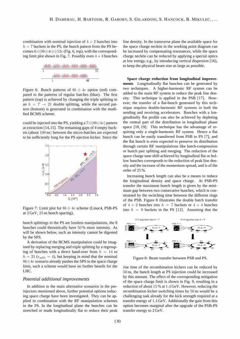
combination with nominal injection of4 + 2 bunches intoh = 7 buckets in the PS, the bunch pattern from the PS be-comes6⊗(8b⊕4e)⊕12e (Fig. 6, top), with the correspond-ing limit plot shown in Fig. 7. Possibly even4+ 3 bunches
Figure 6: Bunch patterns of8b ⊕ 4e option (red) com-pared to the patterns of regular batches (blue). The firstpattern (top) is achieved by changing the triple splitting toan h = 7 → 21 double splitting, while the second pat-tern (bottom) is generated in combination with the modi-fied BCMS scheme.
could be injected into the PS, yielding a7⊗(8b⊕4e) patternat extraction [14,15]. The remaining gaps of 4 empty buck-ets (about100ns) between the micro-batches are expectedto be sufficiently long for the PS ejection kicker. Since the
Figure 7: Limit plot for8b ⊕ 4e scheme(Linac4, PSB-PSat2GeV,25ns bunch spacing).
bunch splittings in the PS are lossless manipulations, the 8bunches could theoretically have50% more intensity. Aswill be shown below, such an intensity cannot be digestedby the SPS.
A derivation of the BCMS manipulation could be imag-ined by replacing merging and triple splitting by a regroup-ing of bunches with a direct hand-over fromh = 14 toh = 21 (rsplit = 4), but keeping in mind that the nominal8b⊕4e scenario already pushes the SPS to the space chargelimit, such a scheme would have no further benefit for theLHC.
Potential additional improvements
In addition to the main alternative scenarios in the pre-injectors mentioned above, further potential options reduc-ing space charge have been investigated. They can be ap-plied in combination with the RF manipulation schemesin the PS. In the longitudinal plane the bunches can bestretched or made longitudinally flat to reduce their peak
line density. In the transverse plane the available space forthe space charge necktie in the working point diagram canbe increased by compensating resonances, while the spacecharge necktie can be reduced by applying a special opticsat low energy, e.g., by introducing vertical dispersion [16],to keep the physical beam size as large as possible.
Space charge reduction from longitudinal improve-ments Longitudinally flat bunches can be generated bytwo techniques. A higher-harmonic RF system can beadded to the main RF system to reduce the peak line den-sity. This technique is applied in the PSB [17]. How-ever, the transfer of a flat-bunch generated by this tech-nique requires double-harmonic RF systems in both thesending and receiving accelerators. Bunches with a lon-gitudinally flat profile can also be achieved by depletingthe central part of the distribution in longitudinal phasespace [18, 19]. This technique has the advantage of re-quiring only a single-harmonic RF system. Hence a flatbunch can be easily transferred from PSB to PS [7], andthe flat bunch is even expected to preserve its distributionthrough certain RF manipulations like batch-compressionor bunch pair splitting and merging. The reduction of thespace charge tune shift achieved by longitudinal flat or hol-low bunches corresponds to the reduction of peak line den-sity and the increase of the momentum spread, and is of theorder of25%.
Increasing bunch length can also be a means to reducethe longitudinal density and space charge. At PSB-PStransfer the maximum bunch length is given by the mini-mum gap between two consecutive bunches, which is con-strained by the switching time between the different ringsof the PSB. Figure 8 illustrates the double batch transferof 4 + 2 bunches intoh = 7 buckets or4 + 4 bunchesinto h = 9 buckets in the PS [12]. Assuming that the
Figure 8: Beam transfer between PSB and PS.
rise time of the recombination kickers can be reduced by50ns, the bunch length at PS injection could be increasedby this amount. The effect of the corresponding mitigationof the space charge limit is shown in Fig. 9, resulting in areduction of about15% at1.4GeV. However, reducing therecombination kicker switching times by50ns would be achallenging task already for the kick strength required at atransfer energy of1.4GeV. Additionally the gain from thisoption becomes marginal after the upgrade of the PSB-PStransfer energy to2GeV.
H. DAMERAU, H. BARTOSIK, R. GAROBY, S. GILARDONI, S. HANCOCK, B. MIKULEC, . . .
130

Figure 9: Brightness limit improvement of longer buncheswith faster recombination kickers (Linac4, PSB-PS at1.4GeV,25ns bunch spacing).
Space charge reduction from transverse improve-ments Studies to compensate lattice resonances withskew sextupole magnets for LHC-type beams in the PShave started in 2013, following the installation of 4 sex-tupole magnets during the winter stop. At the nominal(fractional) working point ofqx = 0.21 and qy = 0.24the closest 4th order resonance is excited by space chargeitself and cannot be easily compensated. Successful com-pensation of the2qx + qy = 1 and3qy = 1 resonance lineshas nonetheless been demonstrated [20] and a study pro-gram with the objective of simultaneous compensation ofmultiple resonances will continue after LS1.
Space charge effects may also be reduced by maximiz-ing the physical beam size at low energies. The regularlattice of the PS features 10 lattice super-periods with 10magnet units each [21]. The vertical dispersion,Dy, isideally zero all around the ring. Introducing perturbationsusing the already existing skew quadrupoles, an irregularlattice with non-zero vertical dispersion (fully coupled op-tics) can be obtained [16]. Beta functions and dispersionaround the PS circumference for an extreme case are plot-ted in Fig. 10. This would ideally provide a Laslett tune-
Figure 10: Lattice functions for the case of an extreme op-tics with vertical dispersion.
shift reduction of a factor of 1.5 in both planes. It is impor-tant to point out that extensive upgrades of various skew
quadrupolesand their power converters would be requiredto reach such a configuration. As the optics functions arevery irregular, simulations including space charge shouldbe performed; especially the sensitivities with respect tocoupling resonances remain to be studied. Assuming thatno show-stoppers are identified by these simulations, firstbeam studies to evaluate the potential benefit of non-zerovertical-dispersion optics can be initiated after LS1.
Alternatives for special cases of limited upgrades
In the unlikely case of Linac4 connection before the up-grade of the PSB-PS transfer energy, space charge on thePS flat-bottom will become the most stringent limitationin the injector chain, essentially independent from the RFmanipulation scheme. Figure 11 presents a limit plot for aninjection energy into the PS of1.4GeV. The brightness de-liverable by the PSB and acceptable for the SPS becomesalmost twice the brightness which the PS can digest andalmost nothing would be gained for LHC-type beams withLinac4.
Figure 11: Limit plot for double-batch injection of 8bunchesinto h = 9 and subsequent generation of 64 bunchbatches (Linac4, PSB-PS at1.4GeV,25ns bunch spacing).The bunches are double split on the flat-bottom and againtwice on the flat-top,rsplit = 8 [5].
To profit in this case from the significantly higher bright-ness with Linac4, single-batch transfer of 4 bunches intoh = 5 buckets in the PS has been suggested [22]. As be-comes clear from Fig. 12, the space charge limit in the PSmatches again with the brightness deliverable by the PSBwith Linac4.
After injection, each bunch is double split twice, result-ing in 16 bunches at harmonich = 20. Following a singleharmonic number hand-over toh = 21 (Fig. 13), the 16bunches are accelerated to the flat-top where each of thempasses through the usual quadruple splitting (rsplit = 16),hence the PS produces batches of 64 bunches. Theseshorter batches would reduce the total number of bunchesin the LHC by only about3%, but with reduced filling timethanks to the one third shorter cycle in the PS.
The lowest harmonic number,h = 5 (2.18MHz), re-
LIU: EXPLORING ALTERNATIVE IDEAS
131

Figure 12: Limit plot for single-batch injection intoh = 5and subsequent generation of 64 bunch batches (Linac4,PSB-PS at1.4GeV,25ns bunch spacing).
Figure 13: Single-batch injection of 4 bunches from thePSBinto h = 5 in the PS.
quired with this alternative scheme at injection, is belowthe lower limit of the frequency range of the main RF cavi-ties, but the development of a dedicated or the modificationof an existing cavity could be envisaged.
ALTERNATIVE SCHEMES IN THE SPS
In the framework of the LIU upgrades the integer work-ing point of the SPS has recently been moved fromQh/Qv = 26 to 20, operating with a new low transi-tion energy optics which significantly improves longitudi-nal and transverse beam stability for LHC-type beams, butrequires higher RF voltage [23]. The future baseline up-grades include measures against e-cloud instabilities anda major upgrade of the main200MHz RF system of theSPS. The latter mainly foresees the regrouping of the trav-eling wave cavities into four 3-section and two 4-sectioncavities [24, 25], the installation of two additional1.6MWRF power amplifiers and an upgrade of the beam controlsystem.
Beyond this baseline, even further splitting to a larger
numberof shorter cavities has been considered, as well asthe effect of the8b⊕4e scheme or a possible200MHz mainRF system in the LHC. As part of the upgrade baseline,the successful mitigation of electron cloud instabilities byamorphous carbon coating [26] or scrubbing of the SPSbeam pipe is assumed.
RF power considerations at extraction to LHC
At transfer to the LHC, the200MHz RF system in theSPS has to provide sufficient RF voltage to keep the bunchlength below1.7ns (4σGaussian fit) to fit into the2.5nslong buckets of the LHC. Two effects determine the RFvoltage and power requirements which are beam loadingand longitudinal beam stability.
At fixed maximum RF power the voltage generated bythe traveling wave accelerating cavities of the SPS [27] de-creases with increasing beam intensity [28] due to beamloading. This voltage decrease at given RF power is il-lustrated for different RF system configurations in Fig. 14.The grey curve shows the voltage decrease for the present
Figure 14: Beam loading (25ns bunch spacing) and sin-gle bunch stability limits for various arrangements of the200MHz cavities [25].
cavity configuration (two 4-section and two 5-section cavi-ties) and an RF power of0.7MW per cavity. Pulsing the RFamplifiers with the revolution frequency following the up-grade of the LLRF system allows a power increase to about1.05MW per amplifier (blue curve). Following the LIUbaseline upgrade, two new transmitters with an RF powerof 1.6MW each will become available. Together with theplanned re-grouping of the cavity sections to four 3-sectioncavities and two 4-section cavities, the available voltage isincreased significantly (red curve). Thanks to the additionof two more sections (in total 20 instead of 18 section),low- and high-intensity beams will profit from the baselineupgrade.
Alternatively, the same number of total cavity sectionscan be assembled to more but shorter cavities. The blackcurves of Fig. 14 show the available RF voltage for extremecases of four 3-section with four 2-section cavities (two ad-ditional 1.6MW RF transmitters compared to the baselineupgrade), as well as ten 2-section cavities (four additionaltransmitters). Essentially no further voltage gain can beachieved for lower intensity beams.
H. DAMERAU, H. BARTOSIK, R. GAROBY, S. GILARDONI, S. HANCOCK, B. MIKULEC, . . .
132

To finally estimate the voltage requirements at a fixedbunch length at transfer to LHC, longitudinal instabili-ties must be taken into account. Considering only thevoltage reduction by potential-well distortion (PWD) andthe single-bunch instability due to loss of Landau damp-ing (LD), a scaling law for the minimum longitudinal emit-tance emittance assuring stability can be derived [29, 30].Assuming constant bunch lengthτ , it can be shown thatthe RF voltage must increase proportionally to the bunchintensity. The nominal LHC beam with25ns with an in-tensity of 1.3 · 1011 ppb and a longitudinal emittance ofεl ≃ 0.35eVs can be taken as a reference case for the lin-ear increase of RF voltage with intensity. Measurementshave shown that it is indeed close to the longitudinal sta-bility limit on the flat-top in the SPS [25]. Combining theintensity dependent voltage requirement with the availablevoltage at fixed RF power results in an estimation of themaximum intensity for the different RF system configura-tions (Fig. 14).
The grey point again indicates the present cavity con-figuration (two 4-section and two 5-section cavities).With a maximum voltage of about7MV an intensity of1.3 · 1011 ppb has been achieved on the flat-top. Upgradingthe low-level RF system to operate the cavities in pulsedmode increases the available RF power per amplifier from0.7MW to 1.05MW, allowing a maximum intensity of1.5 · 1011 ppb. A major improvement will be introducedby the re-grouping of the cavities as foreseen within theLIU baseline. Without any increase of bunch length, an in-tensity of2.0 · 1011 ppb can be obtained. It is important topoint out that the contribution from loss of Landau dampingto the gradient of the line in Fig. 14 scales withε−5/2
l andis directly proportional to the broadband impedance,Z/n.Permitting only10% longer bunches at transfer to the LHCincreases the maximum intensity estimate to2.5 ·1011 ppb.
The effect of further shortening the RF cavities is shownin Fig. 15, indicating the maximum achievable intensity perbunch versus total RF power. Clearly, the step for the base-
Figure 15: Total RF power versus maximum bunch inten-sity (25ns bunch spacing). The colours correspond to thoseof Fig. 14.
line upgrade from two 4-section and two 5-section to four3-section and two 4-section cavities, adding two1.6MWamplifiers, results in the most efficient intensity increase.
Thenext step to four 2-section and four 3-section cavities,requiring two more additional power amplifiers, gains onlyhalf of the previous step. Moving to an extreme case of ten2-section cavities demands for excessive RF power with lit-tle effect on maximum intensity per bunch.
8b⊕4e bunch pattern schemes At fixed bunch inten-sity, the line density averaged over300ns is reduced by2/3using the8b⊕4e bunch pattern schemes. With a filling timeof the RF cavities in the SPS of about twice that duration,one can expect50% higher bunch intensity for the samevoltage as illustrated in Fig. 16. However, as potential well
Figure 16: Improvements with the 8b+4e bunch patternscheme(25ns bunch spacing).
distortion and loss of Landau damping are single-buncheffects, no scaling is applied to the instability line (withrespect to Fig. 14). The potential gain with the8b ⊕ 4eschemes is thus below50% and to reach a bunch intensityof 3 · 1011 ppb with the baseline RF upgrade would requirean impedance reduction by approximately50% (Fig. 16,blue shaded area).
Proof-of-principle beam tests of the8b ⊕ 4e scheme inthe whole accelerator complex will become possible afterLS1 at reduced performance level to evaluate its potentialgain with respect to the nominal filling scheme.
200 MHz RF system in the LHC The major con-straint of short bunches at transfer from SPS to LHC isrelaxed with a200MHz RF system in the LHC. Furtherbenefits of a lower frequency main RF system in the col-lider are discussed in [15]. While the beam loading curvesremain unchanged (Fig. 17), the single bunch instabili-ties are well suppressed thanks to the strong dependenceof the loss of Landau damping on longitudinal emittance.Assuming a longitudinal emittance of1eVs, the RF voltagefor matched transfer into a200MHz/3MV bucket in theLHC requires an intensity independent voltage of7.5MVin the SPS. In conjunction with the baseline RF upgradethe maximum intensity per bunch on the SPS flat-top is es-timated at above2.5·1011 ppb, clearly highlighting the ben-efit of a200MHz RF system in the LHC for the injectors.
LIU: EXPLORING ALTERNATIVE IDEAS
133

Figure 17: Larger longitudinal emittance anticipating a200MHz RF system in the LHC (25ns bunch spacing).
Performance during acceleration in the SPS
Next to the constraints at transfer to the LHC, the avail-able RF power also limits the maximum intensity duringthe acceleration ramp. Assuming the present cavity config-uration and magnetic cycle for LHC-type beams, the bucketarea during the first part of the cycle is limited toAb =0.6eVs at an intensity of, e.g.,1.2 · 1011 ppb (Fig. 18).Without reducing the ramp rate and hence stretching the
Figure 18: RF power and resulting bucket area along theLHC cycle in the SPS for the present configuration with abunch population ofNb = 1.2 ·1011 (25ns bunch spacing).The different blue curves show the RF power for the 4-section and 5-section cavities.
acceleration cycle, this leaves little margin for further in-tensity increase.
Already the baseline RF upgrade will provide a largerbucket area (Ab = 0.75eVs at the start of acceleration withmargin for increase during the cycle) for an intensity of2.3 · 1011 ppb (Fig. 19), beyond the limitation at transfer tothe LHC discussed above. In combination with the8b⊕ 4escheme, an intensity of up to3.0 · 1011 ppb is expected tobe accelerated, thanks to the50% reduction of the averageline density. Clearly, the baseline RF upgrade remains in-dispensable to profit from the benefit of a new200MHz RFsystem in the LHC.
Extending the upgrade to four 2-section cavities andfour 3-section cavities (in total four new1.6MW RF am-plifiers), the intensity reach for the25ns beam could be
Figure 19: RF power and resulting bucket area along theLHC cycle in the SPS for the baseline upgrade configura-tion with a bunch population ofNb = 2.3 · 1011 (25nsbunch spacing). The blue traces indicate the power of anew amplifier connected to a 4-section cavity (top) and anexisting amplifier connected to 3-section cavity (bottom).
pushed above3 · 1011 ppb. Figure 20 illustrates RF powerand bucket area for a bunch population of3.2 · 1011 ppb.
Figure 20: RF power and resulting bucket area along theLHC cycle in the SPS for in total 8 cavities (4 additionalpower plants) configuration with a bunch population ofNb = 3.2·1011 (25ns bunch spacing). The two blue curvesshow again the power with new (top) and existing (bottom)RF amplifiers.
As shown above, the baseline upgrade of the200MHzincluding the re-grouping of cavity sections and the con-struction of two new power amplifiers represents a majorgain in bunch intensity during acceleration, as well as attransfer to the LHC. Alternative options to further split thecavities, and add even more RF power, may be beneficial,but the incremental gain becomes less significant.
Transverse improvements
In terms of alternative improvements in the transverseplane, the SPS offers less possibilities and flexibility thanthe pre-injectors. Firstly, similar to the increase of the ex-traction energy of the PSB, the PS may have a small marginto extract above the present (total) energy of26GeV. At its
H. DAMERAU, H. BARTOSIK, R. GAROBY, S. GILARDONI, S. HANCOCK, B. MIKULEC, . . .
134

initial commissioning in the late 1950s, a flat-top energy of28GeV had been reached [31], but such beams were notextracted. Even though the PS ejection elements, as wellas the SPS injection elements have not been designed forthis high energy, the LHC-type beams have small trans-verse emittances compared to fixed target beams. Henceslightly too small kick angles at PS ejection and SPS injec-tion are not expected to cause losses and can most likelybe corrected. Raising the transfer to28GeV results in aspace charge tune shift reduction in the SPS of15% withan immediate gain for all schemes limited by the SPS spacecharge. First studies to extract beams above26GeV fromthe PS are planned for 2014.
Secondly, instead of moving both horizontal and verticalinteger tunes fromQh/Qv = 26 to 20, a split-tune opticswith Qh = 20 andQv = 26 has been proposed [32]. Fig-ure 21 illustrates the normalized space charge tune shiftsat SPS injection versus transverse emittance. The most fa-
Figure 21: Normalized horizontal and vertical space chargetune shift versus transverse emittance for Q20, Q26 andsplit-tune optics.
vorable situation can be achieved with the split-tune optics.Additionally, the kick strength required at injection is re-duced when moving fromQv = 20 back toQv = 26,leaving some margin for the injection at energies above26GeV. Transverse instability thresholds can be slightlyincreased by the reduction of the vertical beta function forQv = 26.
Finally, as in the PS, a lattice with non-zero verticaldispersion could be envisaged in the SPS. However, im-portant changes to the cabling and the supply of the skewquadrupole magnets, which are presently grouped in fami-lies, would be required.
CONCLUSIONS
No magic alternative to the present baseline upgrades,including Linac4, the increase of the PSB-PS transfer en-ergy to 2GeV and a major RF upgrade in the SPS, hasbeen identified. The flexibility of the pre-injectors allows
an important number of different production schemes toincrease bunch intensity and beam brightness. Some ofthese schemes deliver sufficiently high brightness to pushthe SPS to its space charge limit.
The acceleration and transfer to LHC of bunches withlarger longitudinal emittance and higher intensity in theSPS will become possible following the major RF upgrade.A new RF system at200MHz in the LHC would addition-ally have beneficial effects for the injectors as it furtherrelaxes the constraints on bunch length and longitudinalemittance at transfer from the SPS, estimating a maximumbunch intensity beyond2.5 · 1011 ppb and shifting possi-ble limits to the lower energy part of acceleration. How-ever, the brute-force approach of adding even more thantwo 1.6MW power amplifiers has only limited reach as theabsolute intensity gain when moving from 6 to 8 cavities ishalf of the extra intensity reach when moving from 4 to 6cavities.
A number of interesting alternatives have been identifiedwhich will be accessible to machine development studiesafter LS1 to validate their potential benefits:
• PSB: hollow bunches,
• PS: flat or hollow bunches, special flat-bottom optics,PBC,8b⊕ 4e schemes, PS-SPS transfer energy above26GeV,
• SPS: split-tune optics, higher intensity at transfer tothe LHC with slightly longer bunches.
Even more combinations of the various alternatives can beimagined.
Finally, the flexibility of producing a wide range of beamparameters represents an important asset of the injectorchain which allows to quickly react to requests from theLHC in case of unforeseen issues. The8b ⊕ 4e schemeis one example of an alternative in case of persistent elec-tron cloud issues in the LHC with25ns bunch spacing afterLS1. This flexibility of CERN’s injector chain should bepreserved in the future.
ACKNOWLEDGEMENTS
The authors would like to thank Gianluigi Ar-duini, Theodoros Argyropoulos, Michael Benedikt,Thomas Bohl, Christian Carli, Brennan Goddard,Werner Herr, Wolfgang Hofle, Eric Montesinos, Luc Ser-meus, Helga Timko and Raymond Wasef for discussionsand for providing information.
APPENDIX
Many alternative options have already been studiedby numerous authors and have therefore not been re-considered in the present report. Table 3 gives a non-exhaustive list of these alternative options.
LIU: EXPLORING ALTERNATIVE IDEAS
135

Table 3: Non-exhaustive list of further alternative optionsstudied by other authors.
Alternative scheme Remark Reference
PSB
Vertical painting at PSB injection with Linac4Replacement of the PSB by a Rapid Cycling Synchrotron
Minor improvementStudy not continued
[33][34]
PS
H− injection from SPL-like Linac into the PS40MHz-based main RF systemSeparated function lattice with30GeV energy
Together with40MHz RFNeeds Linac for40MHz structureEssentially new accelerator in PS tunnel
[4,35,36][4][37]
SPS Low frequency (40MHz capture cavity in the SPS)
Splitting or mergingSlip stacking to increase bunch intensity
Issues with beam stabilityWould require low-frequency cavityIssues with beam loading andεl
[38]
[39]
REFERENCES
[1] R. Garoby et al., “Plans for the Upgrade of the LHC Injec-tors”, IPAC2011, San Sebastian, Spain, 2011, p. 2517-2519.
[2] H. Bartosik et al., “Can we Ever Reach the HL-LHC Re-quirements with the Injectors (LIU)?”,these proceedings.
[3] M. Benedikt et al., “The PS Complex as Proton Pre-Injectorfor the LHC”, CERN 2000-03, CERN Geneva, Switzerland,2000.
[4] C. Carli, “Other Scenarios for a Partial Upgrade of the In-jector Complex”, Chamonix 2010 LHC Performance Work-shop, Chamonix, France, pp. 247-252, 2010.
[5] C. Carli et al., “Alternative/complementary Possibilities”,Chamonix 2011 LHC Performance Workshop, Chamonix,France, pp. 361-367, 2011.
[6] H. Bartosik et al., “Performance Potential of the Injectorsafter LS1”, Chamonix 2012 LHC Performance Workshop,Chamonix, France, pp. 268-275, 2012.
[7] G. Rumolo et al., “Expected Performance in the Injectors at25 ns without and with LINAC4”,these proceedings.
[8] L. Sermeus,private communication, 2013.
[9] R. Garoby, “Analysis of Batch Compression in thePS”, High Intensity Proton Working Group Meet-ing (HIP), CERN, Geneva, Switzerland, 2003,https://ab-div.web.cern.ch/ab-div/Projects/
hip/Presentations/HIP-10Dec03-RGaroby.ppt.
[10] R. Garoby, “New RF Exercises Envisaged in the CERN-PS for the Antiprotons Production Beam of the ACOL Ma-chine”, PAC1985, Vancouver, British Columbia, Canada,pp. 2332-2334, 1985.
[11] S. Hancock, “Batch Compression Makes Sense”,unpub-lished presentation at LIU Day 2013, CERN, Geneva,Switzerland, 2013,http://indico.cern.ch/getFile.py/access?contribId=9&sessionId=2&resId=
1&materialId=slides&confId=238152.
[12] H. Damerau et al., “RF Manipulations for Higher BrightnessLHC-type Beams”, IPAC2013, Shanghai, China, pp. 2600-2602, 2013.
[13] O. Domınguez et al., “Electron Cloud Studies for Alterna-tive Train Configurations and Bunch Spacings at the HL-LHC”, CERN-ATS-Note-2013-036 TECH, CERN, Geneva,Switzerland, 2013.
[14] H. Bartosik, H. Damerau, B. Goddard, G. Rumolo et al.,discussions during RLIUP.
[15] R. Tomas et al., “HL-LHC: Exploring alternative ideas”,these proceeding.
[16] Y. Papaphilippou,private communication, 2013.
[17] A. Hofmann, F. Pedersen, “Bunches with Local Elliptic En-ergy Distributions”, PAC1979, San Francisco, California,U.S.A., pp. 3526-3528, 1979.
[18] R. Garoby, S. Hancock, J. L. Vallet, “PS Machine Develop-ment Report”, PS/RF/Note 92-8, CERN, Geneva, Switzer-land, 1992.
[19] C. Carli, “Creation of Hollow Bunches using a doubleharmonic RF System”, CERN/PS 2001-073 (AE), CERN,Geneva, Switzerland, 2001.
[20] R. Wasef et al., “Resonance Compensation”,unpublishedpresentation in LIU-PS meeting, CERN, Geneva Switzer-land, 2013, https://indico.cern.ch/getFile.
py/access?contribId=0&resId=1&materialId=
slides&confId=241210.
[21] R. Cappi et al., “Optics Studies in the CERN Pro-ton Synchrotron: Linear and Nonlinear Modelling UsingBeam Based Measurements”, PAC2003, Portland, Oregon,U.S.A., pp. 2913-2915, 2003.
[22] S. Hancock,private communication, 2013.
[23] Y. Papaphilippou et al., “Operational Performance of theLHC Proton Beams with the SPS Low Transition EnergyOptics”, IPAC2013, Shanghai, China, pp. 3945-3947, 2013.
[24] E. Shaposhnikova, “SPS Collective Effects and Lim-itations”, LIU-2011 Event, CERN, Geneva, Switzer-land, 2011, https://indico.cern.ch/getFile.
py/access?contribId=17&resId=1&materialId=
slides&confId=160434.
[25] E. Shaposhnikova, “SPS Intensity Limitation Without the200 MHz Upgrade”,unpublished presentation in LIU-SPSBeam Dynamics Working Group meeting, CERN, Geneva,2013, http://paf-spsu.web.cern.ch/paf-spsu/
meetings/2013/m11-07/SPSRF_US1_BD.pptx.
[26] J. M. Jimenez, “Electron Clouds in the SPS: Progress in theAnalysis of Cures/mitigation Measures and Potential Sched-ule of Implementation”, Chamonix 2011 LHC PerformanceWorkshop, Chamonix, France, pp. 355-358, 2011.
H. DAMERAU, H. BARTOSIK, R. GAROBY, S. GILARDONI, S. HANCOCK, B. MIKULEC, . . .
136
[27] G. Dome, “The SPS Acceleration System Traveling WaveDrift Tube Structure for the CERN SPS”, LINAC76, ChalkRiver, Ontario, Canada, pp. 138-147, 1976.
[28] T. Bohl, “The 200 MHz Travelling Wave Cavities in theSPS”, Chamonix 2000 SPS and LEP Performance Work-shop, Chamonix, France, pp. 58-60, 2000.
[29] E. Shaposhnikova, “Longitudinal Stability of the LHCBeam in the SPS”, SL-Note-2001-031 HRF, CERN,Geneva, Switzerland, 2001.
[30] E. Shaposhnikova, “Longitudinal Beam Parameters DuringAcceleration in the LHC”, LHC Project Note 242, CERN,Geneva, Switzerland, 2000.
[31] J. B. Adams, “The CERN Proton Synchrotron”, Nature, Vol.185, pp. 568-572, 1960.
[32] H. Bartosik et al., “Increasing Instability Thresholds in theSPS by Lowering Transition Energy”, IPAC12, New Or-leans, Louisiana, U.S.A., pp. 3096-3098, 2012.
[33] C. Bracco et al., “Studies of Transverse Painting for H−
Injection in the PSB”, IPAC11, San Sebastian, Spain, pp.3544-3546, 2011.
[34] K. Hanke et al., “PS Booster Energy UpgradeFeasibility Study First report”, EDMS Documentno. 1082646 v.3, CERN, Geneva, Switzerland,2010, https://edms.cern.ch/file/1082646/3/
PSBUpgrade_Feas_Study_v3.pdf.
[35] R. Garoby, M. Vretenar, “Proposal for a 2 GeV Linac Injec-tor for the CERN PS”, PS/RF/Note 96-27, CERN, Geneva,Switzerland, 1996.
[36] M. Vretenar et al., “Report of the Study Group on a Super-conducting Proton Linac as a PS Injector”, CERN/PS 98-063 (RF-HP).
[37] Y. Papaphilippou,private communication, 2013.
[38] E. Shaposhnikova, “Low Frequency RF System in theSPS?”, unpublished presentation in SPSU-BD workinggroup meeting, CERN, Geneva, Switzerland, 2011.
[39] T. Argyropoulos , E. Shaposhnikova, “Possible Increase ofBunch Intensity in the SPS for HL-LHC”,unpublished pre-sentation in LIU & HL-LHC brainstorming meeting, Crozet,France, 2011.
LIU: EXPLORING ALTERNATIVE IDEAS
137