Embed Size (px)
Citation preview

9
CHAPTER 2
LITERATURE REVIEW
2.1 Introduction
In recent years, considerable work has been done to the development of miniature
closed cycle refrigerators. These devices find wide applications in the cooling of
electronic components and sensors, which typically dissipate less than few Watts of heat
and operate at temperatures in the range of 150 to 4 K or below. They are generally called
cryocoolers.
The demand for increasing numbers and types of miniature cryogemc
refrigeration systems has been spurred, not only by ambitious space missions but also by
the need for helium refrigeration systems for applications like super conductivity. This
resulted in the development of regenerative refrigerators, operating on modified Solvay,
Gifford-McMahon, reversed Stirling, pulse tube etc. The choice of one over the other
depends on many factors like cost, weight, volume, vibration, reliability, efficiency etc.
The principal requirements for such applications include adequate refrigeration at
required temperatures with low power input, long life, reliable and maintenance free
operation with minimum vibration and noise, compactness and lightweight. Unlike the
Stirling and Gifford McMahon refrigerators, pulse tube refrigerators have no moving
parts at the cold end. The absence of moving parts at the cold region has allowed it to
solve some problems associated with cryocoolers in different applications such as
vibration and reliability.
2.2 Pulse tube refrigerators (PTRs)
Initially, operating principles of PTRs were not well understood. The oscillatory
flow inside the pulse tube and associated complex thermodynamic and heat transfer
processes are responsible for it. The level of understanding grew gradually; modifications
and improved designs yielded much improved efficiencies. It has now become one of the
most efficient cryocooler for a given size.

10
The first report of pulse tube refrigeration by W.E. Gifford and R.C. Longsworth [I]
in 1964 was enough to excite the researchers due to its potential for high reliability and
simplicity. In 1984, Mikulin et aP I] published their innovative modification of the basic
pulse tube refrigerator, called orifice pulse tube refrigerator. The researchers concentrated
their efforts to improve the performance of the pulse tube refrigerators in many ways. As
a result, different configurations of pulse tube refrigerators have been evolved and
efficiency has improved rapidly. Several representative configurations are detailed in this
section, explaining their cooling mechanisms and characteristics briefly. The various
developments took place in the area of PTRs since its invention in 1964, are also
presented in chronological manner.
2.2.1. Basic pulse tube refrigerator (BPTR)
The BPTR consists of a pressure wave generator, after cooler, regenerator, cold
end heat exchanger (CHX), hot heat exchanger (HHX) and a thin tube called pulse tube.
The periodic pressurization and depressurization produced by the pressure source causes
the gas to flow back and forth through the regenerator and pulse tube. The schematic
diagram of BPTR and its cooling mechanism is shown in figure 1.1.
Gifford et al [3] explained the cooling mechanism in BPTR by the surface heat
pumping theory. During the pressure build up period, the valve admits high-pressure gas
through the regenerator, where it is cooled to the cold end temperature. There is some gas
present in the tube at the beginning of the cycle. The entering gas acts as a gas piston and
compresses the gas present in the pulse tube. The gas piston pushes the gas to the far end
of the tube, where a heat exchanger is employed as a heat sink. The temperature of the
gas will come down to that of the hot end heat exchanger (Th)' Then the high-pressure gas
is allowed to expand during the exhaust phase of the cycle to a very low temperature (Tc),
thus producing refrigeration.
Although, the heat exchange between the gas and the wall takes place along the
length of the pulse tube, it is assumed that heat rejection takes place only in the region of
hot end heat exchanger. After the expansion takes place adiabatically, the temperature of
the gas becomes lower than the wall temperature. So, heat will be transferred from the

Compressor Regenerator Pulse tube
11
.Position
Figure 2.1 Temperature - position diagram of a gas element in BPTR
wall to the gas. However, when the gas parcel enters the cold end heat exchanger, its
temperature is lower than the room temperature and heat is absorbed from the heat
exchanger producing cooling power. The net result of this effect is that heat is extracted
from the cold end exchanger and rejected at the hot end exchanger. Due to this, the cold
end heat exchanger and regenerator will cool down a bit and the next cycle starts at a
slightly lower temperature. The cycle repeats itself to cool down the heat exchanger
further more.

12
2.2.2 Orifice pulse tube refrigerator (OPTR)
In 1984, at the Moscow Bauman Technical Institute Mikulin and co-workers[II]
introduced an orifice inside the pulse tube near the hot end, to expand the gas into a buffer
volume and achieved a lower temperature of l05K with air as working fluid. In 1985
Radebaugh et at [16] placed the orifice outside the pulse tube refrigerator after the hot end
heat exchanger. This configuration was called Orifice Pulse Tube Refrigerator (OPTR)
The schematic diagram of OPTR is shown in figure 2.2.
l- I-
~-{X)-- 4 7I-
6
1 5 2 3 3
Figure 2. 2. Schematic diagram of orifice pulse tube refrigerator.
1. Compressor 2. Regenerator 3. Heat Exchangers 4. Pulse Tube5. After cooler 6.Orifice 7.Reservoir
The refrigeration cycle of an OPTR begins as the piston moves forward and the
gas passes through the regenerator and is cooled to the cold end temperature. The gas is
compressed adiabatically, as it flows through the regenerator, cold end heat exchanger
and pulse tube towards the hot end heat exchanger. During the high-pressure period, heat
is rejected from the system in the hot end heat exchanger. In the OPTR, the gas is further
cooled by adiabatic expansion due to flow through orifice. The compressor piston then
moves back and gas flows out of the tube back through the regenerator. Gas in the tube is
cooled due to adiabatic expansion and gas flows through the cold end heat exchanger and
absorbs heat from the space to be cooled. In an OPTR, the refrigeration is enhanced by
the additional expansion of the gas in the pulse tube due to the gas flow out of the tube
through the orifice. The gas pressure in the reservoir volume remains at an average

13
pressure and the pressure in the pulse tube varies between maximum and minimum
values. The cycle results in an average enthalpy flow from the cold end to the hot end,
which establishes a constant temperature gradient in the tube and provides continuous
refrigeration effect, as shown in figure 2.3. As seen in figure 2.3, in a BPTR the lowest
temperature to which the gas can be cooled after compression is the wall temperature of
the tube or the temperature of the cooling medium. But in an OPTR, due to the expansion
through orifice, the gas can be cooled to a temperature lower than that can be attained in a
BPTR.
The disadvantage of an OPTR is that, a large amount of compressed gas that
produces no actual refrigeration must flow through the regenerator. This decreases the
refrigeration power per unit of compressed mass and therefore increases the regenerator
loss. The larger the mass flows rate in the regenerator, the smaller the effectiveness of
regenerator, and larger will be the pressure drop. Both these effects reduce the
performance of an OPTR.
Pulse Tube
Heat transfer
.......... -.4
3
Orifice
2 ..4--~Walltemperature
/J/, 3
1 f":;"" BPTR
4
Figure 2.3 Temperature Vs position for gas elements ofOPTR and BPTR

14
2.2.3 Double inlet pulse tube refrigerator (DIPTR)
The double inlet pulse tube refrigerator shown in figure 2.4 was invented by
Zhu and his co-workers[33] and meant a further improvement of performance of the pulse
tube refrigerator. According to Zhu, in an OPTR the actual cooling takes place during the
gas flow through the orifice. The compression and expansion are necessary to create the
pressure difference between pulse tube and reservoir. But they don't make any
contribution towards the cooling power. On the other hand, the gas has to flow via the
regenerator to build up the pressure and to decrease the pressure in the pulse tube. This
part ofthe mass flow rate called 'the useless mass flow rate', flow through the regenerator
and increase the heat transfer load on the regenerator. The quantity of this part of the gas
will increase with decrease in refrigeration temperature, increase in the pressure ratio,
increase in the volume of the pulse tube and hot heat exchanger, thus limiting the lower
refrigeration temperature obtained in an OPTR.
8
l- I-
-[)f<}-- 4 7l- I-
6I 5 2 3 3
Figure 2.4 Schematic diagram ofdouble inlet pulse tube refrigerator
I. Compressor 2. Regenerator 3 Heat Exchangers
5. After cooler 6 Orifice 7 Reservoir
4 Pulse Tube
8 By pass Valve
By reducing the flow through the regenerator, the pressure rise and decrease in
mass flow could still be maintained via a short cut between compressor and pulse tube,
called the double inlet pulse tube refrigerator. Thus the losses inside the regenerator are
reduced considerably.

15
2.2.4 Multi stage pulse tube refrigerator
It is really impossible to reach very low temperature in a single stage pulse tube
refrigerator. So the pulse tube can be staged, with one pulse tube used to pre cool the
other. Gifford and Longsworth[2] had already proposed to use a two stage or three stage
basic pulse tube cooler to achieve lower temperatures.
In 1993 Matsubara et al [53] were the first to reach temperatures below 4K with a
three-stage pulse tube refrigerator as shown in figure 2.5. Their set up consists of one
regenerator, split up into three stages, by connecting three pulse tubes with their own hot
heat exchanger orifice, double inlet and reservoir volume at room temperature. The gas
enters and leaves the system via the after cooler on top of the first stage regenerator. The
first stage regenerator and pulse tube create cooling power to pre-cool the gas entering the
second stage regenerator. So the second stage creates cooling power at a lower
temperature than the first stage, to pre-COOl the third stage regenerator. In this way, the
third stage is able to reach temperature below 4K.
FirstStage
SecondStage
ThirdStage
Figure.2.5 Schematic diagram of a three-stage pulse tube refrigerator

16
2.2.5. Four valve pulse tube refrigerator
In 1992, Matsubara et al[SI] introduced a four-valve pulse tube refrigerator
as shown in figure 2.6. This kind of pulse tube does not have any reservoir volume. This
is an advantage especially in the case of multistage coolers. It improves the compactness
of the arrangement.
In addition to the high and low pressure switching valves, two more switching
valves are used to control the gas flow in the hot end of the pulse tube. The reservoir
volume and double inlet valves are eliminated in that case. This principle can be extended
to multistage system where two additional switching valves are needed for each stage.
The machine can be made more compact by replacing all the four valves by a rotary valve[87]
From compressor
3
1
I
3
3 3
2
Figure 2.6 Schematic diagram of a four-valve pulse tube refrigerator
1. Regenerator 2.Pulse tube 3.Switching valves 4.0rifice
17
Because of the fact that, every valve actively opens and closes, there are freer
operating parameters compared to the traditional DIPTR. Therefore special care has to be
taken to find the optimum opening and closing times for each valve. In practice, the four
valve pulse tube cooler achieves the same performance as that of a traditional double inlet
pulse tube cooler [87].
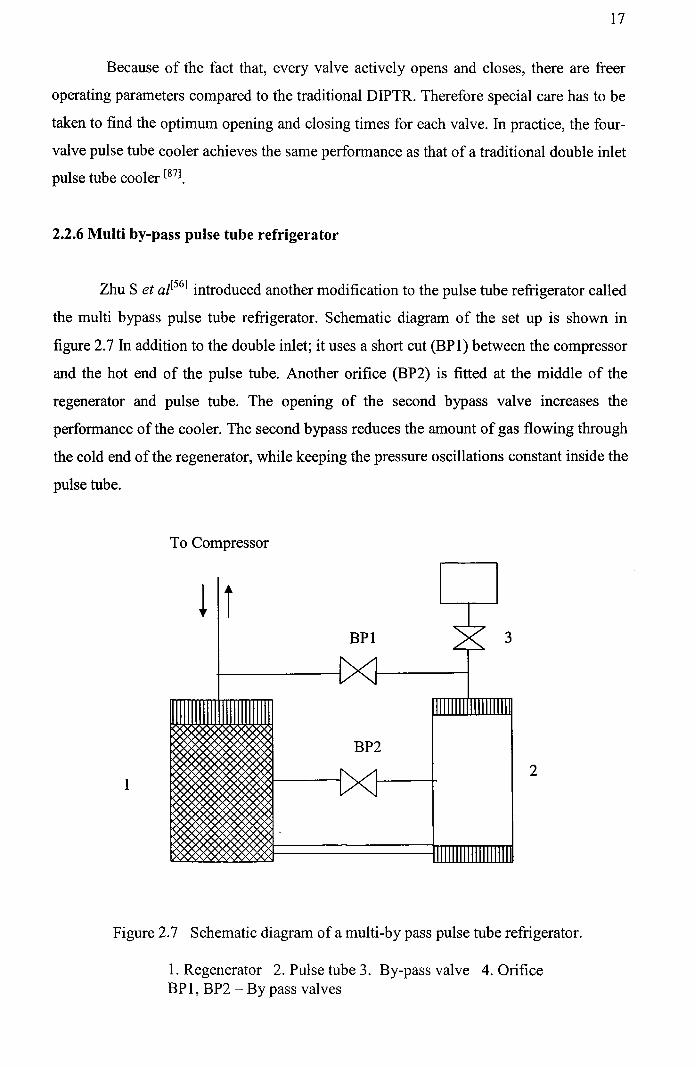
2.2.6 Multi by-pass pulse tube refrigerator
Zhu S et al[56] introduced another modification to the pulse tube refrigerator called
the multi bypass pulse tube refrigerator. Schematic diagram of the set up is shown in
figure 2.7 In addition to the double inlet; it uses a short cut (BP 1) between the compressor
and the hot end of the pulse tube. Another orifice (BP2) is fitted at the middle of the
regenerator and pulse tube. The opening of the second bypass valve increases the
performance of the cooler. The second bypass reduces the amount of gas flowing through
the cold end of the regenerator, while keeping the pressure oscillations constant inside the
pulse tube.
To Compressor
BPI
12
Figure 2.7 Schematic diagram of a multi-by pass pulse tube refrigerator.
1. Regenerator 2. Pulse tube 3. By-pass valve 4. OrificeBP 1, BP2 - By pass valves

18
2.2.7 Active buffer pulse tube refrigerator
In a pulse tube working with a Gifford-McMahon type compressor, at the moment
the high-pressure valve opens, the pulse tube and regenerator are at low pressure. So, a
large pressure difference exists over the valve. This is true for the low pressure also; at
the moment the valve opens the pulse tube and regenerator are at high pressure. In both
cases it leads to a loss in performance due to high-pressure differential across the valves.
The only way to decrease the loss without decreasing the cooling power is, to decrease
the pressure difference over the valve when it opens. For this purpose Shaoweri Zhu et at
[73] introduced a new modification called the active buffer pulse tube refrigerator.
The active buffer pulse tube has no orifice at the hot end of the pulse tube, but at
least two reservoir volumes are connected to the pulse tube with a switching valve as
shown in figure 2.8. Key point in this cycle is that, when the high-pressure valve opens
Rl R2
Figure 2.8 Schematic diagram of an active buffer pulse tube refrigerator with two
reservOIrs.
Rl, R2 - switching valves, HP-high pressure valve, LP-low pressure valve.

19
there is almost no pressure difference over the valve. Same holds for the low-pressure
valve also. But the large pressure difference exists over the valves to the buffer volumes.
So, active buffer pulse tube cooler has better performance than the Gifford Mc-Mahon
type orifice pulse tube cooler. But the increased complexity and size is a disadvantage.
2.2.8. Inertance type pulse tube refrigerator
In a PTR, the cooling power is a function of the phase difference between the
mass flow rate at the cold end heat exchanger side and the pressure. In a BPTR, the heat
exchange between the gas and the tube wall is responsible for the necessary phase shift.
Without heat exchange, the pressure and mass flow are 90 degrees out of phase and no
cooling power is created. In an OPTR, the orifice between the hot end heat exchanger and
reservoir creates the required phase shift.
In general, the mass flow at the cold heat exchanger has an in-phase and an out
of-phase component compared to the pressure oscillations. Only the in-phase component
is contributing to the cooling power. So if the out-of-phase component can be suppressed,
the performance will increase due to reduction in regenerator losses. One method to
create the necessary phase shift to suppress the out of phase component is by connecting a
long capillary tube or inertance tube [70] connecting the hot end of pulse tube with
reservoir volume. As shown in figure2.9 the tube replaces the orifice in the OPTR. A
typical inertance tube is several meters long. Due to the inertance and the resistance of the
tube, a phase shift between pressure and mass flow is created. If length and diameter of
the tube, cycle frequency and volume of the pulse tube are properly selected, the cooling
power can be improved by the right phase shift at the cold end. Pulse tube refrigerators
are also classified according to their geometry or shape or how the components are
placed. These are linear type, U type and coaxial type pulse tube refrigerators as
described below.

20
Inertance tube
Figure 2.9 Schematic diagram of a pulse tube refrigerator with inertance tube.
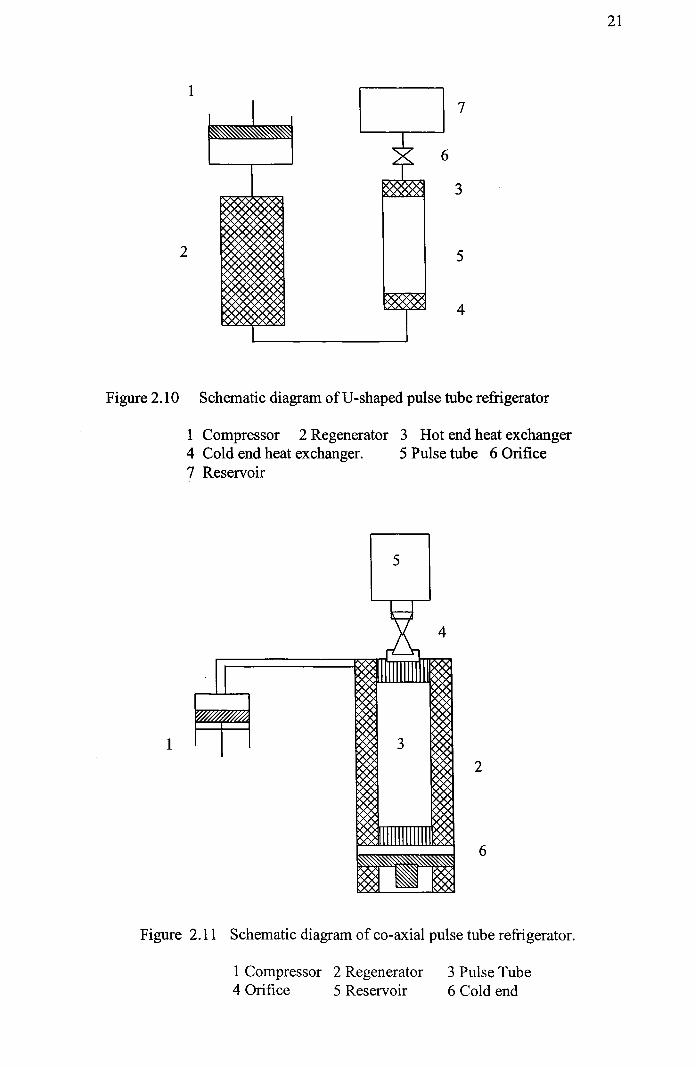
2.2.9 Linear type and U shaped pulse tube refrigerator
If the regenerator and the tube are in line, as shown in figure 2.2, it is called a
linear pulse tube refrigerator. The main disadvantage of the linear type PTR is that, the
cold region is in the middle of the cooler. For many applications it is preferable that the
cooling is produced at the end of the cooler. Bending the PTR at the cold end of the
regenerator and the tube makes U shaped PTR as shown in figure 2.10. Both ends can be
mounted on the flange of the vacuum chamber at room temperature. This is the most
common shape of PTRs. For some applications it is preferable to have a cylindrical
geometry. In that case the PTR can be constructed in a coaxial way [24]; so that, the
regenerator becomes a ring shaped space surrounding the pulse tube. The schematic
representation of coaxial refrigerator is shown in figure 2.11.
1
21
7
2
6
3
5
4
Figure 2.10 Schematic diagram ofU-shaped pulse tube refrigerator
1 Compressor 2 Regenerator 3 Hot end heat exchanger4 Cold end heat exchanger. 5 Pulse tube 6 Orifice7 Reservoir
5
1 3
2
6
Figure 2.11 Schematic diagram of co-axial pulse tube refrigerator.
1 Compressor 2 Regenerator4 Orifice 5 Reservoir
3 Pulse Tube6 Cold end

22
One disadvantage of this construction is that, there is thennal contact between the
tube and the regenerator. Generally, the temperatures of the components differ, which
leads to heat exchange, which results in degradation of perfonnance. The coaxial
configuration of pulse tube refrigerator makes the pulse tube refrigerator compact, small
and light.
2.3. Existing theories
In the course of the development of PTR, continuous efforts have been devoted to
the understanding of its refrigeration mechanism. Varieties of theories have so far been
proposed, and are explained below.
2.3.1 Surface heat pumping theory
In ,the early stages of development, W.E Gifford and Longsworth[3] suggested
that, only the gas element travelling between the cold end and wann end can be
responsible for the cooling effect. This leads to a lower limit of pressure ratio below,
which the pulse tube could not work. But later studies showed that, pulse tube could
provide refrigeration perfonnance at very low-pressure ratios. This implies that heat is
pumped from the cold end to wann end step by step, provided that there exists proper
thennal interactions between the gas element and the tube wall. They described this effect
as the surface heat pumping effect.
Surface heat pumping is caused by,
~ an unusual interaction between fluid displacement along a surface
~ energy change in the fluid and
~ heat exchange with the surface as a result ofa periodic change ofpressure of gas.
23
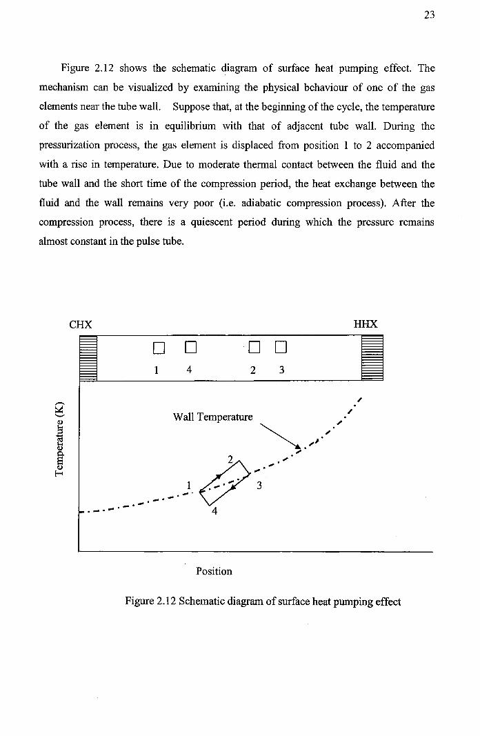
Figure 2.12 shows the schematic diagram of surface heat pumping effect. The
mechanism can be visualized by examining the physical behaviour of one of the gas
elements near the tube wall. Suppose that, at the beginning of the cycle, the temperature
of the gas element is in equilibrium with that of adjacent tube wall. During the
pressurization process, the gas element is displaced from position I to 2 accompanied
with a rise in temperature. Due to moderate thermal contact between the fluid and the
tube wall and the short time of the compression period, the heat exchange between the
fluid and the wall remains very poor (i.e. adiabatic compression process). After the
compression process, there is a quiescent period during which the pressure remains
almost constant in the pulse tube.
CHX
o1
o4
o 02 3
HHX
Wall Temperature
Position
Figure 2.12 Schematic diagram of surface heat pumping effect

24
The gas element with its temperature higher than that of adjacent tube wall
transfers heat to the tube wall and moves from position 2 to 3 as a result of the slight
contraction of the element, due to cooling by the tube wall. Its temperature approaches
that of tube wall. During the expansion process, the gas element is displaced from
position 3 to 4, with its temperature T4 less than initial temperature T(. During the
quiescent period that follows the expansion, the gas element absorbs heat from the
adjacent tube wall and moves from position 4 to I due to slight expansion of the gas
element being heated by the tube wall. At position I, the temperature of the gas element is
equal to its initial temperature thus completing one cycle. It can be seen that during this
cycle, the gas element takes heat from the tube wall at position 4 and gives back to the
tube wall between position, 2 and 3. The net effect of the cycle has been the removal of
the heat from one part of the tube wall and depositing of that heat in the wall at another
part which is closer to the closed end. This effect occurs through out the length of the tube
and produces a heat pumping effect from the open end to the closed end. This provides a
certain refrigeration capacity at the cold end, whilst the hot end is maintained at room
temperature by dissipating heat to the environment.
Surface heat pumping theory was originally developed, to explain the refrigeration
mechanism of the BPTR. After the development of orifice pulse tube refrigerator,
Mastubara[23] and Richardson [25] considered the gas reservoir and orifice as means for
enhancing the surface heat pumping mechanism by allowing more gas to come in contact
with the hot end heat exchanger. But as described in the following sections, some others
approached the problem in quite a different way.
2.3.2 Enthalpy flow theory
The surface heat pumping theory explains the working of pulse tube refrigerators by
examining the physical behavior of one of the gas elements. Soon after the development
of OPTR Radebaugh et at [16, 18,27] proposed the enthalpy flow theory based on the time
averaged effect of the pulse tube as a control volume.

25
Consider a cross section of the pulse tube. For an ideal gas, the enthalpy flow rate
through this section,
H=mh=mc Tp (2.1)
The time average of the enthalpy flow rate over one cycle ofperiod T is given by
Where, m=p Apt U
For an ideal gas p =~ , where P is pressure.RT
The time average enthalpy flow rate can be written as
r
<If >= (CpAp';;;T )fUPdt
o
If the cyclic pressure and velocity variations are assumed sinusoidal; i.e.
P = Pay +PA sin(OJt)
U = uA sin(OJt-¢)
where, OJ = 2 Jrf
(2.2)
(2.3)
(2.4)
(2.5)
(2.6)
. .' 1(CPApt IJEquatIon (2.4) can be wntten as < H >=2" IR U A PA cos rjJ
It can be seen from this equation that,
when, ¢=O; <H>=<H>max
when, ¢ = (~) ; < H >= 0
26
(2.7)
(2.8 )
(2.9)
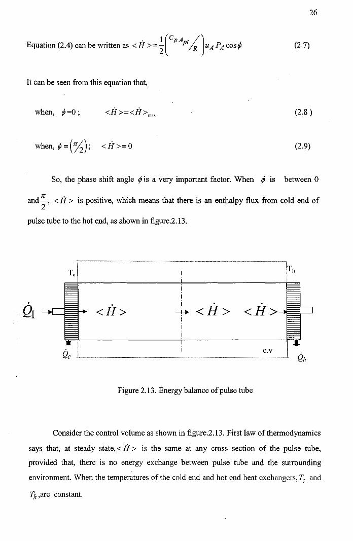
So, the phase shift angle ¢ is a very important factor. When rjJ is between 0
and 7r, < H > is positive, which means that there is an enthalpy flux from cold end of2 .
pulse tube to the hot end, as shown in figure.2.13.
.<H>
.Q
T,r···············_···················_·················..........................................•...........····························ITb
III •
---*<H>III
Q. C.vc .
Figure 2.13. Energy balance ofpulse tube
Consider the control volume as shown in figure.2.13. First law of thermodynamics
says that, at steady state, < H> is the same at any cross section of the pulse tube,
provided that, there is no energy exchange between pulse tube and the surrounding
environment. When the temperatures of the cold end and hot end heat exchangers, Tc and
'FJl ,are constant.

27
The first law of thermodynamics gives
(2.10)
(2.11)
where, Qf is the net refrigeration power, QI is the total loss of cooling, Qh is the heat
rejected at the hot end heat exchanger. From equation (2.10), it can be seen that the
refrigeration capacity at the cold end comes from the enthalpy flux < if > in the pulse
tube, and is therefore dependent on the phase shift angle tjJ •
According to Radebaugh et al [14], the proper phase shift angle tjJ in the basic
pulse tube refrigerator is brought about by intermediate thermal contact between gas and
the tube wall. In the orifice pulse tube, a much better phase relationship (smallertjJ) is
achieved mainly by the orifice and gas reservoir, which is much more effective in shifting
the phase angle between pressure and velocity. This explains the superiority of the orifice
pulse tube refrigerator with respect to the basic pulse tube refrigerator. But they
considered the heat exchange between gas and pulse tube wall detrimental to the
refrigeration performance of the orifice pulse tube refrigerator.
Based on the enthalpy flow theory, PJ.Storch et al [18] developed an analytical
model of the orifice pulse tube refrigerator using the phasor analysis method. With the
assumption of sinusoidal behaviors and small fluctuation amplitudes for the dynamic
variables, the energy and mass conservation equation can be greatly simplified. The
model is consistent with the first law of thermodynamics and is successful in predicting
the dependence of performance of the important parameters. But theoretical values for the
refrigeration power are 3 to 5 times greater than the experimental measurements. Later
M.J.A Baks et al [30] published a modification of this model, by taking in to account the
influence of pulse tube wall. Recently M.David et al [52] has developed an analytical
model similar to that of, PJ.Storch et ai, except that it is applicable to any pressure wave

28
fonns and that the gross refrigeration power IS correlated with less independent
parameters and obtained more accurate results.
2.3.3 Thermo acoustic theory
Although the enthalpy theory seems to be of the nature of classic
thennodynamics, it probably originated from the thenno acoustic theory, which had been
developing for a long time. When there is a sufficiently large axial temperature gradient
along a tube, the fluid in the tube becomes unstable and begins to oscillate spontaneously.
The thennally induced spontaneous oscillations, known as 'Taconis oscillations', in
cryogenics have been studied for over two centuries. In 1970's, a theoretical break
through was achieved by Rott[9]. He discussed the stability of standing wave using
linearised equations of fluid dynamics. Merkli and Thomann [8] studied another type of
thenno acoustic effect, which is just the reverse of the effect of thermally induced
spontaneous oscillations. When a piston drives the fluid in a tube with one end closed, to
oscillate at the resonant frequency, axial temperature gradient will be established on the
tube wall. If the Prandtl number of the gas is less than one, time average cooling nears the
velocity node (in the middle of the tube) and time average heating near the pressure nodes
(at the two ends of the tube) can be observed. This phenomenon is theoretically explained
in tenns of second order heat flux since, only the tenns of the second and high orders in
the energy equation contribute to the time average cooling and heating. Merkli and
Thomann, used this idea to develop resonance tube as a heat pump [8]. Wheatly et al [10, 12,
and 13] incorporated these theories in their work and successfully developed a thenno
acoustic refrigerator. The working principle of it is similar to that of the basic pulse tube
refrigerator. It operates at the resonance frequency (about a few hundred Hertz) of a tube
filled with closely spaced thin cloth-epoxy plates [8,10,12, and 13]. The amplitude of pressure
oscillation in the tube is very small (much less than 1 bar). Since, its configuration and
operating conditions are greatly different from those of the previously said three types of
pulse tube refrigerators; the thenno acoustic refrigerator is not within the range of study
of this work.
All these authors mainly dealt with standing waves. However in the pulse tube
refrigerator, as well as in any other regenerative refrigerators or heat engines, both

29
standing and traveling waves may be present. J.H. Xiao [40,42] applied the thermo acoustic
theory to the regenerative machines.
Although, for the moment, the thermo acoustic theory may not yet be adequate for
practical systems, it introduces some new concepts, which are helpful to the
understanding of regenerative machines including the pulse tube refrigerator[22].
Conventionally, the regenerator is thought to be a heat exchange device, which passively
isolates the cold end of the pulse tube from room temperature. In a thermo acoustic point
of view, while the time average enthalpy flow through a perfect regenerator is zero, there
are time average work flow from the hot end to the cold end of the regenerator and
equivalent time average heat flow in the opposite direction. The pressure wave generator
is regarded as a device to generate time average workflow toward the pulse tube. The
latter absorbs a small part of the workflow and conduct the rest to the hot end where
workflow is dissipated to the surroundings via the orifice and gas reservoir. This is
consistent with the enthalpy flow theory, which says that there is a time average enthalpy
flow in the pulse tube. More workflow is dissipated by the pulse tube, orifice and gas
reservoir, and more heat is transported from the cold end to the hot end of the regenerator.
This is the thermo acoustic explanation of the fact that the orifice pulse tube refrigerators
have better performance than the basic pulse tube refrigerator.
2.3.4 Thermodynamic non -symmetry effect
In 1996 J Liang et at [63] proposed a model based on the thermodynamic non
sYmmetry effect of the gas elements working at the cold end of the pulse tube refrigerator.
Major difference between previous and this model is that, previous model has taken
complete pulse tube as one element; but this model has divided the gas element entering
the pulse tube through the cold end into 'n' parts, whose thermodynamic parameters are
nearly same. In the model, the pressure variations in the system are assumed to be known
and the mass flow rate at the cold end is calculated.
The first half of the cycle starting from the gas intake at the cold end of the pulse tube
is evenly divided into 'n' intervals of time. In the second half of the cycle gas element n
leaves the cold end ofpulse tube at time tn+l, and element (n-l) leaves at time tn+2 etc. In a

30
similar way this can be concluded that element tn+l-i leaves at time tj and one cycle will
complete in time t 2n.
Refrigeration effect produced by this lh (l:Sj :Sn) element is given by
(2.12)
Total refrigeration power will be
(2.13)
2.3.5 Zhu's energy balance model
In 1990, Zhu et al [33] used a different approach to understand the mechanism of PTRs.
He assumed that, gas inside the pulse tube does not mix and process involving the gas in
the pulse tube, is ideal adiabatic process. According to the above assumptions, the gas in
the pulse tube can be divided into three parts as shown in figure 2.14.
4
III
3
II
2
I
Cold end HX HotendHX
Figure 2.14 Schematic diagram of gas distribution in pulse tube

31
The assumptions are,
~ First part is at the hot end of the pulse tube refrigerator and flows into the pulse
tube from hot end heat exchanger and flows out of the pulse tube after a period of
time.
~ Second part is in the middle section and never flows out of the pulse tube.
~ Third part is at the cold end of the pulse tube and flows into the pulse tube from
the regenerator.
Energy equation for each part is as follows
(2.14)
(2.15)
(2.16)
Zhu solved this model and concluded that:
1. Mass flow rate at section '4' should be in phase with pressure for maximum
refrigeration power.
2. In the case ofOPTR, some part ofmass flow rate at section '4' is not useful for
producing refrigeration power. This part ofmass flow rate is known as useless
mass flow rate. The mass flow rate through regenerator is high and refrigeration
effect per unit mass flow rate is low.
3. This useless mass flow rate Increases with the reduction of refrigeration
temperature.

32
2.3.6 Nodal analysis
Mastubara and Zhu [92) simulated inertance pulse tube refrigerator with the help of
nodal analysis. The energy equation, continuity equation, momentum equation of gas and
energy equation of solid were included in this model. This model can also be used for
BPTR, OPTR and DIPTR by appropriate change in boundary conditions. Flow is
considered to be one dimensional compressible fluid flow and the governing equations
are,
Continuity equation:
a a-(pA)+-(puA)=Oat ax
Momentum Equation:
a a 2) ap f 2 u-(pAu)+-(pAu +A-+A-pu -=0at ax ax 2De luI
Energy Equation:
Energy equation for Matrix:
(2.17)
(2.18)
(2.19)
(2.20)
All these differential equations were simplified to algebraic equations and applied to
various part of the PTR with appropriate boundary conditions.

33
Enthalpy flow at any point is given by
(2.21)
Hence refrigeration effect is given by
(2.22)
Here Hpt is the enthalpy flow through pulse tube and Hrg is enthalpy flow through
regenerator.
2.3.7 Isothermal model
Zhu and Chen [55] presented the isothermal model and analyzed the pulse tube
cryocooler. They treated the pulse tube model as split Stirling model. This model is
favourable because of its simplicity over nodal analysis. The main assumption was that,
the gas in the middle portion is adiabatic while that in other portion is isothermal. Atrey
and Narayan Khedkar[83] further developed the second order isothermal model for an
OPTR. The predictions from the model are compared with the actual experimentation and
the results were found to be in good agreement. Various losses were computed and
accounted for as:
1. Loss due to Regenerator ineffectiveness.
2. Shuttle heat conduction loss
3. Temeperature swing loss
2.4 Survey of literature
Gifford first conceived the idea of pulse tube refrigeration as a new method of
achieving cryogenic temperatures in 1961. Although, the development of pulse tube
models for research purposes was started in 1962, first paper [I] giving a brief account of
progress made was published in 1964. The phenomenon was described as "pressurization

34
and depressurization of any closed volume from a point on its periphery set up
temperature gradients in the volume. Obviously the temperature gradient thus obtained
depends upon the geometry of closed volume and the conditions of operations.
Pressurization and depressurization of a constant volume system will lead to transfer of
heat within the volume and outside the volume. The transfer of heat may be used in
combination with heat exchangers and regenerators to build a refrigerator.
In the second paper published in 1965, Gifford and Longsworth [2] reported to
have a pulse tube refrigerator operating well below the critical pressure ratio. They
reported about a 2-stage unit achieving a temperature of 124K with He and 152K with air.
In 1966, W.E.Gifford and R.C.Longsworth[3] described a heat pumping process
which has come to be known as surface heat pumping (SHP), which may be set up on any
surface of a closed chamber where pressure is varied by the delivery of gas from one
point. This is due to an unusual interaction between fluid displacement along a surface,
energy change in the fluid and heat exchange with the surface as a result of periodic
change of pressure of the gas. Significant amounts of heat can be pumped against large
temperature differences with an efficiency approaching that of Camot cycle. This
provided a much better qualitative explanation of the operation of pulse tube refrigeration
operation. They developed a relation for the cold end temperature with zero heat-pumping
rate in terms oflength ratio, hot end temperature and ratio of specific heats of gas with the
help of SHP mechanism.
In the same year, R.C.Longsworth [4] conducted an experimental investigation of
pulse tube refrigerator heat pumping rates. He developed an empirical relation that gives
the heat-pumping rate of a pulse tube to correlate the experimental results with fair degree
of accuracy. He characterized the heat transfer in the pulse tube by the Fourier number
and concluded that, tubes with the same length dimensions but different diameters and
operating at the same conditions except having speeds such that nD2 (where, n=pulse rate,
D = tube diameter) is the same, pump the same amount of heat.
In 1967 W.E.Gifford [5] compared the working of a reversible pulse tube with that
of a valved pulse tube and showed that a pulse tube with valves loses greatly in efficiency
due to irreversible isenthalpic expansion through the valves. The basic method of

35
inefficiency can be eliminated by replacing the valves and compressor system with a
piston and chamber, which can be varied in size from zero to maximum one by the
motion of the piston.
Previously published papers[I.2] based on classical adiabatic or polytropic
compression and expansion processes have neglected convective heat transfer between
the gas and pulse tube wall. Hence the experimental data have not agreed too well with
the theory. In 1962 J.W. Colangelo[6] accounted the heat transfer occurring during the gas
motion and heat conduction through the gas by the heat transfer coefficient 'h'.
In 1972 Narayankhedkar and Mane[7] reported a theoretical analyses and
experimental investigation of the pulse tube refrigerator. A concept of steps has been
introduced for the derivation of cold end temperature with zero heat-pumping rates. This
relation indicated that cold end temperature with zero heat-pumping rates depends not
only on the length ratio, hot end temperature and ratio of specific heat of gas used, but
also on the pressure ratio employed. An empirical relation for heat pumping rate has also
been suggested. Experimental investigation has indicated that, there exists an optimum
hot end length and that the optimum speed decreases with increase in the total length of
pulse tube.
John Wheatly et at [10] described certain thermo acoustic effects, which form the
basis for a heat engine that is intrinsically irreversible, in the sense that it requires thermal
lags for its operation. The qualities of the intrinsically irreversible thermo acoustic
engines have been generalized to apply to a wide variety of heat engines. The results of
analysis suggests that the efficiency of such engines may be determined primarily by
geometry or configuration, rather than by temperature.
Mikulin et at [II] installed an orifice at the top of the pulse tube to allow some gas
to pass into a large reservoir volume. This type of configuration is called orifice pulse
tube refrigerator. In the original work, they placed the orifice just below the isothermal
section. Using air as working fluid, they achieved a low temperature of nearly 100 K and
predicted that with helium as working fluid this type of pulse tube refrigerator could reach
temperature levels below 60 K.

36
In 1986 Radebaugh et al [14] presented a new version of the above model, in
which an orifice above the isothermal section is placed and produced a low temperature
of 60K using helium gas. The tube was 12.7mm in diameter and 240mm long, operated at
a frequency of 9Hz with a valve-less compressor. He also performed the measurements of
the refrigeration capacity per uniform mass flow as well as the thermodynamic efficiency
of the cooling process, which occurs within these pulse tubes. The effect of tube diameter,
tube length, orifice setting and frequency were investigated. In some cases, when
compressor and regenerator losses were neglected efficiencies as high as 90% of Carnot
efficiency were measured.
In 1986, Richardson [15] presented both theoretical and experimental results, which
helped to explain the nature of the device. The principle of temperature stratification was
explained and suggested that, it results in the establishment of temperature gradient along
the pulse tube, which is maintained by the surface heat pumping mechanism. The
research has enabled a more comprehensive explanation of heat pumping mechanism
and the possible relevance of surface heat pumping to the non-ideal behavior in certain
types of cryocooler.
Radebaugh [16] compared the three types of pulse tubes such as Basic, Orifice, and
Resonant with each other and with common refrigerator such as Joule Thomson and
Stirling refrigerators. Overall efficiency as well as sources of loss, such as conduction and
regenerator ineffectiveness is discussed and the advantages of various phase shifting
techniques to increase refrigeration capacity are compared. Since it can reach a
temperatures of 60K in single stage, it was concluded that orifice pulse tube offer a viable
alternative to Stirling and Joule Thomson refrigerators for situations where, high
reliability is needed. In their experiments, they achieved a low temperature of 60K using a
single stage pulse tube similar to that of Mikulin [11].
In 1987 Ray Radebaugh [17] compared various pulse tube refrigerators and Stirling
refrigerators using a newly developed enthalpy model. He showed that the expansion
piston of the Stirling refrigerator, which is used to cause a phase, shift between the mass
flow rate and pressure is replaced with either irreversible heat transfer or irreversible
expansion through an orifice to bring about the necessary phase shift.

37
In 1988 Storch et al [18] developed an analytical model, describing the behavior of
orifice pulse tube refrigerator. Phasor analysis is used to represent the temperature,
pressure and mass flow rate in vector form. The analytical predictions are validated with
experimental results. The magnitude of the refrigeration power predicted by the above
model is 3-5 times higher than the experiment, because of simplifying assumptions used
in the model.
Zhou et at in 1988 [19] conducted an experimental investigation to compare the
performance of coiled pulse tubes with those of straight ones having similar cross
section, length and operating conditions. The performance degradation of coiled pulse
tube had also been reported, when ratio of the axial radius to the radius of cross section is
reduced. The influence of flow resistance on refrigeration performance had been
discussed.
In 1988 Richardson [20] explained the influence of viscosity on the surface heat
pumping mechanism. It had been shown that, the miniaturization of the pulse tube is quite
feasible, provided the effect ofviscosity is appreciated.
In 1988 Radebaugh et al [21] conducted experiments to determine the minimum
temperature and maximum refrigeration power available with an orifice pulse tube
refrigerator, driven by a compressor with a fixed swept volume of 25 cm3. With fixed
compressor swept volume, the regenerator mesh size pulse tube volume and frequency
were optimized.
Mastubara et at [23] described the alternative methods to the orifice pulse tube
refrigerator for the purpose of improving the refrigeration power per unit mass flow rate.
They introduced a moving plug operating at room temperature, instead of the orifice, in
order to produce the optimum phase shift between pressure and volume change. The
moving plug used instead of orifice, is an active device, therefore it can change the phase
and speed of movement independently. A minimum temperature of 73 K at 10Hz was
obtained. They also suggested an analytical model for pulse tubes with moving plug and
orifice. They also concluded that, in case of refrigeration temperature above 80K, the
moving plug is superior to orifice, since expansion work done by the moving plug is
recovered.
38
The need for high reliability and low cost cryocooler led to the development of
thermally actuated pulse tube refrigerator, by Kaneko et at [24] in 1988. Normally, a
mechanical compressor is used to drive the pulse tubes. But Mastubara studied a
thermally activated pulse tube refrigerator, where a hot displacer is used to move gas
between a heated volume and a room temperature volume to generate pressure
oscillations like Vuillimier refrigerator-The thermally actuated pulse tube refrigerator has
been operated at the temperature of about 200K.
In 1989, Richardson [25] optimized a valved pulse tube, which involves the two
variables of throttle setting and buffer vessel volume. The optimum ratio of pulse tube
diameter to throttle diameter is typically in the range of 10- 20. The optimum pulse rate
was found to be 7 Hz, which is considerably higher than the optimum of approximately
2.5 Hz for simple device.
In 1989 Wu et at [26] performed numerical analyses for an orifice pulse tube
.refrigerator with a valve-less compressor and described the process occurring in pulse
tube.
In 1990, Radebaugh[27] studied about the overall system performance with
different sizes of compressors and did analytical and numerical modeling of pulse tube
refrigerator. The analytical modelling is useful for understanding the physics of the
process and for determining the important parameters, which affect refrigeration power.
But numerical modeling gives much more accurate results as the assumptions are
removed and solving the differential equations for conservation of mass, momentum and
energy. The analytical model predicted the proper dependence of refrigeration power on
various parameters although the effect ofbuffer gas in the middle of the pulse tube should
be studied further, since, it could explain the difference between the theoretical and
experimental refrigeration powers.
In1990, Wayne Rawlins [28] discussed the design and construction of an apparatus
to measure the ineffectiveness of regenerators used for pulse tube refrigerators. Because
of fairly large mass flow rates, which occur in pulse tube refrigerators, the regenerator
ineffectiveness must be made quite small. The apparatus described allows for the

39
measurement of regenerator heat loss under actual operating conditions in pulse tube
refrigerators.
In 1990 Wang et aP9] introduced a practical coaxial orifice pulse tube
refrigerator, to make the pulse tube small and compact. With this refrigerator a minimum
temperature of 62K and 2.5W of cooling power at 17K were achieved.
In 1990, Baks et al [30] performed an experimental verification of an analytical
model for pulse tube refrigeration. The cooling power of a pulse tube refrigerator had
been expressed in terms of regenerator loss and average enthalpy flow through the pulse
tube. Neglecting in a first approximation, the heat exchange with the wall of pulse tube,
enthalpy flow through the pulse tube is dependent on the amplitudes of the pressure
fluctuations in the pulse tube and volume flow through orifice. The interpretation of the
experiment had been simplified by elimination of the influence of regenerator loss by
keeping the cold end heat exchanger at ambient temperature.
Marc David [31] conducted studies to achieve the efficiency of a G-M cryocooler
with a pulse tube refrigerator. For this, they developed a hybrid system that permits to
obtain very high efficiency. The hybrid pulse tube united the pulse tube reliability and the
G-M cryocooler efficiency. With a standard compressor used for a G-M machine, they
obtained a 57K temperature with a single stage and net refrigerator power of 12W at
12K.
Zhu et al [32] in 1990, has given the results of experiments conducted on an
improved version of PTR named double inlet pulse tube refrigerator, in which both ends
of the pulse tube were connected with a pressure wave generator. A no load temperature
of 42K has been achieved by single stage double inlet pulse tube refrigerator which was
13 K below that obtained by conventional orifice pulse tube refrigerator with same size
and operating conditions.
In 1990 at X'ian Jiaotang University China, Zhu et al [33] achieved a new
construction solution to increase the orifice pulse tube refrigerator efficiency called
double inlet pulse tube refrigerator (DIPTR). They have documented how the pulse tube
refrigerator works and why mass flow rate through the regenerator is so large, why the

40
refrigeration power per unit mass flow rate through the regenerator so low, how to reduce
the mass flow rate through the regenerator and how to increase the refrigeration power
per unit mass flow rate through the regenerator. Numerical analysis and experimental
results confirm that the double inlet pulse tube has improved performance over the orifice
pulse tube refrigerator. He concluded the following points:
~ The refrigeration mechanism of the pulse tube is similar to that of the Stirling
cryocooler, the difference being that a gas column has replaced the displacer.
~ The main disadvantage of the orifice pulse tube refrigerator is that, a large
volume of gas with no refrigeration effect flows through the regenerator into
the pulse tube because of pressure fluctuation, which makes the mass flow
through the regenerator low.
The double inlet pulse tube refrigerator can overcome the above disadvantages of
the orifice pulse tube refrigerator. In the double inlet orifice pulse tube refrigerator, the
gas flowing into the pulse tube from the cold end can do maximum work, the mass flow
through the regenerator into the pulse tube has been reduced and the refrigeration power
per unit mass flow rate through the regenerator has been significantly increased.
Harpole G M & Chan C.K [34] conducted a sensitivity study and demonstrated the
strong dependence of system performance on orifice valve setting. There is an optimum
valve coefficient that gives peak performance. Increasing the swept volume increases
both the cold end cooling and the compressor work nearly proportionally so that the
efficiency variation is small. The study showed that, the performance can be significantly
improved if the regenerator pressure losses are reduced.
In 1990 Huang 8.J. et at [35] performed a system design analysis to predict the
performance of pulse tube refrigerator. It was found that the performance of a pulse tube
cryocooler depends on six operating parameters. They are charging pressure, discharge
pressure, charging gas temperature, heat sink temperature, and cold end temperature and
pulse rate. The analytical results obtained in the study indicated that the convective heat
transfer between the gas and the tube wall or regenerator matrix, during flow periods may
be a controlling mechanism in the performance of basic pulse tube refrigerators.

41
In 1990, Wu Peiyi et al [36] analyzed the working of a valve less stepped piston
compressor. They analyzed its working process, determined the suitable size of the piston
area ratio and showed the influence of the piston area ratio on the refrigerator. Analysis
shows that this type of refrigerator has the potential to get lower temperature but the input
power should be increased. Numerical analyses shows that the net refrigeration power
will be increased or the no load temperature will be decreased by this type of refrigerator.
Wayne Rawlins, et al [37] constructed an apparatus to measure the performance of
regenerators in pulse tube operating at pressure oscillations between frequencies in the
range of 5 to 30Hz. The apparatus measures the ineffectiveness of a regenerator when
used in a PTR. He also made real time measurements of the important operating
parameters in an orifice pulse tube refrigerator .The measurements allowed evaluation of
the dynamic pressure drop and friction factor in the regenerator.
In 1991, Kasuva et al [38] studied the role of heat exchange between the gases in
the pulse tube and the tube wall in a pulse tube refrigerator. For this, experiments were
conducted to study the workflow going through the pulse tube without heat exchange by
mounting a piston on the hot end of the pulse tube. Refrigeration power is found to
increase as the work flow reaching the hot end piston increases and the heat released into
a room temperature environment decreases as the work flow increases. This suggests that
the workflow becomes more important as the refrigeration power increases.
In 1992, Mineo Tanaka [39] formed a lissajous figure by converting the pressure
and temperature oscillations in the pulse tube. Using this method, the phase difference
between the pressure and displacement of the gas, the amplitude of the gas motion can be
estimated. These are useful to understand the performance of the refrigerator.
In 1992, Bin Zhou, Peiyi Wu, et al [41] presented the test results, to reveal, the
effects of some important parameters, such as bypass valve and orifice opening, operating
frequency and mean pressure on the amplitude shift and phase shift of three dynamic
pressures at the hot end of the regenerator, pulse tube and reservoir.
In 1992, Xiao J.H [42] gave a brief introduction to the basics of thermo acoustics
approach for regenerative cryocooler analyses. He developed the linear thermo acoustic

42
approach for regenerative cryocoolers, which reveals that the working mechanism of
regenerative cryocoolers relies on thermo acoustics effects. The thermo acoustic approach
can be used to predict the flow dynamics and thermal performance of cryocoolers. The
case study for an orifice pulse tube refrigerator showed that, the regenerator is responsible
for the heat pumping effect in pulse tube refrigerator, which consumes acoustic energy
and transform it into heat energy to pump heat from its cold end to hot end. The pulse
tube, the orifice and reservoir act as a gaseous expansion piston engine that absorbs the
acoustic work flux coming from the regenerators.
In 1992, Marc David et at [43] described a practical method to calculate the
theoretical gross refrigeration power of an ideal orifice or double inlet pulse tube
refrigerator. They conducted experiments to measure the actual value of refrigeration
power and independently the refrigeration loss. For this purpose they developed an
analytical model of an ideal orifice pulse tube refrigerator. They deduced the performance
of the ideal orifice pulse tube refrigerator or double inlet pulse tube refrigerator by only
measuring the gas pressure as function oftime in the pulse tube and reservoir.
In 1992, Ravex et atl44] built a test bench for pulse tube refrigerator
characterization. They measured ultimate temperature and cooling as a function of
pressure wave amplitude and frequency for various geometries. Results obtained with
their model were in good agreement in general shape of the temperature variation with
frequency.
Lee J.M. et at [45] conducted a study to examine the energy transfer mechanism
within the pulse tube refrigerator. Their main aim was to develop a thorough and detailed
understanding of enthalpy transport mechanism within the open tube of pulse tube
refrigerator. The Navier Stokes equation of motion is addressed for a slowly oscillating
viscous fluid and solutions are compared to direct visual flow observations. They
presented the flow pattern for the oscillating gas flow within a tube for the basic and
orifice pulse tube configurations and for incompressible flow. A boundary layer
approximation of the incompressible Navier Stokes equation for internal pipe flow of
variable pipe radius is developed. This model is used to explain the observed flow pattern
for both mathematical and physical viewpoints.

43
Kasuya M et at [46] made a study to investigate how the phase angle between
pressure oscillation and gas displacement affects pulse tube refrigeration performance.
The optimum phase angle of piston motion was found to be in the range of 90°-180°. In
orifice pulse tube refrigerator, the available phase angle of gas displacement at the hot
end of the pulse tube (corresponding to piston motion) is restricted between 0 and 90
degrees. Orifice pulse tube refrigerators cannot achieve the optimum phase angle. The
improvement achieved with double inlet pulse tube refrigerators can be explained by their
capacity to reach a phase angle beyond 90°.
An improved numerical modeling technique for predicting the detailed
performance and characteristic of an orifice pulse tube refrigerator has been developed by
Chao Wang et at [47]. They proposed a numerical model, which takes aerodynamic
friction, heat transfer and real material properties in to account. The suggested method is
more powerful for understanding the physical process occurring in the pulse tube
refrigerator and also for predicting some important parameters, which affect the
refrigeration power and efficiency.
Numerical analysis of double inlet pulse tube refrigerator was given by Wang et at
[48]. In which the equation of continuity, momentum and energy are solved. The numerical
predictions reveal the detailed performance and characteristics of double inlet pulse tube
refrigerator.
In 1993, BJ. Huang [49] conducted investigations on the performance
characteristics of pulse tube refrigerators. It was found out that the gas compression and
expansion process inside the pulse tube is similar to a Brayton cycle and lies between
isothermal and adiabatic. From the viewpoint of system dynamics, the performance of a
pulse tube refrigerator can be characterized by the time constant of the regenerator and
the pulse tube wall. They also experimentally showed that the dynamics of basic pulse
tube refrigerators approach that of a first order system.
In 1993, J. Yuyama and M. Kausuya[50] conducted experimental study on the
refrigeration losses in pulse tube refrigerator. They concluded that changing regenerator
length produces almost no effect on minimum refrigeration temperature. But changing the
pulse tube length appreciably affects the minimum refrigeration temperature. It is

44
suggested that the mam heat input is produced by shuttle gas motion along the
temperature gradient in the pulse tube with the present refrigerator dimensions and
operating conditions.
In 1993 Mastubara et aPl] developed a single stage four-valve pulse tube
refrigerator in which the minimum temperature below 30 K and cooling power lOW at
55 K were achieved.
In 1993 David et aP2] analyzed the mechanism of heat flow in the tube and
explained the refrigerating effect as the result of hysteresis of the gas elements entering
and leaving the pulse tube.
Gao and Mastubara[53] conducted an experimental investigation to reach 4 K using
a pulse tube and the best multiple staging configurations for the pulse tube. Experiments
were performed on several types of single stage pulse tube refrigerators coupled with a
GM cryocooler.
C.Wang et at [54] was suggested a modified pulse tube refrigerator without a
reservoir (MOPTR). In this arrangement the crankcase of the compressor is used instead
of the reservoir to bring about the appropriate phase shift between the pressures and flow
velocity in the pulse tube. Experiments have verified that the MOPTR could operate as
successfully as conventional OPTR.
Zhu et at [55] proposed an isothermal model for an orifice pulse tube refrigerator that
IS much simpler than nodal analyses. In this model the pulse tube refrigerator is
considered to be a type of split Stirling refrigerator, and the gas in the pulse tube is
divided into three parts. The gas in the middle portion is assumed to be adiabatic and the
gas in the other two portions is isothermal. The results of the isothermal model are
compared with that of nodal analysis.
J.H. Cai et at [56] introduced the co axial pulse tube refrigerator with multi bypass
to improve the performance. It was experimentally verified that the performance of this
model is better than that of double inlet type. With no cooling load, a lowest temperature
of 33 K was obtained in a single stage pulse tube refrigerator with a multi bypass.

45
In 1994, Boer[57] developed a thennodynamic model of basic pulse tube
refrigerator with various improvements by taking into account the gas motion during the
cooling and heating steps, which result in more accurate temperature profiles.
Wu et at [58] developed a numerical model of orifice pulse tube refrigerator by
using the method of characteristics and made a preliminary comparison with experiments.
Their suggestions are useful and convenient for understanding of the process and design
of the device.
In 1994, Radebaugh et aP9] developed a technique for the instantaneous
measurements of mass flow rate and temperature in an orifice pulse tube refrigerator
during actual operation. They presented the values of enthalpy, entropy and work fluxes
at the cold end of the pulse tube evaluated from the measurements.
Roach et at [60] developed a simple modeling programme for orifice pulse tube
coolers and theoretical analyses of the behavior of a typical pulse tube and made a
comparison with earlier models.
Boer[61] presented thennodynamic analysis of the basic pulse tube refrigerator
with a regenerator and heat exchangers at both ends. The perfonnance of the regenerator
and its adjacent heat exchangers had been investigated using control volume analysis to
detennine enthalpy flows and by control mass analysis to detennine heat flows associated
with individual gas elements.
Roach [62] carried out a theoretical analysis of the behavior of typical pulse tube
regenerator. Assuming simple sinusoidal oscillations, the static and oscillating pressures,
velocities and temperatures were detennined for a model that includes a compressible gas
and imperfect thennal contact between the gas and regenerator matrix. For realistic
material parameters, the analysis reveals that the pressure and velocity oscillations are
largely independent of details of thennal contact between the gas and the solid matrix.
Only the temperature oscillations depend on the contact. Suggestions for optimizing the
design of regenerator are also given.

46
Liang et al [63] idealized the pulse tube refrigeration process by simplifying the
practical conditions without losing the main characteristics of pulse tube refrigeration.
Based on this idealization the thermodynamic non-symmetry effect of the gas element
working at cold end of the pulse tube has been described. The gas elements enter the cold
end of the pulse tube at much lower temperatures. They termed it thermodynamic non
symmetry in the temperature of gas particles entering and leaving the pulse tube during
one cycle. The effect had been conveniently used to explain the refrigeration mechanism
of the basic, orifice and double inlet pulse tubes.
In1996, Liang et al [64] developed the compound pulse tube model based on the
earlier analyses and incorporated the thermal and viscous influence of the pulse tube wall.
Adiabatic calculation ofthe directly coupled compressor has also included in the model.
Liang et al [65] conducted experimental verification on pulse tube refrigerator to
validate their theoretical model. The influence of important parameters such as opening of
orifice and double inlet valve, frequency, average pressure, amplitude of pressure
oscillations in the pulse tube, diameter of the pulse tube or refrigeration performance was
intensively investigated.
Xu et al[66] reported experimental research on a miniature coaxial pulse tube
refrigerator using nylon tube. The coaxial design has been used to decrease heat transfer
between the pulse tube and surrounding regenerator. It had been operated at frequency of
II Hz. with a filling pressure of 1.19Mpa and attained I59.4K as lowest temperature.
Soo J E [67] in 1996 studied the secondary flow in BPTR. The existence of large
scale streaming and the effect of axial temperature gradient on secondary flow within
the basic pulse tube configuration had been shown analytically .The magnitude of the
secondary flow decreases as the temperature difference between the cold and the hot end
heat exchangers of a pulse tube refrigerator increases.
Kittel et al [68] described the qualitative behavior of pulse tube refrigerator on the
basis of simple I-D model. These models have been used to introduce and demonstrate
the useful concept of entropy flow and Gibbs free energy flow. These thermodynamic
flows are useful in identifying loss mechanisms and in evaluating the importance of

47
different losses. An alternative phasor model was developed that emphasizes the
relationship between the different mass flow and pressure components.
Huang et at [69] developed a linear network model for the system analyses of an
orifice pulse tube refrigerator considering the pressure as electric voltage and mass flow
as electric current. The thermal performance calculations can thus be greatly simplified
by solving equivalent circuit of orifice pulse tube refrigerator using a sinusoidal signal
analyses. The linear network analysis provides a powerful tool for the system
performance analyses of an orifice pulse tube refrigerator.
In a single orifice pulse tube refrigerator, the velocity leads pressure at both hot
and cold ends, resulting in lower efficiency than Stirling cycle cryocoolers. Gardner and
Swift [70] changed the phase between velocity and pressure by adding an 'inertance' in
series with orifice.The use of 'inertance' is significantly beneficial only when the gross
refrigeration power is sufficiently large.
de Waele A.T.A.M [71,72] gave general relationships for the entropy production in
the components of pulse tubes, which have a wide range of validity, which can be used in
the design, and analyses of cryocoolers.
Swift et at [74] investigated acoustic streaming in tapered pulse tubes with axially
varying temperature in the boundary layer limit. Experimental data demonstrates that an
orifice pulse tube refrigerator with a conical pulse tube whose cone angle eliminates
streaming, has more cooling power than one with either a cylindrical pulse tube or conical
pulse tube with twice the optimum cone angle.
Boer[75] illustrated the important influence on heat removal rate of the character of
the pressure history. The results derived provide guidelines for optimization of actual
devices by predicting the effect of changes in parameter values. They can be used as
standard of comparison in determining the importance of various losses occurring in
practice.
In a GM type orifice pulse tube there are two short periods during which both the
high pressure and low-pressure valves are closed in one cycle. The short period is called

48
waiting time. Zhu et al [76] studied the waiting time effect. The pressure difference across
the high pressure and low pressure valves are decreased by long waiting times Thus the
cooling capacity and efficiency are increased and the no load temperature is decreased.
The mechanism of waiting time is discussed with numerical analyses and has been
verified by experiments.
Cheng [77] reviewed the transport phenomenon of a reciprocating flow in the heat
exchanger and the regenerator of an orifice pulse tube refrigerator. Correlation equations
of frictional losses and heat transfer rate in reciprocating flow in terms of kinetic
Reynolds number and dimensionless oscillation amplitude of fluid are presented.
Experimental results on the pressure drops through a tube packed with stainless steel wire
screens subjected to reciprocating flow in regenerator are also discussed.
Zhu et al [78] described integration formulae of enthalpy flow rate along the pulse
tube in pulse tube refrigerators on the assumption of sinusoidal mass flow rate and
pressure variations, based on Lagragian method.
Kuriyama and Radebaugh[79] described the mass flow rate and temperature
oscillations in terms of fundamental oscillations and harmonics, where the frequency of
fundamental oscillation is same as that of sinusoidal pressure oscillation. The time
averaged enthalpy flow rate and energy flow rates are expressed in terms of the amplitude
and phase of the fundamental oscillation of the mass flow rate through orifice.
Xu et al [80] analyzed the behavior of the various gas elements, which enter the
tube of a pulse tube refrigerator from its cold end with the help of method of
characteristics. It has been found out that in an orifice pulse tube refrigerator, the gas
elements can be divided into three parts. The specific cooling capacity produced by the
second part of the gas elements is the largest. If the total mass is fixed, in order to
improve the overall cooling capacity of an orifice pulse tube refrigerator, the ratio of the
gas elements in the second part should be increased, while those in the first part and third
part should be decreased.
A.T.A.M. De Waele[81] proposed a new definition of the efficiency of
regenerators that takes into account all forms of dissipation in regenerators on equivalent

49
basis. He treated the COP of pulse tubes from a fundamental point of view and proved
that under certain conditions but for a general pressure waveform the optimum situation is
realized if the variation of the pressure in the tube is proportional to the variation of the
pressure at the compressor side. In that case the COP is independent of the shape of the
pressure wave.
In 2000 Neveu and Babo[82] developed both ideal and dynamic models to better
understand the energy and entropy flows occurring in the orifice pulse tube process. Ideal
modeling was sufficient to quantify the maximum performance, which could be reached,
but dynamic modeling is required to perform a good design. The second law analysis
showed that orifice does not contribute much to efficiency degradation. Simulated results
given by the dynamic model were compared with the experimental results.
Atrey and Narayan Khedkar[83] further developed the second order isothermal
model for an OPTR. The predictions from the model are compared with the actual
experimentation and the results were found to be in good agreement.
Chen et al [84] studied the performance of pulse tube refrigeration with mixture
fluids and predicted the COP and the cooling power of pulse tube refrigerators with
various binary mixture fluids. The most promising fluid in the 80K range is two-phase
mixture of helium and nitrogen. The computed results showed that an improvement of
6.7% for cooling power and 9.5% for COP could be obtained in comparison with data for
pure helium if a mixed refrigerant of 10% nitrogen with 90%helium is used.
G Lu et al [85] discussed the characteristics of a slowly oscillating compressible
flow through a metering valve. The transient mass flow rates obtained in this paper are
useful to perform theoretical analyses or to numerically simulate the performance of a
double inlet pulse tube refrigerator operating at a low frequency. The method presented in
this paper can also be used to investigate a slowly oscillating compressible flow through a
capillary tube or other kinds of valves or throttle devices.
Popescu[86] presented a detailed review of cryo generator research. Y L. Ju [88]
discussed and explained the thermodynamic loss of the rotary valve and the COP of GM
type pulse tube refrigerator by using the first and second law of thermodynamics. General

50
expressions of the COP of OM type pulse tube refrigerator based on two pressure
profiles, the sinusoidal wave inside the pulse tube and the step wave at the compressor
side were derived and compared with those of Stirling type and OM type pulse tube
refrigerator. Results showed that the additional compressor work is needed due to entropy
production in the rotary valve, thereby decreasing the COP of pulse tube refrigerator.
Huang B.J[89] carried out an experimental study on the design of pulse tube
refrigerator. It was experimentally shown that there exists an optimum operating
frequency, which increases with decreasing pulse tube volume. For a fixed pulse tube
volume, increasing the pulse tube diameter will improve the performance. The
experimental results were used to derive a correlation for the performance of orifice pulse
tube refrigerator.
Smith[90] introduced a new mathematical model to describe heat and mass transfer
in pulse tube refrigerators. The equation of conservation of momentum may be neglected
as the pressure is found to be a known function of time. New approximate formulae were
derived for the velocity in the tube and the non-linear thermal wave speed in the
regenerator on short time scale.
BritO[91] developed a novel cooler named 'free warm expander pulse tube cooler'
for long life applications. The design was similar to the orifice pulse tube cooler but with
the orifice and reservoir was replaced by a secondary piston, which was driven by the
pressure cycle in the pulse tube.
Zhu and Mastubara[92] performed a nodal analysis for simulating inertance tube
pulse tube refrigerators. The energy equation, continuity equation, momentum equation of
gas, energy equation of solid is included in this model. With this numerical method,
calculation of a large-scale inertance tube pulse tube refrigerator is shown as an example.
In 2004 Razani et azl93] investigated the exergy flow in orifice pulse tube refrigerators.
Proper definition for the efficiency of each component was given and it was shown how
the irreversibility in each component influences the second law efficiency of the system.
Razani et at [94] proposed a new figure of merit for the cryocoolers based on the

51
irreversibility ratio to evaluate the system performance and relative importance of each
component to the over all system.
Kittel [95, 96] derived the energy, entropy and exergy flows for the ideal pulse tubes
based on the fundamental thermodynamic relations for open systems. The results showed
that the ideal pulse tube operates at constant enthalpy flow and that the ideal regenerator
operates at constant entropy flow. The effect of these flows in a non - ideal cryocooler is
described.
In 2006 Ya-Ling He[97] conducted a comprehensive performance analysis of three
generations of pulse tube refrigerators based on the first and second law of
thermodynamics. The exergy loss method was used to analyze each component in the
PTR and the performance coefficients of all components in PTR have been obtained.
In 2006, Will M.E et aP8] studied the feasibility of counter flow pulse tube
refrigerators (CFPTR) and derived a set of relations for its operations.
In 2007, X.B. Zhang et at [99] performed a computational fluid dynamic (CFD)
simulation of a OM-type simple orifice pulse tube cooler. The detailed modeling process
and the general results such as the phase difference between velocity and pressure at cold
end, the temperature profiles along the wall as well as the temperature oscillations at cold
end with different heat loads are presented.
Liang and A.T.A.M. de Waele[100] investigated the gas flow in pulse tube
refrigerator by considering a pulse tube and its flow straighteners. This paper analyzes
and explains how the flow resistance of the straightener and the viscous interaction with
the tube wall result in the streaming.
Jeheon Jung and Sangkwon Jeong[101] analysed, the refrigeration performance by
quantitatively evaluating the concurrent pressure swing and the shuttle mass in the pulse
tube. The analysis result of the OM-type pulse tube refrigerator shows that the designs of
large pressure swing and small shuttle mass is a preferable one. The volume reduction of
the pulse tube does not lead to the intensification of the differential pressure any further.
The refrigerator performance begins to decrease beyond this point.

52
Liu Yung et al[I02] suggested that there are some senous thermodynamic
limitations in the uniform cross-sectional regenerator and thus the efficiency of the
regenerator cannot fully exert. In order to further reduce the loss of the regenerator and
improve heat transfer of the cold end, the authors bring forward a design principle and
introduce two kinds of regenerators, including convergent and divergent in order to
improve the performance of the Pulse tube refrigerators. The simulation results showed
that there exists an optimum cone angle for tapered regenerator. When the cone angle is
close to a certain value the convergent regenerator can improve the performance.
The cold head of a pulse tube refrigerator does not contain moving parts, therefore
is traditionally thought of as producing low vibration and having extended life span.
However, even relatively low-level vibration of a pulse tube refrigerator resulting from
oscillation of a gas pressure, may be excessive for the vibration sensitive OEM
instrumentation. By making use of finite element analyses and full scale experimentation
the Razev et all 103] identify the sources of pulse tube vibrations.
Zhu et al104] introduced recent experimental advances on a 300 Hz. Pulse tube
cooler driven by a thermo-acoustic standing wave engine. Lowest no-load temperatures of
68 K and a maximum cooling power of 1.16 W at 80 K have been obtained.
General information and a detailed literature survey about pulse tube refrigerators
have been presented in this chapter. The different types of the pulse tube refrigerators
have been also described. A review of the previous theoretical and experimental work
related to the pulse tube refrigerators has been briefly reviewed. A brief review of the
different theories and theoretical models pertinent to the pulse tube is also given.
2.5 References
1. Gifford W E, and Longsworth R, Pulse Tube Refrigeration Trans ASME, J Eng.
Ind. 86,264-267, 1964.
2. Gifford W E, and Longsworth R, Pulse Tube refrigeration Progress. Adv. In
Cryog. Eng.lOB, 69-79, 1965.

53
3. Gifford W E, and Longsworth R, Surface Heat Pumping. Adv. in Cryog. Eng.,
11, 171-179, 1966.
4. Longsworth, R C, An experimental investigation of pulse tube refrigeration heat
pumping rates. Adv. in Cryog. Eng., 11, 608-618, 1966.
5. Gifford W E, and Kyanka G H, Reversible pulse Tube refrigerator. Adv .in
Cryog. Eng., 12,619-630, 1967.
6. Colangelo J W, Fitzpatrick E E, Rea S N, Smith J L, An analysis of the
performance of the pulse tube refrigerator. Adv. in Cryog. Eng., 13, 494-504,
1968.
7. Narayankhedkar K G, and Mane V D, Investigation of Pulse tube Refrigerator.
Journal of Eng. for Industry, 373-378, 1973.
8. Merkli P, and Thomann H, Thermo acoustic effects in a resonance tube. J. Fluid
Mech, 70,161, 1975.
9. Rott N Thermoacoustics. Adv. in Applied Mechanics, 20, 135, 1980.
10. John Wheatly, Hofler T, Swift G Wand Migliori, An Intrinsically irreversible
thermo acoustic heat engine. J. Acoust. Soc. Am., 74(1), July 1983.
11. Mikulin E I Tarasov A A, and Shkrebyonock M P, Low temperature expansion
pulse tubes. Adv. in Cryog. Eng., 29, 629-637, 1984.
12. Wheatly J et aI, Understanding some simple phenomenon in thermo acoustics
with applications to acoustical heat engines. Am. J. Physics, 53, 147, 1985.
13. Wheatly J, and Cox A, Natural Engines. Physics Today, 38 No.8, p50, 1985.
14. Radebaugh and Steffen Herrrmann, Refrigeration efficiency of pulse tube
refrigerators. Proc. Fourth International Cryocooler conf., 119, 1987.
15. Richardson R.N, Pulse tube refrigerator -An alternative cryocooler. Cryogenics
31,331-340, 1986.
16. Ray Radebaugh, James Zimmerman et ai, A comparison of three types of pulse
tube refrigerators: New methods for reaching 60K. Adv. Cryog. Eng., 31, 1986.
17. Ray Radebaugh, Pulse tube refrigeration-A new type of cryocooler. Japanese
Journal ofApplied Physics, 26, 1987.
18. Peter, J Storch and Ray Radebaugh, Development and experimental test of an
analytical model of orifice pulse tube refrigerator. Adv. Cryog Eng, 33, 851-859,
1988.
19. Zhou, Y. Zhu,W and Sun Y, Pulse tube with axial curvature. Adv. in Cryog
Eng., 33, 860 -868, 1988.

54
20. Richardson R N, Development of a practical pulse tube refrigerator: co-axial
design and influence of viscosity. Cryogenics 28, 516-520, 1988.
21. Ray Radebaugh, Kanchan Choudhary and James Zimmerman, Optimization of a
pulse tube refrigerator for a fixed compressor swept volume. Proc. IntI.
Cryocooler Conf., 1988.
22. TJ.Hofler, Concepts for thermo acoustic refrigeration and a practical device.
Proc. of the Fifth International Cryocooler Conference, 83, 1988.
23. Mastubara Y and Miyake A Alternate methods of orifice pulse tube refrigerators.
Proc. IntI. Cryocooler Conf., 1988.
24. Kaneko M and Matsubara Y, Thermally actuated pulse tube refrigerator. Proc.
IntI. Cryocooler Conf., 103-112, 1988.
25. Richardson R N, Valved pulse tube refrigerator development, Cryogenics 29,
850-853, 1989.
26. Wu P and Zhu S, Mechanism and numerical analyses of the orifice pulse tube
refrigerator with a valve less compressor. Proc. Int. Conf. Cryogenics and
refrigeration. 85-90, 1989.
27. Ray Radebaugh, A review of pulse tubes refrigeration, Adv. Cryog. Eng., 35,
1191-1205, 1990.
28. Wayne Rawlins and Ray Radebaugh, An apparatus for the measurement of
regenerator performance in pulse tube refrigerator, Adv. in Cryog. Eng., 35, 1990.
29. Wang J et aI, A compact coaxial pulse tube refrigerator for practical applications,
Cryogenics 30, (Supplemnt), 267-70, 1990.
30. Baks M J A, Hirschberg B J, Vander Celeen and Gijsman H M, Experimental
verification of an analytical model of orifice pulse tube refrigerator, Cryogenics
30,947- 951, 1990.
31. Marc David, and Jean Claude Marechel, How to achieve the efficiency of a
Gifford Me Mahon cryocooler with a pulse tube refrigerator Cryogenics
30,(Supplement), 262-266, 1990.
32. Zhu S et aI, A single stage double inlet pulse tube refrigerator capable of reaching
42K Cryogenics 30, 257 -261, 1990.
33. Zhu S W, Wu P Y and Chen Z Q , Double inlet pulse tube refrigerator - an
important improvement. Cryogenics 30, 514-520, 1990.
34. Harpole G M, and Chan C K, Pulse tube cooler Modeling, Proc. IntI. Cryocooler
Conf,. 91-101, 1990.

55
35. Huang B J and Chuang M D, System design analysis of pulse tube cryocooler.
Proc. IntI. Cryocooler Conference, 77-90, 1990.
36. Wu Peiyi et ai, Analysis of double inlet pulse tube refrigerator with a valve less
stepped piston compressor. Cryogenics, 30, 1990.
37. Wayne Rawlins et ai, Measurement of regenerator performance in a pulse tube
refrigerator, Proc. IntI. Cryocooler Conference, 183-192, 1990.
38. Kasuya M, Nakatsu, Q G Yuyamma J, and Goto E, Work and heat flows in pulse
tube refrigerator. Cryogenics, 31, 1991.
39. Mineo Tanaka, Seiji Kavamatsu, Takao Kodama, Tomio Nishitani, Behavior of
the gas temperature and pressure in the pulse tube refrigerator. Cryogenics, 32,
32-35, 1992.
40. Xiao J H Thermo acoustic theory for cyclic regenerators. Part I: Fundamentals.
Cryogenics, 32, 895, 1992.
41. Bin Zhou Peiyi Wu Shilan Hu, Guobang Chen, Experimental results of the
internal process of a double inlet pulse tube refrigerator. Cryogenics 32, 24
27,1992.
42. Xiao JH, Thermo acoustic theory for regenerative cryocoolers: A case study for a
pulse tube refrigerator. Proc. IntI. Cryocooler Conf., 305-319, 1992.
43. Marc David, Jean Claude Marechel, A Method to estimate the pulse tube
refrigerator performance. Proc. IntI. Cryocooler Conf., 1078-1085, 1992.
44. Ravex A, Rolland P Liang J, et ai, Experimental study and modelisation of a
pulse tube refrigerator. Cryogenics 32 supplement 1,9-12, 1992.
45. Lee JM, et ai, Flow patterns intrinsic to the Pulse tube refrigerator. Proc. IntI.
Cryocooler Conf., 125-135, 1992.
46. Kasuya M, Yuyama J, Geng Q and Goto E, Optimum phase angle between
pressure and gas displacement oscillations in a pulse tube refrigerators.
Cryogenics 32, 303-308, 1992.
47. Chao Wang, Peiyi Wu and Zhongqi Chen, Numerical modelling of an orifice
pulse tube refrigerator. Cryogenics 32, 785-790, 1992.
48. Wang C, Wu P Y, and Chen Z Q, Numerical analyses of double inlet pulse tube
refrigerator. Cryogenics, 33, 526-530, 1993.
49. Huang B J and Tzeng T M, Performance characteristics of pulse tube refrigerators.
Cryogenics 33, 1132-1136, 1993.

56
50. Yuyama J and Kausuya M, Experimental study on refrigeration losses in pulse
tube refrigerator. Cryogenics 33, 1993.
51. Mastubara et aI, An experimental and analytical investigation of 4 K pulse tube
refrigerator. Proc.of 7th International cryocooler conference, 1993.
52. David M, Marechal J C, Simon Y and Guilpin C, Theory of ideal orifice pulse
tube refrigerator. Cryogenics. 33, 154-161, 1993.
53. Mastubara Yand Gao J L, Novel configuration of three stage pulse tube
refrigerator for temperatures below 4 K, Cryogenics 34, 259-262, 1994.
54. Wang C, Wu P and Chen Z, Modified orifice pulse tube refrigerator without a
reservoir. Cryogenics 34, 31-36, 1994.
55. Zhu S Wand Chen Z Q, Isothermal model of pulse tube refrigerator. Cryogenics
34,591-595, 1994.
56. Cai J H, Zhou Y, Wang J and Zhu W X, Experimental analyses of the multi by
pass principle in pulse tube refrigerators. Cryogenics 34, 713- 715, 1994.
57. Boer P C T, Thermodynamic analyses of the basic pulse tube refrigerator.
Cryogenics, 34, 1944.
58. Wu P Y, Zhang, Li Qian L L, and Zhang L, Numerical modeling of orifice pulse
tube refrigerator by using the method of characteristics. Adv. in Cryog. Eng., 39,
1417-1423, 1994.
59. Rawlins W, Radebaugh R and Bradley PE, Energy flows in an orifice pulse tube
refrigerator. Adv.in Cryog. Eng., 39, 1449-1455, 1994.
60. Roach P Rand Kashani, A simple modeling programme for orifice pulse tube
coolers. Adv.in Cryog. Eng., 40, 1995.
61. Boer P C T, Thermodynamic analyses of basic pulse tube refrigerator with
regenerator. Cryogenics 35, 547-553, 1995.
62. Roach P Rand Kashani A, Theoretical analyses of a pulse tube regenerator. Adv.
in Cryog. Eng., 35, 1995.
63. Liang J, Ravex A and Rolland P, Study on pulse tube refrigeration. Part: 1:
Thermodynamic non-symmetry effect. Cryogenics, 36, 87-93, 1996.
64. Liang J, Ravex A and Rolland P, Study on pulse tube refrigeration Part: 2
Theoretical modeling. Cryogenics 36, 95-99, 1996.
65. Liang J, Ravex A and Rolland P, Study on pulse tube refrigeration Part: 3,
Experimental verification. Cryogenics 36, 101-106, 1996.

57
66. Xu M, He Y, Wu P and Chen Z, Experimental research on a miniature co axial
pulse tube refrigerator using nylon tube. Cryogenics, 36, 131-133, 1996.
67. Eun Soo Jeong, Secondary flow in basic pulse tube refrigerator. Cryogenics, 36,
317-323,1996.
68. Kittel P, Kashani A, Lee J M, and Roach P R, General pulse tube theory
Cryogenics 36, 849-857, 1996.
69. Huang B J and Chuang M D, System design of orifice pulse tube refrigerator
using linear flow network analyses. Cryogenics 36, 889-902, 1996.
70. Gardner D L and Swift G W, Use of inertance in orifice pulse tube refrigerators.
Cryogenics. 37, 117 -121, 1997.
71. de Waele A T A.M, Steijaert P.P, Koning J J, Thermodynamical aspects of pulse
tubes. Cryogenics 37,313- 324, 1997.
72. de Waele A TAM, Steijaert P.P, Koning J J, Thermo dynamical aspects of pulse
tubes II. Cryogenics 37,329- 335, 1997.
73. Shaoweri Zhu et ai, Investigation of active buffer pulse tube refrigerator,
Cryogenics. 37,461-471, 1997.
74. Olson J R and Swift J W, Acoustic streaming in pulse tubes refrigerators: Tapered
pulse tubes Cryogenics 37, 769-773,1997.
75. Boer P C T, Heat removal in the orifice pulse tube. Cryogenics 38, 343-357,
1998.
76. Zhu S, Kakmi Y, and Mastubara Y, Waiting time effect of a GM type orifice pulse
tube refrigerator, Cryogenics. 38, 619-624, 1998.
77. Cheng P and T S Zhao, Transport Phenomenon III an orifice pulse tube
refrigerator cryocooler. Thermal science and Engineering, 6, 45-51, 1998.
78. Zhu S and Chen Z, Enthalpy flow rate of a pulse tube in pulse tube refrigerator.
Cryogenics 38, 1213 -1216, 1998.
79. Kuriyama F and Radebaugh R, Analyses of mass and energy flow rates in an
orifice pulse tube refrigerator, Cryogenics, 39, 85-92, 1999.
80. Xu M Y, He Y L, and Chen Z Q, Analyses of an orifice pulse tube refrigerator
using the method of characteristics. Cryogenics, Vol. 39, 751-757, 1999.
81. de Waele A TAM, Optimization of pulse tubes. Cryogenics, 39, 13-15, 1999.
82. Pierre Neveu and Coret Babo, A Simplified model for pulse tube refrigeration.
Cryogenics, 40, 191-201, 2000.

58
83. Atrey M D KG Narayankhedkar, Development of second order isothermal model
of orifice pulse tube refrigerator (OPTR) with linear compressor Proc., ICEC , 18,
519-522, 2000.
84. Guobang Chen, Zhihua Gan, G Thummes, C Heiden, Thermodynamic
performance prediction of pulse tube refrigeration with mixture fluids.
Cryogenics, 40, 261-267,2000.
85. Guoqiang Lu and Ping Cheng, Flow characteristics of a metering valve in a pulse
tube refrigerator. Cryogenics, 40, 721-727, 2000.
86. Popescu G, Radcenco V, Gargalian E, and Ramany Bala P A, A critical review of
pulse tube cryo generator research. International Journal of Refrigeration 24, 230
237,2001.
87. Tanida K et ai, Three staged pulse tube refrigerator controlled by four valve
method. Adv. in Cryog. Eng., 41, 1503-1509,2001.
88. Ju Y L, Thermodynamic analyses of GM type pulse tube coolers. Cryogenics 41,
513-520, 2001.
89. Huang B J and Yu G J, Experimental study on the design of orifice pulse tube
refrigerator. International Journal of Refrigeration, 24, 400-408, 2001.
90. Smith W R, One-dimensional models for heat and mass transfer in pulse tube
refrigerators. Cryogenics. 41, 573-582, 2001.
91. Brito M C and Peskett G D, Numerical model of free warm expander pulse tube
cooler. Cryogenics 41,751-755,2001.
92. Zhu S and Mastubara, Y Numerical method of inertance tube pulse tube
refrigerator Cryogenics, 44, 649-660, 2004.
93. Razani A, Flake, B and Yarbrough S, Exergy flow in pulse tube refrigerators and
their performance evaluation based on exergy analysis. Adv. in Cryog. Eng., 49,
1508- 1518,2004
94. Razani A , Flake B, Yarbrough S and Abeyance N S, Power efficiency diagram
for performance evaluation of cryocoolers, Adv. in Cryog. Eng., 49, 1527- 1535,
2004.
95. Kittel P, Enthalpy, entropy, and exergy flows in ideal pulse tube cryocoolers.
Cryocoolers 13, 333-342, 2004.
96. Kittel P, Enthalpy, entropy, and exergy flow losses III ideal pulse tube
cryocoolers. Cryocoolers 13,343-352,2004.

59
97. Ya-Ling He, ling Huang, Chung Feng Zhao, Ying-Wen Liu, First and second law
analysis of pulse tube refrigerator, Applied Thennal Engg., 26, 2301-2307,2006.
98. Will, M.E, de Waele A TAM, Analytical treatment of counter flow pulse tube
refrigerators. Cryogenics 46, 421-431, 2006.
99. Zhang X B, Qiu L M, Gan Z H and He Y L, CFD study of a simple orifice pulse
tube cooler. Cryogenics 47, 2007, 315-321.
100. Liang Wand de Waele A TAM, A new type of streaming in pulse tubes.
Cryogenics 47,2007,468-473.
101. Jeheon Jung and Sangkwon Jeong, Optimal pulse tube volume design in G-M
type pulse tube refrigerator. Cryogenics 47,510-516,2007.
102. Liu Yung-Wen, and Heya-Ling, A new tapered regenerator used for pulse tube
refrigerator and its optimisation. Cryogenics Vol.48, 483-491, 2008.
103. S.V.Riazev, A.M. Veprik, H.S.Vilenchik and N.Pundak, Vibration generation in a
pulse tube refrigerator. Cryogenics Vol. 49 1-6,2009.
104. S.L.Zhu, G.Y Yu, W.Dai, E. C.Luo, Z. H. Wu and X. D. Zhang, Characterization
ofa thenno acoustically driven pulse tube cooler. Cryogenics Vol. 49 51-54,2009.


![MAINS REGENERATOR PS Audio P10 Power Plant REGENERATOR REPRintEd FROM Hi-Fi nEWS ... disc players and DACs. ... energetic String Quartet No 1 [BIS-SACD-1264] and,](https://img.pdfslide.us/doc/110x75/5ade54b37f8b9a213e8df866/mains-regenerator-ps-audio-p10-power-plant-regenerator-reprinted-from-hi-fi-news.jpg)