Embed Size (px)
Citation preview

LITECOMC O M M I S S I O N I N G I N S T R U C T I O N S

Legal information
Copyright
Manufacturer
Document number
Copyright © Zumtobel Lighting GmbHAll rights reserved.
Zumtobel Lighting GmbHSchweizer Strasse 306851 Dornbirn AUSTRIATel. +43-(0)5572-390-0Fax +43-(0)[email protected]
LITECOM, Commissioning and maintenance instructions12.0 | 04.2021 | en
2LITECOM, Commissioning and maintenance instructions 12.0 | 04.2021 | en
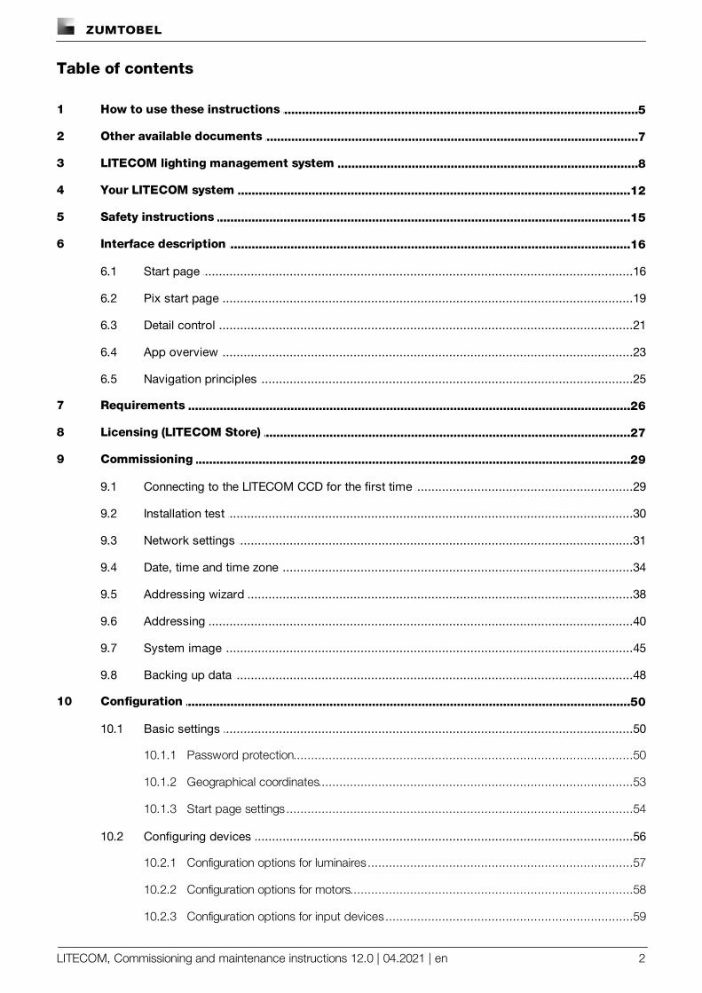
Table of contents
..................................................................................................................................51 How to use these instructions
..................................................................................................................................72 Other available documents
..................................................................................................................................83 LITECOM lighting management system
..................................................................................................................................124 Your LITECOM system
..................................................................................................................................155 Safety instructions
..................................................................................................................................166 Interface description
...............................................................................................................................166.1 Start page
...............................................................................................................................196.2 Pix start page
...............................................................................................................................216.3 Detail control
...............................................................................................................................236.4 App overview
...............................................................................................................................256.5 Navigation principles
..................................................................................................................................267 Requirements
..................................................................................................................................278 Licensing (LITECOM Store)
..................................................................................................................................299 Commissioning
...............................................................................................................................299.1 Connecting to the LITECOM CCD for the first time
...............................................................................................................................309.2 Installation test
...............................................................................................................................319.3 Network settings
...............................................................................................................................349.4 Date, time and time zone
...............................................................................................................................389.5 Addressing wizard
...............................................................................................................................409.6 Addressing
...............................................................................................................................459.7 System image
...............................................................................................................................489.8 Backing up data
..................................................................................................................................5010 Configuration
...............................................................................................................................5010.1 Basic settings
.............................................................................................................50Password protection10.1.1
.............................................................................................................53Geographical coordinates10.1.2
.............................................................................................................54Start page settings10.1.3
...............................................................................................................................5610.2 Configuring devices
.............................................................................................................57Configuration options for luminaires10.2.1
.............................................................................................................58Configuration options for motors10.2.2
.............................................................................................................59Configuration options for input devices10.2.3
3LITECOM, Commissioning and maintenance instructions 12.0 | 04.2021 | en
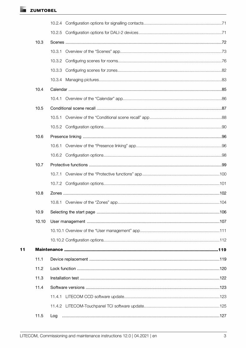
.............................................................................................................71Configuration options for signalling contacts10.2.4
.............................................................................................................71Configuration options for DALI-2 devices10.2.5
...............................................................................................................................7210.3 Scenes
.............................................................................................................73Overview of the “Scenes” app10.3.1
.............................................................................................................76Configuring scenes for rooms10.3.2
.............................................................................................................82Configuring scenes for zones10.3.3
.............................................................................................................83Managing pictures10.3.4
...............................................................................................................................8510.4 Calendar
.............................................................................................................86Overview of the “Calendar” app10.4.1
...............................................................................................................................8710.5 Conditional scene recall
.............................................................................................................88Overview of the “Conditional scene recall” app10.5.1
.............................................................................................................90Configuration options10.5.2
...............................................................................................................................9610.6 Presence linking
.............................................................................................................96Overview of the “Presence linking” app10.6.1
.............................................................................................................98Configuration options10.6.2
...............................................................................................................................9910.7 Protective functions
.............................................................................................................100Overview of the “Protective functions” app10.7.1
.............................................................................................................101Configuration options10.7.2
...............................................................................................................................10210.8 Zones
.............................................................................................................104Overview of the “Zones” app10.8.1
...............................................................................................................................10610.9 Selecting the start page
...............................................................................................................................10710.10 User management
.............................................................................................................111Overview of the “User management” app10.10.1
.............................................................................................................112Configuration options10.10.2
..................................................................................................................................11911 Maintenance
...............................................................................................................................11911.1 Device replacement
...............................................................................................................................12011.2 Lock function
...............................................................................................................................12211.3 Installation test
...............................................................................................................................12311.4 Software versions
.............................................................................................................123LITECOM CCD software update11.4.1
.............................................................................................................125LITECOM-Touchpanel TCI software update11.4.2
...............................................................................................................................12711.5 Log
4LITECOM, Commissioning and maintenance instructions 12.0 | 04.2021 | en
...............................................................................................................................12811.6 Faults
...............................................................................................................................12911.7 Data backup
..................................................................................................................................13512 Appendix
...............................................................................................................................13512.1 Factory settings
...............................................................................................................................13612.2 Icons
...............................................................................................................................13812.3 Glossary
How to use these instructions
LITECOM, Commissioning and maintenance instructions 12.0 | 04.2021 | en 5
1 How to use these instructions
We are pleased that you have chosen this Zumtobel Lighting GmbH product. So that you can get the most fromthese instructions, this section provides the following information:
· Signs and icons in these instructions
· Further information
· Target audience of these instructions
· Software version
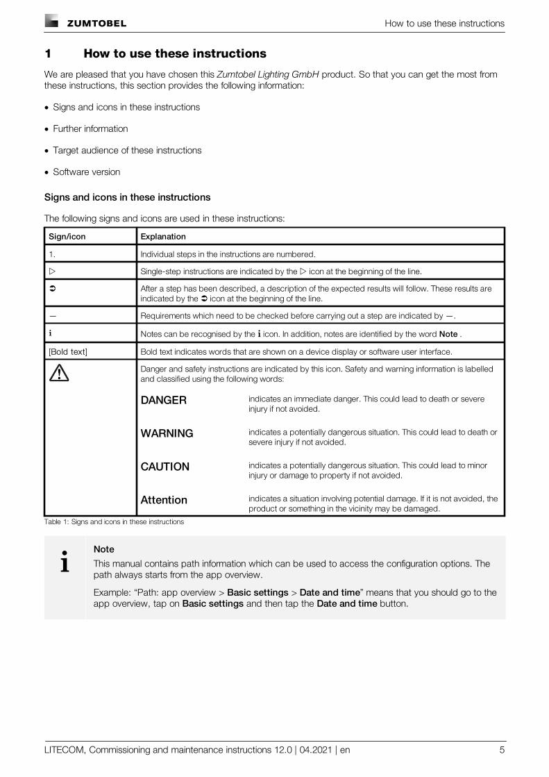
Signs and icons in these instructions
The following signs and icons are used in these instructions:
Sign/icon Explanation
1. Individual steps in the instructions are numbered.
w Single-step instructions are indicated by the w icon at the beginning of the line.
Ü After a step has been described, a description of the expected results will follow. These results areindicated by the Ü icon at the beginning of the line.
— Requirements which need to be checked before carrying out a step are indicated by —.
i Notes can be recognised by the i icon. In addition, notes are identified by the word Note .
[Bold text] Bold text indicates words that are shown on a device display or software user interface.
Danger and safety instructions are indicated by this icon. Safety and warning information is labelledand classified using the following words:
DANGER indicates an immediate danger. This could lead to death or severeinjury if not avoided.
WARNING indicates a potentially dangerous situation. This could lead to death orsevere injury if not avoided.
CAUTION indicates a potentially dangerous situation. This could lead to minorinjury or damage to property if not avoided.
Attention indicates a situation involving potential damage. If it is not avoided, theproduct or something in the vicinity may be damaged.
Table 1: Signs and icons in these instructions
iNote
This manual contains path information which can be used to access the configuration options. Thepath always starts from the app overview.
Example: “Path: app overview > Basic settings > Date and time” means that you should go to theapp overview, tap on Basic settings and then tap the Date and time button.
How to use these instructions
LITECOM, Commissioning and maintenance instructions 12.0 | 04.2021 | en 6
Further information
Further information on the setup and function of your LITECOM system can be found in our product and systemdocumentation.
If you should have any further questions, please contact your sales partner.
General information on our products can be found on our website:www.zumtobel.com
Target audience of these instructions
These instructions are intended for electricians without any special product training who would like to commission LITECOM basic functions. General service functions are also described.
Software version
These instructions are based on software version LITECOM 2.16.0.

Other available documents
LITECOM, Commissioning and maintenance instructions 12.0 | 04.2021 | en 7
2 Other available documents
All LITECOM manuals can be downloaded from the website:http://www.zumtobel.com/gb-en/products/litecom.html
Manual Description
ShowsThis manual is aimed at electricians without any special ZUMTOBELproduct training and describes how shows can be commissionedand configured.
Special luminaires
This manual is aimed at electricians without any special ZUMTOBELproduct training and describes how special luminaires (e.g. RGBluminaires, TW luminaires, SEQUENCE infinity) can be commissionedand configured.
Daylight linkingThis manual is aimed at electricians without any special ZUMTOBELproduct training and describes how daylight linking with light sensorcan be commissioned and configured.
Self-contained emergency luminaires
This manual is aimed at electricians without specific Zumtobelproduct training and describes how emergency lighting functions forself-contained emergency luminaires can be commissioned,configured and monitored in a LITECOM system that itself hasalready been commissioned.
BACnetThis manual is aimed at electricians without any special ZUMTOBELproduct training and describes how BACnet can be commissionedand configured.
Table 2: Other available documents – LITECOM
All LITECOM infinity manuals can be downloaded from the website:http://www.zumtobel.com/gb-en/products/litecom.html
Manual Description
Infinity mode
This manual is intended for individuals (such as electricians andfacility managers) with special Zumtobel product training anddescribes how Infinity mode can be enabled. This is how you getaccess to apps that are only available in Infinity mode and can createan Infinity system out of multiple LITECOM CCDs.
Table 3: Other available documents – LITECOM infinity
LITECOM lighting management system
LITECOM, Commissioning and maintenance instructions 12.0 | 04.2021 | en 8
3 LITECOM lighting management system
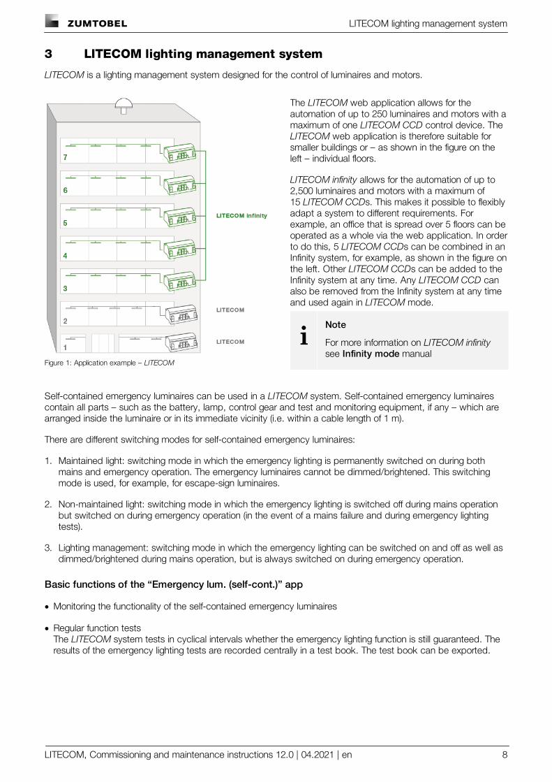
LITECOM is a lighting management system designed for the control of luminaires and motors.
Figure 1: Application example – LITECOM
The LITECOM web application allows for theautomation of up to 250 luminaires and motors with amaximum of one LITECOM CCD control device. TheLITECOM web application is therefore suitable forsmaller buildings or – as shown in the figure on theleft – individual floors.
LITECOM infinity allows for the automation of up to2,500 luminaires and motors with a maximum of15 LITECOM CCDs. This makes it possible to flexiblyadapt a system to different requirements. Forexample, an office that is spread over 5 floors can beoperated as a whole via the web application. In orderto do this, 5 LITECOM CCDs can be combined in anInfinity system, for example, as shown in the figure onthe left. Other LITECOM CCDs can be added to theInfinity system at any time. Any LITECOM CCD canalso be removed from the Infinity system at any timeand used again in LITECOM mode.
iNote
For more information on LITECOM infinitysee Infinity mode manual
Self-contained emergency luminaires can be used in a LITECOM system. Self-contained emergency luminairescontain all parts – such as the battery, lamp, control gear and test and monitoring equipment, if any – which arearranged inside the luminaire or in its immediate vicinity (i.e. within a cable length of 1 m).
There are different switching modes for self-contained emergency luminaires:
1. Maintained light: switching mode in which the emergency lighting is permanently switched on during bothmains and emergency operation. The emergency luminaires cannot be dimmed/brightened. This switchingmode is used, for example, for escape-sign luminaires.
2. Non-maintained light: switching mode in which the emergency lighting is switched off during mains operationbut switched on during emergency operation (in the event of a mains failure and during emergency lightingtests).
3. Lighting management: switching mode in which the emergency lighting can be switched on and off as well asdimmed/brightened during mains operation, but is always switched on during emergency operation.
Basic functions of the “Emergency lum. (self-cont.)” app
· Monitoring the functionality of the self-contained emergency luminaires
· Regular function testsThe LITECOM system tests in cyclical intervals whether the emergency lighting function is still guaranteed. Theresults of the emergency lighting tests are recorded centrally in a test book. The test book can be exported.
LITECOM lighting management system
LITECOM, Commissioning and maintenance instructions 12.0 | 04.2021 | en 9
Integrating self-contained emergency luminaires in a LITECOM system
The following steps are required:
· Step 1: activate the Self-contained emergency luminaires app.Path: App overview > LITECOM Store
· Step 2: address self-contained emergency luminaires.Path: App overview > Addressing > Luminaires
· Step 3: configure the emergency lighting functions.Path: App overview > Emergency lum. (self-cont.) > Settings > Emergency lighting functions
· Step 4: check the emergency lighting functions.Path: App overview > Emergency lum. (self-cont.) > Quick menu > Start function test and Start durationtest
· Step 5: configure self-contained emergency luminaires.Path: App overview > System image > Configure
LITECOM lighting management system
LITECOM, Commissioning and maintenance instructions 12.0 | 04.2021 | en 10
Control options
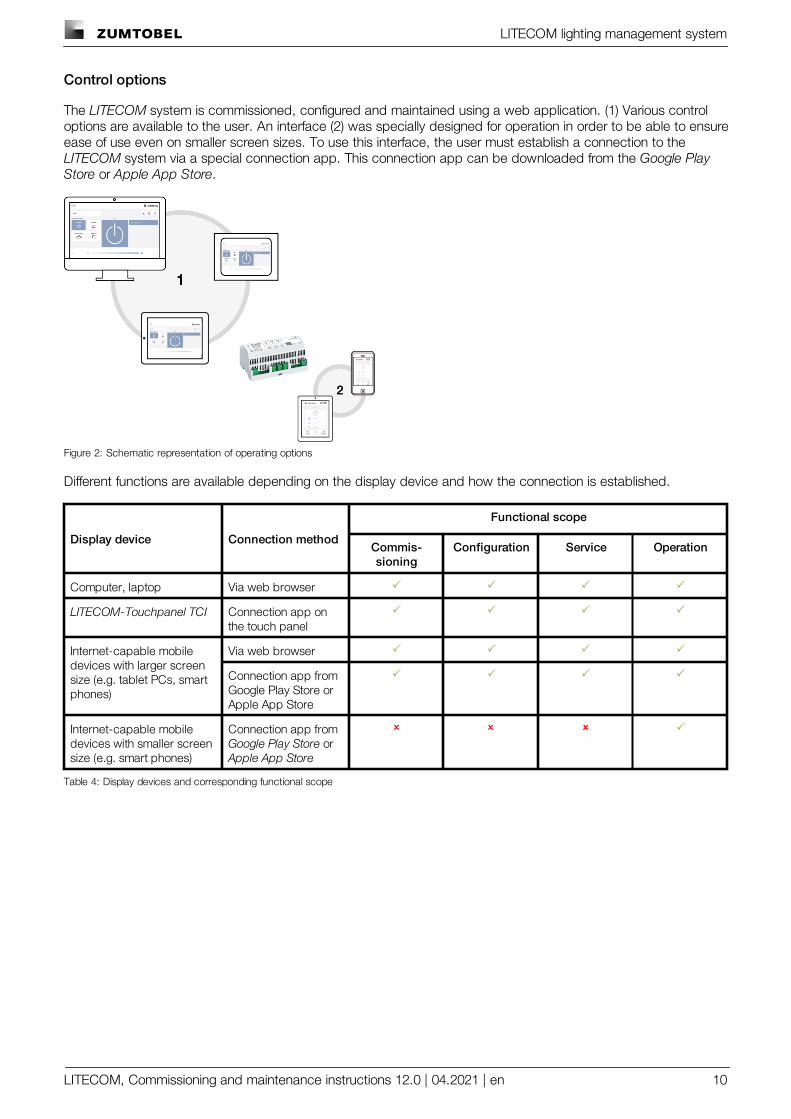
The LITECOM system is commissioned, configured and maintained using a web application. (1) Various controloptions are available to the user. An interface (2) was specially designed for operation in order to be able to ensureease of use even on smaller screen sizes. To use this interface, the user must establish a connection to the LITECOM system via a special connection app. This connection app can be downloaded from the Google PlayStore or Apple App Store.
Figure 2: Schematic representation of operating options
Different functions are available depending on the display device and how the connection is established.
Display device Connection method
Functional scope
Commis-sioning
Configuration Service Operation
Computer, laptop Via web browser P P P P
LITECOM-Touchpanel TCI Connection app onthe touch panel
P P P P
Internet-capable mobiledevices with larger screensize (e.g. tablet PCs, smartphones)
Via web browser P P P P
Connection app fromGoogle Play Store orApple App Store
P P P P
Internet-capable mobiledevices with smaller screensize (e.g. smart phones)
Connection app from Google Play Store orApple App Store
O O O P
Table 4: Display devices and corresponding functional scope
LITECOM lighting management system
LITECOM, Commissioning and maintenance instructions 12.0 | 04.2021 | en 11
Operating system and web browser
The following operating systems and web browsers have been tested and approved for LITECOM V 2.16.0:
· Windows with Google Chrome (version 31 or higher)
· Android 5.0.2 with Google Chrome 46.0
· Android 6.0.1 with Google Chrome 49.0
· iOS 8.1 with Google Chrome 33.0
· iOS 9.2.1 with Google Chrome 49.0
· iOS with Safari
iNote
The LITECOM web application has been optimised for the operating systems and web browsersspecified above. Please note that there may be problems with new versions initially, but these willbe corrected as quickly as possible.
Minimum web browser resolution
The minimum web browser resolution is 800 x 480 px. Please note that this information does not include the menubar.
A correspondingly higher resolution should thus be selected for tablet PCs. Otherwise a scroll bar will be shown inthe web application.
Your LITECOM system
LITECOM, Commissioning and maintenance instructions 12.0 | 04.2021 | en 12
4 Your LITECOM system
Application area
The LITECOM CCD control device is designed to control max. 250 luminaires and motors. There are three DALI-compliant outputs and an LM-Bus interface.
iNote
The LM-Bus is not supplied with power via the LITECOM CCD control device. It requires an externalbus supply: LM-BV (art. No 20 975 247) or LM-BVS35 (art. No 22 115 026).
System limits – hardware
· per LITECOM CCD control device, max. 250 luminaires and motors
· The following emergency luminaires are supported:
Device Type Lamp Available backupdurations
Explanation
EMpowerX LED ExD Maintained light thatcan beswitched/dimmed/brightened
LED · 1 h· 3 h
Standard LEDemergency lightingdevice
EMpower PROset ExD Maintained light thatcan beswitched/dimmed/brightened
LED · 1 h· 3 h
Standard LEDemergency lightingdevice
EM PRO EZ-3 Non-maintained light Fluorescent lamp · 1 h· 3 h
EM converter forfluorescent luminaires
EM PRO G2 Non-maintained light Fluorescent lamp · 1 h· 3 h
EM converter forfluorescent luminaires,follow-on product for EM PRO EZ-3
EM converterLED PRO50 VEM converterLED PRO90 VEM converterLED PRO200 V
Non-maintained light LED · 1 h· 2 h· 3 h
EM converter for LEDluminaires
EM powerLED PROEZ-3, 1 – 2 W
Maintained light thatcan beswitched/dimmed/brightened
LED · 1 h· 2 h· 3 h
EM converter for LEDs,converters from 2015or later are compatible
EM powerLED PROEZ-3, 4 W
Non-maintained light LED · 1 h· 2 h· 3 h
EM converter for LEDs,converters from 2015or later are compatible
Table 5: Supported self-contained emergency luminaires
· per DALI-compliant output, max. 64 DALI addresses or DALI-2 addresses and max. 64 eD addresses
· per DALI-compliant output, guaranteed supply current 200 mA for max. 100 DALI loads
· per DALI-compliant output, max. supply current 250 mA
Your LITECOM system
LITECOM, Commissioning and maintenance instructions 12.0 | 04.2021 | en 13
Line length: LM-Bus
The LITECOM CCD does not have an integrated LM-Bus supply. You need an external bus supply if you wish touse the LM-Bus in your LITECOM system:
· LM-BV (art. no. 20 975 247)
· LM-BVS35 (art. no. 22 115 026)
LM system limits, including line lengths, depend on the bus supply used.
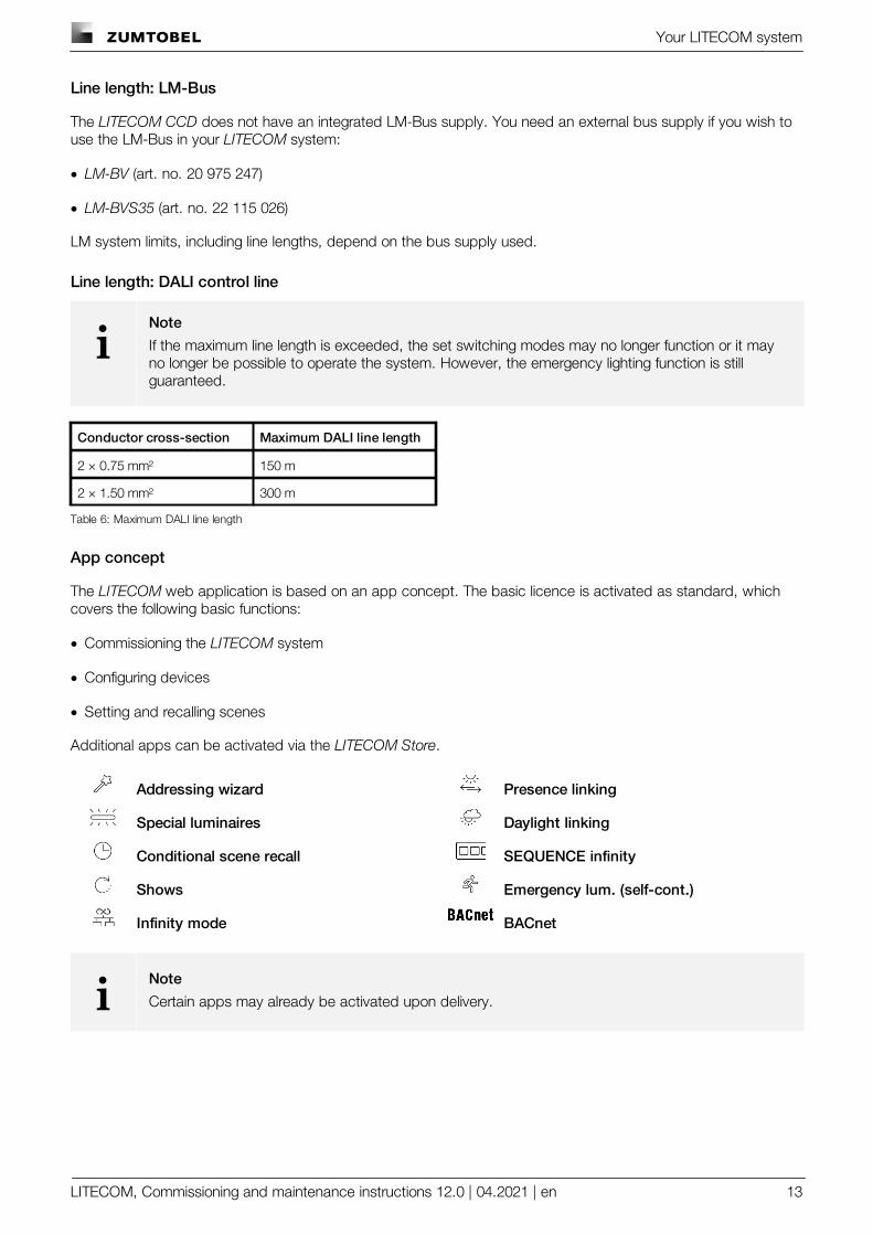
Line length: DALI control line
iNote
If the maximum line length is exceeded, the set switching modes may no longer function or it mayno longer be possible to operate the system. However, the emergency lighting function is stillguaranteed.
Conductor cross-section Maximum DALI line length
2 × 0.75 mm² 150 m
2 × 1.50 mm² 300 m
Table 6: Maximum DALI line length
App concept
The LITECOM web application is based on an app concept. The basic licence is activated as standard, whichcovers the following basic functions:
· Commissioning the LITECOM system
· Configuring devices
· Setting and recalling scenes
Additional apps can be activated via the LITECOM Store.
Addressing wizard Presence linking
Special luminaires Daylight linking
Conditional scene recall SEQUENCE infinity
Shows Emergency lum. (self-cont.)
Infinity mode BACnet
iNote
Certain apps may already be activated upon delivery.
Your LITECOM system
LITECOM, Commissioning and maintenance instructions 12.0 | 04.2021 | en 14
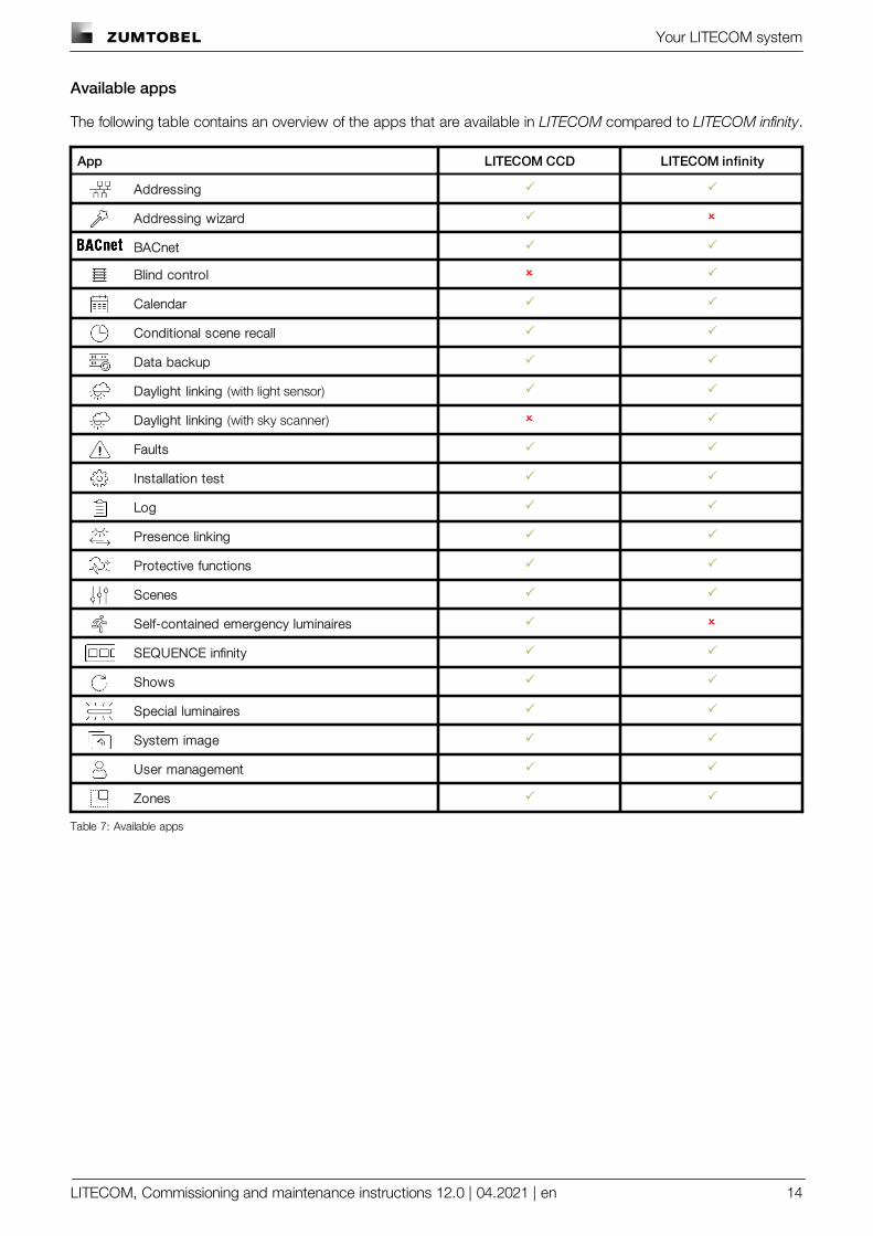
Available apps
The following table contains an overview of the apps that are available in LITECOM compared to LITECOM infinity.
App LITECOM CCD LITECOM infinity
Addressing P P
Addressing wizard P O
BACnet P P
Blind control O P
Calendar P P
Conditional scene recall P P
Data backup P P
Daylight linking (with light sensor) P P
Daylight linking (with sky scanner) O P
Faults P P
Installation test P P
Log P P
Presence linking P P
Protective functions P P
Scenes P P
Self-contained emergency luminaires P O
SEQUENCE infinity P P
Shows P P
Special luminaires P P
System image P P
User management P P
Zones P P
Table 7: Available apps
Safety instructions
LITECOM, Commissioning and maintenance instructions 12.0 | 04.2021 | en 15
5 Safety instructions
Attention· The LITECOM system may only be used for the application area specified.
· Relevant health and safety regulations must be observed.
· Assembly, installation and commissioning may only be carried out by qualified personnel.
· The LITECOM system and connected devices can only be operated when in complete workingorder.
· The manufacturer is neither liable nor does it accept any guarantee for consequential damagethat may occur if these instructions are not followed.
Interface description
LITECOM, Commissioning and maintenance instructions 12.0 | 04.2021 | en 16
6 Interface description
This section contains a description of the interface:
· Start page
· Pix start page
· Detail control
· App overview
· Navigation principles
6.1 Start page
All devices in an effective range (room or zone) can be controlled from the start page.
iNote
If only luminaires (including TW luminaires) are controlled, an alternative start page with a simplifiedoperating concept and limited functional scope is available with Pix.
For more information see Section Pix start page
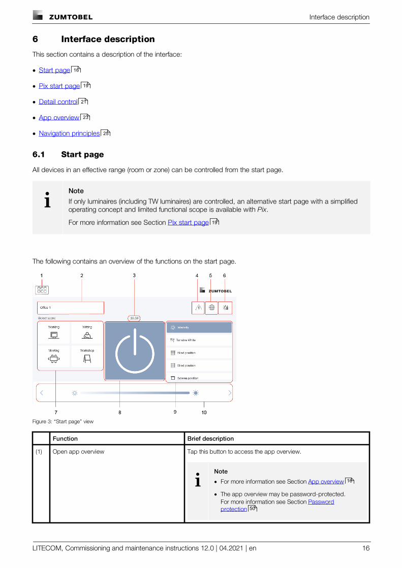
The following contains an overview of the functions on the start page.
Figure 3: “Start page” view
Function Brief description
(1) Open app overview Tap this button to access the app overview.
iNote
· For more information see Section App overview
· The app overview may be password-protected.For more information see Section Passwordprotection
16
19
21
23
25
19
16
50
Interface description
LITECOM, Commissioning and maintenance instructions 12.0 | 04.2021 | en 17
Function Brief description
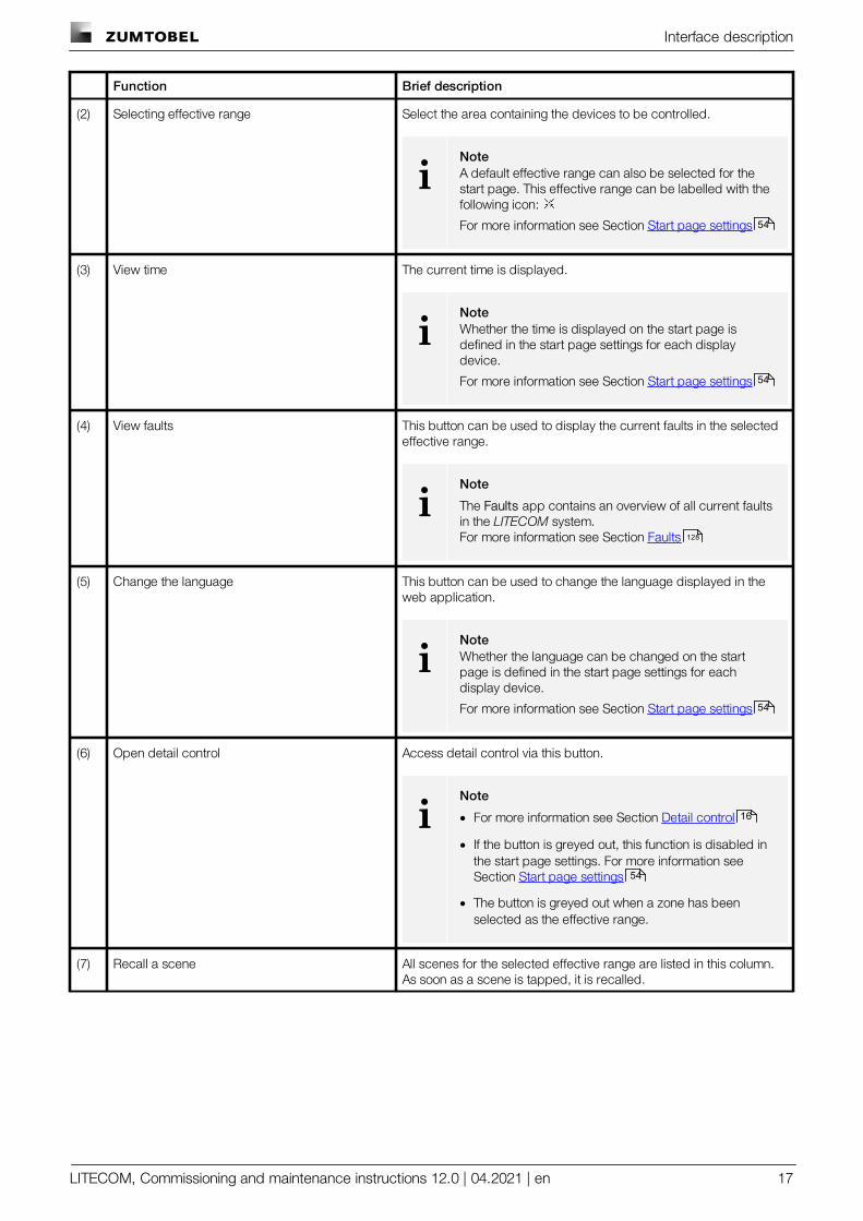
(2) Selecting effective range Select the area containing the devices to be controlled.
iNoteA default effective range can also be selected for thestart page. This effective range can be labelled with thefollowing icon:
For more information see Section Start page settings
(3) View time The current time is displayed.
iNoteWhether the time is displayed on the start page isdefined in the start page settings for each displaydevice.
For more information see Section Start page settings
(4) View faults This button can be used to display the current faults in the selectedeffective range.
iNote
The Faults app contains an overview of all current faultsin the LITECOM system.For more information see Section Faults
(5) Change the language This button can be used to change the language displayed in theweb application.
iNoteWhether the language can be changed on the startpage is defined in the start page settings for eachdisplay device.
For more information see Section Start page settings
(6) Open detail control Access detail control via this button.
iNote
· For more information see Section Detail control
· If the button is greyed out, this function is disabled inthe start page settings. For more information seeSection Start page settings
· The button is greyed out when a zone has beenselected as the effective range.
(7) Recall a scene All scenes for the selected effective range are listed in this column.As soon as a scene is tapped, it is recalled.
54
54
128
54
16
54
Interface description
LITECOM, Commissioning and maintenance instructions 12.0 | 04.2021 | en 18
Function Brief description
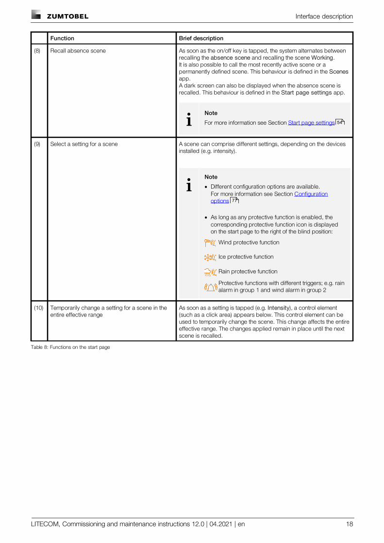
(8) Recall absence scene As soon as the on/off key is tapped, the system alternates betweenrecalling the absence scene and recalling the scene Working.It is also possible to call the most recently active scene or apermanently defined scene. This behaviour is defined in the Scenesapp.A dark screen can also be displayed when the absence scene isrecalled. This behaviour is defined in the Start page settings app.
iNote
For more information see Section Start page settings
(9) Select a setting for a scene A scene can comprise different settings, depending on the devicesinstalled (e.g. intensity).
iNote
· Different configuration options are available.For more information see Section Configurationoptions
· As long as any protective function is enabled, thecorresponding protective function icon is displayedon the start page to the right of the blind position:
Wind protective function
Ice protective function
Rain protective function
Protective functions with different triggers; e.g. rainalarm in group 1 and wind alarm in group 2
(10) Temporarily change a setting for a scene in theentire effective range
As soon as a setting is tapped (e.g. Intensity), a control element(such as a click area) appears below. This control element can beused to temporarily change the scene. This change affects the entireeffective range. The changes applied remain in place until the nextscene is recalled.
Table 8: Functions on the start page
54
77
Interface description
LITECOM, Commissioning and maintenance instructions 12.0 | 04.2021 | en 19
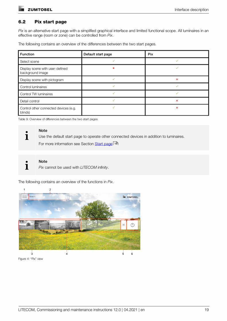
6.2 Pix start page
Pix is an alternative start page with a simplified graphical interface and limited functional scope. All luminaires in aneffective range (room or zone) can be controlled from Pix.
The following contains an overview of the differences between the two start pages.
Function Default start page Pix
Select scene P P
Display scene with user-definedbackground image
O P
Display scene with pictogram P O
Control luminaires P P
Control TW luminaires P P
Detail control P O
Control other connected devices (e.g.blinds)
P O
Table 9: Overview of differences between the two start pages
iNote
Use the default start page to operate other connected devices in addition to luminaires.
For more information see Section Start page
iNote
Pix cannot be used with LITECOM infinity.
The following contains an overview of the functions in Pix.
Figure 4: “Pix” view
16
Interface description
LITECOM, Commissioning and maintenance instructions 12.0 | 04.2021 | en 20
Function Brief description
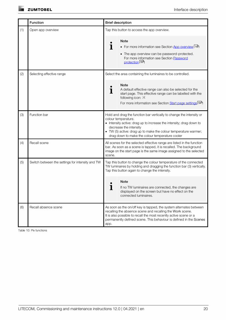
(1) Open app overview Tap this button to access the app overview.
iNote
· For more information see Section App overview
· The app overview can be password-protected.For more information see Section Passwordprotection
(2) Selecting effective range Select the area containing the luminaires to be controlled.
iNoteA default effective range can also be selected for thestart page. This effective range can be labelled with thefollowing icon:
For more information see Section Start page settings
(3) Function bar Hold and drag the function bar vertically to change the intensity orcolour temperature.· Intensity active: drag up to increase the intensity; drag down to
decrease the intensity· TW (5) active: drag up to make the colour temperature warmer;
drag down to make the colour temperature cooler
(4) Recall scene All scenes for the selected effective range are listed in the functionbar. As soon as a scene is tapped, it is recalled. The backgroundimage on the start page is the same image assigned to the selectedscene.
(5) Switch between the settings for intensity and TW Tap this button to change the colour temperature of the connectedTW luminaires by holding and dragging the function bar (3) vertically.Tap this button again to change the intensity.
iNote
If no TW luminaires are connected, the changes aredisplayed on the screen but have no effect on theconnected luminaires.
(6) Recall absence scene As soon as the on/off key is tapped, the system alternates betweenrecalling the absence scene and recalling the Work scene.It is also possible to recall the most recently active scene or apermanently defined scene. This behaviour is defined in the Scenesapp.
Table 10: Pix functions
16
50
54
Interface description
LITECOM, Commissioning and maintenance instructions 12.0 | 04.2021 | en 21
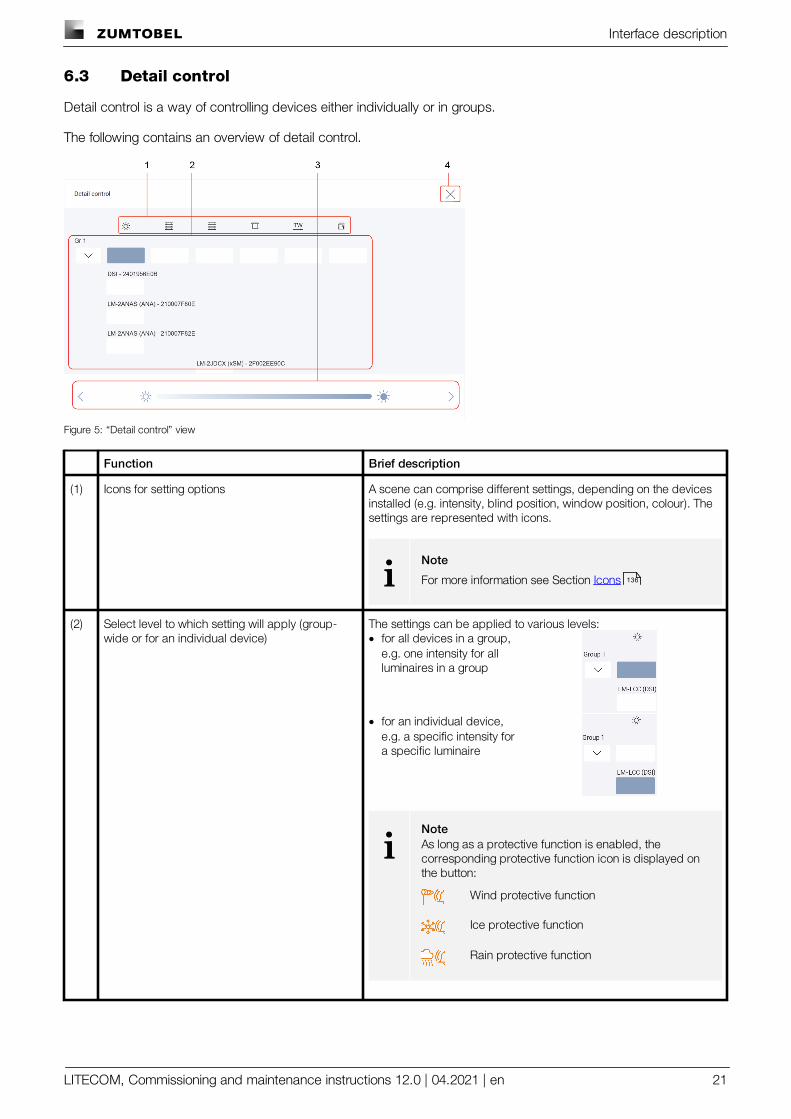
6.3 Detail control
Detail control is a way of controlling devices either individually or in groups.
The following contains an overview of detail control.
Figure 5: “Detail control” view
Function Brief description
(1) Icons for setting options A scene can comprise different settings, depending on the devicesinstalled (e.g. intensity, blind position, window position, colour). Thesettings are represented with icons.
iNote
For more information see Section Icons
(2) Select level to which setting will apply (group-wide or for an individual device)
The settings can be applied to various levels:· for all devices in a group,
e.g. one intensity for allluminaires in a group
· for an individual device,e.g. a specific intensity fora specific luminaire
iNoteAs long as a protective function is enabled, thecorresponding protective function icon is displayed onthe button:
Wind protective function
Ice protective function
Rain protective function
136
Interface description
LITECOM, Commissioning and maintenance instructions 12.0 | 04.2021 | en 22
Function Brief description
(3) Temporarily change a scene via control element As soon as a button is tapped (e.g. intensity at device level), a controlelement (such as a slider) appears below. For certain devices (suchas special luminaires) multiple control elements appear. Thesecontrol elements can be used to temporarily change the scene. Thechanges applied remain in place until the next scene is recalled.
(4) Exit detail control Tap the cross (X symbol) to exit detail control and go to the startpage. The changes applied remain in place until the next scene isrecalled.
Table 11: Detail control functions
Interface description
LITECOM, Commissioning and maintenance instructions 12.0 | 04.2021 | en 23
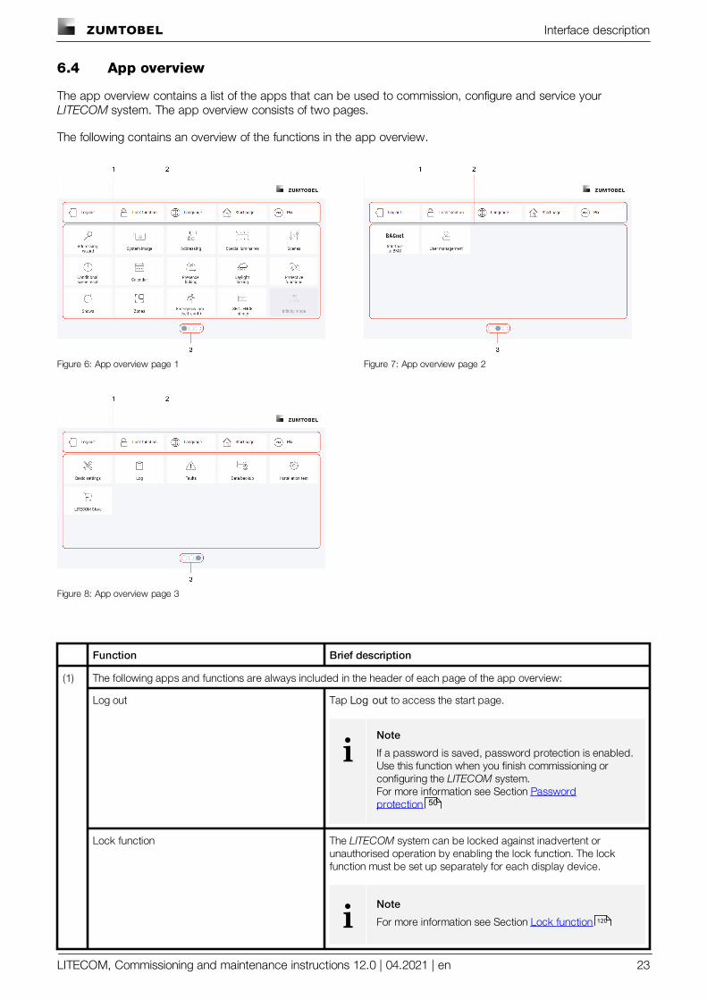
6.4 App overview
The app overview contains a list of the apps that can be used to commission, configure and service your LITECOM system. The app overview consists of two pages.
The following contains an overview of the functions in the app overview.
Figure 6: App overview page 1 Figure 7: App overview page 2
Figure 8: App overview page 3
Function Brief description
(1) The following apps and functions are always included in the header of each page of the app overview:
Log out Tap Log out to access the start page.
iNote
If a password is saved, password protection is enabled.Use this function when you finish commissioning orconfiguring the LITECOM system.For more information see Section Passwordprotection
Lock function The LITECOM system can be locked against inadvertent orunauthorised operation by enabling the lock function. The lockfunction must be set up separately for each display device.
iNote
For more information see Section Lock function
50
120
Interface description
LITECOM, Commissioning and maintenance instructions 12.0 | 04.2021 | en 24
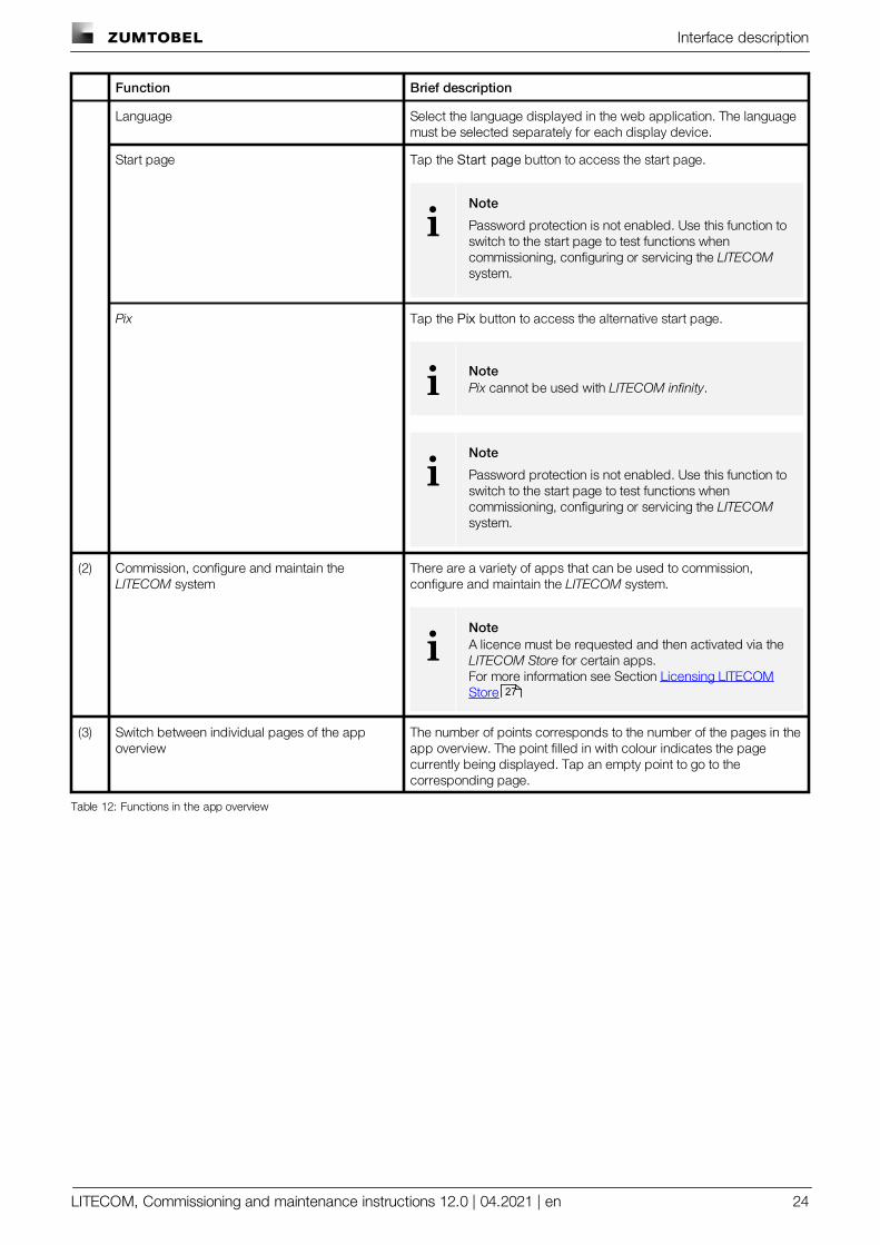
Function Brief description
Language Select the language displayed in the web application. The languagemust be selected separately for each display device.
Start page Tap the Start page button to access the start page.
iNote
Password protection is not enabled. Use this function toswitch to the start page to test functions whencommissioning, configuring or servicing the LITECOMsystem.
Pix Tap the Pix button to access the alternative start page.
i NotePix cannot be used with LITECOM infinity.
iNote
Password protection is not enabled. Use this function toswitch to the start page to test functions whencommissioning, configuring or servicing the LITECOMsystem.
(2) Commission, configure and maintain the LITECOM system
There are a variety of apps that can be used to commission,configure and maintain the LITECOM system.
iNoteA licence must be requested and then activated via the LITECOM Store for certain apps.For more information see Section Licensing LITECOMStore
(3) Switch between individual pages of the appoverview
The number of points corresponds to the number of the pages in theapp overview. The point filled in with colour indicates the pagecurrently being displayed. Tap an empty point to go to thecorresponding page.
Table 12: Functions in the app overview
27

Interface description
LITECOM, Commissioning and maintenance instructions 12.0 | 04.2021 | en 25
6.5 Navigation principles
There are different buttons in the web application for commissioning, configuring and operating the system. If abutton is tapped, its colour changes briefly.
Button Description
Set value (e.g. on the start page)You can enter a specific value in the click area so that all devices have the samecontrol value.If, for example, different control values (80%, 60%) are set for the luminaires andyou tap on 50%, all luminaires switch to the control value of 50%.
If you tap on the left or right click area, the value you are setting decreases orincreases respectively in the entire effective range by one unit. If different controlvalues are saved for the luminaires (80%, 60%, 20%) and you tap on the button,these control values are increased by one unit (81%, 61%, 21%). This function is notavailable for all setting options.
Set value (e.g. fade time)Tap these buttons to increase or decrease the value being set. Tap the button tochange the value by one unit. Tap and hold the button to change the value, andrelease when the desired value has been reached. The longer the button is held,the faster the value is changed.
Special feature: set the timeIf the time is tapped, the Set time view appears. The hours and minutes can be setseparately here.
Expand – collapseThe arrow indicates that additional information or selection options can bedisplayed (e.g. devices in a group).Tap the arrow pointing right to expand the information or selection options. Thearrow changes so that it is pointing down.Tap the arrow pointing down to collapse the information or selection options. Thearrow changes so that it is pointing right again.
Save or confirmTap this button to save the settings or confirm a message.
Option not selected – option selected (single choice)This button marks multiple options that are available (e.g. different types of dategroups), from which only one can be selected. As soon as an option for a switch isselected, all other switches change to the other option accordingly.
Option not selected – option selected (multiple choice)This button marks multiple options that are available, from which multiple optionscan be selected. As soon as an option is selected, it is highlighted.
Setting not selected – setting selectedif an empty button is tapped (e.g. blind position at device level), the button is filled inwith colour. One or more control elements (such as sliders) appear below.
Switch between individual pages of the app overviewThe number of points corresponds to the number of the pages in the app overview.The point filled in with colour indicates the page currently being displayed. Tap anempty point to go to the corresponding page.
Tap the logo to access the Information view. This page contains manufacturerinformation, the reference number and version of the web application andinformation on the licences used.
Table 13: Navigation principles

Requirements
LITECOM, Commissioning and maintenance instructions 12.0 | 04.2021 | en 26
7 Requirements
Before starting the commissioning and configuration process for your LITECOM system, ensure that the followingrequirements have been met.
— LITECOM CCD control device and display device (touch panel, computer) are connected via an Ethernetcable.
– or –
— LITECOM CCD control device and display device (touch panel, computer, mobile device) are connected via awireless access point.
— The following settings are stored for the display device and wireless access point:
o IP address . . . . . . . . .10.10.40.2 – 10.10.40.253
o Subnet mask . . . . . .255.255.0.0
— The LITECOM CCD control device must have hardware batch B3 as a minimum.
iNote
The hardware batch can be found on the batch label of the LITECOM CCD in the second position;e.g. V2.00 B3A M17.
— The LITECOM platform must be updated to version 2.2.1-B3 or higher.Path: App overview > Basic settings > Software versions > LITECOM CCD
— The software version must be updated to version 2.16.0.Path: App overview > Basic settings > Software versions
Licensing (LITECOM Store)
LITECOM, Commissioning and maintenance instructions 12.0 | 04.2021 | en 27
8 Licensing (LITECOM Store)
Certain apps may be disabled in the LITECOM CCD web application because the licences in question have notbeen activated. To activate an app, a licence must be requested and then activated via the LITECOM Store.
Path: App overview > LITECOM Store
The LITECOM web application comes with the basic licence activated as standard. It contains the following apps:
System image Basic settings
Addressing Logging
Scenes Faults
Calendar Data backup
Protective functions Installation test
Zones LITECOM Store
User management
Additional apps can be activated via the LITECOM Store.
Addressing wizard Presence linking
Special luminaires Daylight linking
Conditional scene recall SEQUENCE infinity
Shows Emergency lum. (self-cont.)
Infinity mode BACnet
iNote
Certain apps may already be activated upon delivery.
iNote
You only need the Basic licence (Infinity) if you want to use LITECOM in Infinity mode.For more information on LITECOM infinity see Infinity mode manual
Licensing (LITECOM Store)
LITECOM, Commissioning and maintenance instructions 12.0 | 04.2021 | en 28
You have to activate the licence before you can use a licensed App.
The following steps are required:
· Step 1: request licence.Path: App overview > LITECOM Store > Licensing information
· Step 2: activate licence.Path: App overview > LITECOM Store > Activate licence
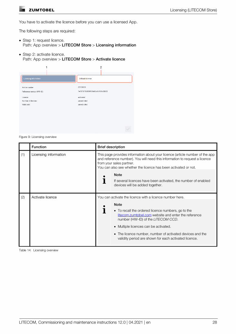
Figure 9: Licensing overview
Function Brief description
(1) Licensing information This page provides information about your licence (article number of the appand reference number). You will need this information to request a licencefrom your sales partner.You can also see whether the licence has been activated or not.
iNote
If several licences have been activated, the number of enableddevices will be added together.
(2) Activate licence You can activate the licence with a licence number here.
iNote
· To recall the ordered licence numbers, go to the litecom.zumtobel.com website and enter the referencenumber (HW-ID) of the LITECOM CCD.
· Multiple licences can be activated.
· The licence number, number of activated devices and thevalidity period are shown for each activated licence.
Table 14: Licensing overview
Commissioning
LITECOM, Commissioning and maintenance instructions 12.0 | 04.2021 | en 29
9 Commissioning
LITECOM system commissioning comprises the following parts:
· Connecting to the LITECOM CCD control device for the first time
· Testing the installation
· Testing the network settings
· Setting the date, time and time zone
· Running the addressing wizard to create rooms and groups and address devices
iNote
· The addressing wizard guides the user through the individual steps of addressing and providesrelated assistance.
· Alternatively, rooms and groups can be created via the System image app and then devices canbe addressed using the Addressing app.For more information see Section System image or Addressing
· Backing up data
As soon as commissioning is complete the installed luminaires can be controlled.
9.1 Connecting to the LITECOM CCD for the first time
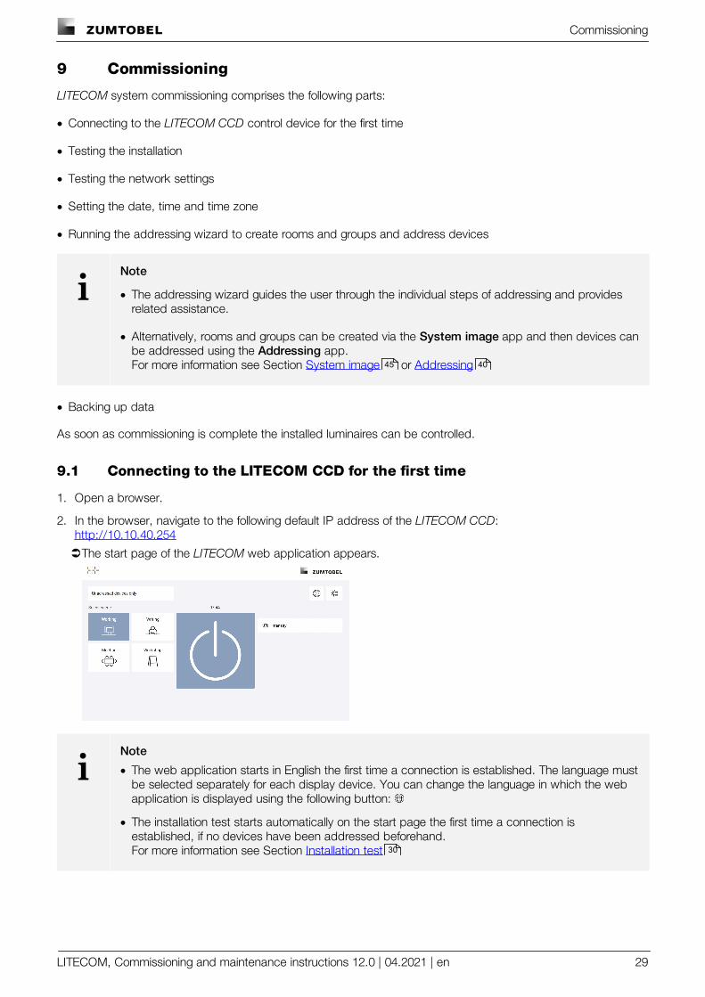
1. Open a browser.
2. In the browser, navigate to the following default IP address of the LITECOM CCD:http://10.10.40.254
ÜThe start page of the LITECOM web application appears.
iNote
· The web application starts in English the first time a connection is established. The language mustbe selected separately for each display device. You can change the language in which the webapplication is displayed using the following button:
· The installation test starts automatically on the start page the first time a connection isestablished, if no devices have been addressed beforehand.For more information see Section Installation test
45 40
30
Commissioning
LITECOM, Commissioning and maintenance instructions 12.0 | 04.2021 | en 30
9.2 Installation test
Test the electrical installation of the LITECOM system. The installation test starts automatically on the start pagethe first time a connection is established, if no devices have been addressed beforehand.
iNote
You can start an installation test manually at any time. This is recommended when devices arereplaced or new devices are added, for example.Path: App overview > Installation testFor more information see Section Installation test
The installation test affects all unaddressed devices.
Testing the installation
Requirement:
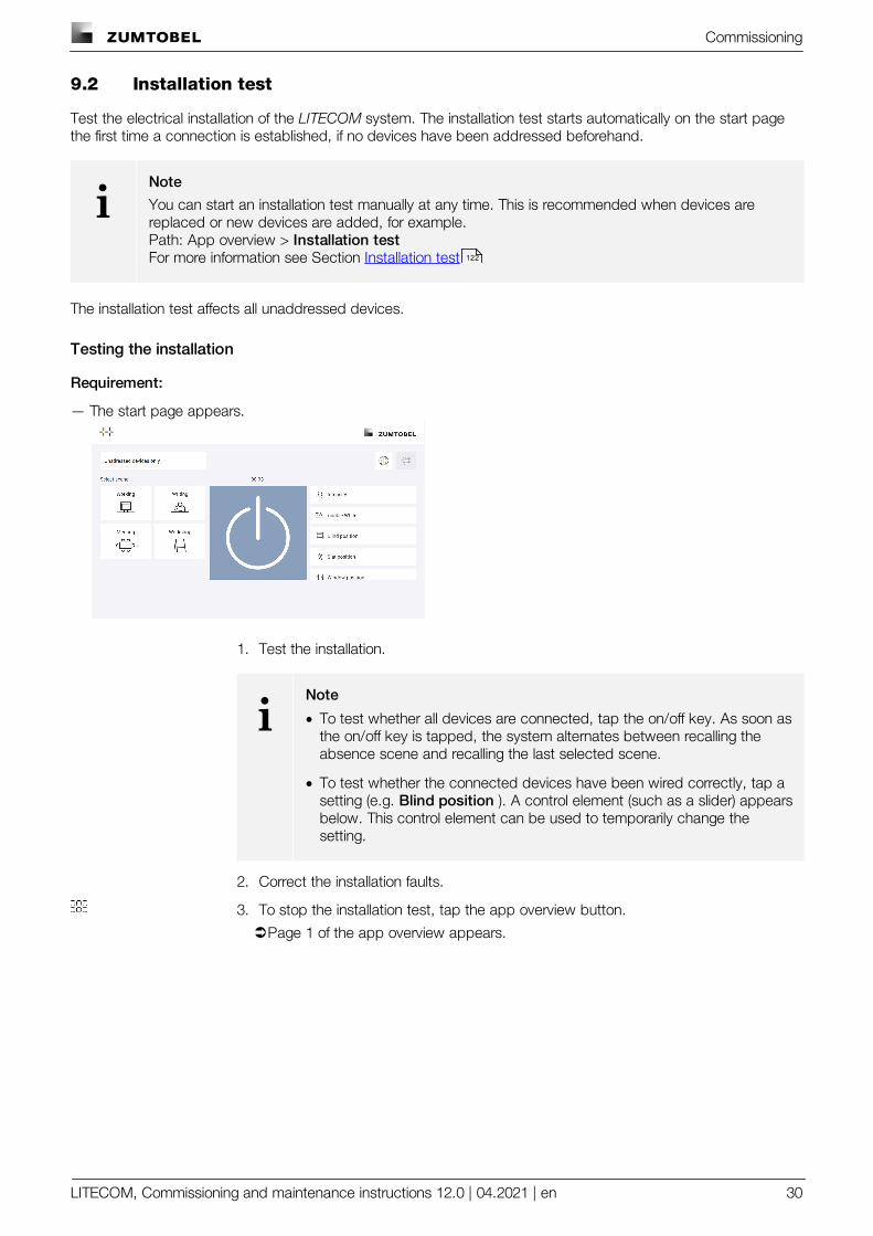
— The start page appears.
1. Test the installation.
iNote
· To test whether all devices are connected, tap the on/off key. As soon asthe on/off key is tapped, the system alternates between recalling theabsence scene and recalling the last selected scene.
· To test whether the connected devices have been wired correctly, tap asetting (e.g. Blind position ). A control element (such as a slider) appearsbelow. This control element can be used to temporarily change thesetting.
2. Correct the installation faults.
3. To stop the installation test, tap the app overview button.
ÜPage 1 of the app overview appears.
122
Commissioning
LITECOM, Commissioning and maintenance instructions 12.0 | 04.2021 | en 31
9.3 Network settings
You can define whether the LITECOM CCD control device uses a static IP address or obtains an IP addressautomatically. A static IP address is assigned by default.
iNote
The following default settings are stored in the LITECOM CCD:
· Default IP address of the LITECOM CCD: 10.10.40.254
· Default subnet mask: 255.255.0.0
Changing the device name and device designation
You can change the device name of the LITECOM CCD. The device name is LITECOM CCD by default. TheLITECOM-Touchpanel TCI and the LITECOM Mobile App use this device name to establish a connection to theLITECOM CCD. For better assignment we recommend allocating a unique name to the LITECOM CCD installedon your LITECOM system (e.g. LITECOM CCD ground floor). You can also change the device designation of theLITECOM CCD. The device designation is a short form of device name that is used in an Infinity system in order touniquely assign the RGA address of a device (e.g. luminaire) to a control device.
iNote
· The maximum length of the device designation is four characters, e.g.
o LC01 as a short form for LITECOM CCD 01.
o 0001 as short form for the first LITECOM CCD in general.
o GF01 as a short form for the first LITECOM CCD on the ground floor.
Commissioning
LITECOM, Commissioning and maintenance instructions 12.0 | 04.2021 | en 32
Changing the static IP address
iNote
The new IP address must be located in the same IP address range in order for the web applicationto automatically be redirected to the new IP address. Example:
· Old IP address: 10.10.40.254
· New IP address: 10.10.40.201
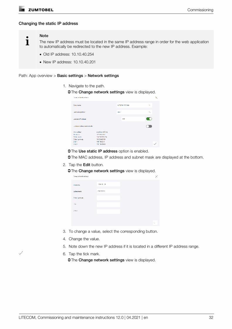
Path: App overview > Basic settings > Network settings
1. Navigate to the path.
ÜThe Change network settings view is displayed.
ÜThe Use static IP address option is enabled.
ÜThe MAC address, IP address and subnet mask are displayed at the bottom.
2. Tap the Edit button.
ÜThe Change network settings view is displayed.
3. To change a value, select the corresponding button.
4. Change the value.
5. Note down the new IP address if it is located in a different IP address range.
6. Tap the tick mark.
ÜThe Change network settings view is displayed.
Commissioning
LITECOM, Commissioning and maintenance instructions 12.0 | 04.2021 | en 33
7. As soon as all the required data has been changed, tap the tick mark.
ÜThe changes are saved.
ÜIf the old and new IP address are located in the same IP address range, the webapplication is automatically redirected to the new IP address.– or –
ÜIf the old and new IP address are located in different IP address ranges, the webapplication is not automatically redirected to the new IP address. A correspondingmessage is displayed.
iNote
wOpen the web application in the browser by navigating to the new IPaddress.
Obtaining an IP address automatically
If a DHCP server is installed on your network, the LITECOM CCD control device can obtain the IP addressautomatically via the server. The advantages this provides are that the IP address does not already have to havebeen assigned on the network and that possible IP address conflicts are automatically resolved.
Path: App overview > Basic settings > Network settings
1. Navigate to the path.
ÜThe Change network settings view is displayed.
2. Enable Obtain IP address automatically option.
ÜThe MAC address is displayed at the bottom.
3. Tap the tick mark.
ÜThe changes are saved.
ÜThe web application is not automatically redirected to the new IP address. Acorresponding message is displayed.
4. Request a new IP address from your IT department.
5. Open the web application in the browser by navigating to the new IP address.
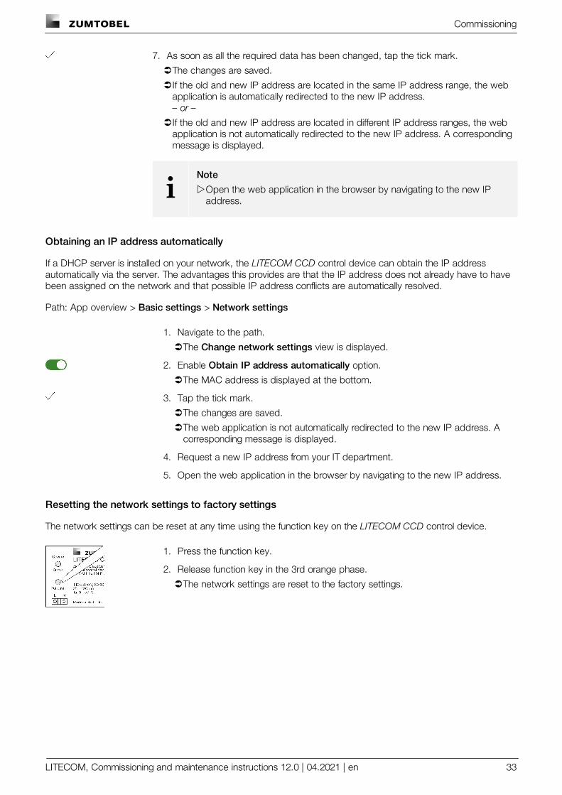
Resetting the network settings to factory settings
The network settings can be reset at any time using the function key on the LITECOM CCD control device.
1. Press the function key.
2. Release function key in the 3rd orange phase.
ÜThe network settings are reset to the factory settings.
Commissioning
LITECOM, Commissioning and maintenance instructions 12.0 | 04.2021 | en 34
9.4 Date, time and time zone
The date and time are used as the basis for all time linking (e.g. conditional scene recall at a specific time) and fortimestamps for test book and log entries.
Path: App overview > Basic settings > Date and time
iNote
The date and time are automatically changed depending on the time zone. For this reason, werecommend proceeding as follows to set the date, time and time zone:
1. Open the Date and time app.
2. Set the time zone.
3. Tap the tick mark.
ÜThe changes are saved.
ÜThe LITECOM CCD is restarted. This process may take several minutes. Then start page isthen displayed.
4. Open the Date and time app again.
5. Set the date.
6. Set the time.
7. Tap the tick mark.
ÜThe changes are saved.
ÜThe Basic settings view is displayed.
Commissioning
LITECOM, Commissioning and maintenance instructions 12.0 | 04.2021 | en 35
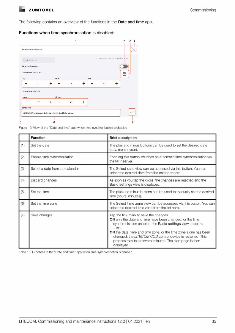
The following contains an overview of the functions in the Date and time app.
Functions when time synchronisation is disabled:
Figure 10: View of the “Date and time” app when time synchronisation is disabled
Function Brief description
(1) Set the date The plus and minus buttons can be used to set the desired date(day, month, year).
(2) Enable time synchronisation Enabling this button switches on automatic time synchronisation viathe NTP server.
(3) Select a date from the calendar The Select date view can be accessed via this button. You canselect the desired date from the calendar here.
(4) Discard changes As soon as you tap the cross, the changes are rejected and the Basic settings view is displayed.
(5) Set the time The plus and minus buttons can be used to manually set the desiredtime (hours, minutes).
(6) Set the time zone The Select time zone view can be accessed via this button. You canselect the desired time zone from the list here.
(7) Save changes Tap the tick mark to save the changes.Ü If only the date and time have been changed, or the time
synchronisation enabled, the Basic settings view appears.– or –
Ü If the date, time and time zone, or the time zone alone has beenchanged, the LITECOM CCD control device is restarted. Thisprocess may take several minutes. The start page is thendisplayed.
Table 15: Functions in the “Date and time” app when time synchronisation is disabled
Commissioning
LITECOM, Commissioning and maintenance instructions 12.0 | 04.2021 | en 36
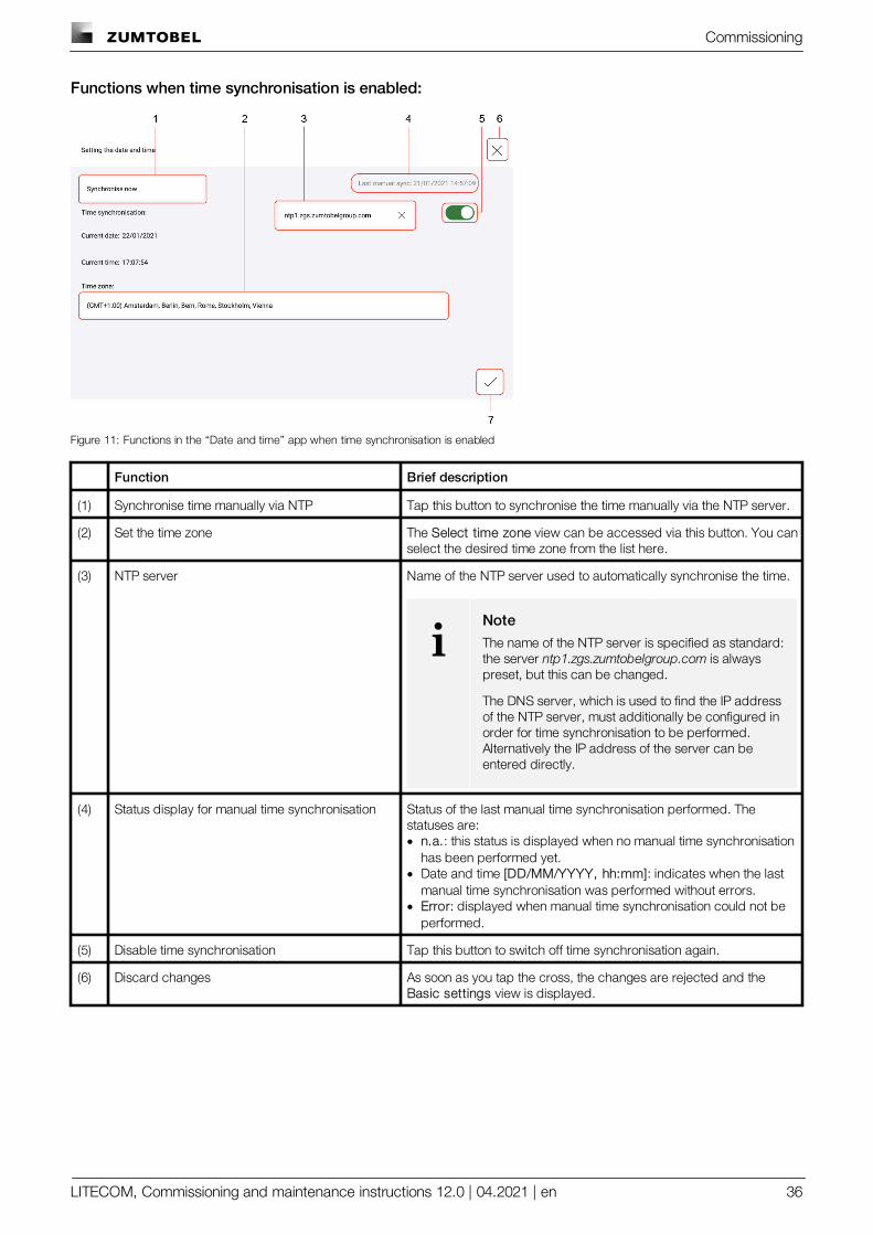
Functions when time synchronisation is enabled:
Figure 11: Functions in the “Date and time” app when time synchronisation is enabled
Function Brief description
(1) Synchronise time manually via NTP Tap this button to synchronise the time manually via the NTP server.
(2) Set the time zone The Select time zone view can be accessed via this button. You canselect the desired time zone from the list here.
(3) NTP server Name of the NTP server used to automatically synchronise the time.
iNoteThe name of the NTP server is specified as standard:the server ntp1.zgs.zumtobelgroup.com is alwayspreset, but this can be changed.
The DNS server, which is used to find the IP addressof the NTP server, must additionally be configured inorder for time synchronisation to be performed.Alternatively the IP address of the server can beentered directly.
(4) Status display for manual time synchronisation Status of the last manual time synchronisation performed. Thestatuses are:· n.a.: this status is displayed when no manual time synchronisation
has been performed yet.· Date and time [DD/MM/YYYY, hh:mm]: indicates when the last
manual time synchronisation was performed without errors.· Error: displayed when manual time synchronisation could not be
performed.
(5) Disable time synchronisation Tap this button to switch off time synchronisation again.
(6) Discard changes As soon as you tap the cross, the changes are rejected and the Basic settings view is displayed.
Commissioning
LITECOM, Commissioning and maintenance instructions 12.0 | 04.2021 | en 37
Function Brief description
(7) Save changes Tap the tick mark to save the changes.Ü If only the date and time have been changed, or the time
synchronisation disabled, the Basic settings view appears.– or –
Ü If the date, time and time zone, or the time zone alone has beenchanged, the LITECOM CCD control device is restarted. Thisprocess may take several minutes. The start page is thendisplayed.
Table 16: Functions in the “Date and time” app when time synchronisation is enabled
Commissioning
LITECOM, Commissioning and maintenance instructions 12.0 | 04.2021 | en 38
9.5 Addressing wizard
Devices can be controlled individually, by group or by room with your LITECOM system.
To do this, a system image must be created and the devices must be addressed. The system image is a list-likerepresentation of the LITECOM system in the web application. It contains rooms, groups and the devices installedin the system. In addition – if available – zones and the addressed control equipment therein are also displayed.
The device is identified using its production number during addressing. The device is then assigned to a room anda group.
The addressing wizard guides the user through the individual steps of addressing and provides related assistance.
Path: App overview > Addressing wizard
iNote
You can also use the addressing wizard for system extensions. During a system extension, deviceswhich are new in an existing, addressed system are addressed. Addressing for previouslyaddressed devices will remain unchanged.
Running the addressing wizard
Requirement:
— The Addressing wizard app is activated.Path: App overview > LITECOM Store > Addressing wizard
Path: App overview > Addressing wizard
1. Navigate to the path.
ÜThe addressing wizard starts.
2. Follow the addressing wizard instructions.
Commissioning
LITECOM, Commissioning and maintenance instructions 12.0 | 04.2021 | en 39
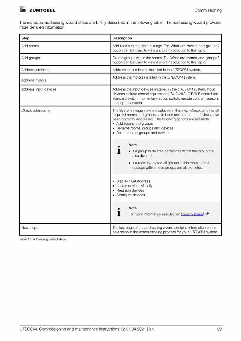
The individual addressing wizard steps are briefly described in the following table. The addressing wizard providesmore detailed information.
Step Description
Add rooms Add rooms to the system image. The What are rooms and groups?button can be used to view a short introduction to this topic.
Add groups Create groups within the rooms. The What are rooms and groups?button can be used to view a short introduction to this topic.
Address luminaires Address the luminaires installed in the LITECOM system.
Address motorsAddress the motors installed in the LITECOM system.
Address input devices Address the input devices installed in the LITECOM system. Inputdevices include control equipment (LM-CIRIA, CIRCLE control unit,standard switch, momentary-action switch, remote control), sensorsand input contacts.
Check addressing The System image view is displayed in this step. Check whether allrequired rooms and groups have been added and the devices havebeen correctly addressed. The following options are available:· Add rooms and groups· Rename rooms, groups and devices· Delete rooms, groups and devices
iNote
· If a group is deleted all devices within this group arealso deleted.
· If a room is deleted all groups in this room and alldevices within these groups are also deleted.
· Display RGA address· Locate devices visually· Reassign devices· Configure devices
iNote
For more information see Section System image
Next steps The last page of the addressing wizard contains information on thenext steps in the commissioning process for your LITECOM system.
Table 17: Addressing wizard steps
45
Commissioning
LITECOM, Commissioning and maintenance instructions 12.0 | 04.2021 | en 40
9.6 Addressing
Addressing is the sum of the processes needed so that each electronic network and bus subscriber is given anindividual RGA address (room address/group address/own address). The combination of processes differs fromdevice to device.
Path: App overview > Addressing
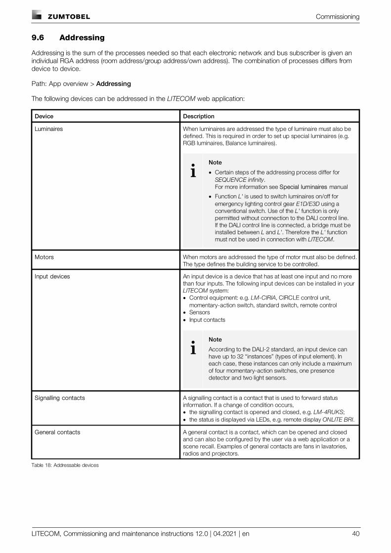
The following devices can be addressed in the LITECOM web application:
Device Description
Luminaires When luminaires are addressed the type of luminaire must also bedefined. This is required in order to set up special luminaires (e.g.RGB luminaires, Balance luminaires).
iNote
· Certain steps of the addressing process differ for SEQUENCE infinity.For more information see Special luminaires manual
· Function L' is used to switch luminaires on/off foremergency lighting control gear E1D/E3D using aconventional switch. Use of the L' function is onlypermitted without connection to the DALI control line.If the DALI control line is connected, a bridge must beinstalled between L and L'. Therefore the L' functionmust not be used in connection with LITECOM.
Motors When motors are addressed the type of motor must also be defined.The type defines the building service to be controlled.
Input devices An input device is a device that has at least one input and no morethan four inputs. The following input devices can be installed in your LITECOM system:· Control equipment: e.g. LM-CIRIA, CIRCLE control unit,
momentary-action switch, standard switch, remote control· Sensors· Input contacts
iNote
According to the DALI-2 standard, an input device canhave up to 32 “instances” (types of input element). Ineach case, these instances can only include a maximumof four momentary-action switches, one presencedetector and two light sensors.
Signalling contacts A signalling contact is a contact that is used to forward statusinformation. If a change of condition occurs,· the signalling contact is opened and closed, e.g. LM-4RUKS;· the status is displayed via LEDs, e.g. remote display ONLITE BRI.
General contacts A general contact is a contact, which can be opened and closedand can also be configured by the user via a web application or ascene recall. Examples of general contacts are fans in lavatories,radios and projectors.
Table 18: Addressable devices
Commissioning
LITECOM, Commissioning and maintenance instructions 12.0 | 04.2021 | en 41
General procedure for addressing in the LITECOM web application
1. Select device category to be addressed (e.g. luminaires).
2. The location method must also be selected for input devices: Select actively (Physical Selection method) orSearch via interface (locate).
3. Locate the device in the field.More information can be found here...
4. A type is assigned to the device.The type is automatically selected, if possible.More information can be found here...
5. Assign a room and a group to the device.
6. Optionally, change the device name.
iNote
· We recommend using the addressing wizard to address the devices.For more information see Section Addressing wizard
· Every time there is a change on a DALI control line or on the LM-Bus the affected LITECOM CCDcontrol device must be restarted in order for the changed field to be imported correctly.
More information about location
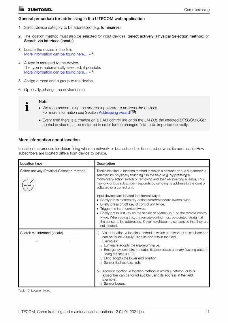
Location is a process for determining where a network or bus subscriber is located or what its address is. Howsubscribers are located differs from device to device.
Location type Description
Select actively (Physical Selection method) Tactile location: a location method in which a network or bus subscriber isselected by physically touching it in the field (e.g. by pressing amomentary-action switch or removing and then re-inserting a lamp). Thisnetwork or bus subscriber responds by sending its address to the controlsoftware or a control unit.
Input devices are located in different ways:· Briefly press momentary-action switch/standard switch twice.· Briefly press on/off key of control unit twice.· Trigger the input contact twice.· Briefly press test key on the sensor or scene key 1 on the remote control
twice. When doing this, the remote control must be pointed straight atthe sensor to be addressed. Cover neighbouring sensors so that they arenot located.
Search via interface (locate) a) Visual location: a location method in which a network or bus subscribercan be found visually using its address in the field.Examples:o Luminaire adopts the maximum value.o Emergency luminaire indicates its address as a binary flashing pattern
using the status LED.o Blind adopts the lower end position.o Sensor flashes (e.g. red).
b) Acoustic location: a location method in which a network or bussubscriber can be found audibly using its address in the field.Example:o Sensor beeps.
Table 19: Location types
40
40
38
Commissioning
LITECOM, Commissioning and maintenance instructions 12.0 | 04.2021 | en 42
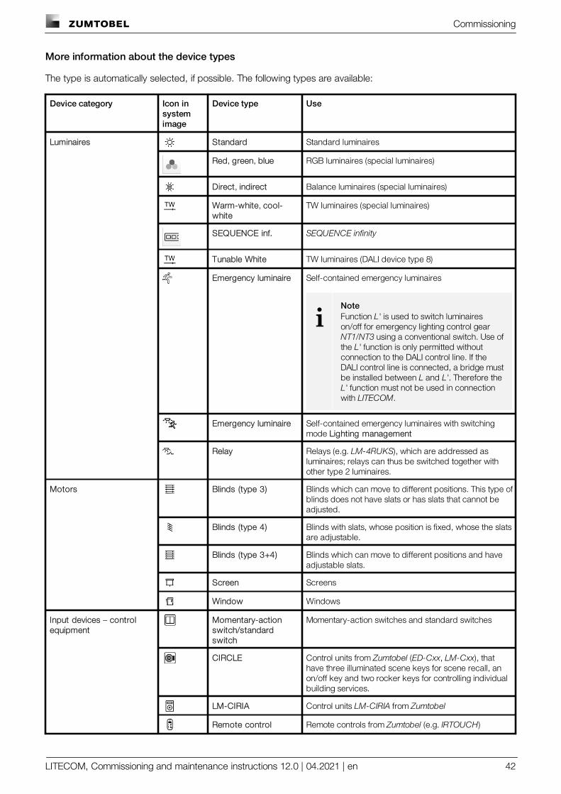
More information about the device types
The type is automatically selected, if possible. The following types are available:
Device category Icon insystemimage
Device type Use
Luminaires Standard Standard luminaires
Red, green, blue RGB luminaires (special luminaires)
Direct, indirect Balance luminaires (special luminaires)
Warm-white, cool-white
TW luminaires (special luminaires)
SEQUENCE inf. SEQUENCE infinity
Tunable White TW luminaires (DALI device type 8)
Emergency luminaire Self-contained emergency luminaires
iNoteFunction L' is used to switch luminaireson/off for emergency lighting control gear NT1/NT3 using a conventional switch. Use ofthe L' function is only permitted withoutconnection to the DALI control line. If theDALI control line is connected, a bridge mustbe installed between L and L'. Therefore theL' function must not be used in connectionwith LITECOM.
Emergency luminaire Self-contained emergency luminaires with switchingmode Lighting management
Relay Relays (e.g. LM-4RUKS), which are addressed asluminaires; relays can thus be switched together withother type 2 luminaires.
Motors Blinds (type 3) Blinds which can move to different positions. This type ofblinds does not have slats or has slats that cannot beadjusted.
Blinds (type 4) Blinds with slats, whose position is fixed, whose the slatsare adjustable.
Blinds (type 3+4) Blinds which can move to different positions and haveadjustable slats.
Screen Screens
Window Windows
Input devices – controlequipment
Momentary-actionswitch/standardswitch
Momentary-action switches and standard switches
CIRCLE Control units from Zumtobel (ED-Cxx, LM-Cxx), thathave three illuminated scene keys for scene recall, anon/off key and two rocker keys for controlling individualbuilding services.
LM-CIRIA Control units LM-CIRIA from Zumtobel
Remote control Remote controls from Zumtobel (e.g. IRTOUCH)
Commissioning
LITECOM, Commissioning and maintenance instructions 12.0 | 04.2021 | en 43
Device category Icon insystemimage
Device type Use
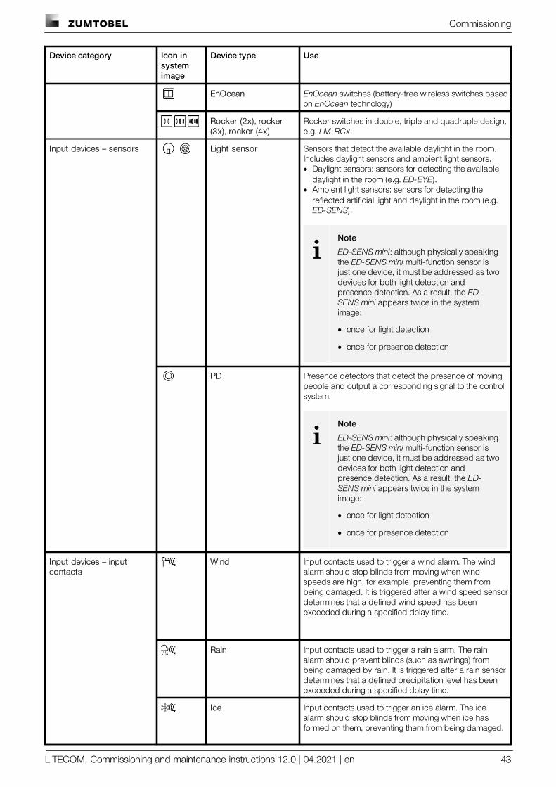
EnOcean EnOcean switches (battery-free wireless switches basedon EnOcean technology)
Rocker (2x), rocker(3x), rocker (4x)
Rocker switches in double, triple and quadruple design,e.g. LM-RCx.
Input devices – sensors Light sensor Sensors that detect the available daylight in the room.Includes daylight sensors and ambient light sensors.· Daylight sensors: sensors for detecting the available
daylight in the room (e.g. ED-EYE).· Ambient light sensors: sensors for detecting the
reflected artificial light and daylight in the room (e.g. ED-SENS).
iNote
ED-SENS mini: although physically speakingthe ED-SENS mini multi-function sensor isjust one device, it must be addressed as twodevices for both light detection andpresence detection. As a result, the ED-SENS mini appears twice in the systemimage:
· once for light detection
· once for presence detection
PD Presence detectors that detect the presence of movingpeople and output a corresponding signal to the controlsystem.
iNote
ED-SENS mini: although physically speakingthe ED-SENS mini multi-function sensor isjust one device, it must be addressed as twodevices for both light detection andpresence detection. As a result, the ED-SENS mini appears twice in the systemimage:
· once for light detection
· once for presence detection
Input devices – inputcontacts
Wind Input contacts used to trigger a wind alarm. The windalarm should stop blinds from moving when windspeeds are high, for example, preventing them frombeing damaged. It is triggered after a wind speed sensordetermines that a defined wind speed has beenexceeded during a specified delay time.
Rain Input contacts used to trigger a rain alarm. The rainalarm should prevent blinds (such as awnings) frombeing damaged by rain. It is triggered after a rain sensordetermines that a defined precipitation level has beenexceeded during a specified delay time.
Ice Input contacts used to trigger an ice alarm. The icealarm should stop blinds from moving when ice hasformed on them, preventing them from being damaged.
Commissioning
LITECOM, Commissioning and maintenance instructions 12.0 | 04.2021 | en 44
Device category Icon insystemimage
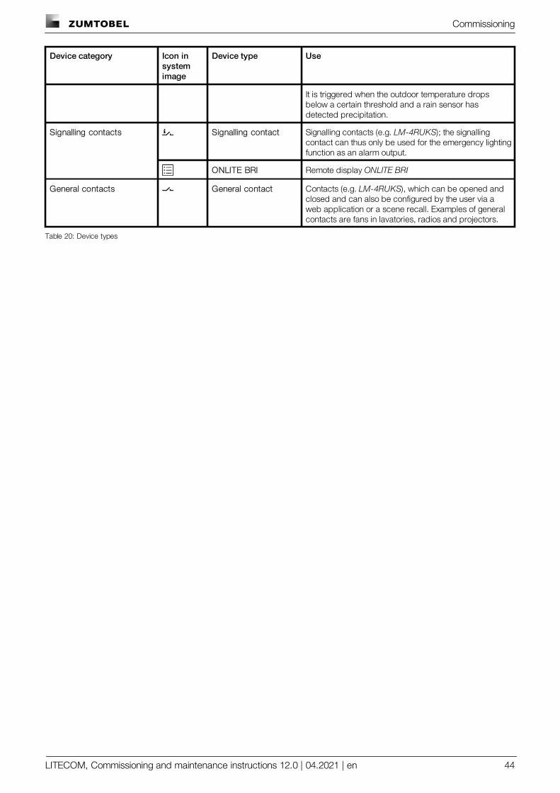
Device type Use
It is triggered when the outdoor temperature dropsbelow a certain threshold and a rain sensor hasdetected precipitation.
Signalling contacts Signalling contact Signalling contacts (e.g. LM-4RUKS); the signallingcontact can thus only be used for the emergency lightingfunction as an alarm output.
ONLITE BRI Remote display ONLITE BRI
General contacts General contact Contacts (e.g. LM-4RUKS), which can be opened andclosed and can also be configured by the user via aweb application or a scene recall. Examples of generalcontacts are fans in lavatories, radios and projectors.
Table 20: Device types
Commissioning
LITECOM, Commissioning and maintenance instructions 12.0 | 04.2021 | en 45
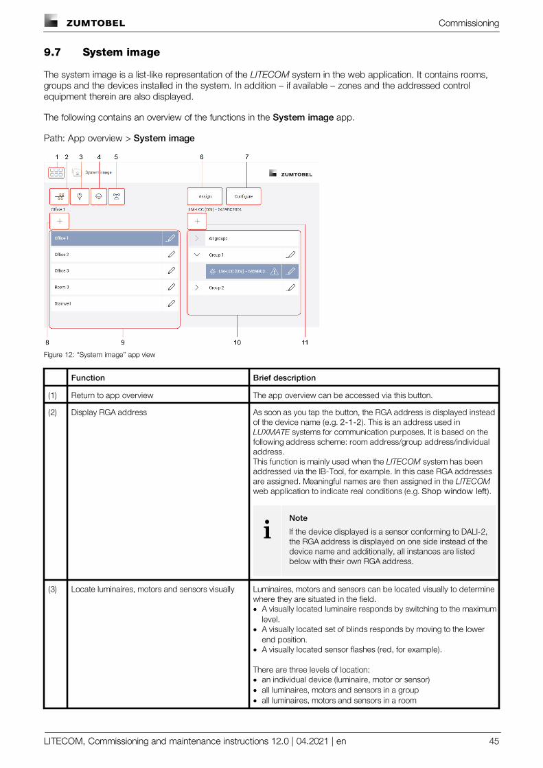
9.7 System image
The system image is a list-like representation of the LITECOM system in the web application. It contains rooms,groups and the devices installed in the system. In addition – if available – zones and the addressed controlequipment therein are also displayed.
The following contains an overview of the functions in the System image app.
Path: App overview > System image
Figure 12: “System image” app view
Function Brief description
(1) Return to app overview The app overview can be accessed via this button.
(2) Display RGA address As soon as you tap the button, the RGA address is displayed insteadof the device name (e.g. 2-1-2). This is an address used inLUXMATE systems for communication purposes. It is based on thefollowing address scheme: room address/group address/individualaddress. This function is mainly used when the LITECOM system has beenaddressed via the IB-Tool, for example. In this case RGA addressesare assigned. Meaningful names are then assigned in the LITECOMweb application to indicate real conditions (e.g. Shop window left).
iNote
If the device displayed is a sensor conforming to DALI-2,the RGA address is displayed on one side instead of thedevice name and additionally, all instances are listedbelow with their own RGA address.
(3) Locate luminaires, motors and sensors visually Luminaires, motors and sensors can be located visually to determinewhere they are situated in the field.· A visually located luminaire responds by switching to the maximum
level.· A visually located set of blinds responds by moving to the lower
end position.· A visually located sensor flashes (red, for example).
There are three levels of location:· an individual device (luminaire, motor or sensor)· all luminaires, motors and sensors in a group· all luminaires, motors and sensors in a room
Commissioning
LITECOM, Commissioning and maintenance instructions 12.0 | 04.2021 | en 46
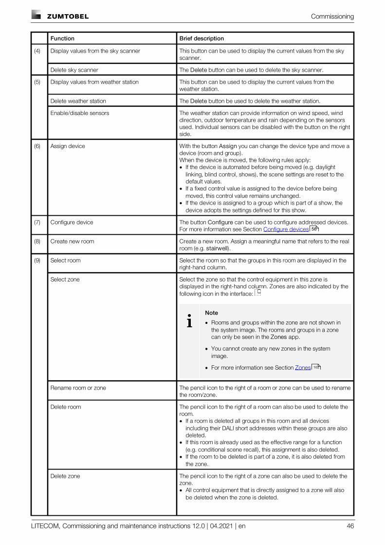
Function Brief description
(4) Display values from the sky scanner This button can be used to display the current values from the skyscanner.
Delete sky scanner The Delete button can be used to delete the sky scanner.
(5) Display values from weather station This button can be used to display the current values from theweather station.
Delete weather station The Delete button be used to delete the weather station.
Enable/disable sensors The weather station can provide information on wind speed, winddirection, outdoor temperature and rain depending on the sensorsused. Individual sensors can be disabled with the button on the rightside.
(6) Assign device With the button Assign you can change the device type and move adevice (room and group).When the device is moved, the following rules apply:· If the device is automated before being moved (e.g. daylight
linking, blind control, shows), the scene settings are reset to thedefault values.
· If a fixed control value is assigned to the device before beingmoved, this control value remains unchanged.
· If the device is assigned to a group which is part of a show, thedevice adopts the settings defined for this show.
(7) Configure device The button Configure can be used to configure addressed devices.For more information see Section Configure devices
(8) Create new room Create a new room. Assign a meaningful name that refers to the realroom (e.g. stairwell).
(9) Select room Select the room so that the groups in this room are displayed in theright-hand column.
Select zone Select the zone so that the control equipment in this zone isdisplayed in the right-hand column. Zones are also indicated by thefollowing icon in the interface:
iNote
· Rooms and groups within the zone are not shown inthe system image. The rooms and groups in a zonecan only be seen in the Zones app.
· You cannot create any new zones in the systemimage.
· For more information see Section Zones
Rename room or zone The pencil icon to the right of a room or zone can be used to renamethe room/zone.
Delete room The pencil icon to the right of a room can also be used to delete theroom. · If a room is deleted all groups in this room and all devices
including their DALI short addresses within these groups are alsodeleted.
· If this room is already used as the effective range for a function(e.g. conditional scene recall), this assignment is also deleted.
· If the room to be deleted is part of a zone, it is also deleted fromthe zone.
Delete zone The pencil icon to the right of a zone can also be used to delete thezone.· All control equipment that is directly assigned to a zone will also
be deleted when the zone is deleted.
56
102
Commissioning
LITECOM, Commissioning and maintenance instructions 12.0 | 04.2021 | en 47
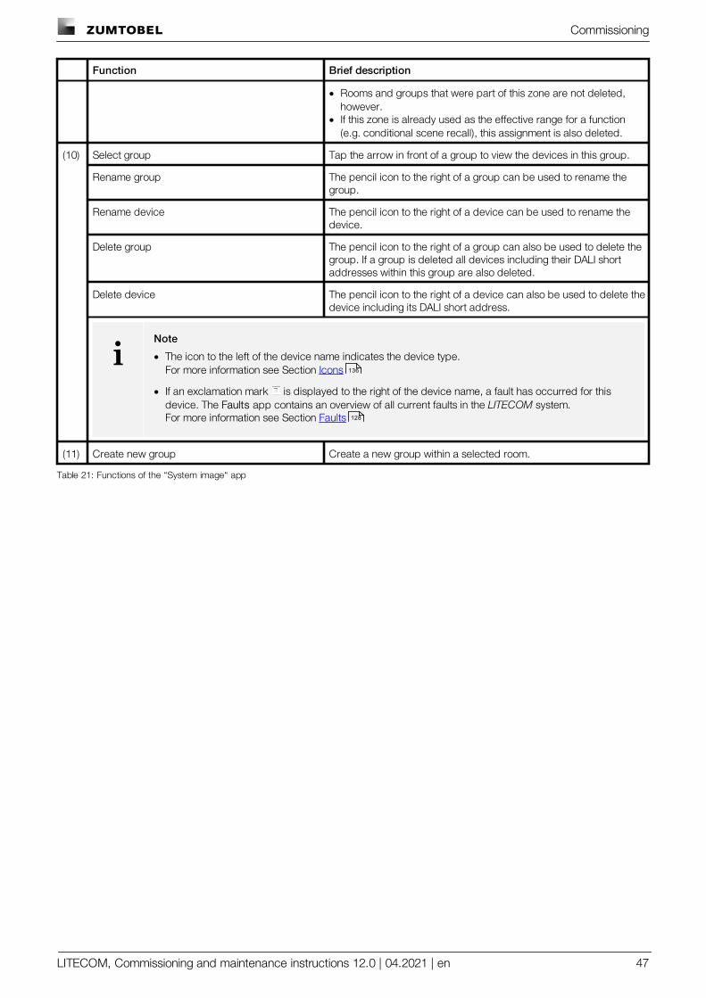
Function Brief description
· Rooms and groups that were part of this zone are not deleted,however.
· If this zone is already used as the effective range for a function(e.g. conditional scene recall), this assignment is also deleted.
(10) Select group Tap the arrow in front of a group to view the devices in this group.
Rename group The pencil icon to the right of a group can be used to rename thegroup.
Rename device The pencil icon to the right of a device can be used to rename thedevice.
Delete group The pencil icon to the right of a group can also be used to delete thegroup. If a group is deleted all devices including their DALI shortaddresses within this group are also deleted.
Delete device The pencil icon to the right of a device can also be used to delete thedevice including its DALI short address.
iNote
· The icon to the left of the device name indicates the device type.For more information see Section Icons
· If an exclamation mark is displayed to the right of the device name, a fault has occurred for thisdevice. The Faults app contains an overview of all current faults in the LITECOM system.For more information see Section Faults
(11) Create new group Create a new group within a selected room.
Table 21: Functions of the “System image“ app
136
128
Commissioning
LITECOM, Commissioning and maintenance instructions 12.0 | 04.2021 | en 48
9.8 Backing up data
LITECOM offers different types of data backup: a complete data backup or a partial data backup.
· Complete data backup: the complete data backup is saved on the computer or on a mobile device andcontains more information than a partial data backup. The complete data backup provides the advantage ofbeing able to restore the data of the LITECOM system in full if data loss occurs (e.g. due to a faultyLITECOM CCD control device).
· Partial data backup: the partial data backup is saved locally on the LITECOM CCD and only includes theconfiguration of the LITECOM system (e.g. system image, scenes, conditional scene recall, presence linking). Itis suitable for restoring a previous version of the system after a reconfiguration.
We therefore recommend storing a complete data backup on your computer once commissioning is finished.
Path: App overview > Data backup
iNote
For more information see Section Data backup
Backing up data (complete data backup)
iNote
This function is not supported by display devices with iOS operating systems.
Requirement:
— LITECOM CCD control device and computer are connected via an Ethernet cable.
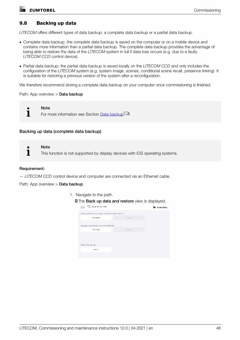
Path: App overview > Data backup
1. Navigate to the path.
ÜThe Back up data and restore view is displayed.
129
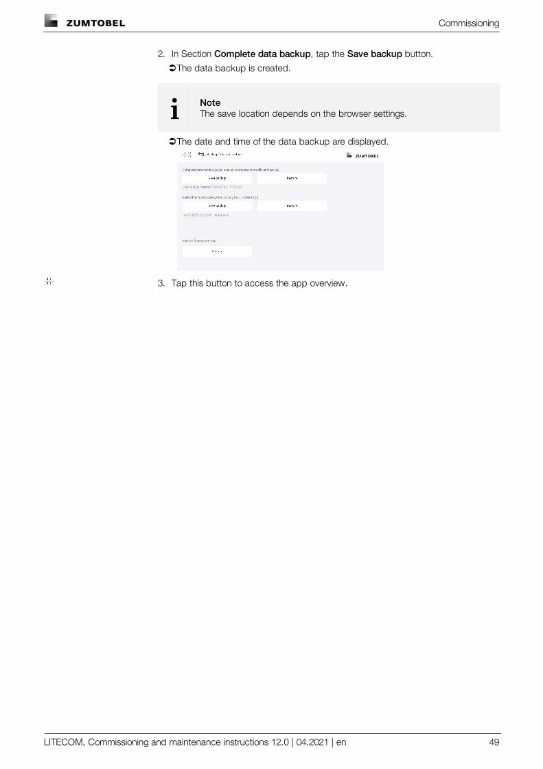
Commissioning
LITECOM, Commissioning and maintenance instructions 12.0 | 04.2021 | en 49
2. In Section Complete data backup, tap the Save backup button.
ÜThe data backup is created.
i NoteThe save location depends on the browser settings.
ÜThe date and time of the data backup are displayed.
3. Tap this button to access the app overview.
Configuration
LITECOM, Commissioning and maintenance instructions 12.0 | 04.2021 | en 50
10 Configuration
After commissioning, additional settings can be defined in order to adapt the LITECOM system to your on-siterequirements.
iNote
Certain apps may be disabled in the LITECOM web application because the licences in questionhave not been activated. To activate an app, a licence must be requested and then activated viathe LITECOM Store.
10.1 Basic settings
Path: App overview > Basic settings
In addition to the basic settings which were defined during commissioning, the Basic settings app provides thefollowing additional basic settings:
· Password protection
· Geographical coordinates
· Start page settings
10.1.1 Password protection
The LITECOM system can be locked against inadvertent or unauthorised configuration by enabling passwordprotection.
Path: App overview > Basic settings > Password protection
iNote
To lock the LITECOM system against inadvertent or unauthorised operation, use the lock function.For more information see Section Lock function
Password protection is disabled by default (i.e. no password is set). As soon as a password is set, passwordprotection is enabled and the app overview can only be accessed once the password has been entered.
50
53
54
120
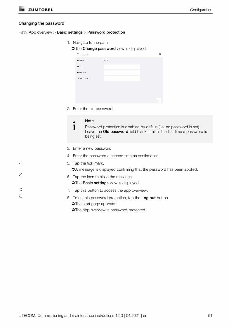
Configuration
LITECOM, Commissioning and maintenance instructions 12.0 | 04.2021 | en 51
Changing the password
Path: App overview > Basic settings > Password protection
1. Navigate to the path.
ÜThe Change password view is displayed.
2. Enter the old password.
iNote
Password protection is disabled by default (i.e. no password is set).Leave the Old password field blank if this is the first time a password isbeing set.
3. Enter a new password.
4. Enter the password a second time as confirmation.
5. Tap the tick mark.
ÜA message is displayed confirming that the password has been applied.
6. Tap the icon to close the message.
ÜThe Basic settings view is displayed.
7. Tap this button to access the app overview.
8. To enable password protection, tap the Log out button.
ÜThe start page appears.
ÜThe app overview is password-protected.
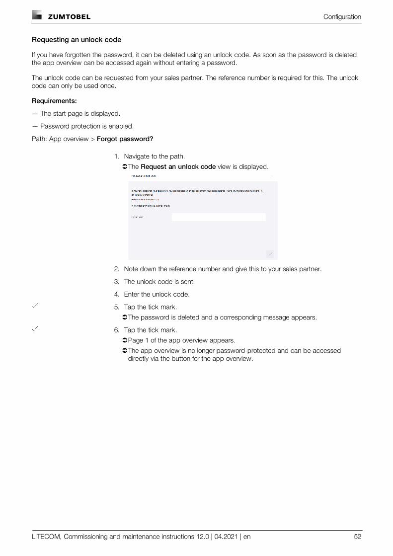
Configuration
LITECOM, Commissioning and maintenance instructions 12.0 | 04.2021 | en 52
Requesting an unlock code
If you have forgotten the password, it can be deleted using an unlock code. As soon as the password is deletedthe app overview can be accessed again without entering a password.
The unlock code can be requested from your sales partner. The reference number is required for this. The unlockcode can only be used once.
Requirements:
— The start page is displayed.
— Password protection is enabled.
Path: App overview > Forgot password?
1. Navigate to the path.
ÜThe Request an unlock code view is displayed.
2. Note down the reference number and give this to your sales partner.
3. The unlock code is sent.
4. Enter the unlock code.
5. Tap the tick mark.
ÜThe password is deleted and a corresponding message appears.
6. Tap the tick mark.
ÜPage 1 of the app overview appears.
ÜThe app overview is no longer password-protected and can be accesseddirectly via the button for the app overview.

Configuration
LITECOM, Commissioning and maintenance instructions 12.0 | 04.2021 | en 53
10.1.2 Geographical coordinates
The LITECOM CCD control device uses geographical coordinates to determine the time of the sunrise and sunsetat that specific location.These times are required in order to configure day/night shows.
Path: App overview > Basic settings > Geo. coordinates
Changing geographical coordinates
Path: App overview > Basic settings > Geo. coordinates
1. Navigate to the path.
ÜThe Set geographical coordinates view is displayed.
2. To select a previously defined location, tap the button in the header and thenselect the desired location.
– or –
2. Set the desired value.
ÜThe times for the sunrise and sunset are updated.
iNote
· Icon for sunrise:
· Icon for sunset:
3. Tap the tick mark.
ÜThe Basic settings view is displayed.
4. Tap this button to access the app overview.
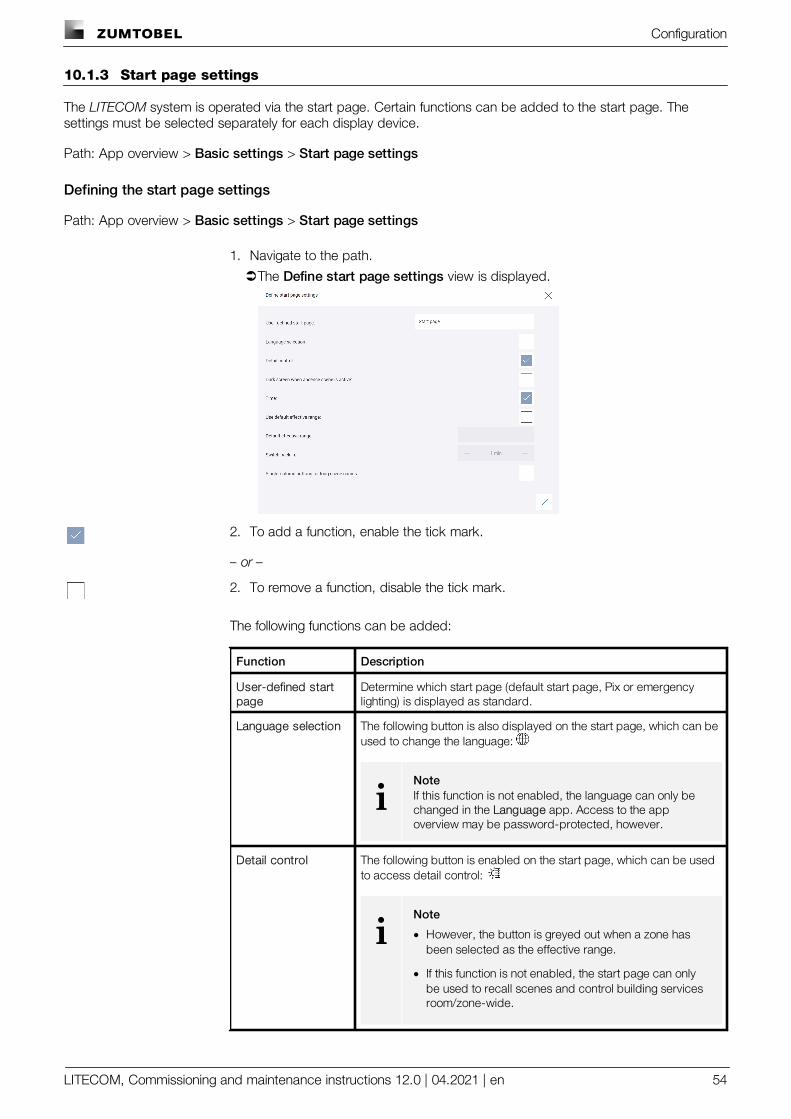
Configuration
LITECOM, Commissioning and maintenance instructions 12.0 | 04.2021 | en 54
10.1.3 Start page settings
The LITECOM system is operated via the start page. Certain functions can be added to the start page. Thesettings must be selected separately for each display device.
Path: App overview > Basic settings > Start page settings
Defining the start page settings
Path: App overview > Basic settings > Start page settings
1. Navigate to the path.
ÜThe Define start page settings view is displayed.
2. To add a function, enable the tick mark.
– or –
2. To remove a function, disable the tick mark.
The following functions can be added:
Function Description
User-defined startpage
Determine which start page (default start page, Pix or emergencylighting) is displayed as standard.
Language selection The following button is also displayed on the start page, which can beused to change the language:
iNoteIf this function is not enabled, the language can only bechanged in the Language app. Access to the appoverview may be password-protected, however.
Detail control The following button is enabled on the start page, which can be usedto access detail control:
iNote
· However, the button is greyed out when a zone hasbeen selected as the effective range.
· If this function is not enabled, the start page can onlybe used to recall scenes and control building servicesroom/zone-wide.
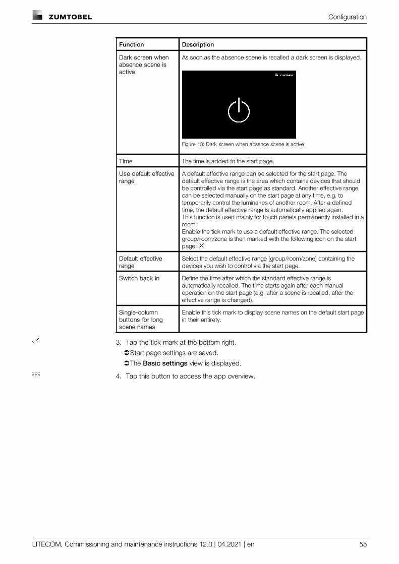
Configuration
LITECOM, Commissioning and maintenance instructions 12.0 | 04.2021 | en 55
Function Description
Dark screen whenabsence scene isactive
As soon as the absence scene is recalled a dark screen is displayed.
Figure 13: Dark screen when absence scene is active
Time The time is added to the start page.
Use default effectiverange
A default effective range can be selected for the start page. Thedefault effective range is the area which contains devices that shouldbe controlled via the start page as standard. Another effective rangecan be selected manually on the start page at any time, e.g. totemporarily control the luminaires of another room. After a definedtime, the default effective range is automatically applied again.This function is used mainly for touch panels permanently installed in aroom.Enable the tick mark to use a default effective range. The selectedgroup/room/zone is then marked with the following icon on the startpage:
Default effectiverange
Select the default effective range (group/room/zone) containing thedevices you wish to control via the start page.
Switch back in Define the time after which the standard effective range isautomatically recalled. The time starts again after each manualoperation on the start page (e.g. after a scene is recalled, after theeffective range is changed).
Single-columnbuttons for longscene names
Enable this tick mark to display scene names on the default start pagein their entirety.
3. Tap the tick mark at the bottom right.
ÜStart page settings are saved.
ÜThe Basic settings view is displayed.
4. Tap this button to access the app overview.
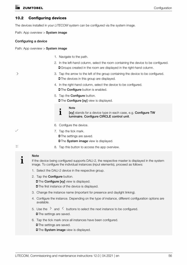
Configuration
LITECOM, Commissioning and maintenance instructions 12.0 | 04.2021 | en 56
10.2 Configuring devices
The devices installed in your LITECOM system can be configured via the system image.
Path: App overview > System image
Configuring a device
Path: App overview > System image
1. Navigate to the path.
2. In the left-hand column, select the room containing the device to be configured.
ÜGroups created in the room are displayed in the right-hand column.
3. Tap the arrow to the left of the group containing the device to be configured.
ÜThe devices in this group are displayed.
4. In the right-hand column, select the device to be configured.
ÜThe Configure button is enabled.
5. Tap the Configure button.
ÜThe Configure [xy] view is displayed.
iNote
[xy] stands for a device type in each case, e.g. Configure TWluminaire, Configure CIRCLE control unit.
6. Configure the device.
7. Tap the tick mark.
ÜThe settings are saved.
ÜThe System image view is displayed.
8. Tap this button to access the app overview.
iNote
If the device being configured supports DALI-2, the respective master is displayed in the systemimage. To configure the individual instances (input elements), proceed as follows:
1. Select the DALI-2 device in the respective group.
2. Tap the Configure button.
ÜThe Configure [xy] view is displayed.
ÜThe first instance of the device is displayed.
3. Change the instance name (important for presence and daylight linking).
4. Configure the instance. Depending on the type of instance, different configuration options areavailable.
5. Use the and buttons to select the next instance to be configured.
ÜThe settings are saved.
6. Tap the tick mark once all instances have been configured.
ÜThe settings are saved.
ÜThe System image view is displayed.
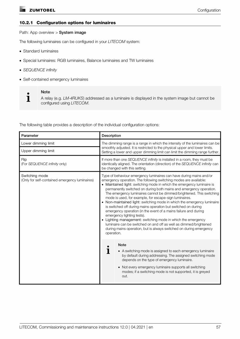
Configuration
LITECOM, Commissioning and maintenance instructions 12.0 | 04.2021 | en 57
10.2.1 Configuration options for luminaires
Path: App overview > System image
The following luminaires can be configured in your LITECOM system:
· Standard luminaires
· Special luminaires: RGB luminaires, Balance luminaires and TW luminaires
· SEQUENCE infinity
· Self-contained emergency luminaires
iNote
A relay (e.g. LM-4RUKS) addressed as a luminaire is displayed in the system image but cannot beconfigured using LITECOM.
The following table provides a description of the individual configuration options:
Parameter Description
Lower dimming limit The dimming range is a range in which the intensity of the luminaires can besmoothly adjusted. It is restricted to the physical upper and lower limits.Setting a lower and upper dimming limit can limit the dimming range further.Upper dimming limit
Flip(For SEQUENCE infinity only)
If more than one SEQUENCE infinity is installed in a room, they must beidentically aligned. The orientation (direction) of the SEQUENCE infinity canbe changed with this setting.
Switching mode(Only for self-contained emergency luminaires)
Type of behaviour emergency luminaires can have during mains and/oremergency operation. The following switching modes are available:· Maintained light: switching mode in which the emergency luminaire is
permanently switched on during both mains and emergency operation.The emergency luminaires cannot be dimmed/brightened. This switchingmode is used, for example, for escape-sign luminaires.
· Non-maintained light: switching mode in which the emergency luminaireis switched off during mains operation but switched on duringemergency operation (in the event of a mains failure and duringemergency lighting tests).
· Lighting management: switching mode in which the emergencyluminaire can be switched on and off as well as dimmed/brightenedduring mains operation, but is always switched on during emergencyoperation.
iNote
· A switching mode is assigned to each emergency luminaireby default during addressing. The assigned switching modedepends on the type of emergency luminaire.
· Not every emergency luminaire supports all switchingmodes; if a switching mode is not supported, it is greyedout.
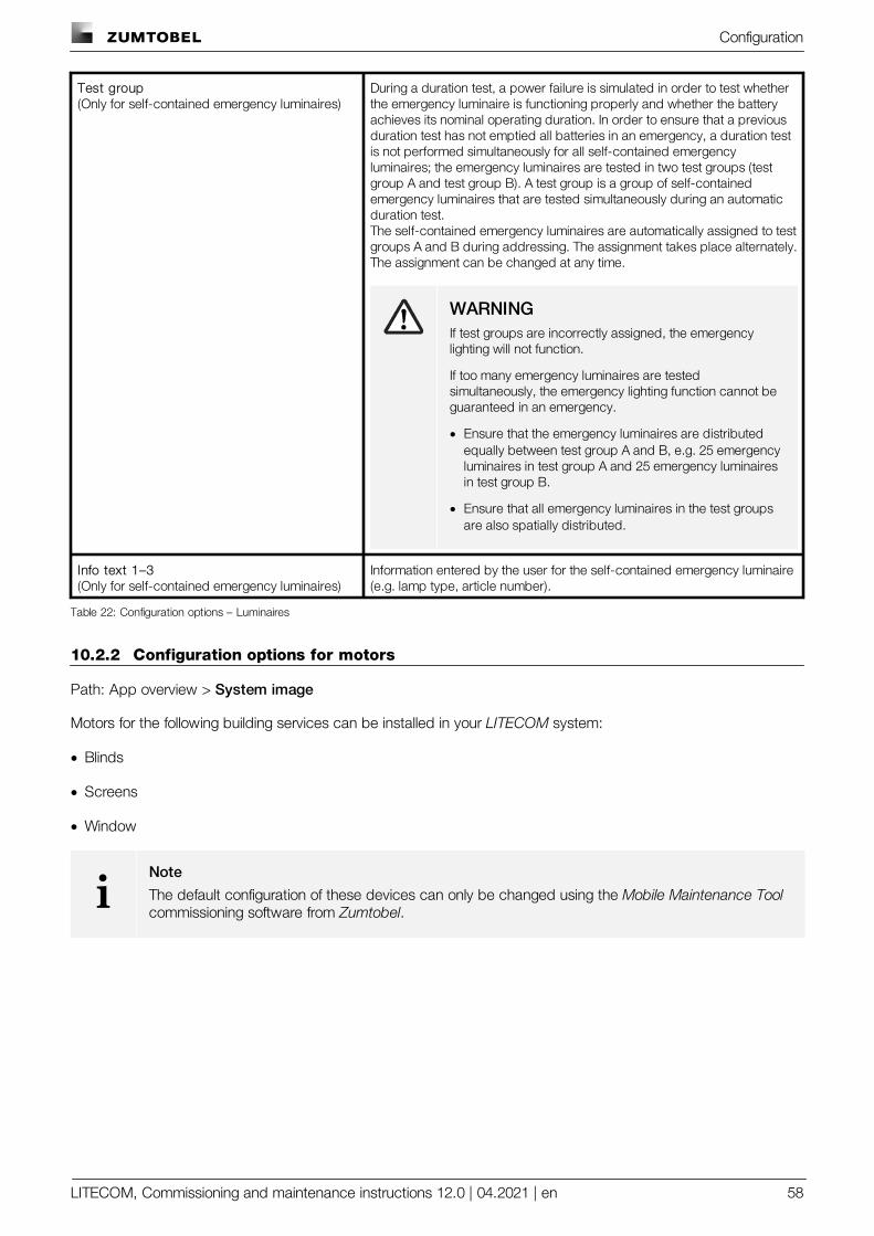
Configuration
LITECOM, Commissioning and maintenance instructions 12.0 | 04.2021 | en 58
Test group(Only for self-contained emergency luminaires)
During a duration test, a power failure is simulated in order to test whetherthe emergency luminaire is functioning properly and whether the batteryachieves its nominal operating duration. In order to ensure that a previousduration test has not emptied all batteries in an emergency, a duration testis not performed simultaneously for all self-contained emergencyluminaires; the emergency luminaires are tested in two test groups (testgroup A and test group B). A test group is a group of self-containedemergency luminaires that are tested simultaneously during an automaticduration test.The self-contained emergency luminaires are automatically assigned to testgroups A and B during addressing. The assignment takes place alternately.The assignment can be changed at any time.
WARNINGIf test groups are incorrectly assigned, the emergencylighting will not function.
If too many emergency luminaires are testedsimultaneously, the emergency lighting function cannot beguaranteed in an emergency.
· Ensure that the emergency luminaires are distributedequally between test group A and B, e.g. 25 emergencyluminaires in test group A and 25 emergency luminairesin test group B.
· Ensure that all emergency luminaires in the test groupsare also spatially distributed.
Info text 1–3(Only for self-contained emergency luminaires)
Information entered by the user for the self-contained emergency luminaire(e.g. lamp type, article number).
Table 22: Configuration options – Luminaires
10.2.2 Configuration options for motors
Path: App overview > System image
Motors for the following building services can be installed in your LITECOM system:
· Blinds
· Screens
· Window
iNote
The default configuration of these devices can only be changed using the Mobile Maintenance Toolcommissioning software from Zumtobel.
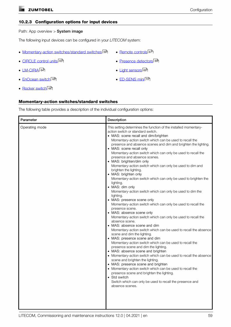
Configuration
LITECOM, Commissioning and maintenance instructions 12.0 | 04.2021 | en 59
10.2.3 Configuration options for input devices
Path: App overview > System image
The following input devices can be configured in your LITECOM system:
· Momentary-action switches/standard switches
· CIRCLE control units
· LM-CIRIA
· EnOcean switch
· Rocker switch
· Remote controls
· Presence detectors
· Light sensors
· ED-SENS mini
Momentary-action switches/standard switches
The following table provides a description of the individual configuration options:
Parameter Description
Operating mode This setting determines the function of the installed momentary-action switch or standard switch.· MAS: scene recall and dim/brighten
Momentary-action switch which can be used to recall thepresence and absence scenes and dim and brighten the lighting.
· MAS: scene recall onlyMomentary-action switch which can only be used to recall thepresence and absence scenes.
· MAS: brighten/dim onlyMomentary-action switch which can only be used to dim andbrighten the lighting.
· MAS: brighten onlyMomentary-action switch which can only be used to brighten thelighting.
· MAS: dim onlyMomentary-action switch which can only be used to dim thelighting.
· MAS: presence scene onlyMomentary-action switch which can only be used to recall thepresence scene.
· MAS: absence scene onlyMomentary-action switch which can only be used to recall theabsence scene.
· MAS: absence scene and dimMomentary-action switch which can be used to recall the absencescene and dim the lighting.
· MAS: presence scene and dimMomentary-action switch which can be used to recall thepresence scene and dim the lighting.
· MAS: absence scene and brighten· Momentary-action switch which can be used to recall the absence
scene and brighten the lighting.· MAS: presence scene and brighten· Momentary-action switch which can be used to recall the
presence scene and brighten the lighting.· Std switch
Switch which can only be used to recall the presence andabsence scenes.
59
63
64
65
66
67
69
69
70
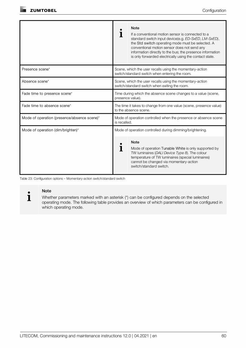
Configuration
LITECOM, Commissioning and maintenance instructions 12.0 | 04.2021 | en 60
iNote
If a conventional motion sensor is connected to astandard switch input device(e.g. ED-SxED, LM-SxED),the Std switch operating mode must be selected. Aconventional motion sensor does not send anyinformation directly to the bus; the presence informationis only forwarded electrically using the contact state.
Presence scene* Scene, which the user recalls using the momentary-actionswitch/standard switch when entering the room.
Absence scene* Scene, which the user recalls using the momentary-actionswitch/standard switch when exiting the room.
Fade time to presence scene* Time during which the absence scene changes to a value (scene,presence value).
Fade time to absence scene* The time it takes to change from one value (scene, presence value)to the absence scene.
Mode of operation (presence/absence scene)* Mode of operation controlled when the presence or absence sceneis recalled.
Mode of operation (dim/brighten)* Mode of operation controlled during dimming/brightening.
iNote
Mode of operation Tunable White is only supported byTW luminaires (DALI Device Type 8). The colourtemperature of TW luminaires (special luminaires)cannot be changed via momentary-actionswitch/standard switch.
Table 23: Configuration options – Momentary-action switch/standard switch
iNote
Whether parameters marked with an asterisk (*) can be configured depends on the selectedoperating mode. The following table provides an overview of which parameters can be configured inwhich operating mode.
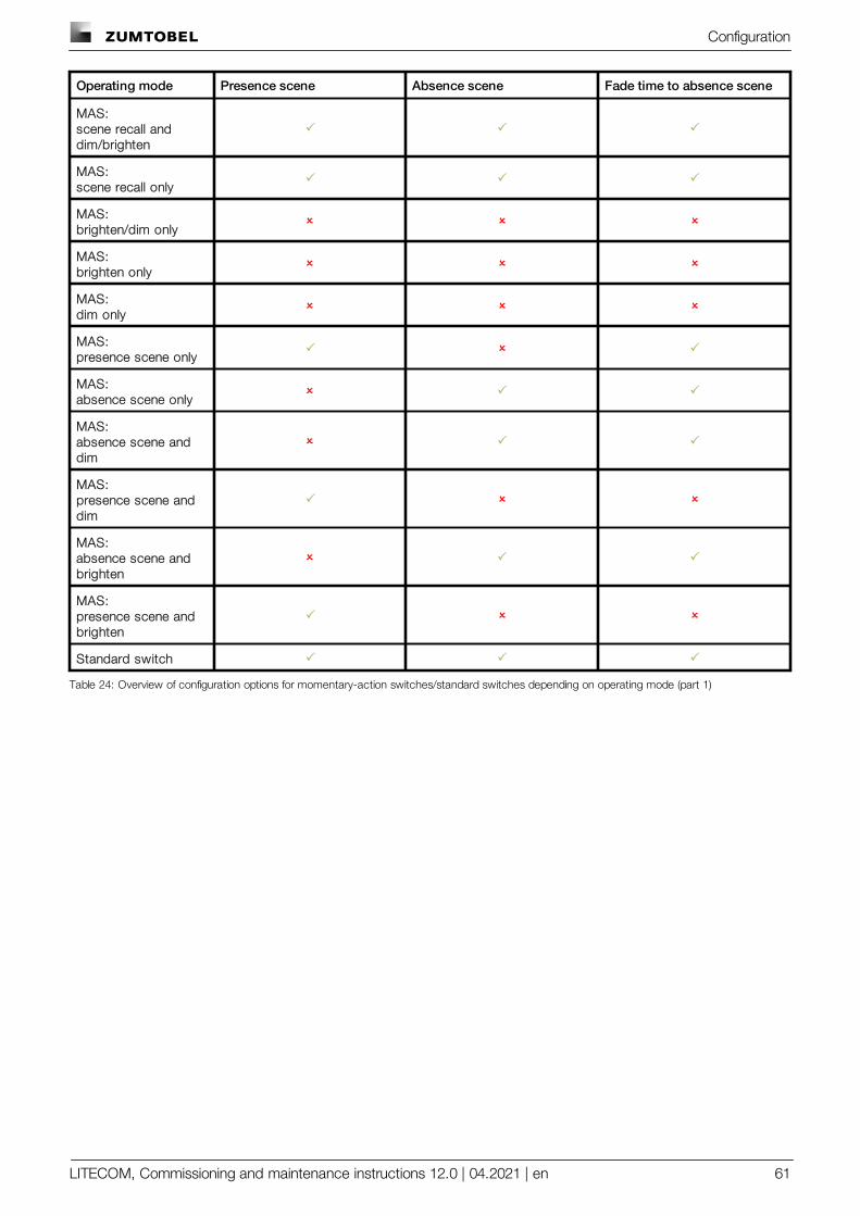
Configuration
LITECOM, Commissioning and maintenance instructions 12.0 | 04.2021 | en 61
Operating mode Presence scene Absence scene Fade time to absence scene
MAS: scene recall anddim/brighten
P P P
MAS:scene recall only
P P P
MAS:brighten/dim only
O O O
MAS:brighten only
O O O
MAS:dim only
O O O
MAS:presence scene only
P O P
MAS:absence scene only
O P P
MAS:absence scene anddim
O P P
MAS:presence scene anddim
P O O
MAS:absence scene andbrighten
O P P
MAS:presence scene andbrighten
P O O
Standard switch P P P
Table 24: Overview of configuration options for momentary-action switches/standard switches depending on operating mode (part 1)
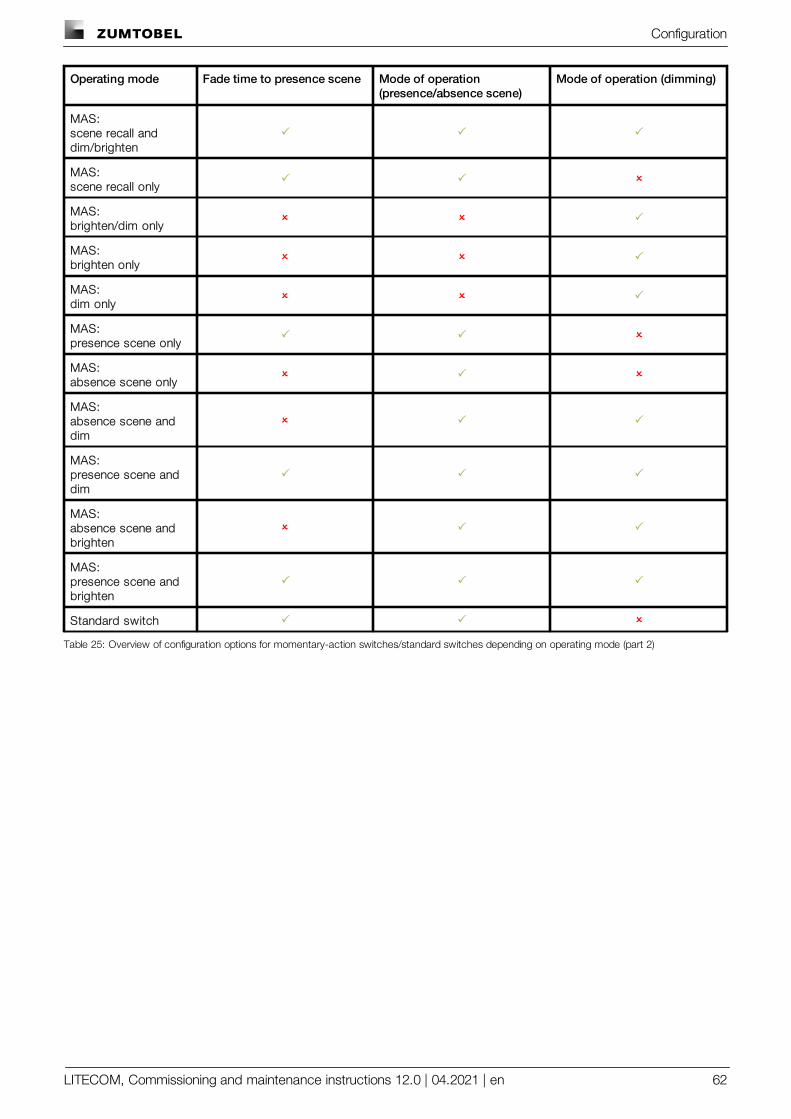
Configuration
LITECOM, Commissioning and maintenance instructions 12.0 | 04.2021 | en 62
Operating mode Fade time to presence scene Mode of operation(presence/absence scene)
Mode of operation (dimming)
MAS: scene recall anddim/brighten
P P P
MAS:scene recall only
P P O
MAS:brighten/dim only
O O P
MAS:brighten only
O O P
MAS:dim only
O O P
MAS:presence scene only
P P O
MAS:absence scene only
O P O
MAS:absence scene anddim
O P P
MAS:presence scene anddim
P P P
MAS:absence scene andbrighten
O P P
MAS:presence scene andbrighten
P P P
Standard switch P P O
Table 25: Overview of configuration options for momentary-action switches/standard switches depending on operating mode (part 2)
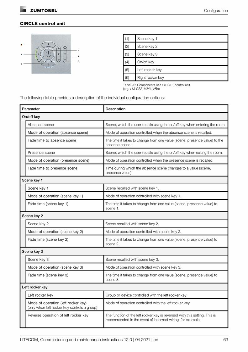
Configuration
LITECOM, Commissioning and maintenance instructions 12.0 | 04.2021 | en 63
CIRCLE control unit
(1) Scene key 1
(2) Scene key 2
(3) Scene key 3
(4) On/off key
(5) Left rocker key
(6) Right rocker key
Table 26: Components of a CIRCLE control unit(e.g. LM-CSS 1/2/3 Li/Be)
The following table provides a description of the individual configuration options:
Parameter Description
On/off key
Absence scene Scene, which the user recalls using the on/off key when entering the room.
Mode of operation (absence scene) Mode of operation controlled when the absence scene is recalled.
Fade time to absence scene The time it takes to change from one value (scene, presence value) to theabsence scene.
Presence scene Scene, which the user recalls using the on/off key when exiting the room.
Mode of operation (presence scene) Mode of operation controlled when the presence scene is recalled.
Fade time to presence scene Time during which the absence scene changes to a value (scene,presence value).
Scene key 1
Scene key 1 Scene recalled with scene key 1.
Mode of operation (scene key 1) Mode of operation controlled with scene key 1.
Fade time (scene key 1) The time it takes to change from one value (scene, presence value) toscene 1.
Scene key 2
Scene key 2 Scene recalled with scene key 2.
Mode of operation (scene key 2) Mode of operation controlled with scene key 2.
Fade time (scene key 2) The time it takes to change from one value (scene, presence value) toscene 2.
Scene key 3
Scene key 3 Scene recalled with scene key 3.
Mode of operation (scene key 3) Mode of operation controlled with scene key 3.
Fade time (scene key 3) The time it takes to change from one value (scene, presence value) toscene 3.
Left rocker key
Left rocker key Group or device controlled with the left rocker key.
Mode of operation (left rocker key)(only when left rocker key controls a group)
Mode of operation controlled with the left rocker key.
Reverse operation of left rocker key The function of the left rocker key is reversed with this setting. This isrecommended in the event of incorrect wiring, for example.
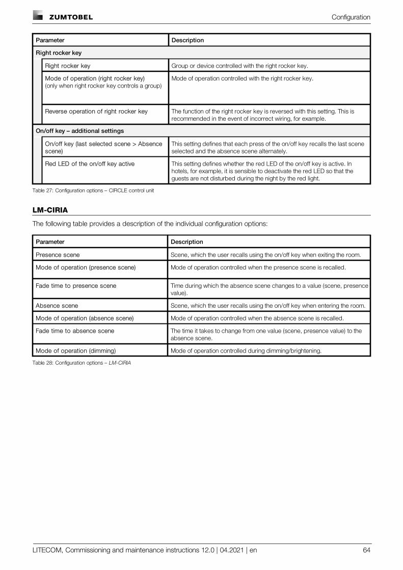
Configuration
LITECOM, Commissioning and maintenance instructions 12.0 | 04.2021 | en 64
Parameter Description
Right rocker key
Right rocker key Group or device controlled with the right rocker key.
Mode of operation (right rocker key)(only when right rocker key controls a group)
Mode of operation controlled with the right rocker key.
Reverse operation of right rocker key The function of the right rocker key is reversed with this setting. This isrecommended in the event of incorrect wiring, for example.
On/off key – additional settings
On/off key (last selected scene > Absencescene)
This setting defines that each press of the on/off key recalls the last sceneselected and the absence scene alternately.
Red LED of the on/off key active This setting defines whether the red LED of the on/off key is active. Inhotels, for example, it is sensible to deactivate the red LED so that theguests are not disturbed during the night by the red light.
Table 27: Configuration options – CIRCLE control unit
LM-CIRIA
The following table provides a description of the individual configuration options:
Parameter Description
Presence scene Scene, which the user recalls using the on/off key when exiting the room.
Mode of operation (presence scene) Mode of operation controlled when the presence scene is recalled.
Fade time to presence scene Time during which the absence scene changes to a value (scene, presencevalue).
Absence scene Scene, which the user recalls using the on/off key when entering the room.
Mode of operation (absence scene) Mode of operation controlled when the absence scene is recalled.
Fade time to absence scene The time it takes to change from one value (scene, presence value) to theabsence scene.
Mode of operation (dimming) Mode of operation controlled during dimming/brightening.
Table 28: Configuration options – LM-CIRIA
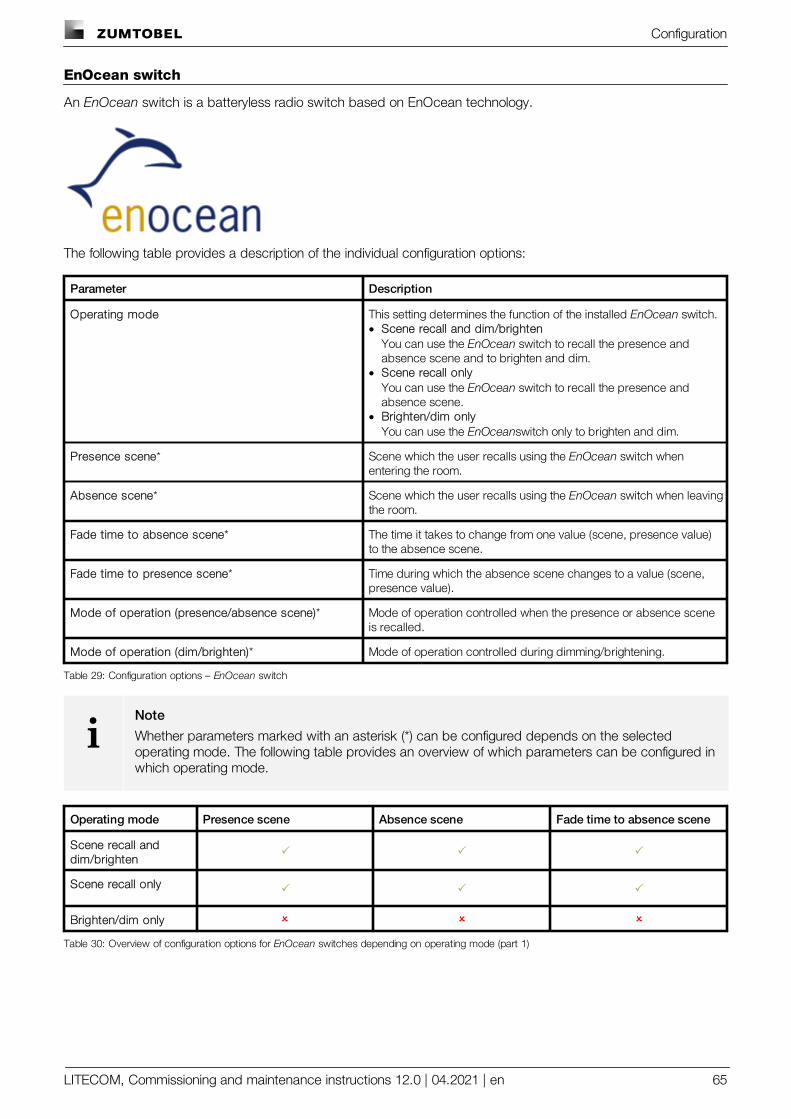
Configuration
LITECOM, Commissioning and maintenance instructions 12.0 | 04.2021 | en 65
EnOcean switch
An EnOcean switch is a batteryless radio switch based on EnOcean technology.
The following table provides a description of the individual configuration options:
Parameter Description
Operating mode This setting determines the function of the installed EnOcean switch.· Scene recall and dim/brighten
You can use the EnOcean switch to recall the presence andabsence scene and to brighten and dim.
· Scene recall onlyYou can use the EnOcean switch to recall the presence andabsence scene.
· Brighten/dim onlyYou can use the EnOceanswitch only to brighten and dim.
Presence scene* Scene which the user recalls using the EnOcean switch whenentering the room.
Absence scene* Scene which the user recalls using the EnOcean switch when leavingthe room.
Fade time to absence scene* The time it takes to change from one value (scene, presence value)to the absence scene.
Fade time to presence scene* Time during which the absence scene changes to a value (scene,presence value).
Mode of operation (presence/absence scene)* Mode of operation controlled when the presence or absence sceneis recalled.
Mode of operation (dim/brighten)* Mode of operation controlled during dimming/brightening.
Table 29: Configuration options – EnOcean switch
iNote
Whether parameters marked with an asterisk (*) can be configured depends on the selectedoperating mode. The following table provides an overview of which parameters can be configured inwhich operating mode.
Operating mode Presence scene Absence scene Fade time to absence scene
Scene recall anddim/brighten
P P P
Scene recall only P P P
Brighten/dim only O O O
Table 30: Overview of configuration options for EnOcean switches depending on operating mode (part 1)
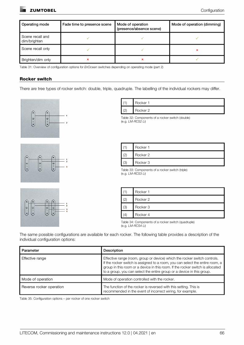
Configuration
LITECOM, Commissioning and maintenance instructions 12.0 | 04.2021 | en 66
Operating mode Fade time to presence scene Mode of operation(presence/absence scene)
Mode of operation (dimming)
Scene recall anddim/brighten
P P P
Scene recall only P P O
Brighten/dim only O O P
Table 31: Overview of configuration options for EnOcean switches depending on operating mode (part 2)
Rocker switch
There are tree types of rocker switch: double, triple, quadruple. The labelling of the individual rockers may differ.
(1) Rocker 1
(2) Rocker 2
Table 32: Components of a rocker switch (double)(e.g. LM-RCS2 Li)
(1) Rocker 1
(2) Rocker 2
(3) Rocker 3
Table 33: Components of a rocker switch (triple)(e.g. LM-RCS3 Li)
(1) Rocker 1
(2) Rocker 2
(3) Rocker 3
(4) Rocker 4
Table 34: Components of a rocker switch (quadruple)(e.g. LM-RCS4 Li)
The same possible configurations are available for each rocker. The following table provides a description of theindividual configuration options:
Parameter Description
Effective range Effective range (room, group or device) which the rocker switch controls.If the rocker switch is assigned to a room, you can select the entire room, agroup in this room or a device in this room. If the rocker switch is allocatedto a group, you can select the entire group or a device in this group.
Mode of operation Mode of operation controlled with the rocker.
Reverse rocker operation The function of the rocker is reversed with this setting. This isrecommended in the event of incorrect wiring, for example.
Table 35: Configuration options – per rocker of one rocker switch
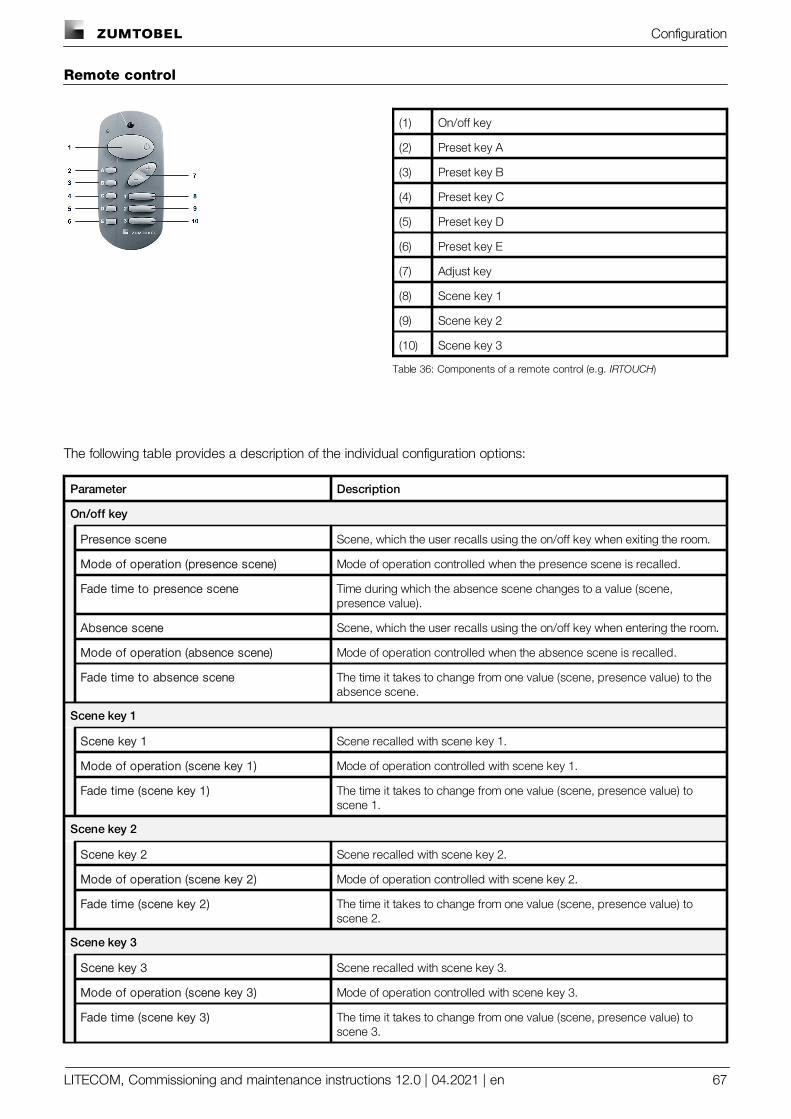
Configuration
LITECOM, Commissioning and maintenance instructions 12.0 | 04.2021 | en 67
Remote control
(1) On/off key
(2) Preset key A
(3) Preset key B
(4) Preset key C
(5) Preset key D
(6) Preset key E
(7) Adjust key
(8) Scene key 1
(9) Scene key 2
(10) Scene key 3
Table 36: Components of a remote control (e.g. IRTOUCH)
The following table provides a description of the individual configuration options:
Parameter Description
On/off key
Presence scene Scene, which the user recalls using the on/off key when exiting the room.
Mode of operation (presence scene) Mode of operation controlled when the presence scene is recalled.
Fade time to presence scene Time during which the absence scene changes to a value (scene,presence value).
Absence scene Scene, which the user recalls using the on/off key when entering the room.
Mode of operation (absence scene) Mode of operation controlled when the absence scene is recalled.
Fade time to absence scene The time it takes to change from one value (scene, presence value) to theabsence scene.
Scene key 1
Scene key 1 Scene recalled with scene key 1.
Mode of operation (scene key 1) Mode of operation controlled with scene key 1.
Fade time (scene key 1) The time it takes to change from one value (scene, presence value) toscene 1.
Scene key 2
Scene key 2 Scene recalled with scene key 2.
Mode of operation (scene key 2) Mode of operation controlled with scene key 2.
Fade time (scene key 2) The time it takes to change from one value (scene, presence value) toscene 2.
Scene key 3
Scene key 3 Scene recalled with scene key 3.
Mode of operation (scene key 3) Mode of operation controlled with scene key 3.
Fade time (scene key 3) The time it takes to change from one value (scene, presence value) toscene 3.
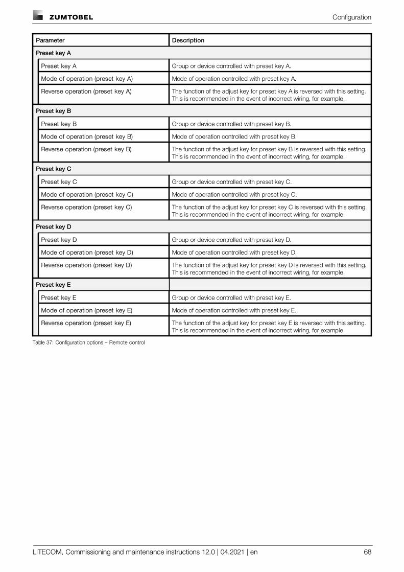
Configuration
LITECOM, Commissioning and maintenance instructions 12.0 | 04.2021 | en 68
Parameter Description
Preset key A
Preset key A Group or device controlled with preset key A.
Mode of operation (preset key A) Mode of operation controlled with preset key A.
Reverse operation (preset key A) The function of the adjust key for preset key A is reversed with this setting.This is recommended in the event of incorrect wiring, for example.
Preset key B
Preset key B Group or device controlled with preset key B.
Mode of operation (preset key B) Mode of operation controlled with preset key B.
Reverse operation (preset key B) The function of the adjust key for preset key B is reversed with this setting.This is recommended in the event of incorrect wiring, for example.
Preset key C
Preset key C Group or device controlled with preset key C.
Mode of operation (preset key C) Mode of operation controlled with preset key C.
Reverse operation (preset key C) The function of the adjust key for preset key C is reversed with this setting.This is recommended in the event of incorrect wiring, for example.
Preset key D
Preset key D Group or device controlled with preset key D.
Mode of operation (preset key D) Mode of operation controlled with preset key D.
Reverse operation (preset key D) The function of the adjust key for preset key D is reversed with this setting.This is recommended in the event of incorrect wiring, for example.
Preset key E
Preset key E Group or device controlled with preset key E.
Mode of operation (preset key E) Mode of operation controlled with preset key E.
Reverse operation (preset key E) The function of the adjust key for preset key E is reversed with this setting.This is recommended in the event of incorrect wiring, for example.
Table 37: Configuration options – Remote control
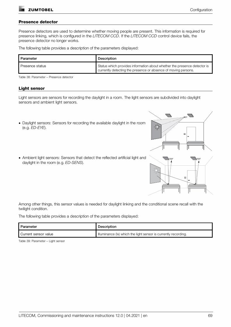
Configuration
LITECOM, Commissioning and maintenance instructions 12.0 | 04.2021 | en 69
Presence detector
Presence detectors are used to determine whether moving people are present. This information is required forpresence linking, which is configured in the LITECOM CCD. If the LITECOM CCD control device fails, thepresence detector no longer works.
The following table provides a description of the parameters displayed:
Parameter Description
Presence status Status which provides information about whether the presence detector iscurrently detecting the presence or absence of moving persons.
Table 38: Parameter – Presence detector
Light sensor
Light sensors are sensors for recording the daylight in a room. The light sensors are subdivided into daylightsensors and ambient light sensors.
· Daylight sensors: Sensors for recording the available daylight in the room(e.g. ED-EYE).
· Ambient light sensors: Sensors that detect the reflected artificial light anddaylight in the room (e.g. ED-SENS).
Among other things, this sensor values is needed for daylight linking and the conditional scene recall with thetwilight condition.
The following table provides a description of the parameters displayed:
Parameter Description
Current sensor value Illuminance (lx) which the light sensor is currently recording.
Table 39: Parameter – Light sensor
Configuration
LITECOM, Commissioning and maintenance instructions 12.0 | 04.2021 | en 70
ED-SENS mini
The ED-SENS mini is a multi-function sensor for presence and light detection.
Although the ED-SENS mini multi-function sensor is only one physical device, it appears twice in the systemimage:
1 x for presence detection
1 x for light detection
For this reason, both a presence detector and a light sensor must be configured in the system image.
Presence detection
The presence or absence of moving persons is determined via the presence detection. This information is requiredfor presence linking, which is configured in the LITECOM CCD control device. If the LITECOM CCD fails, thepresence detector no longer works.
The following table provides a description of the parameters displayed:
Parameter Description
Presence status Status which indicates whether the presence detector is currently detectingthe presence or absence of moving persons.
Table 40: Parameter – presence detection
Light detection
The light detection detects the available daylight in the room. This information is needed, inter alia, for the daylightlinking and for the conditional scene recall with the condition "twilight".
The following table provides a description of the parameters and functions which are displayed:
Parameter Description
Measured illuminance Reference value for calibrating the light sensor. Measure the referencevalue with a luxmeter beneath the sensor and enter this value in the field. LITECOM uses this reference value for daylight linking, among other things.
Calibrate Procedure in which the reference value is stored which is subsequentlyused for various functions (for daylight linking and the conditional scenerecall with the twilight condition, among other things).
Current sensor value (uncalibrated) Illuminance (lx) which the uncalibrated light sensor is currently recording.
Current sensor value (calibrated) Illuminance (lx) which the calibrated light sensor is currently recording.
Algorithm for daylight linking Indicates the algorithm currently used for ambient light sensors.
Table 41: Parameters and functions – light detection
Configuration
LITECOM, Commissioning and maintenance instructions 12.0 | 04.2021 | en 71
10.2.4 Configuration options for signalling contacts
A signalling contact is a contact that is used to forward status information. The signalling contact is opened orclosed if the status changes.
Path: App overview > System image
The following signalling contacts can be installed in your LITECOM system:
· Signalling contacts: e.g. LM-4RUKS
iNote
The default configuration of these devices can only be changed using the Mobile Maintenance Toolcommissioning software from Zumtobel.
· Remote display: ONLITE BRI
The following table provides a description of the individual configuration options:
Parameter Description
Info text 1–3 Information entered by the user for ONLITE BRI (e.g. installation location,article number).
Table 42: Configuration options – ONLITE BRI
10.2.5 Configuration options for DALI-2 devices
The following table provides a description of the parameters:
Parameter Description
Instance name The name of the instance, entered by the user.
Effective range The effective range to which the instance has been assigned.· Switch/remote control: if a new effective range is selected for switches or
remote controls, the corresponding switch/remote control is also displayed in the new area (room, group or zone) in the system image.
· Light sensor: o Shows the effective range assigned to the sensor in the Daylight linking
app.o If the sensor is used for the conditional scene recall with the twilight
condition, the effective range in which the condition is active is also displayed.
· Presence detector: shows the effective range assigned to the sensor in the Presence linking app.
Table 43:Configuration options – DALI-2 devices
iNote
The individual configuration options for the instances can be found in the relevant sections coveringconfiguration options for input devices.For more information see Section Configuration options: input devices 59
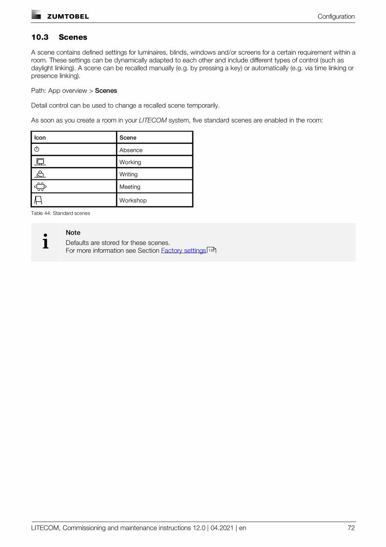
Configuration
LITECOM, Commissioning and maintenance instructions 12.0 | 04.2021 | en 72
10.3 Scenes
A scene contains defined settings for luminaires, blinds, windows and/or screens for a certain requirement within aroom. These settings can be dynamically adapted to each other and include different types of control (such asdaylight linking). A scene can be recalled manually (e.g. by pressing a key) or automatically (e.g. via time linking orpresence linking).
Path: App overview > Scenes
Detail control can be used to change a recalled scene temporarily.
As soon as you create a room in your LITECOM system, five standard scenes are enabled in the room:
Icon Scene
Absence
Working
Writing
Meeting
Workshop
Table 44: Standard scenes
iNote
Defaults are stored for these scenes.For more information see Section Factory settings 135
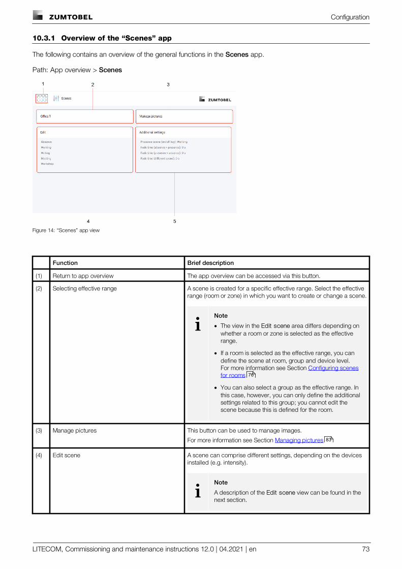
Configuration
LITECOM, Commissioning and maintenance instructions 12.0 | 04.2021 | en 73
10.3.1 Overview of the “Scenes” app
The following contains an overview of the general functions in the Scenes app.
Path: App overview > Scenes
Figure 14: “Scenes” app view
Function Brief description
(1) Return to app overview The app overview can be accessed via this button.
(2) Selecting effective range A scene is created for a specific effective range. Select the effectiverange (room or zone) in which you want to create or change a scene.
iNote
· The view in the Edit scene area differs depending onwhether a room or zone is selected as the effectiverange.
· If a room is selected as the effective range, you candefine the scene at room, group and device level.For more information see Section Configuring scenesfor rooms
· You can also select a group as the effective range. Inthis case, however, you can only define the additionalsettings related to this group; you cannot edit thescene because this is defined for the room.
(3) Manage pictures This button can be used to manage images.
For more information see Section Managing pictures
(4) Edit scene A scene can comprise different settings, depending on the devicesinstalled (e.g. intensity).
iNote
A description of the Edit scene view can be found in thenext section.
76
83
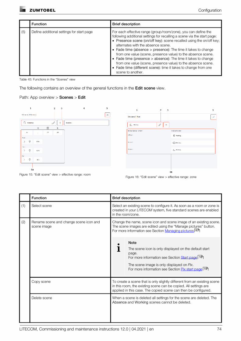
Configuration
LITECOM, Commissioning and maintenance instructions 12.0 | 04.2021 | en 74
Function Brief description
(5) Define additional settings for start page For each effective range (group/room/zone), you can define thefollowing additional settings for recalling a scene via the start page:· Presence scene (on/off key): scene recalled using the on/off key;
alternates with the absence scene.· Fade time (absence > presence): The time it takes to change
from one value (scene, presence value) to the absence scene.· Fade time (presence > absence): The time it takes to change
from one value (scene, presence value) to the absence scene.· Fade time (different scene): time it takes to change from one
scene to another.
Table 45: Functions in the “Scenes” view
The following contains an overview of the general functions in the Edit scene view.
Path: App overview > Scenes > Edit
Figure 15: “Edit scene” view > effective range: roomFigure 16: “Edit scene” view > effective range: zone
Function Brief description
(1) Select scene Select an existing scene to configure it. As soon as a room or zone iscreated in your LITECOM system, five standard scenes are enabledin the room/zone.
(2) Rename scene and change scene icon andscene image
Change the name, scene icon and scene image of an existing scene.The scene images are edited using the “Manage pictures” button.For more information see Section Managing pictures
iNote
The scene icon is only displayed on the default startpage.For more information see Section Start page
The scene image is only displayed on Pix.For more information see Section Pix start page
Copy scene To create a scene that is only slightly different from an existing scenein this room, the existing scene can be copied. All settings areapplied in this case. The copied scene can then be configured.
Delete scene When a scene is deleted all settings for the scene are deleted. The Absence and Working scenes cannot be deleted.
83
16
19
Configuration
LITECOM, Commissioning and maintenance instructions 12.0 | 04.2021 | en 75
Function Brief description
iNote
Deleting a scene affects functions that use this scene intheir configuration (e.g. conditional scene recall,presence linking). For this reason, check whetherexisting functions will be affected after a scene isdeleted.
(3) Create new scene In addition to the five standard scenes, 16 extra scenes can becreated. When creating a scene, select a name and a scene icon.
iNote
If SEQUENCE infinity are installed in your system, only16 scenes in total can be created.
(4) Select show If you have created a show in the Shows app, you can set it here.There is no show set by default.
iNote
For more information see Shows manual
(5) Save settings As soon as you tap the cross, the changes are saved and the appoverview is displayed.
(6) Configure scene A scene can comprise different settings, depending on the devicesinstalled (e.g. intensity).
iNote· A description of the different icons can be found in
Section Icons .
· You can configure scenes for rooms.For more information see Section Configuring scenesfor rooms
· You can configure scenes for zones.For more information see Section Configuring scenesfor zones
· You can assign daylight linking to the scene.For more information see Daylight linking manual
· You can assign a show to the scene.For more information see Shows manual
Table 46: Functions of the “Edit scene” view
136
76
82
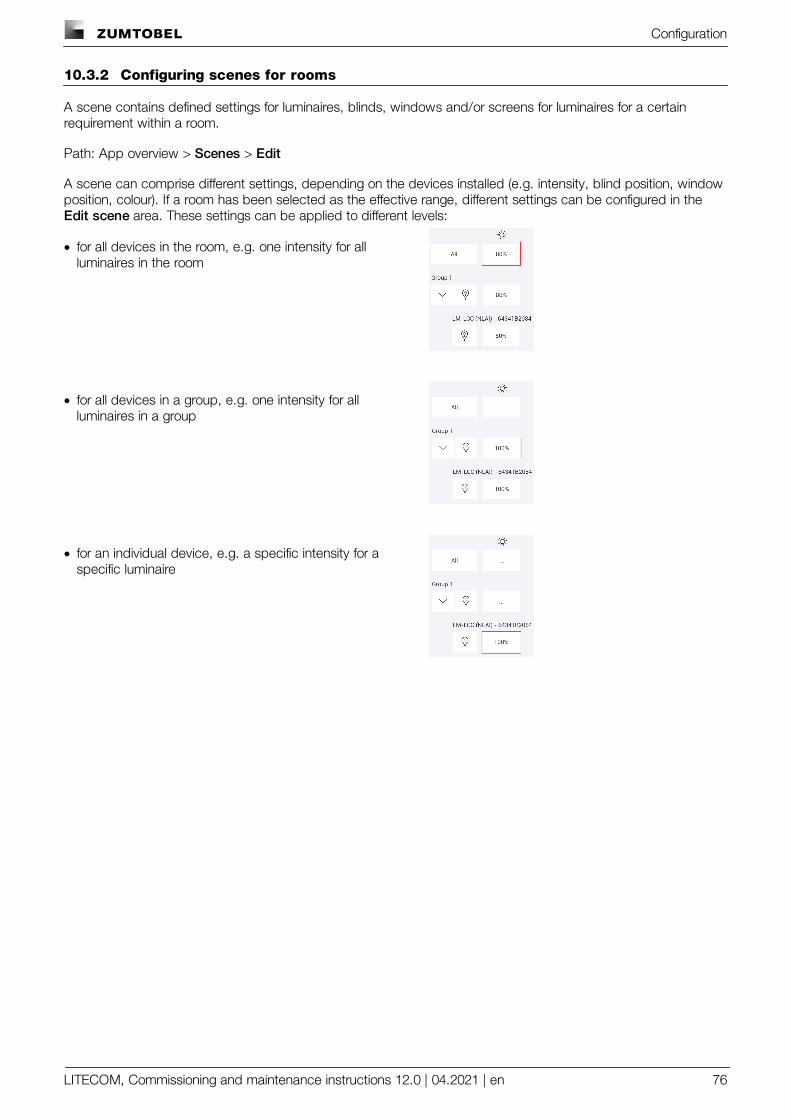
Configuration
LITECOM, Commissioning and maintenance instructions 12.0 | 04.2021 | en 76
10.3.2 Configuring scenes for rooms
A scene contains defined settings for luminaires, blinds, windows and/or screens for luminaires for a certainrequirement within a room.
Path: App overview > Scenes > Edit
A scene can comprise different settings, depending on the devices installed (e.g. intensity, blind position, windowposition, colour). If a room has been selected as the effective range, different settings can be configured in the Edit scene area. These settings can be applied to different levels:
· for all devices in the room, e.g. one intensity for allluminaires in the room
· for all devices in a group, e.g. one intensity for allluminaires in a group
· for an individual device, e.g. a specific intensity for aspecific luminaire
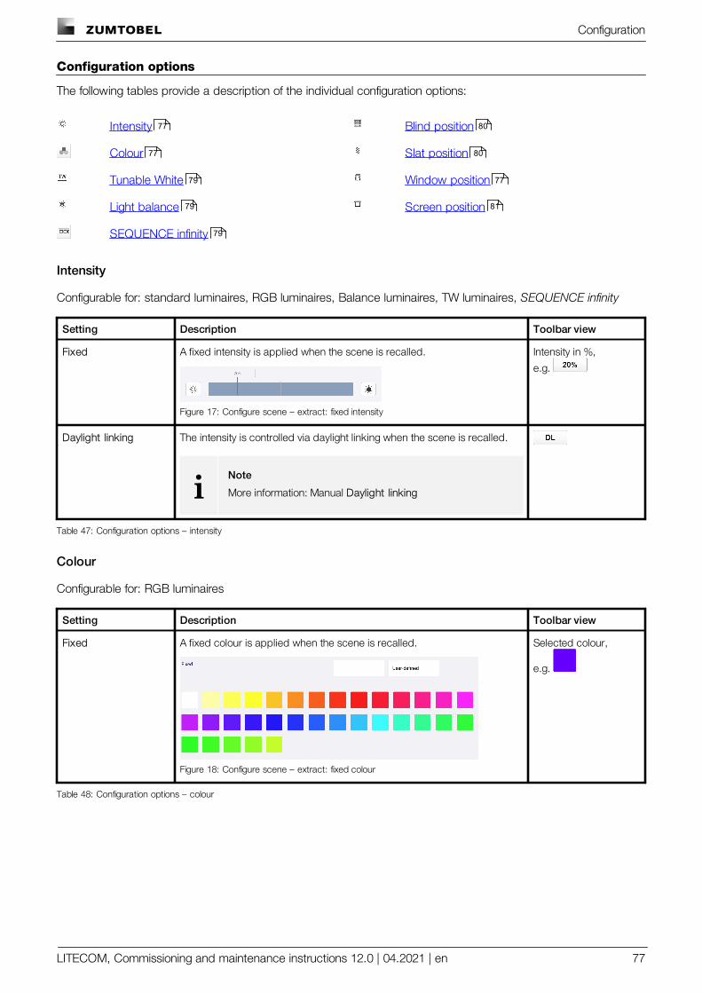
Configuration
LITECOM, Commissioning and maintenance instructions 12.0 | 04.2021 | en 77
Configuration options
The following tables provide a description of the individual configuration options:
Intensity Blind position
Colour Slat position
Tunable White Window position
Light balance Screen position
SEQUENCE infinity
Intensity
Configurable for: standard luminaires, RGB luminaires, Balance luminaires, TW luminaires, SEQUENCE infinity
Setting Description Toolbar view
Fixed A fixed intensity is applied when the scene is recalled.
Figure 17: Configure scene – extract: fixed intensity
Intensity in %,
e.g.
Daylight linking The intensity is controlled via daylight linking when the scene is recalled.
iNote
More information: Manual Daylight linking
Table 47: Configuration options – intensity
Colour
Configurable for: RGB luminaires
Setting Description Toolbar view
Fixed A fixed colour is applied when the scene is recalled.
Figure 18: Configure scene – extract: fixed colour
Selected colour,
e.g.
Table 48: Configuration options – colour
77 80
77 80
79 77
79 81
79
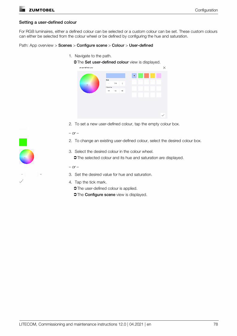
Configuration
LITECOM, Commissioning and maintenance instructions 12.0 | 04.2021 | en 78
Setting a user-defined colour
For RGB luminaires, either a defined colour can be selected or a custom colour can be set. These custom colourscan either be selected from the colour wheel or be defined by configuring the hue and saturation.
Path: App overview > Scenes > Configure scene > Colour > User-defined
1. Navigate to the path.
ÜThe Set user-defined colour view is displayed.
2. To set a new user-defined colour, tap the empty colour box.
– or –
2. To change an existing user-defined colour, select the desired colour box.
3. Select the desired colour in the colour wheel.
ÜThe selected colour and its hue and saturation are displayed.
– or –
3. Set the desired value for hue and saturation.
4. Tap the tick mark.
ÜThe user-defined colour is applied.
ÜThe Configure scene view is displayed.
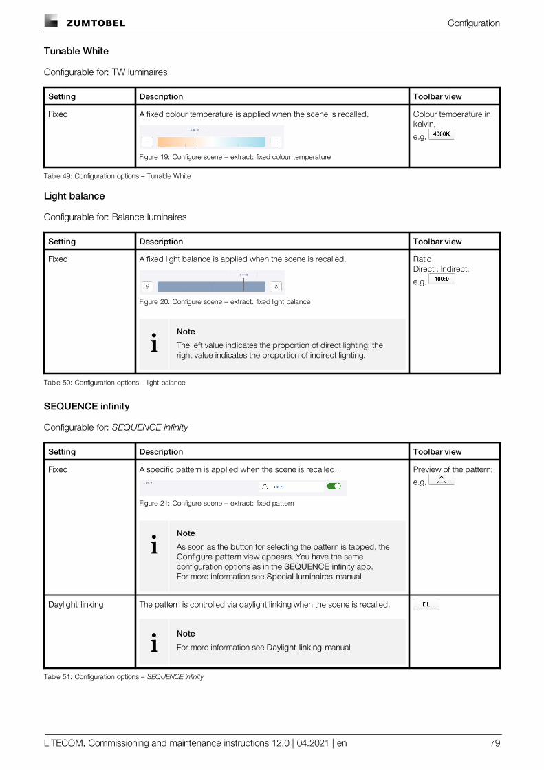
Configuration
LITECOM, Commissioning and maintenance instructions 12.0 | 04.2021 | en 79
Tunable White
Configurable for: TW luminaires
Setting Description Toolbar view
Fixed A fixed colour temperature is applied when the scene is recalled.
Figure 19: Configure scene – extract: fixed colour temperature
Colour temperature inkelvin,
e.g.
Table 49: Configuration options – Tunable White
Light balance
Configurable for: Balance luminaires
Setting Description Toolbar view
Fixed A fixed light balance is applied when the scene is recalled.
Figure 20: Configure scene – extract: fixed light balance
iNote
The left value indicates the proportion of direct lighting; theright value indicates the proportion of indirect lighting.
RatioDirect : Indirect;
e.g.
Table 50: Configuration options – light balance
SEQUENCE infinity
Configurable for: SEQUENCE infinity
Setting Description Toolbar view
Fixed A specific pattern is applied when the scene is recalled.
Figure 21: Configure scene – extract: fixed pattern
iNote
As soon as the button for selecting the pattern is tapped, the Configure pattern view appears. You have the sameconfiguration options as in the SEQUENCE infinity app.For more information see Special luminaires manual
Preview of the pattern;
e.g.
Daylight linking The pattern is controlled via daylight linking when the scene is recalled.
iNote
For more information see Daylight linking manual
Table 51: Configuration options – SEQUENCE infinity
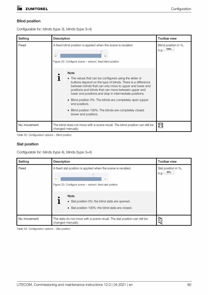
Configuration
LITECOM, Commissioning and maintenance instructions 12.0 | 04.2021 | en 80
Blind position
Configurable for: blinds (type 3), blinds (type 3+4)
Setting Description Toolbar view
Fixed A fixed blind position is applied when the scene is recalled.
Figure 22: Configure scene – extract: fixed blind position
iNote
· The values that can be configured using the slider orbuttons depend on the type of blinds. There is a differencebetween blinds that can only move to upper and lower endpositions and blinds that can move between upper andlower end positions and stop in intermediate positions.
· Blind position 0%: The blinds are completely open (upperend position).
· Blind position 100%: The blinds are completely closed(lower end position).
Blind position in %,
e.g.
No movement The blind does not move with a scene recall. The blind position can still bechanged manually.
Table 52: Configuration options – Blind position
Slat position
Configurable for: blinds (type 4), blinds (type 3+4)
Setting Description Toolbar view
Fixed A fixed slat position is applied when the scene is recalled.
Figure 23: Configure scene – extract: fixed slat position
iNote
· Slat position 0%: the blind slats are opened.
· Slat position 100%: the blind slats are closed.
Slat position in %,
e.g.
No movement The slats do not move with a scene recall. The slat position can still bechanged manually.
Table 53: Configuration options – Slat position
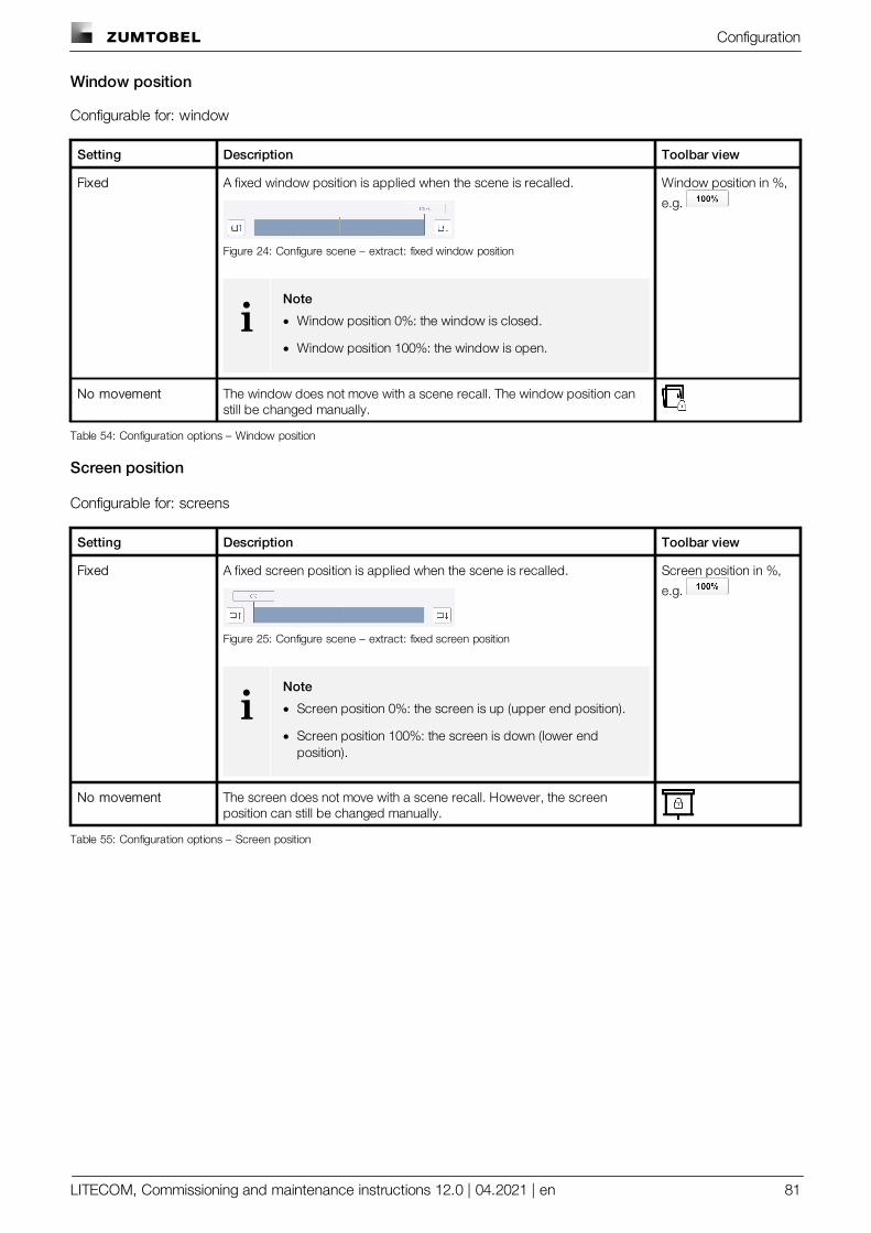
Configuration
LITECOM, Commissioning and maintenance instructions 12.0 | 04.2021 | en 81
Window position
Configurable for: window
Setting Description Toolbar view
Fixed A fixed window position is applied when the scene is recalled.
Figure 24: Configure scene – extract: fixed window position
iNote
· Window position 0%: the window is closed.
· Window position 100%: the window is open.
Window position in %,
e.g.
No movement The window does not move with a scene recall. The window position canstill be changed manually.
Table 54: Configuration options – Window position
Screen position
Configurable for: screens
Setting Description Toolbar view
Fixed A fixed screen position is applied when the scene is recalled.
Figure 25: Configure scene – extract: fixed screen position
iNote
· Screen position 0%: the screen is up (upper end position).
· Screen position 100%: the screen is down (lower endposition).
Screen position in %,
e.g.
No movement The screen does not move with a scene recall. However, the screenposition can still be changed manually.
Table 55: Configuration options – Screen position
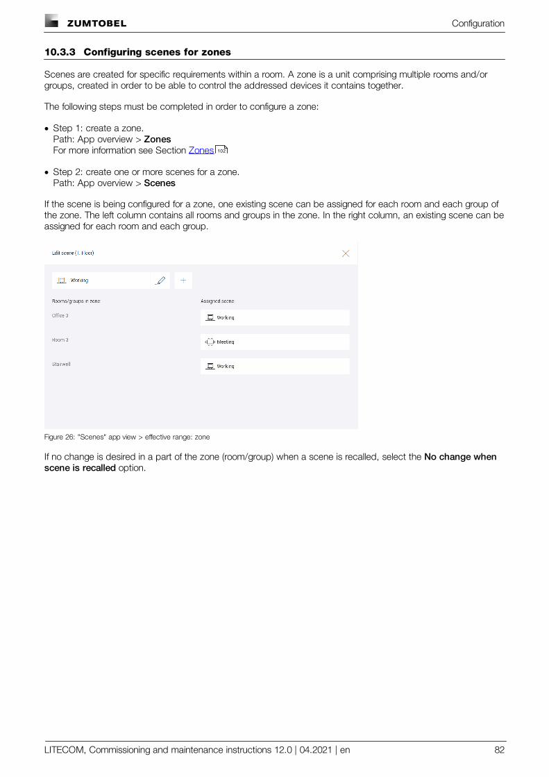
Configuration
LITECOM, Commissioning and maintenance instructions 12.0 | 04.2021 | en 82
10.3.3 Configuring scenes for zones
Scenes are created for specific requirements within a room. A zone is a unit comprising multiple rooms and/orgroups, created in order to be able to control the addressed devices it contains together.
The following steps must be completed in order to configure a zone:
· Step 1: create a zone.Path: App overview > ZonesFor more information see Section Zones
· Step 2: create one or more scenes for a zone.Path: App overview > Scenes
If the scene is being configured for a zone, one existing scene can be assigned for each room and each group ofthe zone. The left column contains all rooms and groups in the zone. In the right column, an existing scene can beassigned for each room and each group.
Figure 26: "Scenes" app view > effective range: zone
If no change is desired in a part of the zone (room/group) when a scene is recalled, select the No change whenscene is recalled option.
102
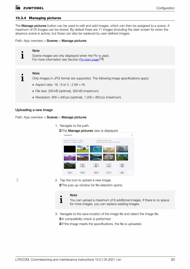
Configuration
LITECOM, Commissioning and maintenance instructions 12.0 | 04.2021 | en 83
10.3.4 Managing pictures
The Manage pictures button can be used to edit and add images, which can then be assigned to a scene. Amaximum of 20 images can be stored. By default there are 11 images (including the dark screen for when theabsence scene is active), but these can also be replaced by user-defined images.
Path: App overview > Scenes > Manage pictures
iNote
Scene images are only displayed when the Pix is used.For more information see Section Pix start page
iNote
Only images in JPG format are supported. The following image specifications apply:
· Aspect ratio: 16 : 9 or 3 : 2 (W × H)
· File size: 200 kB (optimal), 300 kB (maximum)
· Resolution: 800 × 600 px (optimal), 1,200 × 800 px (maximum)
Uploading a new image
Path: App overview > Scenes > Manage pictures
1. Navigate to the path.
ÜThe Manage pictures view is displayed.
2. Tap the icon to upload a new image.
ÜThe pop-up window for file selection opens.
iNote
You can upload a maximum of 9 additional images. If there is no spacefor more images, you can replace existing images.
3. Navigate to the save location of the image file and select the image file.
ÜA compatibility check is performed.
ÜIf the image meets the specifications, the file is uploaded.
19
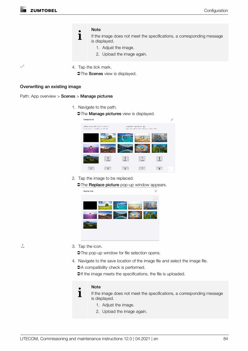
Configuration
LITECOM, Commissioning and maintenance instructions 12.0 | 04.2021 | en 84
iNote
If the image does not meet the specifications, a corresponding messageis displayed.
1. Adjust the image.
2. Upload the image again.
4. Tap the tick mark.
ÜThe Scenes view is displayed.
Overwriting an existing image
Path: App overview > Scenes > Manage pictures
1. Navigate to the path.
ÜThe Manage pictures view is displayed.
2. Tap the image to be replaced.
ÜThe Replace picture pop-up window appears.
3. Tap the icon.
ÜThe pop-up window for file selection opens.
4. Navigate to the save location of the image file and select the image file.
ÜA compatibility check is performed.
ÜIf the image meets the specifications, the file is uploaded.
iNote
If the image does not meet the specifications, a corresponding messageis displayed.
1. Adjust the image.
2. Upload the image again.
Configuration
LITECOM, Commissioning and maintenance instructions 12.0 | 04.2021 | en 85
5. Tap the icon.
ÜThe Manage pictures view is displayed.
iNote
In terms of data backups, the imported images are only included in a complete data backup.For more information see Section Data backup
10.4 Calendar
The Calendar app is used to manage all dates you wish to add as exceptions for other functions (such asconditional scene recall, presence linking).
Path: App overview > Calendar
Multiple date groups can be created. Each date group can contain any number of dates. There are two types ofdate group:
· Date group with annually recurring entries: this date group contains dates that recur annually (such as NewYear’s Day).
· Date group with one-off entries: this date group contains dates that only occur once or entries that occur ondates that differ from year to year.
iNote
We recommend creating a separate date group for the following dates:
Dates Type of date group
Fixed bank holidays Date group with annually recurring entries
Moveable bank holidays Date group with one-off entries
Company holidays Date group with one-off entries
Table 56: Recommendation for date groups
129
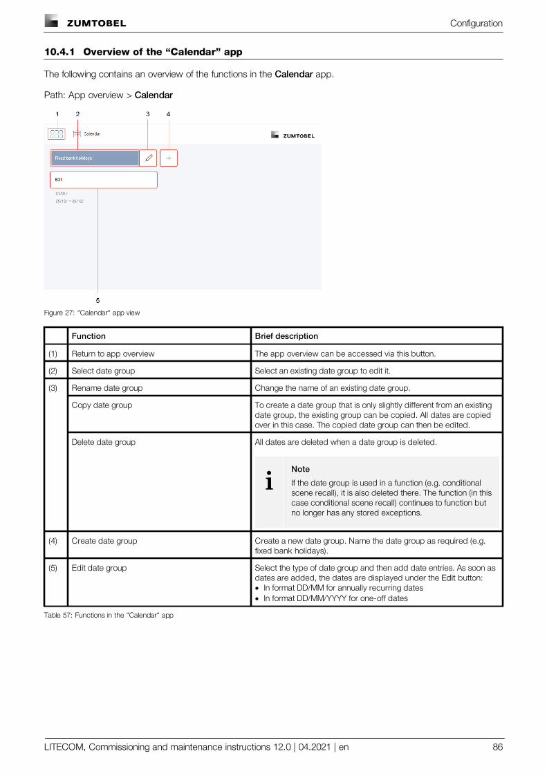
Configuration
LITECOM, Commissioning and maintenance instructions 12.0 | 04.2021 | en 86
10.4.1 Overview of the “Calendar” app
The following contains an overview of the functions in the Calendar app.
Path: App overview > Calendar
Figure 27: "Calendar" app view
Function Brief description
(1) Return to app overview The app overview can be accessed via this button.
(2) Select date group Select an existing date group to edit it.
(3) Rename date group Change the name of an existing date group.
Copy date group To create a date group that is only slightly different from an existingdate group, the existing group can be copied. All dates are copiedover in this case. The copied date group can then be edited.
Delete date group All dates are deleted when a date group is deleted.
iNote
If the date group is used in a function (e.g. conditionalscene recall), it is also deleted there. The function (in thiscase conditional scene recall) continues to function butno longer has any stored exceptions.
(4) Create date group Create a new date group. Name the date group as required (e.g.fixed bank holidays).
(5) Edit date group Select the type of date group and then add date entries. As soon asdates are added, the dates are displayed under the Edit button:· In format DD/MM for annually recurring dates· In format DD/MM/YYYY for one-off dates
Table 57: Functions in the "Calendar" app
Configuration
LITECOM, Commissioning and maintenance instructions 12.0 | 04.2021 | en 87
10.5 Conditional scene recall
A conditional scene recall is a way of controlling luminaires, blinds, windows and screens, in which certainconditions must be met in order for a scene to be recalled.
Path: App overview > Conditional scene recall
There are different types of conditional scene recall.
Type Description
Condition: time A scene is recalled in an effective range at a specific time. The scene can be recalled onan individual weekday or all weekdays. Date groups can also be added as exceptions.The scene recall can also be made to depend on the scene in a specific room or zone ifdesired.
iNoteFor more information and an application example see Section Condition:time
Condition: scene A certain scene is recalled in an effective range, but only if a specific scene is active in aspecific room or zone. The scene can be recalled on an individual weekday or allweekdays. Date groups can also be added as exceptions. You can also set a specificaction timeframe in which the scene recall takes place.
iNoteFor more information and an application example see Section Condition:scene
Condition: twilight A certain scene is recalled in an effective range but only if the illuminance measured bya specific light sensor exceeds or falls below a defined threshold for a certain amount oftime. The scene can be recalled on an individual weekday or all weekdays. Date groupscan also be added as exceptions. You can also set a specific action timeframe in whichthe scene recall takes place.
iNoteFor more information and an application example see Section Condition:twilight
Function: all off The absence scene is recalled in all rooms at a specific time. The scene can be recalledon an individual weekday or all weekdays. Date groups can also be added asexceptions.
iNoteFor more information and an application example see Section Function: alloff
90
92
93
94
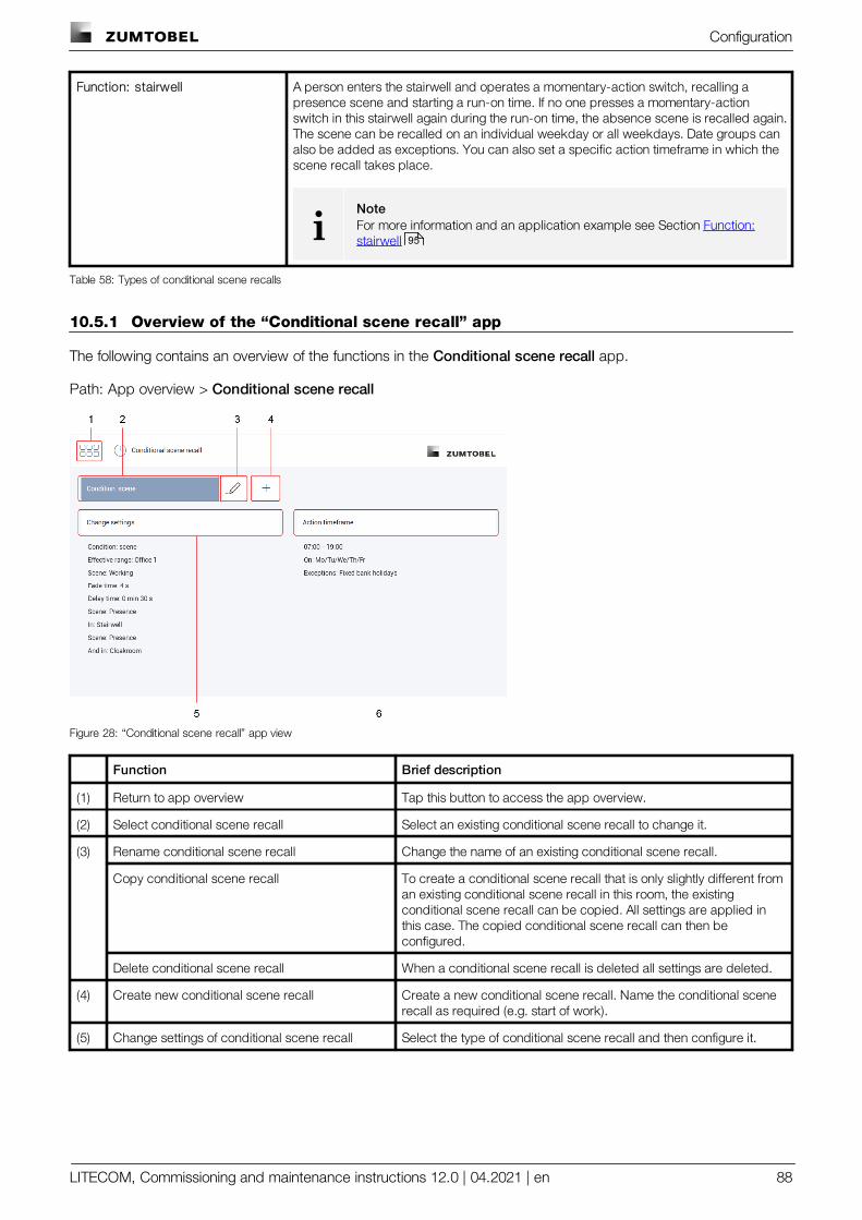
Configuration
LITECOM, Commissioning and maintenance instructions 12.0 | 04.2021 | en 88
Function: stairwell A person enters the stairwell and operates a momentary-action switch, recalling apresence scene and starting a run-on time. If no one presses a momentary-actionswitch in this stairwell again during the run-on time, the absence scene is recalled again.The scene can be recalled on an individual weekday or all weekdays. Date groups canalso be added as exceptions. You can also set a specific action timeframe in which thescene recall takes place.
iNoteFor more information and an application example see Section Function:stairwell
Table 58: Types of conditional scene recalls
10.5.1 Overview of the “Conditional scene recall” app
The following contains an overview of the functions in the Conditional scene recall app.
Path: App overview > Conditional scene recall
Figure 28: “Conditional scene recall” app view
Function Brief description
(1) Return to app overview Tap this button to access the app overview.
(2) Select conditional scene recall Select an existing conditional scene recall to change it.
(3) Rename conditional scene recall Change the name of an existing conditional scene recall.
Copy conditional scene recall To create a conditional scene recall that is only slightly different froman existing conditional scene recall in this room, the existingconditional scene recall can be copied. All settings are applied inthis case. The copied conditional scene recall can then beconfigured.
Delete conditional scene recall When a conditional scene recall is deleted all settings are deleted.
(4) Create new conditional scene recall Create a new conditional scene recall. Name the conditional scenerecall as required (e.g. start of work).
(5) Change settings of conditional scene recall Select the type of conditional scene recall and then configure it.
95
Configuration
LITECOM, Commissioning and maintenance instructions 12.0 | 04.2021 | en 89
Function Brief description
(6) Define action timeframe The action timeframe is a time in which the function is enabled. · Timeframe 1–3: define the action timeframe of the conditional
scene recall using a maximum of three timeframes. A timeframe of00:00–24:00 is stored as a default (conditional scene recall alwaysenabled). This function is only available for the following types ofconditional scene recall:o Condition: sceneo Condition: twilighto Function: stairwell
· On: Weekday on which the conditional scene recall occurs. Morethan one weekday can be selected.
· Exceptions: Date group with entries on which the conditionalscene recall does not occur. More than one date group can beselected.
iNote
Date groups must be defined in advance in the Calendar app. More information: Chapter Calendar .
Table 59: Functions of the “Conditional scene recall” app
85
Configuration
LITECOM, Commissioning and maintenance instructions 12.0 | 04.2021 | en 90
10.5.2 Configuration options
The following sections provide a description of the individual configuration options and additional examples.
· Condition: time
· Condition: scene
· Condition: twilight
· Function: all off
· Function: stairwell
Condition: time
The following table provides a description of the individual configuration options:
Parameter Description
Effective range Effective range (group, room or zone) in which the conditional scene recalloccurs.
Scene Scene recalled by the conditional scene recall.
Fade time The time it takes to change from the last value to the defined scene.
Time Time at which the scene is recalled.
Only if in Additional condition that can be added if desired by enabling the tick mark.Group, room or zone where a specific scene must be enabled in order forthe conditional scene recall to occur.
Scene(Only for condition Only if in)
Scene that must be enabled in this group/room/zone.
And when in Another additional condition that can be added if Only if in has beenspecified. Tap the tick mark to enable the condition.Group, room or zone where a specific scene must be enabled in order forthe conditional scene recall to occur.
Scene(Only for condition And when in)
Scene that must be enabled in this group/room/zone.
Table 60: Configuration options – conditional scene recall with condition “time”
Example
In room Office 1 on Monday to Friday, except on fixed bank holidays, the Working scene should be recalled at7:30 without a fade time. This scene recall should not depend on the scene in another room.
iNote
Over the action timeframe, select the weekdays on which the conditional scene recall is to takeplace, and the exceptions when it should not take place.Path: App overview > Conditional scene recall > Action timeframe
90
92
93
94
95

Configuration
LITECOM, Commissioning and maintenance instructions 12.0 | 04.2021 | en 91
Figure 29: Configuring the conditional scene recall with condition“time”
Figure 30: Summary of configuration for conditional scenerecall with condition “time”
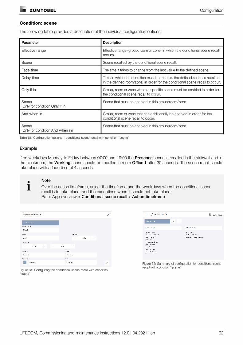
Configuration
LITECOM, Commissioning and maintenance instructions 12.0 | 04.2021 | en 92
Condition: scene
The following table provides a description of the individual configuration options:
Parameter Description
Effective range Effective range (group, room or zone) in which the conditional scene recalloccurs.
Scene Scene recalled by the conditional scene recall.
Fade time The time it takes to change from the last value to the defined scene.
Delay time Time in which the condition must be met (i.e. the defined scene is recalledin the defined room/zone) in order for the conditional scene recall to occur.
Only if in Group, room or zone where a specific scene must be enabled in order forthe conditional scene recall to occur.
Scene(Only for condition Only if in)
Scene that must be enabled in this group/room/zone.
And when in Group, room or zone that can additionally be enabled in order for theconditional scene recall to occur.
Scene(Only for condition And when in)
Scene that must be enabled in this group/room/zone.
Table 61: Configuration options – conditional scene recall with condition “scene”
Example
If on weekdays Monday to Friday between 07:00 and 19:00 the Presence scene is recalled in the stairwell and inthe cloakroom, the Working scene should be recalled in room Office 1 after 30 seconds. The scene recall shouldtake place with a fade time of 4 seconds.
iNote
Over the action timeframe, select the timeframe and the weekdays when the conditional scenerecall is to take place, and the exceptions when it should not take place.Path: App overview > Conditional scene recall > Action timeframe
Figure 31: Configuring the conditional scene recall with condition“scene”
Figure 32: Summary of configuration for conditional scenerecall with condition “scene”
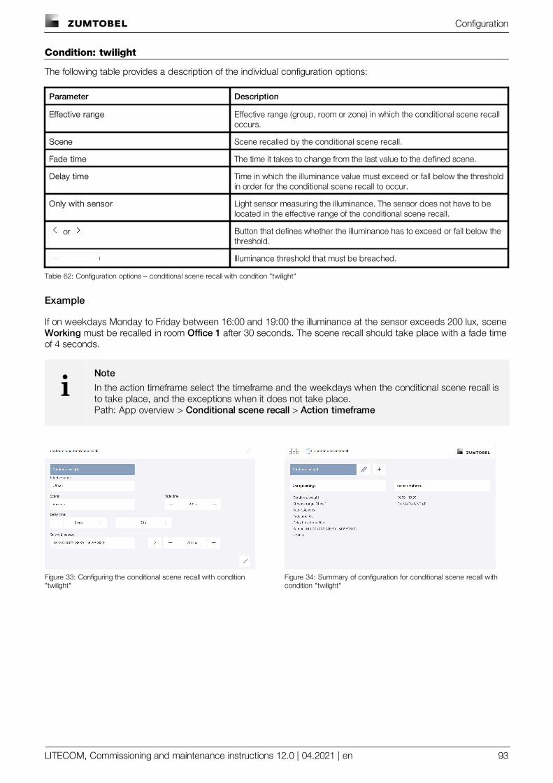
Configuration
LITECOM, Commissioning and maintenance instructions 12.0 | 04.2021 | en 93
Condition: twilight
The following table provides a description of the individual configuration options:
Parameter Description
Effective range Effective range (group, room or zone) in which the conditional scene recalloccurs.
Scene Scene recalled by the conditional scene recall.
Fade time The time it takes to change from the last value to the defined scene.
Delay time Time in which the illuminance value must exceed or fall below the thresholdin order for the conditional scene recall to occur.
Only with sensor Light sensor measuring the illuminance. The sensor does not have to belocated in the effective range of the conditional scene recall.
or Button that defines whether the illuminance has to exceed or fall below thethreshold.
Illuminance threshold that must be breached.
Table 62: Configuration options – conditional scene recall with condition "twilight"
Example
If on weekdays Monday to Friday between 16:00 and 19:00 the illuminance at the sensor exceeds 200 lux, scene Working must be recalled in room Office 1 after 30 seconds. The scene recall should take place with a fade timeof 4 seconds.
iNote
In the action timeframe select the timeframe and the weekdays when the conditional scene recall isto take place, and the exceptions when it does not take place.Path: App overview > Conditional scene recall > Action timeframe
Figure 33: Configuring the conditional scene recall with condition"twilight"
Figure 34: Summary of configuration for conditional scene recall withcondition "twilight"
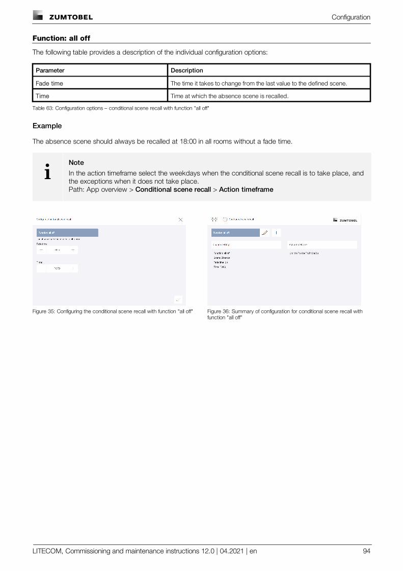
Configuration
LITECOM, Commissioning and maintenance instructions 12.0 | 04.2021 | en 94
Function: all off
The following table provides a description of the individual configuration options:
Parameter Description
Fade time The time it takes to change from the last value to the defined scene.
Time Time at which the absence scene is recalled.
Table 63: Configuration options – conditional scene recall with function "all off"
Example
The absence scene should always be recalled at 18:00 in all rooms without a fade time.
iNote
In the action timeframe select the weekdays when the conditional scene recall is to take place, andthe exceptions when it does not take place.Path: App overview > Conditional scene recall > Action timeframe
Figure 35: Configuring the conditional scene recall with function "all off" Figure 36: Summary of configuration for conditional scene recall withfunction "all off"
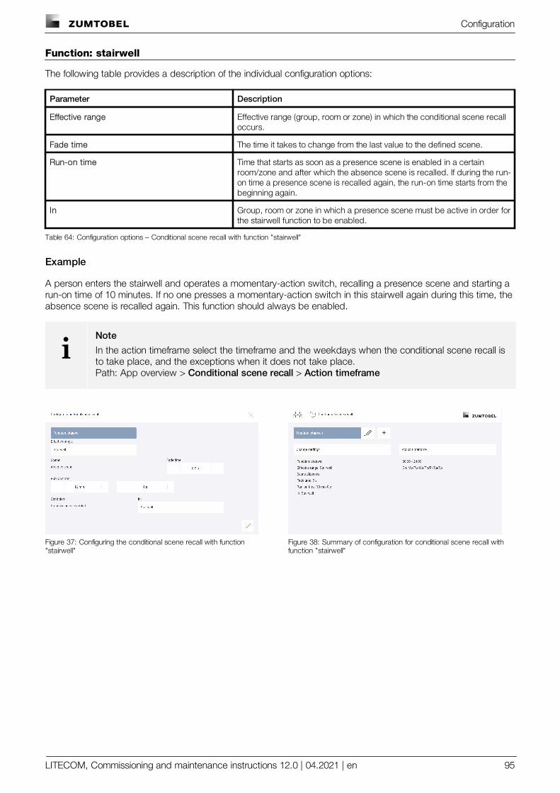
Configuration
LITECOM, Commissioning and maintenance instructions 12.0 | 04.2021 | en 95
Function: stairwell
The following table provides a description of the individual configuration options:
Parameter Description
Effective range Effective range (group, room or zone) in which the conditional scene recalloccurs.
Fade time The time it takes to change from the last value to the defined scene.
Run-on time Time that starts as soon as a presence scene is enabled in a certainroom/zone and after which the absence scene is recalled. If during the run-on time a presence scene is recalled again, the run-on time starts from thebeginning again.
In Group, room or zone in which a presence scene must be active in order forthe stairwell function to be enabled.
Table 64: Configuration options – Conditional scene recall with function "stairwell"
Example
A person enters the stairwell and operates a momentary-action switch, recalling a presence scene and starting arun-on time of 10 minutes. If no one presses a momentary-action switch in this stairwell again during this time, theabsence scene is recalled again. This function should always be enabled.
iNote
In the action timeframe select the timeframe and the weekdays when the conditional scene recall isto take place, and the exceptions when it does not take place.Path: App overview > Conditional scene recall > Action timeframe
Figure 37: Configuring the conditional scene recall with function"stairwell"
Figure 38: Summary of configuration for conditional scene recall withfunction "stairwell"
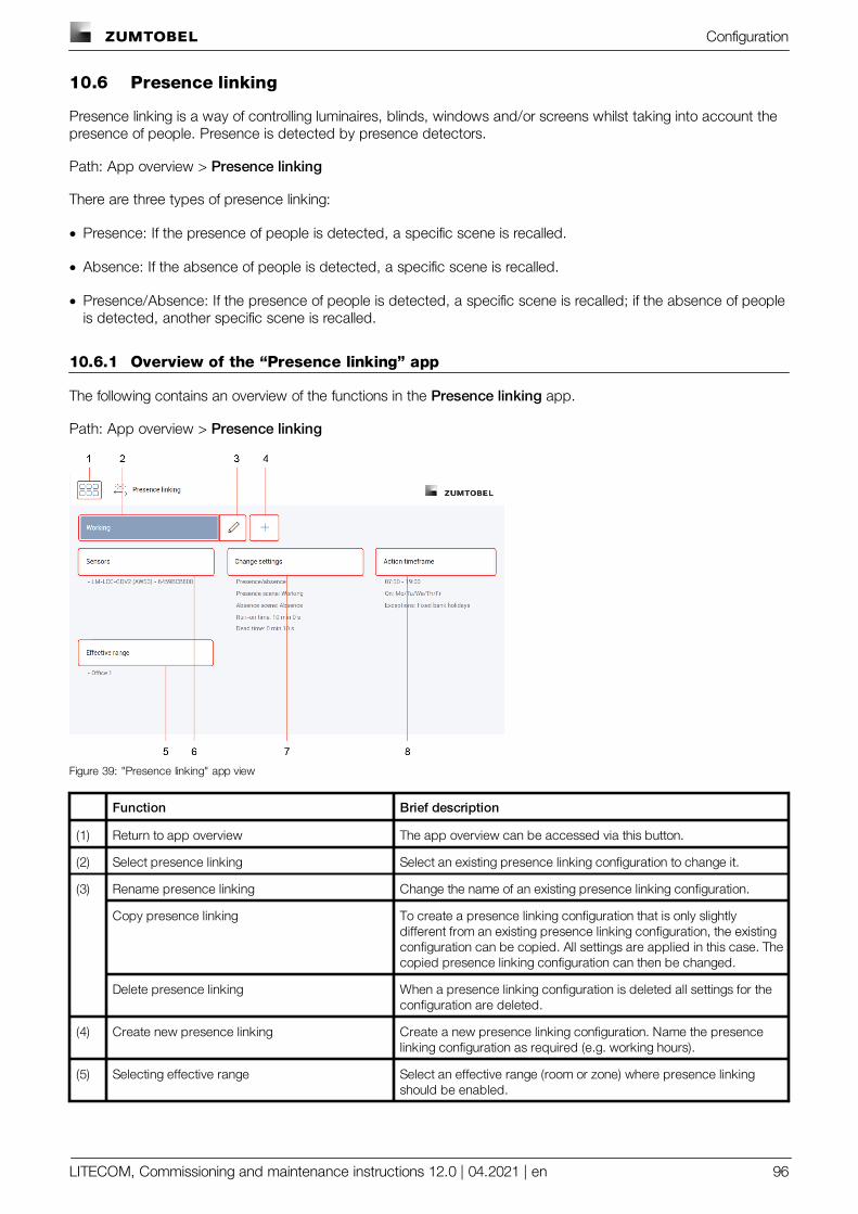
Configuration
LITECOM, Commissioning and maintenance instructions 12.0 | 04.2021 | en 96
10.6 Presence linking
Presence linking is a way of controlling luminaires, blinds, windows and/or screens whilst taking into account thepresence of people. Presence is detected by presence detectors.
Path: App overview > Presence linking
There are three types of presence linking:
· Presence: If the presence of people is detected, a specific scene is recalled.
· Absence: If the absence of people is detected, a specific scene is recalled.
· Presence/Absence: If the presence of people is detected, a specific scene is recalled; if the absence of peopleis detected, another specific scene is recalled.
10.6.1 Overview of the “Presence linking” app
The following contains an overview of the functions in the Presence linking app.
Path: App overview > Presence linking
Figure 39: "Presence linking" app view
Function Brief description
(1) Return to app overview The app overview can be accessed via this button.
(2) Select presence linking Select an existing presence linking configuration to change it.
(3) Rename presence linking Change the name of an existing presence linking configuration.
Copy presence linking To create a presence linking configuration that is only slightlydifferent from an existing presence linking configuration, the existingconfiguration can be copied. All settings are applied in this case. Thecopied presence linking configuration can then be changed.
Delete presence linking When a presence linking configuration is deleted all settings for theconfiguration are deleted.
(4) Create new presence linking Create a new presence linking configuration. Name the presencelinking configuration as required (e.g. working hours).
(5) Selecting effective range Select an effective range (room or zone) where presence linkingshould be enabled.
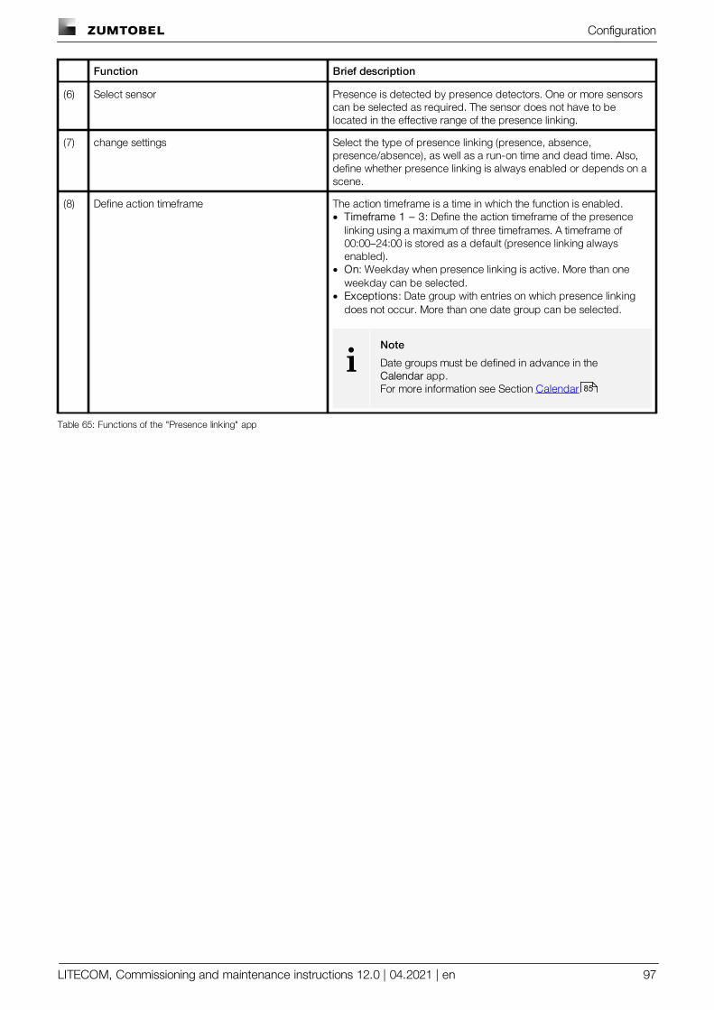
Configuration
LITECOM, Commissioning and maintenance instructions 12.0 | 04.2021 | en 97
Function Brief description
(6) Select sensor Presence is detected by presence detectors. One or more sensorscan be selected as required. The sensor does not have to belocated in the effective range of the presence linking.
(7) change settings Select the type of presence linking (presence, absence,presence/absence), as well as a run-on time and dead time. Also,define whether presence linking is always enabled or depends on ascene.
(8) Define action timeframe The action timeframe is a time in which the function is enabled. · Timeframe 1 – 3: Define the action timeframe of the presence
linking using a maximum of three timeframes. A timeframe of00:00–24:00 is stored as a default (presence linking alwaysenabled).
· On: Weekday when presence linking is active. More than oneweekday can be selected.
· Exceptions: Date group with entries on which presence linkingdoes not occur. More than one date group can be selected.
iNote
Date groups must be defined in advance in the Calendar app.For more information see Section Calendar
Table 65: Functions of the "Presence linking" app
85
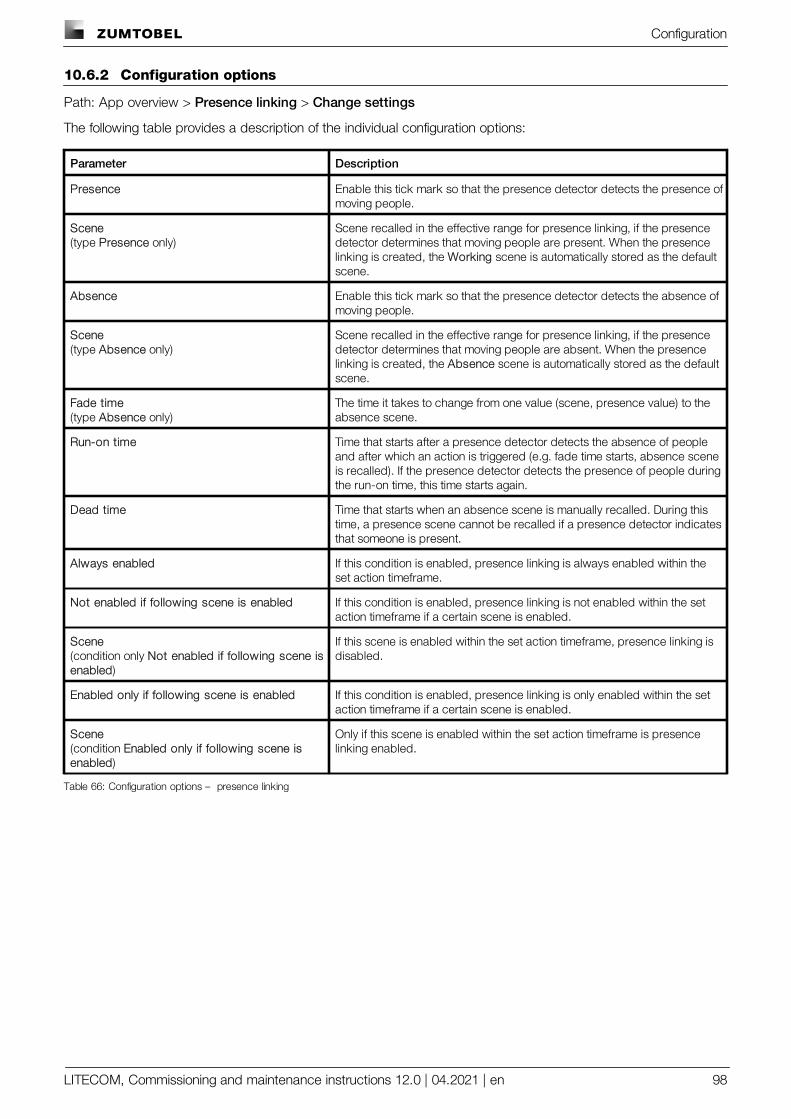
Configuration
LITECOM, Commissioning and maintenance instructions 12.0 | 04.2021 | en 98
10.6.2 Configuration options
Path: App overview > Presence linking > Change settings
The following table provides a description of the individual configuration options:
Parameter Description
Presence Enable this tick mark so that the presence detector detects the presence ofmoving people.
Scene(type Presence only)
Scene recalled in the effective range for presence linking, if the presencedetector determines that moving people are present. When the presencelinking is created, the Working scene is automatically stored as the defaultscene.
Absence Enable this tick mark so that the presence detector detects the absence ofmoving people.
Scene(type Absence only)
Scene recalled in the effective range for presence linking, if the presencedetector determines that moving people are absent. When the presencelinking is created, the Absence scene is automatically stored as the defaultscene.
Fade time(type Absence only)
The time it takes to change from one value (scene, presence value) to theabsence scene.
Run-on time Time that starts after a presence detector detects the absence of peopleand after which an action is triggered (e.g. fade time starts, absence sceneis recalled). If the presence detector detects the presence of people duringthe run-on time, this time starts again.
Dead time Time that starts when an absence scene is manually recalled. During thistime, a presence scene cannot be recalled if a presence detector indicatesthat someone is present.
Always enabled If this condition is enabled, presence linking is always enabled within theset action timeframe.
Not enabled if following scene is enabled If this condition is enabled, presence linking is not enabled within the setaction timeframe if a certain scene is enabled.
Scene(condition only Not enabled if following scene isenabled)
If this scene is enabled within the set action timeframe, presence linking isdisabled.
Enabled only if following scene is enabled If this condition is enabled, presence linking is only enabled within the setaction timeframe if a certain scene is enabled.
Scene(condition Enabled only if following scene isenabled)
Only if this scene is enabled within the set action timeframe is presencelinking enabled.
Table 66: Configuration options – presence linking
Configuration
LITECOM, Commissioning and maintenance instructions 12.0 | 04.2021 | en 99
10.7 Protective functions
Protective functions can be used to protect the building services installed in your LITECOM system fromenvironmental damage (such as from storms, rain or ice).
A protective function is triggered by a sensor of the weather station or by an input contact. You can definewhether the protective function is enabled, e.g. from a specific wind speed or when the input contact is open orclosed. As soon as the protective function is enabled, the building services are locked and depending on theconfiguration, can either no longer be operated or have limited operation.
Path: App overview > Protective functions
Integrating protective function
The following steps are required:
· Step 1: create new protective function.Path: App overview > Protective functions >
· Step 2: use protective function.Path: App overview > Protective functions > Configure > tick mark is enabled as default
iNote
· If the tick mark is disabled, the protective function is also not enabled if the input contact triggers.
· Once the tick mark has been removed, all blinds and/or windows are unlocked in the effectiverange.
· Step 3: select and configure the trigger.Path: App overview > Protective functions > Configure > Trigger
iNote
· You can select the following triggers:
o Wind speed sensor (Wind) of weather station
o Rain sensor (Rain) of weather station
o Input contact which has been configured for wind or rain (Input contact).
· In the case of a wind speed sensor of the weather station, configure the wind speed starting fromwhich the protective function is active.
· In the case of an input contact, select whether the protective function should be triggered foropen or closed contact.
· Step 4: select effective range (individual or multiple rooms and groups).Path: App overview > Protective functions > Configure > Effective range
· Step 5: configure protective function.Path: App overview > Protective functions > ConfigureFor more information see Section Configuration options 101
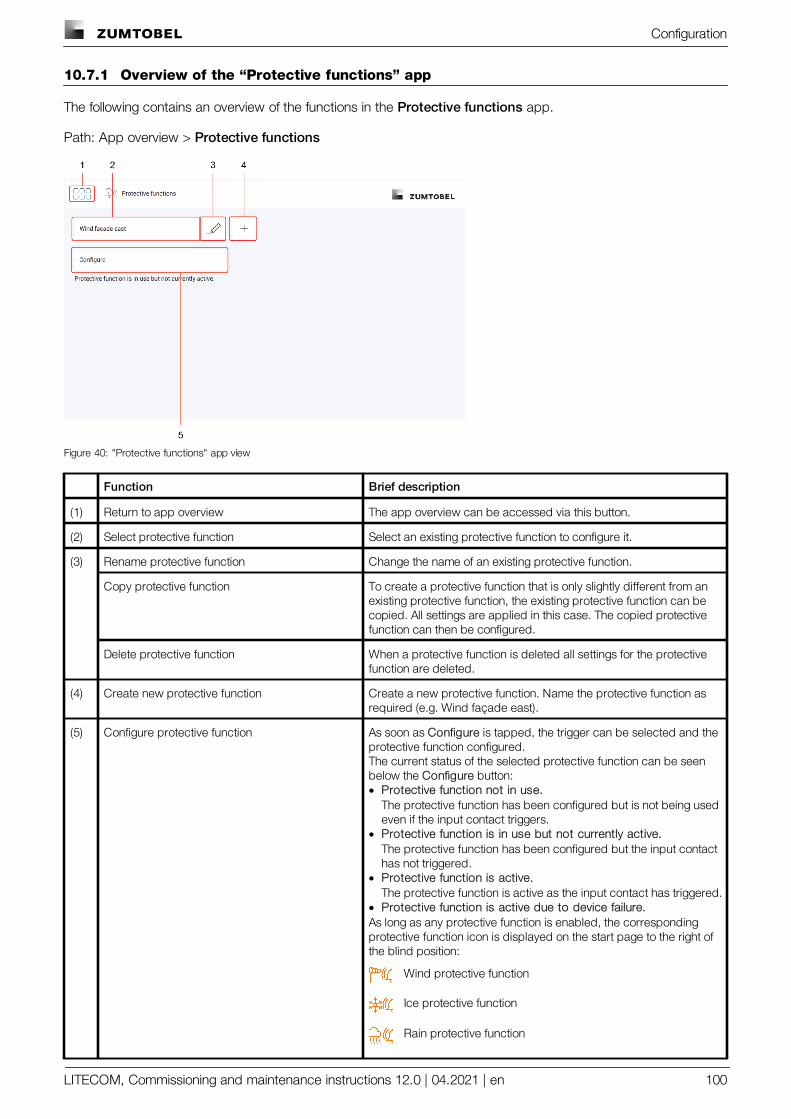
Configuration
LITECOM, Commissioning and maintenance instructions 12.0 | 04.2021 | en 100
10.7.1 Overview of the “Protective functions” app
The following contains an overview of the functions in the Protective functions app.
Path: App overview > Protective functions
Figure 40: "Protective functions" app view
Function Brief description
(1) Return to app overview The app overview can be accessed via this button.
(2) Select protective function Select an existing protective function to configure it.
(3) Rename protective function Change the name of an existing protective function.
Copy protective function To create a protective function that is only slightly different from anexisting protective function, the existing protective function can becopied. All settings are applied in this case. The copied protectivefunction can then be configured.
Delete protective function When a protective function is deleted all settings for the protectivefunction are deleted.
(4) Create new protective function Create a new protective function. Name the protective function asrequired (e.g. Wind façade east).
(5) Configure protective function As soon as Configure is tapped, the trigger can be selected and theprotective function configured.The current status of the selected protective function can be seenbelow the Configure button:· Protective function not in use.
The protective function has been configured but is not being usedeven if the input contact triggers.
· Protective function is in use but not currently active.The protective function has been configured but the input contacthas not triggered.
· Protective function is active.The protective function is active as the input contact has triggered.
· Protective function is active due to device failure.As long as any protective function is enabled, the correspondingprotective function icon is displayed on the start page to the right ofthe blind position:
Wind protective function
Ice protective function
Rain protective function
Configuration
LITECOM, Commissioning and maintenance instructions 12.0 | 04.2021 | en 101
Function Brief description
Protective functions with different triggers; e.g. rain alarm ingroup 1 and wind alarm in group 2
Table 67: Functions in the "Protective functions" app
10.7.2 Configuration options
Path: App overview > Protective functions > Configure
The following table provides a description of the individual configuration options:
Parameter Description
Mode of operation Mode of operation locked by the protective function.
Lower limit of the movement range The movement range defines the capabilities of blinds or a window to movebetween the end positions if the blinds/window has an actuator which isable to measure the distance covered and send feedback about thecurrent position of the blinds/window. Setting a lower and upper limit of themovement range can limit the range further.
iNote
If the same values are selected for both the lower and theupper limit of the movement range, the blinds or the windoware locked at this value and can no longer be moved.
Upper limit of the movement range
Priority (15 = highest priority) If multiple protective functions are active at the same time, the prioritysetting can be used to define the order in which the protective functionstake precedence. A protective function with priority 15 is implementedbefore (i.e. takes precedence over) a protective function with priority 14.
Delay time Time in which the condition must be met in order for the protective functionto become enabled, e.g. the input contact must be closed or opendepending on the configuration; the wind speed sensor must measure acertain wind speed.
Run-on time Time that starts as soon as a weather station sensor is triggered or the inputcontact closes/opens again (depending on the configuration) and afterwhich the protective function is disabled. If during the run-on time aweather station sensor or the input contact is triggered again, the run-ontime starts from the beginning again.
Table 68: Configuration options – Protective functions
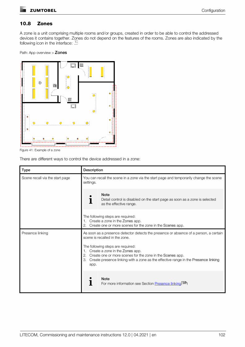
Configuration
LITECOM, Commissioning and maintenance instructions 12.0 | 04.2021 | en 102
10.8 Zones
A zone is a unit comprising multiple rooms and/or groups, created in order to be able to control the addresseddevices it contains together. Zones do not depend on the features of the rooms. Zones are also indicated by thefollowing icon in the interface:
Path: App overview > Zones
Figure 41: Example of a zone
There are different ways to control the device addressed in a zone:
Type Description
Scene recall via the start page You can recall the scene in a zone via the start page and temporarily change the scenesettings.
iNoteDetail control is disabled on the start page as soon as a zone is selectedas the effective range.
The following steps are required:1. Create a zone in the Zones app.2. Create one or more scenes for the zone in the Scenes app.
Presence linking As soon as a presence detector detects the presence or absence of a person, a certainscene is recalled in the zone.
The following steps are required:1. Create a zone in the Zones app.2. Create one or more scenes for the zone in the Scenes app.3. Create presence linking with a zone as the effective range in the Presence linking
app.
i NoteFor more information see Section Presence linking 96
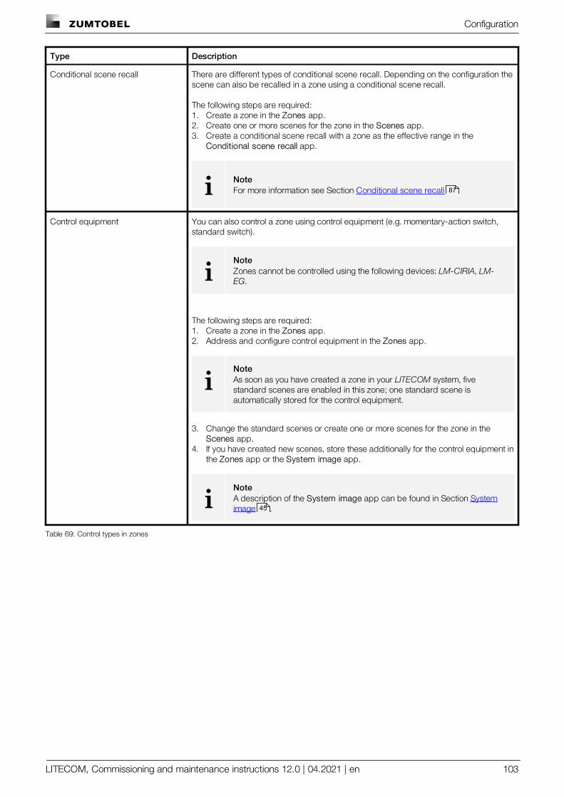
Configuration
LITECOM, Commissioning and maintenance instructions 12.0 | 04.2021 | en 103
Type Description
Conditional scene recall There are different types of conditional scene recall. Depending on the configuration thescene can also be recalled in a zone using a conditional scene recall.
The following steps are required:1. Create a zone in the Zones app.2. Create one or more scenes for the zone in the Scenes app.3. Create a conditional scene recall with a zone as the effective range in the
Conditional scene recall app.
i NoteFor more information see Section Conditional scene recall
Control equipment You can also control a zone using control equipment (e.g. momentary-action switch,standard switch).
iNoteZones cannot be controlled using the following devices: LM-CIRIA, LM-EG.
The following steps are required:1. Create a zone in the Zones app.2. Address and configure control equipment in the Zones app.
iNoteAs soon as you have created a zone in your LITECOM system, fivestandard scenes are enabled in this zone; one standard scene isautomatically stored for the control equipment.
3. Change the standard scenes or create one or more scenes for the zone in the Scenes app.
4. If you have created new scenes, store these additionally for the control equipment inthe Zones app or the System image app.
iNoteA description of the System image app can be found in Section Systemimage .
Table 69: Control types in zones
87
45
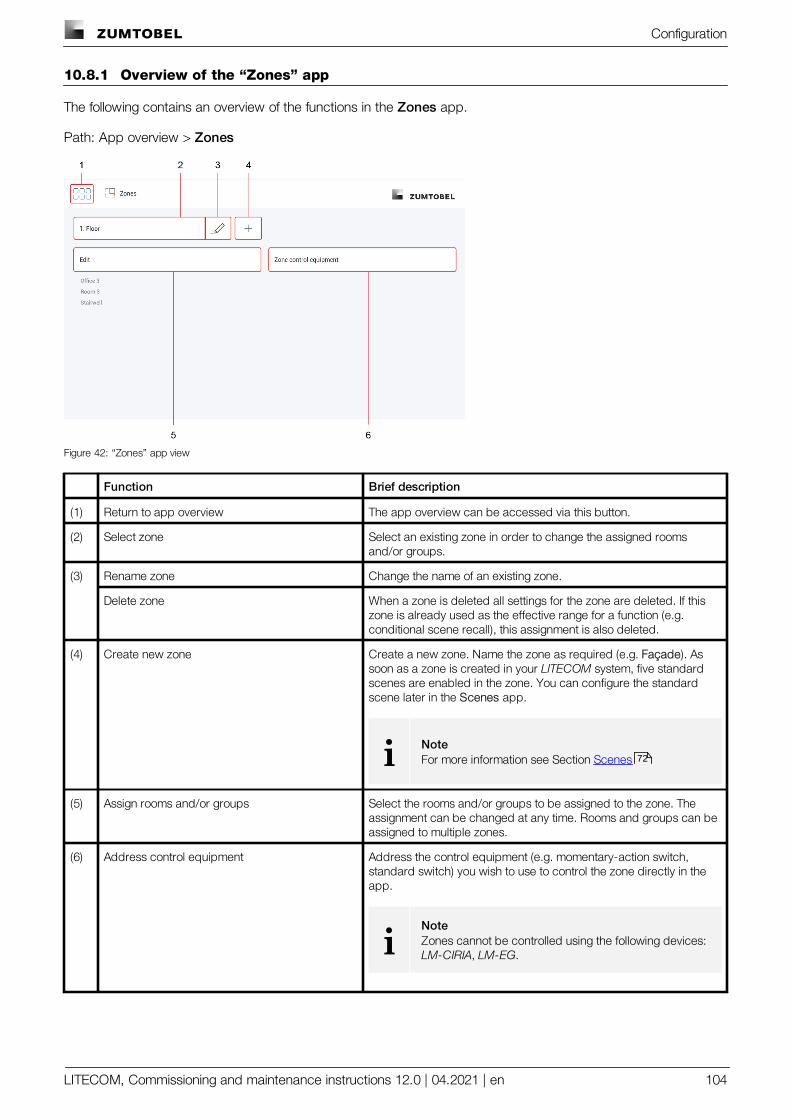
Configuration
LITECOM, Commissioning and maintenance instructions 12.0 | 04.2021 | en 104
10.8.1 Overview of the “Zones” app
The following contains an overview of the functions in the Zones app.
Path: App overview > Zones
Figure 42: “Zones” app view
Function Brief description
(1) Return to app overview The app overview can be accessed via this button.
(2) Select zone Select an existing zone in order to change the assigned roomsand/or groups.
(3) Rename zone Change the name of an existing zone.
Delete zone When a zone is deleted all settings for the zone are deleted. If thiszone is already used as the effective range for a function (e.g.conditional scene recall), this assignment is also deleted.
(4) Create new zone Create a new zone. Name the zone as required (e.g. Façade). Assoon as a zone is created in your LITECOM system, five standardscenes are enabled in the zone. You can configure the standardscene later in the Scenes app.
i NoteFor more information see Section Scenes
(5) Assign rooms and/or groups Select the rooms and/or groups to be assigned to the zone. Theassignment can be changed at any time. Rooms and groups can beassigned to multiple zones.
(6) Address control equipment Address the control equipment (e.g. momentary-action switch,standard switch) you wish to use to control the zone directly in theapp.
iNoteZones cannot be controlled using the following devices: LM-CIRIA, LM-EG.
72
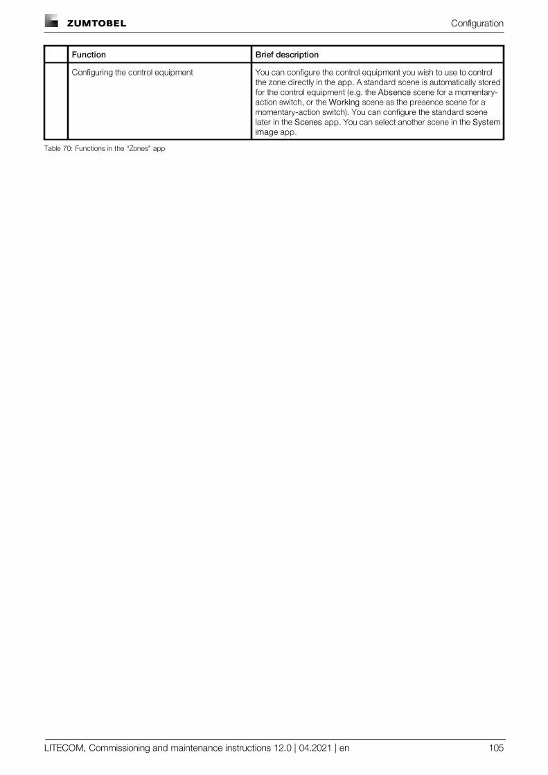
Configuration
LITECOM, Commissioning and maintenance instructions 12.0 | 04.2021 | en 105
Function Brief description
Configuring the control equipment You can configure the control equipment you wish to use to controlthe zone directly in the app. A standard scene is automatically storedfor the control equipment (e.g. the Absence scene for a momentary-action switch, or the Working scene as the presence scene for amomentary-action switch). You can configure the standard scenelater in the Scenes app. You can select another scene in the Systemimage app.
Table 70: Functions in the “Zones” app

Configuration
LITECOM, Commissioning and maintenance instructions 12.0 | 04.2021 | en 106
10.9 Selecting the start page
Three different start pages are available:
· Default start pageFor more information see Section Start page
· Pix start pageFor more information see Section Pix start page
· Emergency lightingFor more information see Self-contained emergency luminaires manual
Opening the start page
1. Open the app overview.
2. Select the Start page app.
ÜThe default start page opens.
Opening the Pix
1. Open the app overview.
2. Select the Pix app.
ÜThe Pix start page opens.
Setting the user-defined start page
In order for the desired start page to be displayed every time the LITECOM web application is opened, the startpage preference can be defined.
Path: App overview > Basic settings > Start page settings
1. Navigate to the path.
2. Tap the button with the currently defined start page. The default start page is defined as standard.
ÜThe Select user-defined start page view opens.
3. Select the start page to be displayed when the LITECOM web application is opened.
ÜThe Start page settings view is displayed.
ÜThe settings are saved.
ÜThe preferred start page is displayed the next time the web application is opened.
16
19

Configuration
LITECOM, Commissioning and maintenance instructions 12.0 | 04.2021 | en 107
10.10 User management
The User management app can be used to create users, who can control the individual rooms, groups andzones without having access to the rest of the functions of the LITECOM web application. There are three differenttypes of users available for active use of the User management app:
· Administrator: the administrator is not created and cannot be deleted. The administrator is able to create anddelete other users and managers and reset their passwords. They can create different profiles (comprisingrooms, groups and zones) and assign them to users and managers. They can also enable and disable the Usermanagement function. The administrator is the only one who can set the Emergency lighting start page as adefault and access the rest of the functions of the LITECOM web application, even if the User managementapp has been enabled.
· Manager: managers are user types that can create and delete other users and managers and reset theirpasswords. Managers can also create different profiles (comprising rooms, groups and zones) and assign themto users and other managers.
· User: users can only control areas (rooms, groups and/or zones) assigned to them.
Enabling User management
Path: App overview > User management
iNote
The administrator is the only one who can enable the User management app for the first time.
iNote
If you wish to use the User management app with LITECOM infinity, ensure that the cloud is set upfirst and only then is the app enabled.
1. Navigate to the path.
ÜThe User management view is displayed.
2. Tap the button.
ÜThe login screen for the administrator opens.
iNote
· The user name admin is preset as standard and cannot bechanged.
· The Old password: field can be left blank.
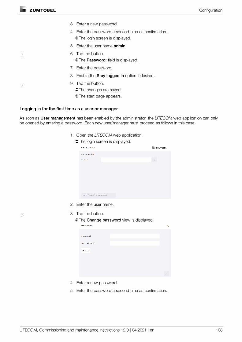
Configuration
LITECOM, Commissioning and maintenance instructions 12.0 | 04.2021 | en 108
adfs 3. Enter a new password.
4. Enter the password a second time as confirmation.
ÜThe login screen is displayed.
5. Enter the user name admin.
6. Tap the button.
ÜThe Password: field is displayed.
7. Enter the password.
8. Enable the Stay logged in option if desired.
9. Tap the button.
ÜThe changes are saved.
ÜThe start page appears.
Logging in for the first time as a user or manager
As soon as User management has been enabled by the administrator, the LITECOM web application can onlybe opened by entering a password. Each new user/manager must proceed as follows in this case:
1. Open the LITECOM web application.
ÜThe login screen is displayed.
2. Enter the user name.
3. Tap the button.
ÜThe Change password view is displayed.
4. Enter a new password.
5. Enter the password a second time as confirmation.
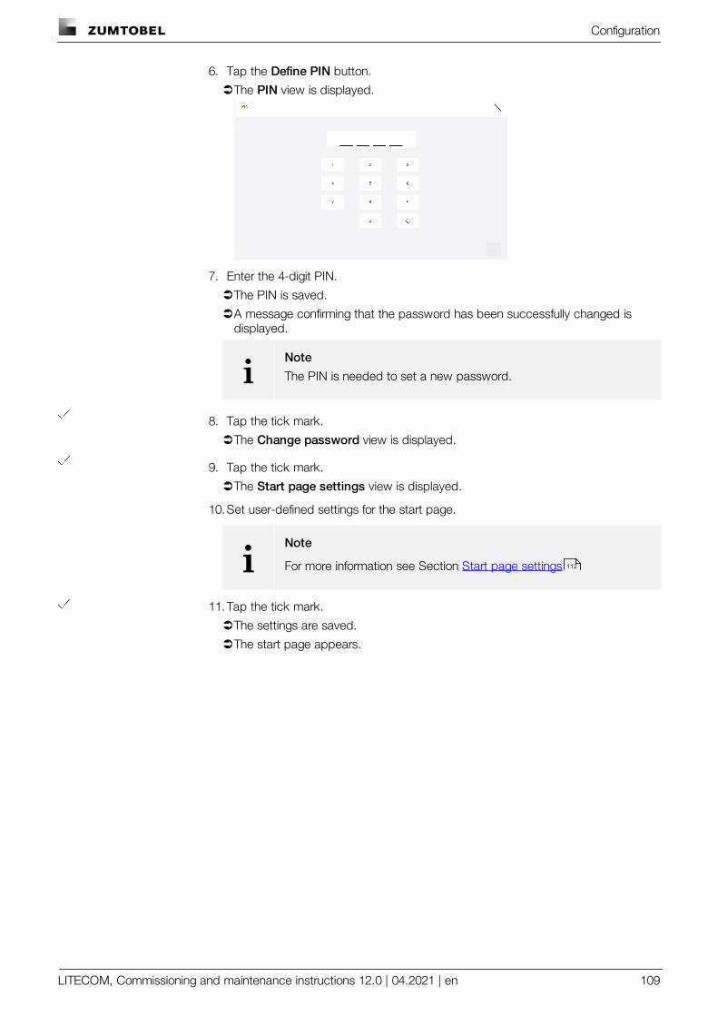
Configuration
LITECOM, Commissioning and maintenance instructions 12.0 | 04.2021 | en 109
6. Tap the Define PIN button.
ÜThe PIN view is displayed.
7. Enter the 4-digit PIN.
ÜThe PIN is saved.
ÜA message confirming that the password has been successfully changed isdisplayed.
iNote
The PIN is needed to set a new password.
8. Tap the tick mark.
ÜThe Change password view is displayed.
9. Tap the tick mark.
ÜThe Start page settings view is displayed.
10.Set user-defined settings for the start page.
iNote
For more information see Section Start page settings
11.Tap the tick mark.
ÜThe settings are saved.
ÜThe start page appears.
112
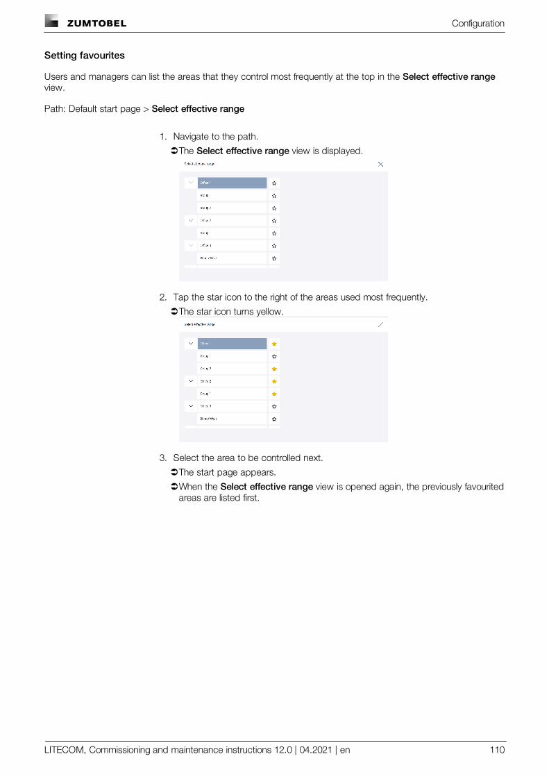
Configuration
LITECOM, Commissioning and maintenance instructions 12.0 | 04.2021 | en 110
Setting favourites
Users and managers can list the areas that they control most frequently at the top in the Select effective rangeview.
Path: Default start page > Select effective range
1. Navigate to the path.
ÜThe Select effective range view is displayed.
2. Tap the star icon to the right of the areas used most frequently.
ÜThe star icon turns yellow.
3. Select the area to be controlled next.
ÜThe start page appears.
ÜWhen the Select effective range view is opened again, the previously favouritedareas are listed first.
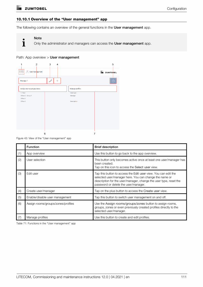
Configuration
LITECOM, Commissioning and maintenance instructions 12.0 | 04.2021 | en 111
10.10.1 Overview of the “User management” app
The following contains an overview of the general functions in the User management app.
iNote
Only the administrator and managers can access the User management app.
Path: App overview > User management
Figure 43: View of the “User management” app
Function Brief description
(1) App overview Use this button to go back to the app overview.
(2) User selection This button only becomes active once at least one user/manager hasbeen created.Tap on this icon to access the Select user view.
(3) Edit user Tap this button to access the Edit user view. You can edit theselected user/manager here. You can change the name ordescription for the user/manager, change the user type, reset thepassword or delete the user/manager.
(4) Create user/manager Tap on the plus button to access the Create user view.
(5) Enable/disable user management Tap this button to switch user management on and off.
(6) Assign rooms/groups/zones/profiles Use the Assign rooms/groups/zones button to assign rooms,groups, zones or even previously created profiles directly to theselected user/manager.
(7) Manage profiles Use this button to create and edit profiles.
Table 71: Functions in the “User management” app
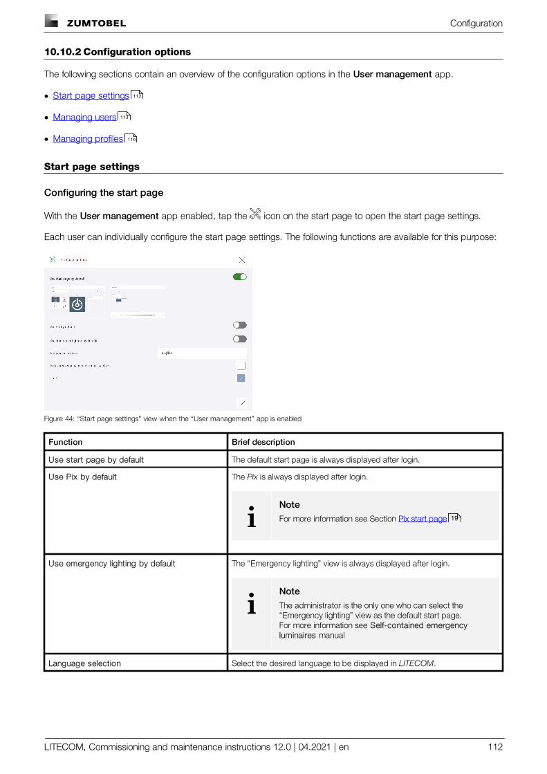
Configuration
LITECOM, Commissioning and maintenance instructions 12.0 | 04.2021 | en 112
10.10.2 Configuration options
The following sections contain an overview of the configuration options in the User management app.
· Start page settings
· Managing users
· Managing profiles
Start page settings
Configuring the start page
With the User management app enabled, tap the icon on the start page to open the start page settings.
Each user can individually configure the start page settings. The following functions are available for this purpose:
Figure 44: “Start page settings” view when the “User management” app is enabled
Function Brief description
Use start page by default The default start page is always displayed after login.
Use Pix by default The Pix is always displayed after login.
iNoteFor more information see Section Pix start page
Use emergency lighting by default The “Emergency lighting” view is always displayed after login.
iNoteThe administrator is the only one who can select the“Emergency lighting” view as the default start page.For more information see Self-contained emergencyluminaires manual
Language selection Select the desired language to be displayed in LITECOM.
112
113
116
19
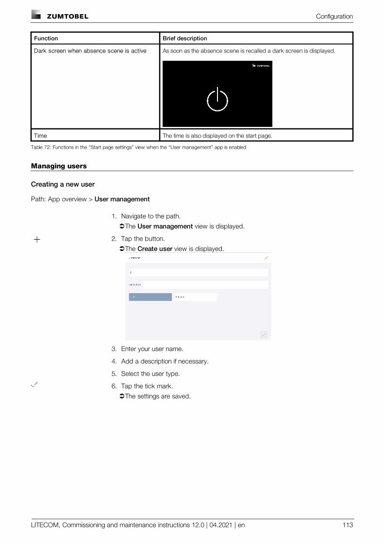
Configuration
LITECOM, Commissioning and maintenance instructions 12.0 | 04.2021 | en 113
Function Brief description
Dark screen when absence scene is active As soon as the absence scene is recalled a dark screen is displayed.
Time The time is also displayed on the start page.
Table 72: Functions in the “Start page settings” view when the “User management” app is enabled
Managing users
Creating a new user
Path: App overview > User management
1. Navigate to the path.
ÜThe User management view is displayed.
2. Tap the button.
ÜThe Create user view is displayed.
3. Enter your user name.
4. Add a description if necessary.
5. Select the user type.
6. Tap the tick mark.
ÜThe settings are saved.
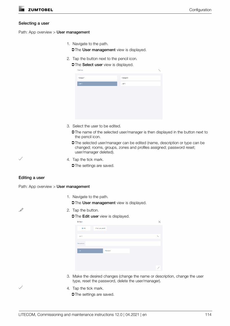
Configuration
LITECOM, Commissioning and maintenance instructions 12.0 | 04.2021 | en 114
Selecting a user
Path: App overview > User management
1. Navigate to the path.
ÜThe User management view is displayed.
2. Tap the button next to the pencil icon.
ÜThe Select user view is displayed.
3. Select the user to be edited.
ÜThe name of the selected user/manager is then displayed in the button next tothe pencil icon.
ÜThe selected user/manager can be edited (name, description or type can bechanged; rooms, groups, zones and profiles assigned; password reset;user/manager deleted).
4. Tap the tick mark.
ÜThe settings are saved.
Editing a user
Path: App overview > User management
1. Navigate to the path.
ÜThe User management view is displayed.
2. Tap the button.
ÜThe Edit user view is displayed.
3. Make the desired changes (change the name or description, change the usertype, reset the password, delete the user/manager).
4. Tap the tick mark.
ÜThe settings are saved.
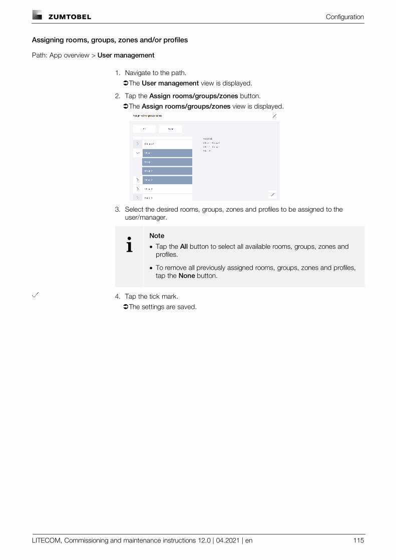
Configuration
LITECOM, Commissioning and maintenance instructions 12.0 | 04.2021 | en 115
Assigning rooms, groups, zones and/or profiles
Path: App overview > User management
1. Navigate to the path.
ÜThe User management view is displayed.
2. Tap the Assign rooms/groups/zones button.
ÜThe Assign rooms/groups/zones view is displayed.
3. Select the desired rooms, groups, zones and profiles to be assigned to theuser/manager.
iNote
· Tap the All button to select all available rooms, groups, zones andprofiles.
· To remove all previously assigned rooms, groups, zones and profiles,tap the None button.
4. Tap the tick mark.
ÜThe settings are saved.
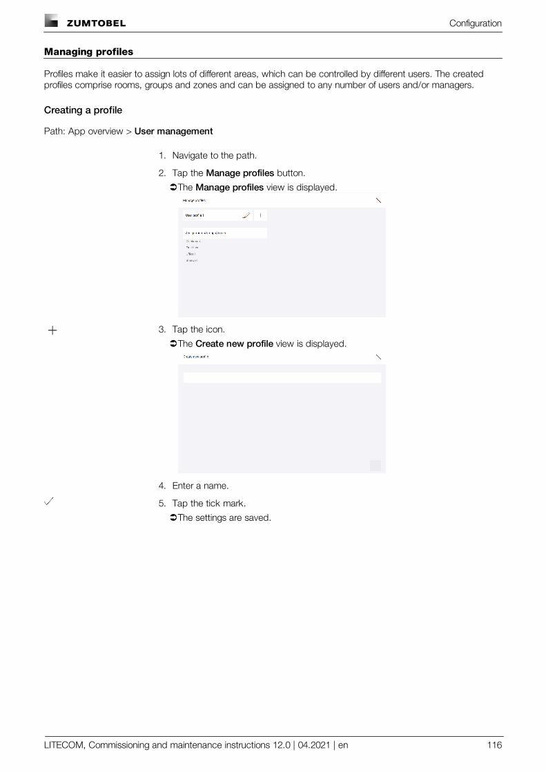
Configuration
LITECOM, Commissioning and maintenance instructions 12.0 | 04.2021 | en 116
Managing profiles
Profiles make it easier to assign lots of different areas, which can be controlled by different users. The createdprofiles comprise rooms, groups and zones and can be assigned to any number of users and/or managers.
Creating a profile
Path: App overview > User management
1. Navigate to the path.
2. Tap the Manage profiles button.
ÜThe Manage profiles view is displayed.
3. Tap the icon.
ÜThe Create new profile view is displayed.
4. Enter a name.
5. Tap the tick mark.
ÜThe settings are saved.
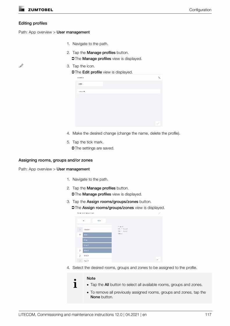
Configuration
LITECOM, Commissioning and maintenance instructions 12.0 | 04.2021 | en 117
Editing profiles
Path: App overview > User management
1. Navigate to the path.
2. Tap the Manage profiles button.
ÜThe Manage profiles view is displayed.
3. Tap the icon.
ÜThe Edit profile view is displayed.
4. Make the desired change (change the name, delete the profile).
5. Tap the tick mark.
ÜThe settings are saved.
Assigning rooms, groups and/or zones
Path: App overview > User management
1. Navigate to the path.
2. Tap the Manage profiles button.
ÜThe Manage profiles view is displayed.
3. Tap the Assign rooms/groups/zones button.
ÜThe Assign rooms/groups/zones view is displayed.
4. Select the desired rooms, groups and zones to be assigned to the profile.
iNote
· Tap the All button to select all available rooms, groups and zones.
· To remove all previously assigned rooms, groups and zones, tap the None button.
Configuration
LITECOM, Commissioning and maintenance instructions 12.0 | 04.2021 | en 118
5. Tap the tick mark.
ÜThe settings are saved.
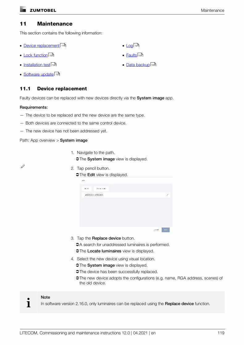
Maintenance
LITECOM, Commissioning and maintenance instructions 12.0 | 04.2021 | en 119
11 Maintenance
This section contains the following information:
· Device replacement
· Lock function
· Installation test
· Software update
· Log
· Faults
· Data backup
11.1 Device replacement
Faulty devices can be replaced with new devices directly via the System image app.
Requirements:
— The device to be replaced and the new device are the same type.
— Both devices are connected to the same control device.
— The new device has not been addressed yet.
Path: App overview > System image
1. Navigate to the path.
ÜThe System image view is displayed.
2. Tap pencil button.
ÜThe Edit view is displayed.
3. Tap the Replace device button.
ÜA search for unaddressed luminaires is performed.
ÜThe Locate luminaires view is displayed.
4. Select the new device using visual location.
ÜThe System image view is displayed.
ÜThe device has been successfully replaced.
ÜThe new device adopts the configurations (e.g. name, RGA address, scenes) ofthe old device.
iNote
In software version 2.16.0, only luminaires can be replaced using the Replace device function.
119
120
122
123
127
128
129
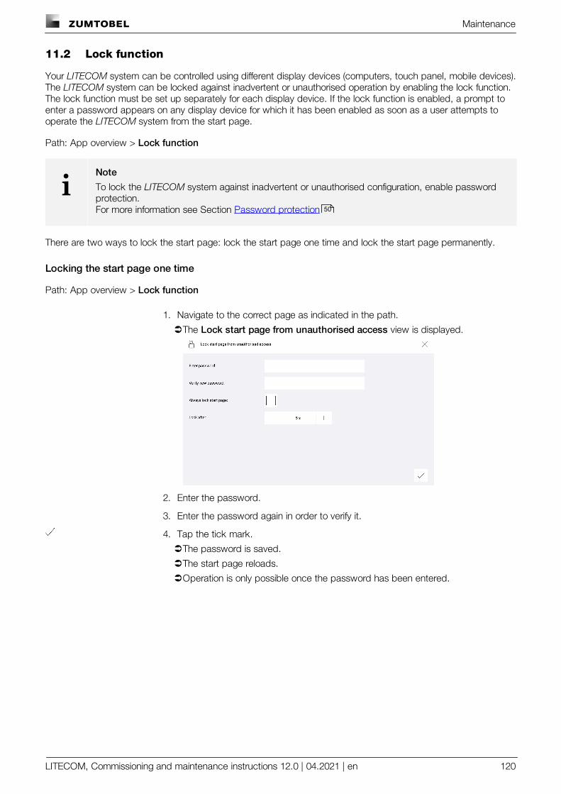
Maintenance
LITECOM, Commissioning and maintenance instructions 12.0 | 04.2021 | en 120
11.2 Lock function
Your LITECOM system can be controlled using different display devices (computers, touch panel, mobile devices).The LITECOM system can be locked against inadvertent or unauthorised operation by enabling the lock function.The lock function must be set up separately for each display device. If the lock function is enabled, a prompt toenter a password appears on any display device for which it has been enabled as soon as a user attempts tooperate the LITECOM system from the start page.
Path: App overview > Lock function
iNote
To lock the LITECOM system against inadvertent or unauthorised configuration, enable passwordprotection.For more information see Section Password protection
There are two ways to lock the start page: lock the start page one time and lock the start page permanently.
Locking the start page one time
Path: App overview > Lock function
1. Navigate to the correct page as indicated in the path.
ÜThe Lock start page from unauthorised access view is displayed.
2. Enter the password.
3. Enter the password again in order to verify it.
4. Tap the tick mark.
ÜThe password is saved.
ÜThe start page reloads.
ÜOperation is only possible once the password has been entered.
50
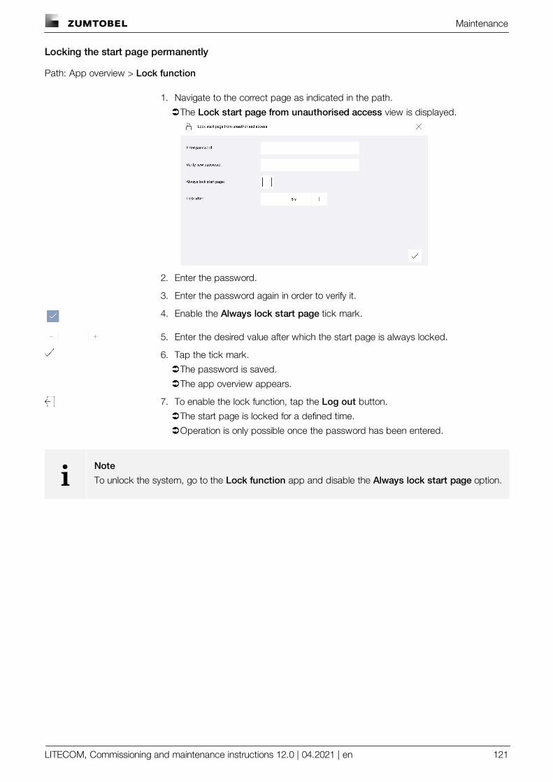
Maintenance
LITECOM, Commissioning and maintenance instructions 12.0 | 04.2021 | en 121
Locking the start page permanently
Path: App overview > Lock function
1. Navigate to the correct page as indicated in the path.
ÜThe Lock start page from unauthorised access view is displayed.
2. Enter the password.
3. Enter the password again in order to verify it.
4. Enable the Always lock start page tick mark.
5. Enter the desired value after which the start page is always locked.
6. Tap the tick mark.
ÜThe password is saved.
ÜThe app overview appears.
7. To enable the lock function, tap the Log out button.
ÜThe start page is locked for a defined time.
ÜOperation is only possible once the password has been entered.
iNote
To unlock the system, go to the Lock function app and disable the Always lock start page option.
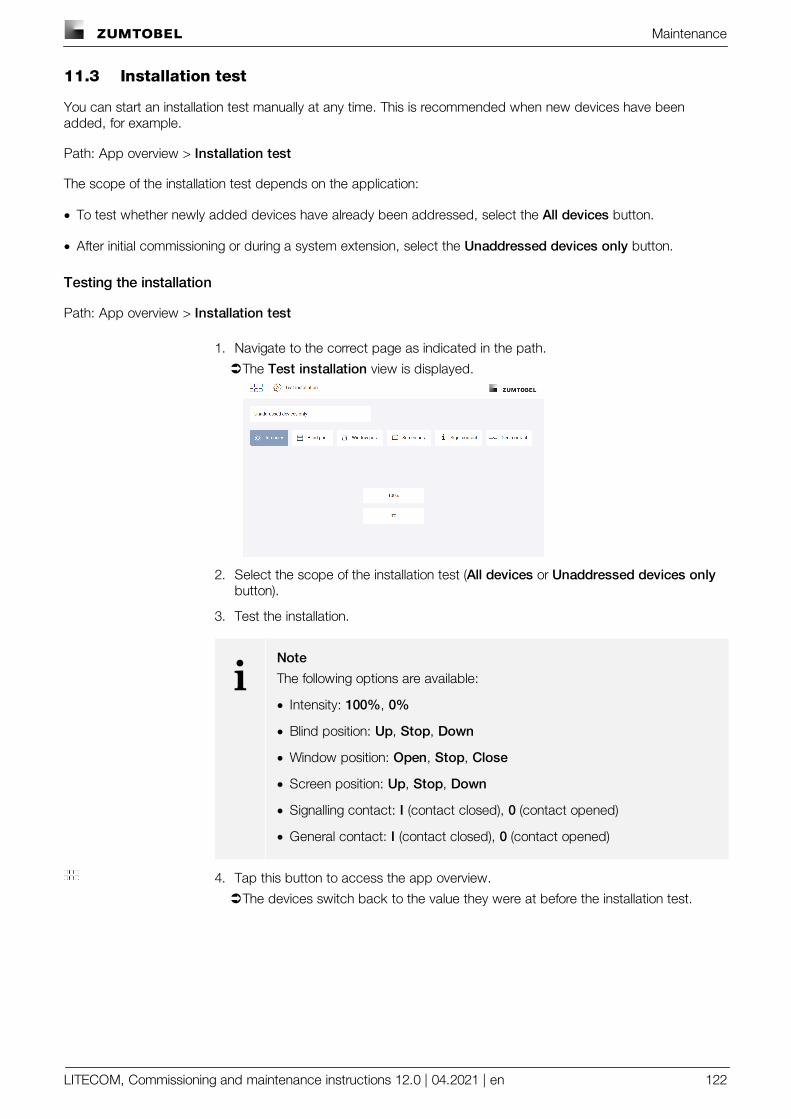
Maintenance
LITECOM, Commissioning and maintenance instructions 12.0 | 04.2021 | en 122
11.3 Installation test
You can start an installation test manually at any time. This is recommended when new devices have beenadded, for example.
Path: App overview > Installation test
The scope of the installation test depends on the application:
· To test whether newly added devices have already been addressed, select the All devices button.
· After initial commissioning or during a system extension, select the Unaddressed devices only button.
Testing the installation
Path: App overview > Installation test
1. Navigate to the correct page as indicated in the path.
ÜThe Test installation view is displayed.
2. Select the scope of the installation test (All devices or Unaddressed devices onlybutton).
3. Test the installation.
iNote
The following options are available:
· Intensity: 100%, 0%
· Blind position: Up, Stop, Down
· Window position: Open, Stop, Close
· Screen position: Up, Stop, Down
· Signalling contact: I (contact closed), 0 (contact opened)
· General contact: I (contact closed), 0 (contact opened)
4. Tap this button to access the app overview.
ÜThe devices switch back to the value they were at before the installation test.
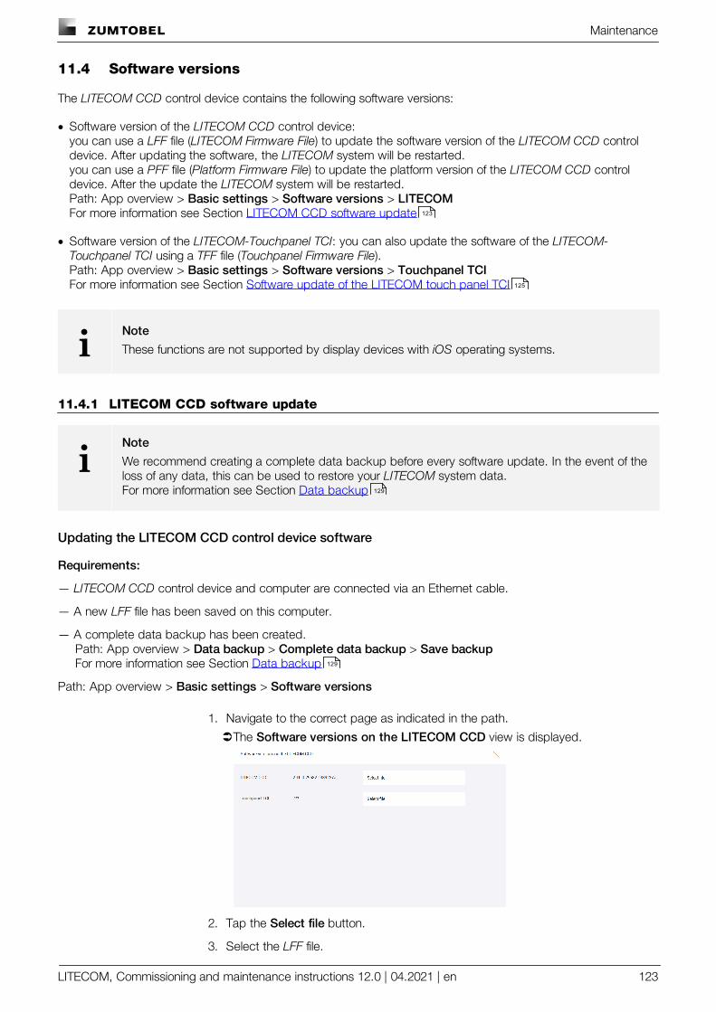
Maintenance
LITECOM, Commissioning and maintenance instructions 12.0 | 04.2021 | en 123
11.4 Software versions
The LITECOM CCD control device contains the following software versions:
· Software version of the LITECOM CCD control device: you can use a LFF file (LITECOM Firmware File) to update the software version of the LITECOM CCD controldevice. After updating the software, the LITECOM system will be restarted.you can use a PFF file (Platform Firmware File) to update the platform version of the LITECOM CCD controldevice. After the update the LITECOM system will be restarted.Path: App overview > Basic settings > Software versions > LITECOMFor more information see Section LITECOM CCD software update
· Software version of the LITECOM-Touchpanel TCI: you can also update the software of the LITECOM-Touchpanel TCI using a TFF file (Touchpanel Firmware File).Path: App overview > Basic settings > Software versions > Touchpanel TCIFor more information see Section Software update of the LITECOM touch panel TCI
iNote
These functions are not supported by display devices with iOS operating systems.
11.4.1 LITECOM CCD software update
iNote
We recommend creating a complete data backup before every software update. In the event of theloss of any data, this can be used to restore your LITECOM system data.For more information see Section Data backup
Updating the LITECOM CCD control device software
Requirements:
— LITECOM CCD control device and computer are connected via an Ethernet cable.
— A new LFF file has been saved on this computer.
— A complete data backup has been created.Path: App overview > Data backup > Complete data backup > Save backupFor more information see Section Data backup
Path: App overview > Basic settings > Software versions
1. Navigate to the correct page as indicated in the path.
ÜThe Software versions on the LITECOM CCD view is displayed.
2. Tap the Select file button.
3. Select the LFF file.
123
125
129
129
Maintenance
LITECOM, Commissioning and maintenance instructions 12.0 | 04.2021 | en 124
4. Tap the tick mark.
ÜA pop-up window with a progress bar appears.
ÜThe files for the software update are uploaded.
ÜThe software is updated.
ÜThe LITECOM CCD control device is restarted.
iNote
This process may take several minutes.
ÜAs soon as the software is updated, a corresponding message appears.
5. Tap the tick mark.
ÜThe start page appears.
iNote
Once the software has been successfully updated and you have connected to the web applicationwith another display device, a message appears, indicating that the web application interface mustbe reloaded due to a software update.
wConfirm the message.
ÜThe web application interface is reloaded.
ÜThe start page appears.
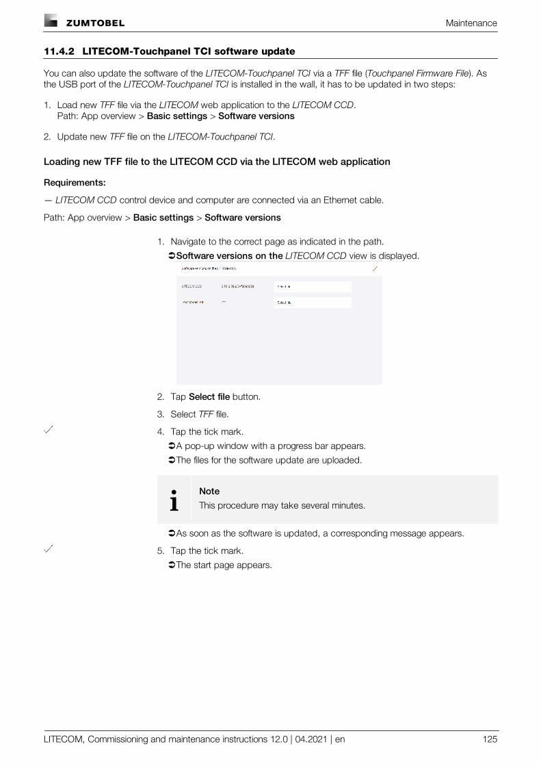
Maintenance
LITECOM, Commissioning and maintenance instructions 12.0 | 04.2021 | en 125
11.4.2 LITECOM-Touchpanel TCI software update
You can also update the software of the LITECOM-Touchpanel TCI via a TFF file (Touchpanel Firmware File). Asthe USB port of the LITECOM-Touchpanel TCI is installed in the wall, it has to be updated in two steps:
1. Load new TFF file via the LITECOM web application to the LITECOM CCD.Path: App overview > Basic settings > Software versions
2. Update new TFF file on the LITECOM-Touchpanel TCI.
Loading new TFF file to the LITECOM CCD via the LITECOM web application
Requirements:
— LITECOM CCD control device and computer are connected via an Ethernet cable.
Path: App overview > Basic settings > Software versions
1. Navigate to the correct page as indicated in the path.
ÜSoftware versions on the LITECOM CCD view is displayed.
2. Tap Select file button.
3. Select TFF file.
4. Tap the tick mark.
ÜA pop-up window with a progress bar appears.
ÜThe files for the software update are uploaded.
iNote
This procedure may take several minutes.
ÜAs soon as the software is updated, a corresponding message appears.
5. Tap the tick mark.
ÜThe start page appears.
Maintenance
LITECOM, Commissioning and maintenance instructions 12.0 | 04.2021 | en 126
Updating new TFF files on the LITECOM-Touchpanel TCI
Requirements:
— A new version of the LITECOM touch panel (TFF file) has already been loaded via the LITECOM webapplication onto the LITECOM CCD.Path: App overview > Basic settings > Software versions
— On the LITECOM-Touchpanel TCI, the start page of the LITECOM touch panel app is displayed.
1. Select Update app button.
ÜThe Update app view is displayed. Which version is currently on the LITECOM-Touchpanel TCI and whether an updated version is available, is shown.
2. If a more recent version is available, select Load from LITECOM CCD button.
ÜThe current version is downloaded from the LITECOM CCD; then the app isupdated automatically. This procedure may take several minutes.
3. Confirm that the application to be installed is replacing another application.
4. Confirm access rights to the app.
5. Tap Install button.
ÜThe app is installed and restarted automatically after the installation.
Maintenance
LITECOM, Commissioning and maintenance instructions 12.0 | 04.2021 | en 127
11.5 Log
General events as well as faults and warnings are logged in the Log app.
Path: App overview > Log
The following information is displayed for each event:
· Date and time: information about when the event occurred.
· Path: information about where the event occurred. If the event can be uniquely assigned to a device, the pathconsists of the room\group\device name, e.g. Room 1\Group 1\LIGHTS - 6400000100. All other events aremarked with application.
· Event: information on the type of event (Information, Error, Warning).
· Message: detailed information about the event
You can save the log as a CSV file. The save location depends on the browser settings.
iNote
This function is not supported by display devices with iOS operating systems.
Maintenance
LITECOM, Commissioning and maintenance instructions 12.0 | 04.2021 | en 128
11.6 Faults
The Faults app provides information on which field device faults are currently unresolved in your LITECOM systemat any given time.
Path: App overview > Faults
The following information is displayed for each fault:
· Date and time: information on when the fault occurred.
· Path: information on where the fault occurred. The path consists of the room\group\device name, e.g. Room1\Group 1\LIGHTS - 6400000100
· Type: Type of device assigned during addressing, e.g. Standard, Direct, Warm-white. This information isrequired above all for special luminaires, in order to determine the light source of the special luminaire for whichthe fault has occurred. The individual light sources for a special luminaire are summarised when specialluminaires are created. As soon as the special luminaire has been created, only the special luminaire isdisplayed in the system image; the light sources no longer appear individually.
· Message: information about the fault
As soon as a fault has been corrected the corresponding entry disappears from the list.
iNote
Messages about the occurrence and correction of faults can still be seen in the log.For more information see Section Log
You can also save a list of the current faults as a CSV file. The save location depends on the browser settings.
iNote
This function is not supported by display devices with iOS operating systems.
127
Maintenance
LITECOM, Commissioning and maintenance instructions 12.0 | 04.2021 | en 129
11.7 Data backup
It is possible to back up your LITECOM system data. In the event of the loss of any data, this can be used torestore your LITECOM system data.
iNote
This function is not supported by display devices with iOS operating systems.
Path: App overview > Data backup
There are two ways to back up your LITECOM system data: by creating a complete data backup or partial databackup.
Complete data backup Partial data backup
Save location On the computer or mobile device; savelocation depends on the browser settings.
Locally on the LITECOM CCD control device
Requirement The LITECOM CCD control device andcomputer or mobile device must beconnected via an Ethernet cable or wirelessaccess point.
–
File type LCP file (software version 1.3 and higher)
iNote
In software version 1.2 and lower,the data was saved in an LKP file.The data from LKP files can alsobe restored in LITECOM systemswith software version 1.3 andhigher. Device-specific settings forfield devices are not included inthese data backups, however.
–
Method of data backup Manual · Manual: six manual data backups can besaved. As soon as the seventh data backupis created, the oldest manual data backupis overwritten.
· Automatic: the data is automatically backedup every night. Three automatic databackups can be saved. As soon as thefourth data backup is created, the oldestautomatic data backup is overwritten.
Maintenance
LITECOM, Commissioning and maintenance instructions 12.0 | 04.2021 | en 130
Complete data backup Partial data backup
Scope of data backup · Configuration of the LITECOM system (e.g.system image, scenes, conditional scenerecall, presence linking)
· Device-specific settings for the DALI/eDfield devices, which are connected directlyto the LITECOM CCD and can beconfigured via LITECOM (exceptSEQUENCE infinity)
· DALI database for the LITECOM CCDcontrol device
· Configuration of the LITECOM system (e.g.system image, scenes, conditional scenerecall, presence linking)
· Device-specific settings for the DALI/eDfield devices, which are connected directlyto the LITECOM CCD and can beconfigured via LITECOM (exceptSEQUENCE infinity)
· DALI database for the LITECOM CCDcontrol device
iNote
If additional gateways are connected to the LITECOM CCD (e.g. LM-3DALIS), aseparate data backup must be created for each of these devices using theservice homepage in question.
· Partial data backups (if there are any)· Log· Password for locking against inadvertent or
unauthorised configuration· User-defined colours· All available images on the controls· Time zone
· Time zone
Area of application After successful commissioning the LITECOM CCD control device has to bereplaced so that the configuration can berestored.
Before a major reconfiguration; a previousversion of the configuration can be restored ifnecessary.
Table 73: Differences between data backups
iNote
The following settings are not saved:
· Browser-specific settings, e.g. language, password to protect against inadvertent or unauthorisedoperation (lock function), start page settings
· Control device-specific settings, e.g. licences
· Network settings, date, time
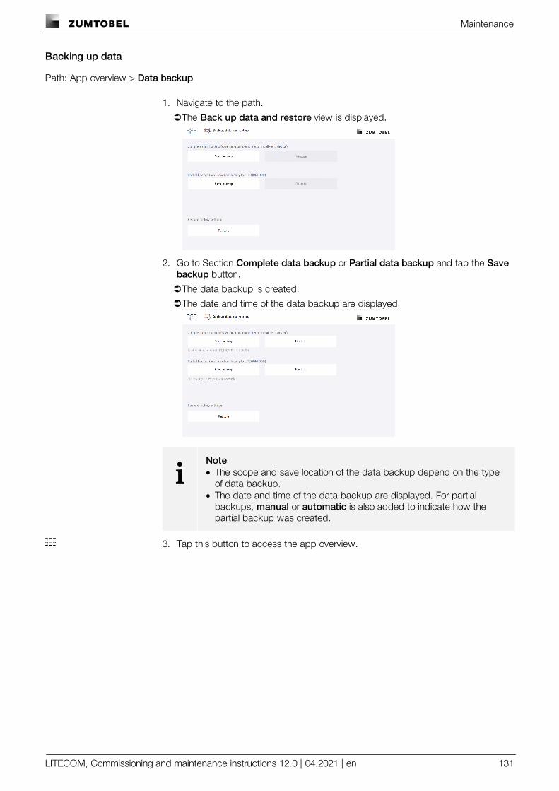
Maintenance
LITECOM, Commissioning and maintenance instructions 12.0 | 04.2021 | en 131
Backing up data
Path: App overview > Data backup
1. Navigate to the path.
ÜThe Back up data and restore view is displayed.
2. Go to Section Complete data backup or Partial data backup and tap the Savebackup button.
ÜThe data backup is created.
ÜThe date and time of the data backup are displayed.
iNote· The scope and save location of the data backup depend on the type
of data backup.· The date and time of the data backup are displayed. For partial
backups, manual or automatic is also added to indicate how thepartial backup was created.
3. Tap this button to access the app overview.
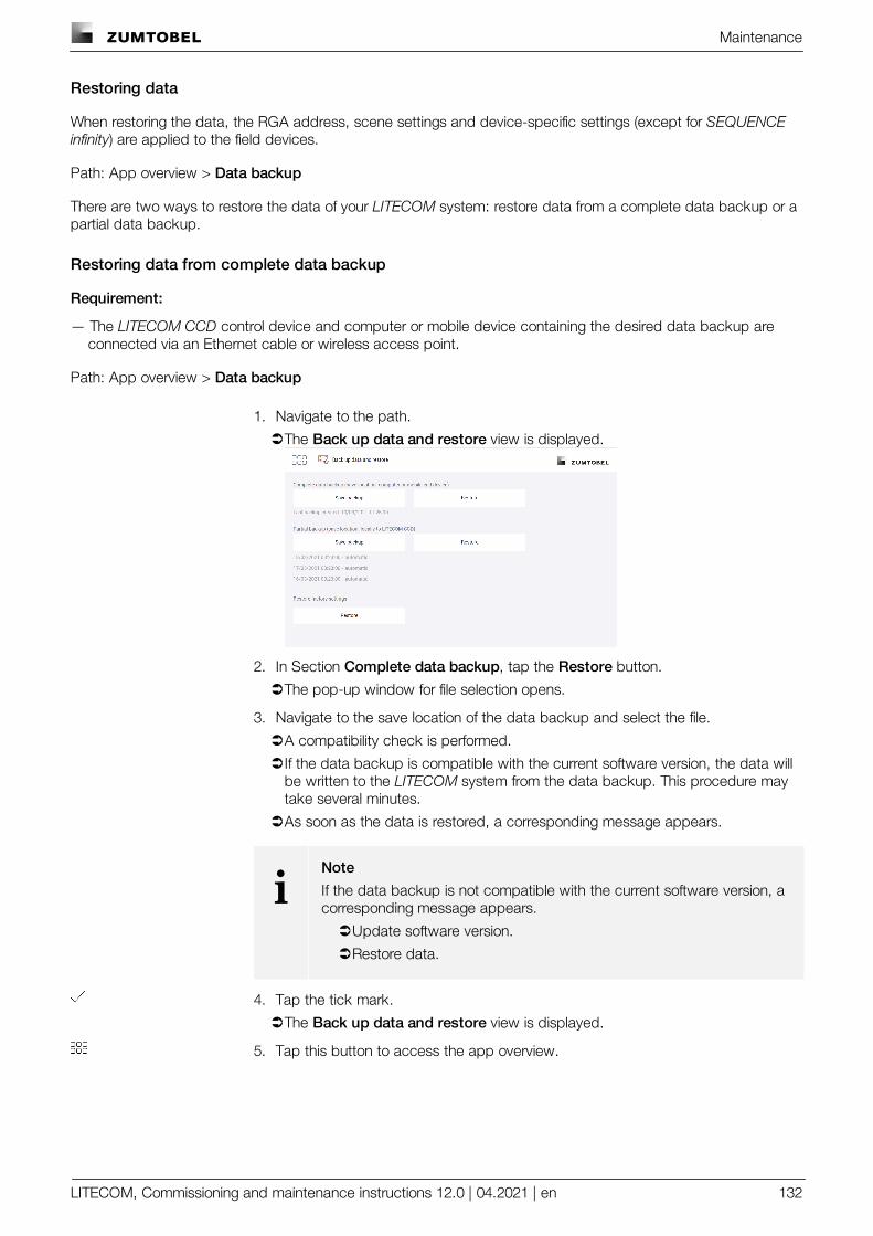
Maintenance
LITECOM, Commissioning and maintenance instructions 12.0 | 04.2021 | en 132
Restoring data
When restoring the data, the RGA address, scene settings and device-specific settings (except for SEQUENCEinfinity) are applied to the field devices.
Path: App overview > Data backup
There are two ways to restore the data of your LITECOM system: restore data from a complete data backup or apartial data backup.
Restoring data from complete data backup
Requirement:
— The LITECOM CCD control device and computer or mobile device containing the desired data backup areconnected via an Ethernet cable or wireless access point.
Path: App overview > Data backup
1. Navigate to the path.
ÜThe Back up data and restore view is displayed.
2. In Section Complete data backup, tap the Restore button.
ÜThe pop-up window for file selection opens.
3. Navigate to the save location of the data backup and select the file.
ÜA compatibility check is performed.
ÜIf the data backup is compatible with the current software version, the data willbe written to the LITECOM system from the data backup. This procedure maytake several minutes.
ÜAs soon as the data is restored, a corresponding message appears.
iNote
If the data backup is not compatible with the current software version, acorresponding message appears.
ÜUpdate software version.
ÜRestore data.
4. Tap the tick mark.
ÜThe Back up data and restore view is displayed.
5. Tap this button to access the app overview.
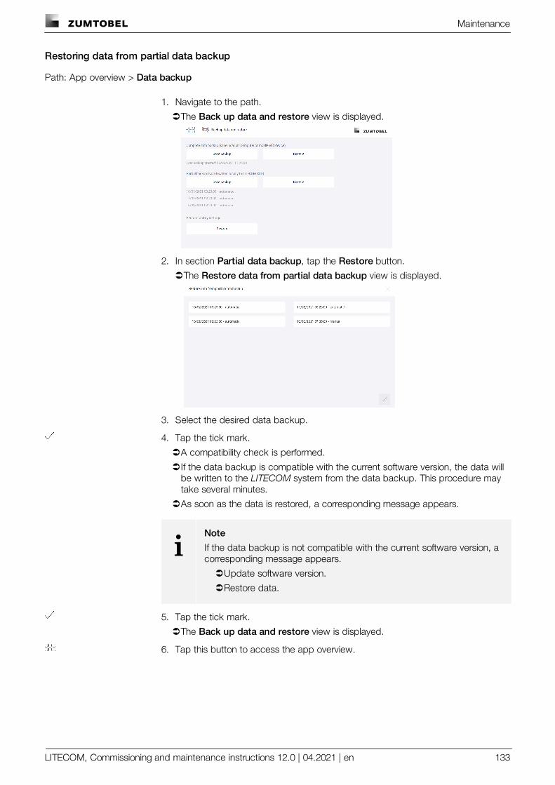
Maintenance
LITECOM, Commissioning and maintenance instructions 12.0 | 04.2021 | en 133
Restoring data from partial data backup
Path: App overview > Data backup
1. Navigate to the path.
ÜThe Back up data and restore view is displayed.
2. In section Partial data backup, tap the Restore button.
ÜThe Restore data from partial data backup view is displayed.
3. Select the desired data backup.
4. Tap the tick mark.
ÜA compatibility check is performed.
ÜIf the data backup is compatible with the current software version, the data willbe written to the LITECOM system from the data backup. This procedure maytake several minutes.
ÜAs soon as the data is restored, a corresponding message appears.
iNote
If the data backup is not compatible with the current software version, acorresponding message appears.
ÜUpdate software version.
ÜRestore data.
5. Tap the tick mark.
ÜThe Back up data and restore view is displayed.
6. Tap this button to access the app overview.
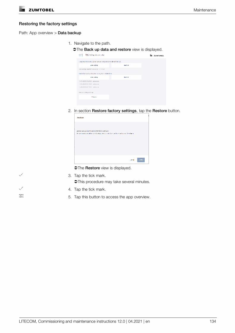
Maintenance
LITECOM, Commissioning and maintenance instructions 12.0 | 04.2021 | en 134
Restoring the factory settings
Path: App overview > Data backup
1. Navigate to the path.
ÜThe Back up data and restore view is displayed.
2. In section Restore factory settings, tap the Restore button.
ÜThe Restore view is displayed.
3. Tap the tick mark.
ÜThis procedure may take several minutes.
4. Tap the tick mark.
5. Tap this button to access the app overview.
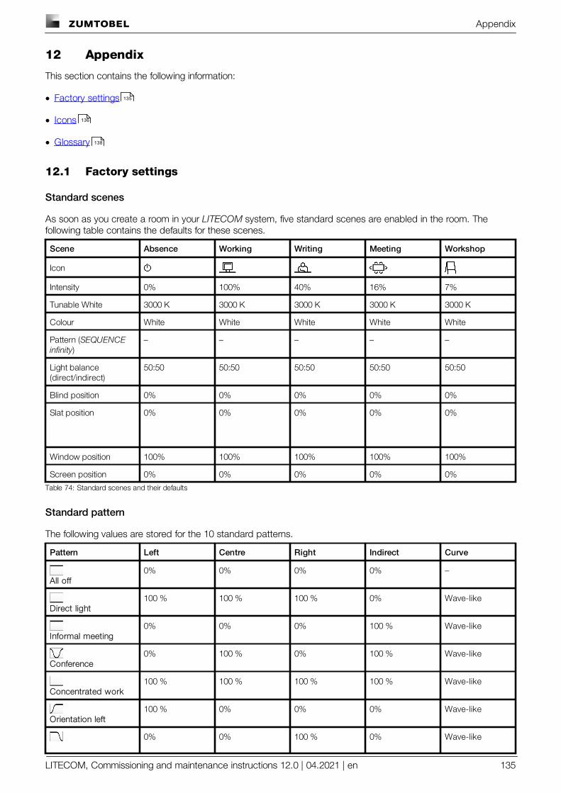
Appendix
LITECOM, Commissioning and maintenance instructions 12.0 | 04.2021 | en 135
12 Appendix
This section contains the following information:
· Factory settings
· Icons
· Glossary
12.1 Factory settings
Standard scenes
As soon as you create a room in your LITECOM system, five standard scenes are enabled in the room. Thefollowing table contains the defaults for these scenes.
Scene Absence Working Writing Meeting Workshop
Icon
Intensity 0% 100% 40% 16% 7%
Tunable White 3000 K 3000 K 3000 K 3000 K 3000 K
Colour White White White White White
Pattern (SEQUENCEinfinity)
– – – – –
Light balance(direct/indirect)
50:50 50:50 50:50 50:50 50:50
Blind position 0% 0% 0% 0% 0%
Slat position 0% 0% 0% 0% 0%
Window position 100% 100% 100% 100% 100%
Screen position 0% 0% 0% 0% 0%
Table 74: Standard scenes and their defaults
Standard pattern
The following values are stored for the 10 standard patterns.
Pattern Left Centre Right Indirect Curve
All off0% 0% 0% 0% –
Direct light100 % 100 % 100 % 0% Wave-like
Informal meeting0% 0% 0% 100 % Wave-like
Conference0% 100 % 0% 100 % Wave-like
Concentrated work100 % 100 % 100 % 100 % Wave-like
Orientation left100 % 0% 0% 0% Wave-like
0% 0% 100 % 0% Wave-like
135
136
138
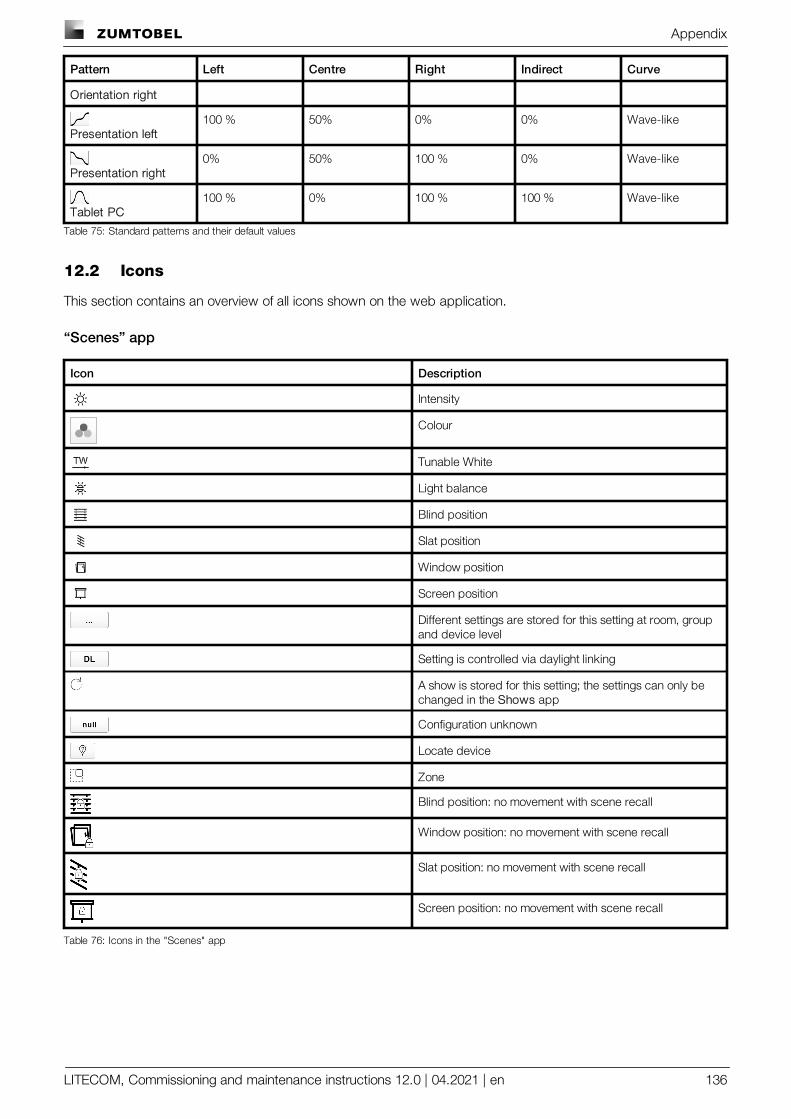
Appendix
LITECOM, Commissioning and maintenance instructions 12.0 | 04.2021 | en 136
Pattern Left Centre Right Indirect Curve
Orientation right
Presentation left100 % 50% 0% 0% Wave-like
Presentation right0% 50% 100 % 0% Wave-like
Tablet PC100 % 0% 100 % 100 % Wave-like
Table 75: Standard patterns and their default values
12.2 Icons
This section contains an overview of all icons shown on the web application.
“Scenes” app
Icon Description
Intensity
Colour
Tunable White
Light balance
Blind position
Slat position
Window position
Screen position
Different settings are stored for this setting at room, groupand device level
Setting is controlled via daylight linking
A show is stored for this setting; the settings can only bechanged in the Shows app
Configuration unknown
Locate device
Zone
Blind position: no movement with scene recall
Window position: no movement with scene recall
Slat position: no movement with scene recall
Screen position: no movement with scene recall
Table 76: Icons in the "Scenes" app
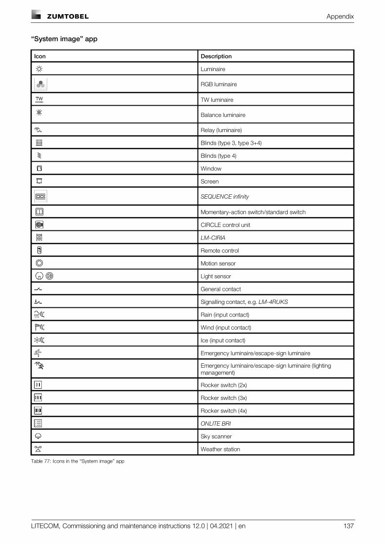
Appendix
LITECOM, Commissioning and maintenance instructions 12.0 | 04.2021 | en 137
“System image” app
Icon Description
Luminaire
RGB luminaire
TW luminaire
Balance luminaire
Relay (luminaire)
Blinds (type 3, type 3+4)
Blinds (type 4)
Window
Screen
SEQUENCE infinity
Momentary-action switch/standard switch
CIRCLE control unit
LM-CIRIA
Remote control
Motion sensor
Light sensor
General contact
Signalling contact, e.g. LM-4RUKS
Rain (input contact)
Wind (input contact)
Ice (input contact)
Emergency luminaire/escape-sign luminaire
Emergency luminaire/escape-sign luminaire (lightingmanagement)
Rocker switch (2x)
Rocker switch (3x)
Rocker switch (4x)
ONLITE BRI
Sky scanner
Weather station
Table 77: Icons in the “System image” app
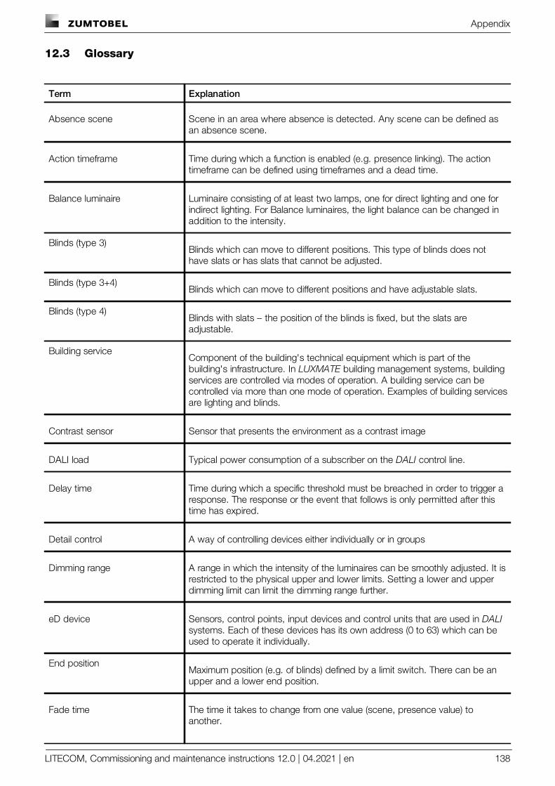
Appendix
LITECOM, Commissioning and maintenance instructions 12.0 | 04.2021 | en 138
12.3 Glossary
Term Explanation
Absence scene Scene in an area where absence is detected. Any scene can be defined asan absence scene.
Action timeframe Time during which a function is enabled (e.g. presence linking). The actiontimeframe can be defined using timeframes and a dead time.
Balance luminaire Luminaire consisting of at least two lamps, one for direct lighting and one forindirect lighting. For Balance luminaires, the light balance can be changed inaddition to the intensity.
Blinds (type 3)Blinds which can move to different positions. This type of blinds does nothave slats or has slats that cannot be adjusted.
Blinds (type 3+4)Blinds which can move to different positions and have adjustable slats.
Blinds (type 4)Blinds with slats – the position of the blinds is fixed, but the slats areadjustable.
Building serviceComponent of the building's technical equipment which is part of thebuilding's infrastructure. In LUXMATE building management systems, buildingservices are controlled via modes of operation. A building service can becontrolled via more than one mode of operation. Examples of building servicesare lighting and blinds.
Contrast sensor Sensor that presents the environment as a contrast image
DALI load Typical power consumption of a subscriber on the DALI control line.
Delay time Time during which a specific threshold must be breached in order to trigger aresponse. The response or the event that follows is only permitted after thistime has expired.
Detail control A way of controlling devices either individually or in groups
Dimming range A range in which the intensity of the luminaires can be smoothly adjusted. It isrestricted to the physical upper and lower limits. Setting a lower and upperdimming limit can limit the dimming range further.
eD device Sensors, control points, input devices and control units that are used in DALIsystems. Each of these devices has its own address (0 to 63) which can beused to operate it individually.
End positionMaximum position (e.g. of blinds) defined by a limit switch. There can be anupper and a lower end position.
Fade time The time it takes to change from one value (scene, presence value) toanother.
Appendix
LITECOM, Commissioning and maintenance instructions 12.0 | 04.2021 | en 139
Term Explanation
Example with a scene as a value: If the fade time is, for example, 0 seconds,the change from one scene to the next is immediate. If the fade time is 20seconds, the outputs will smoothly adjust to gradually switch to the controlvalues for the next scene within those 20 seconds. All outputs reach thedesired value simultaneously (once the fade time has expired).
Ice alarmThe ice alarm should stop blinds from moving when ice has formed on them,preventing them from being damaged. It is triggered when the outdoortemperature drops below a certain threshold and a rain sensor has detectedprecipitation.
Light balance Ratio of direct to indirect lighting
Light source System for generating light in a luminaire (e.g. lamp, LED module)
Location Process for determining where a network or bus subscriber is located or whatits address it. How subscribers are located differs from device to device.There are three methods of locating devices: visual, acoustic and tactile.
Mode of operationDetermines which building service is being controlled. Each building service iscontrolled by at least one mode of operation. Examples of modes of operationare intensity, blind position and slat position.
Momentary-action switch (MAS) Control point that upon being operated either closes and/or opens a circuit,depending on its wiring, but without “clicking” into place like a standardswitch, i.e. once it is released the affected circuit returns to its original state.
Movement rangeDefines the capabilities of blinds or a window to move between the endpositions, if the blinds/window have an actuator which is able to measure thedistance covered and send feedback about the current position of theblinds/window. Setting a lower and upper limit of the movement range canlimit the range further.
PatternPreset control values for 3 or 4 DALI short SEQUENCE infinity addresses,through which activity-related light distributions are created (e.g. concentratedwork, presentation, conference)
Presence linking A way of controlling luminaires whilst taking into account the presence ofpeople. Presence is usually detected by presence detectors.
Presence scene Scene in an area where the presence of at least one person is detected. Anyscene can be defined as a presence scene.
Production numberGlobally unique identification number of a LUXMATE device. The serialnumber can be determined from the production number.
Rain alarmThe rain alarm should prevent blinds (such as awnings) from being damagedby rain. It is triggered after a rain sensor determines that a definedprecipitation level has been exceeded during a specified delay time.
Reference numberNumber used to generate and check the licence number.
Appendix
LITECOM, Commissioning and maintenance instructions 12.0 | 04.2021 | en 140
Term Explanation
Required illuminance Illuminance required at minimum at a specific location (e.g. workspace) sothat a person can complete visual tasks effectively and accurately.
RGA address Address used in LUXMATE systems for communication purposes. The RGAaddress is based on the following address scheme: room address/groupaddress/individual address.
RGB luminaire Luminaire consisting of three individual lamps (red, green, blue). Coloured lightis generated through additive colour mixing.
Run-on time Time that starts after a certain event (e.g. the last person leaves the room)and after which an action is triggered (e.g. fade time starts, absence scene isrecalled). If an event occurs during the run-on time (e.g. someone re-entersthe room), the run-on time starts again. A typical application for run-on time isthe stairwell function.
Slat positionSpecifies how the slats of blinds tilt. Expressed as a percentage (%).
Special luminaire Luminaire with multiple light sources (such as lamps, LED modules). The LITECOM web application can be used to combine the light sources into oneluminaire so that they can be controlled together.
Standard switch Control point that upon being operated either closes or opens a circuit and“clicks” into place as it does so (as opposed to a momentary-action switch).
System extension Process during which new network or bus subscribers are addressed, whichare used in an existing and addressed system. Addressing for previouslyaddressed network or bus subscribers will remain unchanged.
Timeframe Limited time period between two or more events which already have settimes.
Example: two timeframes are defined for presence linking (07:00–12:00 and14:00–18:00). Presence linking is enabled during these timeframes.
Tunable White Option of dynamically changing the light of the LED in the white light range.Colour temperatures from 2700 K to 6500 K, for example, can be variably setusing a control. The LED luminaires achieve high colour rendering of at leastRa 80 to Ra 90.
TW luminaire Luminaire that supports Tunable White pursuant to IEC 62386-209. There aretwo types of TW luminaire:
· Luminaires that consist of at least two individual lamps, one for warm-whiteand one for cool-white.
· Luminaires that have one individual lamp that supports Tunable White.
Visual location Type of location in which the address of a network or bus subscriber is usedto visually locate this subscriber in the field.
· A visually located luminaire, for example, responds by switching to themaximum level.
Appendix
LITECOM, Commissioning and maintenance instructions 12.0 | 04.2021 | en 141
Term Explanation
· A visually located set of blinds, for example, responds by moving to thelower end position.
Wind alarmThe wind alarm should stop blinds from moving when wind speeds are high,for example, preventing them from being damaged. It is triggered after a windspeed sensor determines that a defined wind speed has been exceededduring a specified delay time.
zumtobel.com/contact
EN 04/2020 © Zumtobel Lighting GmbH
T H E L I G H T
Integrated lighting solutions
Lighting and emergency systems
Controls and sensors
Technical and financial services
Digitalservices