Embed Size (px)
Citation preview
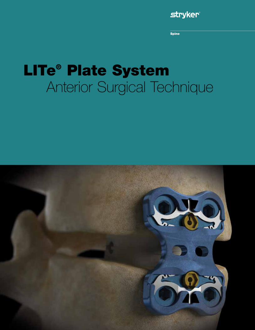
LITe® Plate System Anterior Surgical Technique
LITe Plate System Anterior Surgical Technique
2
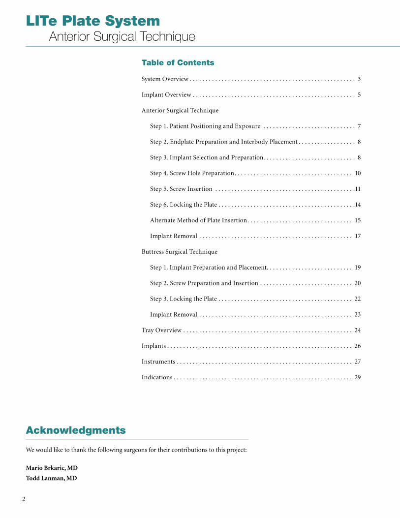
Table of Contents
System Overview . . . . . . . . . . . . . . . . . . . . . . . . . . . . . . . . . . . . . . . . . . . . . . . . . . . . 3
Implant Overview . . . . . . . . . . . . . . . . . . . . . . . . . . . . . . . . . . . . . . . . . . . . . . . . . . . 5
Anterior Surgical Technique
Step 1 . Patient Positioning and Exposure . . . . . . . . . . . . . . . . . . . . . . . . . . . . . 7
Step 2 . Endplate Preparation and Interbody Placement . . . . . . . . . . . . . . . . . . 8
Step 3 . Implant Selection and Preparation . . . . . . . . . . . . . . . . . . . . . . . . . . . . . 8
Step 4 . Screw Hole Preparation . . . . . . . . . . . . . . . . . . . . . . . . . . . . . . . . . . . . . 10
Step 5 . Screw Insertion . . . . . . . . . . . . . . . . . . . . . . . . . . . . . . . . . . . . . . . . . . . .11
Step 6 . Locking the Plate . . . . . . . . . . . . . . . . . . . . . . . . . . . . . . . . . . . . . . . . . . .14
Alternate Method of Plate Insertion . . . . . . . . . . . . . . . . . . . . . . . . . . . . . . . . . 15
Implant Removal . . . . . . . . . . . . . . . . . . . . . . . . . . . . . . . . . . . . . . . . . . . . . . . . 17
Buttress Surgical Technique
Step 1 . Implant Preparation and Placement . . . . . . . . . . . . . . . . . . . . . . . . . . . 19
Step 2 . Screw Preparation and Insertion . . . . . . . . . . . . . . . . . . . . . . . . . . . . . 20
Step 3 . Locking the Plate . . . . . . . . . . . . . . . . . . . . . . . . . . . . . . . . . . . . . . . . . . 22
Implant Removal . . . . . . . . . . . . . . . . . . . . . . . . . . . . . . . . . . . . . . . . . . . . . . . . 23
Tray Overview . . . . . . . . . . . . . . . . . . . . . . . . . . . . . . . . . . . . . . . . . . . . . . . . . . . . . 24
Implants . . . . . . . . . . . . . . . . . . . . . . . . . . . . . . . . . . . . . . . . . . . . . . . . . . . . . . . . . . 26
Instruments . . . . . . . . . . . . . . . . . . . . . . . . . . . . . . . . . . . . . . . . . . . . . . . . . . . . . . . 27
Indications . . . . . . . . . . . . . . . . . . . . . . . . . . . . . . . . . . . . . . . . . . . . . . . . . . . . . . . . 29
Acknowledgments
We would like to thank the following surgeons for their contributions to this project:
Mario Brkaric, MD
Todd Lanman, MD
3
LITe Plate System Anterior Surgical Technique
System Overview
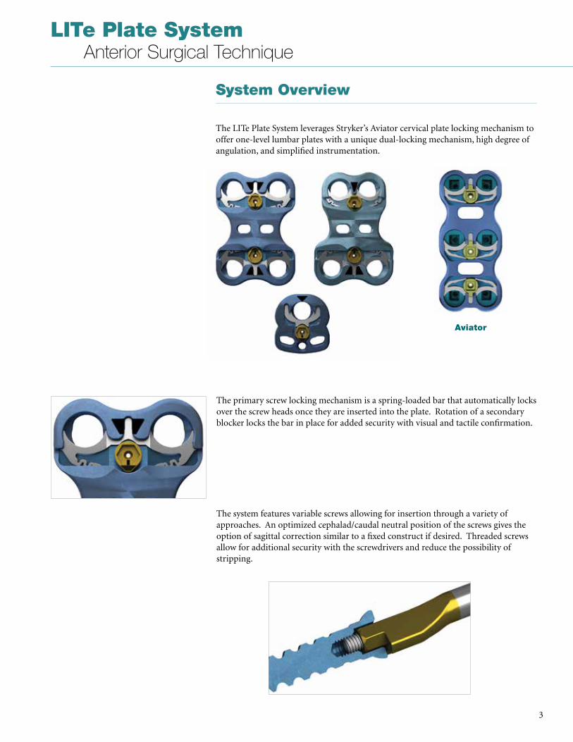
The LITe Plate System leverages Stryker’s Aviator cervical plate locking mechanism to offer one-level lumbar plates with a unique dual-locking mechanism, high degree of angulation, and simplified instrumentation .
The primary screw locking mechanism is a spring-loaded bar that automatically locks over the screw heads once they are inserted into the plate . Rotation of a secondary blocker locks the bar in place for added security with visual and tactile confirmation .
The system features variable screws allowing for insertion through a variety of approaches . An optimized cephalad/caudal neutral position of the screws gives the option of sagittal correction similar to a fixed construct if desired . Threaded screws allow for additional security with the screwdrivers and reduce the possibility of stripping .
Aviator
LITe Plate System Anterior Surgical Technique
4
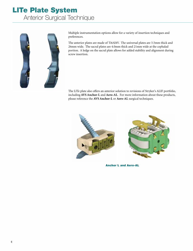
Multiple instrumentation options allow for a variety of insertion techniques and preferences .
The anterior plates are made of Ti6Al4V . The universal plates are 3 .5mm thick and 26mm wide . The sacral plates are 4 .0mm thick and 21mm wide at the cephalad portion . A ledge on the sacral plate allows for added stability and alignment during screw insertion .
The LITe plate also offers an anterior solution to revisions of Stryker’s ALIF portfolio, including AVS Anchor-L and Aero-AL . For more information about these products, please reference the AVS Anchor-L or Aero-AL surgical techniques .
Anchor L and Aero-AL
5
LITe Plate System Anterior Surgical Technique
Implant Overview
Plates
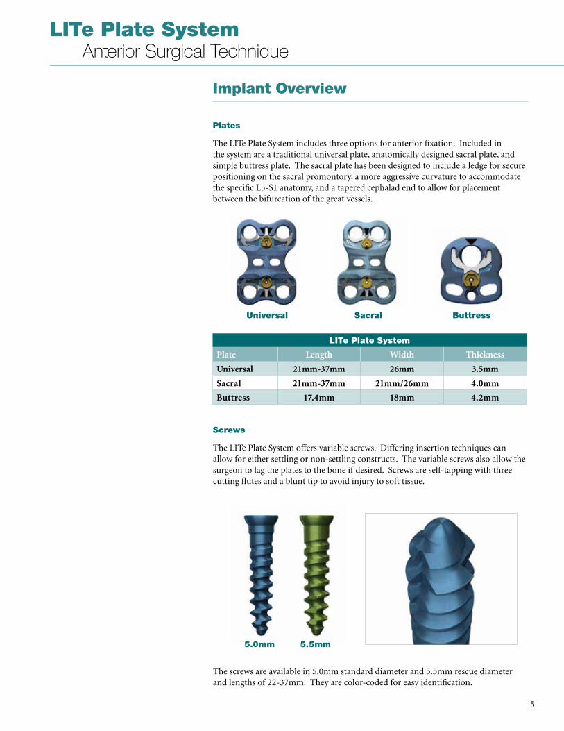
The LITe Plate System includes three options for anterior fixation . Included in the system are a traditional universal plate, anatomically designed sacral plate, and simple buttress plate . The sacral plate has been designed to include a ledge for secure positioning on the sacral promontory, a more aggressive curvature to accommodate the specific L5-S1 anatomy, and a tapered cephalad end to allow for placement between the bifurcation of the great vessels .
Screws
The LITe Plate System offers variable screws . Differing insertion techniques can allow for either settling or non-settling constructs . The variable screws also allow the surgeon to lag the plates to the bone if desired . Screws are self-tapping with three cutting flutes and a blunt tip to avoid injury to soft tissue .
LITe Plate System
Plate Length Width Thickness
Universal 21mm-37mm 26mm 3.5mm
Sacral 21mm-37mm 21mm/26mm 4.0mm
Buttress 17.4mm 18mm 4.2mm
The screws are available in 5 .0mm standard diameter and 5 .5mm rescue diameter and lengths of 22-37mm . They are color-coded for easy identification .
Universal Sacral Buttress
5.0mm 5.5mm
LITe Plate System Anterior Surgical Technique
6
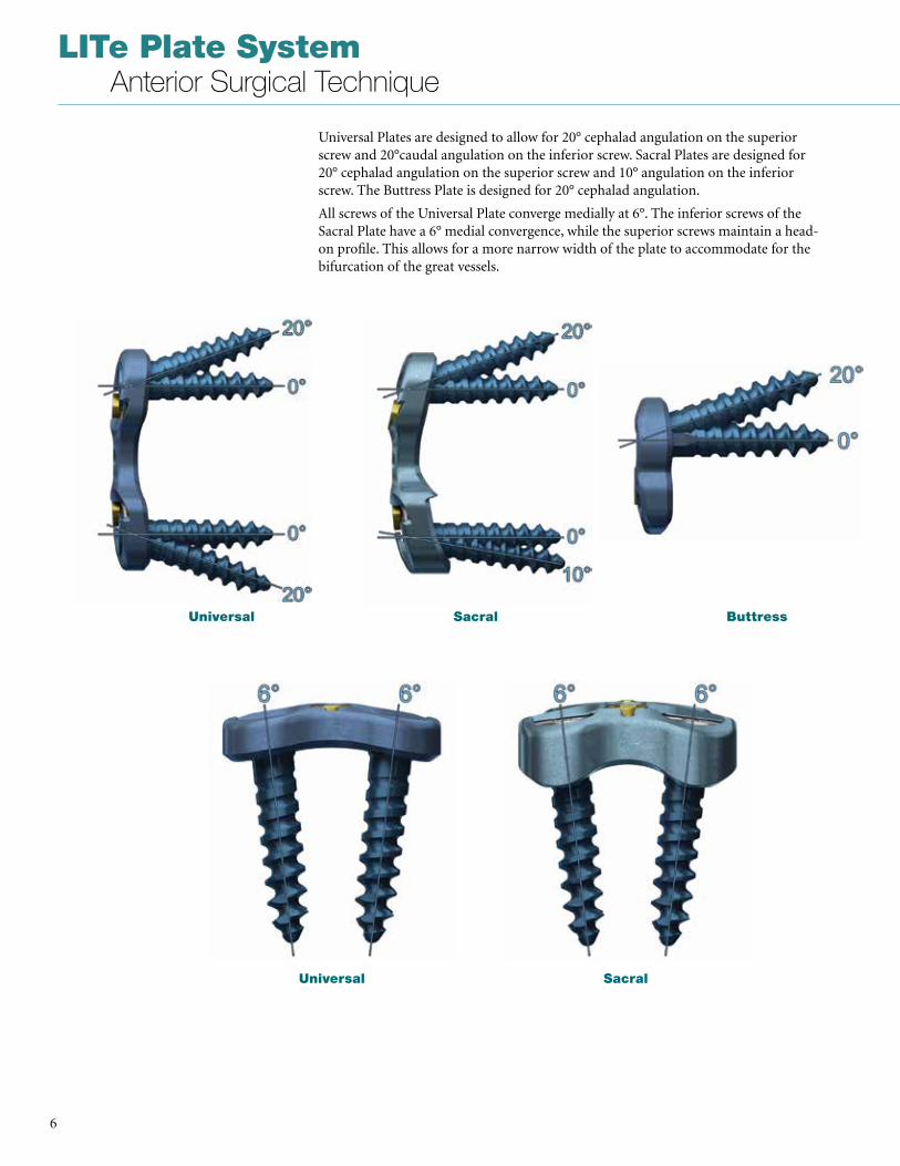
Universal Plates are designed to allow for 20° cephalad angulation on the superior screw and 20°caudal angulation on the inferior screw . Sacral Plates are designed for 20° cephalad angulation on the superior screw and 10° angulation on the inferior screw . The Buttress Plate is designed for 20° cephalad angulation .
All screws of the Universal Plate converge medially at 6° . The inferior screws of the Sacral Plate have a 6° medial convergence, while the superior screws maintain a head-on profile . This allows for a more narrow width of the plate to accommodate for the bifurcation of the great vessels .
Universal Sacral Buttress
Universal Sacral
7
LITe Plate System Anterior Surgical Technique
Step 1. Patient Positioning and Exposure
Determine surgical approach (transperitoneal or retroperitoneal).
The Stryker Reliance AL Instruments can be used in either a transperitoneal or retroperitoneal approach to the lumbosacral spine and may depend on which level of the spine is being treated . This technique details a retroperitoneal approach .
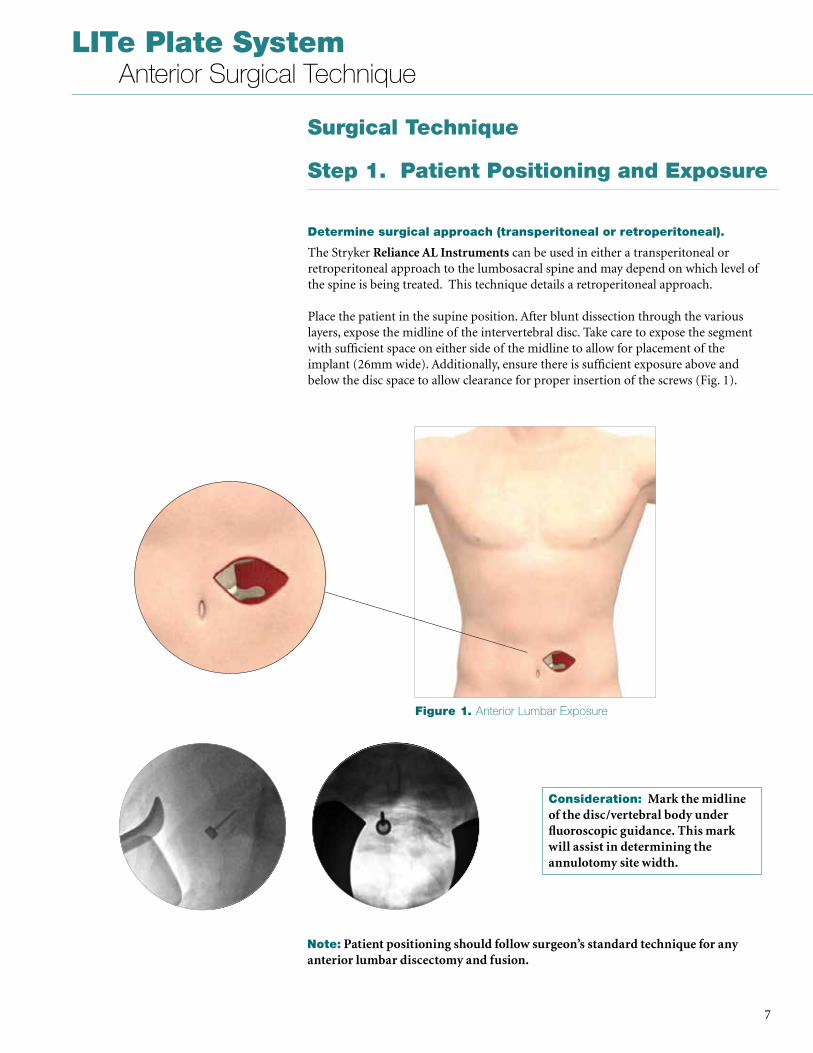
Place the patient in the supine position . After blunt dissection through the various layers, expose the midline of the intervertebral disc . Take care to expose the segment with sufficient space on either side of the midline to allow for placement of the implant (26mm wide) . Additionally, ensure there is sufficient exposure above and below the disc space to allow clearance for proper insertion of the screws (Fig . 1) .
Consideration: Mark the midline of the disc/vertebral body under fluoroscopic guidance. This mark will assist in determining the annulotomy site width.
Note: Patient positioning should follow surgeon’s standard technique for any anterior lumbar discectomy and fusion.
Surgical Technique
Figure 1. Anterior Lumbar Exposure
LITe Plate System Anterior Surgical Technique
8
Step 2. Endplate Preparation and Interbody Placement
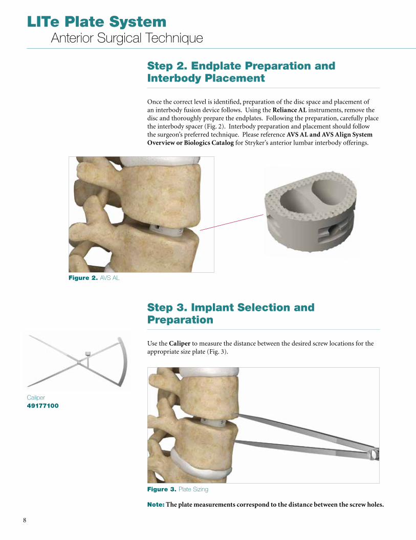
Once the correct level is identified, preparation of the disc space and placement of an interbody fusion device follows . Using the Reliance AL instruments, remove the disc and thoroughly prepare the endplates . Following the preparation, carefully place the interbody spacer (Fig . 2) . Interbody preparation and placement should follow the surgeon’s preferred technique . Please reference AVS AL and AVS Align System Overview or Biologics Catalog for Stryker’s anterior lumbar interbody offerings .
Caliper49177100
Step 3. Implant Selection and Preparation
Use the Caliper to measure the distance between the desired screw locations for the appropriate size plate (Fig . 3) .
Note: The plate measurements correspond to the distance between the screw holes.
Figure 2. AVS AL
Figure 3. Plate Sizing
9
LITe Plate System Anterior Surgical Technique
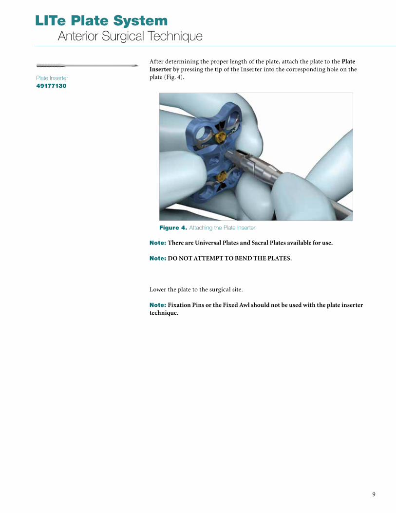
After determining the proper length of the plate, attach the plate to the Plate Inserter by pressing the tip of the Inserter into the corresponding hole on the plate (Fig . 4) .Plate Inserter
49177130
Note: There are Universal Plates and Sacral Plates available for use.
Note: DO NOT ATTEMPT TO BEND THE PLATES.
Lower the plate to the surgical site .
Note: Fixation Pins or the Fixed Awl should not be used with the plate inserter technique.
Figure 4. Attaching the Plate Inserter
LITe Plate System Anterior Surgical Technique
10
Step 4. Screw Hole Preparation
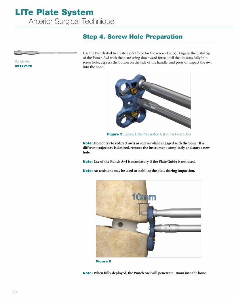
Use the Punch Awl to create a pilot hole for the screw (Fig . 5) . Engage the distal tip of the Punch Awl with the plate using downward force until the tip seats fully into screw hole, depress the button on the side of the handle, and press or impact the Awl into the bone .
Punch Awl49177170
Note: Do not try to redirect awls or screws while engaged with the bone. If a different trajectory is desired, remove the instrument completely and start a new hole.
Note: Use of the Punch Awl is mandatory if the Plate Guide is not used.
Note: An assistant may be used to stabilize the plate during impaction.
Note: When fully deployed, the Punch Awl will penetrate 10mm into the bone.
Figure 5. Screw Hole Preparation Using the Punch Awl
Figure 6
11
LITe Plate System Anterior Surgical Technique
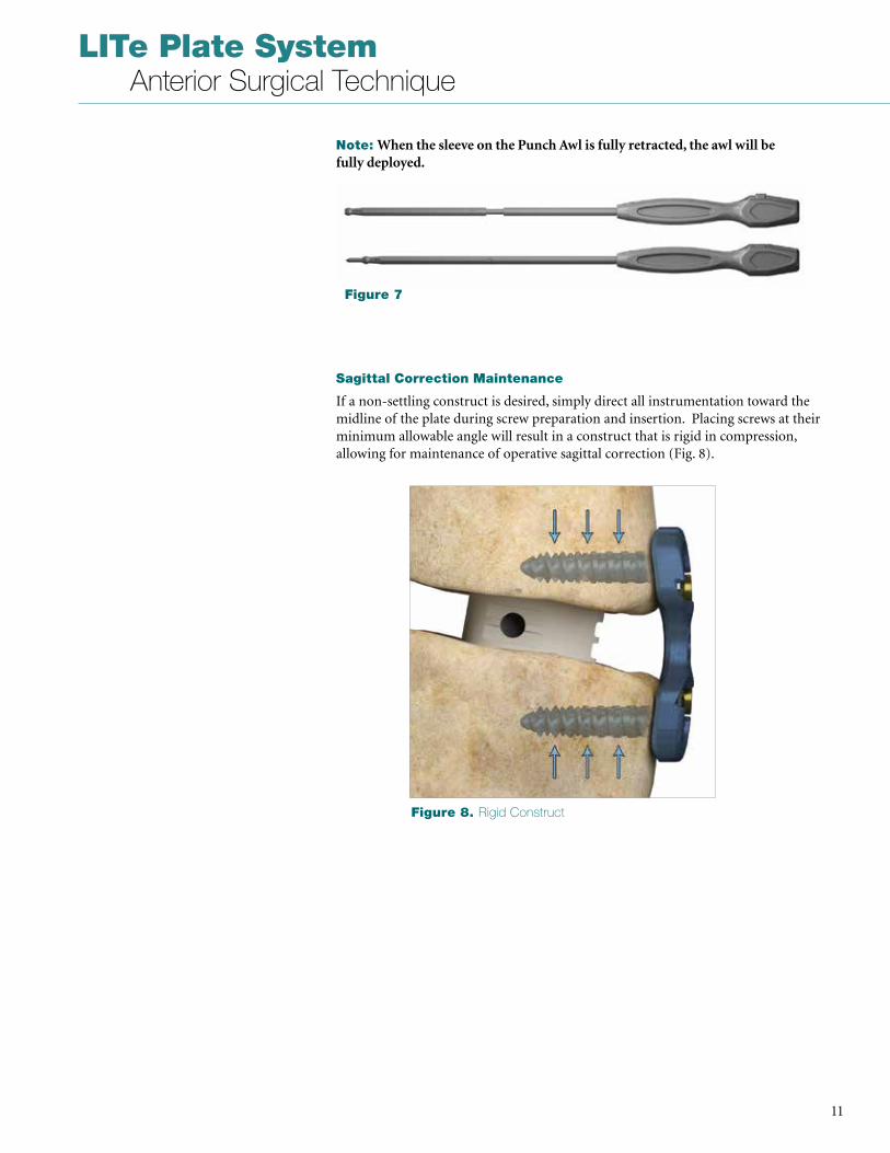
Sagittal Correction Maintenance
If a non-settling construct is desired, simply direct all instrumentation toward the midline of the plate during screw preparation and insertion . Placing screws at their minimum allowable angle will result in a construct that is rigid in compression, allowing for maintenance of operative sagittal correction (Fig . 8) .
Note: When the sleeve on the Punch Awl is fully retracted, the awl will be fully deployed.
Figure 7
Figure 8. Rigid Construct
LITe Plate System Anterior Surgical Technique
12
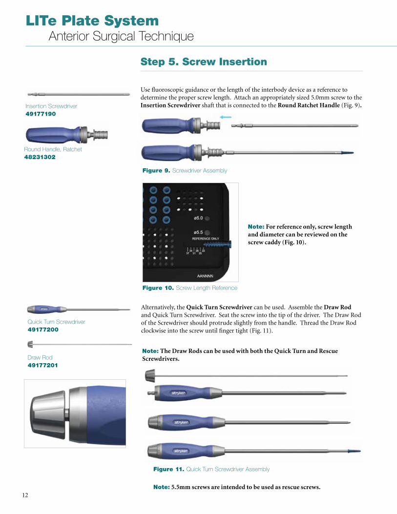
Alternatively, the Quick Turn Screwdriver can be used . Assemble the Draw Rod and Quick Turn Screwdriver . Seat the screw into the tip of the driver . The Draw Rod of the Screwdriver should protrude slightly from the handle . Thread the Draw Rod clockwise into the screw until finger tight (Fig . 11) .
Quick Turn Screwdriver49177200
Draw Rod49177201
Note: The Draw Rods can be used with both the Quick Turn and Rescue Screwdrivers.
Figure 9. Screwdriver Assembly
Figure 10. Screw Length Reference
Figure 11. Quick Turn Screwdriver Assembly
Step 5. Screw Insertion
Use fluoroscopic guidance or the length of the interbody device as a reference to determine the proper screw length . Attach an appropriately sized 5 .0mm screw to the Insertion Screwdriver shaft that is connected to the Round Ratchet Handle (Fig . 9).Insertion Screwdriver
49177190
Round Handle, Ratchet48231302
Note: 5.5mm screws are intended to be used as rescue screws.
Note: For reference only, screw length and diameter can be reviewed on the screw caddy (Fig. 10).
13
LITe Plate System Anterior Surgical Technique
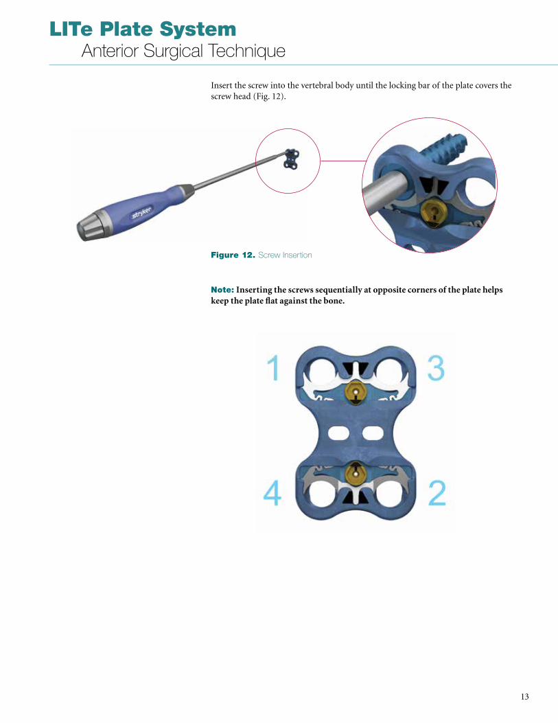
Insert the screw into the vertebral body until the locking bar of the plate covers the screw head (Fig . 12) .
Note: Inserting the screws sequentially at opposite corners of the plate helps keep the plate flat against the bone.
Figure 12. Screw Insertion
LITe Plate System Anterior Surgical Technique
14
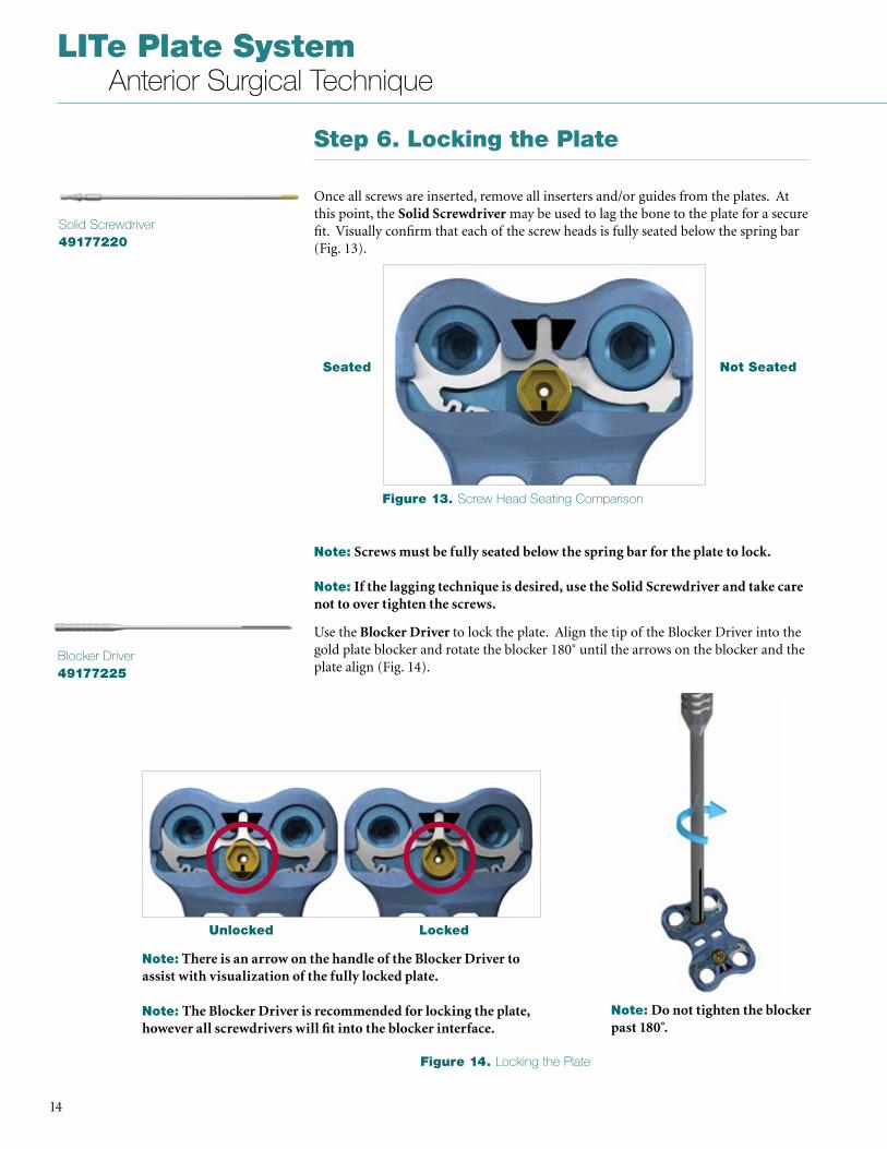
Step 6. Locking the Plate
Once all screws are inserted, remove all inserters and/or guides from the plates . At this point, the Solid Screwdriver may be used to lag the bone to the plate for a secure fit . Visually confirm that each of the screw heads is fully seated below the spring bar (Fig . 13) .
Solid Screwdriver49177220
Use the Blocker Driver to lock the plate . Align the tip of the Blocker Driver into the gold plate blocker and rotate the blocker 180˚ until the arrows on the blocker and the plate align (Fig . 14) .
Blocker Driver49177225
Unlocked Locked
Seated Not Seated
Note: Screws must be fully seated below the spring bar for the plate to lock.
Note: If the lagging technique is desired, use the Solid Screwdriver and take care not to over tighten the screws.
Note: Do not tighten the blocker past 180 .̊
Note: There is an arrow on the handle of the Blocker Driver to assist with visualization of the fully locked plate.
Note: The Blocker Driver is recommended for locking the plate, however all screwdrivers will fit into the blocker interface.
Figure 13. Screw Head Seating Comparison
Figure 14. Locking the Plate
15
LITe Plate System Anterior Surgical Technique
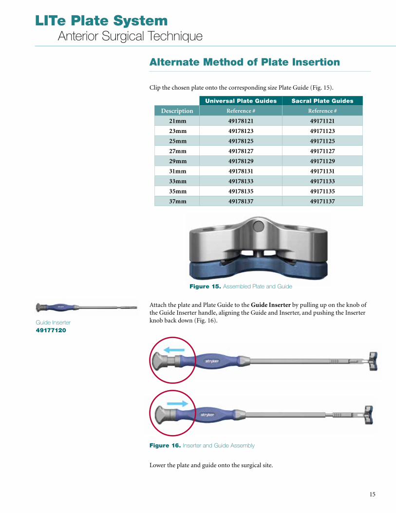
Alternate Method of Plate Insertion
Clip the chosen plate onto the corresponding size Plate Guide (Fig . 15) .
Guide Inserter49177120
Attach the plate and Plate Guide to the Guide Inserter by pulling up on the knob of the Guide Inserter handle, aligning the Guide and Inserter, and pushing the Inserter knob back down (Fig . 16) .
Lower the plate and guide onto the surgical site .
Universal Plate Guides Sacral Plate Guides
Description Reference # Reference #
21mm 49178121 49171121
23mm 49178123 49171123
25mm 49178125 49171125
27mm 49178127 49171127
29mm 49178129 49171129
31mm 49178131 49171131
33mm 49178133 49171133
35mm 49178135 49171135
37mm 49178137 49171137
Figure 15. Assembled Plate and Guide
Figure 16. Inserter and Guide Assembly
LITe Plate System Anterior Surgical Technique
16
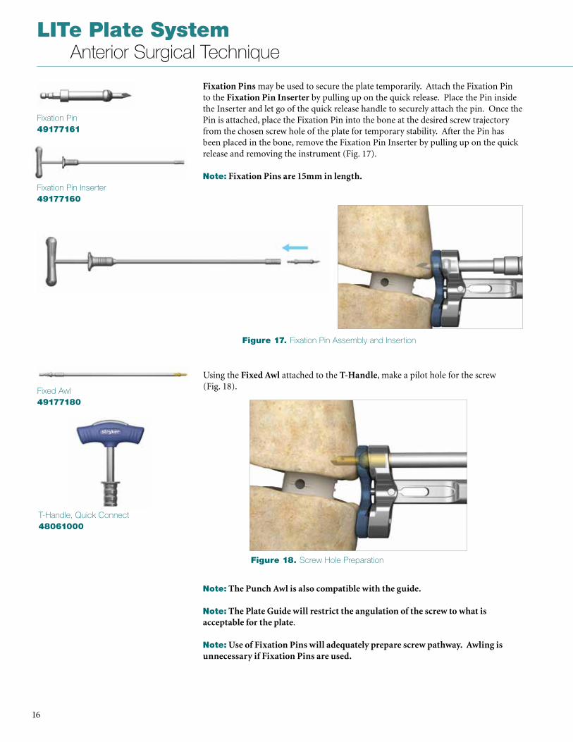
Fixation Pins may be used to secure the plate temporarily . Attach the Fixation Pin to the Fixation Pin Inserter by pulling up on the quick release . Place the Pin inside the Inserter and let go of the quick release handle to securely attach the pin . Once the Pin is attached, place the Fixation Pin into the bone at the desired screw trajectory from the chosen screw hole of the plate for temporary stability . After the Pin has been placed in the bone, remove the Fixation Pin Inserter by pulling up on the quick release and removing the instrument (Fig . 17) .
Note: Fixation Pins are 15mm in length.
Fixation Pin49177161
Fixation Pin Inserter49177160
Using the Fixed Awl attached to the T-Handle, make a pilot hole for the screw (Fig . 18) . Fixed Awl
49177180
Note: The Punch Awl is also compatible with the guide.
Note: The Plate Guide will restrict the angulation of the screw to what is acceptable for the plate .
Note: Use of Fixation Pins will adequately prepare screw pathway. Awling is unnecessary if Fixation Pins are used.
T-Handle, Quick Connect48061000
Figure 17. Fixation Pin Assembly and Insertion
Figure 18. Screw Hole Preparation
17
LITe Plate System Anterior Surgical Technique
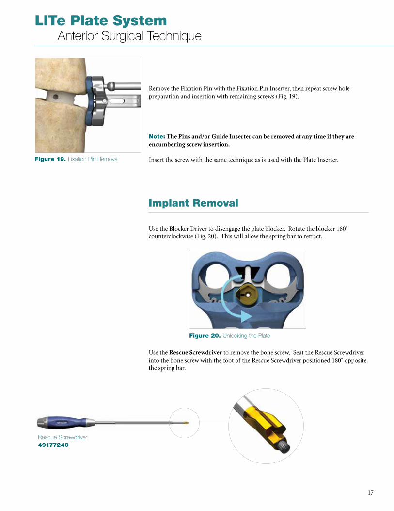
Remove the Fixation Pin with the Fixation Pin Inserter, then repeat screw hole preparation and insertion with remaining screws (Fig . 19) .
Note: The Pins and/or Guide Inserter can be removed at any time if they are encumbering screw insertion.
Insert the screw with the same technique as is used with the Plate Inserter .
Implant Removal
Use the Blocker Driver to disengage the plate blocker . Rotate the blocker 180˚ counterclockwise (Fig . 20) . This will allow the spring bar to retract .
Use the Rescue Screwdriver to remove the bone screw . Seat the Rescue Screwdriver into the bone screw with the foot of the Rescue Screwdriver positioned 180˚ opposite the spring bar .
Figure 19. Fixation Pin Removal
Figure 20. Unlocking the Plate
Rescue Screwdriver49177240
LITe Plate System Anterior Surgical Technique
18
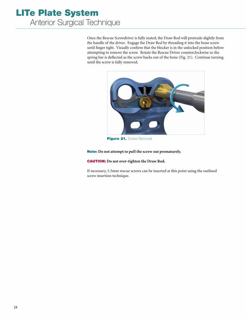
Once the Rescue Screwdriver is fully seated, the Draw Rod will protrude slightly from the handle of the driver . Engage the Draw Rod by threading it into the bone screw until finger tight . Visually confirm that the blocker is in the unlocked position before attempting to remove the screw . Rotate the Rescue Driver counterclockwise so the spring bar is deflected as the screw backs out of the bone (Fig . 21) . Continue turning until the screw is fully removed .
Note: Do not attempt to pull the screw out prematurely.
CAUTION: Do not over-tighten the Draw Rod.
If necessary, 5 .5mm rescue screws can be inserted at this point using the outlined screw insertion technique .
Figure 21. Screw Removal
19
LITe Plate System Anterior Surgical Technique
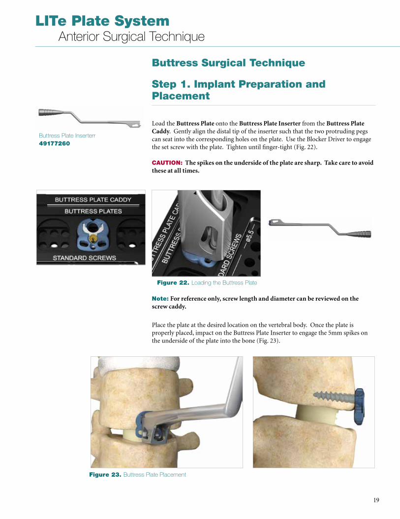
Step 1. Implant Preparation and Placement
Load the Buttress Plate onto the Buttress Plate Inserter from the Buttress Plate Caddy . Gently align the distal tip of the inserter such that the two protruding pegs can seat into the corresponding holes on the plate . Use the Blocker Driver to engage the set screw with the plate . Tighten until finger-tight (Fig . 22) . CAUTION: The spikes on the underside of the plate are sharp. Take care to avoid these at all times.
Buttress Surgical Technique
Buttress Plate Inserterr49177260
Note: For reference only, screw length and diameter can be reviewed on the screw caddy.
Place the plate at the desired location on the vertebral body . Once the plate is properly placed, impact on the Buttress Plate Inserter to engage the 5mm spikes on the underside of the plate into the bone (Fig . 23) .
Figure 22. Loading the Buttress Plate
Figure 23. Buttress Plate Placement
LITe Plate System Anterior Surgical Technique
20
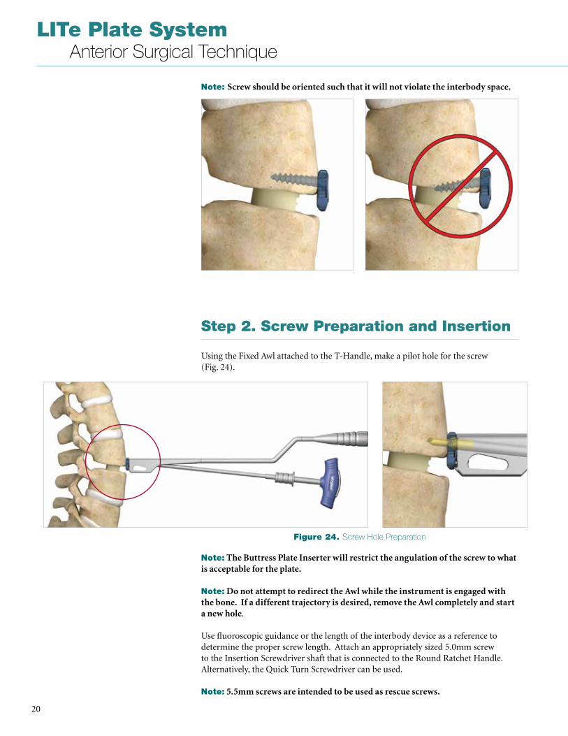
Step 2. Screw Preparation and Insertion
Using the Fixed Awl attached to the T-Handle, make a pilot hole for the screw (Fig . 24) .
Note: Screw should be oriented such that it will not violate the interbody space.
Note: The Buttress Plate Inserter will restrict the angulation of the screw to what is acceptable for the plate.
Note: Do not attempt to redirect the Awl while the instrument is engaged with the bone. If a different trajectory is desired, remove the Awl completely and start a new hole .
Use fluoroscopic guidance or the length of the interbody device as a reference to determine the proper screw length . Attach an appropriately sized 5 .0mm screw to the Insertion Screwdriver shaft that is connected to the Round Ratchet Handle . Alternatively, the Quick Turn Screwdriver can be used .
Note: 5.5mm screws are intended to be used as rescue screws.
Figure 24. Screw Hole Preparation
21
LITe Plate System Anterior Surgical Technique
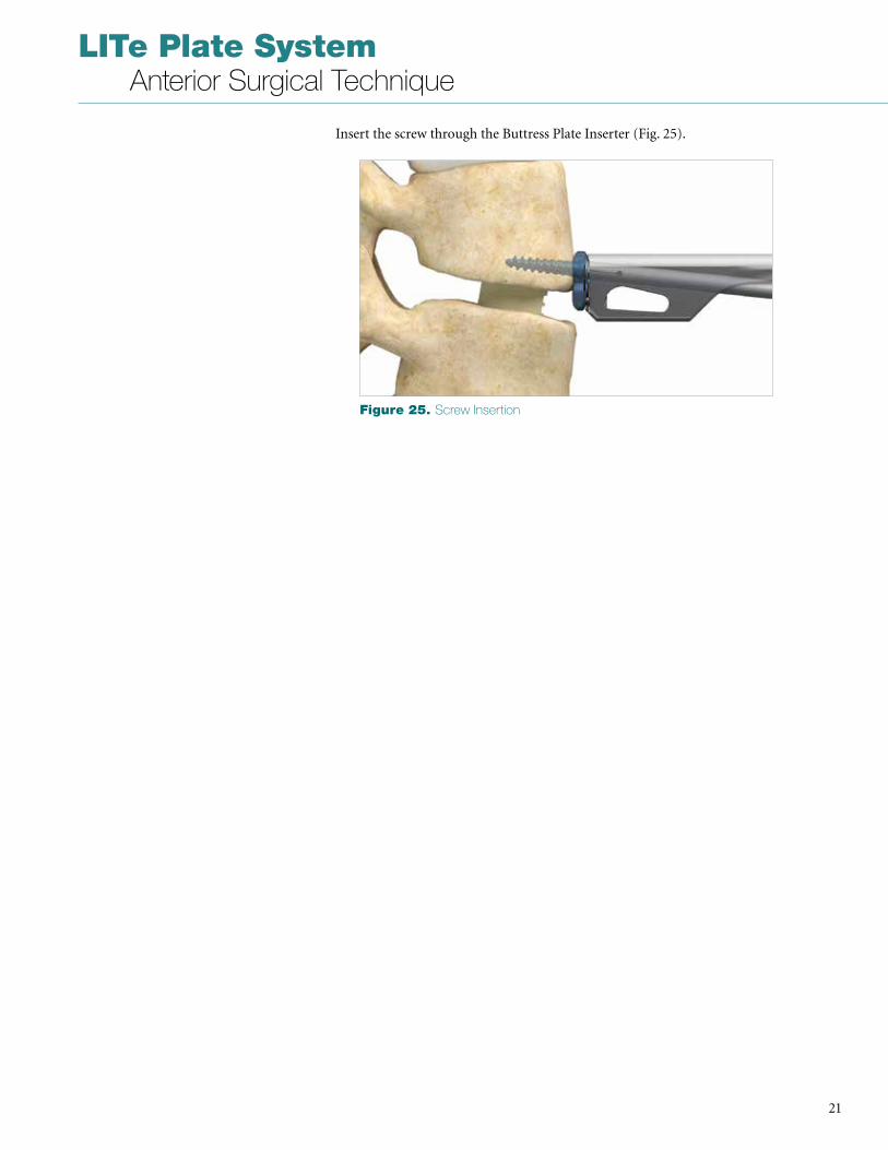
Insert the screw through the Buttress Plate Inserter (Fig . 25) .
Figure 25. Screw Insertion
LITe Plate System Anterior Surgical Technique
22
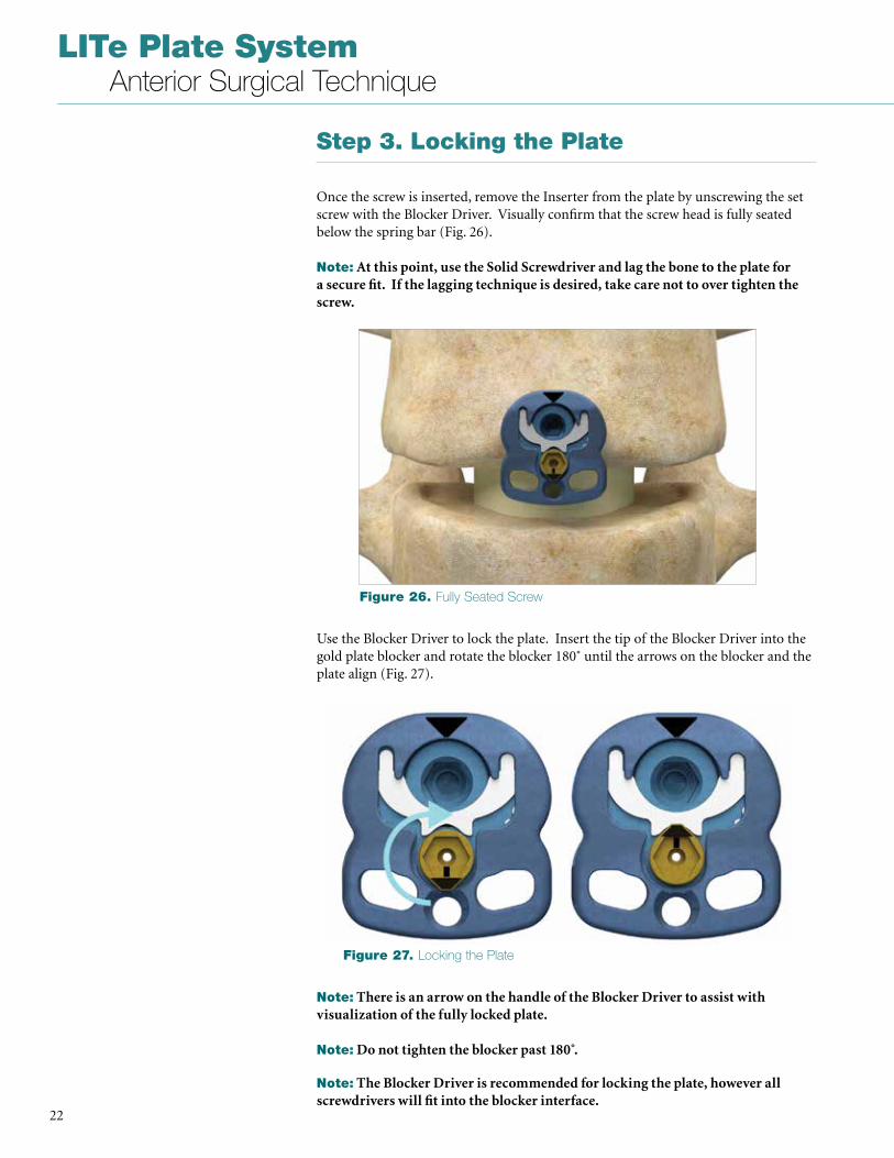
Step 3. Locking the Plate
Once the screw is inserted, remove the Inserter from the plate by unscrewing the set screw with the Blocker Driver . Visually confirm that the screw head is fully seated below the spring bar (Fig . 26) .
Note: At this point, use the Solid Screwdriver and lag the bone to the plate for a secure fit. If the lagging technique is desired, take care not to over tighten the screw.
Use the Blocker Driver to lock the plate . Insert the tip of the Blocker Driver into the gold plate blocker and rotate the blocker 180˚ until the arrows on the blocker and the plate align (Fig . 27) .
Note: There is an arrow on the handle of the Blocker Driver to assist with visualization of the fully locked plate.
Note: Do not tighten the blocker past 180 .̊
Note: The Blocker Driver is recommended for locking the plate, however all screwdrivers will fit into the blocker interface.
Figure 26. Fully Seated Screw
Figure 27. Locking the Plate
23
LITe Plate System Anterior Surgical Technique
Implant Removal
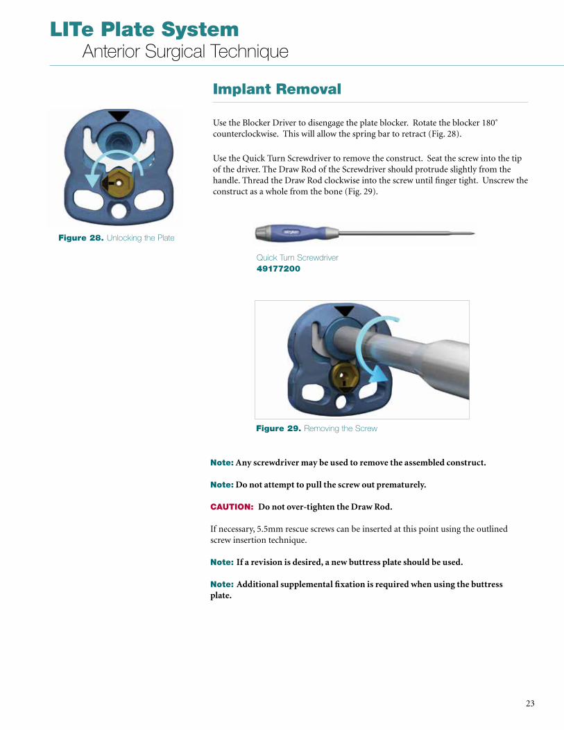
Use the Blocker Driver to disengage the plate blocker . Rotate the blocker 180˚ counterclockwise . This will allow the spring bar to retract (Fig . 28) .
Use the Quick Turn Screwdriver to remove the construct . Seat the screw into the tip of the driver . The Draw Rod of the Screwdriver should protrude slightly from the handle . Thread the Draw Rod clockwise into the screw until finger tight . Unscrew the construct as a whole from the bone (Fig . 29) .
Note: Any screwdriver may be used to remove the assembled construct.
Note: Do not attempt to pull the screw out prematurely.
CAUTION: Do not over-tighten the Draw Rod.
If necessary, 5 .5mm rescue screws can be inserted at this point using the outlined screw insertion technique .
Note: If a revision is desired, a new buttress plate should be used.
Note: Additional supplemental fixation is required when using the buttress plate.
Figure 28. Unlocking the Plate
Figure 29. Removing the Screw
Quick Turn Screwdriver49177200
LITe Plate System Anterior Surgical Technique
24
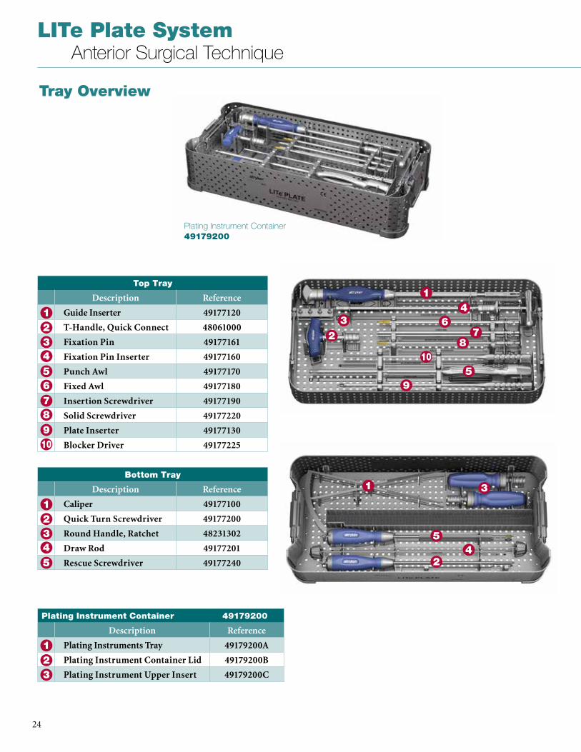
Tray Overview
Plating Instrument Container 49179200
Top Tray
Description Reference
Guide Inserter 49177120
T-Handle, Quick Connect 48061000
Fixation Pin 49177161
Fixation Pin Inserter 49177160
Punch Awl 49177170
Fixed Awl 49177180
Insertion Screwdriver 49177190
Solid Screwdriver 49177220
Plate Inserter 49177130
Blocker Driver 49177225
5
1234
6
9
78
10
6
1
2
4
5
3
9
78
10
Bottom Tray
Description Reference
Caliper 49177100
Quick Turn Screwdriver 49177200
Round Handle, Ratchet 48231302
Draw Rod 49177201
Rescue Screwdriver 491772405
1234
1
24
5
3
Plating Instrument Container 49179200
Description Reference
Plating Instruments Tray 49179200A
Plating Instrument Container Lid 49179200B
Plating Instrument Upper Insert 49179200C
123
25
LITe Plate System Anterior Surgical Technique
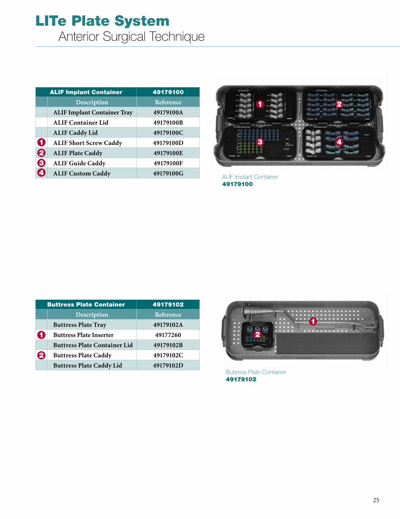
ALIF Implant Container 49179100
ALIF Implant Container 49179100
Description Reference
ALIF Implant Container Tray 49179100A
ALIF Container Lid 49179100B
ALIF Caddy Lid 49179100C
ALIF Short Screw Caddy 49179100D
ALIF Plate Caddy 49179100E
ALIF Guide Caddy 49179100F
ALIF Custom Caddy 49179100G
1234
1 2
43
1
2
Buttress Plate Container 49179102
Description Reference
Buttress Plate Tray 49179102A
Buttress Plate Inserter 49177260
Buttress Plate Container Lid 49179102B
Buttress Plate Caddy 49179102C
Buttress Plate Caddy Lid 49179102D
1
2
Buttress Plate Container 49179102
LITe Plate System Anterior Surgical Technique
26
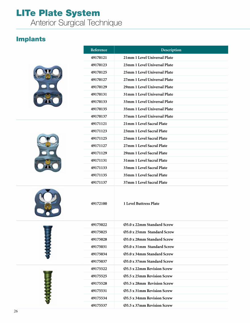
Implants
Reference Description
49170121 21mm 1 Level Universal Plate
49170123 23mm 1 Level Universal Plate
49170125 25mm 1 Level Universal Plate
49170127 27mm 1 Level Universal Plate
49170129 29mm 1 Level Universal Plate
49170131 31mm 1 Level Universal Plate
49170133 33mm 1 Level Universal Plate
49170135 35mm 1 Level Universal Plate
49170137 37mm 1 Level Universal Plate
49171121 21mm 1 Level Sacral Plate
49171123 23mm 1 Level Sacral Plate
49171125 25mm 1 Level Sacral Plate
49171127 27mm 1 Level Sacral Plate
49171129 29mm 1 Level Sacral Plate
49171131 31mm 1 Level Sacral Plate
49171133 33mm 1 Level Sacral Plate
49171135 35mm 1 Level Sacral Plate
49171137 37mm 1 Level Sacral Plate
49172100 1 Level Buttress Plate
49175022 Ø5.0 x 22mm Standard Screw
49175025 Ø5.0 x 25mm Standard Screw
49175028 Ø5.0 x 28mm Standard Screw
49175031 Ø5.0 x 31mm Standard Screw
49175034 Ø5.0 x 34mm Standard Screw
49175037 Ø5.0 x 37mm Standard Screw
49175522 Ø5.5 x 22mm Revision Screw
49175525 Ø5.5 x 25mm Revision Screw
49175528 Ø5.5 x 28mm Revision Screw
49175531 Ø5.5 x 31mm Revision Screw
49175534 Ø5.5 x 34mm Revision Screw
49175537 Ø5.5 x 37mm Revision Screw
27
LITe Plate System Anterior Surgical Technique
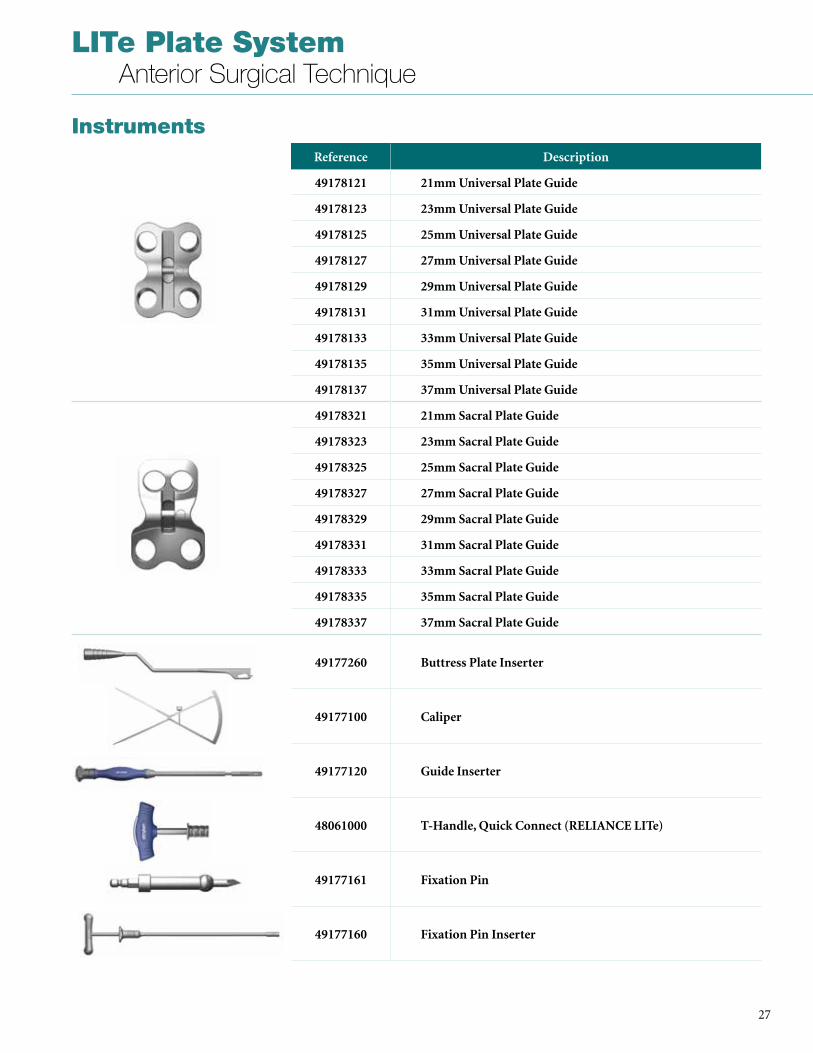
InstrumentsReference Description
49178121 21mm Universal Plate Guide
49178123 23mm Universal Plate Guide
49178125 25mm Universal Plate Guide
49178127 27mm Universal Plate Guide
49178129 29mm Universal Plate Guide
49178131 31mm Universal Plate Guide
49178133 33mm Universal Plate Guide
49178135 35mm Universal Plate Guide
49178137 37mm Universal Plate Guide
49178321 21mm Sacral Plate Guide
49178323 23mm Sacral Plate Guide
49178325 25mm Sacral Plate Guide
49178327 27mm Sacral Plate Guide
49178329 29mm Sacral Plate Guide
49178331 31mm Sacral Plate Guide
49178333 33mm Sacral Plate Guide
49178335 35mm Sacral Plate Guide
49178337 37mm Sacral Plate Guide
49177260 Buttress Plate Inserter
49177100 Caliper
49177120 Guide Inserter
48061000 T-Handle, Quick Connect (RELIANCE LITe)
49177161 Fixation Pin
49177160 Fixation Pin Inserter
LITe Plate System Anterior Surgical Technique
28
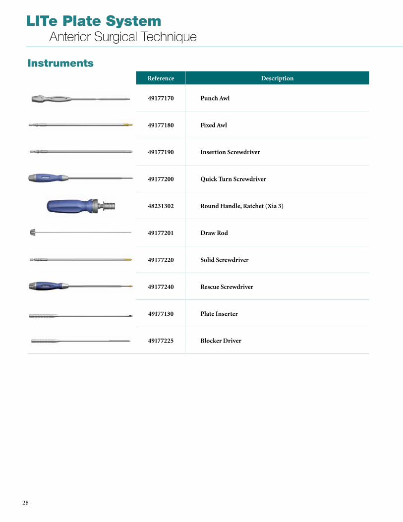
InstrumentsReference Description
49177170 Punch Awl
49177180 Fixed Awl
49177190 Insertion Screwdriver
49177200 Quick Turn Screwdriver
48231302 Round Handle, Ratchet (Xia 3)
49177201 Draw Rod
49177220 Solid Screwdriver
49177240 Rescue Screwdriver
49177130 Plate Inserter
49177225 Blocker Driver
29
LITe Plate System Anterior Surgical Technique
IMPORTANT PRODUCT INFORMATION
DESCRIPTIONThe Stryker Spine LITe Plate System is comprised of devices intended for the fixation of the non-cervical spine . It includes a variety of non-sterile plates and bone screws manufactured from Titanium Alloy .
MATERIALSTitanium Alloy: Ti6Al4V according to ISO 5832-3 and ASTM F-136: screws and plates .
INDICATIONS FOR LITE PLATE SYSTEM UNIVERSAL, SACRAL, 2 SCREW AND 4 SCREW PLATESThe LITe Plate System Universal, Sacral, 2 Screw and 4 Screw Plates are indicated for use via a lateral or anterolateral surgical approach above the bifurcation of the great vessels in the treatment of the thoracic and thoracolumbar (T1-L5) spine or via an anterior approach below the bifurcation of the great vessels in the treatment of lumbar and lumbosacral (L1-S1) spine . The system is intended to provide additional support during fusion in skeletally mature patients in the treatment of the following acute and chronic instabilities or deformities:• Degenerative Disc Disease (defined as back
pain of discogenic origin with degeneration of the disc confirmed by patient history and radiographic studies);
• Pseudoarthrosis;• Spondylolysis;• Spondylolisthesis;• Spinal stenosis;• Tumors;• Trauma (i .e . Fractures or Dislocation)• Deformities (i .e . Scoliosis, Kyphosis or
Lordosis)• Failed Previous Fusion
INDICATIONS FOR LITE PLATE SYSTEM BUTTRESS PLATEThe LITe Plate System Buttress Plate is intended to stabilize the allograft or autograft at one level (T1-S1) as an aid to spinal fusion and to provide temporary stabilization and augment development of a solid spinal fusion . It may be used alone or with other anterior, anterolateral, or posterior spinal systems made of compatible materials . This device is not intended for load bearing applications .
CONTRAINDICATIONSContraindications may be relative or absolute . The choice of a particular device must be carefully weighed against the patient’s overall evaluation . Circumstances listed below may reduce the chances of a successful outcome:• Any abnormality present which affects the
normal process of bone remodeling including, but not limited to, severe
osteoporosis involving the spine, bone absorption, osteopenia, primary or metastatic tumors involving the spine, active infection at the site or certain metabolic disorders affecting osteogenesis .
• Insufficient quality or quantity of bone which would inhibit rigid device fixation .
• Previous history of infection• Excessive local inflammation • Open wounds• Any neuromuscular deficit which places an
unusually heavy load on the device during the healing period .
• Obesity . An overweight or obese patient can produce loads on the spinal system which can lead to failure of the fixation of the device or to failure of the device itself .
• Patients having inadequate tissue coverage of the operative site .
• Pregnancy .• A condition of senility, mental illness, or
substance abuse . These conditions, among others, may cause the patient to ignore certain necessary limitations and precautions in the use of the implant, leading to failure or other complications .
• Foreign body sensitivity . Where material sensitivity is suspected, appropriate tests must be made prior to material selection or implantation .
• Other medical or surgical condition which would preclude the potential benefit of spinal implant surgery, such as the presence of tumors, congenital abnormalities, elevation of sedimentation rate unexplained by other diseases, elevation of white blood cell count (WBC), or marked left shift in the WBC differential count .
These contraindications can be relative or absolute and must be taken into account by the physician when making his decision . The above list is not exhaustive . Surgeons must discuss the relative contraindications with the patients .
CAUTION (U.S.A) Federal law restricts this device to sale by or on the order of a licensed physician
WARNINGS (U.S.A.) These devices are not approved for screw attachment to the posterior elements (pedicles) of the cervical, thoracic, or lumbar spine .
The safety and effectiveness of anterior or lateral plating spinal systems have been established only for spinal conditions with significant mechanical instability or deformity requiring fusion with instrumentation . These conditions are significant mechanical instability or deformity of the thoracic, lumbar, and sacral spine secondary to spondylolisthesis,
fracture, dislocation, scoliosis, kyphosis, spinal tumor, and failed previous fusion (pseudoarthrosis) . The safety and effectiveness of these devices for any other conditions are unknown .
The LITe Plate System has not been tested for heating or migration in the MR environment .
PRECAUTIONS (U.S.A.)The implanation of anterior or lateral plate spinal systems must be performed only by experienced spinal surgeons with specific training in the use of this spinal plate system because this is a technically demanding procedure presenting a risk of serious injury to the patient .
Based on the fatigue testing results, the physician/surgeon must consider the levels of implantation, patient weight, patient activity level, other patient conditions, etc . which may impact on the performance of the system .
GENERAL CONDITIONS OF USEThe implantation of spinal systems must be performed only by experienced spinal surgeons having undergone the necessary specific training in the use of such systems because this is a technically demanding procedure presenting a risk of serious injury to the patient .
The information contained in the Package Insert is necessary but not sufficient for the use of this device . This information is in no sense intended as a substitute for the professional judgment, skill and experience of the surgeon in careful patient selection, preoperative planning and device selection, knowledge of the anatomy and biomechanics of the spine, understanding of the materials and the mechanical characteristics of the implants used, training and skill in spinal surgery and the use of associated instruments for implantation, securing the patient’s cooperation in following an appropriately defined post-operative management program and conducting scheduled post-operative follow-up examinations .
INFORMATION FOR PATIENTSThe surgeon must discuss all physical and psychological limitations inherent to the use of the device with the patient . This includes the rehabilitation regimen, physical therapy, and wearing an appropriate orthosis as prescribed by the physician . Particular discussion should be directed to the issues of premature weightbearing, activity levels, and the necessity for periodic medical follow-up .
LITe Plate System Anterior Surgical Technique
30
The surgeon must warn patients of the surgical risks and make them aware of possible adverse effects . The patient must be warned that the device cannot and does not replicate the flexibility, strength, reliability or durability of normal healthy bone, that the implant can break or become damaged as a result of strenuous activity or trauma, and that the device may need to be replaced in the future . If the patient is involved in an occupation or activity which applies inordinate stress upon the implant (e .g ., substantial walking, running, lifting, or muscle strain)the surgeon must warn the patient that resultant forces can cause failure of the device . Patients who smoke have been shown to have an increased incidence of non-unions . Such patients must be advised of this fact and warned of the potential consequences . For diseased patients with degenerative disease, the progression of degenerative disease may be so advanced at the time of implantation that it may substantially decrease the expected useful life of the appliance . In such cases, orthopaedic devices may be considered only as a delaying technique or to provide temporary relief .
INFECTIONTransient bacteremia can occur in daily life . Dental manipulation, endoscopic examination and other minor surgical procedures have been associated with transient bacteremia . To help prevent infection at the implant site, it may be advisable to use antibiotic prophylaxis before and after such procedures .
INSTRUMENTSSurgical instruments are provided by Stryker Spine and must be used to assure accurate implantation of the device . While rare, intraoperative fracture or breakage of instruments can occur . Instruments which have experienced extensive use or extensive force are more susceptible to fracture depending on the operative precaution, number of procedures, disposal attention . Instruments must be examined for wear or damage prior to surgery and after sterilization .
REUSENever reuse or re-implant spinal surgical implants . These could become contaminated resulting in infection . In addition, even though the device appears undamaged, it may have small defects which could compromise structural integrity reducing its service life and/or leading to patient injury .
HANDLINGCorrect handling of the implant is extremely important . The operating surgeon should avoid notching or scratching the device .
ALLERGY AND HYPERSENSITIVITY TO FOREIGN BODIES When hypersensitivity is suspected or proven, it is recommended that the tolerance of the skin to the materials that make up the implants be checked before they are implanted .
PRE-OPERATIVE PRECAUTIONSAnyone using Stryker Spine products can obtain a Surgical Technique brochure by requesting one from a distributor or from Stryker Spine directly . Those using brochures published more than two years before the surgical intervention are advised to get an updated version .
Stryker Spine devices can only be used by doctors who are fully familiar with the surgical technique required and who have been trained to this end . The doctor operating must take care not to use the instruments to exert inappropriate stress on the spine or the implants and must scrupulously comply with any operating procedure described in the surgical technique provided by Stryker Spine . For example, the forces exerted when repositioning an instrument in-situ must not be excessive as this is likely to causes injury to the patient .
To reduce the risks of breakage, care must be taken not to distort the implants or nick, hit or score them with the instruments unless otherwise specified by the applicable Stryker Spine Surgical Technique .
Extreme care must be taken when the instruments are used near vital organs, nerves or vessels .
Unless otherwise specified on the label, the instruments can be reused after decontamination, cleaning and sterilization .
IMPLANT SELECTION AND USEThe choice of proper shape, size and design of the implant for each patient is crucial to the success of the surgery . The surgeon is responsible for this choice which depends on each patient .
Patients who are overweight may be responsible for additional stresses and strains on the device which can speed up metal fatigue and/or lead to deformation or failure of the implants .
The size and shape of the bone structures determine the size, shape and type of the implants . Once implanted, the implants are subjected to stresses and strains . These repeated stresses on the implants should be taken into consideration by the surgeon at the time of the choice of the implant, during implantation as well as in the post-operative follow-up period . Indeed, the stresses and strains on the implants may cause metal fatigue or fracture or deformation of the implants, before the bone graft has become completely consolidated . This may result in further side effects or necessitate the early removal of the osteosynthesis device .
Improper selection, placement, positioning and fixation of these devices may result in unusual stress conditions reducing the service life of the implant . Contouring or bending of rods or plates is recommended only if necessary according to the surgical technique of each system . Rods or plates should only be contoured with the proper contouring instruments . Incorrectly contoured rods/plates, or rods/plates which have been repeatedly or excessively contoured must not be implanted . The surgeon is to be thoroughly familiar with the surgical procedure, instruments and implant characteristics prior to performing surgery . Refer to the Stryker Spine surgical protocols for additional procedural information . Periodic follow-up is recommended to monitor the position and state of the implants, as well as the condition of the adjoining bone .
METAL COMPONENTSSome of the alloys utilized to produce orthopaedic implants contain metallic elements that may be carcinogenic in tissue cultures or intact organisms under unique circumstances . Questions have been raised in the scientific literature as to whether or not these alloys themselves may be carcinogenic in implant recipients . Studies conducted to evaluate this issue have not identified conclusive evidence of such phenomena .
SYSTEM COMPATIBILITYWhile some degree of corrosion occurs on all implanted metal and alloys, contact of dissimilar metals may accelerate this corrosion process . The presence of corrosion may accelerate fatigue fracture of implants and the amount of metal compounds released into the body system will also increase . Internal fixation devices, such as plates, screws, etc ., which come into contact with other metal objects, must be made from like or compatible metals . Because different manufacturers employ
31
LITe Plate System Anterior Surgical Technique
different materials, varying tolerances and manufacturing specifications, and differing design parameters, components of the system must not be used in conjunction with components from any other manufacturer’s spinal system . Any such use will negate the responsibility of Stryker Spine for the performance of the resulting mixed component implant .
INTRA-OPERATIVE PRECAUTIONS• The insertion of the implants must be
carried out using instruments designed and provided for this purpose and in accordance with the specific implantation instructions for each implant . Those detailed instructions are provided in the surgical technique brochure supplied by Stryker Spine .
• Discard all damaged or mishandled implants .
• Never reuse an implant, even though it may appear undamaged .
POSTOPERATIVE CAREPrior to adequate maturation of the fusion mass, implanted spinal instrumentation may need additional help to accommodate full load bearing . External support may be recommended by the physician from two to four months postoperatively or until x-rays or other procedures confirm adequate maturation of the fusion mass; external immobilization by bracing or casting may be employed . Surgeons must instruct patients regarding appropriate and restricted activities during consolidation and maturation for the fusion mass in order to prevent placing excessive stress on the implants which may lead to fixation or implant failure and accompanying clinical problems . Surgeons must instruct patients to report any unusual changes of the operative site to his/her physician . The physician should closely monitor the patient if a change at the site has been detected .
ADVERSE EFFECTSWhile the expected life of spinal implant components is difficult to estimate, it is finite . These components are made of foreign materials which are placed within the body designed for the potential fusion of the spine and reduction of pain . However, due to the many biological, mechanical and physicochemical factors which affect these devices but cannot be evaluated in vivo, the components cannot be expected to indefinitely withstand the activity level and
loads of normal healthy bone .
Adverse effects include but are not limited to:• Bending, disassembly or fracture of any or
all implant components .• Fatigue fracture of spinal fixation devices,
including screws and rods, has occurred .• Pain, discomfort, or abnormal sensations
due to the presence of the device .• Pressure on skin from components where
inadequate tissue coverage exists over the implant, with the potential extrusion through the skin .
• Dural leak requiring surgical repair .• Cessation of growth of the fused portion of
the spine .• Loss of proper spinal curvature, correction,
height and/or reduction .• Delayed Union or Nonunion: Internal
fixation appliances are load sharing devices which are designed to obtain alignment until normal healing occurs . In the event that healing is delayed, does not occur, or failure to immobilize the delayed/nonunion results, the implant will be subject to excessive and repeated stresses which can eventually cause loosening, bending or fatigue fracture . The degree or success of union, loads produced by weight bearing, and activity levels will, among other conditions, dictate the longevity of the implant . If a nonunion develops or if the implants loosen, bend or break, the device(s) must be revised or removed immediately before serious injury occurs .
• Loosening of spinal fixation implants can occur . Early mechanical loosening may result from inadequate initial fixation, latent infection, premature loading of the prosthesis or trauma . Late loosening may result from trauma, infection, biological complications or mechanical problems, with the subsequent possibility of bone erosion, migration and/or pain .
• Peripheral neuropathies, nerve damage, heterotopic bone formation and neurovascular compromise, including paralysis, loss of bowel or bladder function, or foot-drop may occur .
• Serious complications may be associated with any spinal surgery . These complications include, but are not limited to: genitourinary disorders; gastrointestinal disorders; vascular disorders, including thrombus; bronchopulmonary disorders, including emboli; bursitis, hemorrhage, myocardial infarction, infection, paralysis or death .
• Neurological, vascular, or soft tissue damage due directly to the unstable nature
of the fracture, or to surgical trauma . • Inappropriate or improper surgical
placement of this device may cause distraction or stress shielding of the graft or fusion mass . This may contribute to failure of an adequate fusion mass to form .
• Decrease in bone density due to stress shielding .
• Intraoperative fissure, fracture, or perforation of the spine can occur due to implantation of the components . Postoperative fracture of bone graft, pedicle, and/or sacrum above and/or below the level of surgery can occur due to trauma, the presence of defects, or poor bone stock .
Adverse effects may necessitate reoperation or revision . The surgeon must warn the patient of these adverse effects as deemed necessary .
REMOVAL OF IMPLANTSThese implants are temporary internal fixation devices designed to stabilize the operative site during the normal healing process . After healing occurs, these devices serve no functional purpose and can be removed . Removal may also be recommended in other cases, such as:• Corrosion with a painful reaction• Migration of the implant, with subsequent
pain and/or neurological, articular or soft tissue lesions
• Pain or abnormal sensations due to the presence of the implants
• Infection or inflammatory reactions• Reduction in bone density due to the
different distribution of mechanical and physiological stresses and strains
• Failure or mobilization of the implant
Standard ancillaries provided by Stryker Spine can be used to remove the implants . Any decision by a physician to remove the internal fixation device must take into consideration such factors as the risk to the patient of the additional surgical procedure as well as the difficulty of removal . Removal of an unloosened spinal screw may require the use of special instruments to disrupt the interface at the implant surface . This technique may require practice in the laboratory before being attempted clinically . Implant removal should be followed by adequate postoperative management to avoid fracture or re-fracture . Removal of the implant after fracture healing is recommended . Metallic implants can loosen, bend, fracture, corrode, migrate, cause pain or stress shield bone .
A surgeon must always rely on his or her own professional clinical judgment when deciding whether to use a particular product when treating a particular patient . Stryker does not dispense medical advice and recommends that surgeons be trained in the use of any particular product before using it in surgery .
The information presented is intended to demonstrate the breadth of Stryker product offerings . A surgeon must always refer to the package insert, product label and/or instructions for use before using any Stryker product . Products may not be available in all markets because product availability is subject to the regulatory and/or medical practices in individual markets . Please contact your Stryker representative if you have questions about the availability of Stryker products in your area . Stryker Corporation or its divisions or other corporate affiliated entities own, use or have applied for the following trademarks or service marks: Aero, AVS, LITe, Reliance, Stryker, Xia . All other trademarks are trademarks of their respective owners or holders .
TLLPS-ST-1_Rev-1SC/GS 12/15
Copyright © 2015 StrykerPrinted in USA
Stryker Spine2 Pearl CourtAllendale, NJ 07401-1677 USAt: 201-760-8000www.stryker.com