Embed Size (px)
Citation preview

LISY1_HWv5.1_Board_Assembly_v1.0.docx Page 1
LISY1
LInux for System1
Hardware Version 5.1
Board Assembly
24.09.2019 Version 1.0
LISY1_HWv5.1_Board_Assembly_v1.0.docx Page 2
table of contents Important remark .................................................................................................................................... 3
1. Bill of material ..................................................................................................................................... 4
1.1. Base function ................................................................................................................................ 4
1.2. Wireless LAN option ..................................................................................................................... 5
1.3. Sound Option ................................................................................................................................ 5
2. Step by Step ......................................................................................................................................... 6
2.1. Step1: X1, diodes, resistors, IC-Sockets and Kerkos ..................................................................... 6
2.2. Step 2. LEDs and resistor arrays ................................................................................................... 7
2.3. Step 3, Elko C1 & Switches S1, S2 und S3/S4 ............................................................................... 8
2.4. Step 4, Male Header K1 & K2 und socket for Raspberry PI .......................................................... 8
2.5. Step 5, Placement of all IC and the Raspberry PI ....................................................................... 10
2.6. Use of alternate contacts ........................................................................................................... 11
LISY1_HWv5.1_Board_Assembly_v1.0.docx Page 3
Important remark
By using LISY1 it is possible to damage your pinball machine. As this is a private
project with NO commercial interest the author accepts no liability for any
damage that may arise by using LISY1!
LISY1_HWv5.1_Board_Assembly_v1.0.docx Page 4
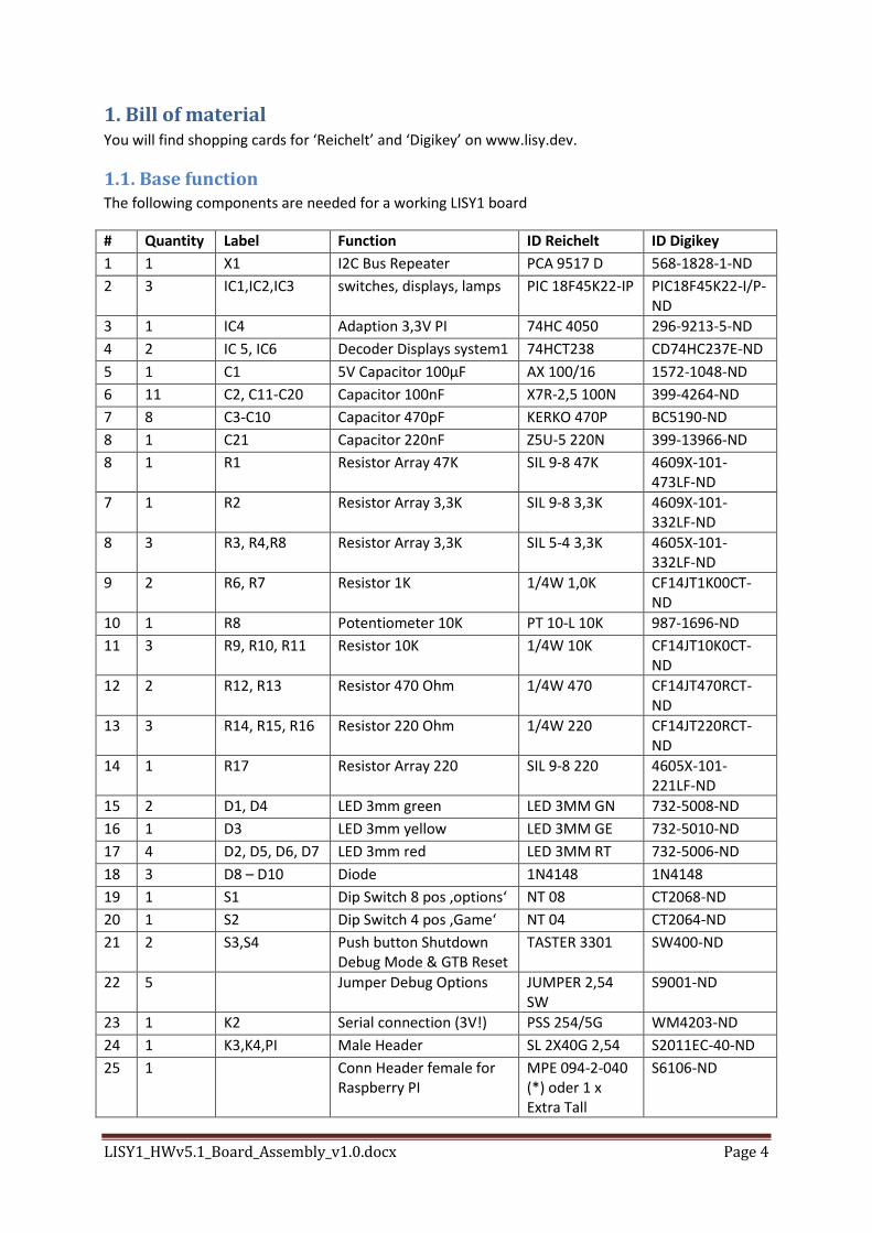
1. Bill of material You will find shopping cards for ‘Reichelt’ and ‘Digikey’ on www.lisy.dev.
1.1. Base function The following components are needed for a working LISY1 board
# Quantity Label Function ID Reichelt ID Digikey
1 1 X1 I2C Bus Repeater PCA 9517 D 568-1828-1-ND
2 3 IC1,IC2,IC3 switches, displays, lamps PIC 18F45K22-IP PIC18F45K22-I/P-ND
3 1 IC4 Adaption 3,3V PI 74HC 4050 296-9213-5-ND
4 2 IC 5, IC6 Decoder Displays system1 74HCT238 CD74HC237E-ND
5 1 C1 5V Capacitor 100µF AX 100/16 1572-1048-ND
6 11 C2, C11-C20 Capacitor 100nF X7R-2,5 100N 399-4264-ND
7 8 C3-C10 Capacitor 470pF KERKO 470P BC5190-ND
8 1 C21 Capacitor 220nF Z5U-5 220N 399-13966-ND
8 1 R1 Resistor Array 47K SIL 9-8 47K 4609X-101-473LF-ND
7 1 R2 Resistor Array 3,3K SIL 9-8 3,3K 4609X-101-332LF-ND
8 3 R3, R4,R8 Resistor Array 3,3K SIL 5-4 3,3K 4605X-101-332LF-ND
9 2 R6, R7 Resistor 1K 1/4W 1,0K CF14JT1K00CT-ND
10 1 R8 Potentiometer 10K PT 10-L 10K 987-1696-ND
11 3 R9, R10, R11 Resistor 10K 1/4W 10K CF14JT10K0CT-ND
12 2 R12, R13 Resistor 470 Ohm 1/4W 470 CF14JT470RCT-ND
13 3 R14, R15, R16 Resistor 220 Ohm 1/4W 220 CF14JT220RCT-ND
14 1 R17 Resistor Array 220 SIL 9-8 220 4605X-101-221LF-ND
15 2 D1, D4 LED 3mm green LED 3MM GN 732-5008-ND
16 1 D3 LED 3mm yellow LED 3MM GE 732-5010-ND
17 4 D2, D5, D6, D7 LED 3mm red LED 3MM RT 732-5006-ND
18 3 D8 – D10 Diode 1N4148 1N4148
19 1 S1 Dip Switch 8 pos ‚options‘ NT 08 CT2068-ND
20 1 S2 Dip Switch 4 pos ‚Game‘ NT 04 CT2064-ND
21 2 S3,S4 Push button Shutdown Debug Mode & GTB Reset
TASTER 3301 SW400-ND
22 5 Jumper Debug Options JUMPER 2,54 SW
S9001-ND
23 1 K2 Serial connection (3V!) PSS 254/5G WM4203-ND
24 1 K3,K4,PI Male Header SL 2X40G 2,54 S2011EC-40-ND
25 1 Conn Header female for Raspberry PI
MPE 094-2-040 (*) oder 1 x Extra Tall
S6106-ND
LISY1_HWv5.1_Board_Assembly_v1.0.docx Page 5
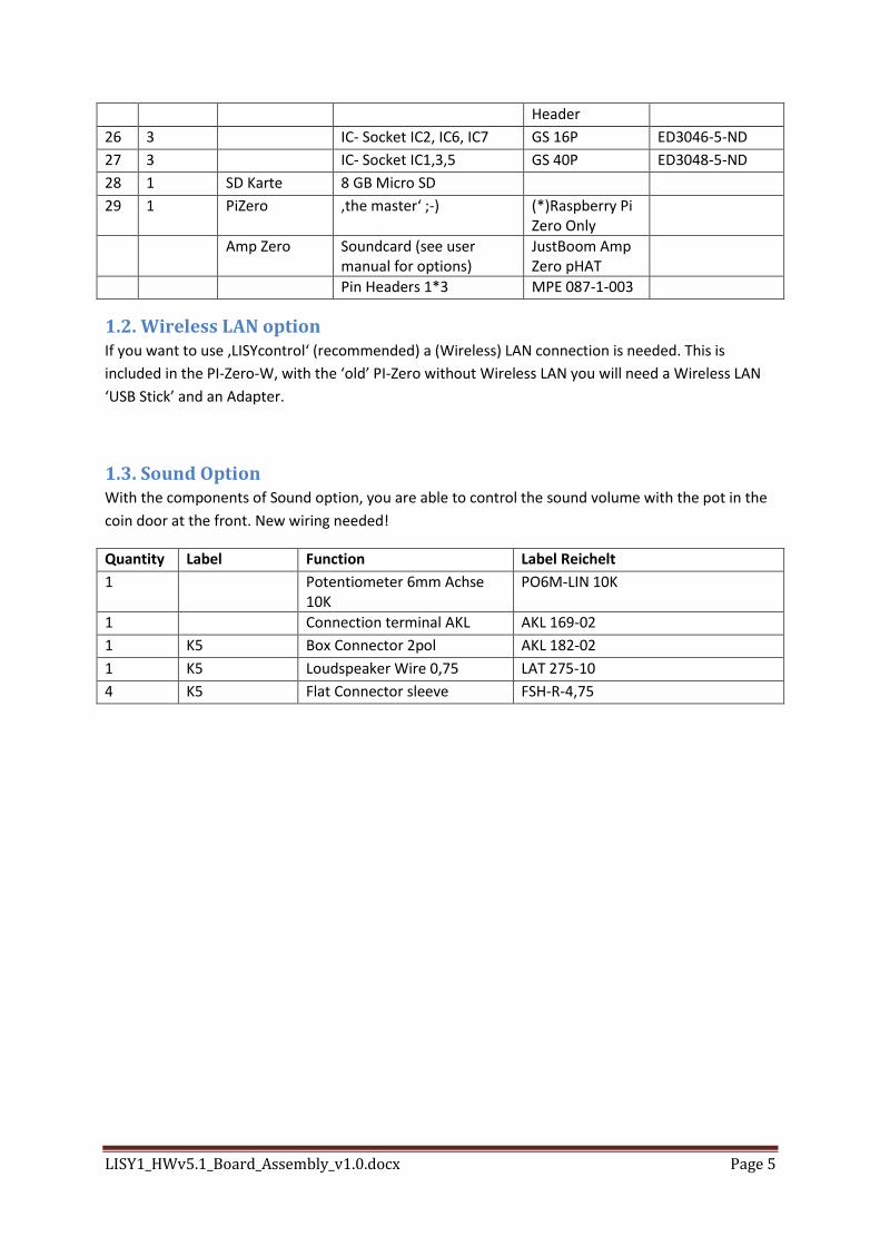
Header
26 3 IC- Socket IC2, IC6, IC7 GS 16P ED3046-5-ND
27 3 IC- Socket IC1,3,5 GS 40P ED3048-5-ND
28 1 SD Karte 8 GB Micro SD
29 1 PiZero ‚the master‘ ;-) (*)Raspberry Pi Zero Only
Amp Zero Soundcard (see user manual for options)
JustBoom Amp Zero pHAT
Pin Headers 1*3 MPE 087-1-003
1.2. Wireless LAN option If you want to use ‚LISYcontrol‘ (recommended) a (Wireless) LAN connection is needed. This is
included in the PI-Zero-W, with the ‘old’ PI-Zero without Wireless LAN you will need a Wireless LAN
‘USB Stick’ and an Adapter.
1.3. Sound Option With the components of Sound option, you are able to control the sound volume with the pot in the
coin door at the front. New wiring needed!
Quantity Label Function Label Reichelt
1 Potentiometer 6mm Achse 10K
PO6M-LIN 10K
1 Connection terminal AKL AKL 169-02
1 K5 Box Connector 2pol AKL 182-02
1 K5 Loudspeaker Wire 0,75 LAT 275-10
4 K5 Flat Connector sleeve FSH-R-4,75
LISY1_HWv5.1_Board_Assembly_v1.0.docx Page 6
2. Step by Step This Guide starts with the components with the least height and went from there step by step.
Please watch carefully the orientation of the components marked at the PCB. As I did some
‘optimization’ with the wiring (yes I did this by hand) you cannot expect that all parts have the same
orientation. Especially with the resistor Arrays take a second look to be on the save side and watch
the right position of ‘PIN1 ‘.
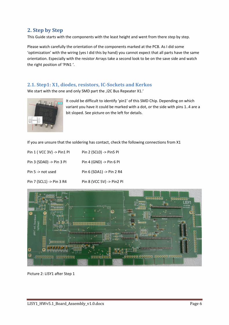
2.1. Step1: X1, diodes, resistors, IC-Sockets and Kerkos We start with the one and only SMD part the ‚I2C Bus Repeater X1.‘
It could be difficult to identify ‘pin1’ of this SMD Chip. Depending on which
variant you have it could be marked with a dot, or the side with pins 1..4 are a
bit sloped. See picture on the left for details.
If you are unsure that the soldering has contact, check the following connections from X1
Pin 1 ( VCC 3V) -> Pin1 PI Pin 2 (SCL0) -> Pin5 PI
Pin 3 (SDA0) -> Pin 3 PI Pin 4 (GND) -> Pin 6 PI
Pin 5 -> not used Pin 6 (SDA1) -> Pin 2 R4
Pin 7 (SCL1) -> Pin 3 R4 Pin 8 (VCC 5V) -> Pin2 PI
Picture 2: LISY1 after Step 1
LISY1_HWv5.1_Board_Assembly_v1.0.docx Page 7
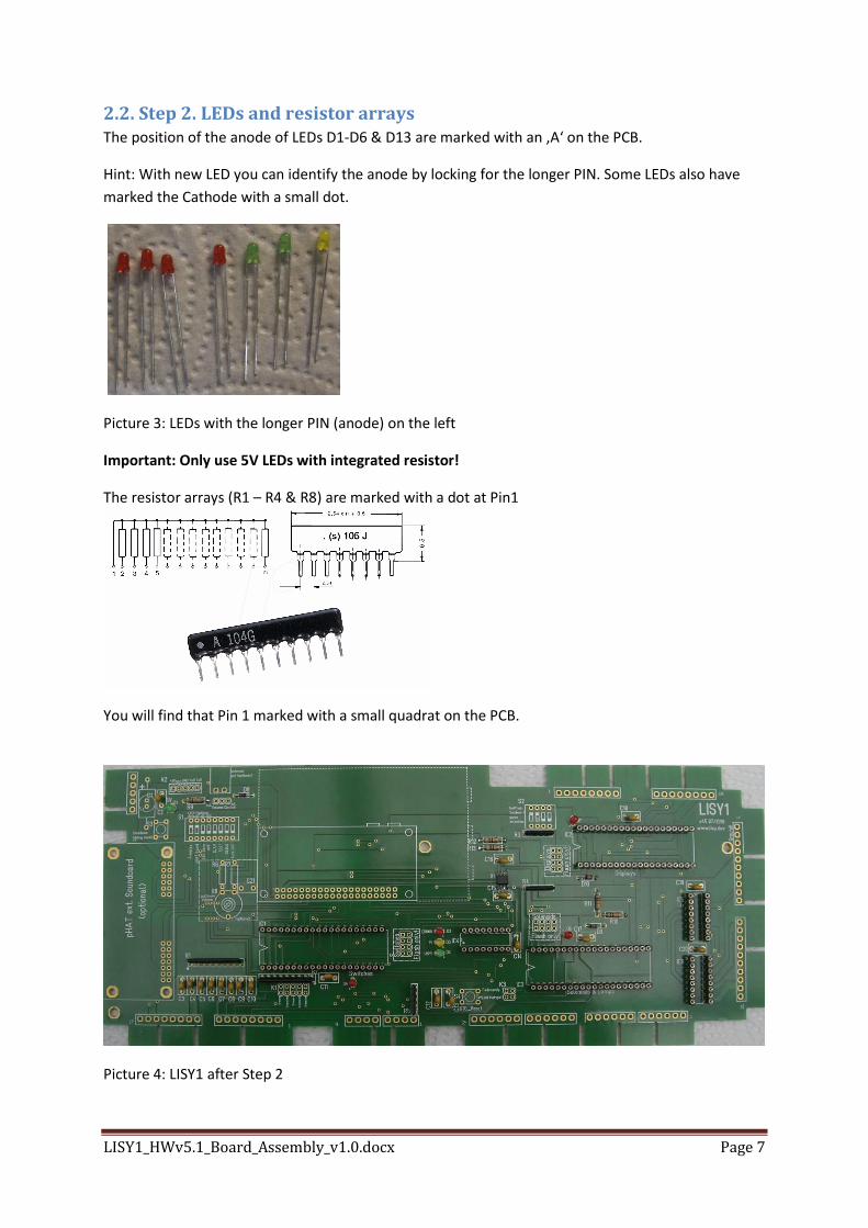
2.2. Step 2. LEDs and resistor arrays The position of the anode of LEDs D1-D6 & D13 are marked with an ‚A‘ on the PCB.
Hint: With new LED you can identify the anode by locking for the longer PIN. Some LEDs also have
marked the Cathode with a small dot.
Picture 3: LEDs with the longer PIN (anode) on the left
Important: Only use 5V LEDs with integrated resistor!
The resistor arrays (R1 – R4 & R8) are marked with a dot at Pin1
You will find that Pin 1 marked with a small quadrat on the PCB.
Picture 4: LISY1 after Step 2
LISY1_HWv5.1_Board_Assembly_v1.0.docx Page 8
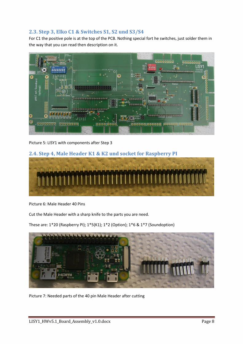
2.3. Step 3, Elko C1 & Switches S1, S2 und S3/S4 For C1 the positive pole is at the top of the PCB. Nothing special fort he switches, just solder them in
the way that you can read then description on it.
Picture 5: LISY1 with components after Step 3
2.4. Step 4, Male Header K1 & K2 und socket for Raspberry PI
Picture 6: Male Header 40 Pins
Cut the Male Header with a sharp knife to the parts you are need.
These are: 1*20 (Raspberry PI); 1*5(K1); 1*2 (Option); 1*6 & 1*7 (Soundoption)
Picture 7: Needed parts of the 40 pin Male Header after cutting
LISY1_HWv5.1_Board_Assembly_v1.0.docx Page 9
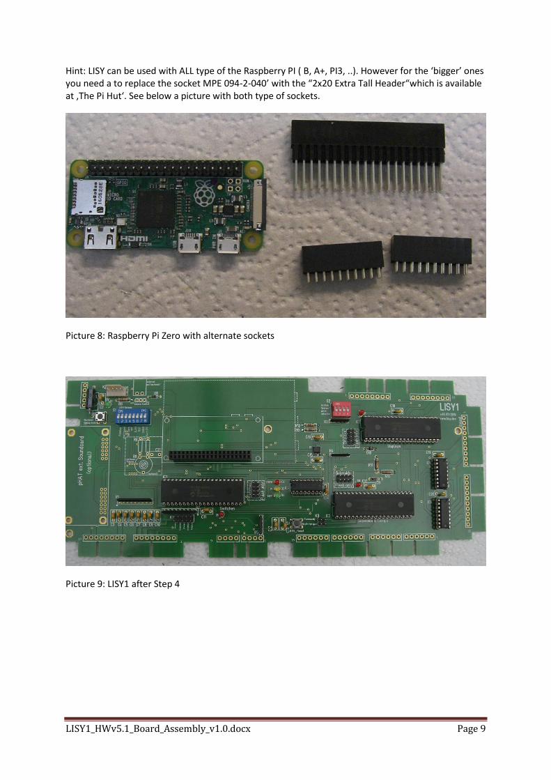
Hint: LISY can be used with ALL type of the Raspberry PI ( B, A+, PI3, ..). However for the ‘bigger’ ones you need a to replace the socket MPE 094-2-040’ with the “2x20 Extra Tall Header“which is available at ‚The Pi Hut‘. See below a picture with both type of sockets.
Picture 8: Raspberry Pi Zero with alternate sockets
Picture 9: LISY1 after Step 4

LISY1_HWv5.1_Board_Assembly_v1.0.docx Page 10
2.5. Step 5, Placement of all IC and the Raspberry PI After a final check of your soldering work, you can now place all the IC in the sockets. Again look
carefully on the orientation of the ICs.
For further instructions on how to place the ‘LISY’ image onto the SD card have a look at user
manual.
Picture 10: LISY1 after Step 5. ‘Ready to go’
LISY1_HWv5.1_Board_Assembly_v1.0.docx Page 11
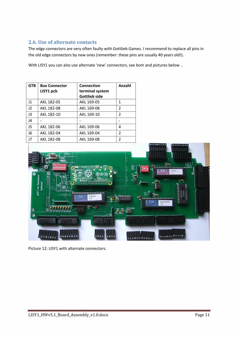
2.6. Use of alternate contacts The edge connectors are very often faulty with Gottlieb Games. I recommend to replace all pins in
the old edge connectors by new ones (remember: these pins are usually 40 years old!).
With LISY1 you can also use alternate ‘new’ connectors, see bom and pictures below ..
GTB Box Connector LISY1 pcb
Connection terminal system Gottlieb side
Anzahl
J1 AKL 182-05 AKL 169-05 1
J2 AKL 182-08 AKL 169-08 2
J3 AKL 182-10 AKL 169-10 2
J4 - - -
J5 AKL 182-06 AKL 169-06 4
J6 AKL 182-04 AKL 169-04 2
J7 AKL 182-08 AKL 169-08 2
Picture 12: LISY1 with alternate connectors.