Embed Size (px)
Citation preview

Radiocommunications Agency AY4398 8202CR1
© York EMC Services Ltd Page 2 of 19 Issue1
LIST OF TERMS AND ABBREVIATIONS 3
1 INTRODUCTION 4
1.1 Objectives of the overall study 4
2 DETAILS OF THE PRODUCTS PURCHASED FOR THIS STUDY 5
2.1 Introduction 5
2.2 Products based on the Switched Mode Power Supply Technology 5 2.2.1 Item 1: Mass produced SMPS for a PC 5 2.2.2 Item 2: Replacement PC SMPS 6 2.2.3 Item 3: DVD player 7 2.2.4 Item 4: Sky Digital Box 8 2.2.5 Item 5: Printer 9 2.2.6 Item 6: Plug-in Power supply 9
2.3 Products based on the Switched Electronic Load Controller Technology 10 2.3.1 Item 7: One way rotary dimmer 10 2.3.2 Item 8: Power corded Hammer Drill 11 2.3.3 Item 9: Separate speed transformer 12 2.3.4 Item 10: Courtesy Wall Light 13
3 BRIEF REVIEW OF THE SMPS TECHNOLOGY 14
3.1 Introduction 14
3.2 Basic Switched Mode Power Supply Circuit 14
3.3 The three type of basic circuit 15 3.3.1 The Buck type SMPS 15 3.3.2 The Boost type SMPS 15 3.3.3 The Buck-Boost type SMPS 16
4 BRIEF REVIEW OF THE SELC TECHNOLOGY 17
4.1 Introduction 17
4.2 Basics of Switched Electronic Load Controller 17
5 REFERENCES 19

Radiocommunications Agency AY4398 8202CR1
© York EMC Services Ltd Page 3 of 19 Issue1
List of Terms and Abbreviations
CENELEC Comité Européen de Normalisation Electrotechnique
CISPR Comité International Spécial des Perturbations Radioélectriques
COTS Commercial Off The Shelf
DIY Do It Yourself
EMC Electromagnetic Compatibility
EMI Electromagnetic Interference
EUT Equipment Under Test
ITT Invitation To Tender
MOSFET Metal-Oxide Semiconductor Field-Effect Transistor OATS Open Area Test Site
PC Personal Computer
RA Radiocommunications Agency
RF Radio Frequency
RTCG Radio Technology and Compatibility Group
SELCs Switched Electronic Load Controllers
SMPSs Switched Mode Power Supplies
YES York EMC Services Ltd

Radiocommunications Agency AY4398 8202CR1
© York EMC Services Ltd Page 4 of 19 Issue1
1 INTRODUCTION This document is part of the deliverables from York EMC Services Ltd. (YES) at the University of York to perform a study into the EMC emissions from off-load Switched Mode Power Supplies (SMPSs) and similar Switched Electronic Load Controller (SELC) devices. This deliverable is deliverable 1 and consists of a short interim report detailing the products purchased for this study based on SMPS and SELC technologies [1]
1.1 Objectives of the overall study i. Research the market in order to identify a range of products that are based on, or
contain, SMPS or SELC technology, and purchase a number of these products (around 10 in total) such that they represent the range available on the electrical goods market.
ii. Arrange with the Agency’s RTGG laboratory to test the purchased products for both conducted and radiated emissions over a range of agreed likely service conditions for the output load.
iii. Investigate and identify the circuit configurations of the items under test
iv. Produce guidelines or a Code of Practice for the SMPSs and SELCs that would enable the industry to improve the EMC performance of their products when in service.

Radiocommunications Agency AY4398 8202CR1
© York EMC Services Ltd Page 5 of 19 Issue1
2 DETAILS OF THE PRODUCTS PURCHASED FOR THIS STUDY 2.1 Introduction
This study is based on the investigation into the EMC emission from off-load Switched Mode Power Supplies (SMPSs) and similar Switched Electronic Load Controllers (SELCs).
It has been agreed with both the Radiocommunications Agency and York EMC Services Ltd that 6 items based on the SMPSs and 4 items based on the SELCs will be purchased and studied for this project [2].
The products purchased for this study were chosen to cover the widest range of applications while still remaining easily available for the general UK consumers. Those products were either purchased in local stores (DIY stores), ordered from the Internet, purchased through general catalogues or already available at YES.
2.2 Products based on the Switched Mode Power Supply Technology As agreed with the Radiocommunications Agency, 6 items based on the SMPS Technology have been purchased. Those are listed in Table 1.
Item Type of Product Characteristic Origin
1 Mass produced SMPS for a PC PSU-ATX 250 watts Catalogue
2 Replacement PC SMPS 250 watts, CE, Approved Catalogue
3 DVD player Internet
4 Sky Digital Box Already Available
5 Printer Stores
6 Plug-in Power supply Catalogue
Table 1: List of items based on the SMPS Technology.
2.2.1 Item 1: Mass produced SMPS for a PC This Switch Mode Power Supply is of type ATX1 250 watts (model number PW-250ATX) and has 6 outputs. The manufacturer is Power Win. Its electrical specifications are listed below.
AC Input 115V~/230V~, 10/5A 60/50Hz
DC output +3.3V +5V -5V +12V -12V +5V SB
Output current
0-15A 16-25A 0.3A 8-10A 1A 0-0.8A
Table 2: Electrical specification of item 1.
1 ATX is an industry-wide specification for a desktop computer's motherboard. ATX improves the motherboard design by taking the small AT motherboard (sometimes known as the "Baby AT" or BAT) that was an earlier industry standard and rotating by 90 degrees the layout of the microprocessor and expansion slots.

Radiocommunications Agency AY4398 8202CR1
© York EMC Services Ltd Page 6 of 19 Issue1
Figure 1: Picture of Mass-produced SMPS for a PC (Item 1).
2.2.2 Item 2: Replacement PC SMPS This Switch Mode Power Supply is of type ATX 12V 250 watts (model number MPT-251) and has 7 outputs. The manufacturer is Upguards Power Unit. Its electrical specifications are listed below.
AC Input 115V/230V~, 6/3A 60/50Hz
DC output +3.3V +5V -5V +12V -12V +5V SB
Output current
14A 25A 0.5A 13A 0.8A 3A
Table 3: Electrical specification of item 2.

Radiocommunications Agency AY4398 8202CR1
© York EMC Services Ltd Page 7 of 19 Issue1
Figure 2: Picture of Replacement PC SMPS (Item 2).
2.2.3 Item 3: DVD player A DVD player was purchased and its Switch Mode Power Supply will be tested for this work. The player was manufactured by Acoustic Solutions and the power supply was manufactured by Fairway (model number: VA3515). The electrical specifications of the SMPS are listed below.
AC Input 100V/240V~, 0.8A 60/50Hz
DC output +5V +12V -12V -27V AC output +3.5V
Output current
1.5A 0.4A 0.1A 5mA Output current
150mA
Table 4: Electrical specification of item 3.

Radiocommunications Agency AY4398 8202CR1
© York EMC Services Ltd Page 8 of 19 Issue1
Figure 3: Picture of the DVD player with its SMPS (Item 3).
2.2.4 Item 4: Sky Digital Box The SMPS of a Sky Digital Box will be tested for this work. The box has been manufactured by Pace. The electrical specifications of the SMPS are listed below.
AC Input 230V~, 0.3A 50Hz
DC output +3V +8V +5V -8V +20V +16V -33V
Table 5: Electrical specification of item 4.
Figure 4: Picture of the Sky Digital Box with its SMPS (Item 4).

Radiocommunications Agency AY4398 8202CR1
© York EMC Services Ltd Page 9 of 19 Issue1
2.2.5 Item 5: Printer A printer was purchased and its Switch Mode Power Supply will be tested for this work. The printer was manufactured by Lexmark and the power supply was manufactured by Delta Electronics (model number: ADP-12XB REV:B). The electrical specifications of the SMPS are listed below.
AC Input 220V-240V~, 1A 60/50Hz
DC Output 30V, 0.4A
Table 6: Electrical specification of item 5.
Figure 5: Picture of the Printer’s SMPS (Item 5).
2.2.6 Item 6: Plug-in Power supply This Plug-in Power Supply is of type 003 90489 (model number N2GFSW) and has a single output. The manufacturer is Egston. Its electrical specifications are listed below.
AC Input 100V-240V~, 0.18A 60/50Hz
DC Output 12VDC, 500mA
Table 7: Electrical specification of item 6.

Radiocommunications Agency AY4398 8202CR1
© York EMC Services Ltd Page 10 of 19 Issue1
Figure 6: Picture of the Plug-in Power supply (Item 6).
2.3 Products based on the Switched Electronic Load Controller Technology
As agreed with the Radiocommunications Agency, 4 items based on the SELC Technology have been purchased. Those are listed in Table 8.
Item Type of Product Characteristic Origin
7 One way rotary dimmer 250 watts Stores
8 Power corded Hammer Drill 760 watts Stores
9 Separate speed transformer 24VA output Catalogue
10 Courtesy Wall Light 60 watts Stores
Table 8: List of items based on the SELC Technology.
2.3.1 Item 7: One way rotary dimmer A one way rotary dimmer was purchased for the purpose of this study. The dimmer was manufactured by Doyle and Tratt Products Ltd. The electrical specifications of the Switch Electronic Load Controller are listed below.
AC Input 216V-253V~, 50Hz
Output Maximum load 250W and minimum load 40W
Table 9: Electrical specification of item 7.

Radiocommunications Agency AY4398 8202CR1
© York EMC Services Ltd Page 11 of 19 Issue1
Figure 7: Picture of the one way rotary dimmer (Item7).
2.3.2 Item 8: Power corded Hammer Drill A power corded hammer drill was purchased for the purpose of this study. The SELC is of type FA2-6/1BEK manufactured by Zhejiang Ruian Lida Electrical Appliance Co. Ltd. The electrical specifications of the Switch Electronic Load Controller are listed below.
AC Input 230-240V~, 50Hz
Output Maximum load 760W, 6A
Table 10: Electrical specification of item 8.

Radiocommunications Agency AY4398 8202CR1
© York EMC Services Ltd Page 12 of 19 Issue1
Figure 8: Picture of the Power corded hammer drill with its SELC (Item 8).
2.3.3 Item 9: Separate speed transformer A separate speed transformer was purchased for the purpose of this study (Model Number: MB730) and manufactured by Minicraft. The electrical specifications of the Switch Electronic Load Controller are listed below.
AC Input 230V~ 50Hz
Output 9-16V DC, 1.5A, 24VA
Table 11: Electrical specification of item 9.
Figure 9: Picture of the Separate speed controller with its SELC (Item 9).

Radiocommunications Agency AY4398 8202CR1
© York EMC Services Ltd Page 13 of 19 Issue1
2.3.4 Item 10: Courtesy Wall Light A courtesy wall light was purchased for the purpose of this study. The SELC enables the intensity to be tuned. The electrical specifications of the Switch Electronic Load Controller are listed below.
AC Input 230V~, 50Hz
Output Maximum load 60W.
Table 12:Electrical specification of item 10.
Figure 10: Picture of the Courtesy Wall Light with its SELC (Item 10).

Radiocommunications Agency AY4398 8202CR1
© York EMC Services Ltd Page 14 of 19 Issue1
3 BRIEF REVIEW OF THE SMPS TECHNOLOGY 3.1 Introduction
For many years, the world of power supply design is gradually moving from the use of linear power supplies to the more practical Switched Mode Power Supplies. Linear power supplies are known to have a poor efficiency (typically 30%), to be very heavy and also extremely large. Those characteristics, when compared to typical Switched Mode Power Supplies, make the SMPS a very strong candidate as power transformers. Advantages include efficiencies of between 70% and 80%, very compact size and light weight).
The most important section of the SMPS is the high frequency inverter, where the input supply is chopped at very high frequencies (up to 200kHz and current research is being pursued in the MHz region), then filtered and finally smoothed to produce the required output.
There is a wide choice of topologies of SMPSs, each of them with their specific characteristic (specific power application for example) but most of which are derivatives of the following basic circuits:
(i) Buck
(ii) Boost
(iii) Buck-Boost
For the purpose of this report, a description of the basic SMPS circuit will be presented with a short presentation of the three types of basic circuits (Buck, Boost, and Buck-Boost). A more detail summary of the various SMPS topologies will be presented in the final report [3].
3.2 Basic Switched Mode Power Supply Circuit
A SMPS, as seen from Figure 11, can be quite a complicated circuit. It is composed of various sections (enclosed in the rectangles) and each of them have their specific functions in the power conversion.
When a SMPS is fed from a 50/60Hz main supply, the AC supply is first rectified and then filtered by the input reservoir which then produces a “DC” output (In the case of a AC to DC
Figure 11: Basic Switched Mode Power Supply block diagram
Radiocommunications Agency AY4398 8202CR1
© York EMC Services Ltd Page 15 of 19 Issue1
SMPS). The input capacitances are usually of high values to hold up the supply in the event of a large drop in the main supply. The unregulated “DC” is then fed to the high frequency switching section, where semiconductors devices such as MOSFETs or Bipolar transistors switch the input voltage across the primary of the transformer (switching frequency from 20 to 200kHz).
Hence, a voltage pulse train of suitable magnitude and duty ratio appears on the transformer secondaries which is then rectified and smoothed by the output filter (composed of either capacitor/inductor arrangement).
The regulation of the output stability is achieved by the control/feedback block. The output voltage is compared to an accurate reference supply, and the error voltage produced by the comparator is used by dedicated control logic to terminate the drive pulse to the main power switch/switches at the correct instance. With a correct design, this SMPS will provide a very stable DC output supply.
3.3 The three type of basic circuit The majority of the topologies used in the SMPS are derived from these three non-isolated (without power transformer) versions called the Buck, the Boost and the Buck-Boost. These are presented in the following sections.
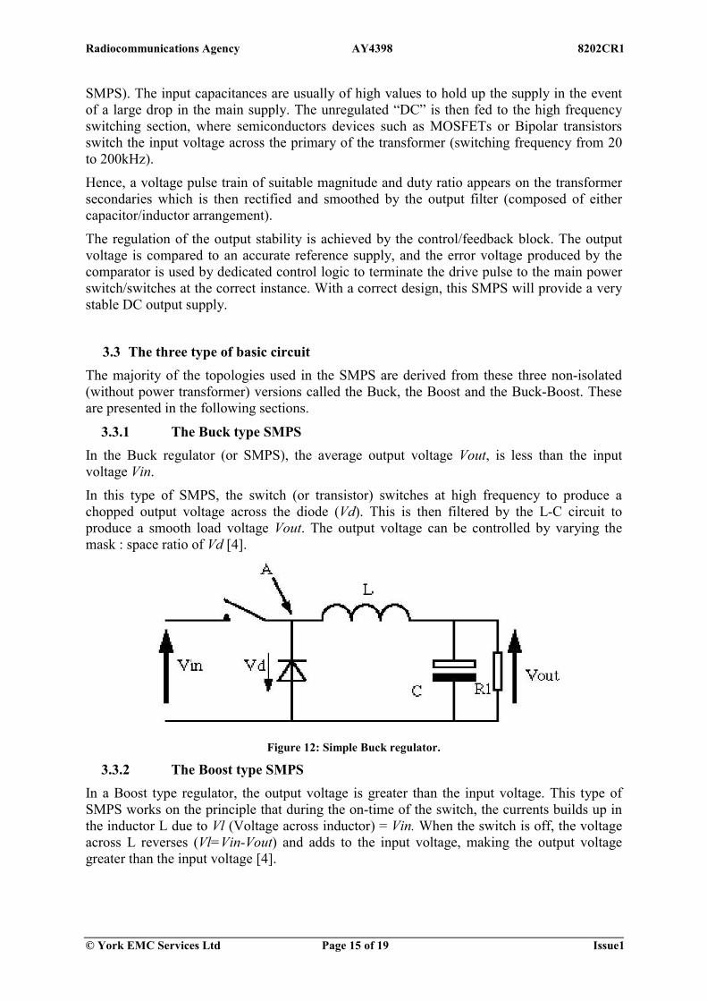
3.3.1 The Buck type SMPS In the Buck regulator (or SMPS), the average output voltage Vout, is less than the input voltage Vin.
In this type of SMPS, the switch (or transistor) switches at high frequency to produce a chopped output voltage across the diode (Vd). This is then filtered by the L-C circuit to produce a smooth load voltage Vout. The output voltage can be controlled by varying the mask : space ratio of Vd [4].
Figure 12: Simple Buck regulator.
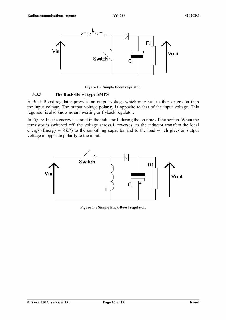
3.3.2 The Boost type SMPS In a Boost type regulator, the output voltage is greater than the input voltage. This type of SMPS works on the principle that during the on-time of the switch, the currents builds up in the inductor L due to Vl (Voltage across inductor) = Vin. When the switch is off, the voltage across L reverses (Vl=Vin-Vout) and adds to the input voltage, making the output voltage greater than the input voltage [4].
Radiocommunications Agency AY4398 8202CR1
© York EMC Services Ltd Page 16 of 19 Issue1
Figure 13: Simple Boost regulator.
3.3.3 The Buck-Boost type SMPS A Buck-Boost regulator provides an output voltage which may be less than or greater than the input voltage. The output voltage polarity is opposite to that of the input voltage. This regulator is also know as an inverting or flyback regulator.
In Figure 14, the energy is stored in the inductor L during the on time of the switch. When the transistor is switched off, the voltage across L reverses, as the inductor transfers the local energy (Energy = ½LI2) to the smoothing capacitor and to the load which gives an output voltage in opposite polarity to the input.
Figure 14: Simple Buck-Boost regulator.
Radiocommunications Agency AY4398 8202CR1
© York EMC Services Ltd Page 17 of 19 Issue1
4 BRIEF REVIEW OF THE SELC TECHNOLOGY 4.1 Introduction
SELCs are becoming very common in the residential, commercial and light industrial environment. The technology of SELC is based on a solid state dimmer which works by varying the “duty cycle” (on/off time) of the full AC voltage that is applied to the device which is being controlled.and are either based on thyristors or triac (modern thyristor).
4.2 Basics of Switched Electronic Load Controller Thyristor or triac are usually off but can be triggered on by a low current pulse to a gate. Once triggered on, they remain on until the current flowing through the main terminals of the device goes to zero.
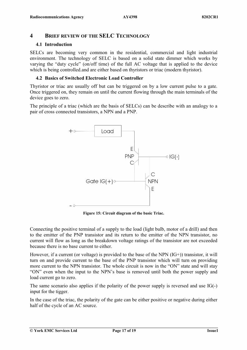
The principle of a triac (which are the basis of SELCs) can be describe with an analogy to a pair of cross connected transistors, a NPN and a PNP.
Figure 15: Circuit diagram of the basic Triac.
Connecting the positive terminal of a supply to the load (light bulb, motor of a drill) and then to the emitter of the PNP transistor and its return to the emitter of the NPN transistor, no current will flow as long as the breakdown voltage ratings of the transistor are not exceeded because there is no base current to either.
However, if a current (or voltage) is provided to the base of the NPN (IG+)) transistor, it will turn on and provide current to the base of the PNP transistor which will turn on providing more current to the NPN transistor. The whole circuit is now in the “ON” state and will stay “ON” even when the input to the NPN’s base is removed until both the power supply and load current go to zero.
The same scenario also applies if the polarity of the power supply is reversed and use IG(-) input for the tigger.
In the case of the triac, the polarity of the gate can be either positive or negative during either half of the cycle of an AC source.

Radiocommunications Agency AY4398 8202CR1
© York EMC Services Ltd Page 18 of 19 Issue1
Figure 16: “ON/OFF” triggering of the duty cycle.

Radiocommunications Agency AY4398 8202CR1
© York EMC Services Ltd Page 19 of 19 Issue1
5 References [1] Tender for performing an investigation into the EMC emissions from off-load Switched Mode Power Supplies (SMPSs) and similar Switched Electronic Load Controllers (SELCs) – Contract AY 4398 – York EMC document Number 8130CR1.
[2] Meeting at the Radiocommunications Agency offices on the 17/12/2002 between B. Martin (RA), J. Airs (RA), L. McCormack (YES) and D. Bozec (YES).
[3] Final report on the “Tender for performing an investigation into the EMC emissions from off-load Switched Mode Power Supplies (SMPSs) and similar Switched Electronic Load Controllers (SELCs) – Contract AY 4398” to be presented by YES to the Radiocommunications Agency.
[4] Switched Mode Power Supplies – Design and Construction – Second Edition, H.W. Whittington, B.W. Flynn and D.E. Macpherson, Research Studies Press Ltd.


![Abbreviations List[1]](https://img.pdfslide.us/doc/110x75/577cc4991a28aba71199ddf5/abbreviations-list1.jpg)