Embed Size (px)
Citation preview
List of Publications:
1. Shaofeng Ran, Xinhua Zong, Dufei Fang, Benjamin S. Hsiao, Benjamin Chu and Roger A. Phillips, “Structural and Morphological Studies of Isotactic Polypropylene Fibers during Heat/Draw Deformation by in-Situ Synchrotron SAXS/WAXD,” Macromolecules, 34, 2569-2578 (2001).
2. Francisco J. Medellin-Rodriguez, Christian Burger, Benjamin S. Hsiao, Benjamin Chu, Richard Vaia and Shawn Phillips, “Time-Resolved Shear Behavior of End-Tethered Nylon 6-Clay Nanocomposites Followed by Non-Isothermal Crystallization,” Polymer, 42, 9015-9023 (2001).
3. Shaofeng Ran, Xinhua Zong, Dufei Fang, Benjamin S. Hsiao, Benjamin Chu, Philip M. Cunniff and Roger A. Phillips, “Studies of the Mesophase Development in Polymeric Fibers during Deformation by Synchrotron SAXS/WAXD,” J. Mat. Sci. Papers, 36, 3071-3077 (2001).
4. Benjamin Chu and Benjamin S. Hsiao, “Small-Angle X-Ray Scattering of Polymers”, Chem. Rev., 101, 1727-1761 (2001). 5. Benjamin Chu, “Possible Application of Laser Light Scattering to Remote Sensing,” in Remote Sensing 2000: From Laboratory Spectroscopy to Remote Sensed Spectra of Terrestrial Ecosystems, ed. R. S. Muttiah, Kluwer Academic Publishers, Dordrecht, The Netherlands, Chap. 3, pp.61-83 (2002).
6. Shaofeng Ran, Christian Burger, Dufei Fang, Xinhua Zong, Sharon Cruz, Benjamin Chu, Benjamin S. Hsiao, Robert A. Bubeck, Kazuyuki Yabuki, Yoshihiko Teramoto, David C. Martin, Michael A. Johnson and Philip M. Cunniff, “In-Situ Synchrotron WAXD/SAXS Studies of Structural Development during PBO/PPA Solution Spinning,” Macromolecules, 35, 433-349 (2002).
7. Christian Burger, Shuiqin Zhou and Benjamin Chu, “Nanostructures in Polyelectrolyte-Surfactant Complexes and Their Applications” in Handbook of Polyelectrolytes and Their Applications, Vol. 3, Eds. S. Tripathy, J. Kumar and H. S. Nalwa, Amer. Sci. Pub., (2002) Chapter 7, pp.125-141. 8. Benjamin S. Hsiao and Benjamin Chu, “Chemical Applications of Small Angle Scattering,” in Chemical Applications of Synchrotron Radiation, Part II: X-Ray Applications, ed. T. K. Sham, Ed., World Scientific Publishing Co. Pte. Ltd., Singapore, Chap. 17, pp. 799-849 (2002). 9. Michael Gelfer, Hyun H. Song, Lizhi Liu, Carlos Avila-Orta, Ling Yang, Mayu Si, Benjamin S. Hsiao, Benjamin Chu, Miriam Rafailovich and Andy H. Tsou, “Manipulating the Microstructure and Rheology in Polymer-Organoclay Composites,” Polym. Engr. and Sci., 42, 1841-1851 (2002). 10. Xinhua Zong, Kwangsok Kim, Dufei Fang, Shaofeng Ran, Benjamin S. Hsiao and Benjamin Chu, “Structure and process relationship of elestrospun bioabsorbable nanofiber membranes,” Polymer, 43, 4403-4412 (2002). 11. Shaofeng Ran, Christian Burger, Dufei Fang, Xinhua Zong, Benjamin Chu, Benjamin S. Hsiao, Yasuo Ohta, Kazuyuki Yabuki and Philip M. Cunniff, “A Synchrotron WAXD Study on the Early Stages of the Coagulation Process during PBO Fiber Spinning,” Macromolecules, Communication, 35, 9851-9853 (2002).
REPORT DOCUMENTATION PAGE (SF298)
(Continuation Sheet)
12. Shaofeng Ran, Zhigang Wang, Christian Burger, Benjamin Chu and Benjamin S. Hsiao, “Mesophase as the Precursor for Strain-Induced Crystallization in Amorphous Poly(ethylene terephthalate) Film,” Macromolecules, 35, 10102-10107 (2002).
13. Shaofeng Ran, Dufei Fang, Shigeyuki Toki, Benjamin S. Hsiao and Benjamin Chu, “Combined Techniques of Raman Spectroscopy and Synchrotron X-ray Diffraction for In-Situ Study of Anisotropic System: Example of Polymer Under Deformation,” Rev. Sci. Instrum., 74, 3087-3092 (2003). 14. Kwangsok Kim, Meiki Yu, Xinhua Zong, Jonathan Chiu, Dufei Fang, Young-Soo Seo, Benjamin
S. Hsiao, Benjamin Chu and Michael Hadjiargyrou, “Control of Degradation Rate and Hydrophilicity in Electrospun Non-Woven Poly(D,L-lactide) Nanofiber Scaffolds for Biomedical Applications,” Biomaterials, 24, 4977-4985 (2003).
15. Christian Burger, Shaofeng Ran, Dufei Fang, David Cookson, Kazuyuki Yabuki, Yoshihiko Teramoto, Philip M. Cunniff, P. James Viccaro, Benjamin S. Hsiao and Benjamin Chu, “Time- Resolved Structural Studies in Fiber Processing,” Macromol. Symp., accepted for publication. 16. Shaofeng Ran, Christian Burger, Igors Sics, Kyunghwan Yoon, Dufei Fang, Kwangsok Kim, Carlos Avila-Orta, Benjamin Chu, Benjamin S. Hsiao, David Cookson, David Shultz, Myungae Lee and Yasuo Ohta, “Synchrotron SAXS/WAXD Studies during Melt Spinning of Modified Carbon Nanofiber and Isotactic Polypropylene Nanocomposite,” J. Coll. Polym. Sci., submitted for publication.
(2) Scientific Personnel Prof. Ben Chu - Principal Investigator Dr. Shaofeng Ran - Postdoctoral Associate Dr. Igors Sics - Postdoctoral Associate (50%) Dr. Dufei Fang - Sr. Research Scientist (10%) Mr. Hongjun Cai - Graduate Student Kyunghwan Yoon - Graduate Student Ms. Jane Wainio - Project Staff Asst. (20%) (3) Report of Inventions - New Technology Disclosures:
1) High Strength Nanocomposite Fibers and Films Containing Poly(p-phenylene terephthalamide), poly{2,6-diimidazo[4,5-b:4’5’-e]pyridinylene-1,4(2,5-dihydroxy) phenylene} nanocomposite fibers and films. Inventors: Benjamin Chu, Benjamin S. Hsiao and Iwao Ojima. Disclosure Date: August 28, 2003. Ref. #R-7696.
2) Nanocomposite Fibers and Films Containing Polyolefin and Surface-Modified Carbon Nanofibers.
Inventors: Benjamin Chu and Benjamin S. Hsiao. Disclosure Date: August 28, 2003. Ref. #R-7695.
Statement of Problem Studied
Although our ARO funds came to an end, we concentrated our remaining efforts toward the future by
undertaking a detailed study on the small angle X-ray scattering and wide angle X-ray diffraction measurements of nano-composite fibers of isotactic polypropylene and modified carbon nanofiber. The results were most encouraging.
Summary of the Most Important Results The structural development of a nanocomposite, containing 95 wt% isotactic polypropylene (iPP) and 5 wt% modified carbon nanofiber (MCNF), during fiber spinning was investigated by in-situ synchrotron small angle X-ray scattering (SAXS) and wide angle X-ray diffraction (WAXD) techniques. The key points to the success in fabricating this nanocomposite fiber are two-fold: A proper chemical modification of the surface of the CNF, making it compatible with iPP and the appropriate blending of the two components before fiber spinning. With only 5% MCNF, we have already achieved much higher tensile strength (~80% increase), modulus (~60% increase), and longer elongation to break (~65% increase). The remarkable increase in the elongation to break is especially interesting, as these types of fibers will become very tough. Based on the preliminary results, we submitted two technical disclosures to the University Technology Transfer Office on August 27, 2003. Both are being prepared for patent applications.
New Research:
In-Situ Synchrotron SAXS/WAXD Studies during Melt Spinning of Modified Carbon Nanofiber and Isotactic Polypropylene Nanocomposite
INTRODUCTION
Single-walled carbon nanotubes (SWNTs) and multi-walled carbon nanotubes (MWNTs) have been
suggested as good nanofillers to create a new class of high performance polymers and fibers due to their high strength, lightweight, small diameters (∼ 1 nm for SWNTs and 2 ∼ 50 nm for MWNTs) and large aspect ratios
[1]. In particular, carbon nanotube-based nanocomposites may offer new opportunities for applications because of the highly anisotropic electronic properties, improved thermal conductivity (higher than diamond) and superior mechanical properties (that surpass the stiffness and strength of any known polymer materials) of carbon nanotubes [2]. However, with the current production technology, carbon nanotubes are still too expensive for practical use. An alternative carbon nanotube-based nanofiller is the much less expensive vapor grown carbon nanofibers (CNFs), which have an average diameter of 50∼200 nm, bridging the gap between the diameter of conventional carbon fibers (7∼10 µm) and those of SWNTs and MWNTs. Carbon nanofibers can be produced on a relatively large scale by the catalytic decomposition of certain hydrocarbons on small metal particles such as iron, cobalt, nickel, and some of their alloys [3-6].
Recently, several polymer nanocomposites based on CNFs have been demonstrated in the literatures,
including the systems of isotactic polypropylene (iPP) [7,8], polycarbonate (PC) [9] and Nylon [10]. In these studies, while improvements of mechanical properties were seen, the major hurdle appeared to be the fine balance between the preparation schemes and the exfoliation of CNFs in the polymer. The practical melt mixing method is not always effective to disperse the entangled carbon nanofibers, which often forms a dense and robust network structure at high CNF concentrations.
Chemical functionalization is an especially attractive route to increase the solubility of carbon nanotubes in the polymer matrix. Such nanocomposites can also be processed by using conventional melt processing methods. Recently, different functionalization schemes have been reviewed by Hirsch [11], including defect-group functionalization [12-14], covalent sidewall functionalization [13,15], non-covalent exohedral [16] and endohedral functionalization [17]. However, functionalization of CNFs to improve the miscibility between CNFs and polyolefins by melt mixing has never been reported.
In this study, the surface of CNFs was modified by in-situ polymerization of olefin segments to increase the interfacial compatibility between CNFs and iPP. Nanocomposites containing exfoliated modified carbon nanofibers (MCNF) in iPP were prepared by melt blending, which was verified by scanning electronic microscopy (SEM). The structural development of the nanocomposite fiber during spinning was followed by in-situ synchrotron small-angle X-ray scattering (SAXS) and wide-angle X-ray diffraction (WAXD) techniques, which have recently been developed in our laboratory [18]. Mechanical properties including the Young’s modulus, tensile strength and elongation-to-break of the composite fiber were also evaluated, which showed notable improvements over those of iPP fibers with no MCNFs. EXPERIMENTAL
Materials
The iPP sample was an experimental resin provided by ExxonMobil Chemical Company. The carbon
nanofiber (PR-24-HHT) was obtained from Pyrograf Products, Inc. The material underwent a thermal treatment to remove any non-carbon components. The typical morphology of the as-received CNFs is shown in Figure 1, which has an average diameter of 70 nm and a length of 50-100 µm (the aspect ratio thus is about 1000). The CNFs showed hollow cores with open end. We found that the as-received CNFs were clean and free of any remaining catalyst. No additional purification procedures were taken in this study.
Surface Modifications of CNFs
All reagents were obtained from Aldrich, and solvents were obtained from Fisher Scientific. Styrene and
triethylamine (TEA) were distilled with CaH2. Tetrahydrofuran (THF) was dried by sodium under nitrogen. Other reagents were used without purification. Silica gel for flash chromatography was Merck grade 60 (70-230). Two polymerization initiators, 1-(benzyloxy)-2-phenyl-2-(2’,2’,6’,6’-tetramethyl-1’-piperidinyloxy) ethane (TEMPO-ester) and 1-hydroxy-2-phenyl-2-(2’,2’, 6’,6’-tetramethyl-1’-piperidinyloxy)ethane (TEMPO-alcohol), were synthesized based on the reported procedure 19. The overall synthetic schemes are summarized as follows, but the details of the synthesis and characterization of MCNFs will be reported later.
(1) Acid group generation on carbon nanofibers. The surface acidic groups (carboxylic acid and
hydroxyl) on the carbon nanofibers were generated by the oxidation reaction using potassium perchlorate/sulfuric acid solution (e.g. 2 gm of carbon nanofibers in KClO3 solution (i.e., 2 gm of KClO3 in 100 ml of concentrated H2SO4)) at room temperature 20. The carbon nanofiber suspension was filtered by 0.2-µm filter and washed with de-ionized water and methanol. The filtered nanofibers were dried in vacuo at 70 ºC.
(2) Attachment of radical initiator to carbon nanofiber surfaces. The oxidized CNFs were refluxed
in thionyl chloride for 24 hours at 65 ºC. Subsequently, the thionyl chloride was removed by distillation. The dried acyl chloride modified CNFs were reacted with TEMPO-alcohol in dry THF using TEA as a catalyst at 75 ºC for 2 days. The reaction mixture was then washed with water and THF, and then dried in vacuo at 70 ºC.
(3) Surface free-radical polymerization. The initiator-attached CNFs were mixed with isoprene (the mole ratio of initiator to monomer was about 1 : 480) 21. The mixture was heated at 130 ºC for 10 hours. After polymerization, the grafted CNFs were washed with methanol and dried in vacuo at 70 ºC.
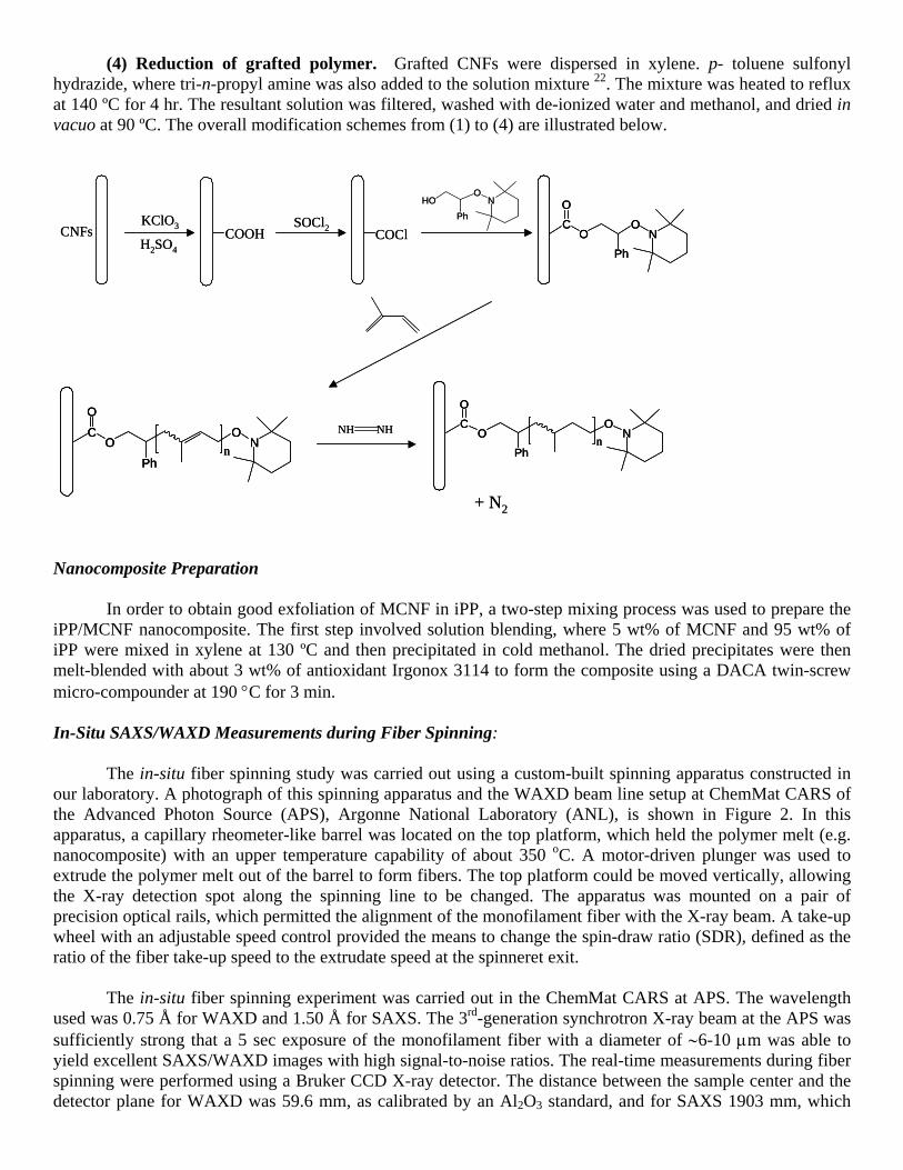
(4) Reduction of grafted polymer. Grafted CNFs were dispersed in xylene. p- toluene sulfonyl hydrazide, where tri-n-propyl amine was also added to the solution mixture 22. The mixture was heated to reflux at 140 ºC for 4 hr. The resultant solution was filtered, washed with de-ionized water and methanol, and dried in vacuo at 90 ºC. The overall modification schemes from (1) to (4) are illustrated below.
Nanocomposite Preparation
In order to obtain good exfoliation of MCNF in iPP, a two-step mixing process was used to prepare the iPP/MCNF nanocomposite. The first step involved solution blending, where 5 wt% of MCNF and 95 wt% of iPP were mixed in xylene at 130 ºC and then precipitated in cold methanol. The dried precipitates were then melt-blended with about 3 wt% of antioxidant Irgonox 3114 to form the composite using a DACA twin-screw micro-compounder at 190 °C for 3 min.
In-Situ SAXS/WAXD Measurements during Fiber Spinning:
The in-situ fiber spinning study was carried out using a custom-built spinning apparatus constructed in our laboratory. A photograph of this spinning apparatus and the WAXD beam line setup at ChemMat CARS of the Advanced Photon Source (APS), Argonne National Laboratory (ANL), is shown in Figure 2. In this apparatus, a capillary rheometer-like barrel was located on the top platform, which held the polymer melt (e.g. nanocomposite) with an upper temperature capability of about 350 oC. A motor-driven plunger was used to extrude the polymer melt out of the barrel to form fibers. The top platform could be moved vertically, allowing the X-ray detection spot along the spinning line to be changed. The apparatus was mounted on a pair of precision optical rails, which permitted the alignment of the monofilament fiber with the X-ray beam. A take-up wheel with an adjustable speed control provided the means to change the spin-draw ratio (SDR), defined as the ratio of the fiber take-up speed to the extrudate speed at the spinneret exit.
The in-situ fiber spinning experiment was carried out in the ChemMat CARS at APS. The wavelength
used was 0.75 Å for WAXD and 1.50 Å for SAXS. The 3rd-generation synchrotron X-ray beam at the APS was sufficiently strong that a 5 sec exposure of the monofilament fiber with a diameter of ∼6-10 µm was able to yield excellent SAXS/WAXD images with high signal-to-noise ratios. The real-time measurements during fiber spinning were performed using a Bruker CCD X-ray detector. The distance between the sample center and the detector plane for WAXD was 59.6 mm, as calibrated by an Al2O3 standard, and for SAXS 1903 mm, which
CNFsKClO3
H2SO4COOH
SOCl2 COCl NO
Ph
OC
O
NO
Ph
OC
O
nN
O
Ph
OC
O
n
NO
Ph
HO
NH NH
+ N2
CNFsKClO3
H2SO4COOH
SOCl2 COCl NO
Ph
OC
O
NO
Ph
OC
O
NO
Ph
OC
O
n NO
Ph
OC
O
nN
O
Ph
OC
O
nN
O
Ph
OC
O
n
NO
Ph
HO
NH NH
+ N2
was calibrated by a collagen standard. The melt-spinning study of iPP/MCNF was carried out at 195 °C. The extrusion speed at the spinneret was fixed at 5.2 mm/sec.
SEM Measurements
The surface and the cross-section of the iPP/MCNF nanocomposite and pure iPP fibers were studied by scanning electron microscopy (SEM, LEO 1550). The SEM instrument was equipped with a Schottky field-emission gun (10 KV) and a Robinson backscatter detector. The cross-section of the fibers was obtained by fracturing the fibers in liquid nitrogen. All samples received 30 s of gold coating to minimize the charging effect.
Mechanical Properties Measurements
A bundle of spun fibers (about 10 filaments) with SDR of 50.0 were used to test the mechanical properties using an Instron stretching apparatus (model 4410). The testing was performed at a constant speed of 20 mm/min at room temperature. The tensile strength, Young’s modulus and the elongation-to-break of the iPP/MCNF nanocomposite and pure iPP fibers were determined. RESULTS AND DISCUSSION
Figure 3 shows selected two-dimensional (2D) WAXD patterns of the spun iPP/MCNF composite fiber
at different spin-draw ratios after correction of the air scattering. These patterns showed well-resolved diffraction peaks, typical of the α-form iPP crystals. With increasing spin-draw ratios, the azimuthal spreads of the reflection peaks became much narrower, indicating that the crystal orientation increased. Since the diffraction peaks of the pure carbon nanofiber are very close to some of the iPP reflections, it is not easy to distinguish the MCNF from iPP in the composite WAXD patterns at low spin-draw ratios. Fortunately, at high spin-draw ratios (i.e., SDR = 31 and 60), the 002 reflection of CNF was clearly observed because of the difference in the orientation between iPP and MCNF structures. It should be noted that we used the designation “002” only because of its resemblance to the graphite structure. The implied “ABA” stacking sequence of the carbon layers is usually not found in MWNTs or CNFs. It was seen because MCNF was only partially oriented in the nanocomposite at high spin-draw ratios.
One of the advantages in conducting the synchrotron experiments at ChemMat Cars/APS/ANL is that
the X-ray wavelength could be easily adjusted. The relatively short wavelength (0.75 Å) chosen in this work allowed the second scattering ring of CNF (reflection (10)) to be seen, although it was very weak. It was interesting to note that the orientation of the iPP reflection (040) was much higher than that of the reflection (110) at low spin-draw ratios. At high spin-draw ratios, the orientation of (110) and (040) were almost the same, which indicated that the orientation of (110) and (040) developed differently during fiber spinning. The calculation of the Hermans’ orientation factor P2 of reflections (110) and (040) confirmed this observation. The chain axis orientation in the spun fiber was calculated mathematically by using the following equations [23].
where Z represents the direction of the fiber axis and c indicates the molecule chain direction.
Figure 4 shows the calculated Hermans’ orientation factor P2 for both nanocomposite fiber and pure iPP
fiber. It was found that at low spin-draw ratios, the 5 wt% MCNF reinforced iPP nanocomposite fiber had much higher orientation than the control iPP fiber, indicating that MCNF facilitated the orientation of iPP chains at low spin-draw ratios, which could be due to the reduction of local melt viscosity during spinning. When the
2
1cos3)(cos
cos901.0cos099.11cos
,2
,2
,0402
,1102
,2
−=
−−=
ZcZc
ZZZc
Pφ
φ
φφφ
spin-draw ratios were high, the orientations of the nanocomposite fiber and the pure iPP fiber were
almost the same, which all reached a very high degree of orientation (i.e., P2 = 0.9 with P2 = 1.0 indicating perfect orientation). Our explanation is that the rigid short carbon nanofibers, which are easily oriented at low spin-draw ratio, can act as anisotropic nucleating sites to enhance the alignment of iPP chains along the drawing direction. In addition, the very short olefin chains on the MCNF surface may reduce the local viscosity of the matrix around the vicinity carbon nanofibers. At high spin-draw ratios, all of the iPP chains are highly oriented and the nucleating effects of the carbon nanofibers are no longer significant.
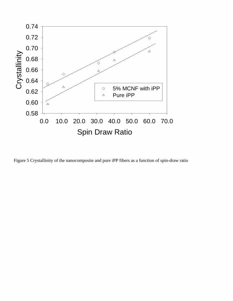
One dimensional (1D) intensity profiles were extracted from 2D WAXD patterns using a spherical averaging method, taking into account of the proper weighting factor with simple fiber symmetry assumption. These intensity profiles were plotted as a function of the absolute value of the scattering vector s =2sin(θ)/λ (λ and 2θ represent wavelength and scattering angle, respectively), from which the crystallinity was estimated using a peak fitting procedure to deconvolute the crystalline peaks and amorphous background. Figure 5 shows the calculated crystallinity of the spun nanocomposite fibers and pure iPP fibers as a function of spin-draw ratio. It was found that the crystallinity of both nanocomposite and control iPP fibers all increased almost linearly with the spin-draw ratio, which is probably due to the strain-induced crystallization. It was seen that the crystallinity of the nanocomposite fiber was about 6% larger than that of the control iPP fiber, suggesting that the modified carbon nanofibers acted as heterogeneous nucleating sites for iPP crystallization.
Figure 6 shows the 2D SAXS patterns of the composite fibers at different spin-draw ratios. The patterns
showed a meridionally aligned two-point pattern, indicating the presence of a lamellar structure of iPP with the lamellar normal preferentially aligned with the fiber axis. A 2nd order of the scattering peak was clearly visible in the higher s range, which requires a certain amount of long-range order of the lamellar structures in the fiber. The long periods (d = 1/s) were obtained from the Lorentz-corrected peak maxima.
Figure 7 illustrates the obtained long periods of the nanocomposite and pure iPP fibers as a function of
the spin-draw ratio. It was found that the nanocomposite fiber formed a larger long period at low spin-draw ratios. At high spin-draw ratios, the long period of the composite fiber was similar to that of the pure iPP. We think that at low spin-draw ratios, relatively larger iPP lamellae are formed around the carbon nanofibers because MCNFs are oriented first and can act as nuclei. At high spin-draw ratios, however, the nucleating effect of MCNFs is no longer dominant as the iPP chains can also be stretching and form even more effective nuclei.
On the equator, the pure iPP fiber showed a typical equatorial streak due to a fibrillar superstructure (e.g.
the shish-kebab structure) while the nanocomposite fiber showed a strong diamond shaped SAXS pattern. The latter is most likely due to the oriented hollow cores of the CNFs, which provide the greater source of density contrast at the present length scales than the iPP superstructure.
A bundle of the spun fibers (pure and nanocomposite) with SDR of 50.0 were used to measure the
tensile mechanical properties. Table 1 lists the tensile strength, Young’s modulus and elongation-to-break of the nanocomposite and pure iPP fibers. It was found that the nanocomposite fiber with 5% MCNF had much higher tensile strength, modulus and elongation-to-break values. It was evident that the surface modification of carbon nanofibers successfully increased the interactions between carbon nanofibers and the iPP matrix, thereby enhancing the homogenous dispersion of the carbon nanofibers in the matrix and the mechanical performance. The morphological studies of the composite fiber confirmed this finding.
Figure 8 shows the SEM pictures of the surface and the cross-section of the nanocomposite fiber. It is
found that the fiber surface is smooth. The cross-section clearly showed that the MCNFs were exfoliated in the iPP matrix as separated fibers, not as bundled aggregates, indicating that our surface modification was successful and that the surface modified olefin layers might behave as “solvent” facilitating the dispersion of MCNF in the matrix during mixing.
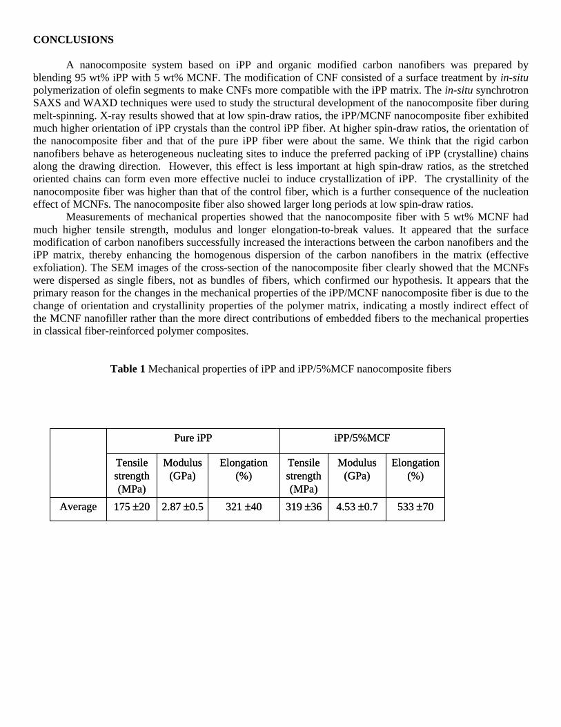
CONCLUSIONS A nanocomposite system based on iPP and organic modified carbon nanofibers was prepared by
blending 95 wt% iPP with 5 wt% MCNF. The modification of CNF consisted of a surface treatment by in-situ polymerization of olefin segments to make CNFs more compatible with the iPP matrix. The in-situ synchrotron SAXS and WAXD techniques were used to study the structural development of the nanocomposite fiber during melt-spinning. X-ray results showed that at low spin-draw ratios, the iPP/MCNF nanocomposite fiber exhibited much higher orientation of iPP crystals than the control iPP fiber. At higher spin-draw ratios, the orientation of the nanocomposite fiber and that of the pure iPP fiber were about the same. We think that the rigid carbon nanofibers behave as heterogeneous nucleating sites to induce the preferred packing of iPP (crystalline) chains along the drawing direction. However, this effect is less important at high spin-draw ratios, as the stretched oriented chains can form even more effective nuclei to induce crystallization of iPP. The crystallinity of the nanocomposite fiber was higher than that of the control fiber, which is a further consequence of the nucleation effect of MCNFs. The nanocomposite fiber also showed larger long periods at low spin-draw ratios.
Measurements of mechanical properties showed that the nanocomposite fiber with 5 wt% MCNF had much higher tensile strength, modulus and longer elongation-to-break values. It appeared that the surface modification of carbon nanofibers successfully increased the interactions between the carbon nanofibers and the iPP matrix, thereby enhancing the homogenous dispersion of the carbon nanofibers in the matrix (effective exfoliation). The SEM images of the cross-section of the nanocomposite fiber clearly showed that the MCNFs were dispersed as single fibers, not as bundles of fibers, which confirmed our hypothesis. It appears that the primary reason for the changes in the mechanical properties of the iPP/MCNF nanocomposite fiber is due to the change of orientation and crystallinity properties of the polymer matrix, indicating a mostly indirect effect of the MCNF nanofiller rather than the more direct contributions of embedded fibers to the mechanical properties in classical fiber-reinforced polymer composites.
Table 1 Mechanical properties of iPP and iPP/5%MCF nanocomposite fibers
2.87 ±0.5 4.53 ±0.7
Modulus (GPa)
Modulus (GPa)
533 ±70319 ±36321 ±40175 ±20Average
Elongation (%)
Tensile strength (MPa)
Elongation (%)
Tensile strength (MPa)
iPP/5%MCFPure iPP
2.87 ±0.5 4.53 ±0.7
Modulus (GPa)
Modulus (GPa)
533 ±70319 ±36321 ±40175 ±20Average
Elongation (%)
Tensile strength (MPa)
Elongation (%)
Tensile strength (MPa)
iPP/5%MCFPure iPP
REFERENCES
1. Chen, J.; Rao, A. M.; Lyuksyutov, Itkis, M. E.; Hamon, M. A.; Hu, H.; Cohn, R. W.; Eklund, P. C.;
Colbert, D. T.; Smalley, R. E. and Haddon, R. C., J. Phys. Chem. B, 2001, 105, 2525.
2. Thostenson, E.T.; Ren Z. and Chou, T.W., Composites Science and Technology, 2001, 61, 1899.
3. Baker, R.T.K. and Harris, P.S., in Chemistry and Physics of Carbon, edited by P.L. Walker, Jr. and P.A.
Thrower (Marcel Dekker, New York, 1978), Vol.14, p.83.
4. Oberlin, A.; Endo, M. and Koyama, T., J. Cryst. Growth, 1976, 32, 335.
5. Dresselhaus, M.S.; Dresselhaus, G.; Sugihara, K.; Spain, I.L. and Goldberg, H.A., Graphite Fibers and
Filaments, Springer Series in Materials Science 5 (Springer-Verlag, New York, 1988).
6. Rodriguez, N.M., J. Mater, Res., 1993, 8(12), 3233.
7. Kumar, S.; Doshi, H.; Srinivasarao, M.; Park, J.O.; Schiraldi, D.A., Polymer, 2002, 43, 1701.
8. Lozano, K. and Barrera E.V., J. Appl. Polym. Sci., 2001, 79, 125.
9. Carneiro, O.S. and Maia, J.M., Polym. Compos., 2000, 21, 961.
10. Pogue, R.T.; Ye, J.; Klosterman D.A.; Glass, A.S. and Chartoff, R.P., Composites (Part A), 1998, 29, 1273.
11. Hirsch, A., Angew. Chem. Int. Ed., 2002, 41(11), 1853.
12. Chen, J.; Rao, A.M.; Lyuksyutov, S.; Itkis, M.E.; Hamon, M.A.; Hu, H.; Cohn, R.W.; Eklund, P.C.;
Colbert, D.T.; Smalley, R.E. and Haddon, R.C., J. Phys. Chem. B, 2001, 105, 2525.
13. Chen, J.; Hamon, M.A.; Hu, H.; Chen, Y.; Rao, A.M.; Eklund, P.C.; Haddon, R.C., Science, 1998, 282, 95.
14. Hamon, M.A.; Chen, J.; Hu, H.; Chen, Y.; Itkis, M.E.; Rao, A.M.; Eklund, P.C.; Haddon, R.C., Adv.
Mater., 1999, 11, 834.
15. Holzinger, M.; Vostrowsky, O.; Hirsch, A.; Hennrich, F.; Kappes, M.; Weiss, R.; Jellen, F., Angew. Chem.,
2001, 113, 4132.
16. Curran, S.A.; Ajayan, P.M.; Blau, W.J.; Carroll, D.L.; Coleman, J.N.; Dalton, A.B.; Davey, A.P.; Drury,
A.; McCarthy, B.; Maier, S. and Strevens, A., Adv. Mater., 1998, 10, 1091.
17. Han, W.; Fan, S.; Li, Q. and Hu, Y., Science, 1997, 277, 1287.
18. Ran, S.; Burger, C.; Fang, D.; Zong, X.; Cruz, S.; Hsiao, B. S.; Chu, B.; Bubeck, R. A.; Yabuki, K.;
Teramoto, Y.; Martin, D. C.; Johnson M. A. and Cunniff, P. M., Macromolecules, 2002, 35, 433
19. Gravert, D. J.; Janda, K. D. Tetrahedron Lett. 1998, 39, 1513
20. Friend, S. O.; Barber, J. J. U.S. patent 1997, # 5611964
21. Benoit, D.; Harth, E.; Fox, P.; Waymouth, R. M.; Hawker, C. J. Macromolecules 2000, 33, 363
22. Hahn, S. F. J. Polym. Sci., Part A: Polym. Chem. 1992, 30, 397
23. Alexander, L.E., X-ray Diffraction in Polymer Science. New York: Wiley, 1969, (582 pp).
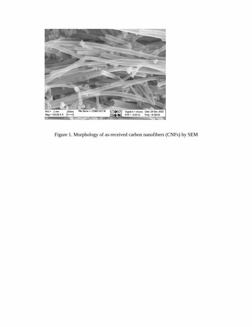
Figure 1. Morphology of as-received carbon nanofibers (CNFs) by SEM
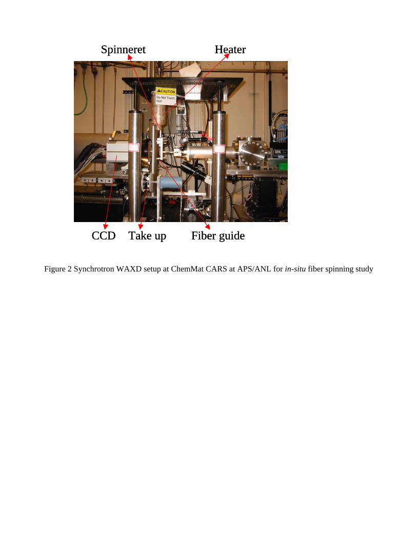
Figure 2 Synchrotron WAXD setup at ChemMat CARS at APS/ANL for in-situ fiber spinning study
HeaterSpinneret
Take up Fiber guideCCD
HeaterSpinneret
Take up Fiber guideCCD
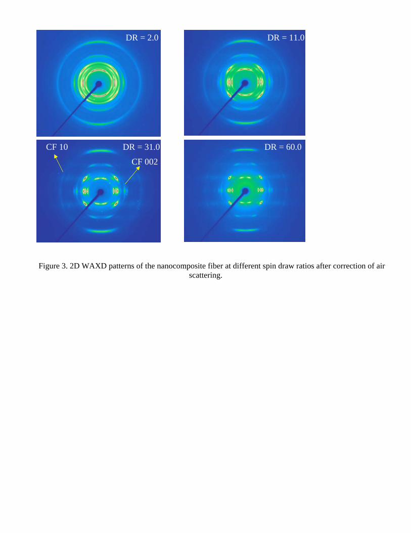
Figure 3. 2D WAXD patterns of the nanocomposite fiber at different spin draw ratios after correction of air scattering.
DR = 2.0 DR = 11.0
DR = 31.0 DR = 60.0DR = 60.0
CF 002
CF 10
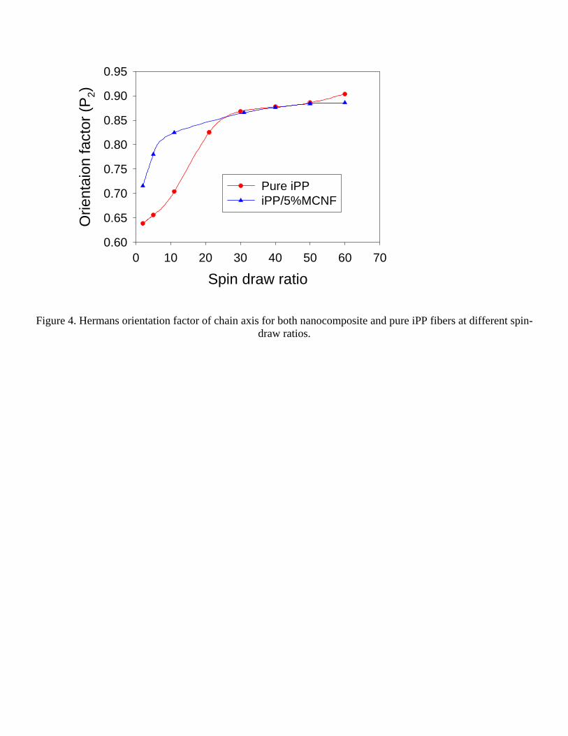
Figure 4. Hermans orientation factor of chain axis for both nanocomposite and pure iPP fibers at different spin-
draw ratios.
Spin draw ratio0 10 20 30 40 50 60 70
Orie
ntai
on fa
ctor
(P2)
0.60
0.65
0.70
0.75
0.80
0.85
0.90
0.95
Pure iPPiPP/5%MCNF
Spin Draw Ratio0.0 10.0 20.0 30.0 40.0 50.0 60.0 70.0
Cry
stal
linity
0.58
0.60
0.62
0.64
0.66
0.68
0.70
0.72
0.74
5% MCNF with iPPPure iPP
Figure 5 Crystallinity of the nanocomposite and pure iPP fibers as a function of spin-draw ratio
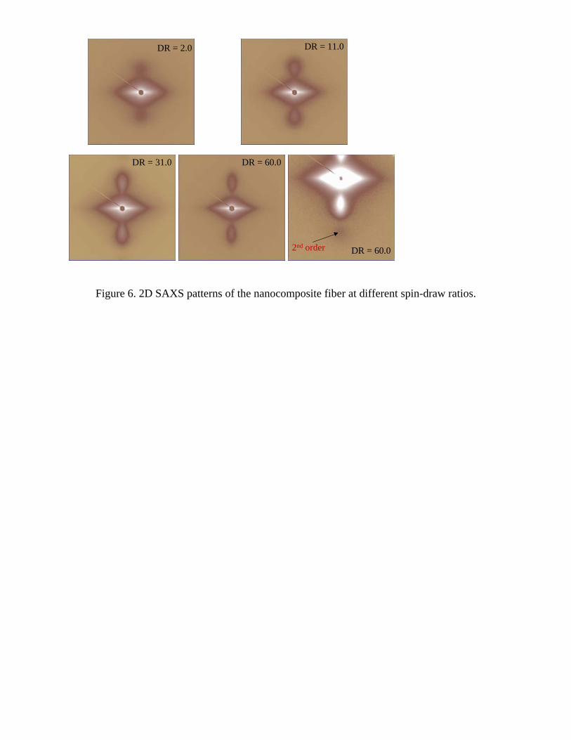
Figure 6. 2D SAXS patterns of the nanocomposite fiber at different spin-draw ratios.
DR = 2.0 DR = 11.0
DR = 31.0 DR = 60.0
DR = 60.02nd order
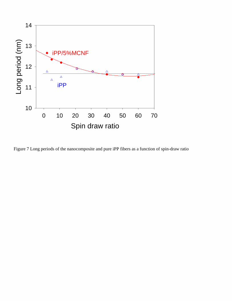
Figure 7 Long periods of the nanocomposite and pure iPP fibers as a function of spin-draw ratio
iPP/5%MCNF
Spin draw ratio0 10 20 30 40 50 60 70
Long
per
iod
(nm
)
10
11
12
13
14
iPP
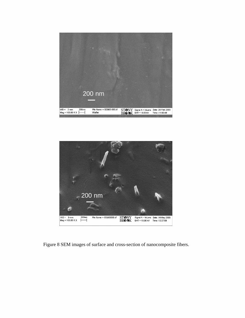
Figure 8 SEM images of surface and cross-section of nanocomposite fibers.
200 nm
200 nm


![[Benjamin Franklin] the Autobiography of Benjamin (Bookos-z1.Org)](https://img.pdfslide.us/doc/110x75/577cd4521a28ab9e789834de/benjamin-franklin-the-autobiography-of-benjamin-bookos-z1org.jpg)
