Embed Size (px)
Citation preview
Point level switch for liquidsin the food and beverage industry
Application
The Liquipoint FTW23 is a point level switch for water-based liquids.
It is used preferably in storage tanks, mixing vessels and pipes. Developed and builtfor the food and beverage industry, the Liquipoint FTW23 meets internationalhygienic requirements.
The Liquipoint FTW23 can be used permanently in process temperatures up to100 °C (212 °F) and in cleaning and sterilization processes to 135 °C (275 °F) for 60minutes.
Your benefits
• Individual adjustment to each medium not necessary• Easy installation thanks to compact design - even in tight conditions or where
access is restricted• Robust stainless steel housing, optionally available with M12x1 connector with
IP69K protection• Onsite function check via LED indication• Function test of the switch output with test magnet• Can be cleaned and sterilized in place (CIP/SIP)• 3-A and EHEDG certificates• Meets the requirements of EU 1935/2004, 10/2011, 2023/2006 and FDA 21
CFR 177.2415
Products Solutions Services
Technical InformationLiquipoint FTW23Capacitance point level measurement
TI01202F/00/EN/04.1671316230
Liquipoint FTW23
2 Endress+Hauser
Table of contents
Document information . . . . . . . . . . . . . . . . . . . . . . . 3Document conventions . . . . . . . . . . . . . . . . . . . . . . . . . . 3
Function and system design . . . . . . . . . . . . . . . . . . . 3Measuring principle . . . . . . . . . . . . . . . . . . . . . . . . . . . . 3Measuring system . . . . . . . . . . . . . . . . . . . . . . . . . . . . . 3
Input . . . . . . . . . . . . . . . . . . . . . . . . . . . . . . . . . . . . . 4Measured variable . . . . . . . . . . . . . . . . . . . . . . . . . . . . . 4Measuring range . . . . . . . . . . . . . . . . . . . . . . . . . . . . . . 4
Output . . . . . . . . . . . . . . . . . . . . . . . . . . . . . . . . . . . 4Switch output . . . . . . . . . . . . . . . . . . . . . . . . . . . . . . . . 4
Power supply . . . . . . . . . . . . . . . . . . . . . . . . . . . . . . 4Supply voltage . . . . . . . . . . . . . . . . . . . . . . . . . . . . . . . 4Power consumption . . . . . . . . . . . . . . . . . . . . . . . . . . . . 4Current consumption . . . . . . . . . . . . . . . . . . . . . . . . . . . 4Electrical connection . . . . . . . . . . . . . . . . . . . . . . . . . . . 5Cable specification . . . . . . . . . . . . . . . . . . . . . . . . . . . . . 5Connecting cable length . . . . . . . . . . . . . . . . . . . . . . . . . 5Overvoltage protection . . . . . . . . . . . . . . . . . . . . . . . . . . 5
Performance characteristics . . . . . . . . . . . . . . . . . . . 6Reference operating conditions . . . . . . . . . . . . . . . . . . . . 6Switching accuracy . . . . . . . . . . . . . . . . . . . . . . . . . . . . 6Hysteresis . . . . . . . . . . . . . . . . . . . . . . . . . . . . . . . . . . 6Non-repeatability . . . . . . . . . . . . . . . . . . . . . . . . . . . . . 6Switching delay . . . . . . . . . . . . . . . . . . . . . . . . . . . . . . . 6Switch-on delay . . . . . . . . . . . . . . . . . . . . . . . . . . . . . . 6
Installation . . . . . . . . . . . . . . . . . . . . . . . . . . . . . . . . 6Orientation . . . . . . . . . . . . . . . . . . . . . . . . . . . . . . . . . 6
Environment . . . . . . . . . . . . . . . . . . . . . . . . . . . . . . . 7Ambient temperature range . . . . . . . . . . . . . . . . . . . . . . 7Storage temperature . . . . . . . . . . . . . . . . . . . . . . . . . . . 7Climate class . . . . . . . . . . . . . . . . . . . . . . . . . . . . . . . . 7Altitude . . . . . . . . . . . . . . . . . . . . . . . . . . . . . . . . . . . . 7Degree of protection . . . . . . . . . . . . . . . . . . . . . . . . . . . 7Shock resistance . . . . . . . . . . . . . . . . . . . . . . . . . . . . . . 7Vibration resistance . . . . . . . . . . . . . . . . . . . . . . . . . . . . 7Cleaning . . . . . . . . . . . . . . . . . . . . . . . . . . . . . . . . . . . 7Electromagnetic compatibility . . . . . . . . . . . . . . . . . . . . . 7Reverse polarity protection . . . . . . . . . . . . . . . . . . . . . . . 7Short-circuit protection . . . . . . . . . . . . . . . . . . . . . . . . . 7
Process . . . . . . . . . . . . . . . . . . . . . . . . . . . . . . . . . . . 8Process temperature range . . . . . . . . . . . . . . . . . . . . . . . 8Process pressure range . . . . . . . . . . . . . . . . . . . . . . . . . . 8Process fluid . . . . . . . . . . . . . . . . . . . . . . . . . . . . . . . . . 8
Mechanical construction . . . . . . . . . . . . . . . . . . . . . . 8Weight . . . . . . . . . . . . . . . . . . . . . . . . . . . . . . . . . . . . 8Materials . . . . . . . . . . . . . . . . . . . . . . . . . . . . . . . . . . . 9
Operability . . . . . . . . . . . . . . . . . . . . . . . . . . . . . . . . 9Light signals (LED) . . . . . . . . . . . . . . . . . . . . . . . . . . . . 9Function test . . . . . . . . . . . . . . . . . . . . . . . . . . . . . . . . 9
Certificates and approvals . . . . . . . . . . . . . . . . . . . 10CE mark . . . . . . . . . . . . . . . . . . . . . . . . . . . . . . . . . . . 10RCM-Tick mark . . . . . . . . . . . . . . . . . . . . . . . . . . . . . . 10Approval . . . . . . . . . . . . . . . . . . . . . . . . . . . . . . . . . . 10Sanitary compatibility . . . . . . . . . . . . . . . . . . . . . . . . . 10Hygienic approvals . . . . . . . . . . . . . . . . . . . . . . . . . . . 11Manufacturer's Declaration . . . . . . . . . . . . . . . . . . . . . . 11
Ordering information . . . . . . . . . . . . . . . . . . . . . . . 11
Accessories . . . . . . . . . . . . . . . . . . . . . . . . . . . . . . . 11Process adapter M24 . . . . . . . . . . . . . . . . . . . . . . . . . . 11Weld-in adapter . . . . . . . . . . . . . . . . . . . . . . . . . . . . . 11Slotted nut DIN11851 . . . . . . . . . . . . . . . . . . . . . . . . . 11Additional accessories . . . . . . . . . . . . . . . . . . . . . . . . . 12
Supplementary documentation . . . . . . . . . . . . . . . 12Operating Instructions . . . . . . . . . . . . . . . . . . . . . . . . . 12Supplementary documentation . . . . . . . . . . . . . . . . . . . 12

Liquipoint FTW23
Endress+Hauser 3
Document information
Document conventions Symbols for certain types of information
Symbol Meaning
PermittedIndicates procedures, processes or actions that are allowed.
PreferredIndicates procedures, processes or actions that are preferred.
TipIndicates additional information.
Reference to pageRefers to the corresponding page number.
Symbols in graphics
Symbol Meaning
1, 2, 3 ... Item numbers
A, B, C, ... Views
Function and system design
Measuring principle The capacitance at the tip of the sensor, and therefore the dielectric value of the medium, isdetermined using an electrical field. Given that the dielectric value of air and a water-based liquiddiffer, the Liquipoint FTW23 can differentiate between the two states, i.e. covered and uncovered.
Measuring system The measuring system consists of a Liquipoint FTW23 point level switch, e.g. for connection toprogrammable logic controllers (PLC).
1
2
3
A0016844
1 Application examples
1 Overfill protection or upper level detection (MAX)2 Pump dry running protection (MIN)3 Lower level detection (MIN)
Liquipoint FTW23
4 Endress+Hauser
Input
Measured variable The change in medium capacitance is detected by the electrode in contact with the process.
Measuring range Water-based media
E.g.: mineral water, milk and various dairy products, softdrinks, beer as well as media with adielectric constant > 20
Not suitable for oil-based media or media that form heavy buildup. The Liquipoint FTW33 isrecommended for these applications.
Output
Switch output • Function: 3-wire DC-PNPPositive voltage signal at the switch output of the electronics
• Switching behavior: ON/OFF• Connectable load: 200 mA (short-circuit proof)• Safety-related switching: MIN or MAX point level
The electrical switch opens if the point level is reached or if faults or a power outage occur.– Maximum point level detection (MAX): e.g. for overfill protection
The device keeps the electrical switch closed as long as the sensor is not yet covered by liquid.– Minimum point level detection (MIN): e.g. for dry running protection in pumps
The device keeps the electrical switch closed as long as the sensor is covered by liquid.• Residual voltage: < 3 V• Residual current: < 100 µA
Power supply
Supply voltage 10 to 30 V DC
Power consumption < 1.2 W (at max. load: 200 mA)
Current consumption < 40 mA

Liquipoint FTW23
Endress+Hauser 5
Electrical connection Voltage source: non-hazardous contact voltage or Class 2 circuit (North America). The device mustbe operated with a fine-wire fuse 500 mA (slow-blow).
Depending on the analysis of the switch outputs, the device works in the MAX (maximum point leveldetection) or MIN (minimum point level detection) mode.
Electrical connection Mode of operation
M12 connector MAX MIN
0.5A
L– L+
2 1
3 4
K 0.5A
L– L+
2 1
3 4
K
1
21
2
1
41
4
Symbols
K
DescriptionYellow LED (ye) litYellow LED (ye) not litexternal load
Function monitoring
With two-channel evaluation, functional monitoring of the sensor is also possible in addition to levelmonitoring.
When both outputs are connected, the MIN and MAX outputs assume opposite states when thedevice is operating fault-free (XOR). In the event of an alarm condition or a line break, both outputsare de-energized.
Connection for function monitoring with antivalence Yellow LED(ye)
Red LED(rd)
0.5A
L– L+
2 1
3 4
K1 K2
Sensor covered1
21
4
Sensor uncovered41
1 2
Fault21
41
Symbols
K1 / K2
DescriptionLED litLED not litFault or warningexternal load
Cable specification IEC 60947-5-2
Connecting cable length Max. 25 Ω/core, total capacity < 100 nF
Overvoltage protection Overvoltage category II
Liquipoint FTW23
6 Endress+Hauser
Performance characteristics
Reference operatingconditions
Horizontal orientation:• Ambient temperature: 20 °C (68 °F) ±5 °C• Medium temperature: 20 °C (68 °F) ±5 °C• Process pressure: 1 bar (14.5 psi)• Medium: water
Switching accuracy ±2 mm (0.08 in) in accordance with DIN 61298-2
Hysteresis Typically ±1 mm (0.04 in)
Non-repeatability ±1 mm (0.04 in) in accordance with DIN 61298-2
Switching delay • 0.5 s when sensor is covered• 1.0 s when sensor is uncovered
Switch-on delay < 2 s (previously not through-connected)
Installation
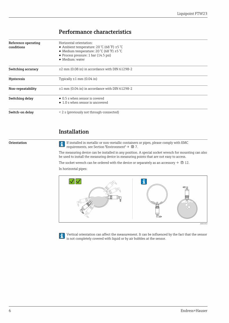
Orientation If installed in metallic or non-metallic containers or pipes, please comply with EMCrequirements, see Section "Environment" → 7.
The measuring device can be installed in any position. A special socket wrench for mounting can alsobe used to install the measuring device in measuring points that are not easy to access.
The socket wrench can be ordered with the device or separately as an accessory → 12.
In horizontal pipes:
G 3
/4
316L
G 3
/4
316L
G 3
/4 316L G 3/4316L
A0021052
Vertical orientation can affect the measurement. It can be influenced by the fact that the sensoris not completely covered with liquid or by air bubbles at the sensor.

Liquipoint FTW23
Endress+Hauser 7
Environment
Ambient temperature range –20 to +70 °C (–4 to +158 °F), see following derating diagram:
I <50 mAmax
0 +50 +80 +135
–20
+32 +122 +176 +275
–4
–20
+70
[°C]
–4
[°F]
0+32
[°C]
[°F]
TP
Ta
+35+95
+150
+302
I <50 mAmax
+158
A0026131
Ta Ambient temperatureTp Process temperature
Storage temperature –40 to +85 °C (–40 to +185 °F)
Climate class DIN EN 60068-2-38/IEC 68-2-38: test Z/AD
Altitude Up to 2 000 m (6 600 ft) above sea level
Degree of protection • IP65/67 NEMA Type 4X Enclosure (M12 connector for plastic housing cover)• IP66/68/69K 1) NEMA Type 4X/6P Enclosure (M12 connector for metal housing cover)
Shock resistance In accordance with EA inspection, prEN 60068-2-27:2007: a = 300 m/s 2 = 30 g, 3 planes x 2directions x 3 shocks x 18 ms
Vibration resistance In accordance with test Fh, EN 60068-2-64:2008: a(RMS) = 50 m/s2, f = 5 to 2000 Hz, t = 3 planesx 2 h
Cleaning Resistant to typical cleaning agents from the outside. Passed Ecolab test.
Electromagneticcompatibility
The electromagnetic compatibility requirements outlined in the EN 61326 series for industrialenvironments are met when the device is installed in metal vessels or pipes. Emission requirementsfor class B equipment are met. For details refer to the declaration of conformity.
If the device is installed in plastic structures, its function may be influenced by strongelectromagnetic fields. Emission requirements for class A equipment are met (only for use in"industrial environments").
Reverse polarity protection Integrated; no damage in the event of reverse polarity or short-circuit
Short-circuit protection Overload protection/short-circuit protection at I > 200 mA; the sensor is not destroyed.
Intelligent monitoring: Testing for overload at intervals of approx. 1.5 s; normal operation resumesonce the overload/short-circuit has been rectified
1) The IP69K protection class is defined in accordance with DIN 40050 Part 9. This standard was withdrawn on 01.11.2012 and replaced by DIN EN60529. The name of the IP protection class changed to IP69 as part of this.
Liquipoint FTW23
8 Endress+Hauser
Process
Process temperature range –20 to +100 °C (–4 to +212 °F)
For 1 hour:+135 °C (+275 °F)
Process pressure range –1 to +16 bar (–14.5 to +232 psi)
Process fluid Water-based medium (dielectric constant >20)
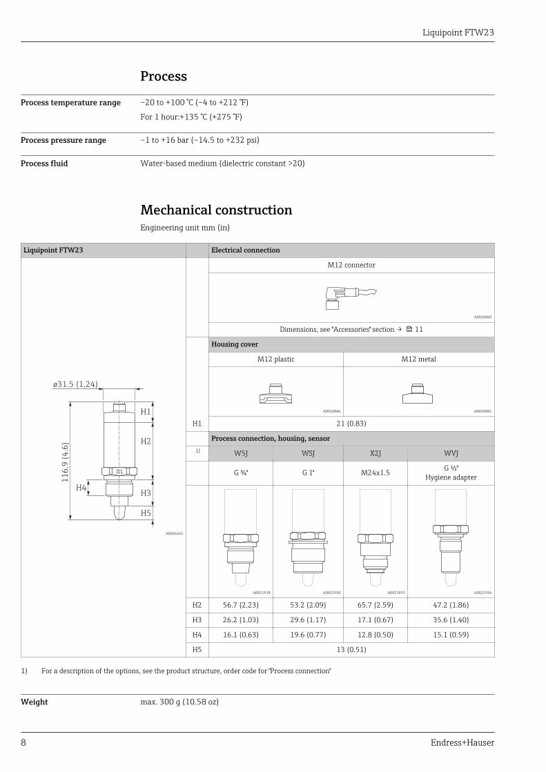
Mechanical constructionEngineering unit mm (in)
Liquipoint FTW23 Electrical connection
316L
G 3/4
H5
H2
H3
H1
11
6.9
(4
.6)
ø31.5 (1.24)
H4
A0026265
M12 connector
A0016840
Dimensions, see "Accessories" section → 11
H1
Housing cover
M12 plastic M12 metal
A0016846 A0016845
21 (0.83)
Process connection, housing, sensor 1) W5J WSJ X2J WVJ
G ¾" G 1" M24x1.5 G ½"Hygiene adapter
A0021918 A0021920 A0021953 A0021916
H2 56.7 (2.23) 53.2 (2.09) 65.7 (2.59) 47.2 (1.86)
H3 26.2 (1.03) 29.6 (1.17) 17.1 (0.67) 35.6 (1.40)
H4 16.1 (0.63) 19.6 (0.77) 12.8 (0.50) 15.1 (0.59)
H5 13 (0.51)
1) For a description of the options, see the product structure, order code for "Process connection"
Weight max. 300 g (10.58 oz)
Liquipoint FTW23
Endress+Hauser 9
Materials Material specifications in accordance with AISI and DIN EN.
Materials in contact with process Materials not in contact with process
Sensor: 316L (1.4404), PEEKThe material PEEK meets the requirements of EU1935/2004, 10/2011, 2023/2006 and FDA 21 CFR177.2415
Housing covers:• M12 metal: 316L (1.4404)• M12 plastic: PPSU
Design ring: PBT/PC
Process connection: 316L (1.4404/1.4435)Housing: 316L (1.4404/1.4435)
Nameplate: lasered onto housing
Wetted sensor surface: Ra ≤ 0.76 µm (30 µin)
Endress+Hauser supplies DIN/EN process connections with threaded connection in stainlesssteel in accordance with AISI 316L (DIN/EN material number 1.4404 or 14435). In terms oftheir stability-temperature property, the materials 1.4404 and 1.4435 are grouped in EN1092-1 table 18 under 13E0. The chemical composition of the two materials can be identical.
Operability
Light signals (LED)
1
2 3
4
2
31
A0022024
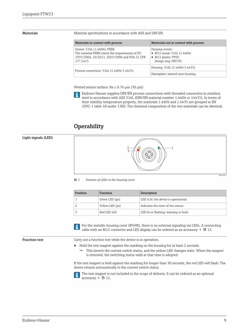
2 Position of LEDs in the housing cover
Position Function Description
1 Green LED (gn) LED is lit: the device is operational
2 Yellow LED (ye) Indicates the state of the sensor
3 Red LED (rd) LED lit or flashing: warning or fault
For the metallic housing cover (IP69K), there is no external signaling via LEDs. A connectingcable with an M12 connector and LED display can be ordered as an accessory → 12.
Function test Carry out a function test while the device is in operation.
‣ Hold the test magnet against the marking on the housing for at least 2 seconds. This inverts the current switch status, and the yellow LED changes state. When the magnet
is removed, the switching status valid at that time is adopted.
If the test magnet is held against the marking for longer than 30 seconds, the red LED will flash: Thedevice returns automatically to the current switch status.
The test magnet is not included in the scope of delivery. It can be ordered as an optionalaccessory → 12.

Liquipoint FTW23
10 Endress+Hauser
TESTN
Se
r. n
o.:
Ord
er
co
de
:
Ext.
ord
. cd
.:
A0024417
3 Position for test magnet on housing
Certificates and approvals
CE mark The measuring system is in conformity with the statutory requirements of the applicable ECDirectives. These are listed in the corresponding EC Declaration of Conformity along with thestandards applied. Endress+Hauser confirms successful testing of the device by affixing to it the CEmark.
RCM-Tick mark The measuring system complies with EMC requirements of the "Australian Communications andMedia Authority (ACMA)".
Approval CSA C/US General Purpose
Sanitary compatibility The device has been developed for use in hygienic processes. The wetted materials meet therequirements of EU 1935/2004, 10/2011, 2023/2006 and FDA 21 CFR 177.2415 as well as the 3-A Sanitary Standard No. 74-xx. Endress+Hauser confirms this by affixing the 3-A symbol to thedevice.
The following certificate copies can be ordered with the device (optional):
3-A
74-xx
EHEDG
TYPE EL - CLASS Ixxx
• If cleaning in place (CIP) is required, weld-in adapters that comply with 3-A requirements areoffered. If installed horizontally, ensure that the leakage hole is pointing downwards. This allowsleaks to be detected as quickly as possible.
• To avoid the risk of contamination, install the device in accordance with the design principles ofEHEDG, Document 37 "Hygienic Design and Application for Sensors" and Document 16 "HygienicPipe Connections".
• Suitable connections and seals must be used in order to guarantee a hygienic design in accordancewith the specifications of 3-A and EHEDG.
• Information on 3-A and EHEDG-approved weld-in adapters can be found in the "Weld-in adapter,process adapter and flanges" documentation, TI00426F/00/EN.
• The gap-free connections can be cleaned of all residue using sterilization in place (SIP) andcleaning in place (CIP), which are typical cleaning methods within the industry. Attention must bepaid to the pressure and temperature specifications of the sensor and process connections for CIPand SIP processes.
Liquipoint FTW23
Endress+Hauser 11
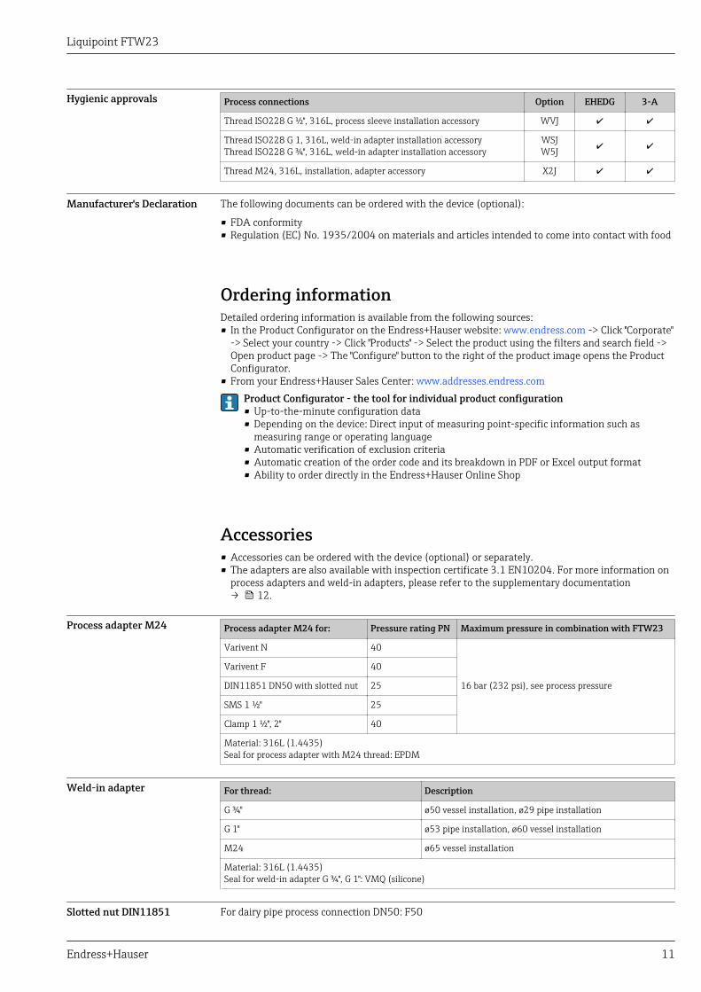
Hygienic approvals Process connections Option EHEDG 3-A
Thread ISO228 G ½", 316L, process sleeve installation accessory WVJ
Thread ISO228 G 1, 316L, weld-in adapter installation accessoryThread ISO228 G ¾", 316L, weld-in adapter installation accessory
WSJW5J
Thread M24, 316L, installation, adapter accessory X2J
Manufacturer's Declaration The following documents can be ordered with the device (optional):
• FDA conformity• Regulation (EC) No. 1935/2004 on materials and articles intended to come into contact with food
Ordering informationDetailed ordering information is available from the following sources:• In the Product Configurator on the Endress+Hauser website: www.endress.com -> Click "Corporate"
-> Select your country -> Click "Products" -> Select the product using the filters and search field ->Open product page -> The "Configure" button to the right of the product image opens the ProductConfigurator.
• From your Endress+Hauser Sales Center: www.addresses.endress.comProduct Configurator - the tool for individual product configuration• Up-to-the-minute configuration data• Depending on the device: Direct input of measuring point-specific information such as
measuring range or operating language• Automatic verification of exclusion criteria• Automatic creation of the order code and its breakdown in PDF or Excel output format• Ability to order directly in the Endress+Hauser Online Shop
Accessories• Accessories can be ordered with the device (optional) or separately.• The adapters are also available with inspection certificate 3.1 EN10204. For more information on
process adapters and weld-in adapters, please refer to the supplementary documentation→ 12.
Process adapter M24 Process adapter M24 for: Pressure rating PN Maximum pressure in combination with FTW23
Varivent N 40
16 bar (232 psi), see process pressure
Varivent F 40
DIN11851 DN50 with slotted nut 25
SMS 1 ½" 25
Clamp 1 ½", 2" 40
Material: 316L (1.4435)Seal for process adapter with M24 thread: EPDM
Weld-in adapter For thread: Description
G ¾" ø50 vessel installation, ø29 pipe installation
G 1" ø53 pipe installation, ø60 vessel installation
M24 ø65 vessel installation
Material: 316L (1.4435)Seal for weld-in adapter G ¾", G 1": VMQ (silicone)
Slotted nut DIN11851 For dairy pipe process connection DN50: F50
Liquipoint FTW23
12 Endress+Hauser
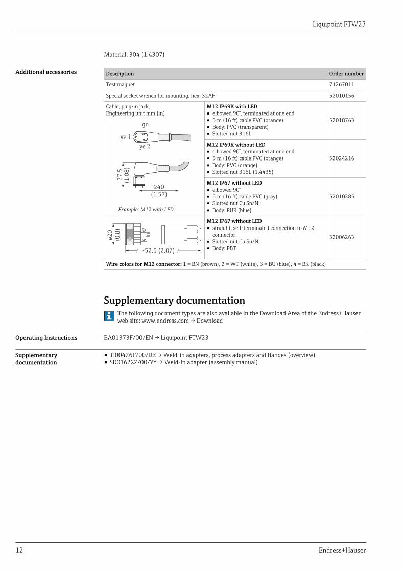
Material: 304 (1.4307)
Additional accessories Description Order number
Test magnet 71267011
Special socket wrench for mounting, hex, 32AF 52010156
Cable, plug-in jack,Engineering unit mm (in)
M12 IP69K with LED• elbowed 90°, terminated at one end• 5 m (16 ft) cable PVC (orange)• Body: PVC (transparent)• Slotted nut 316L
52018763
ye 1
ye 2
gn2
7.5
(1.0
8)
40
(1.57)
³
Example: M12 with LED
M12 IP69K without LED• elbowed 90°, terminated at one end• 5 m (16 ft) cable PVC (orange)• Body: PVC (orange)• Slotted nut 316L (1.4435)
52024216
M12 IP67 without LED• elbowed 90°• 5 m (16 ft) cable PVC (gray)• Slotted nut Cu Sn/Ni• Body: PUR (blue)
52010285
~52.5 (2.07)
ø2
0
(0.8
)
M12 IP67 without LED• straight, self-terminated connection to M12
connector• Slotted nut Cu Sn/Ni• Body: PBT
52006263
Wire colors for M12 connector: 1 = BN (brown), 2 = WT (white), 3 = BU (blue), 4 = BK (black)
Supplementary documentationThe following document types are also available in the Download Area of the Endress+Hauserweb site: www.endress.com → Download
Operating Instructions BA01373F/00/EN → Liquipoint FTW23
Supplementarydocumentation
• TI00426F/00/DE → Weld-in adapters, process adapters and flanges (overview)• SD01622Z/00/YY → Weld-in adapter (assembly manual)


www.addresses.endress.com
*71316230*71316230


![Nivotester FTL325P-#3#3 - portal.endress.com · CH1 CH2 C H3 325 [Ex ia] CH2 C H3 C H1 KA00168F/00/A6/13.15 71296989 Products Solutions Service Operating Instructions Nivotester FTL325P-#3#3](https://img.pdfslide.us/doc/110x75/5aef6c6c7f8b9a572b8e12b9/nivotester-ftl325p-33-ch2-c-h3-325-ex-ia-ch2-c-h3-c-h1-ka00168f00a61315.jpg)