Embed Size (px)
Citation preview

NASA
SPACEVEHICLEDESIGNCRITERIA
(CHEMICALPROPULSION)
NASASP.8087
COPY
LIQUID ROCKET ENGINEFLUID-COOLED
COMBUSTION CHAMBERS
APRIL1972
NATIONAL AERONAUTICS AND SPACE ADMINISTRATION
https://ntrs.nasa.gov/search.jsp?R=19730022965 2018-05-12T22:58:38+00:00Z


FOREWORD
NA%A expcYic ice has indicated a need f_r uniform criteria for tile design of space vehicles.
Acct)ldingly. criteria aft being dcvelopcd il_ the following areas of technology'
l:_lY¢iro n i110 FIt
Struclurcs
(_uidancc and Control
Chemical ])ropulsion
ltldividual comp(met_s of this work will be issued as separate monographs as soon as they
arc complcled. This document, part of lhc series on Chemical Propulsion, is olle such
monogJaph. A list of all monographs isstlcd Io date can be found on the final pages of this
d_),., fillip_' I 1.
These monographs are to bc Jcgarded as guides to design and not as NASA requirements,
except as illay be specified in formal project specifications. It is expected, however, that
these doculncnts, revised as experience may indicate to be desirable, eventually will provide
unifornl design practices for NASA space vehicles.
This m(mograph, "liquid Rocket Elagine Fluid-Cooled Combustion Chambers," was
prepared tinder the dilcction of tloward W. Douglass, Chief, Design Criteria Office, Lewis
P,csea_ch (?enter: project management was by ttarold W. Schmidt. The monograph was
written by I)t. N. E. Van Huff and David A. Fairchild of the Aerojet Liquid Rocket
(_o,llpany, and was edited by Russell B. Keller, Jr., of l_ewis. To assure technical accuracy of
this document, scientists aild engineers throughoul the technical community participated in
interviews, constdtations, alld clitical review of lhe text. In particular, Dr. C. D. Coulbert of
the Jet Propulsion [_aboratory, California Institute of Technology; John Campbell of the
Rocketdyne Division, North American Rockwell Corporation: A. R. Eberle of the Spacel)ivision, North American Rockwell Corporation; rl'- F. Reinhardt of Bell Aerospace
Company: and W. (;. Anderson of the Lewis Research (?enter collectively and individually
reviewed the monograph in detail.
Comments concerning the technical content ot" this monograph will be welcomed by the
National Aerotlautics and Space Administration, Lewis Research Center (Design Criteria
Office), (Tlevcland, Ohio 44135.
April 1972

For sale by the National Technical Information Service
Springfield, Virginia 22151
Price $3.00
GUIDE TO THE USE OF THIS MONOGRAPH
The purpose of this monograph is to organize and present, for effective use in design, the
significant experience and knowledge accunlulated in development and operational
programs to date. It reviews and assesses current design practices, and from them establishes
firm guidance for achieving greater consistency in design, increased reliability in the end
product, and greater efficiency in the design effort. The monograph is organized into twomajor sections that are preceded by a brief introduction and complemented by a set ofreferences.
The State of the Art, section 2, reviews and discusses the total design problem, and
identifies which design elements are involved in successful design. It describes succinctly theestablished technology relevant to these elements.When detailed information is required, the
best available references are cited. This section serves as a survey of the subject that provides
background material and prepares a proper technological base for the Design Criteria andRecommended Practices.
The Design Criteria, shown in italics in section 3, state clearly and briefly what rule, guide,
limitation, or standard must be imposed on each essential design element to assure
successful design. The Design Criteria can serve effectively as a checklist of rules for the
project manager to use in guiding a design or in assessing its adequacy.
The Recommended Practices, also in section 3, state how to satisfy each of the criteria.
Whenever possible, the best procedure is described; wl_en this cannot be done concisely,appropriate references are provided. The Recommended Practices, in conjunction with the
Design Criteria, provide positive guidance to the practicing designer on how to achieve
successful design.
Both sections have been organized into decimally numbered subsections so that the subjects
within similarly numbered subsections correspond from section to section. The format for
the Contents displays this continuity of subject in such a way that a particular aspect of
design can be followed through both sections as a discrete subject.
The design criteria monograph is not intended to be a design handbook, a set of
specifications, or a design manual. It is a summary and a systematic ordering of the large and
loosely organized body of existing successful design techniques and practices. Its value and
its merit should be judged on how effectively it makes that material available to and useful
to the designer.
111

CONTENTS
I.
2.
3.
INTRODUCTION ............................
STATE OF THE ART ..........................
DESIGN CRITERIA and Recommended Practices ................
REFERENCES ................................
GLOSSARY .................................
NASA Space Vehicle Design Criteria Monographs Issued to Date .............
Page
1
4
54
95
101
107
SUBJECT STATE OF THE ART
REGENERATIVE COOLING 2.1 7
Coolant Passages 2.1.1 8
Basic Requirements 2.1.1.1 8
Number of Passes 2.1.1.2 10
Tubes 2.1.1.3 10
Geometry - -Wall Thickness
Bifurcation Joints - -
Tolerances - -
Channel Walls 2.1.1.4 14
Passage Shape - -Double-Wall Construction - -Interchannel Areas - -
Special Thermal and HydraulicConsiderations 2.1.1.5 15
Gas-Side Heating
Thermal Margins of Safety
Coolant Velocity - -
Wall Temperatures - -
DESIGN CRITERIA
3.1 54
3.1.1 54
3.1.1.1 54
3.1.1.2 54
3.1.1.3 55
3.1.1.3.1 553.1.1.3.2 56
3.1.1.3.3 56
3.1.1.3.4 58
3.1.1.4 58
3.1.1.4.1 58
3.1.1.4.2 593.1.1.4.3 59
3.1.1.5 59
3.1.1.5.1 59
3.1.1.5.2 61
3.1.1.5.3 62
3.1.1.5.4 62

SUBJECT STATE OF THE ART DESIGN CRITERIA
Manifolds
Flow Distribution
Structure
Chamber Reinforcement
Throat Reinforcement
Form-fitting shell
Integral Support Structure
Cylindrical Shell SupportStructure
Mechanically Attached Shell
Hoop Reinforcement
Nozzle Reinforcement
Interface Flange
Structural Effects
Thermal Effects
Materials
Compatibility
Physical Properties
Structural Analysis
General Requirements
Model AdequacyFailure Prediction
Crippling and Bursting Failure
Failure in Any Mode
Design Analysis
Buckling StrengthComposite Load Resistance
Tube Compressive Strength
Tube Fatigue Strength
2.1.2 19
2.1.2.1 19
2.1.2.2 20
2.1.3 21
2.1.3.1 22
2.1.3.2 26
2.1.3.3 27
2.1.4 27
2.1.5 30
2.1.6 32
2.1.6.1 33
2.1.6.2 33
3.1.2 62
3.1.2.1 62
3.1.2.2 63
3.1.3 65
3.1.3.1 65
3.1.3.1.1 65
3.1.3.1.2 66
3.1.3.1.3 663.1.3.1.4 66
3.1.3.2 67
3.1.3.3 67
3.1.4 68
3.1.4.1 68
3.1.4.2 68
3.1.5 68
3.1.5.1 68
3.1.5.2 69
3.1.6 70
3.1.6.1 70
3.1.6.1.1 70
3.1.6.1.2 7O
3.1.6.1.3 71
3.1.6.1.4 71
3.1.6.2 75
3.1.6.2.1 75
3.1.6.2.2 75
3.1.6.2.3 75
3.1.6.2.4 75
vi

SUBJECT STATE OF THE ART DESIGN CRITERIA
Brazing
Braze ALloys
Prebraze Joint PreparationCleanliness
Joint Gap SizeMotion Restraint
Braze Procedure
Alloy Placement
Braze Retort Configuration
Retort/Chamber Mounting
Braze Joint TemperatureBraze Cycle
Cycle Repeatability
Chamber Assembly
Passage Degradation
Chamber Degradation
Chamber Dents
Laboratory Proof Testing
Test Objectives
Leak Detection
Flow Calibration
Operational Problems
Transient Operation
Postfire Heatsoak
Water-Vapor Trap
Drain Ports
Instrumentation
Handling and Transportation Damage
2.1.7 35 3.1.7 76
2.1.7.1 35 3.1.7.1 76
2.1.7.2 36 3.1.7.2 77
- 3.1.7.2.1 77
3.1.7.2.2 77
-- - 3.1.7.2.3 78
2.1.7.3 37 3.1.7.3 78
- - 3.1.7.3.1 78
- 3.1.7.3.2 79
- 3.1.7.3.3 79
- 3.1.7.3.4 80- - 3.1.7.3.5 80
- - 3.1.7.3.6 81
2.1.8 38 3.1.8 81
- - 3.1.8.1 81
- 3.1.8.2 81
- 3.1.8.3 82
2.1.9 41 3.1.9 82
- - 3.1.9.1 82
- 3.1.9.2 82
- - 3.1.9.3 83
2.1.10 41 3.1.10 83
- - 3.1.10.1 83
- - 3.1.10.2 84
- - 3.1.10.3 84
- - 3.1.10.4 84
- 3.1.10.5 84
- - 3.1.10.6 85
vii

SUBJECT STATE OF Till; ART DESIGN ('RI fklC, lA
TRANSPIRATION COOLING
Mechanical Design
Chamber Contour
Wall Material
Flow Quantity
Pressure Drop
Heat Load Variation
Flow-Control Simplicity
Flow-Control Thermal Protection
Flow-Control Characteristics
Flow-Circuit Structure
Hot-Spot Instability
Nozzle-Extension Losses
Fabrication
Prevention of Plugging
Wall Bending Limits
Localized Overheating
Surface Roughness
Operation
Start Sequence
Component Growth
Wall Repair
Injector Characteristics
Throttled Operation
2.2 43 _¢.2 g5
3.2.1 85
3.2.1.1 85
3.2.1.2 86
3.2.1.3 86
3.2.1.4 80
3.2.1.5 8a
3.2.1.6 87
3.2.1.7 87
3.2.1.(S' 87
3.2.1.9 8E
3.2.1.10 S8
3.2.1.11 88
3.2.2 88
3.2.2.1 88
3.2.2.2 8_
Z2.2.3 89
3.2.2.4 89
3.2.3 90
,¢.2.3. 1 90
3.2.3.2 O0
3.2.3.3 O0
3.2.3.4 9 t
3.2.3.5 Ol
viii
SUBJ I{CT STATE OF TI IE ART DESIGN CRITERIA
FIlM COOLING
('OATINGS
Spalling Without Failure
Coating Strength
2.3 49
2.4 51
3.3 91
3.4 93
3.4.1 93
3.4.2 93
iX

Figure
1
2
3
4
5
6
7
LIST OF FIGURES
Title Page
Coolant tube configurations ........................ 12
Methods of reinforcing nozzle throat zones .................. 23
Critical stress point in jacketed-chamber construction .............. 25
Injector mounting flange designs ...................... 29
Gap growth at support band with alternating tack welds ............. 39
Bifurcation joint construction ....................... 57
Heat transfer correlation factor Cg as a function of local area ratioand contraction ratio ........................... 60
Interface flange construction ........................ 64
xi


LIST OF TABLES
Table
1
II
llI
IV
V
VI
VIIA
VIIB
VIII
IX
X
XI
Title Page
Chief Features of Major Production Regeneratively Cooled Thrust Chambers .... 5
Qualitative Comparison of Methods of Coolant-Passage Construction ....... 9
Tube Materials and Propellant/Coolants Used in Tubular CombustionChambers .............................. 11
Propellants as Coolants ......................... 17
Chamber Structural Considerations .................... 34
Chief Features of Successful Transpiration-Cooled Thrust Chambers ....... 44
Evaluation of Random-Pore Walls .................... 46
Evaluation of Discrete-Pore Walls ..................... 47
Major Regeneratively Cooled Chambers with Supplemental Film Cooling ...... 50
Coated Thrust Chambers ........................ 52
Procedure for Estimating Gas-Side Thermal Conditions ............. 60
Procedure for Estimating Film-Cooling Requirements ............. 92
xiii

LIQUID ROCKET ENGINE
FLUID-COOLED COMBUSTION CHAMBERS
1. INTRODUCTION
The walls of the combustion chamber and nozzle of a liquid rocket engine must not be
heated to temperatures that endanger the structural integrity of the chamber or nozzle.Several methods exist for cooling the walls so that the temperature is maintained at a safe
level:
Regenerative cooling- One or both propellants are circulated as coolants aroundthe outer surface of the wall to be cooled.
Transpiration cooling- A porous inner wall is cooled by forced flow of coolant
fluid through the porous material.
Film cooling - A thin layer of cooling fluid is maintained over the inner surface of
the wall.
Coatings - A layer of low-conductivity material is deposited as a thermal barrier
on the inner (gas) side of the wall.
This monograph concentrates on regenerative cooling because it represents the cooling
technique used for current operational flight-weight fluid-cooled combustion chambers.Transpiration cooling, film cooling, and coatings, certainly demonstrated as effective cooling
methods, cannot be regarded as operational as of the beginning of 1970. However, because
the development work to date has demonstrated significant potential for transpiration
cooling, this method is discussed in sufficient detail to portray its current status and to
guide future work. Film cooling and coatings are treated as practical supplemental methodsto achieve thermal and chemical compatibility between the injector and regeneratively
cooled chambers.
Regeneratively cooled chambers began as fairly sturdy double-wall or channel-wall
assemblies. As larger light-weight chambers and higher chamber pressures were required, thecoolant tube became the dominant chamber component. This development presented a
series of major design problems in fabricating and shaping large thin-wall tubes, brazing

hundreds of these tubes together mlo a gas-tight structule, and attaching heavy components
to this thin-wall structure. These problems have been s_lved, as evidenced by lhe
tubular-wall rocket engines used on tile Saturn V vehicle, the ('enlaur stage, and the Titan
and Atlas vehicles. During 1968 and 1969, a resurgence of the channel-wall concepts
occurred in the form of non-tubular regeneratively cooled chambers. Fabrication methods
such as spinning, electroforming, electrodeposition, and casting are employed to form
unitized chambers that can provide extremely small, complex flow passages not possiblewith tubes. This effort is in its development stage and thcrelore is not covered in detail in
this monograph.
Five major yet common problems that arose during lnany engine development programs
appear to be the problem areas in chamber cooling thai will continue to arise no matter
what design concept is selected:
Injector/chamber incompatibility. - Variations in combustion around the
periphery of the injector generate chemical and thermal streaks that damage thechamber wall near the injector.
Coolant-passage design complexity.- Optinmn3 utilization of the coolant wilhin
practical pressure drop constraints requires local tailoring of the coolant passages,
the result being a complex componenl with w_riable wall thicknesses, variable
coolant velocities, and multipass requirements.
Chamber-wall lifetime. - Chemical attack and thermal fatigue produce erosion and
cracking of the combustion-side wall, the damage leading to an end to chamberuseflflness.
Attachment of heavy components.-Inadequate brazing, large variations in
thernlal expansion, and excessive loads generate leaks and cracks at thick-to-thin
interfaces that can produce chamber failures.
Transient behavior.- Improper design for tile pressures, temperatures, and force
imbalances that exist during engine startup and shutdown can cause catastrophicchamber failure.
This monograph treats primarily the individual components of the hardware for cooling tile
chamber (passages, flanges, manifolds, etc.L and focuses on the solutions to lhe five
problems listed above, ttowever, due recognition is given to tile following additional
elements that are involved in successful thrust chamber designs:
• Proper use of well-developed analytical procedures provides an accurate
evaluation of the lhrust chamber design and leads to major initial success.
• Selection of a design based on existing facilities and capabilities enables a
development to proceed with lower costs and fewer major problems.

• (?arct'ti!lyconductedexperimentalsteadiescancslablish_tl,.',.'csxlllldesignincrilicatareaswhere;malyticalcapabilitie_t_rcin:ldequatc.
• ttigh-quality brazing is achieved at lesx expense when brazing i_ viewed _ls a Ilm.ior
pr_fl_lem area, and task group :_ssignlnents and studies ;_tc mmlc c_rlv in tile
developme nl program.
• The quickest successful resolution of the in jcclor/ctmmber incompatibility
problem is achieved when interaction between the injector alld chamber designers
is required.

2. STATE OF THE ART
Basic features of the major production engines that use fluid-cooled thrust chambers are
displayed in table I. All the engines use regenerative cooling as the primary means of thermal
control. As shown, the use of fluid cooling is limited to relatively large boosters, upper
stages, or sustainer operation, and in one case to vernier control. The X-I 5 is the only enginewith throttling capability, though others have been operated at throttled conditions; the
Agena, J-2, and RL 10 have restart capability. Thrusts range from 1000 to 1.5 million
pounds (4.45 to 6672 kN), and maximum chamber pressure is 1000 psia (6.90 MN/m 2 ). All
the engines employ cylindrical or conical combustion chambers, contoured contraction and
expansion sections, and round throats. Thus, the state-of-the-art lluid-cooled thrust chamber
may be characterized as regeneratively cooled, with a fairly high thrust and classical
contour; normal operation is at a single thrust level, and restart capabilities are limited. It iswithin this definition that the state-of-the-art section is written.
The industry has been engaged in developing fluid-cooled chamber designs other than those
represented by table I, but the state of development of these concepts has not been
advanced sufficiently to include in detail here. Some of these development designs are listed
below for information purposes with the added note that many of the design problemsdiscussed in this monograph are or were evident in these more advanced chambers.
Designation Unique Aspect Reference
Aerospike Annular design 1
Titan IIA Metallized propellant 2
ARES High pressure 3
FLOX'/Methane Methane cooling 4, 5, 6, and 7
Non-Tubular Channel walls 8, 9, and 10
Stacked Wafer Transpirahon cooled I 1
There has been considerable effort in recent years to produce a channel-wall chamber using
copper or its alloys or nickel for the thermal wall. The high thermal conductivity of these
materials combined with the integral nature of the coolant passages and the wall provides acapability to transmit heat at a rate several times higher than that of the production tubular
chambers. The channel-wall design appears to be suitable for a wide variety of applications,
especially those involving high heating rates and high chamber pressures.
1 Terms, symbols, and materials are identified in the Glossary.
4

E
6
E
_d
0_J
o
0
Q,,,
v
{M
z
Z_
_.' <I- >

c-
o
Ee_
o
_J
e-¢)
eL
N
t_
_J
I.g
cJ
0d
t
o_- S s
iE
z
o
r_
t
e_
< < < _ =
<_
E
Z
E
@
m N
o
e_e
{I _e
_o

2.1 Regenerative Cooling
The fundamental problem of regenerative chamber design is to provide adequate coolingwithin the limits of the available coolant and the allocated pressure drop (underlines
represent imposed constraints). Early in the design phase, the limits for cooling are definedin terms of allowable wall temperatures, coolant bulk temperature, and heat fluxes. Then
the coolant system is designed to operate within these limits and within the constraints of
the system. Ultimate adequacy of the coolant system can be verified only by testing.
Other goals that influence the design include structural integrity of the engine configuration ;
satisfaction of envelope, interface, and duty-cycle requirements; operational stability;
minimum weight; and ease of fabrication and maintenance. Together with the cooling
requirements, these goals define the physical problem of chamber design; and the chamber
design proceeds through the steps of compromise and iteration to the final optimized thrustchamber.
Coolant passages for the operational chambers include tubular, double-wall, or drilled
passageway configurations (table I). An important observation from the table is that all of
the large thrust units use multi-pass, tubular-wall construction, because it provides a viable,
light-weight thrust chamber. The single exception is the NERVA engine. Though it is
classified as tubular, the tubes in this development-phase chamber actually are U-shaped in
cross-section, being brazed to a heavier outer shell along the open side, with the coolant
f_owing in a single pass. This configuration evolved from the need to provide cooling for thestructural jacket because of nuclear heating. The Atlas vernier, the Aerobee, and the Agena
use cooling configurations other than tubular: the Atlas vernier and the Aerobee are double
walled, and the Agena uses drilled passageways.
In view of design and performance limitations identified with each cooling concept, an order
of selection has necessarily evolved. Generally, with the need for more effective cooling at
higher chamber pressures and larger physical size, tubular-wall construction has been the
only economical method of producing tailored, uniform cooling. With tubular construction,
walls that are exposed to combustion gases are controlled to specific thicknesses throughoutthe interior of the chamber, and the coolant passages are sized to tailor coolant velocities
according to specific needs at each longitudinal station. In addition, the composite tube
bundle has proven to be an adequate frame about which structural reinforcement can be
attached, independent of physical size. Thus, in the overall view, the tubular configuration
provides the means to meet the constraints and requirements and achieve the goals of
optimum chamber design.
For smaller chambers with low heat loads, the double-wall chamber or one with drilled
coolant passages is preferred over the tubular construction because of the significant costsavings derived from simplicity and because coolant tubes become restrictively small in
low-thrust units. However, these simpler designs have been used only when the heat load is
low, where cooling can be effected using heavier, nontailored walls and coolant passages.
7
Theprominentmeansavailablefor constructingcoolantpassagesaresummarizedin tableII,togetherwith a subjectiveevaluationof their usagesandlimitations.It is readilyseenthatthe coolanttube is the mostversatileconfigurationwith thehighestoperationalcapabilitiesand greatestproduction use.None of the designsis consideredeasyto fabricate.The
channel-wall concepts using machined slots and electroformed passages offer coolingadvantages over the double-wall and the drilled-passageway concepts, but as pointed out
above, these configurations are regarded as development concepts at this time.
2.1.1 Coolant Passages
2.1.1.1 BASIC REQUIREMENTS
Satisfactory coolant flow has been achieved in fluid-cooled combustion chambers using
either tubular or channel-wall construction. However, no rigorous optimization process has
been universally employed in selecting the cooling configuration. Rather, each designer hasbuilt on his prior experience, with some innovative improvements, to produce each new
chamber design. As a result, two designers, faced with the same requirements, but using
unique skills and experience bases, might well have produced significantly different chamber
designs. The two designs could be equal in capability, cost, and weight. Therefore, the
current state of the art suggests that the most important factor in selecting a coolingconfiguration in response to a set of requirements is the sum total of individual differences
in design and fabrication knowledge and experience.
The operational requirements of thrust, available coolant, pressures, and heat loads are, of
course, of major importance in the selection of a cooling configuration. Fluid-cooled,low-thrust units have not been tubular, because the requirements have resulted in tubes that
would be too small. Large chambers have been of tubular construction because of weight
and tailored-cooling advantages. With the current trend toward higher heat loads, advanced
designs using channel-wall construction with high-conductivity materials are emerging as
prime concepts for configuration of chambers; the coolant channels are integral with the
thin, high-conductivity liner to provide maximum effectiveness of regenerative cooling. For
very high thermal loads, some form of transpiration cooling appears to offer the greatestcapability.
Coolant passage selection has been, then, a process of building on established technologies
and fabrication experience to meet the operational requirements. The requirements,
including usually the definition of the coolant, are prescribed by the component
specification against which the hardware is to be developed. The number of coolant passes,
the type of construction, and special considerations, such as supplemental cooling and
thermal insulation (coatings), usually are defined by the chamber designer.

o
o
o0
o
o
o
o
r.o
°_
O'I
Z
oz
o ©
©"_ o
z©
o
o
L_
2.1.1.2 NUMBER OF PASSES
An initial consideration is the proper selection of thc ,_unll,cr ,! <_,_lclni passes. SillCe thi_
impacts all of lhc design g_V<ll_. Iliroc' incthods have b<.'cn _l_,_.cl:c_ti_, p,,J_ wiiil the c_'t_t_l;llll
I]owing forward frolll ibm cXptll>,illl] sccliol]: t)llC-;lml-:L-h;ill p'<!,_<>c,qwiih the C()ol;illl
introduced ill tile c'xpansi_:rl xc.cli<_n, flowing dt)_n :_ild 111<'_=lil) l(i tiic iu.icct_)r: ill]t] {_.'t)
passes will1 the flow proceedillg down trom the ill lec!c_i _trlcl iclurning tip t]lrotigii
alternating passages.
Tile Olle [)aSS (Or siliglc pa4_>) i:, !ilc' simples! conccpl, btil il ..;r_ i.,'q_iirc lilt tl_;e oI_vcr ,, <,ln'<,,ll
flow passages at the higt>lic_ti-liux regioils :_is _c-II cts cl !clirl.v kii'gc liianilold al a high
expansioll ratio, tteavy in:_c_ _lt ]he alt end of the ctl_lml_cr _lggravate giinhalit]g
roqtlirenlellts and ledl_lCC t]},' C!igillC lt:.llttl'a] frequent)': !i!(>.{ lliThl %,stelns reql.lirc high
natural frequencies for tilt cl_!_'in,'. ()nc-pa._s coolil_r i_'<l_i_'_,i<'_! _,, 1_,, used wilh the smaller
chambers only.
The term one-and-a-half pus:, <,hc_uid not be taken !i{cralls. [)c'c_lt_sc" it!e "'hall"'-tcttlallv
represents a parlki] pass stairtillg below tile throat, lhc t>lic,-;t!_ii _i-hali l):is_> is tiscd wilh
coolarlts lhat intisl bc heated belore tticy I)ccome elTccliw', liquid h.,,.drogen, for exaiiiplc'.
is introduced in the exp_li_Sioi_ _,cclioils o] {tie I<tL 11) and .I-__ cilginc's, SiliCC il llitl_,{ bc
gasified before it Ciill acc'<)l]llll<)dalu the high he,it l'lu\_> ;it it',c thr,.)al. The exicl]i ot the
partial pass is derived fro]i] ',l lraduoff betw'col_ tl,..cri_l',it _ii!d {,,in!b'<ilil_g cc)l_sidc'ratiolls with
the desire to keep the inlet maililold t'orward.
The popular two-pa,-,s dc>i.en tc'itcls to c_nlplicatc" tlic !c>r_a_trd i_]iti_iloht, but it does pellnit
Iligher coc)lat'il; rob)cities wilh l:_rgcr cliCilllc'lcr lttbcs Ill:]l! llic _>i_c.-p:_ssde'sign, f:urillcrlllorc.
it minimizes gii-nl_aling problol_s boo;]rise lh0 weight of lilt' l!irl_',tr_l.illd mai_i|old is sm_tll.
Although more than two i>at_scs]lzt\c been consiciered \vllc_ !i:_]ilc_l c'_>_i:iill was availahlc,
the additional pressure ctrt_p ;ll_c! COlnpiicalcd l/_ai_il'_Itiil_!, l;civc i_!clclc' lhis ;.tit undcsir_l]_le
selection.
2.'i.'_.3 TUBES
The design of the cc_ok, nt tcibc is file prodoininailt p_c_l_lc,ll_ ill itibular colnbuslion
chambers. Large ntlnlbers t.usually hundreds glnd iil SOllle l-oct'lit clc:,igiis cvci] thotls_i!_dsl of
tubes are required per chamber. Although the design pl_>c,.',s i_ diilicult in itself bc<'_u_e of
the combined thermal, hydr_itilic. _tnd stress rcquircll]ciit_, izl!,i i,_:iii_l_, ila the fi_l,il :_;_alx,sis.
actually sets ii_e design lilnit>. {Jxcr tiic 5'oaFs. continual _t_tiIE_.i/;_li_,i_ within lilt. l_thlivalic,n
limits has resulted in a testiS,, c<mlplcx picot o1" tl:_rdw:irc with t:ipctcc! ll,>w i>:_,,s:igc',-.
l.iniforltl or tapered \vails l'_tilgilLu ill thickl]OS,4 fronl O.()lO i<_ ().1.)40 ill. ({).-_54 lo l.{J?, f11t11).
controlled inner and Otltc'l- _tiil:.lCe roughness, lubc: .i,)ii_ls :li_(l hiltircctlioll.,,, :tlid cl<)sc
tolerances. Table II1 displa$_ it_alc'rials, typical \vclll it!ick_c'_c"_. _il_cl pi<>t)mll_lill', lh:it h:ivc
beell used in tl.lbulur cil.it_lhcI clcvcl<)pif_ent [)l_igi_tni',. tiv, l,,' 1 -dl_,\vs ti_c basic
COl-]figurations o1 stule-ol-lh_'-:_!-i dt_tlblc-tapcr c_'t_t,[:.lllt tt!l>v'_
10

r- 0
r--
©
Y: t
I
,- _ I.=
,-.1
<
0
< :_ :=_ ,_ ;-M
--, ;-- LL -_ 2":-
0
K
K
-
F: >
o
©
Y?
0
0
*Jl '
r,
_<!P.
.. ., ÷:.
_:2-×
+i-' ":¢
io
C -_ CD
o
U.
c_
o o o -- o o o
-- _ _ PP, CI ¢I
>, >, X r-- o
qv
c-
e--i
8
e-i
C,
-- .= _
,o -_ 2
_ Z_x
II

Reduction process _-_[= Expansion process --_
÷--)-
"_-- 6D ---_
(a) Round tube with 6:1 maximum taper
Bifurcation
joint
(b) Top view of bifurcated tube with 3:1 maximum taper
Figure 1. - Coolant tube configurations
12
Individual tubes are formed from a single, large cylindrical tube during alternating working
(swaging, spinning, drawing, or expanding) and heat-treating steps. The tube depicted infigure l(a) is a simple double-taper tube with a maximum cross-section variation of about
6:1 on tile diameter. It is achieved by combining reduction and expansion processes,
because a pure reduction process beyond 3V2:1 has caused significant variations in surface
roughness and flow area and thereby resulted in excessive flow losses. Although expansion
processes have not been used specifically for coolant-tube fabrication, they have been
demonstrated beyond 2:1 for other commercial applications. Thus, a maximum taper of 6:1is achievable by combining a 2:1 expansion with a 3:1 reduction.
The tube is bent to the contour of the thrust chamber after tapering. It is then "spanked" or
pressed to the required design cross-section at each longitudinal position. Round
cross-sections are shown in figure l(a), although oval shapes have been used extensively.
Bifurcation joints in expansion nozzles, as shown in figure l(b), have been used to maintain
reasonable coolant velocities with state-of-the-art tubes. Although these joints are in
operational use (e.g., the Stage I Titan II and F-1 engines), they have been persistent trouble
spots because of fitup difficulties. In addition, excessive dropthrough has occurred when
joints were welded; and the center wall of the two-tube side has deformed, causing flowmaldistributions and locally low coolant velocities leading to overheating and prematuretube failures.
Tube wall thicknesses are an integral part of the thermal management and as such must
produce and maintain a specified resistance to heat transfer. Wall thicknesses as low as 0.010
in. (0.254 ram) have been used, and many chambers have been produced with 0.012-in.
(0.305 mm) walls. Pinholing was a problem in early 0.010-in. (0.254 mm) walls, but this
degradation occurred with carburizing propellants and imperfect tubes. Destructivecarburization ceased to be a problem when the wall thicknesses were increased to 0.016 in.
(0.406 mm) and the imperfections in the tubes were eliminated. Normally, a constantthickness over a length of tube simplifies the fabrication; however, this condition is not
always desirable, as illustrated with the newest Stage I1 Titan when burnouts occurred in the
combustion zone, 4 in. (10.2 cm) from the injector face. The cause of the burnouts was
insufficient cooling for the local heat flux, and the most desirable way to lower the heatflux to the coolant was to thicken the walls of the tubes in the overheated area from 0.024
in. (0.61 ram) to 0.037 in. (0.94 mm). The transition from the thin to the thick wall is
accomplished over a 2-in. (5.08 cm) length. This tapered wall combined with a 3V2:1
diameter ratio represents a significant increase in the technology of tube forming over earlierTitan systems. It also indicates the extent of sophistication in tube design, because these
modifications were made to retailor the coolant velocity and the thermal conductance of
the wall to provide a greater overall margin of safety.
Fabricated tubes when stacked have produced unbrazeable gaps or extremely tight fits due
to tolerance build-up. These variations have been overcome to a large extent by distributingand filling gaps with shims, preferential use of over- and under-size tubes, peening, and
13
continuousquality control interactionswith the vendors.Roundor slightlyovaltubeshavebeeneasierto fit upbecausegapscanbedetectedvisuallywith little difficulty.
2.1.1.4 CHANNEL WALLS
The channel-wall production configurations have been either double walled or drilled
passageway. Double-wall construction has proven useful for low-cost, low-thrust systemswhere an intermediate level of heat load exists. The simplest operational approach, as
exemplified by the Atlas vernier and the Aerobee chambers, is to assemble two concentricshells with an annular space between them to form a single-pass cooling passage. The coolant
is directed about the annulus in a helical fashion, instead of in the preferred axial direction,
so that higher coolant velocities are produced. The inner walt is not connected structurallyto the outer wall (or, if so connected, the connections are widely spaced), with the result
that the inner wall is under a collapsing pressure exerted by the coolant and therefore mustbe of sufficient thickness to remain structurally stable at operational temperature.
Some difficulties have been experienced in attaining the required flow-passage dimensions
and in minimizing cross flow from one channel to the next. For the Atlas vernier, these
problems were solved by spinning the inner shell to the required shape and smoothness,
handbrazing a helically wrapped square wire to the inner shell, and enclosing the structurewith a split outer shell. The outer shell was contoured to fit within 0.010 in. (0.254 mm),
and the joint welds at the splits pulled the halves snugly against the helically wrapped wire.Distortion of the outer shell between the lines of wire contact was minimal. An attempt to
spin the outer shell about the inner shell and wire was comparatively unsuccessful.
For the Aerobee, an inner shell to which a flow guide was welded on the cylindrical portion
of the chamber was used. Through the convergent/divergent nozzle, the flow passage was
defined bv a helical groove that was cut into the inside diameter of a filler block assembly.The assembly, consisting of four sections, was split longitudinally for installation, bolted
together about the inner shell, and separated at the throat plane. Contact between the
assembly and the inner shell was maintained by compressed springs. The entire assembly was
enclosed by a cylindrical outer shell.
Neither the Atlas vernier nor the Aerobee experienced overheating at the point of contact of
the helical guides, but the widths of the guides were designed to minimize heat flow
blockage. Neither design exhibited burnouts or excessive pressure drop resulting from (1)
potential flow separation (eddy generation) in high-aspect-ratio passages or (2) the decreasein coolant velocity near the corners of narrow, high-aspect-ratio passages. Overheating didoccur at the coolant entrance in an early Atlas vernier design and in the convergent section
in the Aerobee chambers, but passage redesign eliminated this problem.
Coolant passages drilled into conductive material form what has been called "drilled
passageway" construction. This method is used for the Agena and has been used for
numerous research projects where (1) design simplicity is desired, and (2) relatively
14

tmlin3itcdcoolantsuppliesexist.TheAgenais fabricatedfrom alunlinumin threesections,with tile passagesin eachsectiondrilled accordingto the localcoolingrequirements.Thedevelopmentof tile gundrillingtechniqueto drill long, precisepassageswas the majordiffictHty in producingthe first Agenachambers.Themostdemandingrequirementcalledfor the drilling of holes0.116in. (2.95 ram) in diameterand15½in. (39.4cm) in lengththrougha hyperbolicnozzlethroat section.Holesweredrilled at a 34°skewangleto thecenterlineof thechamber,sothat straightdrill pathswouldfollow theinnercontour.IIoleplacementwascontrolledwithin 0.005in. (0.127ram),whilethediameterandstraightnesscould vary up to 0.002in. (0.051mm) and0.025in. (0.635mm), respectively,from therequiredmeanvalues.Theremainderof the Agenachambercomprises0.125-in.(3.18mm)diameterholesin a forwardcylindricalsectionand0.172-in.(4.37 ram)diameterholesinthe conicalexpansionnozzledownstreamof the throat passages.In this aft section,thecoolant Ilow is two-pass,at a 25°cantangle,with the inlet at theforwardendof thecone.From the return pass in the cone, the coolant enters the throat region and flows forward,through the remainder of the chamber, to the injector.
These long (L/D>125) cooling holes were produced successfldly by developing specialized
techniques and equipment that could maintain a constant cut per revolution of the cutting
head. Other important factors that contributed to the success were the use of single-fluted
gundrills, pressurized and filtered coolants, bushings to support and guide the gundrills, and
carbide cutting heads. Gundrilling has progressed to the point where qualified fabricators
can produce holes to L/I) limits of 250 to 300 and as small as 0.090 in. (2.29 ram) indiameter.
2.1.1.5 SPECIAL THERMAL AND HYDRAULIC CONSIDERATIONS
Every major rocket engine company has developed comprehensive computer models for
designing coolant passages. These models often are proprietary, and, although their use isnot absolutely necessary, it is extremely difficult to generate an optimum design without
one. The design of the passages is basically a thermal and hydraulic problem requiring an
accurate understanding of the nature of heat transfer between the combustion gases and the
coolant. Optimization requires tailoring and evaluating tradeoffs involving (1) wall thicknessas it affects wall temperature and heat flux; (2) flow area as it affects coolant velocity and
pressure drop; and (3) effects of the gas-side convective coefficient, the number of coolantpasses, the dimensions of the chamber and nozzle to be cooled regeneratively, and the wallma terial.
The weakest link in the analysis is the analytical description of the gas-side thermal
conditions, especially in the region just below the injector. In fact, it is doubtful whether
optimization studies are justified unless exact conditions are measured for the injector andchamber contour that will be used. The widely accepted methods for predicting gas-side
thermal conditions are derivatives of the simplified Bartz correlation (ref. 20) and the Hatch
and Papell correlation (ref. 21) for film cooling. Each of these fundamental approaches must
be used with real caution, as confirmed throughout the industry by continuing problems of
15

tube burnoutsjust below the injector.Thisburnout indicatesthat the tllermalconditions(sometimeschemicalconditions)arenot beingmodeledaccurately.DuringarecentStageIITitan III product-improvement program, for example, burnouts occurred when fuel film and
barrier cooling were reduced. The theoretical predictions of the gas-side heating proved to
be non-conservative, and the burnouts reemphasized the value of measuring actual
conditions for individual injector/chamber combinations. The inaccuracies in the analytical
predictions stem from the absence of a positive definition of the boundary conditions
wherein the film coolant and combustion reactants interact; as a result, the transport
properties cannot be designated accurately for specific locations. Serious effort is beingmade to develop more accurate prediction methods, but at the cost of increased model
complexity. This complexity has been a deterrent forcing the designer to resort to the more
practical method of applying conservative design factors to the simple analytical models.
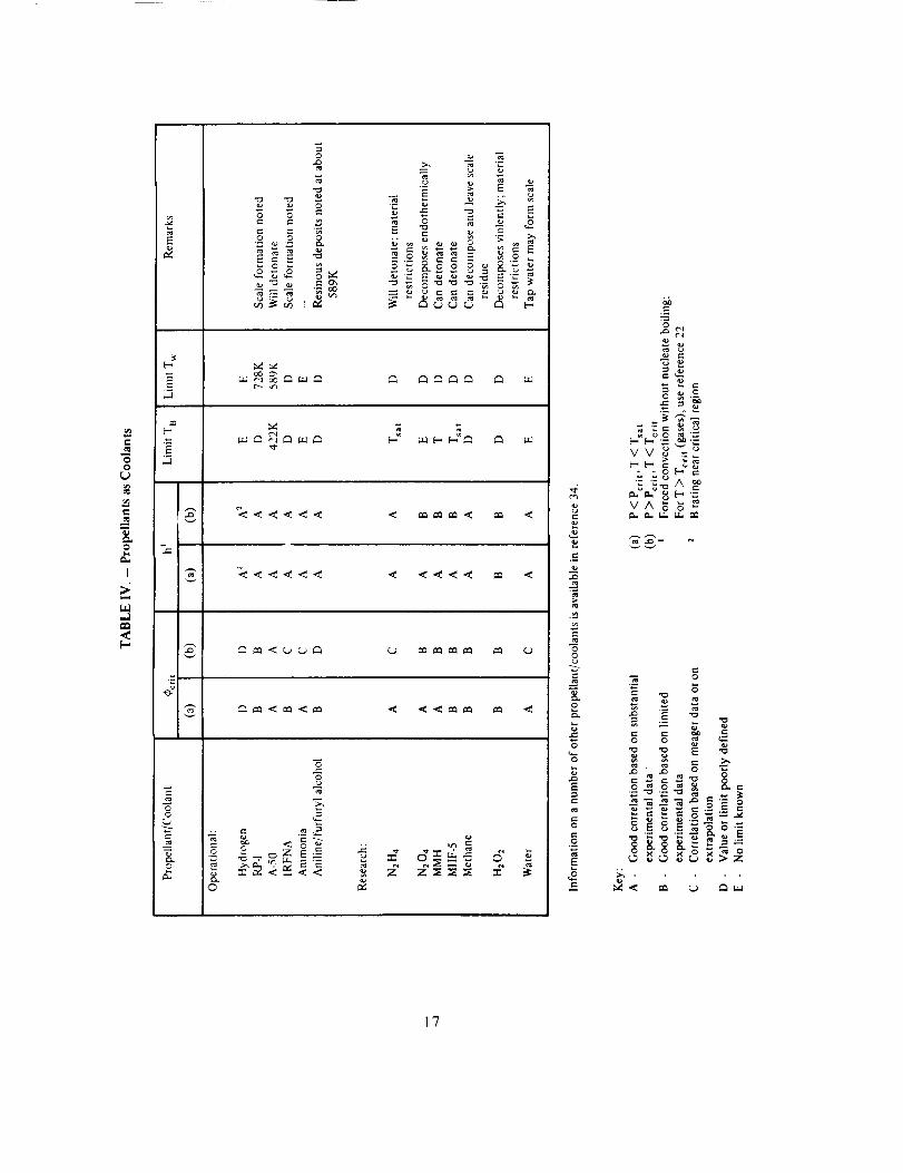
The liquid-side thermal conditions generally are much better understood and characterized.
Table IV lists propellants that have been used as coolants and provides a subjective
evaluation of the depth of information. In general, accurate liquid-side convective
coefficients are predictable for most coolants. The correlations for hydrogen were not
completely consistent until the data from many investigators were treated compositely. Thecomposite data permitted a better interpretation of the critical temperature region, where
significant transport property variations have produced results that previously were difficult
to interpret. The influence of curvature also has been recognized, and enhancement and
degradation effects are now considered. The phenomenon and effects of nucleate boiling
also are well understood. The important consideration is that in the regime of nucleate
boiling, the liquid-side wall temperature will be at or a few degrees above the saturation
temperature of the coolant. This similarity must be accommodated in the theoretical model,and, although wall temperature assumed on this basis is not absolutely accurate (because the
wall superheat is a function of the heat flux), such assumed temperature has been sufficient
for design purposes, causing at most a 50°discrepancy with a 1500°F base (28 K in 1089 K).
Correlations for the onset of film boiling (burnout) are available for most common
propellants. The burnout information has been determined in controlled experiments, inwhich round tubes are electrically heated to failure while the heat load is measured at
specific coolant velocities, temperatures, and pressures. Most of the data accumulated in thismanner have a fractional standard deviation of about 0.15. The chambers for the Titan
engines have been designed to operate at a maximum heat flux that is 15 percent less than
the heat flux that would cause tube failure, although in newer designs the value is kept atleast 18 percent below the theoretical burnout level.
Some coolants have formed residues on the liquid side of the heated wall; some havedecomposed. RP-I is noted for coking at wall temperatures above 800°to 900°F (700 to
756 K) and has produced sulfur embrittlement of nickel tubes when the sulfur content
exceeded specifications. Furfuryi alcohol has produced resinous deposits on walls at 600°F
(589 K) and above. The family of hydrazine coolants will decompose at elevatedtemperatures; most notably, Aerozine-50 has detonated when in contact with walls above
600°F (589 K). Detonation is avoided by keeping the liquid-side wall temperature below
16
00
r_
I
[--,
,..I
,.Q
-8-
0
o
0
o _ o E -=-
oz_ :_
e..
-66
o
e'_
e-.
0
E
t-
.£
E
e-
e_
eo e-
._'__ -.--.,- _., E
_.- _ "._
.-'. .'2. _
VA_
,-. = ,_
i ._oo#; ._o
17
O00°FtD<_c)K.>.t+c_tillc _._i?c'++_+1dopo+it+'<iilctic'_,iclciu,_tiiiilt+t<t<_'l>_<+it_+h_.t,<eleechacccptucliithe lon#c+it) t-c'tlttli-c'l!ic,iit< ccit+ '<titl he lilCl, >;illCC th<_ _ic'l+ ;_it:, I+Llllct il I) +lt>_+l). O\rCi _i t+Oi'iodOf linlc.
l'_vull tlIou_ll uooiiil7 lc'tluir<.,incllt<+ Call /+o t+iudit_lc'_l
occt.irrcd _+_,'11cI1 ',cccmtt+ii\ c.'llccts ',_,'cre ignorccl. \t'r'_ill I>ttrilFt_'_tSt)l1_;+
;,__<+'lli;.itu]). thurn].,ll l;iiltli__,_, h_lvu
+tt[,, ]l_t+c., t)cc+'tlrioct l()i _i llLIllil+cr _)] L
• _taglluti_>n _+i+ rucit-culation dit'{i+ oxi+t0cl in c'()+)[:tlli, t+)ti_,+ago++
• The toi;il c<>t+luct .;ii't'_l was inc.'t+c._i+ucl'+li uhtl$, t! ciuh\' il+cro:_lsin{z hull-; tcnlr_ci-_+ittii+__ ,
aild Io,vc,riu+ !lie:' Imtnt_ut h0+<il i]ux nlargin.
• ('¢+oh_i+t voluuitk's were roduc¢cl in .+ut+t+o.<udly >;atu _.irc"<t>,.but thu thuim+tl int)ctul
o'+'oi+ltl;tli) l+l-c>vet] to+ I)e innccur_ito.
• Filin t+oolii+_ (_,t_l+plutm_'ntctt to rc7c'i/tu:itlve) v,';i-, ructtiueU holow t)tirlloul levels iu
,sup!oost.'cll)' ._afc' <,ittl_ttions.
• Ill a tioiihlu-'+v_tll du._i,gi_,tit0 nlatliloid did i_c>t ttal+>:Iiiil tttu cool_tilt uilifurni]), inlo
a wiclc' p'<i+_<_tiL.,¢._inci tilt! itik.'t region I+lt.irilt_,d out.
• Wall ttiicknes_> _+1+ tow-conduclivity lll_.iteiKil _,_,+_i_, c,XOO_,s,JVc' _tt +c'l'taiil areas,
i+_articuhirlv at maHit'old :ittuchlno_lt+ _ind hiluic+++ti,:)i_s. _.tlld tl_0+¢ ai7__i+ o'+'0rht2;+it0d.
Joints _il_(.t t)ittlic'nlioi_; _trc, i+t-imc, arct_ls for tile t_'xistcl_c¢ oi f'low d[sttlri+allce+ aild result;lilt
failure, t+it'Ul-C_ttions l):.irticul:+il+ly :_ire tiroa+ (ll" t_'iiution I_oc;ill+<t+̀ tile conlt>itl:.ttion of wold
Jropthr_)u<gh i>l hr'<izc :tccumul_ition, cli_;t<>rtion, and ctilllct!lt physh:ul i'itup louds lo ilow
obstrtictioll. ,+\l_l>, undulecled l+razc voids in th0+c' _irea+ +ict _i_, I>_li'riei+s to> efficient heati r_.ins l'0 i-.
t>rcs_,uic ' dro f) has hc',.m i+_rcclictccl auuur{itcly By +tui_tlaict l+t<Jcudur_+,s Joi + calctilaling t]tlicl
flow. When c'lrt)t++ h_i\'c' t>ccurrutt, they helve !+_t'Oll c_.ttlSUCt h) i{.rlloraitcc of _tcttial conditioi+l_
+rich ;.1<_$tirt_.lCO roughl+ossu,, or ch+innel diinoi+sion+, l_+nai+ticil+at0ct |low variations have
resultc'd from ttl/)O_, worked t(;, I/.5 oi tll0 oi+igiilal dianic'tcr: ih0 fricticm l+_tctor was increased
significantly t)y thi_ ;.ilti¢)tliil c+r working +ind the wall ihici,:llg+<-;c,_ wurt., crNitic, l:,xc0ssivo
presstlre drops +tlso huvc t)c'ctlired when velocities o1 liquid c_+¢)h:tnt cxc:eodc'd 200 Prise'c:((+1.0 ln/sct:l, tq>r ]iquiU_>. tile tl_,'rn_+tillic' licact :.it hltzh vt+docilie_, magniIit+'s the c'tTc'ct of {lily
local flow tti,>tulh_.utcc. [:<+r g:tsc,_, tile y,tatld_.trtl l'_r<)cc,tttirc i_, t<; limit the velocity t<) Much 0..I
to avoid t+otcnti_il .,>ohio cll(_killu+
2.1.2 Manifolds
The primary role of the manifold is to distribute the coolant uniformly to the flow passages,
so that no passage will receive inadequate coolant flow. The degree of uniformity
established is related to the thermal margin of safety required for the specific combustion
chamber. Smooth flow must be provided at each passage inlet to preclude stagnation orrecirculation in regions of transitory detached flow.
Three kinds of coolant manifolds are used in regeneratively cooled chambers: inlet, outlet,
and turnaround. Design complexity depends on the number of coolant passes and the
extent of integration with structural support features. In some cases the manifolding is
integral with structural supports and interface flanges. For some two-pass systems, the inletmanifold is integral with the forward flange. When a nozzle extension is bolted to the aft
end of a regeneratively cooled chamber, the turnaround manifold is integral with the aftflange. The outlet manifold is always integral with the forward flange.
2.1.2.1 FLOW DISTRIBUTION
Virtually all inlet manifolds have required design iterations to overcome problems of flow
maldistribution. The inlet manifold must distribute coolant from a single source to the
coolant passages around a circumference. Inlet manifold design thus is critical because it has
prime control of the coolant distribution in the first pass of a coolant system. Flow
variations up to 20 percent have been tolerated in the first pass of a multi-pass
configuration, because the coolant is at its lowest bulk temperature and usually the thermalmargin near the inlet is wider than that near the outlet. Normally, this variation must be
reduced prior to the final pass. This reduction has been accomplished by using the inherentbalancing benefits derived from common manifolds at turnaround and transition areas.
When large flow variations have not been tolerable in the first pass, extensive analyticalbalancing, coupled with flow tests, has been used. As a result, manifold shapes have been
modified, and the inlets to the coolant passages have been tailored for uniform metering ofthe flow.
The degree of flow imbalance in parallel-circuit flow as a function of inlet and outlet
manifolding is amenable to reasonably precise analysis. For hydrogen-cooled systems, where
large density variations exist, flow uniformity is achieved almost exclusively by analyticalmethods. Parallel circuits are designed precisely in response to the properties of the
hydrogen at each station, and the manifolding is an integral part of the flow model. For
storable coolants, the design problem is not as complicated, since changes in coolant densityare not as pronounced.
The inlet manifold for fluid-cooled chambers invariably is formed in a toroidal shape. Two
theories of torus design guide the designer: (1) variable area with constant flow velocity and(2) constant area with variable flow velocity. The advantages for the tapered torus are that
19
thevelocitiesat the inlet to eachcoolantpassageareequalandthe inlet characteristicsdonot vary;the physicalsizeis small,therebyminimizingtrappedpropellantvolume(adversemasspropertiesandadversedynamics)andminimizingstructuralloads;andstagnantflowareasare avoided.The disadvantagesinclude potential adverseflow distribution duetopressuredrop aroundthe toms,anda morecomplexshapefor fabrication.In comparison,the main advantageof theconstantareatoms is that pressurelossesaroundthe toms areminimized;however,maldistributionstill resultsbecausethe inlet velocitiesto the coolantpassagesnearthe inlet of thetomsarehigherthantheyareoppositethe inlet.Flowsplittersat the inlet to a torushaveimprovedtheflow distributionin coolantsystems.Torusdesigntoday is a compromisebetweentwo extremes,andsmoothturnscombinedin manycaseswith smoothvanesareusedto achievetherequireddegreeof flow uniformity.
For double-wallchamberswith helicalcoolantflow, flow uniformity with aninlet torushasbeenachievedby keepingthe flow velocitieslow andprovidingsmoothstreamlinesof flowat theentranceto thecoolantflow section.
Turnaroundmanifoldscollect the coolantat theendof atubularpassanddirect it into thenext pass.Generally,this flow reversalis accomplishedat low velocities,which is possiblebecausethe locationis alwaysin the expansionnozzlewheretheheatloadsarelowest.Theturnaround manifold is either a commonannulusto all tubes,or it containspassagestocollect flow from onetubeanddirectit to aspecificadjacenttube.Thecommonannulusispreferredfor storablecoolantsbecauseit canevenout flow distributionprior to the finalcritical pass.Discretepassagesarepreferredfor hydrogenbecauseof theneedto balancetheflow resistancesfor eachchannelseparatelyasafunctionof the localcoolantproperties.
Outlet manifoldssimply providea meansof directingall of the coolantuniformly to theinjector. Thesemanifoldsaremadeintegralwith the forward attachmentflange;usuallythey consistof a collectionannulusanda ring of holesto matcheitherholesor anannulusin the injector. Smoothtransitionswithin thismanifoldingareusedto reduceundesirablepressurelosses.If thechamberisweldedto the injector,anannulusis providedwithin theinjector to collecttheflow prior to distributingit to the injectormanifolding.
In spite of precautionsin design,flow variationswill exist. Redesignshavebeenmosteffectivewhentheflow distributionsweremeasuredandstudiedin acold-flowfacility usingeitherliquid or gaseoussimulants.Removalof the turnaroundmanifoldhasfacilitatedtheevaluationof the first passof a multi-passsystem.Errorsin cold-flowevaluationslargelyhavebeeneliminatedby flowing to back pressureand simulatingthe operationalinletconditions.
2.1.2.2 STRUCTURE
The structural design of toroidal parts has been accompanied by small problems, but the
fabrication is well proven, with many rolled and forged parts in use. Generally, two shell
halves are welded together to form the toms; care is taken to eliminate stress concentrations
2O

the causeof leakagecannotbe assignedexclusivelyto the higherloadsthat exist in thebrazedjoints of thesechambers.The classof chambersthat incurredmoreleakagenot onlywaslessrigid but wasalsodependentonearly brazingtechniques.Theadvancementof theart of chamberfabricationhasprovidedboth strongerchambersandstrongerbrazedjoints.The accompanyingreduction in leakage,though brought about by both of theseimprovements,probablyis creditablemore to newbrazingtechniques(sec.2.7) thanto thereductionin joint loads.
2.1.3.1 THROAT REINFORCEMENT
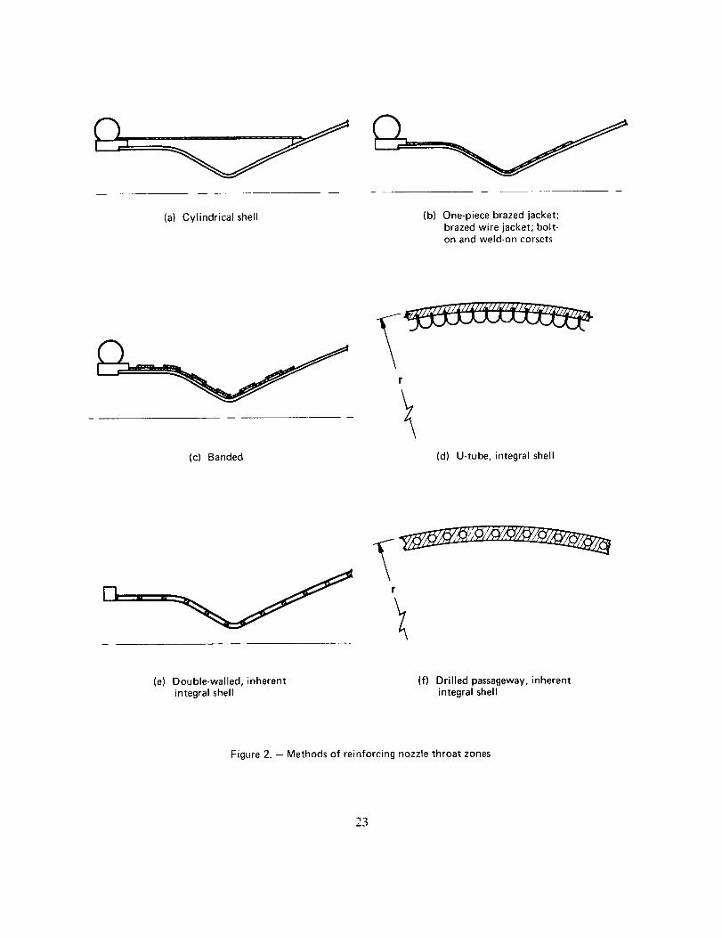
There are several operational means (table I) for reinforcing regeneratively cooled nozzle
throats against buckling. Major methods are depicted in figure 2 and include cylindrical
shells (Aerobee, Stage I Improved Titan), one-piece brazed jackets (J-2, F-l, H-l), brazed
wire jacket (Stage II Improved Titan), bolt-on corsets (Stage II Titan III), weld-on corsets(RL 10), banded (Atlas booster and sustainer), integral shell (NERVA [U-tube], Atlas
vernier [double wall] and Agena [drilled passageways]). The Titan II, X-15, and Deltachambers are wirewrapped for hoop support only and rely on the inherent strength of the
tube bundle to resist buckling.
For tubular chambers the major problem of structural support in the throat has been to
support the tubes rigidly and positively. The best (strong, low weight, uniform restraint)
support is achieved through an intimate attachment of the support structure to the tubes.
The loads are transmitted in shear from the tube bundle to the support through a brazed
joint. A high degree of intimacy is achieved with the brazed-jacket design, wherein the
jacket is brazed to a large portion of the lengths of the jacketed tubes. With this design, the
major problem has been to achieve positive attachment between the jacket and the tubes.During brazing of the one-piece-jacket design, the coolant tubes are pressed against the
jacket by a pressurized bag. This procedure was used to fabricate the F-l, J-2, and H-1
chambers, but the development of the tooling and procedures was costly and difficult. The
brazed-wire-jacket technique (Improved Titan sustainer) uses square wire spirally wrappedabout a brazed tube bundle to form a continuous shell. The wire strands are brazed to each
other and to the tube crowns. Contact between the wire and the tubes is achieved by
wrapping the wire under considerable tension about a brazed tube bundle whose roundness
has been preserved during the earlier tube-to-tube braze cycle. The tension is decreased in
decrements during wrapping to limit the shrinkage of the tube bundle.
The brazed jacket can be tapered for optimum strength and weight, and age-hardening can
provide maximum strengths for ageable materials. No critical jacket failures have occurred
unless the jackets were loaded beyond the design ultimate or the hardware contained somedeviation from the required configuration. For the brazed wire, fatigue failures have
occurred in the tube crowns between wires that were not brazed together adequately during
early development. For production hardware, quality control procedures guarantee the
absence of voids in the wire-to-wire joints. For all brazed-jacket concepts, fatigue failures
have also been experienced at the tube crowns when there was insufficient braze contact
22
at the weldjoint by penetratingtheentireshell thicknesswith the weld.Torusfabricationhasbeenbotheredby distortiondue to welding,but stepwelding,peening,andmechanicalpressinghavebeenusedsuccessfullyto minimizedistortion or to return the part to therequired form. Occasionally,the internal configurationhas beendistorted when lightstructuralareaswerepeenedexcessively.Whenintolerabledistortioncouldresult,only lightpeening,if any, hasbeenused,and inspectionby sectioningtestpieceshasbeenusedtoverifyacceptability.
Manifoldsusuallyareweldedor brazedto otherchambercomponents.Stressconcentrationsandleakpathsat brazedjoints areavoidedby maximizingthe areaof brazecontact.Whenpartsarewelded,the edgesof thepartsarepreparedfor fully penetratinggroovewelds,andthe heavierpiecesaretaperedto providea smoothstressflow from onepieceto theother.Whenmanifoldshavebeentack weldedto tubularchambersprior to brazing,thefit of thebrazedjoints often hasbeendegraded.This problemhasbeenavoidedby locating tackweldsat a position that did not distort thegapsto bebrazedor by distributingtheweldstoeliminatelocaldistortionproblems.
2.1.3 Chamber Reinforcement
The major problem of providing structural support to fluid-cooled chambers is to transmit
to heavy structural members the loads that originate at thin-walled surfaces; thistransmission must be made without degrading the performance of the cooling mechanism
and without structural failure. The three areas of structural concern are the hoop support
about the combustion chamber, the support at the nozzle throat to resist bending and
buckling, and hoop support about the expansion nozzle to resist collapse from hoop
compression. The last condition occurs during operation at sea level, where jet separation
occurs during start and shutdown and the nozzle runs overexpanded during steady-state
operation.
For structural design, limit loads and factors of safety (sec. 2.1.6) are specified to the
designer. Normally, limit loads are derived by summing maximum discrete loads. Two
factors of safety then are applied to these loads. The yield safety factor usually ranges from1.0 to 1.32; it establishes a load level below which no plastic or elastic deformation can be
tolerated. The ultimate safety factor (1.3 to 1.8) is applied to establish the load level below
which structural failure is unacceptable. These factors are applied to the physical limit loads
but not to the accompanying environmental thermal, shock, and vibratory loads. Hence,combustion chambers are designed to withstand simultaneously the sum of the ultimate
loads plus the environmental load phenomena.
One of the reasons for "retiring" tubular chambers during development programs has been
hot-gas leaks (tube-to-tube joints). On many of the programs, such leaks have developed
after large numbers of tests (more than 15). Though leaks have been more prevalent in
chambers that had less rigid structural support (banded, cylindrical shell, wirewrap only),
21
(a) Cylindrical shell (b) One-piece brazed jacket;brazed wire jacket; bolt-on and weld-on corsets
(c) Banded
r
(d) U-tube, integral shell
r
(e) Double-walled, inherentintegral shell
(f) Drilled passageway, inherentintegral shell
Figure 2. - Methods of reinforcing nozzle throat zones
23

between the jacket and the tubes. Sufficient contact is guaranteed by quality controlprocedures in response to the design requirements, and no failures have been experienced
with flight-configuration hardware.
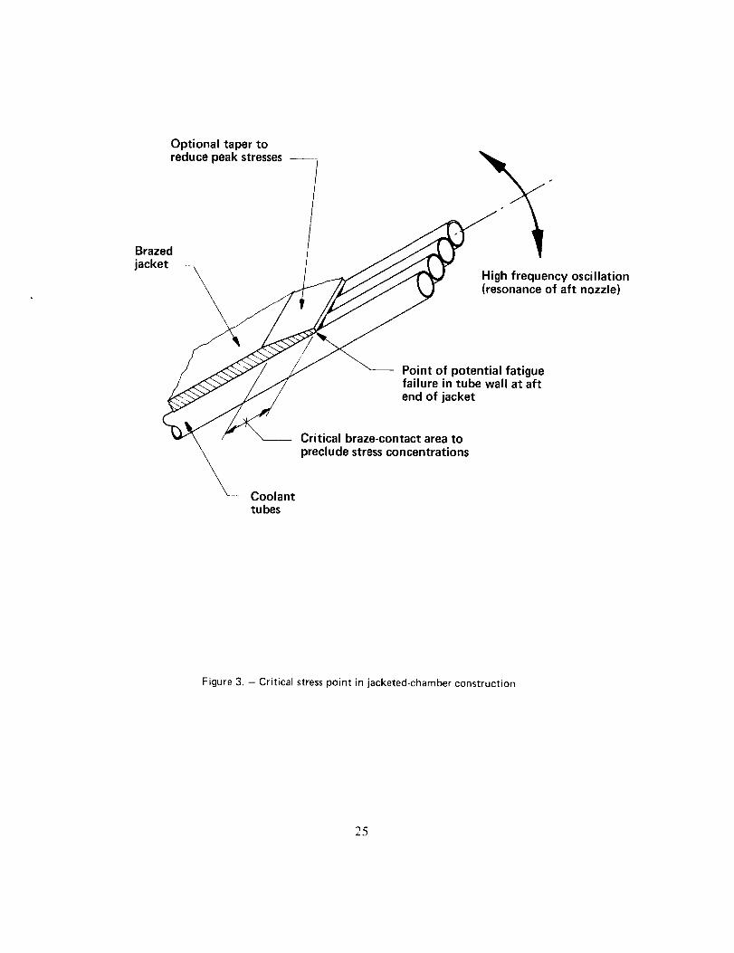
A problem that has been experienced with brazed jackets is fatigue failure of the tube
crowns at the aft end of the jacket (fig. 3). At this point, cyclic loads from structural
resonances of the expansion nozzle can be significant, and the stress discontinuity leads to
fatigue failure. The problem has been eliminated by altering the resonance characteristics of
the nozzle and by reducing the severity of the stress discontinuity at the joint. The
resonance characteristics have been altered by adding damping bands to the expansionnozzle; peak stresses at the discontinuity have been reduced by achieving a high degree of
braze contact between the jacket and the tubes in the aft 1 to 2 in. (2.54 to 5.08 cm) of the
jacket, and by tapering the thickness of the jacket in this area.
A cylindrical shell transmits loads directly from the expansion nozzle to the forward end of
the chamber and thereby reduces the loads normally carried through the throat. The major
problem is to attach the shell rigidly to the tube bundle without inducing intolerable stress
concentrations and without adversely restricting the extension of the tube bundle containedwithin the shell. In the Improved Stage | Titan, such a problem was precluded by contacting
the tubes at the aft end over a length sufficiently long to keep the local stresses low.
A shell that is integral to the coolant passages can be the simplest and surest support
structure. The NERVA U-tube concept encloses the coolant passages with a heavy structural
shell, but the fabrication is complicated by the need to ensure complete closure of the
coolant passage. The drilled-passageway concept of Agena is limited thermally by the
physical placement and shape of the drilled holes. However, the structure can be made asthick as necessary.
The standard Titan sustainer and the RL 10 use specially attached corsets; because of the
lack of integral construction between these jackets and the coolant tubes, the jackets are
heavy. The Titan sustainer uses a split, form-fitting shell that is bolted together at the seamsand welded to the forward end of the chamber at the mounting flange. The space between
the shell and the wirewrap is filled with epoxy to distribute the loads and provide some
shear-carrying capability. The Titan sustainer has flown with and without this corset, butthe structural contribution of this corset has been demonstrated by ground tests. During the
termination of a simulated altitude test (firing into a diffuser), asymmetric jet separationcan cause loads up to 1.4 times the limit load conditions. The major load element is a
dynamic side load, which has buckled the chamber in the throat region when the corset was
not attached. The subsurface wirewrap embedded in epoxy offers no capability for carrying
meridional loads. For the RL 10, an external corset is attached by welding six segments ofrolled sheet together about the tube bundle. No undercoating of epoxy is applied, since
problems have been experienced with cracking and degradation of epoxy in contact with
cryogenically cooled surfaces. The weld-on corset uses weld shrinkage to increase thecontact of the shell and the coolant tubes.
24
Optional taper toreduce peak stresses --
Brazed
jacketHigh frequency oscillation(resonance of aft nozzle)
Point of potential fatiguefailure in tube wall at aft
end of jacket
Critical braze-contact area to
preclude stress concentrations
Coolanttubes
Figure 3. - Critical stresspoint in jacketed-chamber construction
25

The Atlas and Thor chambers use primary bands that are spaced a few inches (several
centimeters) apart and are handbrazed in place. Secondary bands are welded to the primarysurface bands, bridging the gaps between them. The resultant jacket is an effective structure,
but like the welded and bolt-on jacket, it is heavy.
The Titan II booster, which has also flown on a large number of Titan Ill flights, does not
require supplemental structural support at the nozzle throat to resist buckling. The low 8:1
area ratio of the nozzle generates relatively low side loads at ignition and thrust termination.
Because of the large physical size of the throat, these loads are withstood successfully by thetube bundle alone.
Advanced work is being done with integral-shell coolant-passage construction. Reference 9
presents an evaluation of channel-wall construction where the coolant passages are integralwith the inner shell, and the outer shell is electroformed nickel. The primary purpose of this
effort was to develop efficient cooling with low-cost construction.
2.1.3.2 HOOP REINFORCEMENT
No serious hoop support problems have been encountered in any of the chamber
development programs. This absence is attributed to the simplicity of analyzing hoop loadsand designing simple support systems. Hoop support has been provided by shells in contact
with the tube crowns, wirewrapping, banding, or integral-shell coolant-passage construction.In the cases of the shells and integral structure, hoop and throat reinforcement usually are
carried by the same structure. High-strength round wire is used for Titan and the X-1 5, and
square wire for Delta. For Titan, the round wire is cold drawn, deriving added strength from
working, and is imbedded in a resin adhesive about the tube bundle to distribute the hooploads evenly. The major wire problem with Titan has been to keep the wire in place during
operation. This has been accomplished by wrapping clean wire tinder considerable tension in
a heavy bed of epoxy resin. An epoxy bed was used also for the X-I 5. As noted, Delta uses
square wire, for which no epoxy is needed since adjacent strands will not roll over eachother.
Maximum tensile strength is derived for each support method by taking advantage of the
metallurgical properties of each material. Hardenable materials often are used for jacket
designs, where, after brazing, the strength can be increased considerably by agehardening.
Non-agehardenable materials are applied after brazing if their strengths are reduced by the
brazing environment. The cold-worked steel wirewrap is applied after brazing; the only
precaution necessary is to maintain the full tensile strength of the wire where it attaches to
the wrapped segment. This is accomplished by constraining the ends of the wire withfriction forces that are derived by laying the initial and final wraps of wire in V-shaped
grooves in a circumferential band. The extreme ends of the wire then can be welded to the
band. As the hoop loads are absorbed, tension pulls the end wraps of wire into the
V-grooves, thus increasing the resisting friction forces.
26

A casewherethe absorptionof hoop loadsresultsinasecondary-stressconsiderationis thebandedchamber;it is designedto withstandbendingstressesin thetubespansbetweenthesupport bands.The double-wallchamberwith an annularcoolantpassageis designedtowithstandhoopstresseswith minimumdeflectionsothat the innerandouterwallsdonotseparate.Thesewallsneednot be rigidlyattachedto eachother if the fitup is fairly tightandthe deflectionsareminimized.Tight fits havebeenachievedby weldingtheseamsof asplit outer shelloverthe innershellandhelicalguide.Thelongitudinalweldspull thehalvestogethersnuglyaboutthe innershellstructure.Earlyproblemsof gapsformedby thermalexpansions(theAerobee)weresolvedby forcingthepartstogetherwithsprings.
2.1.3.3 NOZZLE REINFORCEMENT
The expansion nozzle is designed both to withstand hoop tension during operation in a
vacuum environment and to prevent collapse from external pressures that are greater than
the static pressures developed within the nozzle during sea level testing. Hoop tension occurswithin the nozzle wherever the static pressure of the exhaust gas is greater than the ambient
pressure; an underexpanded nozzle thus operates entirely in hoop tension. Collapsing forcesexist within overexpanded nozzles, particularly those that are designed to operate in a
vacuum environment but are ground-tested at sea level conditions. In this latter case, the
ground-test conditions usually dictate the configuration of the support structure for the
expansion nozzle.
Collapse of the expansion nozzle under start-transient and shutdown loads at finite ambient
pressure has occurred infrequently. It has been prevented by brazing rings firmly to theexterior of the nozzle. In some cases the rings have been first welded to the tubes, but
subsequently these joints have been brazed to reduce stress concentrations. The aft end of aregeneratively cooled nozzle contains a coolant manifold (in some cases, this manifold is
integral with an attachment flange for a nozzle extension), which inherently provides
considerable ring stiffiaess.
Since the support rings can resist nozzle collapse while being spaced apart from each other,
the stresses in the unsupported spans of the nozzle wall are considered. These spans act asbeams, and the bending stresses in these spans together with the nozzle forces dictate ring
spacing. In some cases, oscillation in the unsupported spans caused eventual fatigue failure
at the junctions of the tubes with the rings. This problem has been solved by reducing the
cyclic loads with damping bands or by increasing the physical area of the joints of the ringsand the tubes.
2.1.4 Interface Flange
Interface flanges attached to regeneratively cooled thrust chambers include coolant inlet and
outlet tlanges, skirt mounting flanges, injector mounting flanges, special peripheral
27

mountingpoints, and flangesfor tapoff of fluid or hot gas.Theseflangesoften containinternalflow passages,areexposedto heat,andaresourcesof stressconcentration.
The injectormountingflangegenerallyhasthegreatestnumberof designrequirementsandconstraints.For a regenerativechamber,this flangesubmitsto someor all of thefollowing:(1) internal coolantmanifoldingthat feedsfuel to the injector;(2) partialexposureto thecombustiongases:(3) integralsealjoints for the coolantand the combustiongases;(4)provision for attachment to the injector either mechanically(bolting) or physically(welding);(5) provisionfor attachmentto the coolant-passagestructureof thecombustionchamber;and(6) for 2-passcooling,integrationwith inlet manifoldingthat feedsfuel intothefirst passof thecoolantflow channels.
Injectormounting flangescurrentlyaredesignedto attachsecurelyto the coolantpassagestructurewith minimumgeometricaldiscontinuityat the joint. The secureattachmentisachievedby long,brazedshearjoints; geometricaldiscontinuitiesareminimizedby attachingthe forwardflangeto thecoolantpassagesovera longerlengthon theexteriorthanon theinterior (hot-gasside) surfaceof the passages(fig. 4). This kind of attachmentforms atransitionzonewith a broad distributionof transitionstresses.The thermalloadsto thesurfacesthat areexposedto thehot gasesarelimited by keepingtheexposedlengthshortandascloseto theinjectorfaceaspossible.Theexposedsurfaceusuallyis protectedby fuelfilm or barriercooling.If theflangeerodes,the injector invariablyis altered. The internalmanifolding (inlet or outlet), seal grooves, and threaded holes are integrated while
maintaining adequate design structure.
Skirt mounting flanges often contain coolant manifold passages; hence, these flanges submit
to some of the same constraints as the injector mounting flange. Skirt mounting flanges are
machined true to forward flanges so that the thrust vector alignment can be controlled.Since these aft flanges cannot be mounted to the required trueness, and the position cannot
be maintained during chamber braze cycles, the required trueness is achieved during a final
machine operation. Precautions are taken to ensure that this final machining does not
penetrate into the coolant manifolding. These flanges have not been subject to problems
other than minor erosion. When erosion has occurred, the erosion pattern has been used to
establish additional machining requirements; i.e., heavy or exposed areas that are damaged
by the hot gases are machined off. When heat flux at the exit is relatively high, the tubes areshaped to place the manifold out of the hot-gas stream (e.g., in the design for the J-2
engine).
Special flanges often are attached to the coolant structure for moun:ng components, for
attaching mounting struts or gimbal actuators, or for achieving gas tapoff. The local nature
of the applied loads requires special reinforcement to be used in the area of attachment.
Stress concentrations are limited by this reinforcement and by the attachment of the flangesto the main chamber body or manifold in a geometrical configuration that provides forsmooth, continuous lines of load transfer.
28

Note: Cross-hatched area shows braze contact
Torus
manifold /'1 External
Internal
I njectants _ support
(a) Integral flange/manifold
Torus /--manifold
Internal
Injectants _ support
Externalsupport
(b) Adjacent flange/manifold
Figure 4. - Injector mounting flange designs
29

2.1.5 Materials
Every major chamber development program has included material evaluation studies. Many
metallurgical problems have been experienced during these programs: chemical
compatibility with the propellants and coolants, brazeability, weldability, formability, and
maintenance of design structural properties after fabrication. These problems were not
necessarily resolved by changes in materials or by metallurgy. Table III shows the materials
ordinarily used for chamber tubes; mechanical and physical properties for these common
materials are readily obtained from sources such as MIL-HDBK-5 (ref. 23).
Since fluid-cooled chambers normally involve cooled walls with thicknesses in the range of
0.010 to 0.040 in. (0.254 to 1.02 mm), degradation of the material composing these thin
walls is intolerable. Material degradation results from chemical attack (corrosion), incipient
melting (erosion), overheating and resulting grain growth of the base metal, and thermal
cycling. In addition, material physical properties are degraded by diffusion of some braze
alloys and the constituents of some weld materials. Every chamber is subjected to thermalcycling, and every program has experienced forms of wrinkling of cooled walls and,
eventually, fractures resulting from fatigue. Thermal fatigue has been minimized by
employing ductile materials and by reducing wall temperatures in troubled areas.
For each chamber design, basic material compatibility with the propellants, reactants, and
coolants is achieved by selecting materials with excellent compatibility ratings, rather than
by compromising with materials whose compatibilities are ranked as being fairly good. This
means simply that when a compatibility problem can be avoided by material selection, it is
so avoided. In no instance is a material with questionable compatibility used. For example,
because of their high thermal conductivity, copper alloys are often considered for use in
regions where heat flux is high or where heat-sink cooling is important. These alloys havebeen used successfully with liquid-oxygen/liquid-hydrogen and liquid-oxygen/kerosene
systems, propellant combinations with which they are completely compatible; however,
copper alloys are not used with nitrogen tetroxide, other than in research studies, because
any moisture will produce nitric acid, which attacks the alloys. Similarly, series-200 nickel
has been considered for cooled surfaces that require relatively high thermal conductivity,
but because of chemical incompatibility this alloy has not been used in contact with
hydrazine or hydrazine blends.
Data on compatibility are stored by rocket engine manufacturers, but in some instances
problems associated with special uses are not documented. For example,
Although CRES 347 basically is fully compatible with hydrazine blends,
operation at temperatures in excess of 1600°F (1144 K) has resulted in
carburization of the material. This process of carbide formation within the
material, at the grain boundaries, reduces the corrosion : resistance and the
ductility of the base metal. Rapid, intergranular corrosion and cracking ensue.
Carburization has been deterred by keeping material temperatures below 1600°F(!144 K).
30

The corrosionresistanceof somehigh-carbonstainlesssteels(e.g.,CRES316) isreducedby sensitizing.Sensitizingresults from the precipitationof chromecarbidesat thegrainboundarieswhenthe materialis heldat temperaturesin therangeof 800°to 1500°F(700 to 1089K). Thelossof purechromeill the grainstructure reducesthe corrosion resistanceof the material. Often duringfabricationandoperation,the coolantpassagematerialsareheatedto or through1200°F(922 K) (brazing,annealing,welding,andhot-firing).Materialsthat canbe sensitizedsimply arenot usedfor applicationsnear 1200°F(922 K). Whenthey are used and a braze or annealcycle heats the material through thesensitizingrange,thedurationwithin thisrangeiskeptto aminimum.
Sulfur contaminationof nickel,evenin slightamounts,canproduceintergranularattack or embrittlementat brazingtemperatures.The contaminationcancomefrom a varietyof sources(grindingwheels,rubbergoods,atmosphere,etc.)duringthe manufacturingprocess.Likewise,high sulfur content in the hydrocarboncoolantcausesprogressiveintergranularcrackingof thehot-gas-sidewallsduringoperation.
Manyunanticipatedproblemswith newmaterialsandnewconditionshavebeenexperiencedby all designers;consequently,mostdesignerscontinueto usematerialswith whichtheyarefamiliar.
The choiceof materialsfor componentsthat attachto thecoolantsystemis basedon theneedfor physicalcompatibilitywith the coolantsystemas well ason thestructuralandthermal requirements.In almostall tubular systems,the structuralsupport bandsandjacketsare madefrom the samematerialas the coolant tubes.Whenthe materialsaredifferent,weldabilityandbrazeabilityhaveto beestablished.Furthermore,whendissimilarmaterialsarebrazed,materialswith similarthermalexpansioncoefficientsproducebetterresults.Whenthe useof suchmaterialsis not possible,specialdesignprovisionsaremade.For example,to reducecost,the forwardandaft flangesof theImprovedStageII Titanaremadefrom CRES347,althoughthecoolanttubematerialisHastelloyX. ThoughtheCRES347 expandsmorewith temperature,thepartsareretainedin intimatecontactfor brazingbyweldingthetubesdiscretelyto theflangesprior to brazing.Also,at theaft end,thetubesareweldedto eachother to preventgapsfrom formingbetweenthe tubes.At theforwardend, the tubebundleduringbrazingisbandedaroundthe exteriornearthe flangesothatgapsdonot form asaresultof thermalgrowth.
Generally,materialswith high ductility arechosen,becauseit hasbeenfound that localyieldingmustbe tolerated,anda ductilesystemcanredistributethe stresseswithout localfailure.Local "crippling" (plasticinstabilityresultingin rippledsurface)in thehot-gaswallsof regenerativesystemsnormallyoccursduringa firing; the causeis excessivecompressivestrain inducedin the hot-gaswallsby thecombinationof mechanicalloadsandthermallyinducedstresses.Excessivecripplingisavoidedbyproperdesign,but localminorcripplingistolerableif the tube materialhasa high ductility and will not strainhardenat operatingtemperatures.
31

Precautions are taken with the materials used for coolant systems to ensure that the strength
properties are equal to or better than those reported in the literature. The coolant passages
are shaped from or within specially worked materials. Coolant tubes, for example, are
exposed to many successive drawing and swaging cycles, with each cycle culminating in a
heat treatment. This heating is standard procedure; it relieves the residual stresses,recrystalizes some of the strained grains, and reorients the grain matrix. However, the
thin-wall material can be subjected to adverse conditions during assembly if, for example,the tubes are brazed at temperatures at which grain growth occurs. As grain size increases,
material is less ductile and more susceptible to low-cycle fatigue.
2.1.6 Structural Analysis
The problem of structural analysis of a fluid-cooled chamber or of any load-carrying
structure is to (1) define the maximum applied loads and environments and then (2)configure the structural member so that it will remain within allowable stress limits for all
failure-mode conditions. Stated another way, the design of a structure or structural
component usually is defined on the basis of the relation between the loading conditionsthat will be imposed on the structure and the capability of the structure to withstand these
loads. Limit load, design load, allowable load, nominal pressure, MEOP, design safety factor,and margin of safety are basic terms that are used to define the relation between structural
loading and structural loading capacity. These terms are defined as follows:
Limit load: Maximum expected load that will be experienced by the structure under the
specitied conditions of operation, allowance being made for statistical variation.
Design load (or stress): Product of the limit load (or pressure) and the design safety factor.
Allowable load (or stress): Load (or stress) that, if exceeded, produces structural failure.Failure may be defined as buckling, yield, or ultimate, whichever condition prevents thestructure from performing its function.
Nominal pressure: Maximum pressure to which structure is subjected under steady-stateconditions.
MEOP: The maximum expected operating pressure at any time including engine transientcondition, or 1.1 x nominal, whichever is greater.
Design safety factor: An appropriate arbitrary multiplier greater than 1 applied in design to
account for design contingencies such as slight variations in material properties, fabrication
quality, load magnitude, and load distributions within the structure. The magnitude of asafety factor is a reflection of the degree of confidence in material properties, production
processes, and the validity of the predicted usage conditions.
32
Margin of safety (MS): Fraction by which the allowable load (or stress) exceeds the design
load (or stress):l
MS- 1R
where R is the ratio of the design load (or stress) to the allowable load (or stress).
Acceptance of a structure is based on the achievement of positive margins of safety underultimate (failure) and yield (adverse yield or deflection) load conditions that are established
by factors of safety applied to the maximum predicted loads. If the stress levels exceed theallowable values, redesign is necessary. Some permanent local yielding generally is allowable.
2.1.6.1 GENERAL REQUIREMENTS
The maximum applied load is derived by summing numerous discrete loads (see Table V,
Load Sources). The basic problem is to include all important loads in the analysis, represent
each individual load accurately, and consider appropriate time-phase characteristics.
Although some loads have been inaccurately represented for some systems (notably, thethermal, transient, and vibration loads), no gross failures have occurred in prototypehardware. Failures have been local and have involved improper design practice (e.g., stress
concentration) or fabrication discrepancies (e.g., brittle weld, wall thickness deviation). The
absence of gross failure apparently is a measure of the generally conservative nature of the
design analysis and the effectiveness of the applied safety factors.
2.1.6.2 DESIGN ANALYSIS
Analyses are oriented to the specific structural failure modes peculiar to regenerative
chambers. Typical failure modes together with the location where they normally occur arepresented in table V. The modes are imposed on an analytical model that represents thechamber structure, and required wall thicknesses are determined for the important
structural members. A universal problem in the past has been the inaccurate analytical
representation of the structure. However, the techniques for stress analysis of complex shells
have developed to the point where today even the most complex structures can be analyzed
with a high degree of accuracy.
When some of the known failure modes have been ignored, some form of structural failureoften has occurred. The most common modes of structural failure in regenerative chambers
involve crippling of the heated wall (by thermal stresses), which has led to eventual fatigue
failure, and low-cycle fatigue at stress concentrations in thin walls. Another major cause of
chamber redesign has been the inability to produce a required structural fit or configuration
by the use of reasonable fabrication procedures. When a brazed joint has been required at ablind contact or over a very long length, the successful fabrication of this joint has not
33

TABLE V. - Chamber Structural Considerations
Potential Failure Mode
Chamber hoop burst
Chamber inward collapse
Chamber elastic buckling
Chamber plastic buckling
Gas-side burst
Gas-side low-cycle fatigue
Gas-side buckling (crippling)
Ambient-side wall fatigue
Wall bending at discontinuity
Wall low-cycle fatigue at discontinuity
Flange joint cracking
Manifold burst
Manifold cracking
Critical Location
Combustion chamber
Divergent section
Throat; forward end
Throat
Hot coolant-passage walls
Hot coolant-passage walls
ttot coolant-passage walls
Tube-to-support joints
Walls at flanges/support bands
Walls at flanges/support bands
Gas-side welds
Turnaround manifold
Component attachment joints
Load Sources
Chamber pressure (transient and steady-state)
Coolant pressure (transient and steady-state)
Ambient pressure
Thermal expansion (transient and steady-state)
Transient dynamic loads: pressure; thrust; thrust misalignment moments; asymmetric flowseparation; shutdown blowback
Gimbaling/snubbing
Appendages (propellant lines, component mounts)
Test fixtures (ground test, proof test, quality control)
Random engine vibrations
Vehicle accelerations
Aerodynamic drag loads
34
always been possible. This difficulty and many similar problems have been minimized in
frequency and significance through close coordination between the structural designer and
manufacturing personnel.
Structural tests for regenerative chambers are designed to verify that the structural design
requirements have been satisfied. These tests are conducted by increasing load levelsstepwise to the point of failure; measured strains at critical locations are used to verify the
analytical models. The important achievement has been to simulate all of the loads,
including pressure loads, thermal loads, and loads introduced at the interface joints. The
pressure loads are simulated by the careful positioning of pressurant seals, and the thennal
loads are simulated by additional application of pressure loading. Interface loads are
simulated by using mechanical interfaces with stiffnesses similar to the operational joint.
2.1.7 Brazing
All of the tubular thrust chambers except Delta are assembled by furnace brazing. Although
Delta chambers are produced successfully by welding, if the chamber were designed today,
undoubtedly it would be brazed. Furnace brazing has proven to be a very reliable means of
assembling coolant tubes or attaching enclosures to coolant passages. The brazed joints are
solid, ductile, durable, and can be designed to have no adverse effect on the coolant system
performance. This is not to indicate, however, that brazing is a simple, well-definedprocedure. Every program has expended much effort and many dollars to select the alloys
and define the procedures to braze chambers successfully.
Successful brazing entails, in order, (1) the definition of the optimum braze alloy, (2) the
proper preparation of the article to be brazed, and (3) the use of effective brazing
procedures. These key factors are defined by the designer and are established as specific
procedures in a fabrication specification.
2.1.7.1 BRAZE ALLOYS
There are many commercial braze alloys that have excellent capabilities for brazing the
materials used for regenerative chambers. Properties of these alloys are obtained readily in
vendor literature. Basic properties include fluidity, melting characteristics, chemistry,
ductility, and cost; all these features are considered when selecting an alloy for use. Withoutexception, ductile alloys have been chosen so that there may be some deflection without
local failure. For furnace-brazed systems, the gold- and silver/palladium-based alloys are the
most popular because of their fluidity and ductility. Used with clean hardware and in close
fitups, they tend to exhibit excellent capabilities, but they are very costly. Hand-brazing hasbeen accomplished successfully using low-melting silver-based alloys (early Atlas, Thor, and
Titan), but furnace brazing is now used almost exclusively.
35

2.1.7.2 PREBRAZE JOINT PREPARATION
The preparation of the article to be brazed is of major importance. All manufacturers have
had difficulty in obtaining a clean, close-fitting system that can be successfully brazed
without adversely affecting the geometry of the coolant or structural systems. Cleanliness
once achieved must be maintained. The parts to be brazed are cleaned by eliminating oxides,
grease, oil, and loose particles such as scale, grinding dust, and residuals from tooling
operations; commercial cleaners are used. The cleanliness is maintained during various
operations by covering the article while it is in transit or is waiting for subsequent machiningoperations. As noted in section 2.1.5, the thin walls in regenerative systems must not be
degraded by corrosion, erosion, or metallurgical change; brazing unclean parts can degrade
the material. Problems that have been experienced with unclean systems include thefollowing:
• Boron residuals from some solvents have attacked the intergranular structure ofInconel X at brazing temperatures.
Chloride derivatives from chlorinated cleaning solvents have attacked the grain
boundaries of CRES 347 material, although the corrosion is not advanced bybrazing temperatures.
• Free lead from hammers and tapping blocks have attacked the intergranularstructure of Inconel X.
The oxides of aluminum in Hastelloy X have inhibited braze flow and coverage
when the aluminum content has exceeded 0.2 percent and brazing temperatureshave been held for an hour.
Particles from grinding operations that took place near the article in the shop (in
adjacent weld booths, for example) have deposited on the specimen to be brazed.The particles are virtually impossible to remove and can have many corrosive and
inhibitive effects on the brazed specimen.
• With some stainless steels, residuals from tape that was applied to a thin wall
caused intergranular corrosion during brazing.
The fitup of parts to be brazed is different for each chamber design; however, the
controlling factors are similar. Successful brazed joints are achieved (presuming the correct
braze alloy is used, the parts are clean, and the correct furnace cycle is used) by reducingall
tube-to-tube gaps to less than 0.004 in. (0.102 ram), by juxtaposing the alloy and the gap to
be brazed, by minimizing the length of shear joints into which the braze must be drawn, byfilling voids with 100-mesh nickel chips or equivalent prior to brazing, and by ensuring that
material deflection during brazing is small and not detrimental.
36

2.1.7.3 BRAZE PROCEDURE
The actual brazing process involves the planned positioning of the article in a retort within a
brazing furnace and the provision of a controlled atmosphere and temperature surrounding
the article. The goal is to achieve uniform coverage of braze alloy at the intended joints
without incurring excessive runoff, contaminated fillets, or excessive changes in physical
geometry.
The ability to plan and control the brazing cycle and atmosphere is well demonstrated.
Generally, hydrogen as a blanketing gas is preferred because it reduces oxides oll the
specimen; however, hydrogen is not compatible with aluminum or titanium-bearingmaterials. Hydrogen is used only at very low dewpoints (less than -65°F [219 K]) so that
the quantity of water vapor in the retort is minimal. Argon often is used as a purge gas to
cool the brazed hardware, but only after the hardware is cooler than 500°to 700°F (533 to
644 K) so that surface oxidation will not result from the moisture in the argon.
The proper brazing temperatures for all braze alloys are set forth in the vendor literature,
but sometimes it is difficult to achieve these temperatures uniformly and maintain them for
the proper duration. Laboratory tests to evaluate specific braze flow characteristics usuallyare conducted, and specific evaluation is necessary when parts that are to be brazed have
large differences in mass (e.g., thin tubes and thick flanges). The flow characteristics are
studied in terms of the intended brazed joint. When gaps are small (tubes inserted into
flanges), a fluid braze is desirable, and slightly higher than normal temperatures are planned.
When braze runoff must be minimized, temperatures slightly lower than normal and short
times at these temperatures are useful. When both kinds of joints are found on one piece of
hardware, acceptable joints have been achieved by carefully determining an optimumalloy/time/temperature relationship. Superior joints have been achieved with two alloys that
have brazing temperatures within 50°F (28 K) of each other. The lower-melt alloy is placed
where high braze fluidity is desired.
The actual means of holding the surfaces to be brazed in the proper relationship (close fit
while maintaining the over-all geometric design) varies radically for each design. The
variations stem from the differences in configuration and the means of structural supportbeing attached. Adjustable rings and bands or contoured pressure bags have been used
successfully as tooling aids. When the tube bundle is to be brazed to a form-fitting externalshell, where considerable contact must be achieved between the shell and the crowns of the
tubes, the tubes are pressed against the shell by well-distributed forces derived from an
internally mounted pressure bag. This scheme is favored over previously employed,
internally mounted expansion rings. The rings were positioned and secured by hand, and
many variations in shell/tube contact were experienced, the amount depending on the
hardware and the operator. When an external contoured shell is not used, the tube-to-tube
brazing is accomplished using adjustable support rings, supplemented in some cases by tack
welding the tubes to permanent external support bands and to the fore and aft flanges.
37

Chambersthat subsequentlyare to be wrappedwith wire for hoopsupportor reinforcedwith a mechanicallyattachedcorsetarebrazedas a tubebundle,with aft reinforcementbandsand fore and aft flanges.Externaltooling,consistingof a bandwrappedabout thebundleandsecuredwith aturnbuckle,retainsthepropertube-to-tubeclearances.If feasible,thetubesaretackweldedto theforeandaft flanges.
Whensquarewire is to be wrappedand brazedinto an integralcorsetabout the throatregion(brazedwirejacket), the tubebundleis first brazedwhilepreciselyconstrainedtomaintain the external configuration.This procedureis necessaryto maintainuniformcurvatureof theexternalcontoursothat thesquarewirewill contactthecrownsof asmanytubesaspossible.After thetubesarestackedcarefullyonamandrelto achieveuniformity,adjacenttubesareprecisionweldedtogetherat threelocationscircumferentiallyalongthethroat region.Thesupportingbandson theaft nozzlealsoareattachedto thetubesby tackwelding,and thesebands,plusa mechanicallyattachedexternalhoopat the forwardend,maintaintheexternaltubecontourduringinitial brazing.
Whena pressurebagis usedto forcethe tubesagainstanexternalshellduringbrazing,it isusedalso to force the tubesagainstthe structuralhoop supportringsin the expansionnozzle.The ringsaremerelyconstrainedby the forcesof external,thermallyexpandingtooling. Whenno bagis used,the structuralbandsare fit andeither tackweldedprior tofurnacebrazingor handbrazedafterwards.Generally,it hasbeenfound that whenonesurfaceshouldbe forcedagainstanother,theuseof tooling that hasadifferentcoefficientof thermalexpansionissuccessfulin providingthedesiredforce.
Whenhardwareis not constraineduniformly, thermalgrowthcancausegaps.A bandthatwastack weldedto the coolant tubesalternatelyfore and aft (fig. 5) rotatedabout thewelds;uneventubeheightsresulted.Thesolutionto theproblemwasto weldeverytubetothebandforeandaft.
Chamberswith externalcorsetsthat enclosethe opensideof a coolant tube(U-tube)andreinforcethe structurehavegroovesin the corsetinto which the tubesareinserted.Thetubesaremaintainedin intimatecontactwith eachotherand thecorsetby forcingshimsinto thegapsin thegroovesbetweenthelegsof thetubes.
2.1.8 Chamber Assembly
The assembly of regenerative chambers is unique for each specific chamber design; in short,
no two chamber designs are assembled the same. One concept of tubular construction may
demand that the coolant tubes be brazed while pressed against a support shell, whereas for
others the shell is attached after brazing the tube bundle. However, common problems have
arisen during the assembly of most of the combustion chambers. These problems have
involved inadvertent tooling damage to thin-wall structures, weld distortion of coolant
passages, weld cracking of thin walls, and improper fit of matched parts.
38
Alternatingtack welds Coolant
tubes
Support band
Direction of undesirable
rotation during brazing
Figure 5. - Gap growth at support band with alternating tack welds
39
Although pieces are matched by design, tl_ey_raroly fit as simply as the designer intends.
Coolant tubes frequently are of poor quality in the first and final batches. Typical
imperfections are waviness, cross-sectional variations, all-to-the-low or -high side of the
tolerance range, tube twist, and inaccurate contour. First batches display these traitsbecause the producer is in the midst of perfecting his process; final deliveries have beenimperfect because marginal units, previously rejected, have been included in the critical final
shipment of stock.
Assembly is complicated further by the fact that design tolerances do not always ensure thata proven means of fabrication can be used. When the designer has established a tolerance to
prevent any chance of an interference, fit, fabrication sometimes has been impossible.Usually, where necessary, the designer compromises and relies on a statistical basis of
success, knowing that interference will occur only after an adverse stackup of manytolerances. Fitting problems have occurred where coolant tubes are inserted into flanges or
are aligned with flanges; where coolant tubes are inserted into long, close-tolerance holes;
where manifold tori are matched with mounting flanges; where expansion nozzle bands areattached uniformly to tube bundles; and where coolant tubes touch each other. These
problems have been avoided to the greatest degree when the designer was sensitive to the
problems of fabrication and assembly.
The assembly of coolant tubes involves some tack welding. The least number of weldingproblems has been encountered when laboratory studies preceded the full-scale assembly.
Typical problems have been excessive weld dropthrough into the coolant passage,
burnthrough or thinning of the coolant tube wall, degradation of the wall by voids or
inclusions, and the production of stress concentrations. In the latter instance, braze, appliedon and around the tack weld, has greatly reduced areas of high local stress.
Inadvertent tooling damage has occurred often. The problem emanates from an apparentlack of appreciation for the fragility of thin-wall surfaces. The tool designer has contributed
to the solution of this problem by consulting the design engineer prior to proceeding on tool
development. Still, damage has occurred, if not by oversight, then by malfunction of the
tool. It has been important to recognize the problem and to establish damage limits for the
hardware so that no time is lost in deriving repair procedures or conducting analytical
exercises every time damage is encountered. All programs have accepted coolant-tube
damage up to some pre-established limit. When repair was required, standard repairprocedures were developed.
Weld distortion has caused many problems of assembly. Arc welds in particular subject parts
to high heat loads, and the assembly of cooling manifolds and flanges by welding often has
affected subsequent assembly or interface points. Welding by the electron-beam process is
being used extensively to minimize weld distortion. When arc welding is used, close
tolerance requirements are avoided, or a bias is provided for the pre-weld components sothat the eventual distortion can be accommodated.
4O
2.1.9 Laboratory Proof Testing
To meet quality control requirements, fluid-cooled combustion chambers are tested as
pressure vessels in the laboratory for structural integrity and leakage; the coolant passagesare often flow tested with water or air to measure the flow resistance of the cooling circuit.
"Proof" pressure is applied to a pressure vessel at room temperature to demonstrate
satisfactory workmanship and material quality. Proof pressures normally are 20 percent
greater than maximum operating pressures; they are applied while the hardware is inspected
visually for adverse distortion. Some manufacturers inspect for leaks while holding at
proof-pressure conditions; others conduct a leak test at 75 percent of proof pressure as a
safety precaution. Current systems usually require that there be no allowable leakage.
Occasionally, a leak is detected in a configuration where the source is not clearlyidentifiable. In this event, repairs are made by guessing the location of the leak and using
substantial quantities of braze alloy for repair.
During proof and leak testing, tooling is used to support areas of the structure that must be
overpressurized for the sake of the test. Examples of such areas are the hoop restraint
required for a tube bundle prior to attaching the permanent external hoop support, and thewalls that separate the coolant from the hot gas at the forward end of the chamber. In this
latter case, a low pressure differential due to the pressure of the hot gas exists across this
wall during operation. However, in the expansion nozzle, the pressure differential becomessubstantial, and this pressure loading dictates the condition of the proof testing of the
coolant passages. With the high pressure required for proof testing the coolant passages inthe aft nozzle, tooling support is provided to walls in the combustion zone that need not be
designed for these high pressure loads. Proof testing of these surfaces is effected at reduced
pressure levels.
The calibration flow test is performed almost exclusively with water while flowing to back
pressure to prevent flow cavitation. It has been found that the inlet lines must be simulatedand the level of back pressure must be carefully defined in order to avoid a loss of flow
similarity. For hydrogen-cooled chambers, satisfactory flow calibration techniques have notbeen determined. Rather, flow tests are conducted with air during assembly to ensure that
none of the flow passages is obstructed by foreign matter.
2.1.10 Operational Problems
Two major factors influencing the ultimate design of every chamber are the operational
environment (including field service) and the interactions between the combustion chamberand the other components of the engine. The major operational problems have involved (1)
thermal damage, usually during the development phase; (2)transient and dynamic behavior
during engine testing; (3) small hot-gas leaks detected in the field; (4)vibration effects; and
(5) environmental factors.
41

Thermaldamagehas occurredduringearly developmentphasesasa result of improperinjector design;incompatibilitywith the injectorhasnot beenexclusivelythe fault of thechamber.Rather,thesetwo componentshavehadto be developedsimultaneously,withdesignmarginsfor thechamberasdescribedin section2.1.1.5.Compatibility of the injector
and chamber has been influenced by injection density, distribution, and angle; film cooling:recirculation; and the forward-end design of the chamber.
Start and shutdown transients have caused damage to regenerative chambers through both
pressure-surge and thermal effects. Satisfactory start transients have been defined ultimatelyusing trial-and-error procedures based on past experience. Water-hammer effects have been
avoided when transient-flow analyses preceded the test activity, but assumptions have been
necessary to characterize the combustion portion of the model. Generally, transient
problems are less severe for coolant systems with relatively small volumes that can be filled
quickly; in some cases system pressure drop has been compromised slightly in order to
decrease the volume. Hard starts due to large fill volumes have been softened by filling the
coolant passages with a nonreactive liquid prior to the test (e.g., in F-I and in the Titanengines.)
During shutdown, coolant tubes have been overheated when the coolant flow was broughtto a stop in the presence of continued heating, particularly when an uncooled expansion
nozzle was used (Stage II Titan). Overheating during development testing has been avoided
by purging the fluid downstream of the propellant valve through the jacket.
Also at shutdown, heat-sensitive materials have been damaged by heat soakback from the
hot segments of the chamber. When materials with limited heat resistance are used, they are
displaced from the hot-gas surfaces by at least 0.1 in. (2.54 ram) to preclude damage due toheat soakback. Where possible, the heat transmission path is designed to inhibit the flow of
heat to the heat-sensitive area (e.g., purge tubes are used to reduce heat transmitted to
epoxy bed on backside; heat is conducted away from seal surfaces).
Liquid-hydrogen coolant systems have experienced difficulties resulting from ice formation
(frozen water vapor) on the exterior of the cooled surfaces. During the development of the
RL 10, ice formation in areas where water vapor would accumulate deformed the coolant
tubes beneath the structural shell. The process of deformation was progressive with each
test, involving cyclically the collection of water vapor during chill-down, freezing and
attendant expansion that permanently deformed the coolant passages, and melting and
evaporation after the test when the hardware warmed up. The J-2 suffered similar damageduring development. For the RL 10, the problem of ice formation and damage was resolved
by sealing the critical areas from the atmosphere;for the J-2, subsurface voids were designedso that water vapor that liquified on the surface would drain off rather than collect and laterfreeze.
Another operational problem with liquid-hydrogen cooling has involved the time period for
priming the coolant system during the start transient, before ignition. It has been found that
42
a slow (10-15min) bleed-inof thehydrogenthroughthechamberprior to ignitionprechillsthe componentsto the point of thermalequilibriumwheregas-freeprimedcoolantflow isachieved.
After operation and prior to shipmentor disassembly,most regenerativechambersaredrainedand flushedto removethecoolant.Further,facility leakchecksareconductedwithwaterin thecoolantpassages,andthewateralsomustberemovedsubsequently.Drainportsare provided at low points on the chambers;theseports are cappedduring firing.Occasionally,the ports havenot beenaccessible,or they interferedwith adjacentmatingpartsand havehinderedthe attachmentof the chamberto carryingrigs.Theseproblemsweresolvedby relocatingtheportsto acceptablelocations.
Tubularchambersgenerallyarenot instrumentedeasily.Measurementsof static pressurenormallyaremadein the mountingflanges,wherea portion of manifoldingis accessible.Often, pressure-mappinghasbeencompromisedbecauseof the inadvisabilityof attachingpressureinstrumentationdirectly to thecoolantpassages.Thermocoupledatahasbeenevenmoreelusivebecauseof theprecisioninvolvedin imbeddingmicrominiaturethermocouplessuccessfullyin the hot-gaswalls of the coolant passages.Braze-patchtechniqueshaveworked well to provide temperaturedata. In somecases,when a chamberhad beenconstructedwithout properprovisionfor instrumentation,the instrumentationhadto becompromisedbecausethe chambercouldnot easilybealteredto satisfythe requirements.
Small leakshaveoccurred in the field, sometimes with the chamber mounted on a flightvehicle. These leaks have been repaired on site, usually by a team selected specifically for
this purpose. In some cases, the leaks have been accepted, and the chambers operated
successfully in flight. Similarly, handling damage is normal, and most of it is acceptable
without repair. When repair has been required, it has been expedient to make the repairaccording to a pre-established set of directions.
2.2 Transpiration Cooling
Transpiration cooling utilizes a coolant, usually one of the propellants, flowing through a
porous combustion chamber wall countercurrent to the heat conduction. Three
heat-transfer phenomena are involved in the process: (1) the coolant flowing through the
wall picks up the heat that is being conducted by the wall from the hot-gas surface; (2) the
coolant as it leaves the wall reduces the temperature of the gas in the boundary layer; and(3) in some instances the boundary-layer temperature reduction may persist downstream
from the point of injection and thereby provide downstream film cooling. Although thiscooling technique has been studied extensively, transpiration cooling of rocket thrust
chambers was not really successful until the period between 1966 and 1969 when prolonged
cooling was achieved on the programs summarized in table VI. The work has progressed to
the point that transpiration cooling is considered feasible but is not a fully developedtechnique.
43
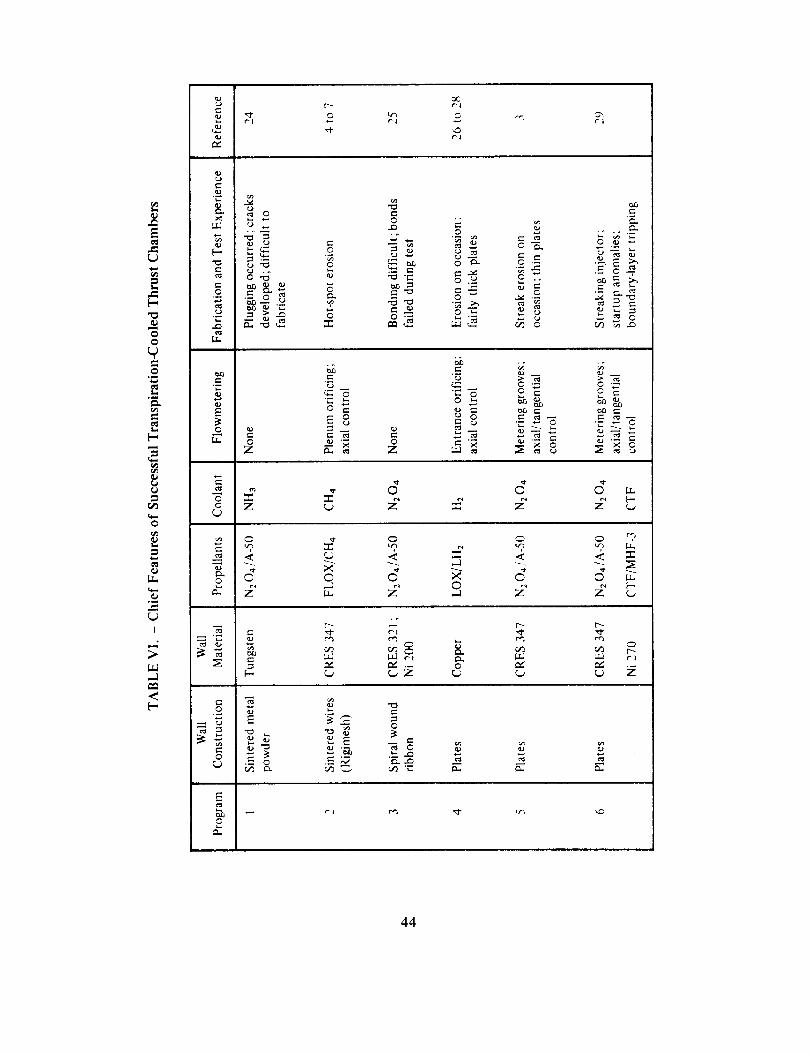
r'l0 Lt_j
_C
0 G"¢'I
Q;
E
J_
oo
r-
r_0
,_ _-_ ._._
C ¸ ._
0
0
_0
0°_
J
.=_
_ooZ
"_ _._
_-6 _'-6'," '- 0 '-
E8 _8
_'_ o = _'_
0
£ E g g¢o
= E o E _ dL 9 ,._.__
q
-1
0
_Z _
t_
t_
Z
,<
e-
.__
Q;
.._
0
0
/.- .._
o_ "."
o
44

Two types of porous walls have evolved: discrete-pore walls used in Programs 3, 4, 5 and 6
and the random-pore walls used in Programs I and 2 (table VI). Discrete-pore walls normallyhave been constructed by the stacking of plates, discrete passages being formed in the
sandwiching process. Flow control has been accomplished by tailoring the passages. The
random-pore walls are constructed by pressing metal powders or wires or felts together; the
random alignment of voids forms the passages. Flow control has been accomplished bycompartmenting and orificing. In both methods, the flow control is located away from the
heated zones. Often, manifolding concepts include orificing to produce coarse control of the
axial flow. Tables VII A and VII B, based on most of the development work done to date
and not merely on the successful programs shown in table VI, provide a fairly extensive
evaluation of both kinds of wall construction. While some of the actual problems that
occurred are shown in tables VI and VII, the most significant design problem with porouswalls has been the development of metering or orificing methods to control the coolant flow
through the porous wall while simultaneously accommodating both severe pressure gradientsand varying heat loads.
With sintered-wire random-pore construction, flow control has been achieved along thelength of the chamber by forming compartments or plenums that feed discrete zones. Each
zone is individually orificed in the unheated entrance area. This technique provides flowcontrol along the length of the chamber, but tangential control around the chamber is not
achieved, and hot-spot erosion has been observed. The erosion is caused by increased
localized pressure losses around the overheated areas that tend to divert coolant away fromthese hotter zones; this escalating diversion process has been termed "hot-spot instability".
The coolant diversion also tends to exaggerate local effects caused by injector streaking.
With the plate discrete-pore construction, both axial and tangential flow control have been
achieved by careful design of metering grooves etched into the plates so that the flow is not
influenced by variations in the heating rate. Precise designs have been developed, and theflow distribution on each plate is controlled to the point that chambers have been firedsuccessfully even with severely streaking injectors.
The analytical methods that are available for the design of transpiration-cooled chambers
have not been subjected to the "test of time"; at present, it appears possible to design a
"safe" cooling system but not an optimum one. Extensive work has been done to describe
the heat-exchange phenomena near the heated surface. Here a good understanding of local
thermal conditions is required; and, in rocket engines, confidence in this area (as noted
before) is somewhat marginal. Thus, the more sophisticated approaches do not seem
warranted at this time. Design of hydraulic systems within the walls generally involves
relatively straightforward network approaches unless random-pore concepts are used; thenthe prediction of the pressure-drop/flow relationships when heating occurs is not accurate.
In addition, "short-circuiting" of the flow by local pressure gradients or local heating oftenhas been overlooked. Studies involving structural considerations have been limited becauseno flight-type hardware has ever been built.
45
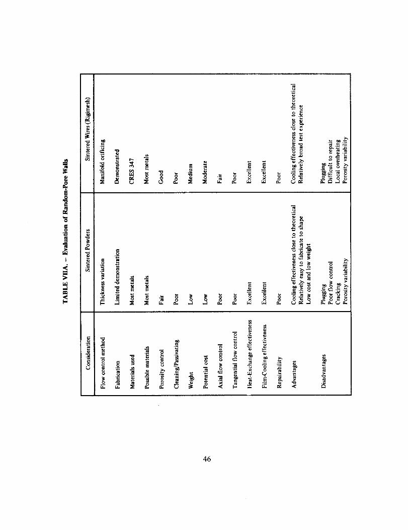
•b.J ,._
46

0
0
N
•_ _ _ _ °o o _ _ _ _ _ _ _ :
>.,
o .-
E
-_E
:E o
:_._ ._ _ "_ ._
•_ = _ _ _ ._.
.< _5
4?
Support shells, flanges, and associated structures have not been evaluated seriously, because
only workhorse-type experimental hardware has been built to date. The design of thecontour is recognized as an important consideration. Experience to date has shown that a
minimum surface area is desirable and that steep pressure gradients should be avoided.
Because experience has been limited to construction of experimental hardware, not a greatdeal is known about fabrication problems. However, certain observations unique to
transpiration-cooled systems have been made, as follows:
o Tolerance control of flowmetering orifices must be of a high order because small
variations can lead to flow rates significantly different from the design rate.
(D Small discontinuities on the gas-side surface can cause chamber failures.
Apparently the resulting turbulence not only increases the local heat transfer but
also promotes reaction between combustion gases and propellant coolant. Thiscombination of effects produces a very severe thermal environment.
c3 Porous walls contoured by machine methods can be plugged by "dirt" in the
machining oils and by material resulting from chemical breakdown of heated oil.
a Longitudinal surface welds and aligned lands on the porous surface can overheat ifthey are not adequately covered by coolant.
tD Porous materials brazed to support structures can be plugged as a result of the
strong capillary tendencies of porous media. Welding of porous media may resultin brittle areas around the weld.
Enough information now exists to show that operation of transpiration-cooled chambers is
feasible and that consistent and reproducible results may be obtained. Actually a fairamount of data of good quality exists, because most of the workhorse chambers were
well-instrumented and provided both thermal and fluid-flow data. The observations below,
therefore, have good substantiation and reflect a reasonable understanding of operational
problems:
Injector streaking is magnified by combustion at the cooled wall.
Filtering of the coolant before it enters the porous media is absolutely necessary
to prevent plugging.
Failure to insure that coolant flow is established in all parts of the chamber during
startups can lead to chamber failures in uncooled regions.
Choking of coolant flow under vacuum conditions can influence the starting
sequence, although this phenomenon has not been thoroughly examined.
48

t_ The depth of heat penetrationinto the porouswall increasesunder throttledconditionsunlessspecialflow adjustnlentsaremade.
Hot spots can developin seeminglywell-cooledzones, indicating that thepropertiesof random-poremediamaychangewith time.
t> Wall temperaturescanbeaccuratelymeasuredby smallthermocouplesimbeddedin theporouswall (especiallytheplatewalls).
Theserepresentativeproblemsshowthat manydesign,fabrication,and operationalareasmustberesolvedbeforetranspirationcoolingcanbeconsideredoperational.
2.3 Film Cooling
Nearly all fluid-cooled chambers have experienced some form of overheating from injector
maldistribution and streaking. The overheating almost always has been eliminated byrevising the injector pattern or by film cooling; in rare instances, the chamber tubes have
been redesigned for higher velocities or thicker walls.
As shown in table VIII, in all of the major regeneratively cooled chambers supplemental
cooling is derived from film cooling (which is normally provided from the injector). Film
cooling is used to (1) reduce the severity of the thermal conditions near the wall,(2) produce
a more acceptable chemical environment, or (3) achieve a combination of (1) and (2). On
occasion, film cooling is used to overcome very localized overheating simply by directing
coolant at the affected area. As noted above, injector maldistribution and streaking impactthe cooling requirements; therefore, successful chamber design dictates that both the
injector designer and the chamber designer must understand the principles of film cooling inorder to interface effectively. Their common goal is to achieve the combination of film
cooling and regenerative cooling that produces the required margins of chamber safety whilemaintaining high combustion efficiency. The principal design problems have resulted from
the inability to (1) provide an a priori prediction of film-coolant quantities, and (2) size and
arrange the flow streams so that the required quantity of coolant can be used efficiently.
In spite of many studies of film cooling carried out over the past several years, accurateprediction methods still are not available. The major unknown is the interaction of the film
coolant with the combustion gases; this interaction is known to depend on such things as
the velocity, location, and direction of injecting the film and on the energy-release potentialat the wall compared to that in the prime combustion zone, but there are additional factors
not yet identified. Also, part of the prediction uncertainty stems from the inaccuracies in
modeling the local thermal conditions that exist without film cooling; these conditions are
an essential input to the composite calculation. In a real situation, therefore, the predictionsrepresent more of a rough estimate than an absolute requirement. Consequently, when
possible, the design provides flexibility to accommodate the inevitable changes that willhave to be made.
49

E
E
o_
E
0
m,
I
.<
_ "-7 _ "7 o o
_°o _ _ _ _ _ _: < z
"2, "7 uq uq
, ._-- .__ __
o
-i
5O
A somewhat qualitative understanding exists on how the coolant streams should be cantedrelative to the wall and to each other in order to (1) minimize mixing with the reactants; (2)
maximize coverage of the surfaces to be protected; and (3) develop penetration to protect
these surfaces over maximum length. The film coolant, normally injected through a ring of
orifices around the periphery of the injector, can be directed parallel to or against thechamber wall. In most cases, a constant orifice diameter and peripheral spacing is
maintained to provide uniform injection. It is believed that when the coolant is injected as a
non-impinging stream into an unreactive environment, it traverses the chamber length moreeffectively and is presumed to provide protection for the convergent section and the throat
zone of the chamber. When protection of a forward flange surface or the forward cooling
zone is critical, greater stream spreading and sheet formation is provided by impinging the
propellant directly on the wall. Combinations of both wall-impinging and non-impinging
film-coolant streams are used for efficient protection of the entire combustion zone.
Selective orifice sizing has been used to achieve minimum film-coolant flowrates. The larger
orifices are used at hot streaks; between the hot streaks, less film coolant is provided. This
method of tailoring film coolant tends to result in circumferentially uniform wall
temperatures. Local protection has also been achieved by the addition or enlargement ofdiscrete orifices or the installation of flow tubes to place film coolant directly at heated
areas.
An alternative or supplement to film cooling is barrier cooling, in which sets of bipropellantinjection elements adjacent to the chamber wall are operated at low O/F ratio. This
procedure produces a milder thermal and chemical environment and involves morepropellant in the combustion process.
Film-coolant injection in the convergent section, via short tubes located between coolant
tubes, has been attempted during development programs; only limited success has been
achieved. Currently, this method is not an accepted technique for supplemental cooling,
because problems of manifolding, structural integrity, and assembly procedures have notbeen resolved.
2.4 Coatings
Coatings have been used on a few chambers to provide chemical and thermal protection for
cooled walls (table IX). On paper, there are many reasons for coating regeneratively-cooled
chambers (e.g., to achieve local chemical protection, lower coolant bulk temperatures,
lower heat fluxes, lower coolant pressure drop, higher chamber pressure potential, or
increased throttling range). An additional factor is the simple desire to improve performance
by replacing film cooling with coatings. Despite all these reasons, coatings remain a very
controversial subject because of their tendency to spall, delaminate, and crack. The Agena
and the X-15 chambers achieved extended lifetime by using a coating as a chemical orerosion barrier; the X-15 chamber, however, must be recoated after a set number of firings
51

L"
E
_3
E o
E o
° :21 II o
x °uJ
= .,3_
[..
o
0
7"<zu.
o• '- ,,. _ ¢._'_
,- E= _" =N
N _ _ ;_" _ _._ = = _ _=
.- _ __._ _. _ _ _ ..
o_,
_._
E
E
e.,
o
z_
E
e,.[-
0
z
.o
o
E
f.t
E
.<
Z
e-
e.,
£
o
zL_
Z ©
t_
.qx
,-4
¢q
"0
_3
._="0
.=
o
o
_=_
52
becauseof spalling.As anactualthermalbarrier,successof coatingsto dateisrestrictedto(1) the considerableprogressachievedduring laboratoryplasma-arctesting;(2) a fewdemonstrationfirings on actualchambers;and (3) progresstoward a more fundamentalunderstandingabouttherealproblem--HOWTO KEEPTHECOATINGON.
The coatingcontinuesto be consideredas an afterthoughtto or "fix" for an existingmarginaldesign.Thin monolayersof plasma-sprayedmaterialhavebeenusedto provideadegreeof chemicalprotection.Coatingsapplied in successivelayersnow are generallyrecommendedbecausethey providebetter thermalshockresistance.At one point, verythick coatingswere consideredduring developmentprograms(ref. 2), but cracking,especiallyonshutdown,wassevere,andthe rejectionof residualheatpresentedaproblem.Chemicalcompatibilityof the coatingmaterialwith the propellantsand the combustionproductsat operatingtemperaturehasbeenstudied,but coatingsthat provedtoughanderosionresistantin the laboratoryoften werefound susceptibleto erosionin an actualcombustionchamber.Methodsfor reinforcingand for attachingcoatings(e.g.,screens,wires,brazing)alsohavebeenexaminedwithout notablesuccess.
Themostsuccessfulcoatingshavebeenthoseproducedduringthecombustionprocess.Thekerosenepropellants(as well as other carbon-bearingpropellants)actually deposit acarbonaceouslayeron thesurfacesthat areexposedto fuel-richcombustionproducts.Thesedepositsprovidea tenaciouscoating,which is self-healingandeffectiveenoughsothat itmustbeaccountedfor in thethermalanalysis,sincethetotal heatrejectedto thecoolantisreduced.But, periodically,randomflaking of the depositsoccurs;hence,local areasaresubjectedto full heat loadsintermittently duringoperationaswell asduring the shortperiodwhenthecoatingfirst forms.Fueladditivescontainingsilicon(e.g.,ethyl silicateorsiliconeoil) havebeenshownto form self-renewingthermalbarriersoncombustionchamberwalls.
53

3. DESIGN CRITERIA and
Recommended Practices
3.1 Regenerative Cooling
3.1.1 Coolant Passages
3.1.1.1 BASIC REQUIREMENTS
The coolant-passage configuration shah (1) provide adequate coofing with
minimum pressure drop, (2) be low in cost to fabricate, and (3) be light in weightwhen constructed.
The practices recommended for selecting a coolant-passage configuration are summarized asfollows:
(1) For maximum heat flux below 12 BTU/in.2-sec (1.96 kJ/cm2-sec), a simplechannel-wall design is recommended.
(2) For maximum heat flux in the range from 10 to 25 BTU/in. 2-sec (1.64 to 4.09
kJ/cm 2-sec), tubular construction is recommended; however, advanced techniquesof channel-wall construction (refs. 5 through 8) may be used.
(3) For maximum heat flux above 25 BTU/in.2-sec (4.09 kJ/cm2-sec) advancedtechniques of channel-wall construction should be used.
(4) For small units, at thrust levels below 20,000 lbf (89.0 kN), simple channel-wall
construction is preferred.
(5) For minimum weight, tubular construction is recommended.
(6} For arguments of fabricability and cost, and in cases where selection is not clearly
ordained, refer to past experience; select the configuration that makes maximum
use of available data and fabrication experience.
3.1.1.2 NUMBER OF PASSES
The number of coolant passes shall be sufficient to produce effective coolingwithin the constraints of available feed pressure, simple manifolding, lowgimbaled-mass moment of inertia, and low system weight.
54

For storable coolantsat subcritical pressures,two passesnormally are recommended,becausehighercoolantvelocitiesareachievablewith largertubesthan with one pass.Arecognizablesystemadvantageis derivedfrom two-passconstructionbecausethe heavymanifoldingis located at the forward end of the chamber. The gimbaled-mass moment of
inertia is thus reduced, and the natural resonant frequency of the engine is increased.
For coolants operated over a temperature range where large differences in transport
properties and density exist, 1 or IV2 passes are recommended. This practice generates the
density change in the low-heat-flux zones, and high coolant velocities then can be achievedat the throat and in the combustion zone with nominal tube diameters. It is recommended
that liquid hydrogen be introduced in the expansion nozzle, since hydrogen as a coolant
exhibits poor qualities and rapidly changing properties near the critical point. Thus, the
cooling phase that has the poorest capabilities is isolated within the regime of lowest heatflux.
One-pass coolant systems should be considered for relatively low thrust levels when the feed
pressure is limited and two-pass cooling is not suitable.
3.1.1.3 TUBES
3.1.1.3.1 Geometry
Tube geometry shall not result in high costs or potential fabrication irregularities.
Use the simplest tube geometry possible, considering first a tube with no taper, then one
that is tapered in one direction only, and lastly one that is tapered in both directions with
the smallest diameter in the center. Each additional step of tube forming earns, of course, a
greater cooling capability, but each step also increases the cost and difficulty of tubefabrication.
For tapered tubing, it is recommended that the total taper achieved by a reduction process
(spinning or swaging) be limited to a maximum of 3:1 (diameter ratio). If a total taper
greater than 3:1 is required, use an expansion process at the large end to achieve a maximum
recommended total taper of 6:1. Beyond this ratio, excessive costs can be incurred by boththe development of the process and the increased time usually required for additional
precision working. An alternative to excessive tube working for large diameter ratios is to
employ a bifurcation joint, where two smaller tubes are joined to the large end of a singletube (see. 3.1.1.3.3).
It is recommended that the wall thickness of a coolant tube be altered along the length only
if the alteration might benefit the cooling in critical areas, control overall heat rejection, or
increase the strength of the tube; a maximum one or two thickness tapers is recommended.All tapers should be linear, with at least two inches provided as a transition section between
two zones of constant wall thickness. Guidelines for tapering wall thicknesses are as follows:
55

(1) Increase the wall thickness where a greater margin of safety is required for
coolants operated at subcritical pressures; the resultant reduction in heat flux
reduces the susceptibility to film boiling.
(2) For heat-flux-limited coolants, where the total heat rejected to the coolant must
be kept at a minimum, taper the wall thickness throughout the expansion nozzle
(starting several inches aft of the throat plane).
(3) Use thin walls where the heat loads are highest and the temperature of the gas-sidewalls must be controlled below the allowable limit.
3.1.1.3.2 Wall Thickness
Tube wall thickness shall prechtde unacceptable effects of physical and chemicaldegrada tion.
Tube walls should exceed 0.010 in. (0.254 mm) in thickness. Thinner walls have proved
susceptible to critical damage or failure through the presence of normal flaws, granular
effects in the material, erosion or corrosion due to the combustion environment, anddenting due to handling. Even though thermal and structural considerations may indicate
that tube wall thickness of 0.010 in. (0.254 mm) or less would be adequate, the troubled
history and expense of thin-wall tubes indicates that they are a poor risk.
3.1.1.3.3 Bifurcation Joints
Bifurcation joints shall provide for ease of assembly without adversely affectingthe coolant flow.
Use either of two methods for achieving bifurcation joints (fig. 6): (l) full welding, with the
tubes fitted against each other; or (2) brazing, with the secondary tubes inserted into the
primary tube. Use the welded configuration if heating is critical and the effective wallthickness must be held at a minimum. To achieve the welded joint, form the ends of the two
smaller tubes into "D" shapes, one being the mirror image of the other. Placed back-to-back,
the D-shaped ends of the two tubes are first welded together with an edge weld along the
flat line of contact. Match the circumference of the joint to the shape of the single large
tube, and join the two tubes to the primary using a butt weld (fig. 6). Use precision welding
techniques to avoid excessive dropthrough of the weld material at the joint. Do not forcethe fit of the butted joint, because deformation of the center wall of the two-tube section
(flat side of the "D") may occur during assembly. The fit should be within 0.003 in. (0.076
ram).
To achieve the brazed joint, prepare the ends of the secondary tubes as described above for
the welded joint, and weld the joint between the secondary tubes, top-to-bottom at the end.
Match the circumference of the secondary assembly to the inside dimensions of the primary
tube. Insert the secondary tubes into the primary, avoiding forcing, and braze the units
together using powdered alloy and induction-brazing techniques.
56
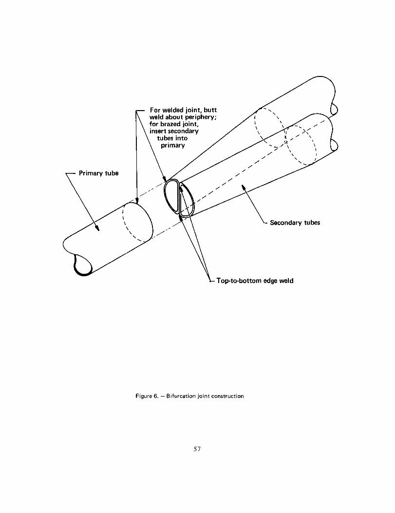
For welded joint, buttweld about periphery;for brazed joint,insert secondary
tubes into
]rimary
!
t
\\
\
Secondary tubes
Top-to-bottom edge weld
Figure 6. - Bifurcation joint construction
57

3.1.1.3.4 Tolerances
Design tolerances shall result in (1) flow control within acceptable levels and (2)
tube-to-tube and tube-to-flange fitup within limits necessary for brazing.
It is recommended that tube circumferences be held within 0.010 in. (0.254 mm) at all
stations and that tube wall thicknesses be within plus or minus 10 percent of the nominal
thickness. Control the fit of the sides of the tubes by describing at each station an included
angle equal to 360 ° divided by the total number of tubes, and by requiring that each side of
the tube be within 0.003 in. (0.076 mm) of the surfaces described by the angle. Gaps as
great as 0.006 in. (0.152 mm) will result, but work these gaps to less than 0.003 in. (0.076
mm) by careful peening and swaging techniques applied to the outer crowns of the tubes.
3.1.1.4 CHANNEL WALLS
The channel-wall configuration shall provide adequate cooling with minimum
pressure drop and shall be low in cost to fabricate.
Two alternative simple designs are recommended: (1) dual concentric shells that form a
coolant passage between the shells, and (2) a monolithic construction that contains drilled
coolant passages within a single shell. For the concentric shells, use axial flow whenever
practical and helical flow when necessary. Form the coolant channeling by attaching a
helical wrapping of wire in the gap between the two shells. Adjust the angle of the helix to
achieve the required dimensions for controlling the coolant velocity. For the drilled
passages, drill separate ringed segments of the chamber to achieve the required coolant
velocities within each segment. When assembled with manifolding at the interfaces, these
segments form a monolithic chamber construction.
Several other fabrication techniques (refs. 8, 9, and 10) merit consideration when more
complicated cooling passages are required, either to handle high heat loads or to provide
greater flexibility in the development program. These techniques include spin liners withmilled channels, cast liners with integral coolant channels, electroformed or
powder-metallurgy structures, and electroformed or brazed closures.
3.1.1.4.1 Passage Shape
The shape of coolant passages shall preclude flow stagnation and excessive
pressure drop.
In channel-wall construction, the flow passages almost invariably are rectangular in cross
section; therefore, the ratio of width to height is the shape parameter of chief concern. It is
recommended that, in regions of high heat flux, rectangular flow passages have width/height
ratios of less than two so that velocity effects at the corners of the flow channels are
avoided. Width/height ratios of eight may be acceptable provided that the channel height is
greater than 0.10 in. (2.54 mm). All chamber designs that specify rectangular channels
58

havingaspectratiosgreaterthanabout four shouldbeexaminedfor flow separationsandresultingeddyformation;usevisualstudieswith full-scaleplasticmodels.
For machined passages,surfacesfinishes should be evaluatedfor each method ofmachining- mechanical,photo-etch, electron-dischargemilling, and electrochemicalmilling;assesscarefully thesurfacefinish(root meansquare)producedby a givenmethodandtheeffectof that finishonpressuredrop.
3.1.1.4.2 Double-Wall Construction
When the flow guide is not attached to both walls, double-wall construction shall
minimize interpassage leaks.
Dimension the outer shell for a fit ranging from a slight interference to a slight clearance
(-+0.010 in. [+0.254 mm]). It is recommended that, where possible, an interference fit be
planned. When this kind of fit is not possible, and the outer shell fits to the inner shell in
two halves, weld joints should be designed to pull the two shells into sufficient contact. If
no flow bypass is tolerable, braze or weld both shells to the guide. If brazing is used, gaps
less than 0.004 in. (0.102 mm) should be obtained through tight tolerances, hand fitting,use of dissimilar metals (greater expansion for internal shell), or rolling the external surface.
3.1.1.4.3 Interchannel Areas
Regions between cooling channels shah not cause local overheating at the gas-side
surface.
When cooling is reduced by the physical presence of a wire or flow guide or by material
between drilled channels, examine the two-dimensional thermal effects. This examination
will indicate how wide the land can be and, for dual-shell construction, whether the flow
guide needs to be in intimate contact with the inner wall. To enhance two-dimensional
cooling (fin cooling), use highly conductive materials and maintain intimate contactbetween flow guides and the heated wall.
3.1.1.5 SPECIAL THERMAL AND HYDRAULIC CONSIDERATIONS
3.1.1.5.1 Gas-Side Heating
lnitial design shall be based on conservative estimates of the gas-side thermal
conditions, especially near the injector.
The procedure shown in table X is recommended for calculating gas-side heating as a first
approximation. In this procedure, the only major parameter that is influenced directly by
the injector is recovery temperature T r which is calculated using a c* adjustment term ; use a
conservative approach for determining T r by basing the c* adjustment on the maximum c*
59

0.I
0
i
&
0i
0i
L_
o
I
,--1
<
E-, _ [.,
E._ _ o
0
- E
,_ ..oo
v
E
"9,
.o
o .o
o
..o
o
._ o=0
"0
0..o
..c:
0
N
•
..o
I
o=._o=
"_ _= "_
_ _, ._.
: E-=
I I I
T i
0 __
E
8.
O4
0
0
.--I
_9
M 0
0
0.i
0
0
0
(-0
0
0
{-
i
LL.
6O
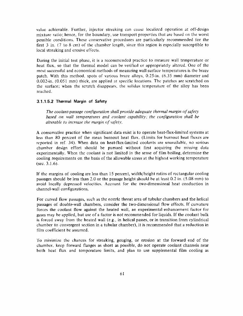
value achievable. Further, injector streaking can cause localized operation at off-design
mixture ratio; hence, for the boundary, use transport properties that are based on the worst
possible conditions. These conservative procedures are particularly recommended for thefirst 3 in. (7 to 8 cm) of the chamber length, since this region is especially susceptible to
local streaking and erosive effects.
During the initial test phase, it is a recommended practice to measure wall temperature or
heat flux, so that the thermal model can be verified or appropriately altered. One of themost successful and economical methods of measuring wall surface temperatures is the braze
patch. With this method, spots of various braze alloys, 0.25-in. (6.35 ram) diameter and
0.002-in. (0.051 ram) thick, are applied at specific locations. The patches are scratched on
the surface; when the scratch disappears, the solidus temperature of the alloy has beenreached.
3.1.1.5.2 Thermal Margin of Safety
The coolant-passage configuration shall provide adequate thermal margin of safety
based on wall temperatures and coolant capability; the configuration shall be
alterable to increase the margin of safety.
A conservative practice when significant data exist is to operate heat-flux-limited systems atless than 80 percent of the mean burnout heat flux. (Limits for burnout heat fluxes are
reported in ref. 34). When data on heat-flux-limited coolants are unavailable, no serious
chamber design effort should be pursued without first acquiring the missing data
experimentally. When the coolant is not limited in the sense of film boiling, determine the
cooling requirements on the basis of the allowable stress at the highest working temperature
(sec. 3.1.6).
If the margins of cooling are less than 15 percent, width/height ratios of rectangular cooling
passages should be less than 2.0 or the passage height should be at least 0.2 in. (5.08 mm) toavoid locally depressed velocities. Account for the two-dimensional heat conduction in
channel-wall configurations.
For curved flow passages, such as the nozzle throat area of tubular chambers and the helical
passages of double-wall chambers, consider the two-dimensional flow effects. If curvature
forces the coolant flow against the heated wall, an experimental enhancement factor for
gases may be applied, but use of a factor is not recommended for liquids. If the coolant bulk
is forced away from the heated wall (e.g., in helical passes, or in transition from cylindricalchamber to convergent section in a tubular chamber), it is recommended that a reduction infilm coefficient be assumed.
To minimize the chances for streaking, gouging, or erosion at the forward end of the
chamber, keep forward flanges as short as possible, do not operate coolant channels nearboth heat flux and temperature limits, and plan to use supplemental film cooling as
61
describedin section3.3. If possible,avoid irreversibledesignfeaturessuchasa forwardflangethat cannot be shortened,or a wall thicknessor coolingchannelthat cannotbealtered,or film coolingthat cannotbemodifiedeitherinquantity or pattern.
3.1.1.5.3 Coolant Velocity
Coolant passageways shah not cause excessive coolant velocities that result in
unan ticipa ted, in tolerable pressure drops.
Keep liquid coolants at velocities below 200 ft/sec (61 m/sec). At velocities above this,excessive pressure drops can occur because of minor variations in flow area and surface
roughnesses. It is recommended that gases be used below Mach number 0.3, with an
absolute maximum velocity of Mach 0.5. If this velocity is exceeded, sonic choking isprobable at bends, contractions, or exit/entrance regions.
3.1.1.5.4 Wall Temperatures
Wall temperatures shall remain below values at which chemical reactions thatdegrade cooling occur.
To avoid coking deposits on the cooled surfaces, do not operate with liquid-walltemperatures above 850°F (728 K) for RP-1, or above 600°F (589 K) for furfuryl alcohol.
Aerozine-50 should be used at wall temperatures below 600°F (589 K) to avoid detonation.
Generally, maintain wall temperatures below the saturation or critical temperature ofdetonable propellants when experimental data do not exist.
In the analysis of liquid-wall temperatures, do not overlook transient periods when (1)cooling might not be completely developed to the eventual full-pressure conditions, or (2)combustion has been terminated and heat soakback occurs.
3.1.2 Manifolds
3.1.2.1 FLOW DISTRIBUTION
ManiJblds shall effectively distribute the coolant flow within the allowable
pressure drop.
An annular inlet manifold is recommended; the configuration should lie between the
constant-area and the constant-velocity shapes. Dynamic head effects at the inlet to the
torus can be suppressed by using a flow splitter, which divides the flow to each side and
passes a small portion to feed the passages in the region of the splitter. Flow separationshould be prevented by shaping the vanes in conjunction with a inlet turn. For double-wall
helical passages, the inlet manifold must direct the coolant into the helix smoothly with no
stagnant areas at the edges of the passage.
62
For multi-passcoolant systems,an open annulusis recommendedfor the turnaround
manifold, providing that the flow through the first pass is satisfactorily uniform. Such acommon manifold will eliminate flow variations in the subsequent pass that could be caused
by the inlet manifolding to the first pass. Minimum flow velocity within thermal limits
should be planned for this manifold.
An alternative to the open annulus is a manifold that maintains separate circuits for the
channels. This configuration is recommended as a means to be considered for improving the
flow distribution to the first pass by providing high-resistance, parallel-flow circuitry
downstream from the inlet manifold. However, it must be recognized that the common
annulus offers a simple way to achieve uniform flow in the passes subsequent to the first,whereas a manifold that maintains separated flow will propagate flow variations throughout
the system. Therefore, in considering configurations for the turnaround manifold, compare
the flow variations for each pass against the local coolant capabilities.
The forward flange contains outlet manifolding that feeds the chamber coolant to the
injector. In this manifolding and in the inlet systems, it is recommended that normalmethods of reducing pressure drops be used even though they may present manufacturingdifficulties. These methods include round turns, smooth transitions, contoured passages, and
the use of low velocities at areas of discontinuities where no transition may be possible.
Actual flow variations should be measured in a cold-flow facility where each pass of a
coolant system should be flowed with fluids that simulate the coolant. Actual inletconditions (lines and valves) are mandatory for these tests, and back pressure should be used
to preclude cavitation within the coolant passages.
3.1.2.2 STRUCTURE
Manifolds shall not cause chamber distortion, form stress concentrations in thinmembers, or hinder subsequent assembly operations.
Minimize distortion from arc welding by (l) using more than one pass to accomplish a fillet
or _oove weld, (2) minor peening (CAUTION: If peening is desirable, the designer shouldbe consulted to evaluate the consequences of local permanent yield.), (3) step welding, and
(4) designing for minimum amounts of weld material. When gross distortion (e.g.,out-of-roundness) is inevitable, mechanical pressing to return the parts to their required
shape should be considered. Distortion from welding can be minimized by using
electron-beam welding in lieu of arc welding wherever possible.
Avoid large bending discontinuities by providing a transition section at the joints betweenthin cooled sections and heavy manifolds. The transition is accomplished by a short ( 1/2 to
1 in. [ 1.27 to 2.54 cm ] ) taper of the manifold wall (fig. 8), or by supporting a thin section
(coolant tube) over one side more than the other (fig. 4). In addition, large stresses
developed within the manifold by the pressure or appendage loads should be transmitted to
63
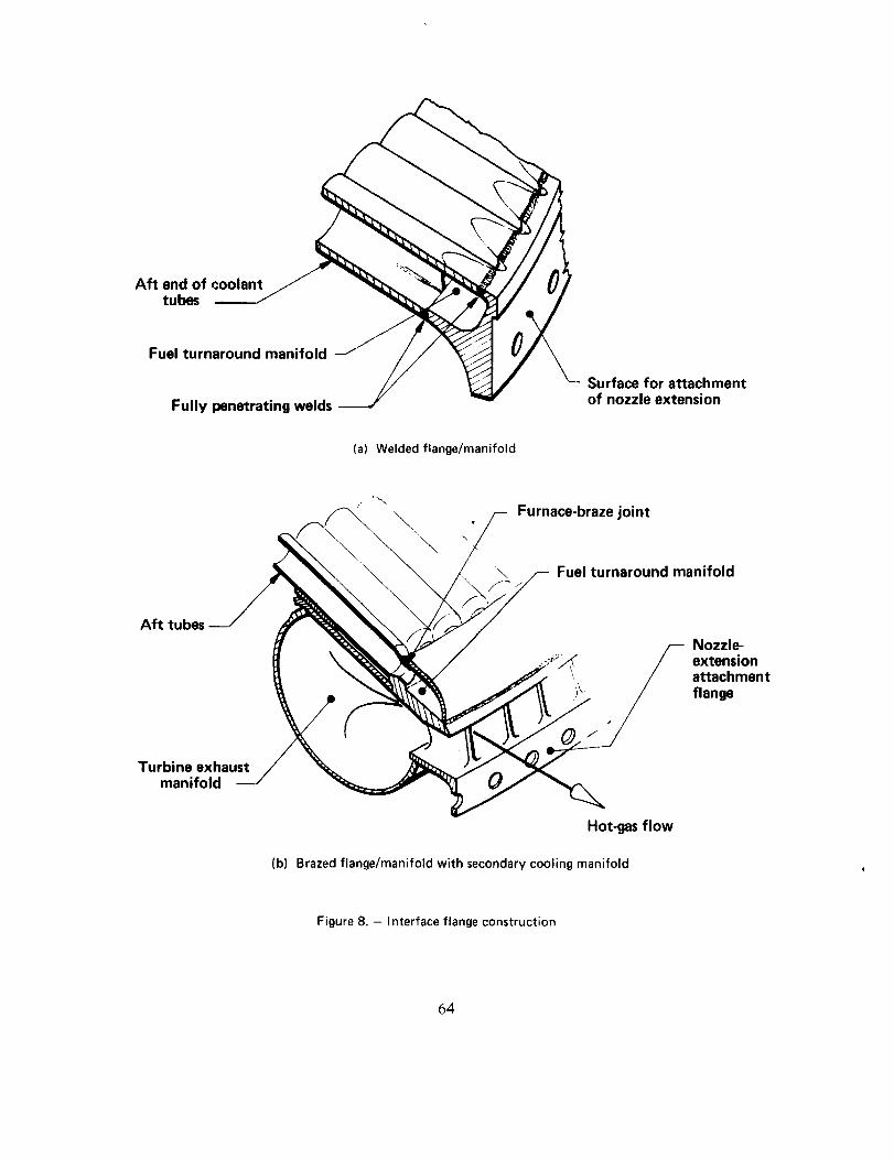
Aft end of coolant t ftubes
Fuel turnaround manifold
Fully penetrating welds
Surface for attachmentof nozzle extension
(a) Welded flange/manifold
--,\
Furnace-braze joint
Aft tubes
0/"
Turbine exhaustmanifold
Hot-gas flow
Fuel turnaround manifold
Nozzle-extensionattachment
flange
(b) Brazed flange/manifold with secondary cooling manifold
Figure 8. - Interface flange construction
64
the cooled chamber (and its structural support) through smooth lines of stress transfer. This
transfer is accomplished by geometric design that avoids discontinuities and by use of fullypenetrating weld joints.
When critical brazing operations must follow the installation of manifolds, install the
manifolds without degrading the article to be brazed. Carefully weld or fit the turnaroundmanifold to each tube so that the gaps are maintained within prescribed limits.
3.1.3 Chamber Reinforcement
3.1.3.1 THROAT REINFORCEMENT
3.1.3.1.1 Form-Fitting Shell
A form-fitting shell shall provide sufficient st "uctural restraint without allowingthe reinforced section of the chamber to fail independent of the shell.
Form-fitting brazed shells are recommended for the strongest, lightest-weight reinforcement.
Although specific analyses must be performed (sec. 3.1.6), a distributed contact area of
approximately 70 percent or greater usually is required for the tube-to-shell contact joint.
To effect this degree of contact, either stack the chamber tubes inside the contoured shell
and force them against the shell while brazing, or use square wire wrapped about tubes that
are already brazed. Braze the square wire into a rigid shell with a braze alloy lower meltingthan that used for the tube-to-tube joints. This latter method is recommended in the case of
a short shell that is needed to resist buckling in the nozzle throat area only. Forward of this
shell, the tube bundle alone must be able to carry the meridional loads. The square wires are
brazed together after being wrapped under 100 to 300 lbf (445 to 1334 N) of decreasing
tension. Brazing of adjacent strands is enhanced by knurling 0.001-in. (0.0254 mm) deep
grooves across the sides of the wire; the grooves provide lines of flow for externally applied
braze powder. The wire will contact those tube crowns that protrude above the level of the
two adjacent tubes. Areas where the wire does not contact the tubes should have shims
fitted into the gaps at the critical ends of the shell. As a result, full contact with wide brazedjoints can be achieved at the ends of the shell, where the loading is the most severe.
When it is desired to extend the shell all the way to the forward flange, it is recommended
that the tubes be brazed to a machined shell, an internally mounted, stainless-steel pressure
bag being used to hold the tubes against the shell during brazing. The bag should be quilted
for uniform pressure distribution, with walls about 0.010 in. (0.254 mm) thick. Use lowpressure (about 1/3 psi [2.3 kN/m2]) and use the blanketing gas for the pressurant. The
contour of the bag should be the same as the internal contour of the chamber. During
brazing, place high-silica-glass cloth between the tubes and the bag to prevent braze runofffrom joining the two.
65

Useeither X-rayor ultrasonictechniquesto measurethe percentageof tube-to-shellbrazecontact.X-raysoffer the additional advantage of a positive visual evaluation of the contact
area.
For maximum strength, fabricate the one-piece shell from an ageable steel, and age harden
after all brazing is completed. If the shell material is different from the tube material to take
advantage of age hardening, there must be a distinct payoff that is warranted. In general,
because of welding and brazing problems, avoid use of different materials (sec. 3.1.7.2.3).
3.1.3.1.2 Integral Support Structure
A support structure integral with the coolant passages shall not distort the
passages.
The outer wall of double-wall construction and the body of a drilled-passageway
configuration provide primary structural support. Loads in these sections together with the
loads at the hot-gas walls must be absorbed or transmitted without deforming the coolant
passages. Use the analytical procedures described in section 3.1.6 to calculate the structural
requirements, but be certain to use realistic (or conservative) thermal profiles of the walls.
3.1.3.1.3 Cylindrical Shell Support Structure
A cyfindrical shell attached to the coolant structure shall not cause excessivestress concentrations at the two planes of attachment.
The cylindrical shell (fig. 2(a)) is recommended for large systems where the nozzle throatcan withstand the local meridional loads, but some of the nozzle thrust loads must be
transmitted around the throat. Normally the shell is rigid enough to contain lightening holes
for reduced weight and visual access to the tube bundle. Of course, hoop reinforcement to
carry the pressure loads must be included.
At the forward end, attach the cylindrical shell to the forward flange by welding. Attach the
shell at the aft end to a heavy ring, brazed to at least 80 percent of the tubes for a length ofat least 1 in. (2.54 cm). For weldable tube materials with wall thicknesses in excess of 0.015
in. (0.381 mm), tack weld the ring to the crown of every tube; this procedure pulls the tube
against the ring prior to brazing. If welding is inadvisable, special tooling must be developed
to press the ring physically against the tubes during brazing. Use shims to fill gaps in excess
of 0.004 in. (0.102 mm).
3.1.3.1.4 Mechanically Attached Shell
A simple bolt-on or weld-on shell shall provide sufficient hoop restraint to the
coolant structure to preclude gross deformation of the chamber contour.
Form the internal contour of the shell to match the theoretical external contour of the
coolant structure. For bolt-on assembly, split the shell in half, provide bolting flanges, and
66
heavilycoat the innersurfaceof theshellwith freshepoxyto fill voidsduringassembly.Donot useepoxyresinswherecryogeniccoolantsareinvolvedunlessconsiderablecrackingandbreakdownof theepoxyfiller canbetolerated.
In cryogenicapplications,segmenttheshell into approximatelysix piecesandclampthemtightly in placewhile effectingthelongitudinalweld joints.Weldshrinkageautomaticallypullstheshellsnuglyaboutthecoolantstructure.
To removethe shells,cut theweldedjoints, removethebolts,and,whereepoxyisused,prytheshelloff physicallyunlessit is possibleto decomposetheepoxyby heator by chemicalmeans.
3.1.3.2 HOOP REINFORCEMENT
Hoop restraint shall prevent distortion of the chamber contour and the coolant
passages.
When hoop support of the coolant structure is required, the best procedure is to use eitherthe high strength properties of an integral shell or high-strength wire wrapped about the
chamber; either method makes maximum use of high-tensile-strength materials. The wire
overwrap should be applied under 100 to 200 lbf (445 to 890 N) tension and secured at the
ends by a friction band. When cryogenic coolants are not involved, embed round wire in
epoxy to keep adjacent strands from rolling or creeping over each other in the convergent
and divergent sections of the nozzle. Recommended alternatives to epoxy bedding arc to
overwrap the wire with a light layer of glass-filament roving or equivalent, or use square
wire.
3.1.3.3 NOZZLE REINFORCEMENT
The expansion nozzle shall withstand inward hoop loads during transient and sea
level operation; unsupported spans shall not fail in bending between ring supports.
Use bands about the expansion nozzle to absorb inward hoop loads; "I", "Vee", or "hat"
sections are recommended for the bands to increase the bending stiffness. Braze the bands to
the coolant structure; use special tooling to hold the bands in place during brazing, or tackweld the bands to the coolant structure. Tack welds are not recommended where coolant
wall thicknesses are less than 0.016 in. (0.406 mm). The bands should be spaced closely
enough to preclude bending of the cooled walls between the bands.
If the bands are welded to the tubes, subsequently braze each weld joint to distribute the
contact over a wider area. If welding is not feasible, brazing should be accomplished by
holding the rings against the nozzle with strips of a metal that has a low coefficient of
thermal expansion.
67

A turnaroundmanifoldor an attachmentflangeis an excellentnozzlesupportring and,whereused,shouldbedesignedto helpin thestructuralframe;eitheraflangeor manifoldisinherentlystiffer thanthenormalsupportband.
3.1.4 Interface Flange
3.1.4.1 STRUCTURAL EFFECTS
Interface flanges shall not cause distortion, form stress concentrations in thin
members, or hinder subsequent assembly operations.
In the design of interface flanges, as in the design of manifolds, avoid large bending
discontinuities at the joints between thin, cooled sections and heavy flanges; transmit large
stresses developed within flanges that contain manifolds or absorb appendage loads to thecooled chamber (and its structural support) through smooth lines of stress transfer.
Recommended practices are given in the second paragraph of section 3.1.2.2
When arc welding is used to effect a juncture, minimize distortion by the methods given inthe first paragraph of section 3.1.2.2.
When critical brazing operations must follow the installation of flanges, install the flangewithout degrading the fit of the article to be brazed. Carefully weld or fit the aft flange
(integral to the turnaround manifold) to each tube so that the gaps are maintained withinprescribed limits.
3.1.4.2 THERMAL EFFECTS
Heavy interface flanges shall not overheat and distort as a result of exposure tothe combustion gases.
For heavy flanges, limit the length of flange exposed to the hot combustion gases to
approximately 2 in. (5.1 cm). If supplemental cooling is necessary, use film cooling (sec.
3.3) impinging directly on the flange surface. For structural analysis (sec. 3.1.6), ensure that
correct thermal profiles are used for the flange sections. Where heat flux is high, form thetubes to place the flange out of the hot-gas stream.
3.1,5 Materials
3.1.5.1 COMPATIBILITY
Wall material shall be compatible with ttle coolant
combustion and shall not degrade unacceptably during use.and the products of
68
The thin, cooled walls of fluid-cooledchambersmust not be excessivelydegradedinductility, strength,or thermalconductivity throughexposureto either the combustionproductsor the coolant.Somedegreeof degradationis inevitable,theamountdependingupon theenvironmentandtheoperationaldemands,but minimizetheextentof changebychoosingmaterialsof excellent,knowncompatibility for the applicationandby operatingthemat thestressmarginsprescribedin section3.1.6.
It is recommendedthat the designincorporatematerialswith well-knownand provenproperties;avoiduseof unknownexoticmaterials.Onoccasion,anewmaterialmayappearbeneficial.In sucha case,commercialliteratureshouldbeconsultedfor compatibilitydata,and acceptabilityof the materialfor a givenapplicationshouldbeverifiedby a thoroughtestprogram.
For chambersthat aresubjectedto corrosiveenvironmentsin the field, stainlesssteelsornickel arerecommendedfor cooledwalls.Thesematerialsmust,of course,beprotectedfrom highly oxidizingenvironmentseitherby film or barriercoolingor by coatings(secs.3.3 and3.4), or simplyby operatingthemat safetemperatures.Carbonsteelsthat canbesensitizedshouldnot beusedfor wallswhosetemperaturesareexpectedto bein the800to1500°F(700 to 1089K) range.Usenickel-basealloys(e.g.,HastelloyX) in applicationswherewall temperaturesmustexceed1600°F(1144K) andcarburizationof thebasemetalmust be prevented.In applicationswhere0.001 to 0.005 in. (0.0254to 0.127 ram) ofcarburizationcanbe tolerated(sec.3.1.6), materialssusceptibleto carburizationmaybeusedif temperaturesdo not exceed1700°F (1200 K). Sincethe nickel-basealloysareexpensiveto handleandmachine,their useisnot warrantedunlesswall temperaturesabove1600°F (1144 K) are planned,or increasedstrengthis needed.Any contact betweennickel-basealloysandsulfur-bearingmaterialsshouldbeavoided.
3.1.5.2 PHYSICAL PROPERTIES
Wall material physical properties shall be equal to or better than the minimumvalues reported in standard literature sources or values derived by laboratory
testing.
Use MIL-HDBK-5 (ref. 23) or an equivalent reference source to identify material strengths
and other physical properties. However, some materials experience considerable changes in
properties during machining and cold working; generally, these operations tend to
strengthen a material that is annealed. Though this effect may be beneficial, corrosionresistance and ductility can be decreased. When fabrication processes have altered material
properties, these properties should be evaluated metallurgically to confirm grain orientation,
intergranular structure, grain size, and distribution of constituents. For the steels, grain sizes
in the range of ASTM 4 to 8 _ are recommended, and carbide precipitation is undesirable,
particularly when carbide chains are formed.
I Anon: ASTM Standards. Pt. 31, See. E-7, Am. Soc. For Testing and Materials (Philadelphia, PA), revised annually.
69
Generally,ductilematerialsarerecommended;their properties are particularly beneficial at
stress concentrations. Use material with 6 percent or more elongation at the operating
temperature or material having a Charpy test value of at least 15 lb-ft (20.3 N-m) at the
operating temperature. This value should be verified by test, because precipitation hardeningand cold working can decrease the ductility during fabrication.
When strengths higher than those indicated by reference sources are required, and thematerial is believed to be in a state of increased strength due to cold working, run standard
tensile tests for applicable data. This practice can result in considerable increases in
allowable working stresses with no weight increase or redesign.
3.1.6 Structural Analysis
3.1.6.1 GENERAL REQUIREMENTS
3.1.6.1.1 Model Adequacy
The structural model of the regenerative chamber shall include all significant loadsources.
Table V presents the loads to be considered. Identify each as a function of time, and analyzethe structure for the worst load combinations. Where possible, use load levels that have been
measured on similar hardware as a basis for deriving new loads, rather than relying on purelytheoretical estimates.
3.1.6.1.2 Failure Prediction
The structural design shall present a reasonable probabilio, that structural failurewill not occur during performance of the specified mission.
If load levels and safety factors are not specified for the system, it is recommended that thefollowing factors be adopted:
Pressure Factors
Proof: 1.2 x MEOP at design service temperature.Burst: 1.5 x MEOP at design service temperature.
Since tests at proof pressures at elevated temperatures for heated components generallyare not feasible, use an equivalent proof pressure at room temperature. Equivalent
pressure is derived by multiplying proof pressure by a proof-pressure factor. The
proof-pressure factor is defined as the ratio of the burst pressure at proof-test
temperature to burst pressure at the design service temperature.
70
hmertiaand Thrust Load Factors
Design yield: 1.2 x limit load
Design ultimate: 1.5 x limit load
Shock and Dynamic Load Factors
Use equivalent static loads derived from dynamic analyses and subject these loads tothe inertia and thrust load factors given above.
Temperature Factors
Design a component for the critical operating conditions created by the worst
combination of pressure and temperature occurring during engine transient and
steady-state operation. Consider in the analysis experimental thermal data obtained
from test programs for similar hardware whenever such data are available. Add a
temperature increment of 50°F (28 K) to the temperatures predicted by the thermal
analysis to arrive at maximum temperatures or thermal gradients. Apply no other
factors of safety to thermal loading.
3.1.6.1.3 Crippling and Bursting Failure
The combustion chamber shall be resistant to failure resulting from crippling or
bursting of the heated walls.
In the design of regeneratively cooled chambers, the evaluation of the failure modes of
coolant-passage burst and crippling of the heated wall (items 5 and 7 on table V) is critical
in precluding later costly redesign. The other modes shown on table V either are not unique
to regenerative chambers or do not represent areas of major redesign if the initial part hasinsufficient strength. For these other modes, use approximate and quick methods of analysis
for the initial design of the related components. Use rigorous analyses, however, for the
initial design of the coolant passages, the heated walls, and the internal structural support of
the coolant-passage configuration. During the design phase, coordinate the design with
manufacturing personnel to avoid a configuration that in fact cannot be manufactured orassembled.
3.1.6.1.4 Failure In Any Mode
The combustion chamber shall be resistant to failure in any mode.
Design for positive margins of safety (MS>0) for all modes of failure.
Define the allowable material strengths with careful consideration given to the effects of
'_ad, temperature, and time associated with the design environment. For single-load-path
71

structures,usethe minimumvalues(A values)guaranteedin reference23 for theallowableyield and ultimate properties; for multiple-load-pathstructures,use the 90 percentprobabilityvalues(Bvalues).
Categorizethestressesto ensurethat properevaluationof their importancecanbemade.Itis recommendedthat thefollowingthreecategoriesbeusedto aid in describingstresses:
Primary stress: Stress developed in response to an imposed load to satisfy the laws ofequilibrium between external and internal forces and moments. The basic characteristic
of a primary stress is that it is not self-limiting. If a primary stress exceeds the yieldstrength of the material through the entire thickness, the occurrence of failure depends
entirely on the strain-hardening properties of the material.
Secondary stress: Stress developed by the self-constraint of a structure to satisfy an
imposed strain rather than to be in equilibrium with an external load. The basic
characteristic of a secondary stress is that it is self-limiting, since minor distortions can
satisfy the discontinuity conditions or thermal expansions that cause the stress.
Peak stress: Maximum level of stress in the region under consideration. The basiccharacteristic of a peak stress is that it causes no significant distortion; it is
objectionable mostly as a possible source of fatigue failure.
Primary stresses in ductile materials. - For margins of safety based upon material yield in
non-welded areas, use an allowable stress that is the lower of the two values: (1) 0.2% offset
tensile yield strength at the operating temperature, or (2) 0.2% total plastic creep strength at
the operating temperature and required life. For welded areas, use 85 percent of the above
values unless test data justify otherwise. The calculated effective stress is the stress derivedfrom the critical yield loading conditions.
For margins of safety based upon ultimate stresses in non-welded areas, use an allowable
stress that is the lower of the two values: (1) the ultimate tensile strength at the operating
temperature, or (2) creep rupture strength at the operating temperature and required
operating life. For welded areas, use 85 percent of the above values unless test data justify
otherwise. The calculated effective stress is that derived from the critical ultimate loadingconditions.
Calculate the effective stresses on the basis of the distortion energy theory (ref. 35):
oeff ="_" (ox -ay +(oy -Oz) 2 +(Oz-Ox) 2 + 67"_y +6r_z +6r_x
72
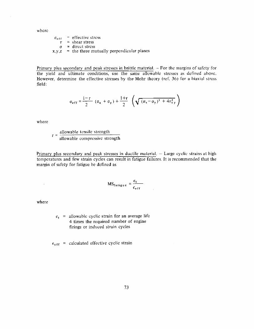
where
Ue ff
T
o
x,y,z
= effective stress= shear stress= direct stress= the three mutually perpendicular planes
Primary plus secondary and peak stresses in brittle material. - For the margins of safety for
the yield and ultimate conditions, use the same allowable stresses as defined above.However, determine the effective stresses by the Mohr theory (ref. 36) for a biaxial stressfield:
l-r l+r (_/ (Ox_ Oy)2 + 4.rx2y )=--U- (Ox T
where
allowable tensile strengthr =
allowable compressive strength
Primary plus secondary and peak stresses in ductile material. - Large cyclic strains at hightemperatures and few strain cycles can result in fatigue failures. It is recommended that the
margin of safety for fatigue be defined as
Ct
MSfatigue - -Ceff
where
allowable cyclic strain for an average life
4 times the required number of engine
firings or induced strain cycles
eerf = calculated effective cyclic strain
73

For an approximateevaluationof the allowablecyclic strain,it is recommendedthat thefollowingformulabeused(refs.37 through41):
_ 2Fty e N -_et E 2
where
Fty = 0.2%offset yield strength at the maximumtemperature of the cycle
E = Young's modulus at the maximum temperature of the cycle
e = fracture elongation
N = average cyclic life in cycles, taken as 4 times the number
of engine firings
For more accurate and detailed predictions, the methods and test data of references 42
through 46 are recommended; reference 46 is especially recommended.
For a fully constrained uniaxial thermal expansion, the effective cyclic strain equals ot A T,where ot is the coefficient of thermal expansion, and for a fully constrained biaxial thermal
expansion, it is 2 ot/X T. In general, it is recommended that the effective cyclic strain for a
biaxial state of strain be calculated from the following equation, as described in reference43:
i
6ef f =-_ _/" Cx 2 ']- CxCy -I- _y2
where ex and ey are range values for mutually perpendicular principal strains.
74

3.1.6.2 DESIGN ANALYSIS
3.1.6.2.1 Buckling Strength
The composite chamber structure shall have adequate strength to preclude elastic
or plastic buckling under ultimate load conditions.
The analyses shall demonstrate that positive margins of safety exist under the ultimate load
condition. Use the computer program described in references 47 and 48 to calculate the
general capacity of the combustion chamber for resisting lateral and axial buckling loads.
The cards and listing of this computer program are available from COSMIC, University of
Georgia, Athens, Georgia 30601.
It is recommended that a computer program similar to that described in reference 49 be
used to evaluate composite shell bending stresses;such a program accommodates anisotropic
shell properties. If the theoretical elastic lateral buckling load gives associated stresses that
are greater than the material proportional limit, estimate the plastic buckling capacity, so
that the potential buckling prior to attaining unacceptable plastic bending conditions may
be evaluated. Methods for estimating the plastic buckling capacity are given in reference 36.
3.1.6.2.2 Composite Load Resistance
A chamber that uses a shell integral with the coolant passages to resist both hoopand meridional loads shall not fail as a result of composite loading effects.
Compute the stresses by use of appropriate shell theory (refs. 50, 51, and 52). Computer
programs as described in references 49, 53, 54, and 55 are recommended. It should be noted
that the presence of a compressive meridional stress will reduce the magnitude of hoop
tensile stress at which general yielding starts.
3.1.6.2.3 Tube Compressive Strength
Coolant tubes shall not buckle under ultimate compressive loading.
The longitudinal compressive strains due to mechanical and thermal loading must not
exceed the buckling capacity of the wall. It is recommended that buckling or crippling of
coolant tubes be analyzed by the use of the techniques and findings set forth in references
42, 45, 56, and 57.
3.1.6.2.4 Tube Fatigue Strength
The heated walls shall resist fatigue failure during the required life of the engine.
Design the heated walls so the average theoretical low-cycle fatigue life of the wall exceeds
the required number of operational cycles by a factor of four. The method described inreference 44 using the thermal plus the mechanical stresses is recommended for predicting
75

low-cyclefatiguelife. To calculatestresslevelsdueto thethermalgradient,themethodssetforth in references42 and43 arerecommended.However,other methodsasoutlinedinreferences38 through43 andin reference45arealsoacceptable.
3.1.7 Brazing
3.1.7.1 BRAZE ALLOYS
Braze alloys shall be (1) compatible with materials and configurations to be
joined; (2) ductile, durable, and capable of providing a uniform joint with no
internal cracks or voids, (3) strong enough to satisfy structural requirements; and
(4) as economical as possible.
It is recommended that laboratory brazing studies be performed to supplement data found
in the literature, particularly when new material/alloy combinations are planned. Simulatedjoints heated over a range of furnace temperatures readily display the brazed joint
characteristics. The joints should be cross-sectioned, then microphotographically examined
to evaluate minimum and maximum temperatures and times, peculiarities due to the
configuration, grain structure and voids or cracks internal to the braze, and anomalouserosion or corrosion of the base metal.
It is recommended that ductile alloys be used to preclude fractures in brittle joints.
Generally, regenerative thrust chambers experience considerable material deflection withsome local yielding.
Eutectic compositions and precious-metal (gold, silver, palladium) alloys are recommendedfor close-tolerance joints because these materials have high fluidity and ductility. Some of
the multiphase alloys are useful if they can be heated rapidly above the melting point of the
high-melting phase. However, if the process is not rapid (i.e., if it takes more than 10 rain.),
the low-melting phase separates, flows into the joint, and can form a brittle or porous braze
constituency. Some large physical gaps, however, require multiphase alloys; their sluggishflow qualities are useful in filling large gaps [0.003 to 0.010 in.(0.0762 to 0.254 mm)].
Although the precious-metal alloys are expensive, they are generally recommended becauseof their fluidity, ductility, and utility. Joints that do not require tight tolerances and are not
highly stressed (e.g., heavy tube-to-tube fillets [0.040 in. (1.02 mm) or greater contact],
loose tube-to-flange joints, and external band-to-tube joints) should be brazed with less
costly alloys.
It is recommended that when light, exposed joints (e.g., tube-to-tube) and heavy, shielded
joints (e.g., tube-to-flange) are brazed simultaneously, two different but compatible alloysbe considered for use. The alloy at the flange should melt 25 ° to 50°F (14 to 28 K) lower
than the alloy at the tube joints. This layup results in uniform braze flow at both joints,such as might be obtained by brazing the different zones during separate cycles.
76
3.1.7.2 PREBRAZE JOINT PREPARATION
3.1.7.2.1 Cleanliness
The chamber shall be capable of being thoroughly cleaned at the areas to be
brazed; the cleaning materials and procedures shall be compatible with the
material to preclude the formation of residues that inhibit the braze flow; andcleanliness shah be maintained through the braze cycles.
Thoroughly clean the parts prior to assembly by use of appropriate commercial cleaners and
the processes and controls prescribed for their use. Nonchlorinated solvents arerecommended; do not clean Inconel X with solvents that contain boron. Where titanium-
and aluminum-bearing iron alloys are to be brazed, plate the stock with nickel if the
quantity of these elements is sufficient to form excessive surface oxides. For Hastelloy X,
preclude detrimental oxide formation by keeping the aluminum content below 0.15% for
normal brazing and below 0.02% for parts that are heated for periods in excess of 40
minutes to reach brazing temperatures.
It is recommended that bright annealing be considered as a process to precede a braze cycleto remove surface oxides formed during handling and storage. Some physical movement is
experienced during such annealing, similar to what would occur if the parts were being
brazed. Hence, final fitting and adjustments can be done after annealing to eliminate largegaps that might not fill with braze.
Once the individual parts that comprise a chamber are free of grease, dust, scale, and dirt to
the acceptable particulate level, the basic cleanliness should be maintained. Use special
shrouding to cover the exposed parts while they are idle or in transit, and take special
precautions (e.g., clean-room environments) to avoid contamination while the parts are
being assembled. Though tapping blocks are commonly used to hammer surfaces and parts
to assemble and achieve close fits, do not use blocks that could leave damaging residues onthe hammered surfaces (e.g., do not use lead hammers for working Inconel X). Nylon,
Teflon, or hard rubber are the recommended materials for the tapping blocks.
3.1.7.2.2 Joint Gap Size
Gap s&e at a joint shall not exceed the largest size that is known to be acceptablefor successful brazing.
It is recommended that no brazed joints be planned for gaps that exceed 0.004 in. (0..102
mm). For gaps below this size, surface tension can draw and contain the melted braze; for
larger gaps, the fluid will neither be drawn nor retained even if it is preplaced in the gap.
However, larger gaps can be successfully brazed if the gap is in a basin and the part isoriented so that gravity retains the molten alloy within the basin. Such a configuration
exists within tubular chambers at the forward end. Here, the alloy collects at the point
where the tubes enter the flange if the brazing is accomplished with the forward end down.Braze collects in a similar manner at the aft end when the chamber is brazed with the aftend down.
77

Whenlargergapsinadvertentlyoccuror mustexistby design,oftentheycanbefilled withIO0-meshchips,usually nickel, which are sintered in place. If an annealingcycle isscheduledprior to brazing,thesinteringandannealingcanbeaccomplishedsimultaneously.The resultantporousstructurewill draw brazealloy into it effectively.This procedureisrecommendedwhereinternalvoidsor loosefits exist aroundacoolanttubethat is insertedinto a flange,or wherebrazefilletsaredesirableat a tube-to-tubejoint adjacentto aflange.
Gapsno greaterthan0.004in. (0.102mm) wideareguaranteedby fitting andinspectingto0.002in. (0.051mm). Further,after brightannealingasrecommendedin section3.1.7.2.l,criticaljoints canbereinspected,andexcessivegapscanbeeliminated.
Whentubesarestackedfor a tubularchamber,inherentgapsareminimizedif thetubesareinsertedinto a precision-drilledforward flange;additionalcontrol is achievedif the aftflangeis alsoa drilledconfiguration.It is recommendedthat 0.002-in.(0.051mm)shimsbeplacedbetweenthe tubesnearthe throat plane.Minor shimmingadjustmentswill takeupslackor allowfor tight fits. Thisproceduredistributestheslackaboutthe tubebundlewhileit isbeingrigidly clamped.
3.1.7.2.3 Motion Restraint
During brazing of the chamber, there shall be no relative physical motion that
causes excessive increase in gaps at the brazed joints.
It is recommended that materials with similar coefficients of thermal expansion be used for
the elements of brazed chambers. Also, positive tooling to press joints together lightly (e.g.,pressure bag inside tube bundle to be brazed to shell, or clamping band around a tube
bundle) should be planned. When circumferential bands are tack welded to the tube crowns
to rigidify the bundle for brazing and to serve as eventual hoop-load-carrying members, theyshould be welded on both sides of the band to prevent rotation about one weld tack. If a
bright-anneal cycle is not used prior to brazing (such a cycle would form and display gapsthat would normally occur during brazing), it is recommended that a preliminaryexploratory furnace cycle be conducted without the braze alloy to evaluate relative motion
of the chamber components. Procedures can then be implemented to eliminate the adversemotion.
3.1.7.3 BRAZE PROCEDURE
3.1.7.3.1 Alloy Placement
Braze alloy shall be placed at specific locations and 0l a manner that guarantees
the successful achievement of braze coverage at the required joints.
The best practice is to apply the alloy immediately at the point where a brazed joint is
desired. For tube-to-tube joints, the braze alloy should be applied in powder form mixed
78

with anacrylic resinbinderto hold thepowderin place.Any of severalcommercialbindersareavailable,but onethat is recommendedis NicrobrazCement.Thebindermustleavenoresidueat brazingtemperatures.
For tube-to-shelljoints, alloy in foil form isrecommended.It isplacedwithin theshellpriorto stackingthetubesin place.
For brazedwireshells,foil isplacedon thecrownsof thetubesprior to wrappingthesquarewire.For band-to-bandjoints, either foil or powderis recommended.If the foil isused,itshouldbeplacedundertheband;thepowdershouldbeappliedagainsttheedgeof thebandon the uppersidewith respectto theorientationwithin thebrazingfurnace.Generally,foilis recommendedfor blindjoints wheneverit canbepreplaced.
For tube-to-flangejoints, powdershouldbeappliedaroundthetubeat thejoint. Generally,anexcessof powderisbeneficial.Referto section3.1.7.1to reviewthedesirabilityof usinga slightly-lower-meltingalloy at thesetube-to-flangejoints thanat the tube-to-tubejoints,when the two types of joints are brazedsimultaneously.
Wherevertack weldson coolant tubesexist (e.g., band-to-tubefitting, or tube-to-tuberigidity for brazed-wireshellreinforcement),alloy in powderform shouldbeappliedoverandaroundtheweld.
3.1,7.3.2 Braze Retort Configuration
The retort in the brazing furnace shall be configured to radiate heat uniformly to
hardware in an atmosphere that will not inhibit the braze flow or attack the basemetal
The furnace heats a retort that envelops the hardware and radiates heat to it. The heating
coils or source should be configured so that the retort is heated uniformly to minimize
thermal gradients (top-to-bottom) in the hardware.
The recommended atmospheres are hydrogen, argon, vacuum, and dissociated ammonia.
Generally, very dry hydrogen (dewpoint less than -65°F [219 K] ) or pure argon should be
used. For compatible materials (300- and 400-series stainless steel, some nickel-base alloys,
and oxygen-free hard copper), hydrogen is recommended;its use will retain bright surfaces.
For materials not compatible with hydrogen, argon is recommended. A vacuum is suitable
for alloys that have low vapor pressures. Dissociated ammonia should not be used with
metals that are susceptible to nitriding.
3.1.7.3.3 Retort/Chamber Mounting
The chamber shall be mounted within the retort in an orientation that enhances
braze coverage at critical /oints.
79

Usethe forceof gravity to helpdrawor collectbrazematerialat critical joints.Orientthechambersothat longshearjoints will bevertical during brazing and the source of the brazealloy will be at the top of the joint. If large fillets or collections of braze material aredesirable at certain joints, orient the chamber in the retort so that braze will tend to flow
naturally into or toward these locations.
3.1.7.3.4 Braze Joint Temperature
Instrumentation shall monitor accurately the temperatures at the joints duringbrazing.
Thermocouples mounted in close proximity (within 4 in. [10.2 cm])to the general area
that is to be brazed are recommended. The couples should be accurate within 10°F (5.6 K),and they should be mounted at a point similar in mass to the structure to be brazed. At least
two couples should be located so that they may be compared with each other.
3.1.7.3.5 Braze Cycle
The braze cycle shall produce conditions at the brazed joints necessary forsuccessful brazing.
The recommended practice is to subject the hardware tor minimum durations (2 to 3 min.)
to the temperature range at which the braze is fluid; this practice minimizes excessive
runoff. When a eutectic-type alloy with multiphase melting is used, the practice is to achieve
the temperature of the higher-melting phase rapidly, then cool down rapidly to minimizethe runoff of the lower-melting phase.
When large masses are brazed (e.g., heavy forward flanges), it is good practice to conduct a
soak period at a temperature about 50°F (28 K) below the solidus point of the alloy (sec.3.1.7. t ). The duration of this soak period should be 20 to 30 min.
The environment (sec. 3.1.7.3.2) should be maintained as required without disturbing the
part to be brazed. The dewpoint must be maintained continuously by injecting dryblanketing gas into the retort while the wetter gas is withdrawn at a low point. Though theinlet gas is dry, it is also cold, and it should not be directed at the hardware.
Conduct the cooling period by removing the furnace and dropping a water tower about the
retort. Heat, therefore, is radiated and convected to the cooling tower. At 500 to 700°F
(533 to 644 K), cooling is hastened by purging the atmosphere within the retort with large
volumes of argon. Above these temperatures, the moisture in the argon causes oxidation on
the surfaces of the hardware. Minor oxidation is not damaging unless subsequent braze
cycles are planned. Therefore, if subsequent brazing is contemplated, it is recommendedthat the parts be cooled to 500°F (533 K) before purging with argon. Otherwise, cool to700°F (644 K) before purging, so that major oxidation is avoided.
80
3.1.7.3.6 Cycle Repeatability
The design shall allow for repeated braze cycles.
It is recommended that all brazed joints be designed so that, if necessary to attain an
acceptable braze, a cycle could be repeated with additional alloy. Provide for accessibility
that will permit shimming gaps that may exist at the ends of brazed-wire jackets or under
support bands in the expansion nozzle. Plan for as many as five recycles to achieve a
completely satisfactory brazed unit, even though the basic plan may call for only one or twocycles. Recycle as many times as necessary, but do not accumulate a time-temperature
exposure that causes excessive grain growth, degrading grain-boundary precipitation, or
corrosive attack of the base metal by the braze alloy.
Two cycles at different temperatures should not be conducted before the acceptability of
the first braze cycle is confirmed. This practice precludes a situation where the higher
temperature cycle must be repeated and thereby jeopardize the condition of a lower-melting
alloy at other locations. Similarly, cycles in which the orientation is important must be
protected during subsequent repair cycles in other areas. Physical shielding with up to 12
layers of high-silica-glass cloth is recommended to prevent remelting in critical areas during
repair cycles.
Where small areas are void of braze, hand repair with lower-melting alloys is recommended.
3.1.8 Chamber Assembly
3.1.8.1 PASSAGE DEGRADATION
The coolant passages shall not be obstructed by weM dropthrough, nor shall thethin walls within cooled chambers be degraded by tack welds or stress
concentrations.
Minimize the degree of weld dropthrough at tack welds and weld joints on thin-wall coolant
passages by evaluating samples and establishing controllable procedures. When the
dropthrough is significant and could cause up to a 5-percent restriction, it is recommendedthat uniform tacks be effected for all of the tubes. Do not allow restrictions above 5
percent. Where the welds exist, evaluate the metallurgy of the base metal
microphotographically for acceptability, and establish procedures to avoid weak joints. As
noted previously, braze around the tack welds on the walls of the coolant passages to
strengthen the local area and to provide a greater distribution of the local stresses.
3.1.8.2 CHAMBER DEGRADATION
Combustion chamber fabrication procedures and test fixtures shall not damage
critical surfaces of the hardware.
81

Reviewthe following test fixturesand proceduresto identify configurationsor situationsthat coulddamageor degradethechamber:throatplugsusedfor pressurechecking;mandrelor tube support methods,which may overstresstube crowns during braze cycles;contaminationof tubes,whichmayoccurduringheat treatingor whichmay becausedbycompoundsusedduringcleaningand forming;and protectivecoversfor the endsof thechamber.
3.1.8.3 CHAMBER DENTS
The combustion chamber shall be capable of incurring minor dents that do not
jeopardize its structural integrity or serviceability.
It is standard practice to accept chambers that contain some dents if no failure will result
from the dent. Each dent requires individual attention. Mild dents in the divergent section
are routinely accepted. Dents between the throat and injector are not. These dents must be
evaluated to determine if they will (1) reduce coolant flow, (2) perturb the gas-side
boundary layer, (3) interfere with liquid-side cooling capabilities, or (4) fail under fatigueloading. For the evaluation of low-cycle fatigue, it is recommended that a comprehensive
test program, similar to those described in references 42 and 45, be accomplished todetermine the acceptability of dents.
Monitor all dents during the development program to aid in setting realistic damage limits.Establish the limits in terms of numbers, size, and shape of the dents.
3.1.9 Laboratory Proof Testing
3.1.9.1 TEST OBJECTIVES
Proof attd leak testing of the pressure-containing structure shall verify structuralintegrity without degrading other parts of the structure in any way.
Proof testing according to the definitions of section 3.1.6.1.2 is required for pressure vessels.Proof test all pressure-bearing structures and sub-structures relative to the maximum
pressure for each; i.e., the chamber should be tested relative to the maximum chamber
pressure, and the coolant passage should be tested relative to the maximum passage pressure.While each part is being tested, it is important that other lower-pressure elements are not
overloaded. Support these areas on the hot-gas side while the passages are tested to proof
pressure conditions; test the lower-pressure areas to proof conditions during another test.
3.1.9.2 LEAK DETECTION
The coolant system shall be capable of being checked for leaks so that leakage andsource may be identified.
82

Ensurethat all areasof thepressurevesselareamenableto leaktestingbyvisualobservationor pressure-decaymethods.Providevisualaccessibilityin somemannersothat the locationof the leak canbediscerned.If suchaccessibilityis not obvious,considera leaktestwherethepressurantis appliedin theoppositedirectionto thenormalpressure.
3.1.9.3 FLOW CALIBRATION
Flow calibrations shall provide flow-resistance data sufficiently accurate to be
used effectively in subsequent engine balance calculations.
The recommended practice is toemploya test facility that uses water at rated flow and atthe rated flow + 10 percent ; average these data. Use the engine lines between the valves
and the chamber, and preferably include the valves. Maintain a back pressure of at least 100psi ( 689.5 kN/m 2 ) to prevent flow cavitation within the flow passages.
For hydrogen-cooled systems, it is recommended that both air and water be used for thecalibration fluid. Correlate the calibration data with hot-fire data, and continue the
calibration procedures until either a lack of correlation is found or a positive, useful
correlation develops. If no correlation exists, discontinue the flow calibrations.
3.1.10 Operational Problems
3.1.10.1 TRANSIENT OPERATION
The chamber shall not incur thermal damage from transient operation during startor shutdown.
Configure the coolant system so the coolant flow will be distributed uniformly about the
chamber before injection into the combustion zone commences. To achieve this condition,
consistent with recommended practices for designing manifolds (sec. 3.1.2), use common
manifolds (annuli) wherever possible, particularly at the inlet, at the turnaround point, andwithin the outlet manifold.
For areas that rely heavily (or completely) on film cooling for protection during steady
state, provide thicknesses that will diffuse local heating by conduction during start-transient
conditions. This precaution is particularly recommended when an oxidizer-rich start is used
and initial high heat loads must be dissipated into heavy walls rather than allowed to raise
the temperature of thin ones above the failure point.
With cryogenic coolants, anticipate that lengthy (as much as several hours) prefire chilldown
may be required for engine system purposes.
83

3.1.10.2 POSTFIRE HEATSOAK
Chamber components that are susceptible to thermal damage shall not be
overheated and damaged by postfire heatsoak,
This problem usually can be countered by standard system procedures such as water flushes
and purging, but be cognizant of the locations of heat-sensitive materials and evaluate the
potential for damage. Non-metallic seal surfaces and epoxy closures can be degraded byheat; displace these elements sufficiently far from exposure to hot areas or protect them
with postfire purges or water flushes. Seals that are overheated during heatsoak periods can
be replaced, of course, but this is expensive. Rather, separate heat-sensitive seals from hot
gases by at least 0. I in. (2.54 mm).
3.1.10.3 WATER-VAPOR TRAP
A combustion chamber cooled by cryogenic fluids shall not contain structural
voids that trap water vapor.
It is recommended that the design preclude exposed voids (e.g., shell-to-tube gaps) or that
exposed voids possess ample drainage when the chamber is mounted in conventional firing
attitudes. Provide ample drainage by maintaining the drain path at the same dimension as
the void, without flow restriction.
3.1.10.4 DRAIN PORTS
The combustion chamber shah contain accessible drain ports for removing
residual coolant from the coolant system.
Consider all firing and transporting positions to identify the low points in the manifolding.
Locate the ports at these low points and ensure accessibility while the chamber is on the test
stand or in holding fixtures; ensure that the ports do not interfere with mating parts (e.g.,covers, lines, and other adjacent hardware) or hinder the attachment of the chamber to
carrying rigs.
3.1.10.5 INSTRUMENTATION
Initial designs shall provide for sufficient instrumentation to describe grosscharacteristics of the coolant system; eventual production designs shah provMe
for temperature and pressure probes adequate to produce satisfactory operationaldata.
84

For evaluationof distributed effects during development tests, it is suggested that coolantinlet, turnaround, and exit conditions be measured at a minimum of three different
circumferential orientations. Measurements of hot-gas wall temperatures at a minimum of
three axial locations in the combustion zone and two aft of the throat are advised, the
recommended method being the braze-patch technique (sec. 3.1.1.5.1). Use this aggregate of
data to evaluate streaking, discontinuities, and the accuracy of the thermal model.
For production, limit the instrumentation to single measurements at the inlet and exit
points only. Select the locations to be representative of a mean value, and ensure that they
do not interfere with mating parts or hinder the attachment of the chamber to carrying rigs.
3.1.10.6 HANDLING AND TRANSPORTING DAMAGE
The coolant system shah be capable of withstanding normal impact and handling
damage; if required, repair of such damage shall be feasible.
As described in section 3.1.8.3, most normal handling damage will be acceptable without
repair. However, some need for repair should be anticipated, and procedures should beevaluated and established beforehand. Generally, damage to single tubes of tubular
chambers may be repaired by one of two methods. One is "windowing" and patching, a
process wherein a piece of the wall that contains the damage is removed, and a form-fittingpatch is welded in place; an X-ray evaluation is advised. The other is "zipper welding,"
wherein the tube is sliced open and spread apart, the damage is repaired, and the tube is
reformed to its original shape with the slit welded shut. This method is also recommended
for non-tubular chambers. It is recommended that for large areas of damage in tubular
chambers, sections of several tubes be replaced. Remove unacceptable dents by the most
appropriate of several methods: (1) hammering through an access provided by splitting the
wall of the passage on the back side, (2) "windowing," (3) internal swaging through anaccess path peculiar to the chamber, or (4) applying heat to the dent while the coolant
passage is pressurized to low pressure.
3.2 Transpiration Cooling
3.2.1 Mechanical Design
3.2.1.1 CHAMBER CONTOUR
The chamber contour shall minimize (1) the amount of surface area that must be
cooled and (2) the magnitude of local pressure gradients.
85
A tradeoffstudyshouldbemadeof performance,amountof coolant,andthecontour;theextent of tradeoff dependsto a largedegreeon the quality of the injector and the L*requiredto producegoodperformance.Thefollowingrecommendationsshouldbeusedasguidelinesin selectingthe contour: (1) useconicalshapeswherepossible;(2)avoid highcontractionratios;(3) avoidlargecontractionangles;and(4) minimizethedistancebetweentheinjectorandthe throat.
3.2.1.2 WALL MATERIAL
Porous wall materials shall have a proven history of reproducibility.
Only two porous walls can be recommended at this time: the discrete-pore walls formed by
stacking thin-grooved plates, and the random-pore walls formed by compartmented sinteredwire screens.
3.2.1.3 FLOW QUANTITY
The (initial) coolant flow shall provide sufficient overcooling to allow for the
uncertainties in the thermal and hydraulic prediction models,
Ideally, the coolant flow distribution should be based on experimental heat-transfer dataobtained from the actual injector that will be used. If these data are not available, the
following procedures are recommended: (1) for discrete-pore systems, use the analyticalmethods outlined in reference 58 to predict flow rates; (2) for random-pore systems, use the
simple method of Rannie (ref. 59); (3) calculate the heat-transfer coefficients by themethod outlined in table X; (4) do not anticipate laminar boundary layers; and (5) use at
least twice the calculated coolant flow rates in initial testing, if possible, and plan to back
off gradually.
3.2.1.4 PRESSURE DROP
The allowable pressure drop shall provide for an extensive flowmetering network.
A significant amount of pressure drop must be available for flowmetering. Furthermore, the
available drop must also be adequate to develop a "hardened system" that will not be proneto flow chugging. It is recommended that the driving pressures be at least 15% greater than
the maximum anticipated local pressures.
3.2.1.5 HEAT LOAD VARIATION
The coolant flow shall accommodatevariations.
both axial and tangential heat load
86

The needfor axial flow control to produceoptimum(minimum)coolant requirementsisgenerallyrecognized.It may well be,however,that tailoring the flow to accommodatetangentialvariationsdue to streakinginjectorsis the limiting problem.Without tangentialcontrol, onemustsetthe flow rateto coolthehottestzonesaroundthechamber,andsincethesemayrepresentonly a smallpercentageof the total surface,themajor portion of thechamberis significantlyovercooled.It is recommended,therefore,that (1) streakingbeminimizedand(2) provisionsfor tangentialaswellasaxialmeteringbeprovided,especiallyin thecombustionzone.
3.2.1.6 FLOW-CONTROL SIMPLICITY
The coolant flow control shall require a minimum of hardware manipulation.
Since the need for flow adjustments has been emphasized, it is necessary that the design
incorporate methods that will facilitate these adjustments; the types of methods depend, of
course, on the basic chamber design. The following are recommended considerations: (1)flowmetering external to the chamber permits varying the flow to individual axial sections;
(2) removable housings can provide access to internal orifices that should be resizable; and
(3) sets of orifices that can be short-circuited by a machining process can provide a simple
means to reduce flow.
3.2.1.7 FLOW-CONTROL THERMAL PROTECTION
Flow metering shall not be affected by the heat load to the wall.
A heat-conduction analysis is required to ensure that the flowmetering devices are notoverheated. Recommended methods available to isolate them include use of a material with
lower thermal conductivity, longer conduction distances, minimum conduction areas,
maximum wall-to-coolant contact area, and higher coolant flow rates.
3.2.1.8 FLOW-CONTROL CHARACTERISTICS
The hydraulic characteristics of individual circuits within the flowmetering
network shall be known accurately.
Schedules should be established so that (1) the hydraulic characteristics of various
components (e.g., the wall material and the orifices) can be measured, (2) the characteristicsof individual circuits can be measured, and (3) the total component can be tested. A
comparison of measured data with predicted behavior is the only check that is available toensure that the components will work as expected.
87

3.2.1.9 FLOW-CIRCUIT STRUCTURE
The porous wall and components within the hydraulic circuit shall not buckle as a
result of pressure loading.
The porous wall normally will not be used for pressure containment; this is supplied bysome type of reinforcing housing. However, pressure differentials across orifices and across
the porous wall may be very significant, especially during startups and shutdown. Thus, the
entire hydraulic circuit should be evaluated to ensure that localized distortion cannot occur.
3.2.1.10 HOT-SPOT INSTABILITY
Local wall failures shall not result from hot-spot instability.
Hot-spot instability occurs when the heat-exchange portion of the flow network has enough
hydraulic resistance to affect the flow. Thus, local overheating generates an increase in flowresistance, diverting coolant flow from the place that actually needs more flow. The
following steps are recommended: (1) eliminate localized hot zones due to the injector; (2)
avoid nonuniform porosity that may initiate the hot spot; (3) compartmentalize the surface
to isolate damage and to help restrict flow to preferred directions; and (4) make the
hydraulic resistance of the heated zone a negligible portion of the overall resistance.
3.2.1.11 NOZZLE-EXTENSION LOSSES
The location of the nozzle-extension attachment shah minimize coolant losses.
Thermal conditions below the throat require continuation of transpiration cooling into the
divergent section. It is recommended that a nozzle extension be attached as close as possible
to the throat; this location will minimize cooling losses, reduce fabrication problems, and
avoid possible very low pressure zones. Extension attachment may be facilitated by using
the lower transpiration sections to film cool upper sections of the extension.
3.2.2 Fabrication
3.2.2.1 PREVENTION OF PLUGGING
The porous wall shah not be subject to plugging.
Filtering during operation is fairly obvious - but anything flowed through the wall at any
time must be filtered, no matter whether the flow is through the normal entrances or back
88
throughthe chamberside.Thefilter sizeshouldbeadjustedto catchparticlessmallerthanthe smallestcoolant passagein the porousmedia.If this size is unknown,a seriesofexperimentsshouldbecarriedout to determinethefilteringrequirement.
Porouswallsareespeciallyvulnerableto brazeplugging.All brazingspecificationsshouldnote the capillarynatureof porouswallsandspecialprecautionsshouldbe takento avoidcontamination.Duringanybrazingit is recommendedthat (1) minimumamountsof brazematerialbeused,(2) drainpathsandcollectionpointsbeidentified,(3) dewettingagentsbeusedjudiciously,(4) chambermovementbeavoided,and(5) braze-furnacegasesbe filtered.
All machiningproceduresshouldbe reviewedto ensurethat contaminationof the porouswall cannotoccur.Machiningporousparts is in an innovativestageandno standardizedmethodsareestablished.It is recommendedthat the followingprecautionsbetakenduringmachining:(1) flow filteredoil throughthewallduringelectricaldischargemachining- thisaction minimizesbut doesnot eliminatecarboncontamination;(2) flow filtered nitrogenthrough the wall during any dry machiningprocess;(3) considerwax impregnationtoprotect poresduringmachining;and (4) avoidoverheatingthe wall anytimeit containsadecomposablematerialthat leavesaresidue.
3.2.2.2 WALL BENDING LIMITS
Physical bending of the porous wall shall not result in serious distortion of the
porous matrix.
The random-pore materials normally must be bent to form the chamber contour. The radiusof curvature cannot be so small as to alter significantly the hydraulic characteristics of the
porous wall or produce residual stresses. Since little is really known about these fabrication
limits, it is recommended that the limits be determined experimentally.
3.2.2.3 LOCALIZED OVERHEATING
The design shall contain no uncooled welds or aligned bands that can produce
localized overheating.
Lands and welds should be located in the chamber so that cooling is provided by carryover
from passages above these uncooled zones.
3.2.2.4 SURFACE ROUGHNESS
The chamber surface shall be smooth enough to avoid creating flow disturbances.
89
Therough-surfaceeffect is relatedbasicallyto boundary-layertripping.Whiletheminimumsizefor a flow-disturbingprotrusioninto the streamis not known,significantoverheatinghasbeenobservedwith protrusionsapproximately0.005in. (0.127ram)in heightabovethechambersurface;therefore,it is recommendedthat the surfacefinishbeat leastsmoothenoughto precludeprotrusionsof thissize.
3.2.3 Operation
3.2.3.1 START SEQUENCE
The startup sequence shall establish proper coolant flow before ignition occurs.
Startups of transpiration-cooled chambers have proved to be of particular concern. It is
recommended that the following be given special consideration to ensure that a safe startup
will occur: (1) ignition should not occur until coolant flow is established in the longest flow
path; (2) precooling may be necessary to avoid choking with non-cryogenic coolants; (4)
all the circuits must be full, with no gas pockets, or backflow of combustion gases mayoccur; (5) overcooling in the steady state may be necessary to overcome a transient
problem; and (6) manifold sizes should minimize transient times.
To minimize potential chamber damage, temperatures at the gas-side surface should be
monitored during the initial flow-adjustment testing. The most successful programs to date
have had small thermocouples (0.010 to 0.020 in. [0.254 to 0.508 mm]) imbedded in theporous materials to monitor surface temperatures; these fast-response measurements
actually have been used to terminate the firing if temperatures become excessive. This
procedure is recommended when practical.
3.2.3.2 COMPONENT GROWTH
Component growth during firing shall not produce detrimental surfacediscontinuities.
The chamber may often be built up from a series of segments that can distort, grow, or shift
during the firing, thereby producing boundary-layer trips . An analysis of this growth
potential should be made. If a strong tendency exists, it is recommended that additional
coolant be introduced above the potential trip location.
3.2.3.3 WALL REPAIR
For a test chamber, the porous wall shall be repairable.
9O
Everychamberrun to datehaseventuallysufferedsomedamage;often the damagewasalocal zone of erosion.The possibilityof local damageshouldbe anticipatedand repairmeansestablished.Recommendationsareasfollows:(1) build thechamberin segmentsthatcanbe replaced;(2) build in sufficientdepthof porousmaterialsothat minorgrindingcanbecarriedout; and(3) leavethedamageandreadjustthe localcooling(sec.3.2.1.3).
3.2.3.4 INJECTOR CHARACTERISTICS
The injector characteristics shall not degrade the operation of a
transpiration-cooled chamber.
The combustion pattern produced by the injector is of fundamental importance to the
operation of a transpiration-cooled chamber. This is a recognized fact that is often ignoredbecause of the difficulties in characterizing the pattern. It is recommended that the chamber
designer work with the injector designer to produce an injector that provides minimumchemical and thermal streaking and also produces a peripheral atmosphere that is
compatible with the coolant.
3.2.3.5 THROTTLED OPERATION
During throttled operation, heat penetration into the wall shall not jeopardize
flow control, and coolant driving pressure shall be adequate for all needs.
Throttling appears to be a natural operational mode for transpiration-cooled thrust
chambers because performance is not seriously degraded. It is recommended that the
tlowmetering devices be re-evaluated to ensure that they are not affected by the added heat
penetration, and to establish that the available pressure drop is sufficient to provide
flowmetering and the "hard system" requirements.
3.3 Film Cooling
Film-cooling flow shall be capable of providing twice the estimated required
quantity.
Until more sophisticated techniques are established, use the method described in table XI
for estimating the quantity of film cooling that is required for a specific case. When
information is available for systems that are similar to a new design, the quantity of film
cooling should be based on these results within the framework of the approach in table XI.
The method of injecting the film coolant should be flexible enough to provide for additions
of up to 100 percent more than the original estimate, both locally and grossly. When very
91
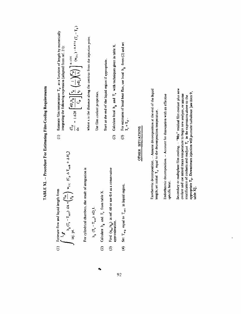
IllE
.=_.
0
E
L.0
f,,r,,
oli=
I
X
,-,1
i.=,
>, I-,
.o _
<1-#-
<_
E
V
o ,_.. ....-,
<,i
o
o
E
....-1
I
I_, "llt,o C> ="
<-. _0 t,'.' _i
<'.a _<"a
c
F--
o
_ _ _<,,
_ _ _'_o._ _ o= <<,-_
ei. $ eo==.
'<*" I <.> ;_'
oE .__x
_'- "E _ °'_. °E_ _= _ -• r _

small quantities of film coolant are required, it is recommended that no less flow be used
than that controlled by 0.015-in. (0.381 ram) diameter orifices spaced 0.3 in. (7.62 ram)
apart.
It is recommended that optimum film cooling be considered in cases of well-defined heating
patterns and demands for maximum performance. Tailor the circumferential distribution offi|m cooling to concentrate the coolant at hot streaks where it is needed, and minimizecoolant in the cool streaks. This tailoring can be accomplished only after an experimental
evaluation has been made of the injector heating pattern.
3.4 Coatings
3.4.1 Spalling Without Failure
Localized spalling of the insulation coating in a chamber shah not result in
chamber failure.
When calculating bulk temperature rises, include in the thermal model any coatings that are
applied intentionally for insulation or that develop inherently as deposits from the
reactants; references 61 and 62 provide information on carbon formation. However, local
cooling at all stations within the coated area must be sufficient even in the absence of the
coating.
Use a base metal that is compatible with the combustion products so that, if the coating
spalls, the base metal will not be chemically attacked.
3.4.2 Coating Strength
Protective coatings shall withstand transient conditions, states of residual heat,
injector streaking, and repair operations.
Coatings that will withstand thermal shock without fracture can be obtained by using verythin gradated coatings 0.004 to 0.010 in. (0.102 to 0.254 mm) thick, preferably composed
of materials containing a metal additive. In addition, the nature of the environment must be
evaluated during transient operation, when oxidizer-rich mixtures and streaking can exist;
the coating must be compatible with these transient conditions. The result may involve the
use of a surface coating that represents a compromise from that desired for steady-state
operation.
The residual heat within the coating at shutdown must be dissipated without damage to the
coating or the chamber. Residual heat appears to be a particular problem in thick coatings.
93

The extent of this problemis not known,althoughsomeanalysesindicatethat potentialhazardsexist.The following procedures are recommended: (1) determine if melting of the
base metal from the residual heat at shutdown is a possibility without postfire cooling; ifmelting is possible, consider supplemental cooling operations; (2) if a detonable coolant is
used, estimate the bulk temperatures to see if detonation can occur; and (3) if oxidizer is
used as a coolant, consider the problem of compatibility between the hot coating and anoxidizing atmosphere in the combustion chamber after shutdown.
Anticipate local spalling of protective coatings and establish repair criteria and procedures.
Use fairly heavy and rigid surfaces to minimize motion of the coated surfaces during
operation to reduce spalling. Heavy flanges and rings are more adaptable to protection by
coatings than are flexible coolant tubes or thin cooled walls. Further, heavy surfaces areamenable to grit blasting to provide roughened surfaces for stronger bonding.
Unfortunately, repair is an ill-defined area. Some suggestions, however, are to (1) permit
small amounts of spalling, (2) recoat by local application of the top-coat if it is gradated, (3)
avoid putting on too thick a repair coating, and (4) if feasible, remove all the old coatingand recoat.
94

REFERENCES
1. Lary, F. B.: Advanced Cryogenic Rocket Engine Program, Aerospike Nozzle Concept (U). Rep.NAA-R R-7168, Rocketdyne Div., North American Rockwell Corp., Jan. 1968. (Confidential)
2. Gakle, P. S.; Sjogren, R. G.; Van Huff, N. E.; Williams, R. J.; and Tomlinson, E. M.: Improved Titan
Predevelopment (U). Rep. AGC 212 FR-65, Aerojet-General Corp., Feb. 1966. (Confidential)
3. Anon.: Advanced Rocket Engine - Storable (U). Rep. AGC R-10830-F-1, Aerojet-General Corp.,
May 1968. (Confidential)
4. Anon.: Investigation of Light Hydrocarbon Fuels With FLOX Mixtures as Liquid Rocket Propellants.
Rep. PWA FR-1443, Pratt and Whitney Aircraft Div. of United Aircraft (W. Palm Beach, FL), Sept. 1,
1965.
5. Anon.: Space Storable Regenerative Cooling Investigation. Rep. PWA FR-2552, Pratt and WhitneyAircraft Div. of United Aircraft (W. Palm Beach, FL), July 26, 1968.
6. Pauckert, R. P.: Space Storable Regenerative Cooling Investigation. Rep. NAA-R R-7338,
Rocketdyne Div., North American Rockwell Corp., Sept. 25, 1968.
. Anon.: Investigation of Light Hydrocarbon Fuels with Fluorine-Oxygen Mixtures as Liquid Rocket
Propellants. Rep. PWA FR-2227, Pratt and Whitney Aircraft Div. of United Aircraft (W. Palm Beach,
FL), Sept. 15, 1967.
8. Goalwin, D. S.: A High Pressure, Regeneratively Cooled Thrust Chamber (U). CPIA Publ. 176, vol. II,
CPIA, Oct. 1968, pp. 375-398. (Confidential)
9. Fialkoff, S.; Mark, R.; Webb, M.; and Glassman, I.: Fabrication, Structural and Heat TransferConsiderations of Electroformed Rocket Nozzles. Liquid Rockets and Propellants, Vol. 2 of Progress
in Astronautics and Rocketry, Div. F, edited by L. E. Bollinger, M. Goldsmith, and A. W. Lemmon,
Jr., Academic Press (New York and London), 1960, pp. 563-588.
10. Fulton, D. L.: Investigation of Non-Tubular-Wall Regeneratively Cooled Thrust Chamber Concepts
(I5). Rep. NAA-R R-7910, Rocketdyne Div., North American Rockewll Corp., Dec. 1969.
(Confidential)
11. Atherton, R. R.: Air Force Reusable Rocket Engine Program. Rep. PWA FR-3832, Pratt and WhitneyAircraft Div. of United Aircraft (W. Palm Beach, FL), Jan. 1971.
12. Safeer, N. I., ed.: Liquid Propellant Engine Manual (U). CPIA Publ. M5, CPIA, Dec. 1967.
(Confidential)
13. Anon.: Monthly and Quarterly Progress Reports for NERVA Program (U). Aerojet-General Corp.,
Contract SNP-1, 1962-1970. (Confidential)
95

14.Munk,W.R.;etal.:ResearchonaHydrogen-FluorinePropulsionSystem(U).Rep.PWAFR-1585,Prattand WhitneyAircraftDiv. of UnitedAircraft(W. PalmBeach,FL), Oct.21, 1966.(Confidential)
15.Anon.:AdvancedManeuveringPropulsionTechnologyProgram.Vol.1- Fluorine/HydrogenEngineSystemAnalysisandDesign(U).RocketdyneDiv.,NorthAmericanRockwellCorp.,Nov.1970.(Confidential)
16.
"17.
Anon.:MA-5 FLOXSustainerEngineFeasibilityTestProgram(U). Rep.NAA-RR-6363,RocketdyneDiv.,NorthAmericanRockwellCorp.,Feb.28,1966.(Confidential)
Anon.:AerojetModelAJ10-104RocketPropulsionSystem.Rep.AGCR-1958,Aerojet-GeneralCorp.,May1961.
18.Anon.:ResearchandDevelopmentof theE-1RocketEngine.Rep.R-687P,RocketdyneDiv.,NorthAmericanRockwellCorp.,Feb.12,1958.
19.Curren,A.N.;Price,H.G.;Krueger,R.C.;andManning,L.C.:ExperimentalHeatTransferStudyofa RegenerativelyCooledHydrogen-FluorineRocketEngineat LowChamberPressure.NASATND-4178,1967.
20.
21.
Bartz,D.R.:A SimpleEquationforRapidEstimationof RocketNozzleConvectiveHeatTransferCoefficients.JetPropulsion,vol.27,1957,pp.49-51.
Hatch,J.E.;andPapell,S.S.:Useof aTheoreticalFlowModelToCorrelateDataforFilmCoolingorHeatinganAdiabaticWallbyTangentialInjectionof Gasesof DifferentFluidProperties.NASATND-130,Nov.1959.
22. Taylor,M.F.: Correlationof LocalHeatTransferCoefficientsforSingle-PhaseTurbulent Flow of
Hydrogen in Tubes With Temperature Ratios to 23. NASA TN D-4332, 1968. (Also see J. SpacecraftRockets, vol. 5, no. 11, Nov. 1968, pp.1353 - 1355.)
23. Anon.: Metallic Materials and Elements for Aerospace Vehicle Structures. Dept. of Defense MilitaryHandbook MIL-HDBK-5. MIL-HDBK-5A, Change Notice 3, Dec. 1968.
24. Smith, K. J.; et al.: Feasibility Demonstration of a Transpiration Cooled Nozzle System (U). Rep.TRW ER-5209-F, TRW Inc., Mar. 1966. (Confidential)
25. Ahem, J. E.; et al.: Evaluation of Spiral Wound Ribbon Structures for Transpiration/Film Cooling(I3). Rep. Marquardt 25,230, Marquardt Corp., Jan. 1968. (Confidential)
26. Anon.: High Pressure Rocket Engine Feasibility Program (I3). Rep. PWA FR-1171, Pratt and WhitneyAircraft Div. of United Aircraft (W. Palm Beach, FL), Dec. 10, 1964. (Confidential)
27. Anon.: High Chamber Pressure Staged Combustion Research Program (U). Rep. PWA FR-1676, Pratt
and Whitney Aircraft Div. of United Aircraft (W. Palm Beach, FL), June 30, 1966. (Confidential)
*Dossier for design criteria monograph "Liquid Rocket Engine Fluid-Cooled Combustion Chambers." Unpublished, 1969.Collected source material available for inspection at NASA Lewis Research Center, Cleveland, Ohio.
96
28.Atherton,R.R.:Applicationsfor aHighPerformanceCryogenicStagedCombustionRocketEngine(U).Rep.PWAFR-2471,PrattandWhitneyAircraftDiv.of UnitedAircraft(W.PalmBeach,FL),Nov.1967.(Confidential)
29. Anon.:StudyandDemonstrationof anAdvancedThrust Chamber Cooling Concept (Project
Transpire) (U). Rep. FR-67-4, Aerojet-General Corp., Oct. 1967. (Confidential)
30. Pompa, M. F.: Thrust Chamber Assembly Design and Development for Able Propulsion Systems.
Paper presented at 15th Annual Meeting, American Rocket Society (Washington, DC), Dec. 1960.
Schindler, R. C.: Personal Communication. Aerojet-General Corp., July 1968.
Harrington, D. C.; and Peterson, L. E.: Thermal Barrier Liners for Regeneratively Cooled Rocket
Engine Combustion Chambers (U). Rep. AGC R-212/SA3-F, Aerojet-General Corp., Nov. 20, 1964.
(Confidential)
33. Stubbs, V. R.: Investigation of Advanced Regenerative Thrust Chamber Designs. NASA CR-72742,
Aerojet-General Corp., Nov. 15, 1970.
34. Van Huff, N. E.; and Rousar, D. C.: Ultimate Heat Flux Limits of Storable Propellants (U). 8th
Liquid Propulsion Symposium (U) (Cleveland, Ohio), Nov. 7-9, 1966, CPIA Publ. 121, vol. !1, Oct.
1966, pp. 227-276. (Confidential)
35. Rothbart, H. A., ed.: Mechanical Systems and Design Handbook. McGraw-Hill Book Co., Inc., 1964,
p. 15 - 16
36. Baker, E. H.; Caprilli, A. P.; Kovacevsky, L.; Rish, R. L.; and Verette, R. M.: Shell Analysis Manual.
NASA CR-912, Apr. 1968.
37. Harvey, J. F.: Pressure Vessel Design. D. Van Nostrand Co., Inc., 1963.
38. Langer, B. F.: Design of Pressure Vessels for Low-Cycle Fatigue. J. Basic Eng., Trans. ASME, Series
D, vol. 84, 1962, pp. 389-402.
39. Coffin, L. F.: Thermal Stress Fatigue. Prod. Eng., vol. 28, no. 6, June 1957, pp. 175-179.
40. Manson, S. S.: Thermal Stresses in Design, Part 3 - Basic Concepts of Fatigue in Ductile Materials.
Mach. Des., vol. 30, no. 16, Aug. 7, 1958, pp. 100-107.
41. Benham, P. P.; and Hoyle, R.: Thermal Stress. Sir Isaac Pitman & Sons, Ltd. (London), 1964.
42. Avery, L. R.; Carayanis, G. S.; and Kichky, G. L.: Thermal-Fatigue Tests of RestrainedCombustor-Cooling Tubes. Experimental Mechanics, J. SESA, vol. 7, no. 6, June 1967, pp. 256-264.
43. Kuyper, D. J.; and Burge, H. L.: Simplified Thermal Fatigue Analysis for Liquid Rocket Combustion
Chambers. J. Spacecraft Rockets, vol. 4, no. 1, Jan. 1967, pp. 126-128.
*Dossier for design criteria monograph "Liquid Rocket Engine Fluid-Cooled C_mbustion Chambers." Unpublished, 1969.Collected source material available for inspection at NASA Lewis Research Center, Cleveland, Ohio.
97
44. Manson,S.S.:ThermalStressandLow-CycleFatigue. McGraw-Hill Book Co., Inc., 1966.i
45. Murray, R. L.: PHOEBUS-2 Materials Final Report. Rep. AGC RP-SR-0002, App. E, Aerojet-GeneralCorp., Sept. 1967.
46. Manson, S. S.; and Halford, G.: A Method of Estimating High Temperature Low Cycle FatigueBehavior of Metals. NASA TM X-52270, June 1967.
47. Almroth, B. O.; and Bushnell, D.: Computer Analysis of Various Shells of Revolution. AIAA J., vol.6, no. I0, Oct. 1968, pp. 1848-1855.
48. Bushnell, D.; Almroth, B.; and Subel, L.: Buckling of Shells of Revolution With Various Wall
Constructions. NASA CR-1050, May 1968.
49. Dong, S. B.: Analysis of Laminated Shells of Revolution. J. Eng. Mechanics Div., Proc. ASCE, vol. 92,no. EM6, Dec. 1966.
50. Flugge, W.: Stresses in Shells. Springer-Verlag (Berlin), 1960.
51. Kraus, H.: Thin Elastic Shells. John Wiley & Sons, Inc., 1967.
52. Timoshenko, S.; and Woinowsky-Krieger, S.: Theory of Plates and Shells. Second ed., McGraw-HillBook Co., Inc., 1959.
53. Zienkiewicz, O. C.: The Finite Element Method in Structural and Continuum Mechanics.
McGraw-Hill Pub. Co. Ltd. (London), 1967.
54. Schaeffer, H. G.: Computer Program for Finite-Difference Solutions of Shells of Revolution Under
Asymmetric Loads. NASA TN D-3926, May 1967.
55. Percy, J. H.; Navaratna, D. R.; and Klein, S.: Sabor III, A Fortran Program for the Linear Elastic
Analysis of Thin Shells of Revolution Under Asymmetric or Axisymmetric Loading Using the Matrix
DisPlacement Method. Rep. ASRL-TR-121-6 (AD 617308), Aeroelastic and Structures Research Lab,Mass. Inst. Tech., May 1965
56. Ross, B.; Mayers, J.; and Jaworski, A.: Buckling of Thin Cylindrical Shells Heated Along an AxialStrip. Experimental Mechanics, J. SESA, vol. 5, no. 8, Aug. 1965, pp. 247-256.
57. Hoff, J. H.; and Ross, B.: A New Solution of the Buckling Problem of Thin Circular Cylindrical Shells
Heated Along an Axial Strip. Recent Progress in Applied Mechanics, John Wiley & Sons, Inc., 1967.
58. Blubaugh, A. L.; and Zisk, E. J.: Demonstration of an Advanced Transpiration Cooled Thrust
Chamber (U). Rep. AGC 10922 FR-66-10, Aerojet-General Corp., Mar. 1967. (Confidential).
59. Rannie, W. D.: A Simplified Theory of Porous Wall Cooling. Rep. PR-4-50, Calif. Inst. of Tech., Nov.24, 1947.
60. Anon.: High Energy Propellant Beryllium Thrust Chamber Program (U). Rep. AFRPL-TR-48-1, vol.
II, Rocketdyne Div., North American Rockwell Corp., Jan. 1968. (Confidential)
98

61. Sellers, J. P.: Effect of Carbon Deposition on Heat Transfer in a LOX/RP-I Thrust Chamber. ARS J.,
vol. 31, no. 5, May 1961, pp. 662-663.
62. Anon.: Final Report - Investigation of Light Hydrocarbon Fuels. NASA CR-54445, Sept. 1965.
99


Term or symbol
A
bifurcation joint
boundary-layer trip
c*
Cg
Cp
Charpy test
coking
contraction ratio
D
e
E
F
Fty
AHv
h
hat
k
GLOSSARY'
Definition
area, in. 2 or ft 2 (m2) '
junction of two tubes or passages with one larger tube or passage
discontinuity or local turbulence in the boundary layer generated by a
protrusion from the surface in contact with the boundary layer;
trippingusually increases the severity of the thermal environment
characteristic exhaust velocity, ft/sec (m/sec)
heat-transfer correlation constant
specific heat at constant pressure, BTU/lbm-°R (J/kg-K)
a test for impact strength in which a notched bar (of specified
dimensions) is struck by a swinging pendulum, and the energy absorbedin the fracture is measured. A striking velocity of 17.5 ft/sec (5.33
m/sec) is employed; test values are given in lb-ft (N-m).
developing a residue when burned or distilled
ratio of the area of the chamber at its maximum diameter to the area of
the throat
diameter, in. or ft (m)
fracture elongation, in./in. (m/m)
Young's modulus, psi (N/m 2)
thrust, lbf (N)
0.2% offset yield strength, psi (N/m 2)
heat of vaporization, BTU/lbm (J/kg)
convective heat transfer coefficient, BTU/in 2 -sec-°F (J/m 2 -sec-K)
descriptive term for a flanged, square-bottom "U" cross section
thermal conductivity, BTU/hr-ft-°F (J/hr-m-K)
'Parenthetical units here and in the text are in the International System of Units (SI units). See Mechtly, E.A.: The
International System of Units. Physical Constants and Conversion Factors, Revised. NASA SP-7012, 1969.
101

Term or symbol
L
L*
L_
MEOP
MS
N
P
Pr
R
r
Re
solidus temperature
St
T
tripping
U
V
V
W
Ot
A
eff
Et
r/g
r/m
Definition
length, in. or ft (m)
characteristic chamber length, L* = Vc/A t
chamber length to be film cooled, in. or ft (m)
maximum expected operating pressure, psi (N/m 2)
margin of safety
average cyclic life, cycles
pressure, psia (N/m 2)
Prandtl number,/_ Cp/k
ratio of the design load (or stress) to the allowable load (or stress)
ratio of allowable tensile to compressive strengths
Reynolds number, pu Dc//a
temperature at which melting starts
Stanton number, hg/pu Cp
temperature, °R or °F (K)
see "boundary layer trip"
velocity at edge of boundary layer, ft/sec (m/see)
volume, ft a or in. 3 (m 3)
velocity, ft/sec (m/see)
flowrate, lbm/sec (kg/sec)
coefficient of thermal expansion, in./in.-°F (m/m-K)
difference or change in a quantity
calculated effective cyclic strain, in./in. (m/m)
allowable cyclic strain, in./in. (m/m)
lag enhancement factor
mixing loss factor
102

Term or symbol
P
o
T
Subscripts
act
B
c
crit
eft
F
FC
FS
g
o
r
sat
sub
th
t
wg
w_
x,y,z
Definition
viscosity, lbm/ft-sec (N-sec/m 2)
heat flux, BTU/in. 2 -sec (J/m 2 -sec)
density, lbm/ft 3 (kg/m 3)
direct stress, psi (N/m 2)
shear stress, psi (N/m 2)
actual
bulk
chamber
critical
effective
film
film coolant
freestream
gas-side
liquid
stagnation
recovery
saturation
subcooling
theoretical
nozzle throat
gas-side wall
liquid-side wall
rectangular Cartesian coordinates
103

Material
(designation in monograph)
A-50, Aerozine-50
Alumizine
CRES
CTF
DECH
DETA
EDA
FLOX
Freon
GH2
Hastelloy X,N
Inconel X, 718
IRFNA
LF2
LH2
LOX
t2n3
MHF-3, 5
MMH
Nickel A; Nickel 200
Identification
50/50 blend of hydrazine and UDMH
proprietary blend of hydrazine, aluminum powder, and gelling agent
corrosion resistant steel
chlorine trifluoride
diethylcyclohexane
diethylenetriamine
ethylenediamine
mixture of LF2 and LOX
E. I. Dupont Co. trademark for a family of fluorinated hydrocarbons
gaseous hydrogen
Haynes-Stellite Corp. designations for nickel-base high-temperaturealloys
International Nickel Co. designations for nickel-chromium alloys
inhibited red fuming nitric acid
liquid fluorine
liquid hydrogen
liquid oxygen
liquefied petroleum gas
mixed hydrazine fuels
monome thylhydrazine
International Nickel Co. designation for commercially pure nickel
104

Material
Nickel 270
Nicobraz cement
Rigimesh
Rokide
R235
Teflon
TD nickel
UDMH
Waspaloy
WFNA
6061-T6
304
316
321
347
29-20 SS
4130
5052
Identification
International Nickel Co. designation for high-purity nickel
a proprietary acrylic resin binder for braze alloy powders; product of
Wall Colmony Corp. (Detroit, MI)
trademark of Aircraft Porous Media, Inc. (Glen Cove, NY) for porous
plate formed by compressed, sintered stacks of wire screen
trademark of The Carborundum Co. (Niagara Falls, NY) for flame-
sprayed coating, usually zirconia or alumina
General Motors Corp. designation for an agehardenable nickel-base
casting alloy
E. I. Dupont Co. designation for tetrafluoroethyene fluorocarbon resins
E. I. Dupont Co. designation for a nickel strengthened by dispersions ofthoria
unsymmetrical dimethylhydrazine
Pratt & Whitney Aircraft designation for a nickel-base,
high-temperature super alloy
white fuming nitric acid
Aluminum Association designation for a heat-treated, wrought
aluminum alloy
AISI designation for a low-carbon, austenitic stainless steel
AISI designation for a high-temperature, nonstabilized stainless steel
AISI designation for a titanium-stabilized, austenitic stainless steel
AISI designation for a columbium-stabilized, austenitic stainless steel
Carpenter Steel Co. designation for a stabilized, austenitic stainless steel
SAE designation for low-alloy carbon steel
non-heat-treatable aluminum alloy
105

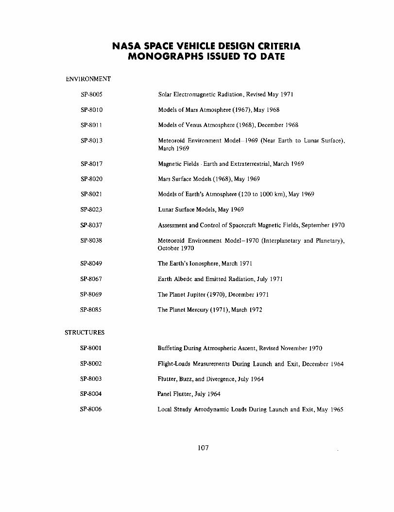
NASA SPACE VEHICLE DESIGN CRITERIAMONOGRAPHS ISSUED TO DATE
ENVIRONMENT
SP-8005
SP-8010
SP-8011
SP-8013
SP-8017
SP-8020
SP-8021
SP-8023
SP-8037
SP-8038
SP-8049
SP-8067
SP-8069
SP-8085
Solar Electromagnetic Radiation, Revised May 1971
Models of Mars Atmosphere (1967), May 1968
Models of Venus Atmosphere (1968), December 1968
Meteoroid Environment Model-1969 (Near Earth to Lunar Surface),March 1969
Magnetic Fields-Earth and Extraterrestrial, March 1969
Mars Surface Models (1968), May 1969
Models of Earth's Atmosphere (120 to 1000 km), May 1969
Lunar Surface Models, May 1969
Assessment and Control of Spacecraft Magnetic Fields, September 1970
Meteoroid Environment Model-1970 (Interplanetary and Planetary),October 1970
The Earth's Ionosphere, March 1971
Earth Albedc and Emitted Radiation, July 1971
The Planet Jupiter (1970), December 1971
The Planet Mercury (1971), March 1972
STRUCTURES
SP-8001
SP-8002
SP-8003
SP-8004
SP-8006
Buffeting During Atmospheric Ascent, Revised November 1970
Flight-Loads Measurements During Launch and Exit, December 1964
Flutter, Buzz, and Divergence, July 1964
Panel Flutter, July 1964
Local Steady Aerodynamic Loads During Launch and Exit, May 1965
107

SP-8007
SP-8008
SP-8009
SP-8012
SP-8014
SP-8019
SP-8022
SP-8029
SP-8030
SP-8031
SP-8032
SP-8035
SP-8040
SP-8042
SP-8043
SP-8044
SP-8045
SP-8046
SP-8050
SP-8053
SP-8054
SP-8055
SP-8056
BucklingofThin-WalledCircularCylinders,RevisedAugust1968
PrelaunchGroundWindLoads,November1965
PropellantSloshLoads,August1968
NaturalVibrationModalAnalysis,September1968
EntryThermalProtection,August1968
BucklingofThin-WalledTruncatedCones,September1968
StagingLoads,February1969
AerodynamicandRocket-ExhaustHeatingDuringLaunchandAscentMay1969
TransientLoadsFromThrust Excitation, February 1969
Slosh Suppression, May 1969
Buckling of Thin-Walled Doubly Curved Shells, August 1969
Wind Loads During Ascent, June 1970
Fracture Control of Metallic Pressure Vessels, May 1970
Meteoroid Damage Assessment, May 1970
Design-Development Testing, May 1970
Qualification Testing, May 1970
Acceptance Testing, April 1970
Landing Impact Attenuation for Non-Surface-Planing Landers, April1970
Structural Vibration Prediction, June 1970
Nuclear and Space Radiation Effects on Materials, June 1970
Space Radiation Protection, June 1970
Prevention of Coupled Structure-Propulsion Instability (Pogo), October1970
Flight Separation Mechanisms, October 1970
108
SP-8057
SP-8060
SP-8061
SP-8062
SP-8063
SP-8066
SP-8068
SP-8072
SP-8077
SP-8079
SP-8082
SP-8083
SP-8095
GUIDANCE AND CONTROL
SP-8015
SP-8016
SP-8018
SP-8024
SP-8026
SP-8027
SP-8028
SP-8033
SP-8034
Structural Design Criteria Applicable to a Space Shuttle, January 1971
Compartment Venting, November 1970
Interaction with Umbilicals and Launch Stand, August 1970
Entry Gasdynarnic Heating, January 1971
Lubrication, Friction, and Wear, June 1971
Deployable Aerodynamic Deceleration Systems, June 1971
Buckling Strength of Structural Plates, June 1971
Acoustic Loads Generated by the Propulsion System, June 1971
Transportation and Handling Loads, September 1971
Structural Interaction with Control Systems, November 1971
Stress-Corrosion Cracking in Metals, August 1971
Discontinuity Stresses in Metallic Pressure Vessels, November 1971
Preliminary Criteria for the Fracture Control of Space Shuttle
Structures, June 1971
Guidance and Navigation for Entry Vehicles, November 1968
Effects of Structural Flexibility on Spacecraft Control Systems, April1969
Spacecraft Magnetic Torques, March 1969
Spacecraft Gravitational Torques, May 1969
Spacecraft Star Trackers, July 1970
Spacecraft Radiation Torques, October 1969
Entry Vehicle Control, November 1969
Spacecraft Earth Horizon Sensors, December 1969
Spacecraft Mass Expulsion Torques, December 1969
109

SP-8036
SP-8047
SP-8058
SP-8059
SP-8065
SP-8070
SP-8071
SP-8074
SP-8078
SP-8086
CHEMICALPROPULSION
SP-8081
SP-8052
SP-8048
SP-8064
SP-8075
SP-8076
SP-8039
SP-8051
SP-8025
SP-8041
Effectsof StructuralFlexibilityonLaunchVehicleControlSystems,February1970
SpacecraftSunSensors,June1970
SpacecraftAerodynamicTorques, January 1971
Spacecraft Attitude Control During Thrusting Maneuvers, February1971
Tubular Spacecraft Booms (Extendible, Reel Stored), February 1971
Spaceborne Digital Computer Systems, March 1971
Passive Gravity-Gradient Libration Dampers, February 1971
Spacecraft Solar Cell Arrays, May 1971
Spaceborne Electronic Imaging Systems, June 1971
Space Vehicle Displays Design Criteria, March 1972
Liquid Propellant Gas Generators, March 1972
Liquid Rocket Engine Turbopump Inducers, May 1971
Liquid Rocket Engine Turbopump Bearings, March 1971
Solid Propellant Selection and Characterization, June 1971
Solid Propellant Processing Factors in Rocket Motor Design, October1971
Solid Propellant Grain Design and Internal Ballistics, March 1972
Solid Rocket Motor Performance Analysis and Prediction, May 1971
Solid Rocket Motor Igniters, March 1971
Solid Rocket Motor Metal Cases, April 1970
Captive-Fired Testing of Solid Rocket Motors, March 1971
1 I (_ ¢,U,S. GOVERNMENT PRINTING OFFICE: 1973-739-151/16


![Rocket! :]](https://img.pdfslide.us/doc/110x75/558c01cdd8b42abd5b8b4570/rocket-.jpg)