Embed Size (px)
Citation preview

LIQUID RING PUMPSeries 3 Design
INSTALLATION, OPERATION
AND
MAINTENANCE MANUAL
Graham Corporation20 Florence Avenue
Batavia, New York 14020(716) 343-2216, Fax (716) 343-1097
e-mail: [email protected]
IOM-LRP3-999
Vacuum and Heat Transfer

Graham Corporation
2
Table of Contents
Section 1 - General Information...................................................................31.1 Introduction.......................................................................................................................31.2 General Description and Principle of Operation.............................................................41.3 Description of Pump Model Codes..................................................................................5
Section 2 - Installation Instructions .............................................................62.1 Handling............................................................................................................................62.2 Preservation......................................................................................................................62.3 Mounting...........................................................................................................................62.4 Installation........................................................................................................................62.5 Coupling Alignment ..........................................................................................................72.6 Belt Drives........................................................................................................................82.7 Service Liquid Piping Arrangements ...............................................................................82.8 Shaft Seal Coolant ..........................................................................................................112.9 Piping Requirements ......................................................................................................112.10 Electrical Requirements...............................................................................................12
Section 3 - Operating Instructions .............................................................133.1 Start-up Procedures........................................................................................................133.2 Service Liquid Requirements ........................................................................................133.3 Cavitation........................................................................................................................143.4 Shut-Down Procedures...................................................................................................15
Section 4 - Accessory Items........................................................................164.1 Accessories.....................................................................................................................16
Section 5 - Maintenance.............................................................................185.1 Performance....................................................................................................................185.2 Series 3 Pump Estimated Weights (lbs.)* .....................................................................185.3 Shaft Bearings ................................................................................................................195.4 Mechanical Seals ...........................................................................................................195.5 Storage ............................................................................................................................195.6 Removal from storage....................................................................................................205.7 Troubleshooting Chart ...................................................................................................21
Section 6 - Disassembly And Reassembly Procedures ..............................226.1 General ...........................................................................................................................226.2 Impeller End Clearances................................................................................................226.3 Tie Rod Torque Values..................................................................................................246.4 Bearing Data ..................................................................................................................24
Section 7 - Warranty ..................................................................................25Appendix A - Material Safety Data Sheet..................................................26Appendix B - Return Material Authorization Form...................................30

Graham Corporation
3
Section 1 - General Information
1.1 Introduction
This manual will provide assistance in the set-up, operation, and maintenance of your Graham LiquidRing Pump. Please read this manual completely prior to operating your Liquid Ring Pump. If you needto contact the Pump Service department for assistance, please have available the pump serial number,model number, and ID number if possible. The ID number is stamped on the edge of the dischargeflange. The Pump Service department may be reached by contacting Graham Corporation in Batavia,NY by phone (716) 343-2216, Fax (716) 343-1097, or e-mail at [email protected].
Graham has an extensive stock of spare parts and replacement pumps. Stocked parts and pumps canbe shipped from our warehouse in Batavia, NY, by a carrier of your choice.
For your convenience, use our toll free number ( 1-800-828-8150 ) only when ordering spare partsand replacement pumps. Please have the model number, serial number and part number of the itemsrequired when placing an order. Normal business hours are 8:00 a.m. to 5:00 p.m. (E.S.T.), Mondaythrough Friday.
Factory rebuilding service is available for pumps returned to Batavia. When a pump is returned to thefactory for repairs, please drain and flush the pump and include a Material Safety Data Sheet (MSDS)for the process in which the pump was used. A Return Material Authorization (RMA) Number,issued by Graham, is required before returning a pump. A sample form is included at the back of thismanual to show what type of information is required to obtain an RMA Number. Field ServiceTechnicians are also available for travel to the jobsite for troubleshooting and repair or rebuilding ofpumps.
This document and the information contained herein are the property of Graham Corporation and mustnot be copied, in whole or in part, nor used for manufacture or otherwise disclosed without the priorwritten consent of the company. Information contained herein may, from time to time, be revisedand/or updated. Copyright Graham Corporation 1999

Graham Corporation
4
1.2 General Description and Principle of Operation
Graham Vacuum Pumps and Compressors are of the liquid ring type. Single and two stage pumps areavailable in a wide range of sizes and materials. These options are listed in the Graham Sales Bulletins.The major component of the Graham pump is a multi-bladed rotating assembly positionedeccentrically in a cylindrical casing. (See Figure 1) This assembly is driven by an external source,normally an electric motor. Service liquid (usually water) is introduced into the pump. As the impellerrotates, centrifugal force creates a liquid ring which is concentric to the casing. At the inlet, the areabetween the impeller blades (buckets) increase in size, drawing gas in. As the impeller continues torotate toward the discharge, the impeller bucket area decreases in size, compressing the gas. Thisgas, along with the liquid from the pump, is discharged through the outlet nozzle. The service liquid isseparated from the gas and cooled for reuse in the pump or sent to a drain. In addition to being thecompressing medium, the liquid ring performs two other important functions:
1) It absorbs the heat generated by compression, friction, and condensation of theincoming vapor.
2) It absorbs and washes out any process contaminants entrained in the gas.
A continuous supply of service liquid is necessary to limit the temperature rise in the pump caused bythe heat of compression, friction, and condensation. Any excessive rise in temperature will have adetrimental effect on performance, reducing the capacity and degree of vacuum attainable. Installationschematics for the supply of the service liquid and for the separation of the gas and liquid dischargedfrom the pump are shown in Section 2.
Figure 1
Shaft
Suction Port
Impeller
Gas
Discharge Port
Liquid Ring
Gas andLiquid Outlet
Gas Inlet
Rotation

Graham Corporation
5
Service liquid quantities are a function of the particular model and the intended application. Check thedata sheet for your specific pump model or see Table 1 of Section 3 which lists typical service liquidrequirements.
The normal operating ranges of Liquid Ring Pumps when using water at 59º F(15 ºC) for the service liquid are:
Single Stage Pumps down to 150 mmHgATwo Stage Pumps down to 25 mmHgATwo Stage Pumps w/Air Ejector down to 3 mmHgASingle Stage Compressors 20 psi (1.4 bar) max. differentialTwo Stage Compressors 30 psi (2.1 bar) max. differential
The standard materials of construction are suitable for handling air and other non-corrosive gases,while using water as the service liquid. Other materials can be supplied for special applications.
1.3 Description of Pump Model Codes
Each pump is designated by a model code which describes the materials of construction, size, type ofshaft seals, and any special features. An example of a typical pump is shown below. Contact Grahamfor a complete listing of the codes used to describe the pump.
Number of Stages
Frame Size
Pump Series
Impeller Size
Shaft Seal Code
Special Features
3 PV 42120 / 12 / 43 / M / NF
Connectionand ShaftEnd Type
PumpMaterialCode
Vacuum Pump = PVCompressor = PC

Graham Corporation
6
Section 2 - Installation Instructions
2.1 Handling
Carefully unpack the pump. Bare pumps may be lifted with a sling placed around the bearing housingsor under the flanges.
Place slings around the motor and the pump for units supplied with C-Face motors attached.
For baseplate mounted units, lift the pump-motor assemblies by the baseplate only. Do not attachslings nor hooks to the motor or the pump as this can cause misalignment. Do not attempt to run thepump until the installation work is complete.
CAUTION: DO NOT RUN THE PUMP WITHOUT SERVICE LIQUID AND SHAFTSEAL FLUID.
2.2 Preservation
Cast Iron pumps are protected internally with a preservative solution applied at the factory beforeshipping. The solution should be flushed from the pump prior to use. An MSDS form is included inthe back of this manual.
The preservative solution is petroleum based and must be disposed ofin accordance with all Local, State, and Federal regulations.
2.3 Mounting
Before operation, the pump package should be carefully set, leveled, and securely bolted in place. Itis recommended that shims and grout be used as necessary under all structural members of the base.
The Series 3 pumps are supplied as a standard to accept an adapter for mounting a NEMA C-Facemotor. The pump and support bracket (adapter) should be bolted to the floor, a cement pad, orexisting framework. Level and shim as required.
If baseplates are supplied with a pump and drive motor mounted at the factory, then they should beleveled, shimmed as required, and firmly anchored.
2.4 Installation
All piping to the pump should be adequately supported to eliminate any stress at the pumpconnections. All piping joints should be tested for leaks prior to start-up. A temporary start-up strainerin the process inlet piping may be used to keep large contaminates from entering the pump at start-up.

Graham Corporation
7
The location of the installation or the storage of the pump should be in an area that willnot subject the pump to freezing.
Verify the pump’s rotation direction by checking the arrow on the shaft end casing. Refer to section2.10 concerning the electrical requirements.
2.5 Coupling Alignment
CAUTION: TO PREVENT PERSONAL INJURY, DO NOT OPERATE THE PUMPWITHOUT PROPERLY GUARDING THE DRIVE COUPLING.
The Series 3 pumps utilize precise machining of the pump drive end bearing housing, motor adapter,and C-Face motor flange to eliminate shaft misalignment. The coupling should be inspected beforestart-up.
Baseplate mounted pumps and motors supplied from the factory have had the shafts aligned prior toshipment. This ensures that alignment can be done in the field. It is required that the shaft alignmentbe rechecked after mounting on a level foundation and prior to start-up.
For smoother operation and longer life of the coupled equipment, the following maximum misalignmenttolerances are recommended for baseplate mounted units:
The maximum allowable parallel shaft misalignment is ±0.002" (0.05 mm).
The maximum allowable angular shaft misalignment is ±0.0005" per inch(0.013 per mm) of coupling diameter.
±0.002"
D
±0.0005" x D

Graham Corporation
8
2.6 Belt Drives
CAUTION: TO PREVENT PERSONAL INJURY, DO NOT OPERATE THEPUMP WITHOUT PROPERLY GUARDING THE DRIVE BELTS.
When pumps are supplied with belt drives, follow the belt manufacturer’s instructions to set the tension.
2.7 Service Liquid Piping Arrangements
The operating principle of a liquid ring pump depends on a continuous supply of clean service liquid,which is normally water. The liquid enters the pump through a connection on the casing and isdischarged from the pump along with the gas. There are two basic piping arrangements that can beused for liquid ring pump applications. A once-through method with no recovery of the service liquidand a recirculation method which re-uses the service liquid.
Both of these arrangements have four basic elements:
1) A supply of service liquid.2) A means to control flow of service liquid.3) A means of stopping the flow of service liquid when the pump is off.4) A means of separating the gas / liquid exhaust mixture.
It is recommended to use a strainer to ensure that foreign matter does not enter the pump with theservice liquid supply or make-up source. See Diagrams 1 and 2 for the proper piping arrangementscheme.
CAUTION: COMPLETE ALL PIPING INSTALLATION AND MAKE SURE ASUPPLY OF SERVICE LIQUID IS AVAILABLE BEFORESTARTING THE PUMP.

Graham Corporation
9
A) Typical Installation of Once Through with No Recovery
The service liquid is piped directly from a supply source to the pump. The liquid is separated from thegas in the separator and discharged to a drain. No recirculation nor recovery takes place. This is themost basic arrangement and can be used when service liquid conservation or contamination is not aconcern. A solenoid operated valve provides for flow of the liquid simultaneously with the pump/motoroperation. When the motor stops, the valve closes to prevent the pump casing from filling with fluid.The by-pass valve is used to pre-fill the pump at initial start-up only. It also can be used should thesolenoid fail. When a manual valve is used, it must be opened immediately after starting the motor andclosed immediately before turning the motor off.
A- Inlet Check Valve G- Shut-off ValveB- Pressure Gauge (vacuum gauge for vacuum service or
compound gauge for compressor service)H-J-K
Regulating ValveSolenoid ValveCompound Gauge
C-
D-
Vacuum Relief Valve (not required for compressorservice)
Separator
L-M
Liquid Ring PumpTrap (required if dischargepressure is above atmosphericpressure)
E- By-Pass ValveF- Strainer
Once Through with No RecoveryDiagram 1
ProcessInlet
ServiceLiquid Inlet
GasOutlet
LiquidDrain
S
A D
F G H
E
J K
CB
ML

Graham Corporation
10
B) Typical Installation of Closed Loop with Total Recovery
This arrangement provides for the total recirculation of the service liquid. A heat exchanger is added tothe system to remove the heat of compression, friction, and condensation from the service liquid beforeit is re-introduced to the pump.
The service liquid level in the separator of a total recovery system should be at or slightly below thecenterline of the pump shaft. A provision should be made for a high level overflow. This will preventstarting the pump while it is full of liquid, which will damage the pump or overload the motor.
A- Inlet Check Valve G- Shut-off or Throttling ValveB- Pressure Gauge (vacuum gauge for vacuum
service or compound gauge for compressorservice)
H-J-
K-
Compound GaugeLiquid Ring PumpRecirculation Pump (recommended)
C-
D-
Vacuum Relief Valve (not required forcompressor service)
Level Gauge
L- Trap or Loop Seal (required ifdischarge pressure is above atmosphericpressure)
E- Separator M- Drain ValveF- Service Liquid Cooler N- Make-Up Valve
Closed Loop-Total RecoveryDiagram 2
A
EB
DC
LG
ProcessInlet
CoolingLiquid Inlet
CoolingLiquid Outlet
GasOutlet
Overflow
Make-upDrain
F
K
HG
M N
J
L

Graham Corporation
11
C) Draining Before Start-Up
CAUTION: DO NOT START THE PUMP WITH THE CASING FULL OF LIQUID.
A Liquid Ring Pump should not be started with the casing full of liquid. Damage to the impeller(s) orthe shaft will result. The normal liquid level should be no higher than the shaft centerline. The pumpmay be started with a low liquid level as long as a supply of service liquid is available immediately afterstart-up.
2.8 Shaft Seal Coolant
The Series 3 pumps are available with mechanical seals only. The mechanical seals are flushed andcooled internally by the ring liquid in the pump. No separate external source of shaft seal coolant isrequired.
2.9 Piping Requirements
A) Suction and Discharge Piping
The suction and discharge connections on the pump are arranged vertically and are marked with arrowson the pump casing. The suction and discharge piping should be the same nominal size as the pumpconnections. The elevation of the discharge separator above the discharge connection should be limitedto an elbow turning horizontally.
The inlet and outlet connections on the Series 3 pumps are as listed. USA x metric mating flanges canbe supplied.
• Frame size 20000 BSP threaded connections• Frame size 30000 - 50000 DIN, PN 10 flanged connections
If necessary, a discharge leg can be used with a maximum of 24 inches (610 mm) above the pumpdischarge flange. Too high an elevation in this line will cause excessive backpressure on the pump,overload the motor, and reduce the pump capacity.
Remove the protective coverings from the pump openings just before attaching the piping. Check thatall foreign matter such as weld slag, nuts, bolts, rags, and dirt has been cleaned out of the piping beforeconnecting to the pump. The piping flanges must fit easily and without strain on the pump flanges andthe flange bolt holes must be in alignment. The flange gaskets must not protrude into the bore of thepiping or pump flanges. All piping must be supported independently on each side of the pump withouttransmitting any strain to the pump casing. A temporary suction strainer fitted at the suction inlet isrecommended during the first 100 hours of operation.

Graham Corporation
12
B) Service Liquid Piping
In a once-through arrangement, the nominal pipe size should be the same size as the service liquidconnection. In a total recirculation package with no recirculation pump, use one nominal pipe sizelarger than the service liquid connection of the pump. Also, use the least number of fittings to minimizethe pressure drop. When a recirculation pump is used, the piping should be the same size as theservice liquid connection.
The service liquid connection on the Series 3 pump is a BSP pipe thread. An NPT x BSP adapter canbe supplied.
2.10 Electrical Requirements
All electrical wiring and installation must comply with local safety codes.After the electrical work is complete, the motor should be jogged to check for proper rotation. First,turn the pump by hand to see that it rotates freely. The direction of rotation is marked on the pump.Second, jog the motor momentarily to check the rotation. It is recommended to use a non-reversingmotor controller to prevent the pump from turning in the wrong direction.

Graham Corporation
13
Section 3 - Operating Instructions
3.1 Start-up Procedures
Read all instructions before proceeding. 1) Turn the shaft manually to ensure it rotates freely. If the pump is binding or seized, refer to
the troubleshooting chart in Section 5.2) Fill the pump with service fluid to the shaft centerline, but do not overfill
CAUTION : DO NOT RUN THE PUMP WITHOUT SERVICE LIQUID AND SHAFT SEAL FLUID.
3) The normal service liquid level should be no higher than the shaft centerline. The pumpmay be started with a low service liquid level as long as a supply is available immediatelyafter start-up.
4) Open any valves in the suction and discharge lines.5) Confirm the pump rotation with the arrow on the casing by jogging the motor.6) Start the motor, ensure service liquid supply, and set regulating valve, when used, for
optimum pump performance.
3.2 Service Liquid Requirements
A) Flow Rates
Service liquid flow rates depend on the type of piping arrangement used, the size and operating speedof the pump, and the allowable temperature rise through the pump. Nominal flow rates for standardpumps and compressors at normal conditions are given in Table 1.
Service liquid flow rates and the temperature rise are important because of their effect on pumpperformance. Too little flow will result in loss of capacity. Too much flow will result in excessivehorsepower requirements.
Service Liquid Flow Rates*Single Stage Pumps Two Stage Pumps
Pump Model USGPM Pump Model USGPM
3PV21030 1 3PV22030 23PV21070 2 3PV22070 33PV31060 4 3PV22090 33PV31110 4 3PV32080 43PV41160 6 3PV42110 6
3PV42160 63PV52120 83PV52160 83PV52200 10
* Flowrates apply to PV or PC design. For units in m3/hr, multiply USGPM by 0.227
Table 1

Graham Corporation
14
B) Flow Control
If a flow device is not used to measure the service liquid quantity to the pump, a regulating valve andcompound gauge in the service liquid line can be used to approximate the flowrate. For pumpoperating pressures between atmospheric and 400 mmHgA, the reading on the compound gaugeshould be in the range of 2" HgV to 5 psig (709 mmHgA to 0.35 barg). For operating pressuresbelow 400 mmHgA, the compound gauge reading should be in the range of 15" HgV to 2 psig (379mmHgA to 0.14 barg). This method is only an approximation of the service liquid quantity. The actualoperating conditions will dictate the amount of sealant liquid required and also the compound gaugereading.
On some closed loop - total recirculation type systems, the vacuum pump will draw the amount ofservice liquid from the discharge separator tank that it requires. No other flow control device needs tobe installed on this type of system.
C) Hard Water
If hard water is used as the service liquid, scale deposits caused by the precipitation of minerals willoccur. This will vary with the temperature of the water. Scale deposits on the internal surfaces of thepump will cause an increase of the operating horsepower, wear on moving parts, and may cause thepump to seize. If the hardness of the water is excessive, consider using a water softening treatment.
3.3 Cavitation
Cavitation is identified by a characteristic metallic or grinding noise inside the pump. It is caused whenthe pump suction pressure is too close to the vapor pressure of the service liquid. If the service liquidtemperature inside the pump rises such that its vapor pressure closely approaches the suction pressureof the pump, cavitation will occur.
When cavitation takes place, vapor bubbles form and collapse within the liquid ring. This will damagethe surfaces of the impeller, side plates, and casing. Cavitation causes damage by tearing away metalparticles. The damage may be more severe in a corrosive situation.
Cavitation may be prevented by bleeding air into the pump to raise the suction pressure. Vacuum reliefvalves can be fitted in the suction piping for this purpose. If the pump is provided with an airattenuation valve, it can be opened to bleed air into the second stage casing until the noise stops.
If the problem is not caused by a low flow of non-condensable gases, the service liquid temperatureshould be checked. Ultimately, the vacuum at which the pump can be operated is governed by thevapor pressure of the service liquid inside the pump.

Graham Corporation
15
3.4 Shut-Down Procedures
1) Shut off the service liquid supply and immediately stop the motor.2) If necessary, close all suction and discharge valves.3) If necessary, drain the pump to protect it from freezing by removing all drain plugs.4) Disconnect power from the motor if maintenance is to be performed.
Graham Corporation
16
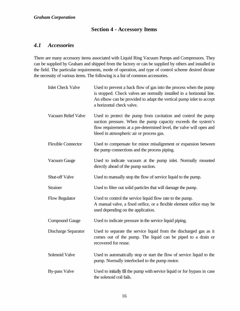
Section 4 - Accessory Items
4.1 Accessories
There are many accessory items associated with Liquid Ring Vacuum Pumps and Compressors. Theycan be supplied by Graham and shipped from the factory or can be supplied by others and installed inthe field. The particular requirements, mode of operation, and type of control scheme desired dictatethe necessity of various items. The following is a list of common accessories.
Inlet Check Valve Used to prevent a back flow of gas into the process when the pumpis stopped. Check valves are normally installed in a horizontal line.An elbow can be provided to adapt the vertical pump inlet to accepta horizontal check valve.
Vacuum Relief Valve Used to protect the pump from cavitation and control the pumpsuction pressure. When the pump capacity exceeds the system’sflow requirements at a pre-determined level, the valve will open andbleed in atmospheric air or process gas.
Flexible Connector Used to compensate for minor misalignment or expansion betweenthe pump connections and the process piping.
Vacuum Gauge Used to indicate vacuum at the pump inlet. Normally mounteddirectly ahead of the pump suction.
Shut-off Valve Used to manually stop the flow of service liquid to the pump.
Strainer Used to filter out solid particles that will damage the pump.
Flow Regulator Used to control the service liquid flow rate to the pump.A manual valve, a fixed orifice, or a flexible element orifice may beused depending on the application.
Compound Gauge Used to indicate pressure in the service liquid piping.
Discharge Separator Used to separate the service liquid from the discharged gas as itcomes out of the pump. The liquid can be piped to a drain orrecovered for reuse.
Solenoid Valve Used to automatically stop or start the flow of service liquid to thepump. Normally interlocked to the pump motor.
By-pass Valve Used to initially fill the pump with service liquid or for bypass in casethe solenoid coil fails.

Graham Corporation
17
Recirculation Pump Used to circulate the service liquid recovered from the dischargeseparator in some total recovery systems.
Heat Exchanger Used to remove heat from the recirculated service liquid.
Atmospheric Used to provide a suction pressure lower than the pump isAir Ejector capable of when operating alone. It may be added to a two stage
pump to provide an inlet pressure as low as 3 mm HgA. Theoperation of the air ejector is similar to that of a steam ejector.Atmospheric air or recycled gas from the discharge separator is usedas the motive force for compressing the process gas from the systemdesign pressure up to the inlet pressure of the pump. To enhancepumping capacity at a higher suction pressure, an optional motive airshut-off valve or by-pass valve can be added. (See Figure 2)
P r o c e s s I n l e t
Op t iona l
By-pass
V a l v e
Liqu id R ing
V a c u u m P u m p
D i s c h a r g e
Atmosphe r i c
A i r E j e c t o r
T y p i c a l A t m o s p h e r i c A i r E j e c t o r
Op t iona l
Shut -of f
V a l v e
Atmosphe r i c
A i r I n l e t
Figure 2

Graham Corporation
18
Section 5 - Maintenance
5.1 Performance
Optimum performance and long service life are dependent upon good maintenance procedures andperiodic inspections. When preparing to dismantle a pump, make provisions for the safe handling ofheavy parts.
5.2 Series 3 Pump Estimated Weights ( lbs.)*
Cast IronPump Model Dry Operating Flooded Pump Model Dry Operating Flooded3PV21030 51 54 56 3PV22030 55 58 613PV21070 53 56 58 3PV22070 62 65 683PV31060 88 92 97 3PV22090 66 69 733PV31110 132 142 151 3PV32080 100 110 1203PV41160 176 188 200 3PV42110 187 200 207
3PV42160 192 209 2273PV52120 342 364 3863PV52160 377 403 4303PV52200 397 428 459
Stainless SteelPump Model Dry Operating Flooded Pump Model Dry Operating Flooded3PV21030 N/A N/A N/A 3PV22030 N/A N/A N/A3PV21070 N/A N/A N/A 3PV22070 N/A N/A N/A3PV31060 93 97 102 3PV22090 N/A N/A N/A3PV31110 139 149 159 3PV32080 105 116 1263PV41160 185 197 210 3PV42110 196 210 217
3PV42160 202 220 2383PV52120 359 382 4053PV52160 396 423 4523PV52200 417 449 482
* Pump weights apply to PV or PC design. For units in kg, multiply lbs. by 0.454
Table 2

Graham Corporation
19
5.3 Shaft Bearings
The Series 3 pumps use sealed-for-life bearings that are not regreasable.
The standard bearings are rated for an L10h life of 80,000 hours. The temperature of the bearingsshould not exceed 140ºF (60ºC). Overheating may be due to misalignment of the shafts or a badbearing.
5.4 Mechanical Seals
The Series 3 pumps are fitted with single acting mechanical shaft seals. They should be replaced whenworn, scratched, or cracked, or when the rotating segment no longer grips the shaft.
When replacing the mechanical seals, clean the shaft thoroughly. The seal faces must be protectedduring installation from particles which may scratch the surfaces.
CAUTION: DO NOT RUN THE PUMP WITHOUT SERVICE LIQUID ANDSHAFT SEAL FLUID.
5.5 Storage
If a pump is to be out of service, it should be protected internally from rusting by using a rust inhibitor.The pump should be drained completely by removing all the lower plugs. Install the plugs and fill withOakite HPO (or equal) preservative solution. Remove the manifold(s) and spray the insides withpreservative. Rotate the pump manually to circulate the solution. Drain the pump to below the shaftcenterline and replace the manifold(s). This procedure may be disregarded for pumps made ofstainless steel.
Seal any openings to prevent foreign material from entering the pump.
The pump shaft should be rotated each week to distribute the preservative and to prevent flat spots onthe bearings. Document the time, date, and by whom this procedure was performed.
The manifold(s) should be re-sprayed monthly and the pump checked to see that the preservative ismaintained. This will protect the pump for up to twelve months.
Pumps stored at low temperatures may need to be protected from freezing either by drainingcompletely or by using an anti-freeze solution.
Pumps with V-belt drives should have the belts loosened to relieve the belt tension during storage. Donot store near running electric motors as ozone produced is detrimental to the rubber in the belts.
Graham Corporation
20
5.6 Removal from storage
The pump should be drained and flushed if necessary to remove the preservative solution. Refer toSection 3.1 of this manual for the recommended start-up procedure.
CAUTION: THE OAKITE HPO PRESERVATIVE SOLUTION IS PETROLEUMBASED AND MUST BE DISPOSED OF IN ACCORDANCE WITHALL LOCAL, STATE, AND FEDERAL REGULATIONS.
An MSDS form is included in the back of this manual.

Graham Corporation
21
5.7 Troubleshooting Chart
Problem Cause SolutionReducedCapacity
• Speed too low• Leak in suction line• Service liquid temperature too high• Insufficient or excess service liquid• Excessive back pressure
• Check power supply and transmission• Repair• Check coolant flow & heat exchanger• Provide correct flow rate• Eliminate cause of back pressure
ExcessiveNoise
• Excessive or insufficient service liquid• Shaft misalignment• Defective bearing• Cavitation
• Back pressure
• Adjust flow rate• Realign shafts• Replace bearing• Open attenuation valve or adjust vacuum
relief valve• Eliminate cause of back pressure
High PowerConsumption
• Excessive service liquid• Shaft misalignment• Excessive back pressure• Defective bearing• Improperly mounted pump
• Reduce flow rate• Realign shafts• Eliminate cause of back pressure• Replace bearing• Make sure surface is level and all feet touch
the surface, shim if necessary.Overheating • Service liquid temperature too high
• Insufficient service liquid• Shaft misalignment• Defective bearing
• Check coolant flow & heat exchanger• Provide correct flow rate• Realign shafts• Replace bearing
Vibration • Shaft misaligned• Pump or baseplate not properly anchored• Defective bearing• Improperly mounted pump
• Cavitation
• Back pressure• Excessive service liquid
• Realign shafts• Anchor• Replace bearing• Make sure surface is level and all feet touch
the surface, shim if necessary.• Open attenuation valve or adjust vacuum
relief valve• Eliminate cause of back pressure• Provide correct flow rate
AbnormalBearing Wearor Failure
• Shaft misalignment• Piping load on pump flange• Mechanical seal leakage• Shaft flinger missing
• Realign shafts• Support connecting pipe work• Replace seals• Replace flinger
Shaft Will NotTurn orPartiallySeizes
• Scale build-up• Foreign object in pump• Piping load on pump flange• Improperly mounted pump
• Soft Foot
• Descale pump• Remove foreign object• Support connecting pipe work• Make sure surface is level and all feet touch
the surface, shim if necessary.• Correct pump / motor mounting
Table 3

Graham Corporation
22
Section 6 - Disassembly And Reassembly Procedures
6.1 General
Complete disassembly of the pump is seldom necessary and it may only need to be disassembled to thepoint required to repair or service it. Specific instructions are included with the documentation sent withyour liquid ring pump. The cross-section drawing and parts list should be referred to when servicing thepump and when ordering spare parts.
Before any servicing takes place, it is recommended that gasket compound, bearings, and mechanicalseals be on hand as spare parts. The stocking of additional items beyond these basic wearing parts isdependent upon the type of application, compatibility of pump materials with the process gas andservice liquid, degree of corrosion and erosion to which the pump is subjected, importance of pumpreliability to the process, etc.
When ordering spare parts, be sure to identify the pump size, serial number, part name and referencenumber, and if available, original purchase order number, Graham job number, or a drawing number.
6.2 Impeller End Clearances
Refer to Table 4 for the impeller end clearances. These values are for each side of the impeller in eachstage. These clearances are extremely important for optimum pump performance. Also refer to thedismantling and reassembly procedures that were provided with the documentation sent with yourpump.
Impeller End Clearances *
PumpFrameSize
Cast Iron Construction 316SS Construction
30000 0.004"-0.006" 0.006"-0.009"40000 0.004"-0.006" 0.006"-0.009"50000 0.006"-0.008" 0.009"-0.012"
* For units in mm, multiply inches by 25.4
Table 4

Graham Corporation
23
A) Non-Gasketed Pumps
Series 3 pumps do not require casing gaskets, but use a joint sealing compound between the impellercasings and the end plates. They are machined for a metal to metal fit. Refer to Figures 3 & 4. Theheaders or crossover manifolds require a gasket.
S e a l i n g
C o m p o u n dS e a l i n g
C o m p o u n dSingle StageFigure 3
**
G a s k e t
Seal ing
C o m p o u n dTwo S tage
F i g u r e 4
Seal ing
C o m p o u n d
S e a l i n g
C o m p o u n d o n
certain s i z e s
* *
**
Gaske t
* Impeller clearance locations.

Graham Corporation
24
6.3 Tie Rod Torque Values
Table 5 includes torque values for re-assembling the pumps.
Pump Frame Size Tie Rod Torque *20000 30 ft.-lbf30000 40 ft.-lbf40000 40 ft.-lbf50000 40 ft.-lbf
* For units in N-m, multiply ft.-lbf by 1.355
Table 5
6.4 Bearing Data
The correct bearing fit class needs to be used in order for proper operation. Do not use a C3 fit asit is too loose and will cause damage to the pump. Table 6 provides correct bearing data for thepumps.
Pump FrameSize
SKF BearingNumber
Type Bearing FitClass
(Normal Fit)
Bearing JournalDiameter & Tolerance
(µm)
ToleranceClass
30000 6306/2RS1 Ball Bearing, Single AFBMA 0 30 mm, +15, +2 k640000 6306/2RS1 Row, Deep Groove, AFBMA 0 30 mm, +15, +2 k650000 6308/2RS1 Double Seals (SFL) AFBMA 0 40 mm, +18, +2 k6
Table 6
Graham Corporation
25
Section 7 - Warranty
THE FOLLOWING IS IN LIEU OF ALL WARRANTIES OF GRAHAM EXPRESSED ORIMPLIED AND ALL IMPLIED WARRANTIES, INCLUDING BUT NOT LIMITED TO ANYIMPLIED WARRANTY OF MERCHANTABILITY OR FITNESS FOR A PARTICULARPURPOSE, AND/OR ANY OTHER OBLIGATION ON THE PART OF GRAHAM AREHEREBY EXCLUDED:
Graham, except as otherwise provided, warrants goods of its own manufacture against faultyworkmanship or the use of defective materials, under normal use and service, and that such goods willconform to mutually agreed upon written specifications, drawings, and is guaranteed to meet specifiedperformance requirements, for a period of twelve (12) months from date of shipment of the goods fromthe factory.
Graham assumes no responsibility for deterioration of the equipment due to corrosion, erosion, or flowinduced tube vibration, or for fouling, maintenance problems or any other causes not specificallycovered under the foregoing warranty. The sole remedy of Buyer with respect to any part notconforming to any warranty of Graham shall be the repair or, at Graham’s option, replacement of anydefective part at the point of manufacture, Buyer assuming all costs of removal, shipping, andreinstallation, provided that immediate written notice of the defect has been given to Graham, andGraham shall not be liable for any other expenses incurred because of failure of any part to meetGraham’s warranty, nor for any special, indirect or consequential damages. Material returned toGraham’s factory without its written consent will not be accepted. No back charges will be honoredwithout Graham’s advance approval of the work to be performed. Graham’s liability on any claim ofany kind, including negligence, for any loss or damage arising out of, connected with, or resulting fromthis transaction, or the design, manufacture, sale, delivery, resale, installation, technical direction ofinstallation, inspection, repair, operation, or use of any equipment covered by or furnished hereundershall in no case exceed the price paid by Buyer for the equipment. Graham also disclaims all liability,whether in contract, tort, warranty, or otherwise, to any party other than the Buyer.
In the event the pumps are altered or repaired by any person or entity other than Graham, withoutwritten approval by Graham, all warranties are void. Bearings and shaft seals are warranted only tothe extent of, and pursuant to, the original manufacturer's warranty

Graham Corporation
26
Appendix A- MATERIAL SAFETY DATA SHEET

Graham Corporation
27

Graham Corporation
28
Graham Corporation
29

Graham Corporation
30
Appendix B- RETURN MATERIAL AUTHORIZATION FORM
RETURN MATERIAL AUTHORIZATON FORM
TO: Pump Service Department Date:
FROM:
RMA Number:
This form must be filled out completely before any work will be started onthe equipment being returned. This is to ensure the safety of all Graham
employees who may come in contact with this equipment.
MSDS (Material Safety Data Sheet) must be included for all material handledby the equipment. Work on the equipment will be held pending receipt of
the MSDS.
The equipment must be cleaned prior to shipping back to Graham.Equipment returned in an unsatisfactory condition will be returned to the
sender for cleaning.
Customer Data
Customer: Contact Person:
Mailing Address: Phone Number:
Fax Number:
Graham Equipment Information
Graham Serial Number:
Equipment Being Returned:
Reason for Return:
Material Handled by Equipment:
Send equipment and MSDS sheets to the address above, Attn.: Pump ServiceDept.
This form is to be filled out by Graham (Batavia) personnel only. RMAforms filled out by agents and customers will not be accepted!
S
MA
PL
E