Embed Size (px)
Citation preview
LIQUID RESISTANCE MOTOR STARTERSSlipring Motors upto 5000 KW.
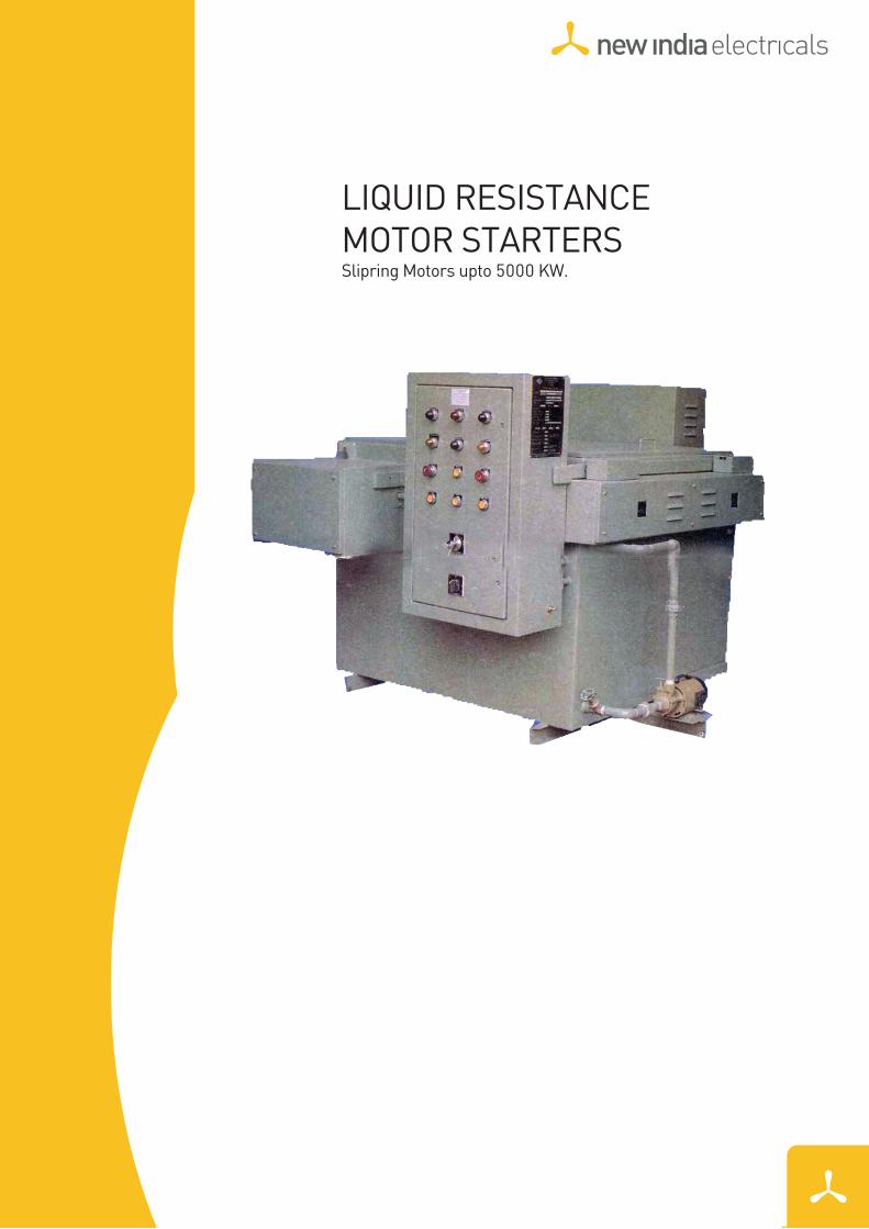
Moving and Fixed Electrodes are of Fabricated Sheet Steel (zinc
plated) of suitable profile and size. One set of Fixed Electrodes are
mounted on Epoxy Cast Insulators and connected to Main Terminals,
Other set of Moving Electrodes are shorted and earthed. Electrodes of
Stainless Steel can also be supplied if required.
A Control Box is provided for electrical operation, housing all Relays,
Contractors, Push Buttons, Indicating Lamps, Switches and other
necessary electrical items.
Forward and Reverse contractors with Over Load Relays are provide
to actuate the Pilot Motor. Contractors are inter loacked such that
only one Contractor can be operated at a time. Necessary
interlocking circuits are provided for the safety of Main Motor.
ŸSALIENT FEATURES
Ÿ Robust and Non-Flammable construction.
Ÿ Simple in Operation.
Ÿ Provides smooth and stepless cutting of resistance in rotor circuit of the Motor, reducing Starting Current and increasing Starting Torque of Slip-Ring Induction Motor.
Ÿ Requires Minimum Initial Investment and Negligible Maintenance.
Ÿ Available in various sizes for motors upto 5000 KW.
Ÿ Designed to give equal resistance in each phase with special profile of Fixed and Moving Electrodes.
Ÿ Need cheap and simple solution of Sodium Carbonate (Washing Soda) and water as electrolyte, thus totally eliminating the costly and scarce insulating oil.
Ÿ Provided with large volume of electrolyte for better heat dissipation and ample cross-section of copper contacts and current carrying parts for less temperature - rise.
Ÿ Tank and Cover are of welded steel construction and provided with Relief Vent, Filling & Over - Flow Socket, Drain Plug etc.,
Ÿ Inner side of Electrolyte Tank is lined with FRP for corrosion resistance to increase life of Tank.
Ÿ Poly-Propylene phase barriers are used to increase insulation level between phase to phase and phase to earth.
Ÿ Shorting Switch or contractor is provided outside the electrolyte tank to Short-Circuit Liquid Resistance when motor attains full speed.
Ÿ contacts and Electrodes are easily accessible for maintenance and replacement.
Ÿ Fitted with Epoxy Cast insulators and Bushings for better insulation and longer life.
Ÿ distinct and clear indication of electrolyte level from outside through Electrolyte level gauge. No need to open the cover.
Ÿ Fool-Proof interlocking System is Provided by interlocking contacts to prevent closing of Stator Switch unless full Resistance is in rotor circuit.
Ÿ Timer to trip Stator Switch is provided if Liquid Resistance is not cut within predetermined time.
Ÿ Manual or Motor Operated Mechanism.
Ÿ Solid State Liquid level Controller with alarm and contacts. Dial type Liquid level Controller with alarm and contacts.
Ÿ Dial type liquid Temperature Indicator and controller with alarm and trip contacts.
Ÿ Can be supplied suitable for different modes of operations like, Local / Remote or Automatic through Stator Switch, etc.,
Ÿ Current Relay can be provided for synchronisation of Rotor Resistance Cutting and Motor Acceleration.
ELECTRODE SYSTEM CONTROL SYSTEM
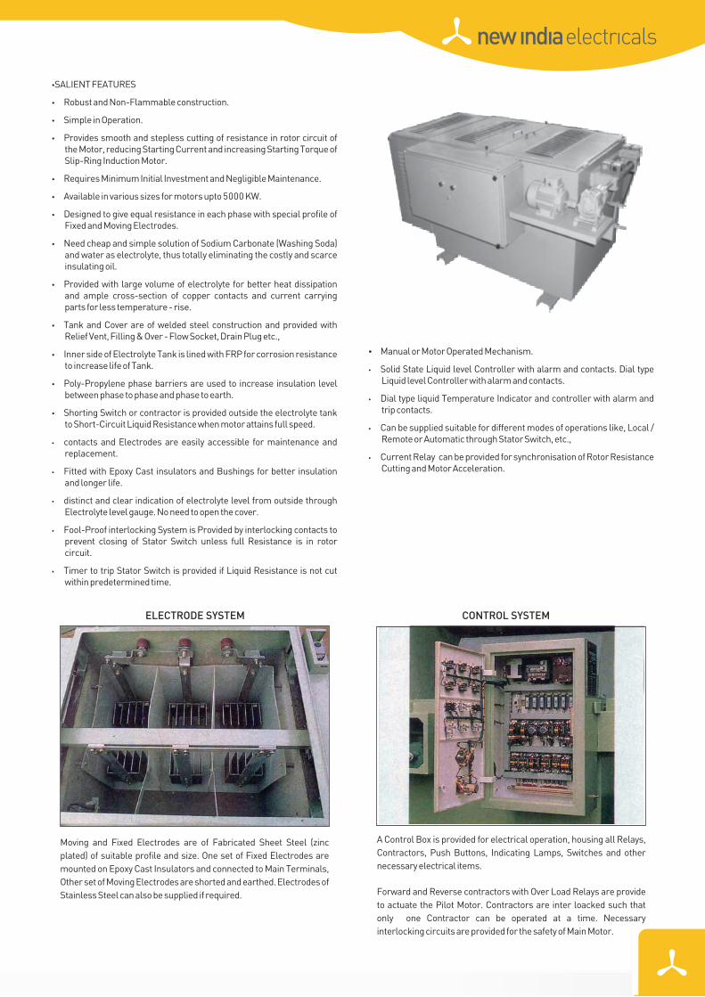
Driving Mechanism is provided in the Mechanism Box containing pilot
motor, Gear Box, set of Spur Gear and pinion, transmitting power to
moving channel through a Shaft fitted with Sprocket and chain
arrangement, the Moving Electrodes are fixed to the channel fitted
with rollers moving smoothly on horizontal guide rails. During
emergency or for maintenance, the mechanism can also be operated
manually by a Hand wheel after disengaging the Motor Drive with the
help of Declutching arrangement provided To arrest the movement of
the Moving System at the end position, Oil Tight Limit Switch are
provided.
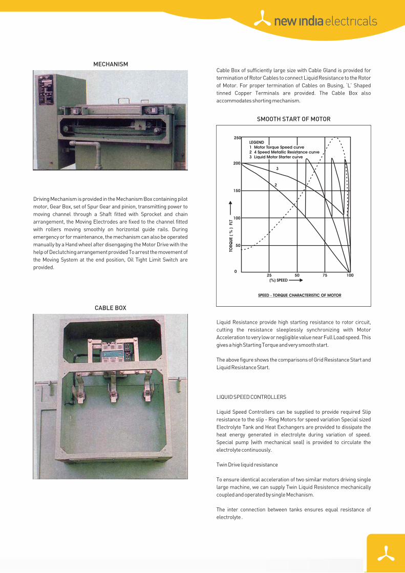
Liquid Resistance provide high starting resistance to rotor circuit,
cutting the resistance sleeplessly synchronizing with Motor
Acceleration to very low or negligible value near Full Load speed. This
gives a high Starting Torque and very smooth start.
The above figure shows the comparisons of Grid Resistance Start and
Liquid Resistance Start.
LIQUID SPEED CONTROLLERS
Liquid Speed Controllers can be supplied to provide required Slip
resistance to the slip - Ring Motors for speed variation Special sized
Electrolyte Tank and Heat Exchangers are provided to dissipate the
heat energy generated in electrolyte during variation of speed.
Special pump (with mechanical seal) is provided to circulate the
electrolyte continuously.
Twin Drive liquid resistance
To ensure identical acceleration of two similar motors driving single
large machine, we can supply Twin Liquid Resistence mechanically
coupled and operated by single Mechanism.
The inter connection between tanks ensures equal resistance of
electrolyte .
Cable Box of sufficiently large size with Cable Gland is provided for
termination of Rotor Cables to connect Liquid Resistance to the Rotor
of Motor. For proper termination of Cables on Busing, ‘L’ Shaped
tinned Copper Terminals are provided. The Cable Box also
accommodates shorting mechanism.
MECHANISM
SMOOTH START OF MOTOR
CABLE BOX
SPEED - TORQUE CHARACTERISTIC OF MOTOR
(%) SPEED25 50
50
075 100
100
200
250
3
2
150
TORQ
UE
( %
)
FLT
LEGEND1 Motor Torque Speed curve2 4 Speed Metallic Resistance curve3 Liquid Motor Starter curve
LEGEND1 Motor Torque Speed curve2 4 Speed Metallic Resistance curve3 Liquid Motor Starter curve
NIE
/FL
PM
TR
/03
08
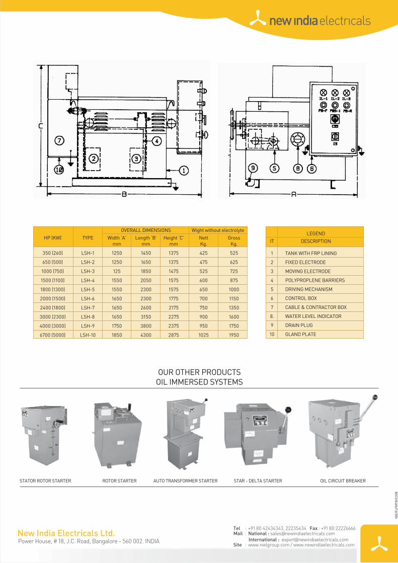
OUR OTHER PRODUCTSOIL IMMERSED SYSTEMS
STATOR ROTOR STARTER ROTOR STARTER AUTO TRANSFORMER STARTER STAR - DELTA STARTER OIL CIRCUIT BREAKER
OVERALL DIMENSIONS Wight without electrolyte
HP (KW) TYPE Width ‘A’ Length ‘B’ Height ‘C’ Nett Grossmm mm mm Kg. Kg.
350 (260) LSH-1 1250 1450 1375 425 525
650 (500) LSH-2 1250 1650 1375 475 625
1000 (750) LSH-3 125 1850 1475 525 725
1500 (1100) LSH-4 1550 2050 1575 600 875
1800 (1300) LSH-5 1550 2300 1575 650 1000
2000 (1500) LSH-6 1650 2300 1775 700 1150
2400 (1800) LSH-7 1650 2600 2175 750 1350
3000 (2300) LSH-8 1650 3150 2275 900 1600
4000 (3000) LSH-9 1750 3800 2375 950 1750
6700 (5000) LSH-10 1850 4300 2875 1025 1950
LEGEND
IT DESCRIPTION
1 TANK WITH FRP LINING
2 FIXED ELECTRODE
3 MOVING ELECTRODE
4 POLYPROPLENE BARRIERS
5 DRIVING MECHANISM
6 CONTROL BOX
7 CABLE & CONTRACTOR BOX
8. WATER LEVEL INDICATOR
9 DRAIN PLUG
10 GLAND PLATE
Power House, # 18, J.C. Road, Bangalore - 560 002. INDIA
Tel : +91 80 42434343, 22235434 Fax : +91 80 22226666Mail : National : [email protected]
International : [email protected] : www.nielgroup.com / www.newindiaelectricals.com