Embed Size (px)
Citation preview
Linking Autodesk® Revit® Structure and Autodesk® Robot™ Structural Analysis: Beyond the Basics Brian Johnson, P.E. – Autodesk Tomasz Fudala – Autodesk
SE3904 This class focuses on advanced interoperability between Autodesk Revit Structure and Autodesk Robot Structural Analysis Professional software. You will learn best practices for transferring sloped and curved framing and curtain wall between Revit and Robot. We will demonstrate techniques for working with floor openings, analytical/rigid links, and framing offsets. Learn the advanced options that are available in the Revit-Robot link to facilitate model transfer and data fidelity. Increase your productivity by getting the most out of this powerful analytical link.
LearningObjectivesAt the end of this class, you will be able to:
Describe best practices and workflow for analytical modeling
Describe techniques for modeling complex framing
Send and update models between Revit and Robot
Apply appropriate send/update settings for Revit-Robot analytical link
AbouttheSpeaker Brian is a Structural Technical Specialist for Autodesk. He is an expert in structural modeling and design using Revit Structure. Brian is a licensed structural engineer with over 10 years of building design and consulting experience. During that time he worked as a Project Manager, and Principal on a variety of structures. He earned a B.S. in Civil Engineering from the University of Texas at Austin.
Tomasz is the Technical Marketing Manager for Structural Engineering Solutions at Autodesk. He has over 10 years of experience in the software industry and a comprehensive background and knowledge of Autodesk Revit Structure, AutoCAD Structural Detailing and Robot Structural Analysis Professional. Prior to Autodesk he worked for Robobat for 5 years in many capacities including Structural Engineering Subject Matter Expert. Tomasz received a Master of Science degree in Structural Engineering from the Cracow University of Technology in Poland.
Linking Autodesk® Revit® Structure and Autodesk® Robot™ Structural Analysis: Beyond the Basics
2
Bestpracticesandworkflowforanalyticalmodeling
PrepareYourEnvironment
CoordinationwithArchitectsSince most of us work with Architectural models, it may be important for you to discuss the impact of how the architect is modeling certain elements with respect to your internal analysis workflow.
Be wary of Architectural elements v. Structural elements in a model. Architectural Walls and Columns do not have an Analytical Model component!
Linked model elements are not pulled into Robot Structural Analysis Professional and may not be transferred to other structural analysis software. Model all structural elements in the host model.
TemplatesWe typically think of Revit templates in the context of drafting standards. When transferring data in an analysis workflow also consider updates to your template(s) that will streamline the data transfer with analysis tools. Additionally, consider how you might adjust analysis software templates as well.
ContentGenerally, content must exist in Revit and in Robot Structural Analysis Professional for a transfer to occur. Standard sections like Wide flange shapes transfer without any special consideration. Custom shapes need to be created in both Revit and in Robot Structural Analysis Professional. See sections on complex framing and Content Generator for additional commentary. Here are a few general tips:
The Type Name needs to match exactly in Revit and Robot for custom content Know how to create custom Revit families or add section Types to Revit family Type Catalog text files Know how to create and store custom shapes in Robot Structural Analysis Professional
RevitViewFilters&ViewTemplatesA great way to check your model before transferring it to analysis software is to use View Filters and View Templates in Revit. These filtered views make it easy to see where you have mismatched parameters or erroneous conditions in the model.
Create Criteria-based filters for parameters like Analyze As (e.g. Gravity or Lateral) Create view templates to reflect the criteria-based filters (e.g. Gravity = Blue, Lateral = Red) Save the filters, view templates, and Views in your Revit template
RevitSchedulesAnother way to check the model is to leverage Revit Schedules. Schedules also provide visual clues to incorrect parameters in the model. Create these Schedules in your Revit template so they are readily available when you start a new project. Examples include the following:
End Release schedule for Bracing or moment frames Composite Beam parameters for Studs and Camber Load schedules
Linking Autodesk® Revit® Structure and Autodesk® Robot™ Structural Analysis: Beyond the Basics
3
LoadsInclude typical Load Cases and simple Load Combinations in your Revit template. As with the previously described settings, having these in your template will help to streamline the analysis workflow. Robot Structural Analysis Professional has a Load Combination generator, so it is faster to let Robot generate the more complicated sets of Load Combinations for wind and seismic loading.
PrepareYourModel
UseRevitDatumsRevit datums are important for traditional uses like locating columns but also have Revit-specific uses like constraining columns. They are also important for structural analysis in that they help prevent the creation of duplicate nodes (and subsequent instabilities) in Robot Structural Analysis Professional (and other tools as well).
Make sure your Analytical model elements (especially Braces) are aligned with and/or Locked to a Grid, Level, or named Reference Plane
If elements are supposed to be offset a few inches from a Grid, then create a named Reference Plane at the appropriate offset to use for alignment and Locking
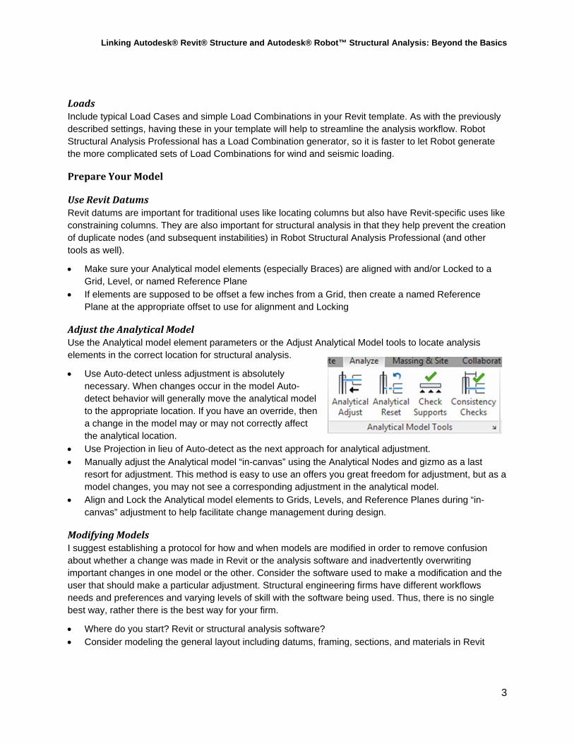
AdjusttheAnalyticalModelUse the Analytical model element parameters or the Adjust Analytical Model tools to locate analysis elements in the correct location for structural analysis.
Use Auto-detect unless adjustment is absolutely necessary. When changes occur in the model Auto-detect behavior will generally move the analytical model to the appropriate location. If you have an override, then a change in the model may or may not correctly affect the analytical location.
Use Projection in lieu of Auto-detect as the next approach for analytical adjustment. Manually adjust the Analytical model “in-canvas” using the Analytical Nodes and gizmo as a last
resort for adjustment. This method is easy to use an offers you great freedom for adjustment, but as a model changes, you may not see a corresponding adjustment in the analytical model.
Align and Lock the Analytical model elements to Grids, Levels, and Reference Planes during “in-canvas” adjustment to help facilitate change management during design.
ModifyingModelsI suggest establishing a protocol for how and when models are modified in order to remove confusion about whether a change was made in Revit or the analysis software and inadvertently overwriting important changes in one model or the other. Consider the software used to make a modification and the user that should make a particular adjustment. Structural engineering firms have different workflows needs and preferences and varying levels of skill with the software being used. Thus, there is no single best way, rather there is the best way for your firm.
Where do you start? Revit or structural analysis software? Consider modeling the general layout including datums, framing, sections, and materials in Revit
Linking Autodesk® Revit® Structure and Autodesk® Robot™ Structural Analysis: Beyond the Basics
4
Determine if modeling Boundary Conditions, End Releases, and Loading is more effective in Revit or in the structural analysis software. Some objects like special loads or complex end release parameters are available in Robot Structural Analysis Professional software but not in Revit
Techniquesformodelingcomplexframing
CurvedFraming
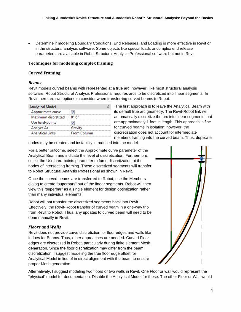
BeamsRevit models curved beams with represented at a true arc; however, like most structural analysis software, Robot Structural Analysis Professional requires arcs to be discretized into linear segments. In Revit there are two options to consider when transferring curved beams to Robot.
The first approach is to leave the Analytical Beam with its default true arc geometry. The Revit-Robot link will automatically discretize the arc into linear segments that are approximately 1 foot in length. This approach is fine for curved beams in isolation; however, the discretization does not account for intermediate members framing into the curved beam. Thus, duplicate
nodes may be created and instability introduced into the model.
For a better outcome, select the Approximate curve parameter of the Analytical Beam and indicate the level of discretization. Furthermore, select the Use hard-points parameter to force discretization at the nodes of intersecting framing. These discretized segments will transfer to Robot Structural Analysis Professional as shown in Revit.
Once the curved beams are transferred to Robot, use the Members dialog to create “superbars” out of the linear segments. Robot will then view this “superbar” as a single element for design optimization rather than many individual elements.
Robot will not transfer the discretized segments back into Revit. Effectively, the Revit-Robot transfer of curved beam in a one-way trip from Revit to Robot. Thus, any updates to curved beam will need to be done manually in Revit.
FloorsandWallsRevit does not provide curve discretiztion for floor edges and walls like it does for Beams. Thus, other approaches are needed. Curved Floor edges are discretized in Robot, particularly during finite element Mesh generation. Since the floor discretization may differ from the beam discretization, I suggest modeling the true floor edge offset for Analytical Model in lieu of in direct alignment with the beam to ensure proper Mesh generation.
Alternatively, I suggest modeling two floors or two walls in Revit. One Floor or wall would represent the “physical” model for documentation. Disable the Analytical Model for these. The other Floor or Wall would
Linking Autodesk® Revit® Structure and Autodesk® Robot™ Structural Analysis: Beyond the Basics
5
represent the Analytical element. Leave the Analytical Model enabled, but Hide the visibility of the object in the Documentation views with view filters. These “analytical” versions would be modeled with linear segments and will transfer to and analyze correctly in Robot.
SlopedFraming
ModelinginRevitLike curved elements, sloped framing adds some complexity to the model. There are many different ways to model sloped floors and framing, but there are a few best practices I suggest for linking with Robot.
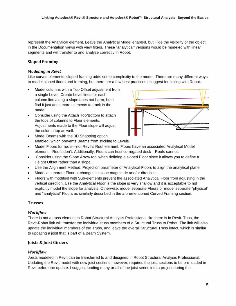
Model columns with a Top Offset adjustment from a single Level. Create Level lines for each column line along a slope does not harm, but I find it just adds more elements to track in the model.
Consider using the Attach Top/Bottom to attach the tops of columns to Floor elements. Adjustments made to the Floor slope will adjust the column top as well.
Model Beams with the 3D Snapping option enabled, which prevents Beams from sticking to Levels.
Model Floors for roofs—not Revit’s Roof element. Floors have an associated Analytical Model element—Roofs don’t. Additionally, Floors can host corrugated deck—Roofs cannot.
Consider using the Slope Arrow tool when defining a sloped Floor since it allows you to define a Height Offset rather than a slope.
Use the Alignment Method: Projection parameter of Analytical Floors to align the analytical plane. Model a separate Floor at changes in slope magnitude and/or direction. Floors with modified with Sub-elements prevent the associated Analytical Floor from adjusting in the
vertical direction. Use the Analytical Floor is the slope is very shallow and it is acceptable to not explicitly model the slope for analysis. Otherwise, model separate Floors or model separate “physical” and “analytical” Floors as similarly described in the aforementioned Curved Framing section.
Trusses
WorkflowThere is not a truss element in Robot Structural Analysis Professional like there is in Revit. Thus, the Revit-Robot link will transfer the individual truss members of a Structural Truss to Robot. The link will also update the individual members of the Truss, and leave the overall Structural Truss intact, which is similar to updating a joist that is part of a Beam System.
Joists&JoistGirders
WorkflowJoists modeled in Revit can be transferred to and designed in Robot Structural Analysis Professional. Updating the Revit model with new joist sections; however, requires the joist sections to be pre-loaded in Revit before the update. I suggest loading many or all of the joist series into a project during the
Linking Autodesk® Revit® Structure and Autodesk® Robot™ Structural Analysis: Beyond the Basics
6
beginning of project (or the template if you use joists often) to mitigate this issue. Once the project is designed, purge the unused joists from the model.
Revit has some joist girder families out of the box, but Robot Structural Analysis Professional does not. Engineers can create a library of joist girders using the Parametric tab of the joist definition tool or perhaps modify the SJI joist library file (XML) to include joist girders. Once Robot and Revit both have joist girder sections with matching type names, the Revit-Robot link works without issue.
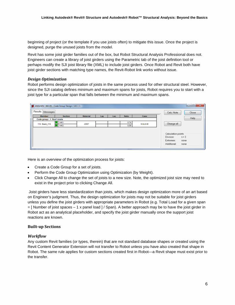
DesignOptimizationRobot performs design optimization of joists in the same process used for other structural steel. However, since the SJI catalog defines minimum and maximum spans for joists, Robot requires you to start with a joist type for a particular span that falls between the minimum and maximum spans.
Here is an overview of the optimization process for joists:
Create a Code Group for a set of joists. Perform the Code Group Optimization using Optimization (by Weight). Click Change All to change the set of joists to a new size. Note, the optimized joist size may need to
exist in the project prior to clicking Change All.
Joist girders have less standardization than joists, which makes design optimization more of an art based on Engineer’s judgment. Thus, the design optimization for joists may not be suitable for joist girders unless you define the joist girders with appropriate parameters in Robot (e.g. Total Load for a given span = [ Number of joist spaces – 1 x panel load ] / Span). A better approach may be to have the joist girder in Robot act as an analytical placeholder, and specify the joist girder manually once the support joist reactions are known.
Built‐upSections
WorkflowAny custom Revit families (or types, therein) that are not standard database shapes or created using the Revit Content Generator Extension will not transfer to Robot unless you have also created that shape in Robot. The same rule applies for custom sections created first in Robot—a Revit shape must exist prior to the transfer.
Linking Autodesk® Revit® Structure and Autodesk® Robot™ Structural Analysis: Beyond the Basics
7
SendandupdatemodelsbetweenRevitandRobot
ContentGenerator
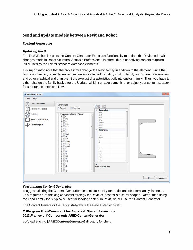
UpdatingRevitThe Revit/Robot link uses the Content Generator Extension functionality to update the Revit model with changes made in Robot Structural Analysis Professional. In effect, this is underlying content mapping utility used by the link for standard database elements.
It is important to note that the process will change the Revit family in addition to the element. Since the family is changed, other dependencies are also affected including custom family and Shared Parameters and other graphical and primitive (Solids/Voids) characteristics built into custom family. Thus, you have to either change the family back after the Update, which can take some time, or adjust your content strategy for structural elements in Revit.
CustomizingContentGeneratorI suggest tailoring the Content Generator elements to meet your model and structural analysis needs. This requires a re-thinking of content strategy for Revit, at least for structural shapes. Rather than using the Load Family tools typically used for loading content in Revit, we will use the Content Generator.
The Content Generator files are installed with the Revit Extensions at:
C:\Program Files\Common Files\Autodesk Shared\Extensions 2013\Framework\Components\AREXContentGenerator
Let’s call this the {AREXContentGenerator} directory for short.
Linking Autodesk® Revit® Structure and Autodesk® Robot™ Structural Analysis: Beyond the Basics
8
The families that Content Generator uses are located at:
C:\Program Files\Common Files\Autodesk Shared\Extensions 2013\Data\Families
Drilling down this directory reveals Beam and Column families for standard database section (from AISC and CISC, for example) as well as “parametric” sections, which are customized sections for Steel, Concrete, and Timber.
There are three files that may also offer value in terms of customization.
{AREXContentGenerator}\en-US\Resources.xml
This file is used to map the section type to the Revit Family name. Note, descend into the localized directories for additional databases. The US file is shown here (en-US).
{AREXContentGenerator}\Configuration\FamilyMap.xml
This file maps section type names and databases. It also includes aliases of section names as well.
{AREXContentGenerator}\Configuration\Templates.xml
This file maps the section Families with the Revit families indicated above.
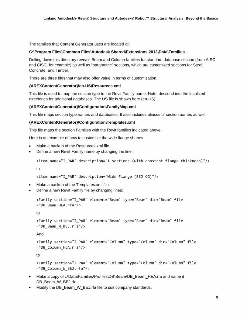
Here is an example of how to customize the wide flange shapes.
Make a backup of the Resources.xml file. Define a new Revit Family name by changing the line:
<item name="I_PAR" description="I‐sections (with constant flange thickness)"/>
to
<item name="I_PAR" description="Wide Flange (BEJ CG)"/>
Make a backup of the Templates.xml file. Define a new Revit Family file by changing lines:
<Family section="I_PAR" element="Beam" type="Beam" dir="Beam" file
="DB_Beam_HEA.rfa"/>
to
<Family section="I_PAR" element="Beam" type="Beam" dir="Beam" file
="DB_Beam_W_BEJ.rfa"/>
And
<Family section="I_PAR" element="Column" type="Column" dir="Column" file
="DB_Column_HEA.rfa"/>
to
<Family section="I_PAR" element="Column" type="Column" dir="Column" file
="DB_Column_W_BEJ.rfa"/>
Make a copy of ..\Data\Families\Profiles\DB\Beam\DB_Beam_HEA.rfa and name it DB_Beam_W_BEJ.rfa
Modify the DB_Beam_W_BEJ.rfa file to suit company standards.
Linking Autodesk® Revit® Structure and Autodesk® Robot™ Structural Analysis: Beyond the Basics
9
Repeat this operation for the Column family as well.
I suggest modifying the content shipped with the Content Generator rather than replacing them outright. The Content Generator families have additional parameters that are not included with the typical Revit families.
Consider making similar customizations to the Materials and Rebar settings in Content Generator. But always perform testing of the customizations before rolling out a change in a production environment.
Finally, update the Revit project template by replacing the appropriate families with the new Content Generator families.
AnalysisandDesignParameters
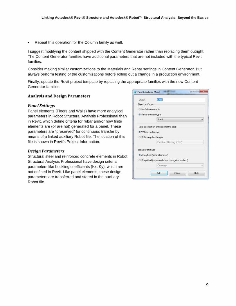
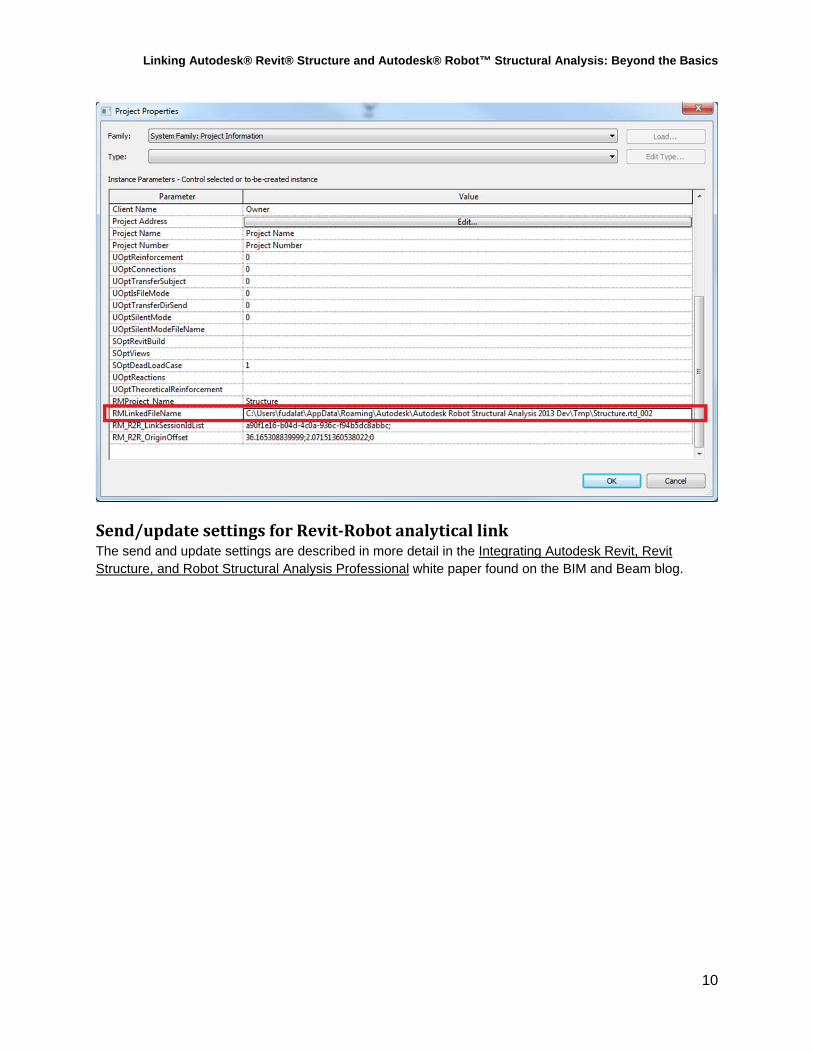
PanelSettingsPanel elements (Floors and Walls) have more analytical parameters in Robot Structural Analysis Professional than in Revit, which define criteria for rebar and/or how finite elements are (or are not) generated for a panel. These parameters are “preserved” for continuous transfer by means of a linked auxiliary Robot file. The location of this file is shown in Revit’s Project Information.
DesignParametersStructural steel and reinforced concrete elements in Robot Structural Analysis Professional have design criteria parameters like buckling coefficients (Kx, Ky), which are not defined in Revit. Like panel elements, these design parameters are transferred and stored in the auxiliary Robot file.
Linking Autodesk® Revit® Structure and Autodesk® Robot™ Structural Analysis: Beyond the Basics
10
Send/updatesettingsforRevit‐RobotanalyticallinkThe send and update settings are described in more detail in the Integrating Autodesk Revit, Revit Structure, and Robot Structural Analysis Professional white paper found on the BIM and Beam blog.