Embed Size (px)
Citation preview

Railway Group Standard
GK/RT0045
Issue Three
Date December 2012
Lineside Signals,Indicators and Layoutof Signals
Synopsis
This document defines the format,presentation and layout of linesidesignalling equipment that is used todisplay movement authority informationto infrastructure managers operatingstations, and railway undertakingpersonnel.
This document contains requirementsthat are amended under the RailwayGroup Standards Code (Issue Three) asa small scale change. Reference to theamended requirements is made in the‘Issue record’. All other parts of thedocument are unchanged from theprevious issue.
[This document contains one or more pages which contain colour] Copyright in the Railway Group Standards is owned byRail Safety and Standards Board Limited. All rights arehereby reserved. No Railway Group Standard (in wholeor in part) may be reproduced, stored in a retrievalsystem, or transmitted, in any form or means, without theprior written permission of Rail Safety and StandardsBoard Limited, or as expressly permitted by law.
RSSB Members are granted copyright licence inaccordance with the Constitution Agreement relating toRail Safety and Standards Board Limited.
In circumstances where Rail Safety and Standards BoardLimited has granted a particular person or organisationpermission to copy extracts from Railway GroupStandards, Rail Safety and Standards Board Limitedaccepts no responsibility for, nor any liability in connectionwith, the use of such extracts, or any claims arisingtherefrom. This disclaimer applies to all forms of media inwhich extracts from Railway Group Standards may bereproduced.
Published by:
RSSBBlock 2Angel Square1 Torrens StreetLondonEC1V 1NY
© Copyright 2012Rail Safety and Standards Board Limited
Uncontrolled When Printed Document to be superseded as of 07/03/2015
To be part superseded by GKRT0045 Iss 4, GKRT0057 Iss 1 and GKRT0058 Iss 1 published on 06/12/2014
Page 2 of 72 RSSB
Railway Group Standard
GK/RT0045
Issue Three
Date December 2012
Lineside Signals, Indicatorsand Layout of Signals
Issue record
Issue Date Comments
One 06 February 2010 Original document
Two 03 March 2012 Replaces issue one
Small scale change amendment to GK/RT0045issue two necessitated by revision of 2.3.1.2 and2.3.1.4 to permit the use of a bar of light or a lineof five lunar white light points to display theindication of route
Clauses 9.1.1, 9.1.2, 9.1.3, 9.1.4 and 9.1.5 relatingto identity of signals and indicators were removedfrom GK/RT0045 issue two as these weretransferred to GK/RT0009 issue four which waspublished in June 2011
Three 01 December 2012 Replaces issue two
Small scale change amendment to clause2.3.2.5c) to allow the use of the ‘X’ alphanumericroute indicator to additionally denote a movementalong a bi-directional line in the opposite directionto the normal flow of traffic
Amended or additional parts and/or sections of revised pages have been marked by avertical black line in the adjacent margin.
Superseded documents
The following Railway Group documents are superseded, either in whole or in part asindicated:
Superseded documents Sectionssuperseded
Date whensections aresuperseded
GK/RT0045, issue two, Lineside Signals,Indicators and Layout of Signals
All 02 March 2013
GK/RT0045, issue two, Lineside Signals, Indicators and Layout of Signals, ceases to be inforce and is withdrawn as of 02 March 2013.
Supply
The authoritative version of this document is available at www.rgsonline.co.uk.Uncontrolled copies of this document can be obtained from Communications, RSSB,Block 2, Angel Square, 1 Torrens Street, London EC1V 1NY, telephone 020 3142 5400 ore-mail [email protected]. Other Standards and associated documents can also beviewed at www.rgsonline.co.uk.
Uncontrolled When Printed Document to be superseded as of 07/03/2015
To be part superseded by GKRT0045 Iss 4, GKRT0057 Iss 1 and GKRT0058 Iss 1 published on 06/12/2014
RSSB Page 3 of 72
Railway Group Standard
GK/RT0045
Issue Three
Date December 2012
Lineside Signals, Indicatorsand Layout of Signals
Contents
Section Description Page
Part 1 Purpose and Introduction 51.1 Purpose 51.2 Introduction 51.3 Approval and authorisation of this document 7
Part 2 Requirements for Signalling Equipment 82.1 Display of operational information using the signalling system 82.2 Specification of lineside signals 82.3 Specification of route indicators 192.4 Specification of lineside indicators 232.5 Specification of lineside signs and buffer stops used as signals 30
Part 3 Layout of Signals: Requirements for Stop Signals 333.1 Provision of stop signals and signalling indicators 33
Part 4 Layout of Signals: Aspect Sequences 374.1 Requirements for cautionary aspect sequences 374.2 Requirements for banner repeating signal aspects 42
Part 5 Layout of Signals: Junction Signalling 445.1 Requirements for route indications 445.2 Junction signalling: colour light signal aspect sequences 475.3 Junction signalling: semaphore signal aspect sequences 525.4 Junction signalling: AWS requirements 545.5 Junction signalling: prohibited aspects 54
Part 6 Layout of Signals: Bi-directional Signalling 566.1 Bi-directional signalling 56
Part 7 Layout of Signals: Combinations of Signal Aspects and Indications 577.1 Combinations of signal aspects (including ERTMS level 2 operated lines) 577.2 Combinations of signal aspects and route indications 587.3 Signalling indications displayed in association with signal aspects 58
Part 8 Degraded Signalling 608.1 Degraded colour light signalling 60
Part 9 Application of this document 619.1 Application - infrastructure managers 619.2 Application - railway undertakings 629.3 Health and safety responsibilities 62
AppendicesAppendix A Signals and Indicators: Emitted Light Parameters 63Appendix B Signals and Indicators: Structure Requirements 64Appendix C Signals and Indicators: Standard Performance Categories 65Appendix D Positioning Criteria for Stop Signals on Electrified Lines 66
Definitions 69References 72
Uncontrolled When Printed Document to be superseded as of 07/03/2015
To be part superseded by GKRT0045 Iss 4, GKRT0057 Iss 1 and GKRT0058 Iss 1 published on 06/12/2014
Page 4 of 72 RSSB
Railway Group Standard
GK/RT0045
Issue Three
Date December 2012
Lineside Signals, Indicatorsand Layout of Signals
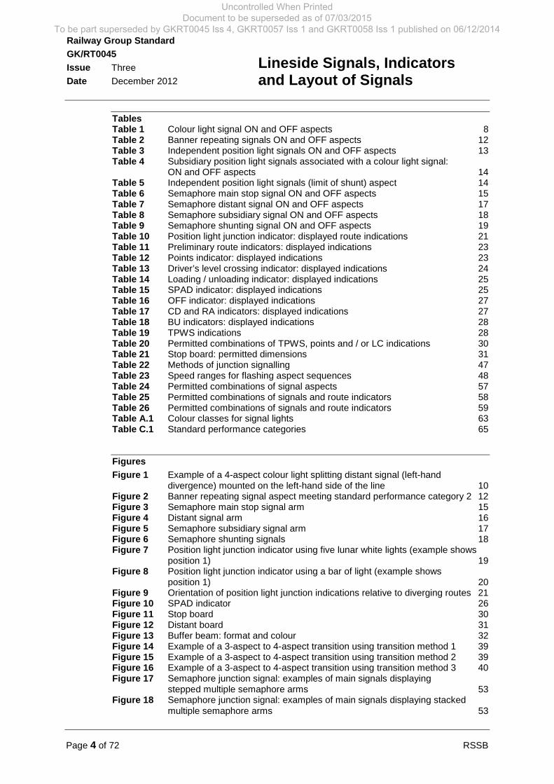
TablesTable 1 Colour light signal ON and OFF aspects 8Table 2 Banner repeating signals ON and OFF aspects 12Table 3 Independent position light signals ON and OFF aspects 13Table 4 Subsidiary position light signals associated with a colour light signal:
ON and OFF aspects 14Table 5 Independent position light signals (limit of shunt) aspect 14Table 6 Semaphore main stop signal ON and OFF aspects 15Table 7 Semaphore distant signal ON and OFF aspects 17Table 8 Semaphore subsidiary signal ON and OFF aspects 18Table 9 Semaphore shunting signal ON and OFF aspects 19Table 10 Position light junction indicator: displayed route indications 21Table 11 Preliminary route indicators: displayed indications 23Table 12 Points indicator: displayed indications 23Table 13 Driver’s level crossing indicator: displayed indications 24Table 14 Loading / unloading indicator: displayed indications 25Table 15 SPAD indicator: displayed indications 25Table 16 OFF indicator: displayed indications 27Table 17 CD and RA indicators: displayed indications 27Table 18 BU indicators: displayed indications 28Table 19 TPWS indications 28Table 20 Permitted combinations of TPWS, points and / or LC indications 30Table 21 Stop board: permitted dimensions 31Table 22 Methods of junction signalling 47Table 23 Speed ranges for flashing aspect sequences 48Table 24 Permitted combinations of signal aspects 57Table 25 Permitted combinations of signals and route indicators 58Table 26 Permitted combinations of signals and route indicators 59Table A.1 Colour classes for signal lights 63Table C.1 Standard performance categories 65
Figures
Figure 1 Example of a 4-aspect colour light splitting distant signal (left-handdivergence) mounted on the left-hand side of the line 10
Figure 2 Banner repeating signal aspect meeting standard performance category 2 12Figure 3 Semaphore main stop signal arm 15Figure 4 Distant signal arm 16Figure 5 Semaphore subsidiary signal arm 17Figure 6 Semaphore shunting signals 18Figure 7 Position light junction indicator using five lunar white lights (example shows
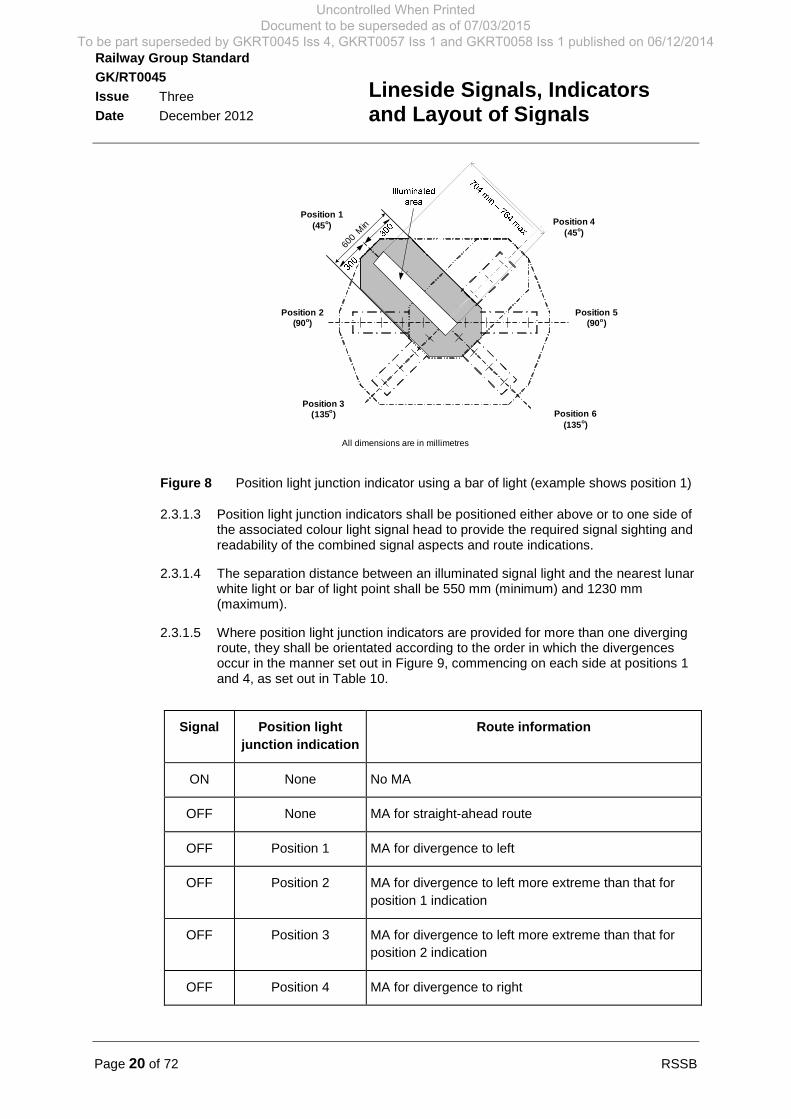
position 1) 19Figure 8 Position light junction indicator using a bar of light (example shows
position 1) 20Figure 9 Orientation of position light junction indications relative to diverging routes 21Figure 10 SPAD indicator 26Figure 11 Stop board 30Figure 12 Distant board 31Figure 13 Buffer beam: format and colour 32Figure 14 Example of a 3-aspect to 4-aspect transition using transition method 1 39Figure 15 Example of a 3-aspect to 4-aspect transition using transition method 2 39Figure 16 Example of a 3-aspect to 4-aspect transition using transition method 3 40Figure 17 Semaphore junction signal: examples of main signals displaying
stepped multiple semaphore arms 53Figure 18 Semaphore junction signal: examples of main signals displaying stacked
multiple semaphore arms 53
Uncontrolled When Printed Document to be superseded as of 07/03/2015
To be part superseded by GKRT0045 Iss 4, GKRT0057 Iss 1 and GKRT0058 Iss 1 published on 06/12/2014
RSSB Page 5 of 72
Railway Group Standard
GK/RT0045
Issue Three
Date December 2012
Lineside Signals, Indicatorsand Layout of Signals
Part 1 Purpose and Introduction
1.1 Purpose
1.1.1 The purpose of this document is to specify the parameters and application oflineside signalling equipment that is used to display information about movementauthorities, equipment status and required operations to infrastructure managersat stations and railway undertaking personnel. This document mandates therequirements for:
a) The format and presentation of signals and their displayed aspects.
b) The format and presentation of indicators and their displayed indications.
c) The permitted combinations of signals and indicators.
d) The criteria for positioning signals within the layout.
e) The permitted type(s) of lineside signal and their application constraints.
f) The permitted sequences of signal aspects and indications displayed todrivers.
g) The forms of signal identification necessary to support communication ofsafety related operational messages between train crew and signallers.
1.1.2 Parts 2, 3, 4, 5, 6, 7, 8 and 9 of this document are applicable to areas where trainmovements are controlled using lineside signalling.
1.1.3 Parts 2, 4 and 7 of this document include some requirements (set out in 2.4.5,2.4.6 and 7.1) applicable to areas where train movements are controlled usingthe European Rail Traffic Management System (ERTMS) Level 2 without linesidesignals. Where this is the case, the particular applicability to ERTMS is describedin the section heading and the applicable clause(s).
1.2 Introduction1.2.1 Background
1.2.1.1 Lineside signals and indicators are provided by the infrastructure manager whereit is necessary to display information about movement authorities, equipmentstatus and / or required operations to railway undertaking personnel, includingtrain crew (for example, drivers, shunters and guards) and station staff (forexample, train dispatchers).
1.2.1.2 Movement authority information displayed by lineside signalling equipmentincludes information about:
a) The extent of the movement authority issued by the signaller or groundframe operator (depicted by the sequence of signal aspects).
b) The route that is set and the destination (depicted by combinations of signalaspects and route indications).
1.2.1.3 At some locations, movement authority information is supplemented by additionalinformation relating to the train operation, typically:
a) Infrastructure equipment status (for example, locally monitored levelcrossings), and
Uncontrolled When Printed Document to be superseded as of 07/03/2015
To be part superseded by GKRT0045 Iss 4, GKRT0057 Iss 1 and GKRT0058 Iss 1 published on 06/12/2014

Page 6 of 72 RSSB
Railway Group Standard
GK/RT0045
Issue Three
Date December 2012
Lineside Signals, Indicatorsand Layout of Signals
b) Operational information (for example, ‘Close doors’).
1.2.1.4 Railway undertaking personnel are able to:
a) Understand the operational rules that are associated with the aspects andindications displayed by signalling equipment.
b) Understand the movement authorities issued by the infrastructure managerusing:
i) The sequence of displayed signal aspects and indications.
ii) Knowledge of the route and the geographical location.
iii) Knowledge of the required train movement.
c) Control the movement of trains within the limits of the movement authority.
d) Identify and report signal aspect and indication irregularities.
1.2.1.5 This document provides for infrastructure managers’ and railway undertakings’compatibility in terms of understanding the information conveyed by signalaspects and indications. Incompatibility is a causal factor of an operationalirregularity such as a signal passed at danger (SPAD).
1.2.2 Principles
1.2.2.1 The GE/RT8000 Rule Book sets out:
a) The operational meaning of signal aspects and indications displayed by theinfrastructure manager.
b) The rules for train driving, which include the requirement to control the speedof the train with respect to the aspects and indications displayed by signals.
c) The rules for shunting.
d) The rules for train dispatch.
e) The rules for reporting signalling system failures.
1.2.2.2 The lineside signalling equipment is compatible with the operating rules, so thatoperating personnel can correctly interpret the information displayed by thesignalling system.
1.2.2.3 The standard performance requirements applicable to lineside signals andindicators are specified, so that displayed aspects and indications are visible tothe driver.
1.2.2.4 The layout of signalling equipment is specified so that, when train movementstake place, drivers are given sufficient and appropriate movement authorityinformation.
1.2.3 Related requirements in other documents
1.2.3.1 The following Railway Group Standards contain requirements that are relevant tothe scope of this document:
GC/RT5021 Track System Requirements
GE/RT8000 Rule Book
Uncontrolled When Printed Document to be superseded as of 07/03/2015
To be part superseded by GKRT0045 Iss 4, GKRT0057 Iss 1 and GKRT0058 Iss 1 published on 06/12/2014
RSSB Page 7 of 72
Railway Group Standard
GK/RT0045
Issue Three
Date December 2012
Lineside Signals, Indicatorsand Layout of Signals
GE/RT8030 Requirements for a Train Protection and Warning System(TPWS)
GE/RT8035 Automatic Warning System
GE/RT8037 Signal Position and Visibility
GE/RT8071 Control Facilities for use during Lineside Signalling Failures
GK/RT0075 Lineside Signal Spacing and Speed Signage
GK/RT0044 Controls for Signalling a Train onto an Occupied Line
GO/RT3215 Requirements for the Weekly Operating Notice, PeriodicalOperating Notice and Sectional Appendix
1.2.4 Supporting documents
1.2.4.1 The following Railway Group documents support this Railway Group Standard:
GK/GN0645 Guidance on Lineside Signals, Indicators and Layout ofSignals
1.3 Approval and authorisation of this document
1.3.1 The content of this document was approved by Control Command and Signalling(CCS) Standards Committee on 13 September 2012.
1.3.2 This document was authorised by RSSB on 26 October 2012.
Uncontrolled When Printed Document to be superseded as of 07/03/2015
To be part superseded by GKRT0045 Iss 4, GKRT0057 Iss 1 and GKRT0058 Iss 1 published on 06/12/2014

Page 8 of 72 RSSB
Railway Group Standard
GK/RT0045
Issue Three
Date December 2012
Lineside Signals, Indicatorsand Layout of Signals
Part 2 Requirements for Signalling Equipment
2.1 Display of operational information using the signalling system
2.1.1 Signalled movement authorities shall:
a) Be displayed only by the lineside signals and route indicators set out in thisstandard (see 2.2, 2.3 and 2.5), except where lineside operational signs areused to display information about movement authorities in accordance withGK/RT0055, and
b) Be displayed only using the sequences and combinations of signal aspectsand indications set out in this standard (see Parts 3, 4, 5, 6, 7 and 8).
2.1.2 Signalling indications shall be displayed only by the lineside indicators set out inthis standard (see 2.4).
2.1.3 The observed colour of light emitted by lineside signals and indicators shallcomply with specified parameters (see Appendix A).
2.1.4 Lineside signal and indicator structures shall comply with specified parameters(see Appendix B).
2.1.5 Lineside signals shall be identified (see Part 9).
2.2 Specification of lineside signals2.2.1 Colour light signal
2.2.1.1 Colour light signals shall only display the signal aspects set out in Table 1.
Signal aspect(see Appendix A)
Description MA information Remarks
One signal redlight
RED End of MA For applicationrequirements see
3.1
One signal yellowlight
SINGLE YELLOW End of MA ahead For applicationrequirements see
4.1Two signal yellowlights displayed
vertically
DOUBLE YELLOW Approaching end ofMA
For applicationrequirements see
4.1One signal yellow
flashing lightFLASHING
SINGLE YELLOWDiverging route setat the next signal
For applicationrequirements see
5.2.3Two signal yellow
flashing lightsdisplayed vertically
FLASHINGDOUBLE YELLOW
Approaching adiverging junction
For applicationrequirements see
5.2.3One signal green
lightGREEN Line clear
Table 1 Colour light signal ON and OFF aspects
2.2.1.2 Colour light signals shall display the relevant signal aspect at all times, except:
a) For those signals that are configured as approach lit signals (see 4.1.8), and
Uncontrolled When Printed Document to be superseded as of 07/03/2015
To be part superseded by GKRT0045 Iss 4, GKRT0057 Iss 1 and GKRT0058 Iss 1 published on 06/12/2014
RSSB Page 9 of 72
Railway Group Standard
GK/RT0045
Issue Three
Date December 2012
Lineside Signals, Indicatorsand Layout of Signals
b) Where the signalling technology used incorporates self-testing functionalitythat requires a brief interruption of the displayed aspect at defined intervals,in which case each interruption shall not exceed 250 ms.
2.2.1.3 Except for splitting distant signals (see 2.2.2) and co-acting signals (see 2.2.3):
a) Each colour light signal shall display only one signal aspect at a time, and
b) No other combination of colour light signal lights shall be displayed by colourlight signals.
2.2.1.4 Colour light signal lights that are designed to flash shall comply with the followingcriteria:
a) Flash at a frequency of 60 (+/-10) cycles per minute.
b) Have a mark:space ratio that provides visibility of the signal light for 50% -66% of each flashing cycle when observed in accordance with the relevantstandard performance category (see Appendix C).
c) Flash in synchronism within the signal head when the flashing double yellowaspect is displayed.
d) Flash in synchronism throughout the primary and co-acting signal headswhen flashing aspects are displayed by co-acting signals.
2.2.1.5 Each colour light signal light shall have an apparent light source that:
a) Has a diameter of 210 mm (-10mm/+20 mm), and
b) Meets the colour requirements set out in Appendix A
2.2.1.6 Where the colour light signal head incorporates multiple signal light sources (forexample, to display a double yellow aspect), the two illuminated signal lightapertures shall be vertically aligned with a centre to centre separation of 510(+20/-10 mm).
2.2.1.7 Except where signal sighting can be consistently achieved without a backboard(for example, where a signal is positioned in a dark environment), a backboardshall be provided with each colour light signal (see Appendix C).
2.2.1.8 Where the backboard is incorporated into the signal head, it shall have thefollowing dimensions:
a) 300 mm (minimum) from the centre of the top signal light aperture to the topedge of the signal backboard.
b) 300 mm (minimum) from the centre of the signal light aperture to the left andright side edges of the signal backboard.
c) 180 mm (minimum) from the centre of the bottom signal light aperture to thebottom edge of the signal backboard.
2.2.1.9 Where a separate backboard is provided behind the signal head, it shall be ofsufficient size to appear no smaller than a signal head mounted backboard.
2.2.1.10 Long-range colour light signals shall comply with standard performancecategory 1 (see Appendix C).
Uncontrolled When Printed Document to be superseded as of 07/03/2015
To be part superseded by GKRT0045 Iss 4, GKRT0057 Iss 1 and GKRT0058 Iss 1 published on 06/12/2014
Page 10 of 72 RSSB
Railway Group Standard
GK/RT0045
Issue Three
Date December 2012
Lineside Signals, Indicatorsand Layout of Signals
2.2.1.11 Short-range colour light signals shall comply with standard performancecategory 2 (see Appendix C).
2.2.2 Colour light signal configured as a splitting distant signal
2.2.2.1 The application requirements for splitting distant signals are set out in 5.2.6.
2.2.2.2 Splitting distant signals shall incorporate two colour light signal heads (see 2.2.1),referred to as the primary head and the offset head.
2.2.2.3 The primary head and offset head shall:
a) Be mounted so that the horizontal separation between signal light centres inthe two signal heads is 600 mm – 900 mm, and
b) Be positioned and aligned so that horizontally displayed signal lights appearlevel to the train driver (see example in Figure 1).
2.2.2.4 The splitting distant signal shall be positioned so that the primary head is locatedas near as practicable to the driver’s line of sight, that is to say:
a) For signals mounted on the left-hand side of the line, the primary head shallbe mounted to the right-hand side of the offset head (see example inFigure 1), and
b) For signals mounted on the right-hand side of the line, the primary headshall be mounted to the left-hand side of the offset head.
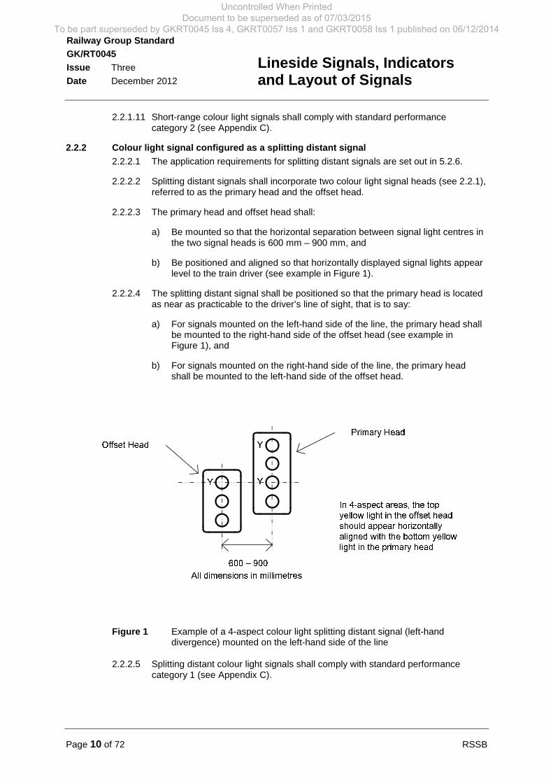
Figure 1 Example of a 4-aspect colour light splitting distant signal (left-handdivergence) mounted on the left-hand side of the line
2.2.2.5 Splitting distant colour light signals shall comply with standard performancecategory 1 (see Appendix C).
Uncontrolled When Printed Document to be superseded as of 07/03/2015
To be part superseded by GKRT0045 Iss 4, GKRT0057 Iss 1 and GKRT0058 Iss 1 published on 06/12/2014
RSSB Page 11 of 72
Railway Group Standard
GK/RT0045
Issue Three
Date December 2012
Lineside Signals, Indicatorsand Layout of Signals
2.2.3 Co-acting signals (colour light signal and semaphore signal)
2.2.3.1 Co-acting signals shall incorporate:
a) Primary signal and, where relevant, route indicator equipment that ispositioned to provide the required long-distance signal sighting andreadability, as set out in GE/RT8037, and
b) Co-acting signal and route indicator equipment that displays the same form(that is to say, colour light or semaphore) of signal aspect and routeindication as the primary equipment, and positioned to provide the requiredclose-up signal sighting and readability, as set out in GE/RT8037.
2.2.3.2 The primary and co-acting signal and route indicator equipment shall meet thesame standard performance requirements (see Appendix C), except where thereis insufficient space to provide compatible equipment, in which case:
a) The primary signal and route indicator equipment shall meet the appropriatestandard performance requirement compatible with the long-distance signalsighting and readability, and
b) The co-acting signal head and route indicator equipment shall meet thestandard performance requirement that is appropriate for close-up signalsighting and readability.
2.2.3.3 The same main signal aspect and route indication shall be displayed by theprimary and co-acting signals at all times.
2.2.3.4 The same subsidiary / shunting aspect and route indication shall be displayed bythe primary and co-acting signals at all times, except at signals where subsidiary /shunting aspects and route indications are omitted from the primary signal.
2.2.3.5 Subsidiary / shunting signal aspects and route indications shall only be omittedfrom the primary signal if the co-acting signal equipment, on its own, provides therequired sighting and readability for these aspects.
2.2.3.6 Signals shall only display movement authorities towards co-acting signals whenboth the primary and co-acting signals are detected to be displaying the correctsignal aspect, except when a failure of the second yellow light of a double yellowaspect in either the primary signal or co-acting signal means results in one signaldisplaying a more restrictive single yellow aspect in error.
2.2.4 Banner repeating signal
2.2.4.1 Banner repeating signals shall consist of a rectangular black or unlit bar,contrasted against a circular illuminated background.
2.2.4.2 2-state banner repeating signals shall comply with standard performancecategory 2 (see Appendix C), except at locations where the signal sighting andreadability requirement (as set out in GE/RT8037) is compatible with the use of astandard performance category 3 banner repeating signal (for example, in astation platform where all trains start from rest).
2.2.4.3 3-state banner repeating signals shall comply with (see Appendix C):
a) Standard performance category 1 in terms of distinguishing a green OFFaspect from a white OFF aspect, and
b) Standard performance category 2 in terms of readability of the white ON andwhite OFF aspect.
Uncontrolled When Printed Document to be superseded as of 07/03/2015
To be part superseded by GKRT0045 Iss 4, GKRT0057 Iss 1 and GKRT0058 Iss 1 published on 06/12/2014
Page 12 of 72 RSSB
Railway Group Standard
GK/RT0045
Issue Three
Date December 2012
Lineside Signals, Indicatorsand Layout of Signals
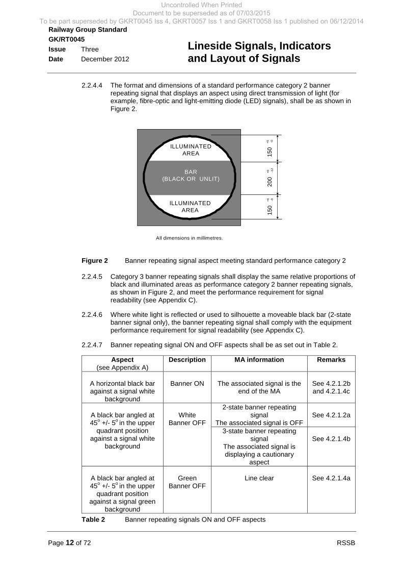
2.2.4.4 The format and dimensions of a standard performance category 2 bannerrepeating signal that displays an aspect using direct transmission of light (forexample, fibre-optic and light-emitting diode (LED) signals), shall be as shown inFigure 2.
20
0+
0 -12
150
+6 -0
15
0+
6 -0
ILLUMINATEDAREA
BAR(BLACK OR UNLIT)
ILLUMINATEDAREA
All dimensions in millimetres.
Figure 2 Banner repeating signal aspect meeting standard performance category 2
2.2.4.5 Category 3 banner repeating signals shall display the same relative proportions ofblack and illuminated areas as performance category 2 banner repeating signals,as shown in Figure 2, and meet the performance requirement for signalreadability (see Appendix C).
2.2.4.6 Where white light is reflected or used to silhouette a moveable black bar (2-statebanner signal only), the banner repeating signal shall comply with the equipmentperformance requirement for signal readability (see Appendix C).
2.2.4.7 Banner repeating signal ON and OFF aspects shall be as set out in Table 2.
Aspect(see Appendix A)
Description MA information Remarks
A horizontal black baragainst a signal white
background
Banner ON The associated signal is theend of the MA
See 4.2.1.2band 4.2.1.4c
A black bar angled at45
o+/- 5
oin the upper
quadrant positionagainst a signal white
background
WhiteBanner OFF
2-state banner repeatingsignal
The associated signal is OFFSee 4.2.1.2a
3-state banner repeatingsignal
The associated signal isdisplaying a cautionary
aspect
See 4.2.1.4b
A black bar angled at45
o+/- 5
oin the upper
quadrant positionagainst a signal green
background
GreenBanner OFF
Line clear See 4.2.1.4a
Table 2 Banner repeating signals ON and OFF aspects
Uncontrolled When Printed Document to be superseded as of 07/03/2015
To be part superseded by GKRT0045 Iss 4, GKRT0057 Iss 1 and GKRT0058 Iss 1 published on 06/12/2014

RSSB Page 13 of 72
Railway Group Standard
GK/RT0045
Issue Three
Date December 2012
Lineside Signals, Indicatorsand Layout of Signals
2.2.4.8 Splitting banner repeating signals shall incorporate two banner repeating signalheads.
2.2.4.9 The dimension between the centre of the two signal heads of a splitting bannerrepeating signal shall be:
a) 1000 mm (+/- 100 mm) in the horizontal plane, and
b) 500 mm (+/- 50 mm) in the vertical plane, except where there is no obviousstraight ahead route at the junction, in which case the two signal heads shallbe positioned at the same level.
2.2.5 Position light signal (including ERTMS level 2 fitted lines)
2.2.5.1 The requirements for provision of stop signals, including position light signals, areset out in 3.1.2.
2.2.5.2 Position light signals shall display ON and OFF aspects by means of the positionand colour of lights.
2.2.5.3 Independent position light signals shall only display one of the aspects set out inTable 3 at a time.
2.2.5.4 Independent position light signals that display the ON aspect using two yellowlights shall only be provided by exception and only as a direct replacement for anexisting semaphore yellow shunting disc signal or existing yellow/white positionlight signal.
Aspect Description MA information
Two signal red lightshorizontally displayed
ON End of MA
Two signal yellow lightshorizontally displayed
ON End of MA formovements travelling inthe direction(s) to whichthe signal can be cleared
Two lunar white lightsdisplayed at an upperquadrant angle of 45
oOFF Shunting MA
Two lunar white flashinglights displayed at an
upper quadrant angle of45
o
OFF Degraded MA
Table 3 Independent position light signals ON and OFF aspects
2.2.5.5 Position light signals associated with a colour light signal shall only display one ofthe aspects set out in Table 4 at a time.
Aspect Description MA information
No light displayed ON Obey colour light signalaspect
Two lunar white lightsdisplayed at an upper
quadrant angle of 45oin
association with a colourlight signal red aspect
OFF Permissive MA
(For calling-onmovements, the section
ahead is occupied)
Uncontrolled When Printed Document to be superseded as of 07/03/2015
To be part superseded by GKRT0045 Iss 4, GKRT0057 Iss 1 and GKRT0058 Iss 1 published on 06/12/2014
Page 14 of 72 RSSB
Railway Group Standard
GK/RT0045
Issue Three
Date December 2012
Lineside Signals, Indicatorsand Layout of Signals
Aspect Description MA information
Two lunar white flashinglights displayed at an
upper quadrant angle of45
owith or without a
colour light signal redaspect
OFF
Degraded MA
Table 4 Subsidiary position light signals associated with a colour light signal:ON and OFF aspects
2.2.5.6 Position light signals used to mark the limit of shunt for a movement in theopposite direction to the signalled flow of traffic shall continuously display the ONaspect set out in Table 5.
Aspect Description MA information
Two signal red lightshorizontally displayed
ON End of MA
Table 5 Independent position light signals (limit of shunt) aspect
2.2.5.7 Where independent position light signals that display the aspects set out in Table3 are to be added to an existing signalling layout that includes independentposition light signals that display a different form of ON aspect, the signallinglayout shall be designed so that:
a) Drivers will not observe the different forms of ON aspect at the same timeduring train movements, and
b) The transition between the different forms of ON aspect is clearly defined.
2.2.5.8 Position light signal aspects that are designed to flash shall:
a) Flash at a frequency of 60 (+/- 10) cycles per minute, and
b) Have a mark:space ratio that provides visibility of the signal light for 50% -66% of each flashing cycle when observed in accordance with standardperformance category 3 (see Appendix C).
2.2.5.9 Position light signals shall comply with standard performance category 3 (seeAppendix C).
2.2.6 Semaphore main stop signal and distant signal
2.2.6.1 Semaphore main stop signals shall display aspects by means of a rectangularsemaphore signal arm and coloured lights.
2.2.6.2 Semaphore main stop signals shall comply with standard performance category 4(see Appendix C), except where a signal is provided to authorise trainmovements from a goods line or siding(s) onto a passenger line. In such casesthe semaphore main stop signal shall comply with either standard performancecategory 4 or standard performance category 2, whichever is appropriate for thesignal sighting and readability requirement.
2.2.6.3 The colour, format and dimensions of semaphore main stop signal arms meetingperformance category 4 shall be as shown in Figure 3.
Uncontrolled When Printed Document to be superseded as of 07/03/2015
To be part superseded by GKRT0045 Iss 4, GKRT0057 Iss 1 and GKRT0058 Iss 1 published on 06/12/2014
RSSB Page 15 of 72
Railway Group Standard
GK/RT0045
Issue Three
Date December 2012
Lineside Signals, Indicatorsand Layout of Signals
2.2.6.4 The dimensions of semaphore main stop signal arms meeting performancecategory 2 shall be as set out in 2.2.8 and as shown in Figure 6, except where alarger standard performance category 2 signal arm is provided to maintainconsistency with an existing signalling layout.
SIGNALPOSTEND
SIGNALPOSTEND
BACK VIEW
FRONT VIEW
RED BS 381C shade 537
BLACK
WHITE
178 mm 318 mm
178 mm318 mm
1060 mm
26
0m
m
Tolerance on all dimensions: ± 5%
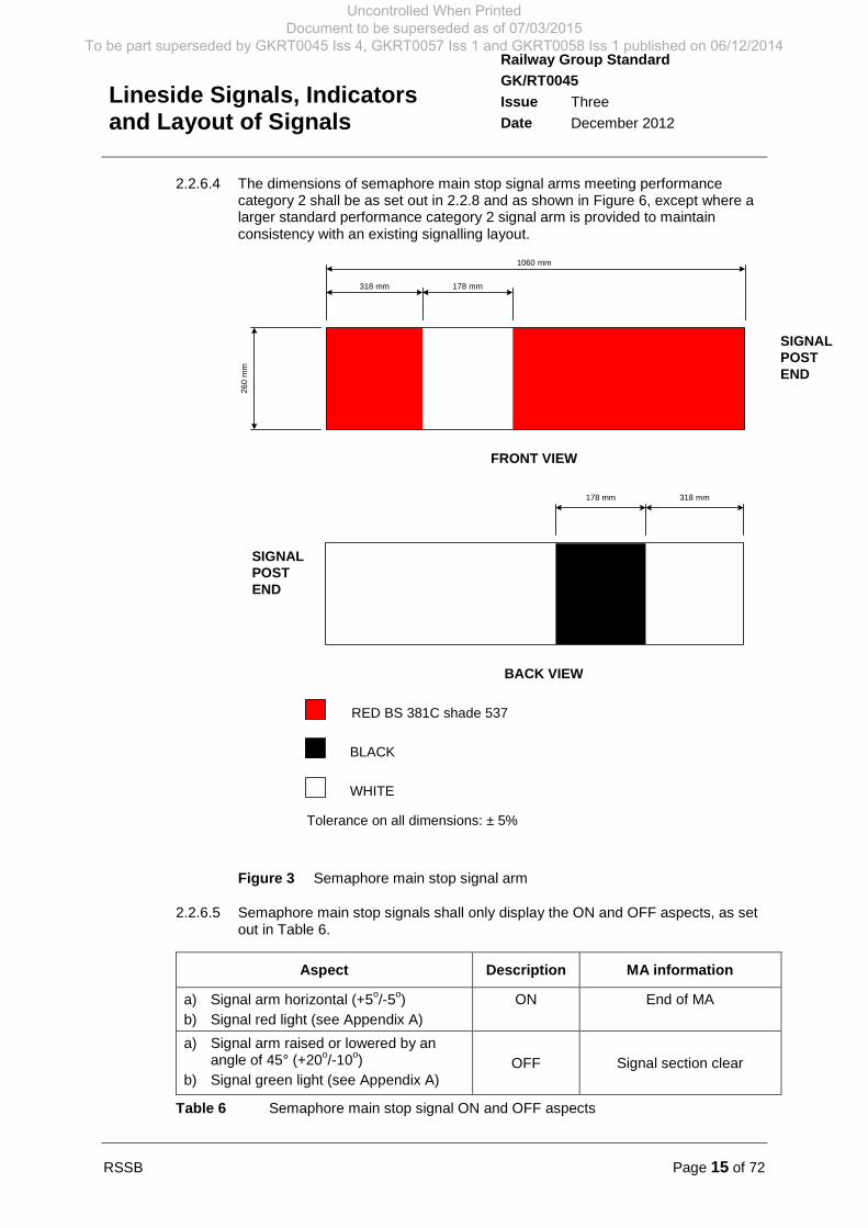
Figure 3 Semaphore main stop signal arm
2.2.6.5 Semaphore main stop signals shall only display the ON and OFF aspects, as setout in Table 6.
Aspect Description MA information
a) Signal arm horizontal (+5o/-5
o)
b) Signal red light (see Appendix A)
ON End of MA
a) Signal arm raised or lowered by anangle of 45° (+20
o/-10
o)
b) Signal green light (see Appendix A)OFF Signal section clear
Table 6 Semaphore main stop signal ON and OFF aspects
Uncontrolled When Printed Document to be superseded as of 07/03/2015
To be part superseded by GKRT0045 Iss 4, GKRT0057 Iss 1 and GKRT0058 Iss 1 published on 06/12/2014
Page 16 of 72 RSSB
Railway Group Standard
GK/RT0045
Issue Three
Date December 2012
Lineside Signals, Indicatorsand Layout of Signals
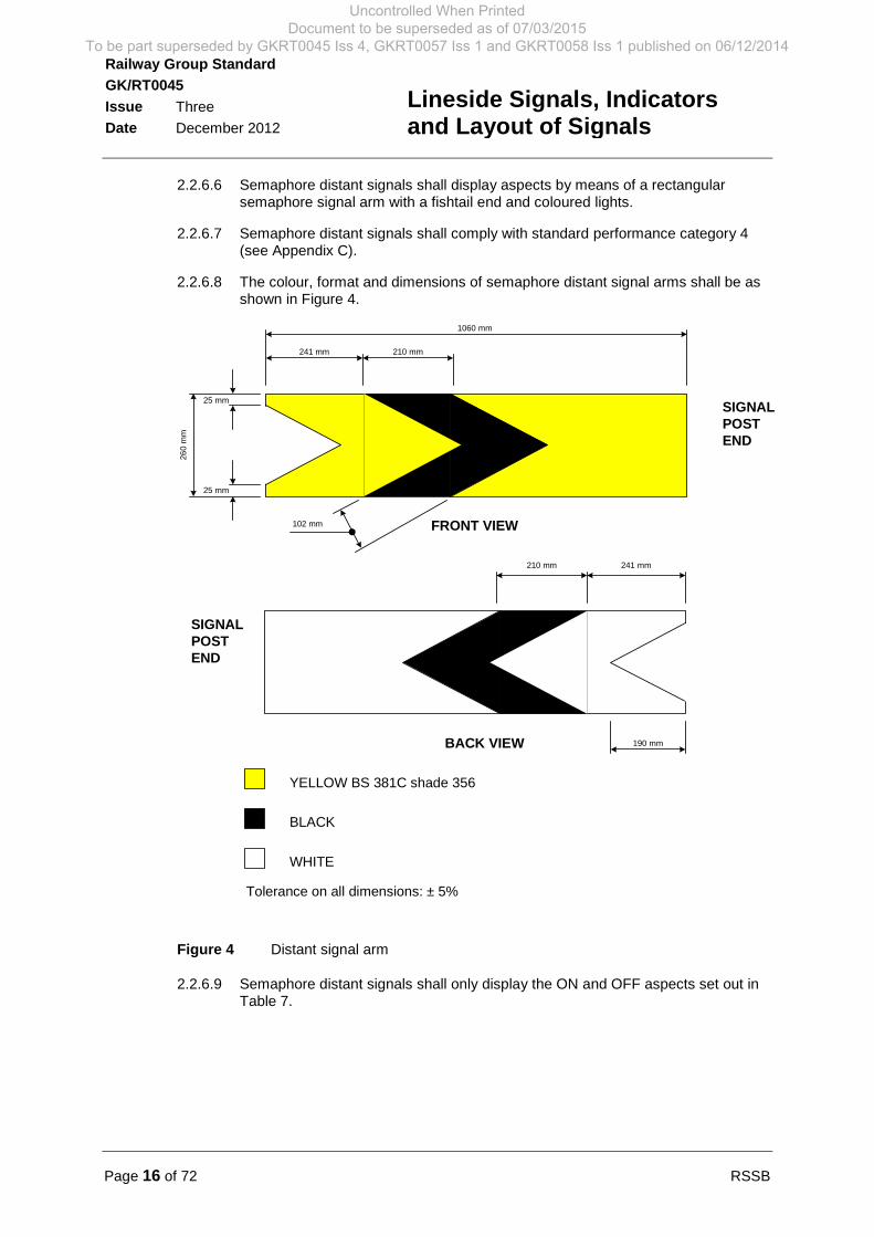
2.2.6.6 Semaphore distant signals shall display aspects by means of a rectangularsemaphore signal arm with a fishtail end and coloured lights.
2.2.6.7 Semaphore distant signals shall comply with standard performance category 4(see Appendix C).
2.2.6.8 The colour, format and dimensions of semaphore distant signal arms shall be asshown in Figure 4.
SIGNALPOSTEND
SIGNALPOSTEND
BACK VIEW
FRONT VIEW
YELLOW BS 381C shade 356
BLACK
WHITE
210 mm 241 mm
190 mm
210 mm241 mm
1060 mm
102 mm
25 mm
25 mm
26
0m
m
Tolerance on all dimensions: ± 5%
Figure 4 Distant signal arm
2.2.6.9 Semaphore distant signals shall only display the ON and OFF aspects set out inTable 7.
Uncontrolled When Printed Document to be superseded as of 07/03/2015
To be part superseded by GKRT0045 Iss 4, GKRT0057 Iss 1 and GKRT0058 Iss 1 published on 06/12/2014
RSSB Page 17 of 72
Railway Group Standard
GK/RT0045
Issue Three
Date December 2012
Lineside Signals, Indicatorsand Layout of Signals
Aspect Description MA information
a) Signal arm horizontal (+5o/-5o)
b) Signal red light (see Appendix A)
ON End of MA ahead
c) Signal arm raised or lowered by anangle of 45° (+20
o/-10
o)
d) Signal green light (see Appendix A)
OFF
Line clear
(see 4.1.6.1b)
Table 7 Semaphore distant signal ON and OFF aspects
2.2.7 Semaphore subsidiary signal
2.2.7.1 Semaphore subsidiary signals shall be provided in accordance with GK/RT0044.
2.2.7.2 Semaphore subsidiary signals shall display aspects by means of a rectangularsemaphore signal arm, and coloured lights, positioned below the main arm of thesemaphore stop signal that it is associated with and on the same signal post.
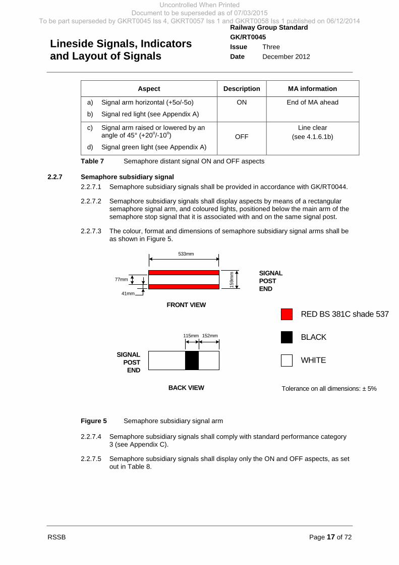
2.2.7.3 The colour, format and dimensions of semaphore subsidiary signal arms shall beas shown in Figure 5.
RED BS 381C shade 537
BLACK
WHITESIGNAL
POSTEND
BACK VIEW
FRONT VIEW
115mm 152mm
SIGNALPOSTEND
533mm
15
9m
m
41mm
77mm
Tolerance on all dimensions: ± 5%
Figure 5 Semaphore subsidiary signal arm
2.2.7.4 Semaphore subsidiary signals shall comply with standard performance category3 (see Appendix C).
2.2.7.5 Semaphore subsidiary signals shall display only the ON and OFF aspects, as setout in Table 8.
Uncontrolled When Printed Document to be superseded as of 07/03/2015
To be part superseded by GKRT0045 Iss 4, GKRT0057 Iss 1 and GKRT0058 Iss 1 published on 06/12/2014
Page 18 of 72 RSSB
Railway Group Standard
GK/RT0045
Issue Three
Date December 2012
Lineside Signals, Indicatorsand Layout of Signals
Aspect Description MA information
a) Signal arm horizontal (+5o/-5
o)
b) Signal red light (see Appendix A)
ON Obey associated semaphorestop signal
a) Arm raised or lowered by angle of45° (+20
o/-10
o)
b) Signal green light (see Appendix A)OFF Permissive MA
Table 8 Semaphore subsidiary signal ON and OFF aspects
2.2.8 Semaphore shunting signal
2.2.8.1 Semaphore shunting signals shall be provided in accordance with 3.1.2.
2.2.8.2 Semaphore shunting signals shall display aspects using either one of thefollowing:
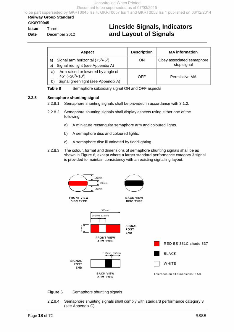
a) A miniature rectangular semaphore arm and coloured lights.
b) A semaphore disc and coloured lights.
c) A semaphore disc illuminated by floodlighting.
2.2.8.3 The colour, format and dimensions of semaphore shunting signals shall be asshown in Figure 6, except where a larger standard performance category 3 signalis provided to maintain consistency with an existing signalling layout.
RED BS 381C shade 537
BLACK
WHITESIGNAL
POSTEND
BACK VIEWARM TYPE
115mm 152mm
FRONT VIEWARM TYPE
SIGNALPOSTEND
115mm152mm
533mm
15
9m
m
146mm
102mm
BACK VIEWDISC TYPE
FRONT VIEWDISC TYPE
Tolerance on all dimensions: ± 5%
146mm
Figure 6 Semaphore shunting signals
2.2.8.4 Semaphore shunting signals shall comply with standard performance category 3(see Appendix C).
Uncontrolled When Printed Document to be superseded as of 07/03/2015
To be part superseded by GKRT0045 Iss 4, GKRT0057 Iss 1 and GKRT0058 Iss 1 published on 06/12/2014

RSSB Page 19 of 72
Railway Group Standard
GK/RT0045
Issue Three
Date December 2012
Lineside Signals, Indicatorsand Layout of Signals
2.2.8.5 Semaphore shunting signals shall display only the ON and OFF aspects, as setout in Table 9.
#1 Not required where a semaphore disc is illuminated by floodlighting
Table 9 Semaphore shunting signal ON and OFF aspects
2.3 Specification of route indicators2.3.1 Position light junction indicator
2.3.1.1 Position light junction indicators shall only be provided in association with colourlight signals (see 5.1.1).
2.3.1.2 Position light junction indicators shall display the indication of route by means ofeither:
a) A line of five lunar white light points (see Appendix A) orientated as shown inFigure 7, or
b) A bar of light, as shown in Figure 8.
Position 2(90o)
Position 1(45o)
All dimensions are in millimetres
764M
ax. 704M
in
between
centreline
oflenses
176Min
Position 3(135o)
Position 4(45o)
Position 5(90o)
Position 6(135o)
600
Min
Figure 7 Position light junction indicator using five lunar white lights (example showsposition 1)
Aspect Description MA information
a) Disc with red bar horizontal (+5o/-5
o) or
Red and white horizontal (+5o/-5
o) arm
b) Signal red light displayed (see Appendix A) #1
ON End of MA
a) Disc turned 45° (+20o/-10
o) or
Arm raised or lowered by angle of 45° (+20o/-10
o)
b) Signal green light displayed (see Appendix A) #1
OFF Shunting MA
Uncontrolled When Printed Document to be superseded as of 07/03/2015
To be part superseded by GKRT0045 Iss 4, GKRT0057 Iss 1 and GKRT0058 Iss 1 published on 06/12/2014
Page 20 of 72 RSSB
Railway Group Standard
GK/RT0045
Issue Three
Date December 2012
Lineside Signals, Indicatorsand Layout of Signals
Position 2(90o)
Position 1(45o)
All dimensions are in millimetres
176Min
Position 3(135
o)
Position 4(45o)
Position 5(90o)
Position 6
(135o)
600
Min
Figure 8 Position light junction indicator using a bar of light (example shows position 1)
2.3.1.3 Position light junction indicators shall be positioned either above or to one side ofthe associated colour light signal head to provide the required signal sighting andreadability of the combined signal aspects and route indications.
2.3.1.4 The separation distance between an illuminated signal light and the nearest lunarwhite light or bar of light point shall be 550 mm (minimum) and 1230 mm(maximum).
2.3.1.5 Where position light junction indicators are provided for more than one divergingroute, they shall be orientated according to the order in which the divergencesoccur in the manner set out in Figure 9, commencing on each side at positions 1and 4, as set out in Table 10.
Signal Position light
junction indication
Route information
ON None No MA
OFF None MA for straight-ahead route
OFF Position 1 MA for divergence to left
OFF Position 2 MA for divergence to left more extreme than that for
position 1 indication
OFF Position 3 MA for divergence to left more extreme than that for
position 2 indication
OFF Position 4 MA for divergence to right
Uncontrolled When Printed Document to be superseded as of 07/03/2015
To be part superseded by GKRT0045 Iss 4, GKRT0057 Iss 1 and GKRT0058 Iss 1 published on 06/12/2014

RSSB Page 21 of 72
Railway Group Standard
GK/RT0045
Issue Three
Date December 2012
Lineside Signals, Indicatorsand Layout of Signals
Table 10 Position light junction indicator: displayed route indications
NO INDICATIONPOSITION 4POSITION 5POSITION 6
POSITION 3POSITION 2POSITION 1NO INDICATION
Figure 9 Orientation of position light junction indications relative to diverging routes
2.3.1.6 Position light junction indicators shall comply with standard performance category1 (see Appendix C).
2.3.2 Alphanumeric route indicator (including ERTMS level 2 operated lines)
2.3.2.1 The requirements for provision of route indicators at junction signals are set out in5.1.1.
2.3.2.2 Alphanumeric route indicators shall display the indication of route in the form ofan illuminated alphanumeric display, coloured signal white.
2.3.2.3 The alphanumeric character font shall approximate to Gill Sans light.
2.3.2.4 Alphanumeric route indicators shall display the indication of route using one ormore of the following characters:
1 2 3 4 5 6 7 8 9 0
A B C D E F G H K L M N O P R S T U V W X Y Z
2.3.2.5 The following limitations on the form of alphanumeric indications shall be applied:
a) ‘O’ and ‘V’ shall only be used in combination with other letters where it isnecessary to describe a geographic meaning.
b) When used in conjunction with a subsidiary signal, ‘C’ and ‘S’ shall bereserved for indicating the class of movement.
Signal Position light
junction indication
Route information
OFF Position 5 MA for divergence to right more extreme than that for
position 4 indication
OFF Position 6 MA for divergence to right more extreme than that for
position 5 indication
Uncontrolled When Printed Document to be superseded as of 07/03/2015
To be part superseded by GKRT0045 Iss 4, GKRT0057 Iss 1 and GKRT0058 Iss 1 published on 06/12/2014
Page 22 of 72 RSSB
Railway Group Standard
GK/RT0045
Issue Three
Date December 2012
Lineside Signals, Indicatorsand Layout of Signals
c) An alphanumeric route indication incorporating the letter ‘X’ shall only bedisplayed in combination with main or shunting signal OFF aspects when theroute is set towards a ‘limit of shunt’, or along a bi-directional line in theopposite direction to the normal flow of traffic. Where more than one suchroute exists, the ‘X’ indication shall be qualified by a reference to the lineconcerned.
d) Combinations ‘BU’, ‘CD’, ‘RA’ and ‘OFF’ shall not be used.
2.3.2.6 Where an alphanumeric indication uses more than one character, the minimumdistance between the outermost points on adjacent characters shall be 20% ofcharacter height.
2.3.2.7 Standard alphanumeric route indicators shall comply with standard performancecategory 2 (see Appendix C).
2.3.2.8 Miniature alphanumeric route indicators shall comply with standard performancecategory 3 (see Appendix C).
2.3.3 Preliminary route indicator
2.3.3.1 The requirements for provision of preliminary route indicators are set out in 5.1.4.
2.3.3.2 The displayed preliminary route indication shall be displayed in the form of asignal white illuminated arrow against a black background, as set out in Table 11.
Indication Route information Indication Route information
No indication
Junction signal isdisplaying the ONaspect
Position 0
Junction signal isdisplaying an OFFaspect for thestraight-ahead route
Position 1
Junction signal isdisplaying an OFFaspect for adivergence to the left
Position 4
Junction signal isdisplaying an OFFaspect for adivergence to theright
Position 2
Junction signal isdisplaying an OFFaspect for adivergence to the leftmore extreme thanposition 1
Position 5
Junction signal isdisplaying an OFFaspect for adivergence to theright more extremethan position 4
Uncontrolled When Printed Document to be superseded as of 07/03/2015
To be part superseded by GKRT0045 Iss 4, GKRT0057 Iss 1 and GKRT0058 Iss 1 published on 06/12/2014
RSSB Page 23 of 72
Railway Group Standard
GK/RT0045
Issue Three
Date December 2012
Lineside Signals, Indicatorsand Layout of Signals
Indication Route information Indication Route information
Position 3
Junction signal isdisplaying an OFFaspect for adivergence to the leftmore extreme thanposition 2
Position 6
Junction signal isdisplaying an OFFaspect for adivergence to theright more extremethan position 5
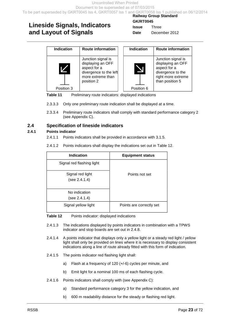
Table 11 Preliminary route indicators: displayed indications
2.3.3.3 Only one preliminary route indication shall be displayed at a time.
2.3.3.4 Preliminary route indicators shall comply with standard performance category 2(see Appendix C).
2.4 Specification of lineside indicators2.4.1 Points indicator
2.4.1.1 Points indicators shall be provided in accordance with 3.1.5.
2.4.1.2 Points indicators shall display the indications set out in Table 12.
Indication Equipment status
Signal red flashing light
Points not setSignal red light
(see 2.4.1.4)
No indication
(see 2.4.1.4)
Signal yellow light Points are correctly set
Table 12 Points indicator: displayed indications
2.4.1.3 The indications displayed by points indicators in combination with a TPWSindicator and stop boards are set out in 2.4.8.
2.4.1.4 A points indicator that displays only a yellow light or a steady red light / yellowlight shall only be provided on lines where it is necessary to display consistentindications along a line of route already fitted with this form of indication.
2.4.1.5 The points indicator red flashing light shall:
a) Flash at a frequency of 120 (+/-6) cycles per minute, and
b) Emit light for a nominal 100 ms of each flashing cycle.
2.4.1.6 Points indicators shall comply with (see Appendix C):
a) Standard performance category 3 for the yellow indication, and
b) 600 m readability distance for the steady or flashing red light.
Uncontrolled When Printed Document to be superseded as of 07/03/2015
To be part superseded by GKRT0045 Iss 4, GKRT0057 Iss 1 and GKRT0058 Iss 1 published on 06/12/2014
Page 24 of 72 RSSB
Railway Group Standard
GK/RT0045
Issue Three
Date December 2012
Lineside Signals, Indicatorsand Layout of Signals
2.4.2 Driver’s level crossing indicator (including ERTMS operated lines)
2.4.2.1 The requirements for provision of driver’s level crossing indicators are set out inGK/RT0192.
2.4.2.2 Drivers’ level crossing indicators shall display the indications set out in Table 13.
Table 13 Driver’s level crossing indicator: displayed indications
2.4.2.3 The indications displayed by drivers’ level crossing indicators associated with aTPWS indicator at a stop board are set out in 2.4.8.
2.4.2.4 The driver’s level crossing indicator red flashing light shall:
a) Flash at a frequency of 120 (+/-6) cycles per minute, and
b) Emit light for a nominal 100 ms of each flashing cycle.
2.4.2.5 The driver’s level crossing indicator white flashing light shall:
a) Flash at a frequency of 60 (min) to 90 (max) cycles per minute, and
b) Have a mark:space ratio that provides visibility of the signal light for 50% -66% of each flashing cycle when observed in accordance with standardperformance category 1 (see Appendix C).
2.4.2.6 Drivers’ level crossing indicators shall comply with:
a) Standard performance category 1 for the white flashing light, and
b) 600 m readability distance for the red flashing light (see Appendix C).
2.4.3 Loading / unloading indicator
2.4.3.1 The requirements for provision of loading / unloading indicators are set out in3.1.6.
2.4.3.2 Loading / unloading indicators shall display the indications set out in Table 14.
Indication MA information Indication MA information
One signal whitelight between twosignal red lights
The operatorrequires the trainto stop
Three whitelights vertically
aligned
The operatorrequires the train tomove slowly in thenormal direction forloading or unloading
Indication Equipment status Remarks
Signal red flashing light Level crossing equipment is notoperating correctly
Not provided where the levelcrossing indication is
displayed at a stop board(see 2.4.8)
Signal white flashinglight
Level crossing equipment iscorrectly operating
Uncontrolled When Printed Document to be superseded as of 07/03/2015
To be part superseded by GKRT0045 Iss 4, GKRT0057 Iss 1 and GKRT0058 Iss 1 published on 06/12/2014
RSSB Page 25 of 72
Railway Group Standard
GK/RT0045
Issue Three
Date December 2012
Lineside Signals, Indicatorsand Layout of Signals
Indication MA information Indication MA information
Three white lightsangled at 45
oto
horizontal
The operatorrequires the trainto prepare to stop
Three flashingwhite lights
angled at 45o
tohorizontal
The operatorrequires the train tomove slowly in theopposite direction tothat required forloading or unloading
No displayedindication
Indicators are notin use
Table 14 Loading / unloading indicator: displayed indications
2.4.3.3 Each loading / unloading indicator shall display only one of the permittedindications at a time.
2.4.3.4 The loading / unloading indicator flashing aspect shall:
a) Flash at a frequency of 60 (+/-10) cycles per minute, and
b) Have a mark:space ratio that provides visibility of the signal light for 50% -66% of each flashing cycle when observed in accordance with standardperformance category 3 (see Appendix C).
2.4.3.5 Loading / unloading indicators shall comply with standard performance category 3(see Appendix C).
2.4.4 SPAD indicator
2.4.4.1 SPAD indicators shall only be provided as a means of mitigating theconsequence of a signal passed at danger (SPAD) (see GI/RT7006).
2.4.4.2 SPAD indicators shall display the indications set out in Table 15.
Indication Description MA information
One steady signal red lightvertically aligned between two
signal red flashing lights
The signal to which theSPAD indicator applies
has been passedwithout authority
Train has passed the endof movement authority
No indication No SPAD detected No SPAD detected
Table 15 SPAD indicator: displayed indications
Uncontrolled When Printed Document to be superseded as of 07/03/2015
To be part superseded by GKRT0045 Iss 4, GKRT0057 Iss 1 and GKRT0058 Iss 1 published on 06/12/2014
Page 26 of 72 RSSB
Railway Group Standard
GK/RT0045
Issue Three
Date December 2012
Lineside Signals, Indicatorsand Layout of Signals
2.4.4.3 The two flashing red lamps shall:
a) Flash in synchronism at a frequency of 60 (+/-10) cycles per minute, and
b) Have a mark:space ratio that provides visibility of the illuminated indicationfor 50% - 66% of each flashing cycle when observed by a driver.
2.4.4.4 The SPAD indicator assembly shall comply with the format and dimensionsshown in Figure 10.
2.4.4.5 SPAD indicators shall comply with standard performance category 2 and becapable of attracting the driver’s attention:
a) When it is on the periphery of a driver’s vision at angles to the centre line of30
o.
b) At a distance of 100 m.
c) In an environment with other bright background lights.
Figure 10 SPAD indicator
2.4.4.6 Where provided, SPAD indicators shall be positioned and aligned so that driversapproaching the point of conflict have a clear view of the indicator and have thegreatest opportunity of stopping the train before the point of conflict is reached.
2.4.5 OFF indicator (including ERTMS level 2 operated lines)
2.4.5.1 OFF indicators shall be provided at stations in accordance with GE/RT8060.
2.4.5.2 OFF indicators shall only display the indications set out in Table 16.
Uncontrolled When Printed Document to be superseded as of 07/03/2015
To be part superseded by GKRT0045 Iss 4, GKRT0057 Iss 1 and GKRT0058 Iss 1 published on 06/12/2014
RSSB Page 27 of 72
Railway Group Standard
GK/RT0045
Issue Three
Date December 2012
Lineside Signals, Indicatorsand Layout of Signals
Indication Operational information
Associated signal is displaying an ON aspect
Associated signal is displaying an OFFaspect
The associated up direction signal isdisplaying an OFF aspect
The associated down direction signal isdisplaying an OFF aspect
Table 16 OFF indicator: displayed indications
2.4.5.3 The illuminated OFF indication shall be coloured signal white.
2.4.5.4 The character font shall approximate to Gill Sans light.
2.4.5.5 Where lineside signals are provided, an OFF indicator shall display the relevantOFF indication only when the signal(s) to which it applies is displaying an OFFaspect. No indication shall be displayed at all other times.
2.4.5.6 In ERTMS operated areas, an OFF indicator shall display 'OFF' only when a trainhas confirmed that it has received an in-cab movement authority to pass the nodeto which the OFF indicator applies. No indication shall be displayed at all othertimes.
2.4.5.7 OFF indicators shall comply with standard performance category 5 (seeAppendix C).
2.4.6 CD indicator and RA Indicator (including ERTMS level 2 operated lines)
2.4.6.1 CD and RA indicators shall be provided at stations in accordance withGE/RT8060.
2.4.6.2 A self-restoring, secure operating device shall be provided for use by traindispatchers.
2.4.6.3 The indicator shall display the relevant indication only when the associatedcontrol device has been operated.
2.4.6.4 In ERTMS operated areas, a right away indicator shall display 'RA' only when atrain has confirmed that it has received an in-cab movement authority to pass thenode to which the right away indicator applies.
2.4.6.5 CD and RA indicators shall only display the relevant indications set out inTable 17.
Indication Operational information
Station operations are not complete
CLOSE DOORS
RIGHT AWAY
Table 17 CD and RA indicators: displayed indications
OF
UP OFF
OFFDN
CD
RA
Uncontrolled When Printed Document to be superseded as of 07/03/2015
To be part superseded by GKRT0045 Iss 4, GKRT0057 Iss 1 and GKRT0058 Iss 1 published on 06/12/2014

Page 28 of 72 RSSB
Railway Group Standard
GK/RT0045
Issue Three
Date December 2012
Lineside Signals, Indicatorsand Layout of Signals
2.4.6.6 Where a CD indicator is provided in conjunction with an RA indicator, the ‘RA’indication shall supersede the ‘CD’ indication.
2.4.6.7 The illuminated indication shall be coloured signal white.
2.4.6.8 The character font shall approximate to Gill Sans light.
2.4.6.9 CD indicators and RA indicators shall comply with standard performancecategory 5 (see Appendix C).
2.4.7 BU indicator
2.4.7.1 BU indicators shall be provided in accordance with GK/RT0192.
2.4.7.2 Where provided, BU indicators shall be positioned at a distance beyond the levelcrossing, so that the ‘BU’ indication is displayed before the front of the train thathas passed over the level crossing passes the BU indicator.
2.4.7.3 BU indicators shall only display the indications set out in Table 18.
Indication Equipment status information
The level crossing opening sequence hasnot operated
BARRIERS UP
Table 18 BU indicators: displayed indications
2.4.7.4 BU indicators shall display ‘BU’ only when the associated level crossing barriersare fully raised. No indication shall be displayed at all other times.
2.4.7.5 The illuminated indication shall be coloured signal white.
2.4.7.6 The character font shall approximate to Gill Sans light.
2.4.7.7 BU indicators shall comply with standard performance category 5 (seeAppendix C).
2.4.8 Train Protection and Warning System (TPWS) indicator
2.4.8.1 Where a TPWS indicator is required at a stop board, it shall be positioned either:
a) Underneath the relevant stop board so that it is readable from the drivingcab, or
b) Remotely from the stop board; only where drivers are required to leave thedriving cab to operate signalling equipment (for example, associated withdriver operated token exchange equipment).
2.4.8.2 TPWS indicators shall only display the indications set out in Table 19.
Indication Equipment status information
Steady signal blue light
#1
TPWS intervention set
Flashing signal blue light TPWS disarmed
No indication TPWS failed
#1 Normal state when no train is present
Table 19 TPWS indications
BU
Uncontrolled When Printed Document to be superseded as of 07/03/2015
To be part superseded by GKRT0045 Iss 4, GKRT0057 Iss 1 and GKRT0058 Iss 1 published on 06/12/2014

RSSB Page 29 of 72
Railway Group Standard
GK/RT0045
Issue Three
Date December 2012
Lineside Signals, Indicatorsand Layout of Signals
2.4.8.3 The TPWS indicator blue flashing light shall:
a) Flash at a frequency of 120 (+/-6) cycles per minute, and
b) Emit light for a nominal 100 ms of each flashing cycle.
2.4.8.4 TPWS indicators shall comply with standard performance category 3 (seeAppendix C).
2.4.8.5 Where a TPWS indicator at a stop board is combined with a points indicator (forexample, at the exit of a passing loop on a single line operated using the no-signaller token remote block system), the points indicator shall be positioned nextto the TPWS indicator, so that the points indication is closest to the driver’s line ofsight.
2.4.8.6 Where a TPWS indicator at a stop board is associated with a points indicator anda driver’s level crossing indicator:
a) The points indicator shall be positioned next to the TPWS indicator, so thatthe points indication is closest to the driver’s line of sight, and
b) The driver’s level crossing indicator shall be positioned adjacent to the stopboard separately from the points / TPWS indication so that concurrentlydisplayed indications are both readable as separate indications.
2.4.8.7 Where a TPWS indication is associated with a points indicator and / or a levelcrossing indicator:
a) The combinations of displayed indications shall comply with Table 20, and
b) The indications shall be consistently displayed in a logical sequence at eachlocation along a line of route.
TPWSindicator
Pointsindicator
LC indicator Equipment status information
Steady blue(#1)
No indication No indication TPWS intervention set
LC not operating
Steady blue(#1)
No indication Flashingwhite
TPWS intervention set
LC correctly operating
No indication Flashing red No indication Points not set (or pointsmoving)
LC not operating
Flashing blue No indication No indication TPWS disarmed
LC not operating
Flashing blue No indication Flashingwhite
TPWS disarmed
LC correctly operating
No indication Flashing red Flashingwhite
Points not set (points moving)
LC correctly operating
Uncontrolled When Printed Document to be superseded as of 07/03/2015
To be part superseded by GKRT0045 Iss 4, GKRT0057 Iss 1 and GKRT0058 Iss 1 published on 06/12/2014
Page 30 of 72 RSSB
Railway Group Standard
GK/RT0045
Issue Three
Date December 2012
Lineside Signals, Indicatorsand Layout of Signals
TPWSindicator
Pointsindicator
LC indicator Equipment status information
No indication No indication No indication TPWS failed
LC not operating
No indication No indication Flashingwhite
TPWS failed
LC correctly operating
#1 Normal state when no train is present
Table 20 Permitted combinations of TPWS, points and / or LC indications
2.5 Specification of lineside signs and buffer stops used as signals2.5.1 Stop board (including ERTMS level 2 operated lines)
2.5.1.1 Stop boards shall display a fixed stop aspect and written instructions statingeither:
a) The action to be taken by the train crew after stopping, or
b) The conditions for passing the stop board without stopping (for example,possession of the relevant long section token on a single line).
2.5.1.2 The wording displayed on each stop board shall be determined using the processfor assessment of compatibility set out in GE/RT8270.
2.5.1.3 The colours and dimensions of stop boards shall comply with Figure 11 andTable 21.
2.5.1.4 Reflectivity performance shall be no worse than that associated with Class R2retro-reflective material (as defined in BS EN 12899-1).
2.5.1.5 The font for wording on the sign shall be the same as for road signs as specifiedby the Transport Medium Alphabet (drawings TM1 and TM2) of the Traffic Signsand Signals Guidance published by the Department for Transport.
Notes:
1. RED BS4800 – 04E53
BLACK
WHITE
2. Colour of backof sign (includingstiffening): grey.
3. Dimensionsmay vary 5%.
4. Wording on lowerpart of sign mayvary as required forspecific application.
StopWhistle beforeproceeding
m m
b
n
l
n
i
a
c c c
d
e
f
g
h
j
k
k
c
Figure 11 Stop board
Uncontrolled When Printed Document to be superseded as of 07/03/2015
To be part superseded by GKRT0045 Iss 4, GKRT0057 Iss 1 and GKRT0058 Iss 1 published on 06/12/2014

RSSB Page 31 of 72
Railway Group Standard
GK/RT0045
Issue Three
Date December 2012
Lineside Signals, Indicatorsand Layout of Signals
a b c d e f g h i j k l m n
LargeBoard
1650
(min)
900 10 120 500 120 180 150 20 540
(min)
65 65 130
(min)
130
MediumBoard
1300
(min)
700 10 100 400 100 140 120 20 400
(min)
50 50 100
(min)
100
SmallBoard
700
(min)
400 5 55 220 50 80 65 10 210
(min)
30 30 60
(min)
60
(min)
(All dimensions in millimetres)
Table 21 Stop board: permitted dimensions
2.5.2 Distant board
2.5.2.1 Distant boards shall display a fixed caution aspect.
2.5.2.2 The colours and dimensions of distant boards shall comply with Figure 12.
2.5.2.3 Reflectivity performance shall be no worse than that associated with Class R2retro-reflective material (as defined in BS EN 12899-1).
85 mm
YELLOW BS4800 – 08E51
WHITE
BLACK
Notes:
1. Colour of back of sign (including stiffening): grey
900 mm
900
mm
200
mm
80
mm
80
mm
205 mm
170 mm
2. Tolerance on dimensions: ± 5%
Figure 12 Distant board
Uncontrolled When Printed Document to be superseded as of 07/03/2015
To be part superseded by GKRT0045 Iss 4, GKRT0057 Iss 1 and GKRT0058 Iss 1 published on 06/12/2014
Page 32 of 72 RSSB
Railway Group Standard
GK/RT0045
Issue Three
Date December 2012
Lineside Signals, Indicatorsand Layout of Signals
2.5.3 Buffer stop that is indicated to the driver (including ERTMS level 2 operated lines)
2.5.3.1 Buffer stops that are indicated to the driver shall incorporate:
a) A retro-reflective buffer beam surface, and
b) Two vertically aligned buffer stop lights, except at locations where the retro-reflective buffer beam surface on its own provides sufficient sighting andreadability.
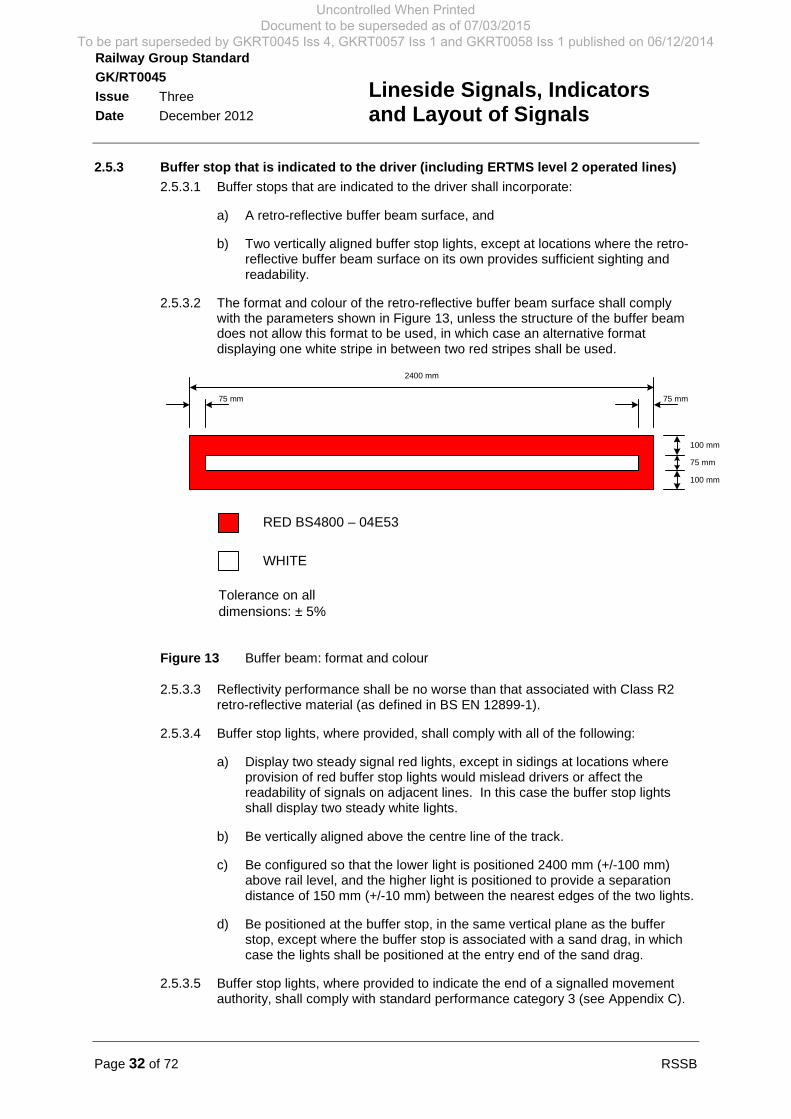
2.5.3.2 The format and colour of the retro-reflective buffer beam surface shall complywith the parameters shown in Figure 13, unless the structure of the buffer beamdoes not allow this format to be used, in which case an alternative formatdisplaying one white stripe in between two red stripes shall be used.
RED BS4800 – 04E53
WHITE
100 mm
75 mm
75 mm75 mm
2400 mm
100 mm
Tolerance on alldimensions: ± 5%
Figure 13 Buffer beam: format and colour
2.5.3.3 Reflectivity performance shall be no worse than that associated with Class R2retro-reflective material (as defined in BS EN 12899-1).
2.5.3.4 Buffer stop lights, where provided, shall comply with all of the following:
a) Display two steady signal red lights, except in sidings at locations whereprovision of red buffer stop lights would mislead drivers or affect thereadability of signals on adjacent lines. In this case the buffer stop lightsshall display two steady white lights.
b) Be vertically aligned above the centre line of the track.
c) Be configured so that the lower light is positioned 2400 mm (+/-100 mm)above rail level, and the higher light is positioned to provide a separationdistance of 150 mm (+/-10 mm) between the nearest edges of the two lights.
d) Be positioned at the buffer stop, in the same vertical plane as the bufferstop, except where the buffer stop is associated with a sand drag, in whichcase the lights shall be positioned at the entry end of the sand drag.
2.5.3.5 Buffer stop lights, where provided to indicate the end of a signalled movementauthority, shall comply with standard performance category 3 (see Appendix C).
Uncontrolled When Printed Document to be superseded as of 07/03/2015
To be part superseded by GKRT0045 Iss 4, GKRT0057 Iss 1 and GKRT0058 Iss 1 published on 06/12/2014

RSSB Page 33 of 72
Railway Group Standard
GK/RT0045
Issue Three
Date December 2012
Lineside Signals, Indicatorsand Layout of Signals
Part 3 Layout of Signals: Requirements for Stop Signals
3.1 Provision of stop signals and signalling indicators3.1.1 Position of stop signals
3.1.1.1 The signalling layout shall provide for all normal train movements.
3.1.1.2 Except for lines where movement authority information is conveyed using linesideoperational signs (see GK/RT0055), the signalling layout shall provide stopsignals at the following locations:
a) At the entrance and exit of every block section.
b) At the entrance to every signal section, including signal sections associatedwith station limits.
c) At the end or exit of every signal section, including signal sectionsassociated with station limits.
d) Where signalling facilities are provided for trains to reverse direction, at thepoint of reversal.
e) On the approach to a ground frame (see GK/RT0077).
f) On the approach to moveable infrastructure, except where a points indicatoris provided instead of a signal (see 3.1.5).
g) On the approach to level crossings (see GK/RT0192).
h) On the approach to areas protected by a signalling lockout system that isprovided for use by railway undertaking personnel, and at the exit from suchan area that is used by personnel working on the outside of trains (seeGK/RT0212).
i) Where there is a requirement to stop trains to protect against other identifiedhazards (for example, airport runways).
3.1.1.3 The requirements for positioning stop signals on electrified lines are set out inAppendix D.
3.1.1.4 Stop signals controlling movements through diverging junctions shall bepositioned not more than 800 m from the first set of facing points, except whereeither:
a) The facing points are operated from a ground frame.
b) The stop signal is positioned parallel with other stop signals, one of which ispositioned within 800 m of a set of facing points and there are other factorsthat prevent the positioning of stop signals closer to the junction.
c) The facing points are always set in the same position for facing moves fromthe stop signal.
d) The facing points are secured out of use (see GC/RT5021).
e) A distance temporarily greater than 800 m is associated with plannedengineering stage-works, and details of the excess distance are published inaccordance with GO/RT3215.
Uncontrolled When Printed Document to be superseded as of 07/03/2015
To be part superseded by GKRT0045 Iss 4, GKRT0057 Iss 1 and GKRT0058 Iss 1 published on 06/12/2014

Page 34 of 72 RSSB
Railway Group Standard
GK/RT0045
Issue Three
Date December 2012
Lineside Signals, Indicatorsand Layout of Signals
3.1.2 Stop signal types, displayed signal aspects and movement authorities
3.1.2.1 Stop signals on running lines shall be main stop signals, except where the criteriafor position light signals, semaphore shunting signals and points indicators allowthese to be provided as an alternative.
3.1.2.2 Main stop signals shall only be provided using the following equipment types:
a) Colour light signal (see 2.2.1).
b) Semaphore main stop signal (see 2.2.6).
c) Stop board (see 2.5.1).
d) Buffer stop that is indicated to the driver (see 2.5.3).
3.1.2.3 The requirements for provision of position light subsidiary signals and semaphoresubsidiary signals are set out in GK/RT0044.
3.1.2.4 Independent position light signals and semaphore shunting signals shall only beprovided to display shunting movement authorities in either one of the followingcircumstances:
a) From running lines into sidings.
b) Wholly within sidings.
c) From sidings onto running lines, except at locations where a colour lightsignal or semaphore stop signal is necessary to mitigate SPAD risk orcollision risk.
d) Along running lines, except at locations where a main stop signal isnecessary to mitigate SPAD risk or collision risk.
3.1.2.5 Before providing a position light signal or semaphore shunting signal to displayshunting movement authorities onto or along running lines, the infrastructuremanager and relevant railway undertaking(s) shall jointly assess the SPAD riskand collision risk associated with the planned train movements. Factors to beconsidered shall include (as appropriate):
a) Visibility and sighting of the stop signal that defines the end of each shuntingmovement authority on the running line.
b) The distance to the stop signal that defines the end of each shuntingmovement authority on the running line.
c) The number and frequency of shunting movements from the signal thatinvolves train movements onto running lines.
d) The proportion of shunting movements from the signal that involve trainmovements onto the running line.
e) The number and proportion of shunting movements from the signal into anoccupied section on a passenger line.
3.1.2.6 Where an independent position light signal is provided within a main signal routein a facing direction, the following apply:
a) The position light signal OFF aspect comprising two lunar white lights (see2.2.5) shall be displayed when the route is set from the main stop signal, and
Uncontrolled When Printed Document to be superseded as of 07/03/2015
To be part superseded by GKRT0045 Iss 4, GKRT0057 Iss 1 and GKRT0058 Iss 1 published on 06/12/2014
RSSB Page 35 of 72
Railway Group Standard
GK/RT0045
Issue Three
Date December 2012
Lineside Signals, Indicatorsand Layout of Signals
b) The position light signal ON aspect shall only be displayed to a driver usinga movement authority from the main stop signal if the signaller intentionallyreplaces the signal to danger in an emergency.
3.1.2.7 Where a semaphore shunting signal is provided within a main signal route in afacing direction:
a) The OFF aspect shall be displayed when the route is set from the main stopsignal, and
b) The ON aspect shall only be displayed to a driver using a movementauthority from the main stop signal if the signaller intentionally replaces thesignal to danger in an emergency.
3.1.2.8 Stepping up or down to a calling-on class route is prohibited.
3.1.2.9 Stepping up or down to a shunt class route is prohibited.
3.1.2.10 Stepping up or down to a PoSA class route is prohibited.
3.1.3 Designation of colour light stop signals as ‘passable’ and ‘non-passable’
3.1.3.1 All colour light signals configured as stop signals shall be designated either‘passable’ or ‘non-passable’.
3.1.3.2 A colour light stop signal shall be designated ‘non-passable’ if it displays amovement authority into a signal section(s) that incorporates any of the following:
a) Ground frame.
b) Crossover, facing or trailing points.
c) Moveable infrastructure (for example, a swing bridge) Moveableinfrastructure (for example, a swing bridge).
d) Manually controlled level crossing.
e) Automatic level crossing remotely monitored by the signaller.
f) A directly opposing route or overlap that conflicts with the route or overlap.
g) A signal section that is not worked in accordance with track circuit blockregulations, with the exception of signals designated as intermediate blockhome signals (see 3.1.4).
h) Any other hazard protected by the stop signal that, if passed at danger,could result in a collision or derailment.
3.1.3.3 A colour light stop signal shall be designated ‘non-passable’ if a stop aspect isdisplayed as part of a protection system, in accordance with the GE/RT8000 RuleBook, for example:
a) On the approach to an electrification supply section that can be isolated, and
b) On the approach to, and at the exit from, a staff protection system (forexample, a signalling lockout system).
3.1.3.4 A colour light stop signal shall only be designated ‘passable’ when all of thefollowing apply:
a) If none of the features set out in 3.1.3.2 and 3.1.3.3 apply.
Uncontrolled When Printed Document to be superseded as of 07/03/2015
To be part superseded by GKRT0045 Iss 4, GKRT0057 Iss 1 and GKRT0058 Iss 1 published on 06/12/2014
Page 36 of 72 RSSB
Railway Group Standard
GK/RT0045
Issue Three
Date December 2012
Lineside Signals, Indicatorsand Layout of Signals
b) If the operational features within the signal section are compatible with theoperational rules for passing signals at danger on the driver’s own authority,as set out in the GE/RT8000 Rule Book.
c) After the SPAD risk at the signal at the end of the section has beenassessed, if the overlap at the end of a signal section incorporates moveableinfrastructure or a level crossing.
3.1.4 Designation of a stop signal as an ‘intermediate block home’ signal
3.1.4.1 A colour light stop signal or semaphore main stop signal shall only be designatedan ‘intermediate block home’ signal if:
a) The signal is located at the end of an additional block section that iscontrolled by one signal box and operated in accordance with the absoluteblock regulations, and
b) The criteria for designating the signal as a ‘passable’ signal apply (see3.1.3.4).
3.1.5 Provision of point indicators
3.1.5.1 A points indicator (see 2.4.1) shall be provided:
a) On the approach to facing points unless a stop signal is used to displaymovement authorities through those points, and
b) On the approach to trailing points, unless either:
i) A stop signal is used to display movement authorities through thosepoints, or
ii) A train operated point mechanism is fitted to the trailing points.
3.1.6 Provision of loading / unloading indicators
3.1.6.1 Loading / unloading indicators (see 2.4.3) shall be provided at locations wherethe infrastructure manager co-operates with railway undertaking shuntingoperations by displaying train movement indications in lieu of hand-signallingoperations.
3.1.6.2 Where loading / unloading indicators are grouped as a set along a line, all of theindicators in the set shall display the same indication at the same time.
3.1.6.3 A stop signal shall protect the running lines beyond the sidings in accordancewith 3.1.1.
3.1.6.4 No indication shall be displayed for movements into a signalled area when thesignal applicable to the movement is displaying a stop aspect.
3.1.6.5 The number, position and alignment of loading / unloading indicators shallprovide for unobstructed sighting and readability of at least one indicator at alltimes under conditions of clear visibility.
Uncontrolled When Printed Document to be superseded as of 07/03/2015
To be part superseded by GKRT0045 Iss 4, GKRT0057 Iss 1 and GKRT0058 Iss 1 published on 06/12/2014
RSSB Page 37 of 72
Railway Group Standard
GK/RT0045
Issue Three
Date December 2012
Lineside Signals, Indicatorsand Layout of Signals
Part 4 Layout of Signals: Aspect Sequences
4.1 Requirements for cautionary aspect sequences4.1.1 Standard 3-aspect sequence
4.1.1.1 In 3-aspect colour light signalling areas, a first caution consisting of a singleyellow aspect shall be displayed at the required signalling braking distance fromthe red aspect (see GK/RT0075).
4.1.1.2 The standard 3-aspect sequence shall be:
Green → Single yellow → Red
4.1.2 Standard 4-aspect sequence
4.1.2.1 In 4-aspect colour light signalling areas:
a) A first caution consisting of a double yellow aspect shall be displayed at therequired signalling braking distance from the red aspect (see GK/RT0075),and
b) The red aspect shall also be preceded by a single yellow aspect displayed atthe required signalling braking distance (see GK/RT0075).
4.1.2.2 The standard 4-aspect sequence shall be:
Green → Double yellow → Single yellow → Red
4.1.3 Non-standard 4-aspect sequences
4.1.3.1 By exception, the signalling system shall only display the following non-standard4-aspect sequences, either:
a) A sequence incorporating two successive double yellow aspects (see4.1.3.2), or
b) A sequence incorporating two successive single yellow aspects (see4.1.3.3).
4.1.3.2 A sequence incorporating two successive double yellow aspects shall only bedisplayed where it is necessary to achieve the required signalling brakingdistance between the first double yellow aspect and the red aspect. In this casethe non-standard 4-aspect sequence shall be:
Green → Double yellow → Double yellow → Single yellow → Red
4.1.3.3 A sequence incorporating two successive single yellow aspects shall only bedisplayed where it is necessary to provide the required signalling braking distancebetween the single yellow aspect and the red aspect in a 4-aspect sequence. Inthis case the non-standard 4-aspect sequence shall be:
Green → Double yellow → Single yellow → Single yellow → Red
Uncontrolled When Printed Document to be superseded as of 07/03/2015
To be part superseded by GKRT0045 Iss 4, GKRT0057 Iss 1 and GKRT0058 Iss 1 published on 06/12/2014

Page 38 of 72 RSSB
Railway Group Standard
GK/RT0045
Issue Three
Date December 2012
Lineside Signals, Indicatorsand Layout of Signals
4.1.3.4 Where a non-standard 4-aspect sequence is provided, the train protection system(see GE/RT8030) shall be configured to mitigate the additional SPAD risk thatarises:
a) At the signal that displays the single yellow aspect as part of the non-standard 4-aspect sequence incorporating two double yellow aspects, and
b) At the signal that displays the second single yellow aspect as part of thenon-standard 4-aspect sequence incorporating two single yellow aspects.
4.1.3.5 Signal heads that do not display a double yellow aspect as part of a non-standard4-aspect sequence shall retain the same signal head format as the 4-aspectsignals in the sequence.
4.1.3.6 Where, in a non-standard 4-aspect sequence, the stop signal is a junction signalfor which the diverging route is not approach controlled from red, sufficientdistance shall be provided to the signal beyond the junction on the divergingroute so that a train traversing the junction at the permissible speed can stop atthat signal.
4.1.4 Cautionary aspect sequence transition methods: 3-aspect to 4-aspect signalling
4.1.4.1 The transition from a 3-aspect sequence to a 4-aspect sequence (including wherean isolated 4-aspect signal is displayed within an otherwise 3-aspect sequence),shall be provided using either one of the following:
a) Transition method 1: Using a signal that displays a first caution for both ofthe next two stop signals (see 4.1.4.2).
b) Transition method 2: Using an additional 4-aspect distant signal (see4.1.4.5).
c) Transition method 3: By configuring the first 4-aspect signal so that it isapproach controlled from red when the next signal is displaying the redaspect (see 4.1.4.6).
4.1.4.2 Where transition method 1 is used (see Figure 14), the first 4-aspect signal(signal 5) shall display:
a) A 3-aspect sequence first caution (see 4.1.1.1) when the next signal(signal 7) is displaying the red aspect, and
b) A 4-aspect first caution (see 4.1.2.1) when the next signal (signal 7) isdisplaying the single yellow aspect and the next but one signal (signal 9) isdisplaying the red aspect.
4.1.4.3 Where transition method 1 is used, the train protection system shall be configuredto mitigate the additional SPAD risk at the signal that displays the red aspect atthe end of the last 3-aspect sequence (signal 7).
4.1.4.4 The particular signalling braking requirements for 3-aspect to 4-aspect transitionsat converging junctions (where attainable speed is a factor) are set out inGK/RT0075.
Uncontrolled When Printed Document to be superseded as of 07/03/2015
To be part superseded by GKRT0045 Iss 4, GKRT0057 Iss 1 and GKRT0058 Iss 1 published on 06/12/2014

RSSB Page 39 of 72
Railway Group Standard
GK/RT0045
Issue Three
Date December 2012
Lineside Signals, Indicatorsand Layout of Signals
3asp 3asp 4asp 4asp 4asp 4asp 4asp
1 3 5 7* 9 11 13
* Train protection system (eg TPWS) required at this signal (No. 7)
G
G
G
G
G
G
G
Y
Y
Y
Y
Y
Y
R
R
R
R
R
YY
YY
YY
YY
YY
Figure 14 Example of a 3-aspect to 4-aspect transition using transition method 1
4.1.4.5 Where transition method 2 is used (see Figure 15), an additional 4-aspect distantsignal (signal 7) shall be provided within the transition sequence at the requiredsignalling braking distance (see GK/RT0075) and the signalling system shall beconfigured so that all of the following apply:
a) The first 4-aspect signal (signal 5) does not display a single yellow aspect.
b) The first 4-aspect signal (signal 5) displays the 4-aspect first caution (see4.1.2.1) when the next signal (signal 7) is displaying the single yellow aspectand the next but one signal (signal 9) is displaying the red aspect.
c) The additional 4-aspect distant signal (signal 7) displays the appropriatecautionary aspects relevant to the standard 4-aspect sequence. This signaldoes not display a red aspect.
3asp 3asp 4asp
Additionaldistant signal
4asp 4asp 4asp
1 3 5
7
9 11 13
G
G
G
G
G
G
Y
Y
Y
Y
Y
R
R
R
R
YY
YY
YY
YY
YY
G
4asp
Figure 15 Example of a 3-aspect to 4-aspect transition using transition method 2
Uncontrolled When Printed Document to be superseded as of 07/03/2015
To be part superseded by GKRT0045 Iss 4, GKRT0057 Iss 1 and GKRT0058 Iss 1 published on 06/12/2014
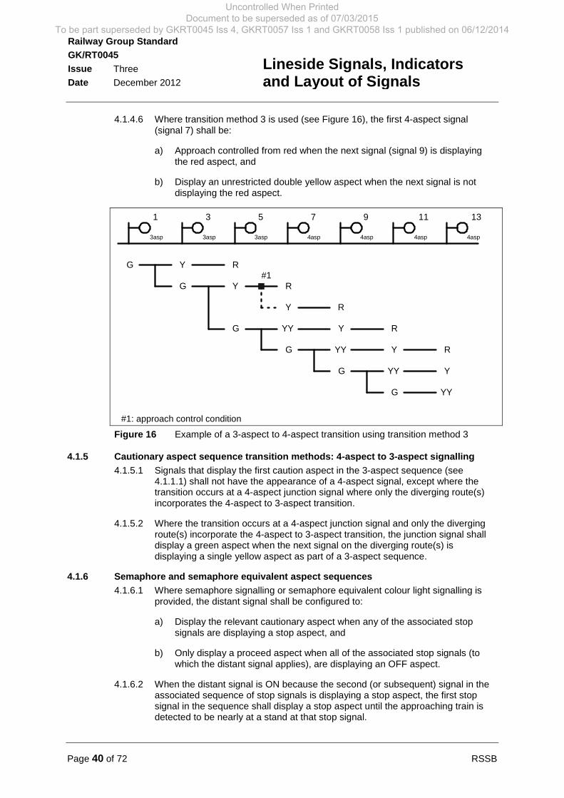
Page 40 of 72 RSSB
Railway Group Standard
GK/RT0045
Issue Three
Date December 2012
Lineside Signals, Indicatorsand Layout of Signals
4.1.4.6 Where transition method 3 is used (see Figure 16), the first 4-aspect signal(signal 7) shall be:
a) Approach controlled from red when the next signal (signal 9) is displayingthe red aspect, and
b) Display an unrestricted double yellow aspect when the next signal is notdisplaying the red aspect.
3asp 3asp 3asp 4asp 4asp 4asp 4asp
1 3 5 7 9 11 13
G
G
G
G
G
Y
Y
Y
Y
Y
R
R
R
R
YY
YY
YY
YY
G
Y R
#1
#1: approach control condition
Figure 16 Example of a 3-aspect to 4-aspect transition using transition method 3
4.1.5 Cautionary aspect sequence transition methods: 4-aspect to 3-aspect signalling
4.1.5.1 Signals that display the first caution aspect in the 3-aspect sequence (see4.1.1.1) shall not have the appearance of a 4-aspect signal, except where thetransition occurs at a 4-aspect junction signal where only the diverging route(s)incorporates the 4-aspect to 3-aspect transition.
4.1.5.2 Where the transition occurs at a 4-aspect junction signal and only the divergingroute(s) incorporate the 4-aspect to 3-aspect transition, the junction signal shalldisplay a green aspect when the next signal on the diverging route(s) isdisplaying a single yellow aspect as part of a 3-aspect sequence.
4.1.6 Semaphore and semaphore equivalent aspect sequences
4.1.6.1 Where semaphore signalling or semaphore equivalent colour light signalling isprovided, the distant signal shall be configured to:
a) Display the relevant cautionary aspect when any of the associated stopsignals are displaying a stop aspect, and
b) Only display a proceed aspect when all of the associated stop signals (towhich the distant signal applies), are displaying an OFF aspect.
4.1.6.2 When the distant signal is ON because the second (or subsequent) signal in theassociated sequence of stop signals is displaying a stop aspect, the first stopsignal in the sequence shall display a stop aspect until the approaching train isdetected to be nearly at a stand at that stop signal.
Uncontrolled When Printed Document to be superseded as of 07/03/2015
To be part superseded by GKRT0045 Iss 4, GKRT0057 Iss 1 and GKRT0058 Iss 1 published on 06/12/2014
RSSB Page 41 of 72
Railway Group Standard
GK/RT0045
Issue Three
Date December 2012
Lineside Signals, Indicatorsand Layout of Signals
4.1.6.3 Where the next signal beyond a semaphore distant signal is a semaphore stopsignal to which the distant signal does not apply, a repeat semaphore distantsignal arm shall be provided in association with that signal.
4.1.6.4 Where a semaphore distant signal arm is provided at a signal that is also asemaphore stop signal, the distant signal arm shall:
a) Be positioned below the semaphore stop signal arm and on the same signalpost, and
b) Only display the proceed aspect when the semaphore stop signal arm isalso displaying a proceed aspect.
4.1.7 Aspects displayed by colour light signals that do not have main routes reading up tothem
4.1.7.1 In 4-aspect colour light signalling areas, a stop signal that does not have a mainroute reading up to it shall display the following OFF aspects:
a) When the next signal ahead is displaying the red aspect, it shall display thesingle yellow aspect.
b) When the next signal ahead is displaying the single yellow aspect, it shalldisplay either:
i) The double yellow aspect, or
ii) The green aspect, only if the signalling braking distance between thenext two stop signals is compatible with the attainable speed of thetrain (see GK/RT0075).
4.1.8 Approach lit colour light signals
4.1.8.1 Approach lit colour light signals shall only extinguish the signal aspect when:
a) The signal does not define the start or end of a movement authority thatcould be approached by a signalled train movement, and
b) The signal does not contribute to the sighting of signals within the signallinglayout.
4.1.9 Cautionary aspect sequence approaching a points indicator
4.1.9.1 Except where all trains start from rest within sight of the points indicator, a cautionaspect shall be displayed at the required signalling braking distance from thepoints indicator (see GK/RT0075), using either one of the following signals:
a) A distant board (see 2.5.2), or
b) A semaphore distant signal arm fixed in the ON position (see 2.2.6).
4.1.10 Cautionary aspect sequence approaching a stop board
4.1.10.1 Except where a stop board is only approached by a shunting movement or whereall trains start from rest within sight of the stop board, a caution aspect shall bedisplayed at the required signalling braking distance from the stop board (seeGK/RT0075), using any one of the following:
a) A distant board (see 2.5.2).
b) A semaphore distant signal displaying the caution aspect (see 2.2.6).
Uncontrolled When Printed Document to be superseded as of 07/03/2015
To be part superseded by GKRT0045 Iss 4, GKRT0057 Iss 1 and GKRT0058 Iss 1 published on 06/12/2014
Page 42 of 72 RSSB
Railway Group Standard
GK/RT0045
Issue Three
Date December 2012
Lineside Signals, Indicatorsand Layout of Signals
c) A colour light signal displaying a single yellow aspect (see 2.2.1).
d) A level crossing warning sign provided in accordance with GK/RT0192.
4.1.11 Cautionary aspect sequence approaching a buffer stop at the end of a signalledroute
4.1.11.1 Except on lines with ETCS cab signalling, a cautionary aspect sequence shall bedisplayed at the required signalling braking distance (see GK/RT0075) on theapproach to the buffer stop at the end of main signal routes. The cautionaryaspect sequence shall be displayed using one of the following:
a) An aspect sequence appropriate to the prevailing type of signalling, wherethe stop aspect is displayed by the buffer stop.
b) A distant board (see 2.5.2).
c) A semaphore distant signal arm fixed in the ON position (see 2.2.6).
d) An isolated colour light distant signal displaying a signal yellow aspect (see2.2.1).
4.1.12 Cautionary aspect sequences at transitions between signalling systems
4.1.12.1 Within the transition zone between different types of lineside signalling systems,the sequence of displayed signal aspects and indications shall be compatiblewith:
a) The sequence of aspects leading up to the stop signal at the end of thesignalled movement authority that is displayed by the other signallingsystem, and
b) The permissible speed associated with the movement authority.
4.1.12.2 Additional requirements for transitions between signalling systems are set out inGK/RT0036.
4.2 Requirements for banner repeating signal aspects4.2.1 Banner repeating signal aspect sequences
4.2.1.1 The requirements for provision of banner repeating signals are set out inGE/RT8037.
4.2.1.2 2-state banner repeating signals (see 2.2.4) shall display:
a) The white OFF aspect when the signal that is being repeated is displayingan OFF aspect for the route(s) to which it refers, and
b) The ON aspect at all other times.
4.2.1.3 3-state banner repeating signals shall only be provided to repeat colour lightsignals.
4.2.1.4 3-state banner repeating signals (see 2.2.4) shall display:
a) The green OFF aspect when the signal that is being repeated is displayingthe green aspect for the route(s) to which it refers.
Uncontrolled When Printed Document to be superseded as of 07/03/2015
To be part superseded by GKRT0045 Iss 4, GKRT0057 Iss 1 and GKRT0058 Iss 1 published on 06/12/2014
RSSB Page 43 of 72
Railway Group Standard
GK/RT0045
Issue Three
Date December 2012
Lineside Signals, Indicatorsand Layout of Signals
b) The white OFF aspect when the signal that is being repeated is displaying acautionary aspect for the route(s) to which it refers.
c) The ON aspect at all other times.
4.2.2 Splitting banner repeating signal aspect sequences
4.2.2.1 Splitting banner repeating signals (see 2.2.4) shall only be provided where:
a) A banner repeating signal is required on the approach to a junction signal(see 5.2), and
b) It is necessary to distinguish between an OFF banner aspect for differentroutes at the diverging junction.
4.2.2.2 Where there is no obvious straight ahead route at the junction and an equalheight splitting banner repeating signal is provided, the relative horizontalpositions of the two heads shall correspond with the direction of the divergence(left hand or right hand) at the junction.
4.2.2.3 Where a splitting banner repeating signal incorporating heads mounted atdifferent heights is provided:
a) The higher head shall apply to the straight ahead route (which is the fastestroute) and shall only clear for the straight ahead route, and
b) The lower head shall apply to the diverging route(s) and shall only clear forthat divergence.
4.2.2.4 The ON aspect shall be displayed by both signal heads at all times, except whenthe related junction signal is cleared, in which case the appropriate white OFF orgreen OFF aspect shall be displayed only in the signal head that correspondswith the route that is set at the junction, and the ON aspect shall be displayed inthe other signal head.
4.2.2.5 Splitting banner repeating signals shall only be configured to display an OFFaspect for more than one diverging route if the associated diverging routes:
a) Have permissible speeds that do not differ by more than 10 mph, and
b) Do not differ in any characteristic that could affect operational safety.
Uncontrolled When Printed Document to be superseded as of 07/03/2015
To be part superseded by GKRT0045 Iss 4, GKRT0057 Iss 1 and GKRT0058 Iss 1 published on 06/12/2014
Page 44 of 72 RSSB
Railway Group Standard
GK/RT0045
Issue Three
Date December 2012
Lineside Signals, Indicatorsand Layout of Signals
Part 5 Layout of Signals: Junction Signalling
5.1 Requirements for route indications5.1.1 Provision of route indicators
5.1.1.1 Junction signals shall display each required route indication as part of the signalaspect, using one of the following arrangements:
a) A position light junction indicator (see 2.3.1).
b) An alphanumeric junction indicator (see 2.3.2).
c) A position light junction indicator in combination with an alphanumeric routeindicator.
5.1.1.2 Standard alphanumeric route indicators shall be used to display alphanumericroute indications in conjunction with all standard performance categories 1 and 4signal aspects, except where:
a) Environmental and physical positioning constraints associated with a signalmean that a standard alphanumeric route indicator cannot be used, and
b) Provision of a miniature alphanumeric route indicator is compatible with thesignal sighting and readability requirements, subject to assessment of therisk of drivers misreading the displayed movement authority.
5.1.1.3 Miniature alphanumeric route indicators shall be used to display alphanumericroute indications in conjunction with all standard performance category 3 signalaspects, unless either:
a) By exception only, where an existing signalling layout that displays standardalphanumeric route indications in conjunction with position light signalaspects is being modified, and subject to signal sighting requirements andan assessment of the risk of drivers misreading the displayed movementauthority, or
a) A proceed on sight (PoSA) aspect is displayed in lieu of a colour light signalaspect in combination with a standard alphanumeric route indicator.
5.1.2 Display of route indications
5.1.2.1 Junction signals shall display a route indication for all diverging routes.
5.1.2.2 Junction signals shall only display one position light junction indication at a time.
5.1.2.3 Where a position light junction indicator is provided, a route indication shall bedisplayed for all routes at a diverging junction where either:
a) There is no geographically obvious straight ahead route, or
b) The straightest alignment through the junction is an unsignalled route.
5.1.2.4 Where an alphanumeric route indicator is provided with a colour light signal orsemaphore main stop signal, a route indication shall be displayed for the straightahead route at a diverging junction where either:
a) There is no geographically obvious straight ahead route.
Uncontrolled When Printed Document to be superseded as of 07/03/2015
To be part superseded by GKRT0045 Iss 4, GKRT0057 Iss 1 and GKRT0058 Iss 1 published on 06/12/2014

RSSB Page 45 of 72
Railway Group Standard
GK/RT0045
Issue Three
Date December 2012
Lineside Signals, Indicatorsand Layout of Signals
b) The permitted speed for the straight ahead route is less than 10 mph abovethat for any diverging route.
c) One or more of the routes leads to a station platform.
5.1.2.5 An alphanumeric route indication shall be displayed in conjunction with allposition light subsidiary signal OFF aspects unless there is only one subsidiaryroute to which the signal applies and that route does not end at a limit of shuntsignal.
5.1.2.6 An alphanumeric route indication shall be displayed in conjunction with allindependent position light signal OFF aspects except that no route indicator isrequired if:
a) There is only one route from the signal and that route does not end at a limitof shunt signal.
b) There is more than one route, where all of the following apply:
i) None of the routes end at a limit of shunt signal.
ii) None of the routes end at a signal where the consequence of a SPADcould be a serious hazard.
iii) There is no significant difference in the distances to the next signals.
iv) The infrastructure characteristics for each route are similar in nature.
v) No safety hazard will arise if the train proceeds along an incorrect route.
5.1.2.7 Where alternative routes are available from a junction signal to the samedestination, a common route indication shall be displayed by that signal for eachof the routes only if both of the following apply:
a) The difference in permissible speed for each alternative route is not morethan 10 mph, and
b) There is no difference between the routes in terms of infrastructurecharacteristics.
5.1.2.8 Where more than one signal is configured to display an alphanumeric routeindication to a particular destination (for example, a station platform), the samealphanumeric indication shall be displayed by each of the signals.
5.1.2.9 The same alphanumeric route indication shall not be displayed by separatesignals for movements towards different destinations at any one locality.
5.1.3 Configuration of signal OFF aspects and route indications
5.1.3.1 Where a position light junction indicator is provided, the signalling system shall beconfigured so that:
a) The position light junction indicator only displays a route indication when thejunction signal aspect controls permit an OFF aspect to be displayed, and
b) This junction signal OFF aspect is only displayed if the appropriate positionlight junction indicator is displaying a minimum of three white lights.
5.1.3.2 Where an alpha-numeric route indicator is provided, the signalling system shallbe configured so that:
Uncontrolled When Printed Document to be superseded as of 07/03/2015
To be part superseded by GKRT0045 Iss 4, GKRT0057 Iss 1 and GKRT0058 Iss 1 published on 06/12/2014
Page 46 of 72 RSSB
Railway Group Standard
GK/RT0045
Issue Three
Date December 2012
Lineside Signals, Indicatorsand Layout of Signals
a) The alphanumeric route indicator only displays a route indication when thesignal aspect controls permit an OFF aspect to be displayed, and
b) This OFF signal aspect is only displayed when the associated alphanumericroute indication is correctly displayed, except that no proving is required forroute indications where either:
i) The signal displays a proceed on sight (PoSA) aspect.
ii) There is only one route from a signal and the signal does not display amovement authority up to a limit of shunt signal.
iii) There is more than one route and all of the following apply. (Thisexemption does not apply to colour light signals or semaphore mainstop signals):
None of the routes end at a limit of shunt signal.
None of the routes end at a signal where the consequence of aSPAD could be a serious hazard.
There is no significant difference in the distances to the nextsignal.
The infrastructure characteristics are similar in nature.
No safety hazard arises if the train proceeds along the incorrectroute.
5.1.3.3 The position of junction signals shall, if practicable, be such that the driver of anapproaching train can read the route indicator at the same time as the associatedOFF aspects.
5.1.3.4 If the position of the junction signal is such that the driver of an approaching traincannot read the route indicator at the same time as the OFF aspects, then thejunction signal shall be approach controlled from red (see 5.2.4), except:
a) Where flashing aspect sequences are provided (see 5.2.3) and theapproaching train is detected to be in a position that is compatible with therequired reading time of the junction distant signal that displays the flashingsingle yellow aspect, and
b) Where splitting distant signals are provided (see 5.2.6) and the approachingtrain is detected to be in a position that is compatible with the requiredreading time of the splitting distant signal immediately preceding the junctionsignal.
5.1.4 Provision of preliminary route indicators
5.1.4.1 A preliminary route indicator (see 2.3.3) shall only be provided:
a) To enhance the standard junction signalling arrangements set out in 5.2, and
b) Where the junction signal is fitted with a position light junction indicator.
Uncontrolled When Printed Document to be superseded as of 07/03/2015
To be part superseded by GKRT0045 Iss 4, GKRT0057 Iss 1 and GKRT0058 Iss 1 published on 06/12/2014
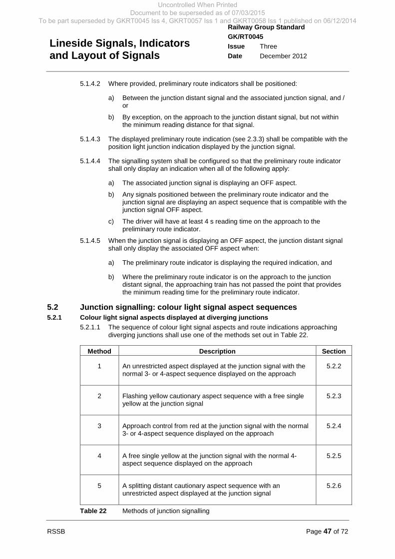
RSSB Page 47 of 72
Railway Group Standard
GK/RT0045
Issue Three
Date December 2012
Lineside Signals, Indicatorsand Layout of Signals
5.1.4.2 Where provided, preliminary route indicators shall be positioned:
a) Between the junction distant signal and the associated junction signal, and /or
b) By exception, on the approach to the junction distant signal, but not withinthe minimum reading distance for that signal.
5.1.4.3 The displayed preliminary route indication (see 2.3.3) shall be compatible with theposition light junction indication displayed by the junction signal.
5.1.4.4 The signalling system shall be configured so that the preliminary route indicatorshall only display an indication when all of the following apply:
a) The associated junction signal is displaying an OFF aspect.
b) Any signals positioned between the preliminary route indicator and thejunction signal are displaying an aspect sequence that is compatible with thejunction signal OFF aspect.
c) The driver will have at least 4 s reading time on the approach to thepreliminary route indicator.
5.1.4.5 When the junction signal is displaying an OFF aspect, the junction distant signalshall only display the associated OFF aspect when:
a) The preliminary route indicator is displaying the required indication, and
b) Where the preliminary route indicator is on the approach to the junctiondistant signal, the approaching train has not passed the point that providesthe minimum reading time for the preliminary route indicator.
5.2 Junction signalling: colour light signal aspect sequences5.2.1 Colour light signal aspects displayed at diverging junctions
5.2.1.1 The sequence of colour light signal aspects and route indications approachingdiverging junctions shall use one of the methods set out in Table 22.
Method Description Section
1 An unrestricted aspect displayed at the junction signal with thenormal 3- or 4-aspect sequence displayed on the approach
5.2.2
2 Flashing yellow cautionary aspect sequence with a free singleyellow at the junction signal
5.2.3
3 Approach control from red at the junction signal with the normal3- or 4-aspect sequence displayed on the approach
5.2.4
4 A free single yellow at the junction signal with the normal 4-aspect sequence displayed on the approach
5.2.5
5 A splitting distant cautionary aspect sequence with anunrestricted aspect displayed at the junction signal
5.2.6
Table 22 Methods of junction signalling
Uncontrolled When Printed Document to be superseded as of 07/03/2015
To be part superseded by GKRT0045 Iss 4, GKRT0057 Iss 1 and GKRT0058 Iss 1 published on 06/12/2014
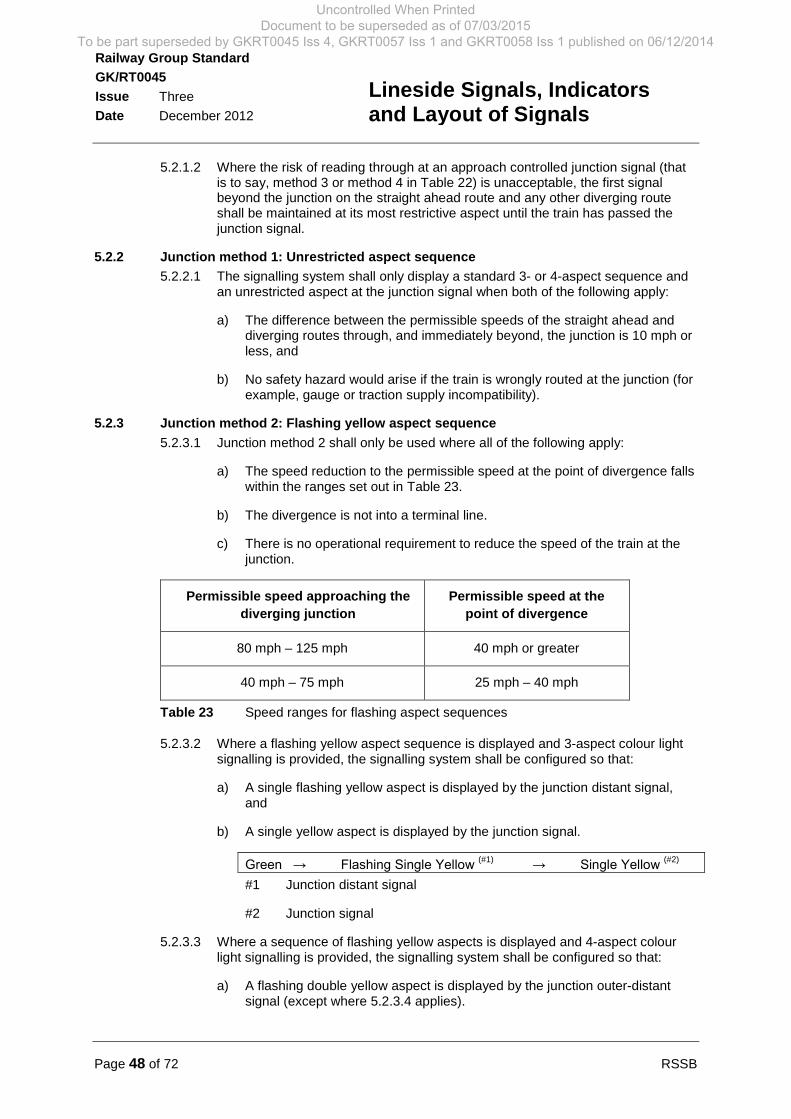
Page 48 of 72 RSSB
Railway Group Standard
GK/RT0045
Issue Three
Date December 2012
Lineside Signals, Indicatorsand Layout of Signals
5.2.1.2 Where the risk of reading through at an approach controlled junction signal (thatis to say, method 3 or method 4 in Table 22) is unacceptable, the first signalbeyond the junction on the straight ahead route and any other diverging routeshall be maintained at its most restrictive aspect until the train has passed thejunction signal.
5.2.2 Junction method 1: Unrestricted aspect sequence
5.2.2.1 The signalling system shall only display a standard 3- or 4-aspect sequence andan unrestricted aspect at the junction signal when both of the following apply:
a) The difference between the permissible speeds of the straight ahead anddiverging routes through, and immediately beyond, the junction is 10 mph orless, and
b) No safety hazard would arise if the train is wrongly routed at the junction (forexample, gauge or traction supply incompatibility).
5.2.3 Junction method 2: Flashing yellow aspect sequence
5.2.3.1 Junction method 2 shall only be used where all of the following apply:
a) The speed reduction to the permissible speed at the point of divergence fallswithin the ranges set out in Table 23.
b) The divergence is not into a terminal line.
c) There is no operational requirement to reduce the speed of the train at thejunction.
Permissible speed approaching the
diverging junction
Permissible speed at the
point of divergence
80 mph – 125 mph 40 mph or greater
40 mph – 75 mph 25 mph – 40 mph
Table 23 Speed ranges for flashing aspect sequences
5.2.3.2 Where a flashing yellow aspect sequence is displayed and 3-aspect colour lightsignalling is provided, the signalling system shall be configured so that:
a) A single flashing yellow aspect is displayed by the junction distant signal,and
b) A single yellow aspect is displayed by the junction signal.
Green → Flashing Single Yellow (#1)
→ Single Yellow (#2)
#1 Junction distant signal
#2 Junction signal
5.2.3.3 Where a sequence of flashing yellow aspects is displayed and 4-aspect colourlight signalling is provided, the signalling system shall be configured so that:
a) A flashing double yellow aspect is displayed by the junction outer-distantsignal (except where 5.2.3.4 applies).
Uncontrolled When Printed Document to be superseded as of 07/03/2015
To be part superseded by GKRT0045 Iss 4, GKRT0057 Iss 1 and GKRT0058 Iss 1 published on 06/12/2014
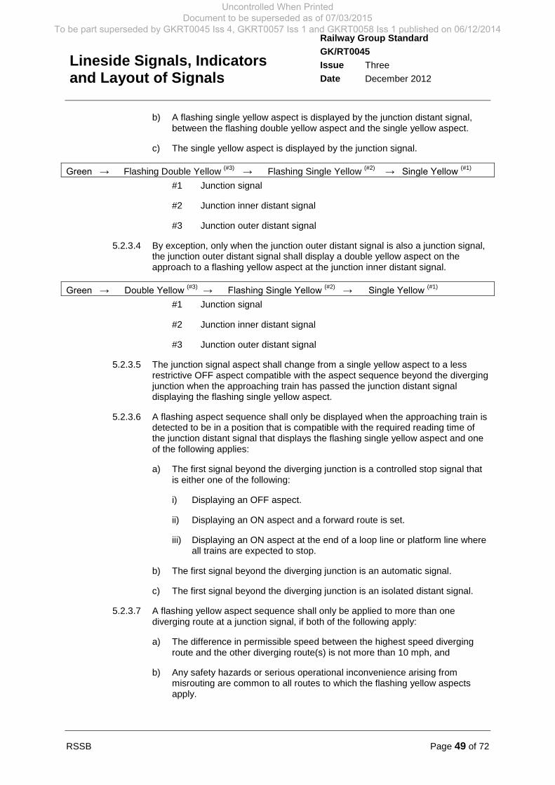
RSSB Page 49 of 72
Railway Group Standard
GK/RT0045
Issue Three
Date December 2012
Lineside Signals, Indicatorsand Layout of Signals
b) A flashing single yellow aspect is displayed by the junction distant signal,between the flashing double yellow aspect and the single yellow aspect.
c) The single yellow aspect is displayed by the junction signal.
Green → Flashing Double Yellow(#3)
→ Flashing Single Yellow(#2)
→ Single Yellow (#1)
#1 Junction signal
#2 Junction inner distant signal
#3 Junction outer distant signal
5.2.3.4 By exception, only when the junction outer distant signal is also a junction signal,the junction outer distant signal shall display a double yellow aspect on theapproach to a flashing yellow aspect at the junction inner distant signal.
Green → Double Yellow (#3)
→ Flashing Single Yellow (#2)
→ Single Yellow (#1)
#1 Junction signal
#2 Junction inner distant signal
#3 Junction outer distant signal
5.2.3.5 The junction signal aspect shall change from a single yellow aspect to a lessrestrictive OFF aspect compatible with the aspect sequence beyond the divergingjunction when the approaching train has passed the junction distant signaldisplaying the flashing single yellow aspect.
5.2.3.6 A flashing aspect sequence shall only be displayed when the approaching train isdetected to be in a position that is compatible with the required reading time ofthe junction distant signal that displays the flashing single yellow aspect and oneof the following applies:
a) The first signal beyond the diverging junction is a controlled stop signal thatis either one of the following:
i) Displaying an OFF aspect.
ii) Displaying an ON aspect and a forward route is set.
iii) Displaying an ON aspect at the end of a loop line or platform line whereall trains are expected to stop.
b) The first signal beyond the diverging junction is an automatic signal.
c) The first signal beyond the diverging junction is an isolated distant signal.
5.2.3.7 A flashing yellow aspect sequence shall only be applied to more than onediverging route at a junction signal, if both of the following apply:
a) The difference in permissible speed between the highest speed divergingroute and the other diverging route(s) is not more than 10 mph, and
b) Any safety hazards or serious operational inconvenience arising frommisrouting are common to all routes to which the flashing yellow aspectsapply.
Uncontrolled When Printed Document to be superseded as of 07/03/2015
To be part superseded by GKRT0045 Iss 4, GKRT0057 Iss 1 and GKRT0058 Iss 1 published on 06/12/2014
Page 50 of 72 RSSB
Railway Group Standard
GK/RT0045
Issue Three
Date December 2012
Lineside Signals, Indicatorsand Layout of Signals
5.2.4 Junction method 3: Approach control from red
5.2.4.1 Where it is not appropriate to use a less restrictive method, the signalling systemshall be configured to display a cautionary aspect sequence leading up toapproach control from red at the junction signal.
5.2.4.2 The junction signal shall display the red aspect until the approaching train isdetected to have:
a) Passed the junction distant signal, and
b) Passed the banner signal (where provided with the junction signal), exceptwhere a splitting banner signal aspect is displayed.
5.2.4.3 When the approach control has been satisfied, the OFF aspect displayed at thejunction signal shall be compatible with the aspect sequence on the divergingroute.
5.2.5 Junction method 4: Approach control from single yellow
5.2.5.1 By exception, the signalling system shall only be configured to display the normal4-aspect sequence leading up to a free single yellow at the junction signal, whereall of the following apply:
a) It is not appropriate to use junction method 1 or junction method 2.
b) All rolling stock that operates over the route has a consistent brakingcharacteristic (see GK/RT0075).
c) The signalling braking distances (see GK/RT0075) is compatible with therequirements for 4-aspect signalling between:
i) The junction distant signal that displays the double yellow aspect andthe junction signal, and
ii) The junction signal and the first signals on all routes beyond thejunction.
d) The braking performance of the rolling stock shall be compatible with:
i) The distance between the junction distant signal that displays thedouble yellow aspect and the point of divergence, and
ii) The required speed reduction to the permissible speed at the point ofdivergence.
e) The highest permissible speed for any route at the junction is 60 mph orless.
f) The difference in speed for the divergence is greater than 10 mph and notmore than 30 mph.
5.2.5.2 When the diverging route is set:
a) The junction signal shall display the single yellow aspect, and
b) The junction distant signal shall display the double yellow aspect.
Uncontrolled When Printed Document to be superseded as of 07/03/2015
To be part superseded by GKRT0045 Iss 4, GKRT0057 Iss 1 and GKRT0058 Iss 1 published on 06/12/2014
RSSB Page 51 of 72
Railway Group Standard
GK/RT0045
Issue Three
Date December 2012
Lineside Signals, Indicatorsand Layout of Signals
5.2.5.3 The junction signal shall continue to display the single yellow aspect until the trainis detected to have both:
a) Passed the junction distant signal, and
b) Reached the sighting point of the junction signal from which the main signalaspect and junction indication are both readable.
5.2.5.4 When the approach control has been satisfied, the OFF aspect displayed at thejunction signal shall be compatible with the aspect sequence on the divergingroute.
5.2.5.5 Free yellow aspects shall only be applied to more than one diverging route at ajunction signal if there is no more than 10 mph difference in permissible speedbetween the highest speed diverging route and the other diverging route(s) underconsideration.
5.2.6 Junction method 5: Splitting distant aspect sequence
5.2.6.1 By exception, the signalling system shall be configured to display a splittingdistant aspect sequence leading to an unrestricted aspect at the junction signal.
5.2.6.2 Splitting distant aspects shall only be displayed using colour light signals (see2.2.2).
5.2.6.3 A splitting distant aspect sequence shall only be displayed when the approachingtrain is detected to be in a position that is compatible with the required readingtime of the junction distant signal.
5.2.6.4 When a splitting distant signal is also a stop signal, the red aspect shall only bedisplayed by the primary head.
5.2.6.5 When a signal aspect sequence is displayed that does not extend beyond theassociated junction signal, the relevant OFF signal aspect shall only be displayedby the primary head.
5.2.6.6 Where a splitting distant signal is also a junction signal, the relevant routeindication shall be displayed in association with the primary head.
5.2.6.7 The offset head shall illuminate only when the splitting distant signal is controlledto display an OFF aspect associated with the junction signal OFF aspect.
5.2.6.8 A splitting distant signal offset head positioned on the left side of the primaryhead shall apply to either:
a) A left-hand divergence when the signal lights in the offset head arepositioned lower than the corresponding signal lights in the primary head, or
b) The straight ahead route at a right-hand junction when the signal lights in theoffset head are positioned higher than the corresponding signal lights in theprimary head.
5.2.6.9 A splitting distant signal offset head positioned on the right of the primary headshall apply to either:
a) A right-hand divergence, when the signal lights in the offset head arepositioned lower than the corresponding signal lights in the primary head, or
Uncontrolled When Printed Document to be superseded as of 07/03/2015
To be part superseded by GKRT0045 Iss 4, GKRT0057 Iss 1 and GKRT0058 Iss 1 published on 06/12/2014
Page 52 of 72 RSSB
Railway Group Standard
GK/RT0045
Issue Three
Date December 2012
Lineside Signals, Indicatorsand Layout of Signals
b) The straight ahead route at a left-hand junction, when the signal lights in theoffset head are positioned higher than the corresponding signal lights in theprimary head.
5.2.6.10 When the junction signal is displaying an OFF aspect, the following aspectsequence shall be displayed:
a) The junction signal shall display an aspect that is compatible with the aspectsequence displayed by the signals on the route set beyond the junction.
b) The inner splitting distant signal shall display:
i) A single yellow aspect, in the signal head that applies to the route(s)that is not set at the junction, and
ii) The signal aspect that is compatible with the OFF aspect displayed bythe junction signal, in the signal head that applies to the route that is setat the junction
c) Where provided (see 5.2.6.11), the outer splitting distant signal shall display:
i) A double yellow aspect, in the signal head that applies to the route thatis not set at the junction signal, and
ii) A green signal aspect, in the signal head that applies to the route that isset at the junction.
5.2.6.11 An outer splitting distant signal shall only be provided in 4-aspect colour lightsignalled areas at locations where either:
a) It is not possible to provide the required signalling braking distance betweenthe splitting distant signal and the junction signal, that is compatible with thebraking distance required to achieve the speed reduction for the divergingroute, or
b) There is an operational requirement to provide the driver with advanceinformation about the route set at the junction, so that the driver can stop atthe junction signal.
5.2.6.12 A splitting distant aspect sequence shall only be applied to more than onediverging route at a junction signal, if both of the following apply:
a) The difference in permissible speed between the highest speed divergingroute and the other diverging route(s) is not more than 10 mph, and
b) Any safety hazards or serious operational inconvenience arising frommisrouting are common to all routes to which the splitting distant aspectsapply.
5.3 Junction signalling: semaphore signal aspect sequences5.3.1 Semaphore signal aspects displayed at diverging junctions
5.3.1.1 The route set at a semaphore junction signal shall be indicated to the driver usingeither one of the following:
a) Stepped multiple semaphore stop signal arms.
b) Stacked multiple semaphore stop signal arms.
Uncontrolled When Printed Document to be superseded as of 07/03/2015
To be part superseded by GKRT0045 Iss 4, GKRT0057 Iss 1 and GKRT0058 Iss 1 published on 06/12/2014
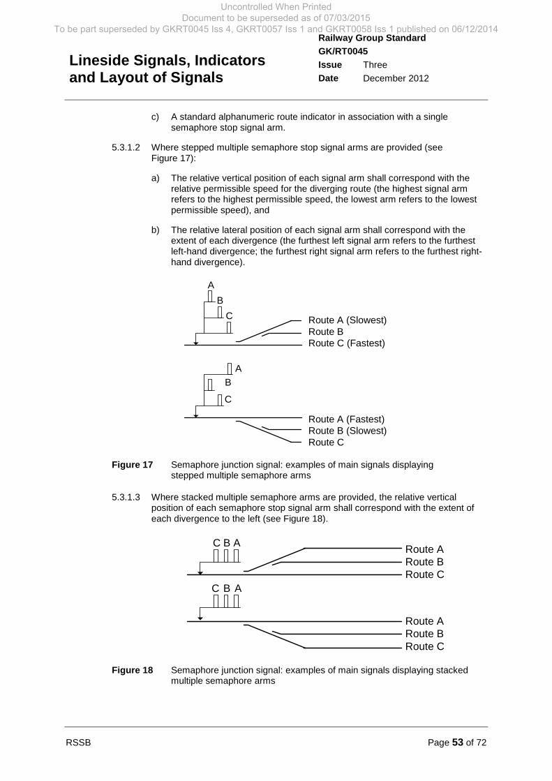
RSSB Page 53 of 72
Railway Group Standard
GK/RT0045
Issue Three
Date December 2012
Lineside Signals, Indicatorsand Layout of Signals
c) A standard alphanumeric route indicator in association with a singlesemaphore stop signal arm.
5.3.1.2 Where stepped multiple semaphore stop signal arms are provided (seeFigure 17):
a) The relative vertical position of each signal arm shall correspond with therelative permissible speed for the diverging route (the highest signal armrefers to the highest permissible speed, the lowest arm refers to the lowestpermissible speed), and
b) The relative lateral position of each signal arm shall correspond with theextent of each divergence (the furthest left signal arm refers to the furthestleft-hand divergence; the furthest right signal arm refers to the furthest right-hand divergence).
Route A (Slowest)Route BRoute C (Fastest)
C
B
A
A
B
C
Route CRoute B (Slowest)Route A (Fastest)
Figure 17 Semaphore junction signal: examples of main signals displayingstepped multiple semaphore arms
5.3.1.3 Where stacked multiple semaphore arms are provided, the relative verticalposition of each semaphore stop signal arm shall correspond with the extent ofeach divergence to the left (see Figure 18).
Route ARoute BRoute C
ABC
Route CRoute BRoute A
ABC
Figure 18 Semaphore junction signal: examples of main signals displaying stackedmultiple semaphore arms
Uncontrolled When Printed Document to be superseded as of 07/03/2015
To be part superseded by GKRT0045 Iss 4, GKRT0057 Iss 1 and GKRT0058 Iss 1 published on 06/12/2014
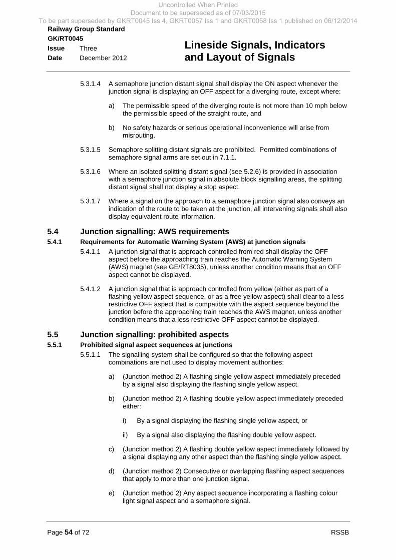
Page 54 of 72 RSSB
Railway Group Standard
GK/RT0045
Issue Three
Date December 2012
Lineside Signals, Indicatorsand Layout of Signals
5.3.1.4 A semaphore junction distant signal shall display the ON aspect whenever thejunction signal is displaying an OFF aspect for a diverging route, except where:
a) The permissible speed of the diverging route is not more than 10 mph belowthe permissible speed of the straight route, and
b) No safety hazards or serious operational inconvenience will arise frommisrouting.
5.3.1.5 Semaphore splitting distant signals are prohibited. Permitted combinations ofsemaphore signal arms are set out in 7.1.1.
5.3.1.6 Where an isolated splitting distant signal (see 5.2.6) is provided in associationwith a semaphore junction signal in absolute block signalling areas, the splittingdistant signal shall not display a stop aspect.
5.3.1.7 Where a signal on the approach to a semaphore junction signal also conveys anindication of the route to be taken at the junction, all intervening signals shall alsodisplay equivalent route information.
5.4 Junction signalling: AWS requirements5.4.1 Requirements for Automatic Warning System (AWS) at junction signals
5.4.1.1 A junction signal that is approach controlled from red shall display the OFFaspect before the approaching train reaches the Automatic Warning System(AWS) magnet (see GE/RT8035), unless another condition means that an OFFaspect cannot be displayed.
5.4.1.2 A junction signal that is approach controlled from yellow (either as part of aflashing yellow aspect sequence, or as a free yellow aspect) shall clear to a lessrestrictive OFF aspect that is compatible with the aspect sequence beyond thejunction before the approaching train reaches the AWS magnet, unless anothercondition means that a less restrictive OFF aspect cannot be displayed.
5.5 Junction signalling: prohibited aspects5.5.1 Prohibited signal aspect sequences at junctions
5.5.1.1 The signalling system shall be configured so that the following aspectcombinations are not used to display movement authorities:
a) (Junction method 2) A flashing single yellow aspect immediately precededby a signal also displaying the flashing single yellow aspect.
b) (Junction method 2) A flashing double yellow aspect immediately precededeither:
i) By a signal displaying the flashing single yellow aspect, or
ii) By a signal also displaying the flashing double yellow aspect.
c) (Junction method 2) A flashing double yellow aspect immediately followed bya signal displaying any other aspect than the flashing single yellow aspect.
d) (Junction method 2) Consecutive or overlapping flashing aspect sequencesthat apply to more than one junction signal.
e) (Junction method 2) Any aspect sequence incorporating a flashing colourlight signal aspect and a semaphore signal.
Uncontrolled When Printed Document to be superseded as of 07/03/2015
To be part superseded by GKRT0045 Iss 4, GKRT0057 Iss 1 and GKRT0058 Iss 1 published on 06/12/2014

RSSB Page 55 of 72
Railway Group Standard
GK/RT0045
Issue Three
Date December 2012
Lineside Signals, Indicatorsand Layout of Signals
f) (Junction method 2) A junction signal that is displaying a flashing aspect anda route indication (a junction signal may display a flashing aspect when thestraight ahead route is set if no route indication is displayed).
g) A free yellow aspect sequence (junction method 4) and a flashing yellowsignal aspect sequence (junction method 2) for different routes from thesame junction signal.
h) A flashing aspect sequence (junction method 2) and a splitting distant signalaspect sequence (junction method 5) for different routes from the samejunction signal.
i) A junction signal displaying both a route indication for a diverging route anda splitting distant signal aspect (junction method 5) for a different junction.
j) (Junction method 5) An inner splitting distant signal shall not display aflashing single yellow aspect.
k) (Junction method 5) An outer splitting distant signal shall not display aflashing double yellow aspect.
Uncontrolled When Printed Document to be superseded as of 07/03/2015
To be part superseded by GKRT0045 Iss 4, GKRT0057 Iss 1 and GKRT0058 Iss 1 published on 06/12/2014
Page 56 of 72 RSSB
Railway Group Standard
GK/RT0045
Issue Three
Date December 2012
Lineside Signals, Indicatorsand Layout of Signals
Part 6 Layout of Signals: Bi-directional Signalling
6.1 Bi-directional signalling6.1.1 Provision of signals
6.1.1.1 Bi-directional lines on multi-track railways shall be signalled using either:
a) Full bi-directional signalling facilities, or
b) Reduced capacity bi-directional signalling facilities.
6.1.1.2 Where full bi-directional signalling facilities are provided for every signal along amultiple track route, there shall be a parallel positioning of signals on adjacentlines in accordance with GE/RT8037.
6.1.1.3 Where reduced capacity bi-directional signalling facilities are provided:
a) Consecutive contraflow direction stop signals shall be spaced no more than10 miles (16 km) apart, and
b) Contraflow direction stop signals and distant signals shall be positioned sothat there is a parallel signal provided for movements in the same directionon adjacent line(s). (GE/RT8037 sets out other requirements for thepositioning of parallel signals.)
6.1.1.4 Where bi-directional facilities are provided on a line signalled using 4-aspectcolour light signals for the predominant (normal) direction of traffic, a 3-aspectsequence shall only be provided for movements in the contraflow direction if alower permissible speed is used to accommodate the reduced signalling brakingdistances between 3-aspect signals that display the yellow and red aspects.
Uncontrolled When Printed Document to be superseded as of 07/03/2015
To be part superseded by GKRT0045 Iss 4, GKRT0057 Iss 1 and GKRT0058 Iss 1 published on 06/12/2014

RSSB Page 57 of 72
Railway Group Standard
GK/RT0045
Issue Three
Date December 2012
Lineside Signals, Indicatorsand Layout of Signals
Part 7 Layout of Signals: Combinations of SignalAspects and Indications
7.1 Combinations of signal aspects (including ERTMS level 2 operatedlines)
7.1.1 Combinations of displayed signal aspects shall be displayed on the same signalonly as set out in Table 24 and Appendix C.
Primary signaltype
Primary signalaspect
Associated signal type(#1)
Associatedsignal:
displayedaspect
Colour lightsignal
Red Subsidiary position light signal OFF
Yellow
Flashing yellow
Double yellow
Flashing doubleyellow
Green
Colour light signal
Splitting distant(see 5.2.6) or
co-acting signal(see 2.2.3) only
Semaphore stopsignal
ON Semaphore main stop signal(#3)
ON
Semaphore distant signal
Semaphore subsidiary or shuntingsignal
Semaphore main stop signal(#3)
OFF
Semaphore subsidiary or shuntingsignal
Position light signal(#2)
OFF Semaphore stop signal(#3)
ON
Semaphore distant signal ON or OFF
Semaphore subsidiary or shuntingsignal
ON
Semaphoreshunt /subsidiary signal
ON Additional arm(s) of multi-armsemaphore shunt / subsidiary signal
ON or OFF
OFF ON
Stop board Stop OFF
#1 excluding co-acting signals
#2 It is not permitted to combine position light signals and semaphore subsidiary signals on the
same signal.
#3 Additional arms on a junction signal
#4 ERTMS level 2 fitted routes only
Table 24 Permitted combinations of signal aspects
Uncontrolled When Printed Document to be superseded as of 07/03/2015
To be part superseded by GKRT0045 Iss 4, GKRT0057 Iss 1 and GKRT0058 Iss 1 published on 06/12/2014
Page 58 of 72 RSSB
Railway Group Standard
GK/RT0045
Issue Three
Date December 2012
Lineside Signals, Indicatorsand Layout of Signals
7.2 Combinations of signal aspects and route indications
7.2.1 Combinations of displayed signal aspects and route indications shall only bedisplayed on the same signal, as set out in Table 25 and Appendix C.
Route indicationtype
Associated signal type Displayed aspect
Position lightjunction indicator
Colour light signal
Performancecategory 2alphanumericroute indicator(SARI)
Colour light signal YellowFlashing yellowDouble yellow
Flashing double yellowGreen
Semaphore main stop signal(#5)
OFF
Position light subsidiarysignal
(#4)OFF
Performancecategory 3alphanumericroute indicator(MARI)
Independent position lightsignal
OFF
Subsidiary position lightsignal
OFF
Semaphore subsidiary orshunting signal
(#5)OFF
Colour light signal(#4)
YellowFlashing yellowDouble yellow
Flashing double yellowGreen
#4 by exception only (see 5.1.1)
#5 an alphanumeric route indicator is an alternative to multiple arms, not an addition
Table 25 Permitted combinations of signals and route indicators
7.3 Signalling indications displayed in association with signal aspects
7.3.1 The combinations of signal indications shall be displayed in accordance withTable 26, subject to the requirements of Appendix C.
7.3.2 Signalling indicators that work in conjunction with signals (for example, OFF, RA)shall not display an indication that is less restrictive than the signal aspect.
Uncontrolled When Printed Document to be superseded as of 07/03/2015
To be part superseded by GKRT0045 Iss 4, GKRT0057 Iss 1 and GKRT0058 Iss 1 published on 06/12/2014
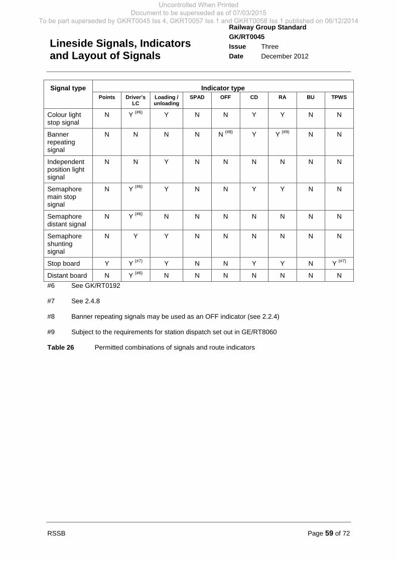
RSSB Page 59 of 72
Railway Group Standard
GK/RT0045
Issue Three
Date December 2012
Lineside Signals, Indicatorsand Layout of Signals
Signal type Indicator type
Points Driver’sLC
Loading /unloading
SPAD OFF CD RA BU TPWS
Colour lightstop signal
N Y(#6)
Y N N Y Y N N
Bannerrepeatingsignal
N N N N N(#8)
Y Y(#9)
N N
Independentposition lightsignal
N N Y N N N N N N
Semaphoremain stopsignal
N Y(#6)
Y N N Y Y N N
Semaphoredistant signal
N Y(#6)
N N N N N N N
Semaphoreshuntingsignal
N Y Y N N N N N N
Stop board Y Y(#7)
Y N N Y Y N Y(#7)
Distant board N Y(#6)
N N N N N N N
#6 See GK/RT0192
#7 See 2.4.8
#8 Banner repeating signals may be used as an OFF indicator (see 2.2.4)
#9 Subject to the requirements for station dispatch set out in GE/RT8060
Table 26 Permitted combinations of signals and route indicators
Uncontrolled When Printed Document to be superseded as of 07/03/2015
To be part superseded by GKRT0045 Iss 4, GKRT0057 Iss 1 and GKRT0058 Iss 1 published on 06/12/2014

Page 60 of 72 RSSB
Railway Group Standard
GK/RT0045
Issue Three
Date December 2012
Lineside Signals, Indicatorsand Layout of Signals
Part 8 Degraded Signalling
8.1 Degraded colour light signalling8.1.1 Aspects to be displayed when a colour light signal light fails
8.1.1.1 Failure of illumination of the most restrictive aspect in a colour light signal shall:
a) Prevent the display of proceed signal aspects towards the defective signal,and
b) Cause the associated distant signal to display its most restrictive aspect.
8.1.1.2 Junction signals shall display a red aspect and be approach controlled from redeither:
a) If the signal that is required to display the associated single flashing yellowaspect fails to commence flashing, or subsequently fails, or
b) If the splitting distant signal immediately preceding the junction signal fails todisplay the correct aspect or subsequently fails.
8.1.2 Proceed on sight signalling
8.1.2.1 The requirements for displaying signal aspects for train movements into signalsections that are affected by lineside signalling failures are set out in GE/RT8071.
Uncontrolled When Printed Document to be superseded as of 07/03/2015
To be part superseded by GKRT0045 Iss 4, GKRT0057 Iss 1 and GKRT0058 Iss 1 published on 06/12/2014
RSSB Page 61 of 72
Railway Group Standard
GK/RT0045
Issue Three
Date December 2012
Lineside Signals, Indicatorsand Layout of Signals
Part 9 Application of this document
9.1 Application - infrastructure managers9.1.1 Scope
9.1.1.1 The requirements in Part 2 of this document apply to all new signal, routeindicator and signalling indicator equipment used for displaying movementauthority information to train crew and station dispatchers.
9.1.1.2 The requirements in Parts 3, 6, 7 and 8 of this document apply to all work thataffects the layout and functionality of signals, whether new or alteration.
9.1.1.3 The requirements in Parts 4, 5 and 8 of this document apply to all work thataffects the layout and functionality of signals, whether new or alteration, exceptthat action to bring existing interlockings into compliance with this standard is notrequired, provided that they were compliant with the standards applicable at thetime that they were brought into service. When it is known, or becomes known,that existing interlockings do not comply with the requirements of this document,action to bring them into compliance is required when the signalling installation asa whole is renewed. It is permissible for a complete interlocking to be renewedon a ‘like-for-like’ basis, that is to say, commensurate with the standards thatwere in force at the time of its original installation.
9.1.1.4 It is permissible for the infrastructure manager to designate specific infrastructureprojects, ongoing when this document comes into force, for which compliancewith the requirements of this document applicable to the design, construction andcommissioning of new or altered infrastructure is not mandatory. Whendesignating such projects, the infrastructure manager shall consider:
a) Its responsibilities under its current safety authorisation.
b) The stage reached by the project at the time this document comes into force(for example, approval in principle).
c) Whether compliance is necessary to ensure compatibility with other parts ofthe infrastructure.
d) Whether compliance is necessary to facilitate safe interworking havingregard to changes to related requirements mandated on anotherinfrastructure manager or a railway undertaking.
e) The economic impact of compliance, but subject to its current safetyauthorisation in relation to the infrastructure in question.
9.1.1.5 Action to bring existing signals, indicators and signalling layouts into compliancewith the requirements of this document is not required.
9.1.2 Exclusions from scope
9.1.2.1 There are no exclusions from the scope specified in 9.1.1 for infrastructuremanagers.
9.1.3 General compliance date for infrastructure managers
9.1.3.1 This Railway Group Standard comes into force and is to be complied with from02 March 2013.
Uncontrolled When Printed Document to be superseded as of 07/03/2015
To be part superseded by GKRT0045 Iss 4, GKRT0057 Iss 1 and GKRT0058 Iss 1 published on 06/12/2014
Page 62 of 72 RSSB
Railway Group Standard
GK/RT0045
Issue Three
Date December 2012
Lineside Signals, Indicatorsand Layout of Signals
9.1.3.2 After the compliance dates, or the date by which compliance is achieved if earlier,infrastructure managers are to maintain compliance with the requirements set outin this Railway Group Standard. Where it is considered not reasonablypracticable to comply with the requirements, authorisation not to comply shouldbe sought in accordance with the Railway Group Standards Code.
9.1.4 Exceptions to general compliance date
9.1.4.1 There are no exceptions to the general compliance date specified in 9.1.3 forinfrastructure managers.
9.2 Application - railway undertakings
9.2.1 There are no requirements applicable to railway undertakings.
9.3 Health and safety responsibilities
9.3.1 Users of documents published by RSSB are reminded of the need to considertheir own responsibilities to ensure health and safety at work and their own dutiesunder health and safety legislation. RSSB does not warrant that compliance withall or any documents published by RSSB is sufficient in itself to ensure safesystems of work or operation or to satisfy such responsibilities or duties.
Uncontrolled When Printed Document to be superseded as of 07/03/2015
To be part superseded by GKRT0045 Iss 4, GKRT0057 Iss 1 and GKRT0058 Iss 1 published on 06/12/2014
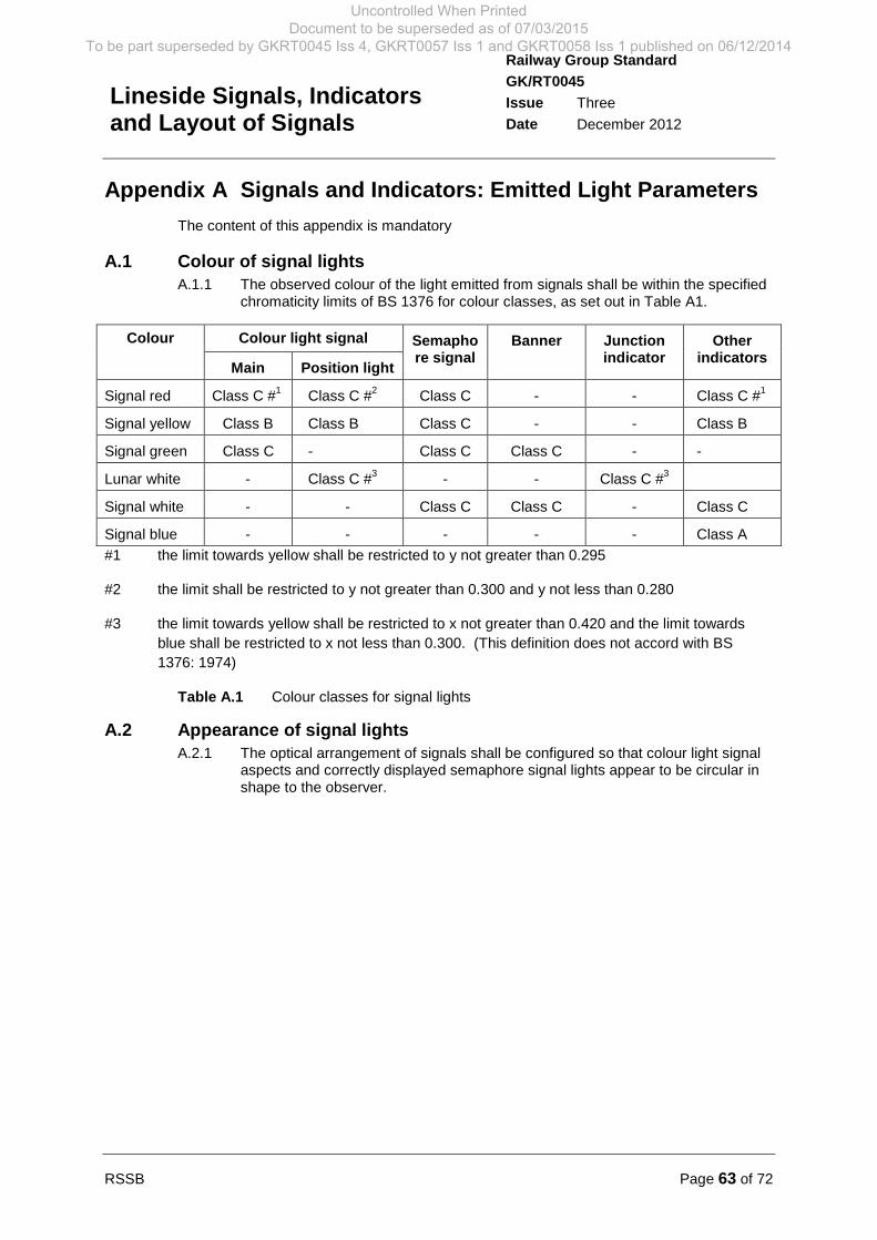
RSSB Page 63 of 72
Railway Group Standard
GK/RT0045
Issue Three
Date December 2012
Lineside Signals, Indicatorsand Layout of Signals
Appendix A Signals and Indicators: Emitted Light Parameters
The content of this appendix is mandatory
A.1 Colour of signal lightsA.1.1 The observed colour of the light emitted from signals shall be within the specified
chromaticity limits of BS 1376 for colour classes, as set out in Table A1.
Colour Colour light signal Semaphore signal
Banner Junctionindicator
Otherindicators
Main Position light
Signal red Class C #1
Class C #2
Class C - - Class C #1
Signal yellow Class B Class B Class C - - Class B
Signal green Class C - Class C Class C - -
Lunar white - Class C #3
- - Class C #3
Signal white - - Class C Class C - Class C
Signal blue - - - - - Class A
#1 the limit towards yellow shall be restricted to y not greater than 0.295
#2 the limit shall be restricted to y not greater than 0.300 and y not less than 0.280
#3 the limit towards yellow shall be restricted to x not greater than 0.420 and the limit towards
blue shall be restricted to x not less than 0.300. (This definition does not accord with BS
1376: 1974)
Table A.1 Colour classes for signal lights
A.2 Appearance of signal lightsA.2.1 The optical arrangement of signals shall be configured so that colour light signal
aspects and correctly displayed semaphore signal lights appear to be circular inshape to the observer.
Uncontrolled When Printed Document to be superseded as of 07/03/2015
To be part superseded by GKRT0045 Iss 4, GKRT0057 Iss 1 and GKRT0058 Iss 1 published on 06/12/2014
Page 64 of 72 RSSB
Railway Group Standard
GK/RT0045
Issue Three
Date December 2012
Lineside Signals, Indicatorsand Layout of Signals
Appendix B Signals and Indicators: Structure Requirements
The requirements specified in this appendix are mandatory
B.1 Colour of signal structuresB.1.1 The external surfaces of colour light signals and indicators shall be coloured
silver or grey, except as follows:
a) The front face of colour light signal heads, backboards and indicators(except for SPAD indicators) shall be matt black, and
b) The front face of SPAD indicators shall be blue to BS 381C shade 109 (see2.4.4).
B.1.2 The colour of semaphore signal sighting boards shall be:
a) Front surface: white.
b) All other surfaces: silver, grey or black.
B.1.3 The colour of semaphore shunting disc signal back blinds shall be white.
B.1.4 The rear of signals constructed as signs shall be grey to BS 381C shade 693.
B.1.5 The external surface colours of signal structures shall be selected:
a) To optimise the visibility of the signal aspects and indications displayed, and
b) So that a red, yellow or green colour cannot be generated or made visibleunder any condition of ambient light.
B.1.6 Mounting brackets, mechanical signal fittings and the rear of semaphore signallamp cases shall be coloured silver, grey or black.
B.2 Signal mounting arrangementsB.2.1 Signals and indicators shall be appropriately and securely mounted so that
displayed signal aspects and indications retain their designed alignment andposition during railway operations in expected environmental conditions andwhen under normally expected static and dynamic loads.
Uncontrolled When Printed Document to be superseded as of 07/03/2015
To be part superseded by GKRT0045 Iss 4, GKRT0057 Iss 1 and GKRT0058 Iss 1 published on 06/12/2014

RSSB Page 65 of 72
Railway Group Standard
GK/RT0045
Issue Three
Date December 2012
Lineside Signals, Indicatorsand Layout of Signals
Appendix C Signals and Indicators: Standard PerformanceCategories
The requirements specified in this appendix are mandatory
C.1 Standard performance categories for signals and indicatorsC.1.1 Signals and indicators shall be readable at the distances and speeds set out in
Table C1, when they can be consistently identified by a person just meeting theeyesight requirements specified in GO/RT3251: Train Driving, in the followingconditions:
a) When viewed along the centre line (+/- 3 degrees) of the spread of light.
b) During daylight and at night.
c) When ambient visibility is 1000 m or better, when measured in accordancewith recognised UK good practice.
d) When viewed from the driving cab.
Performance category Readable distance (m) Readable speed (mph)
1 800 m Up to 125 mph
2 250 m Up to 60 mph #1 #2
3 100 m Up to 15 mph #2
4 400 m Up to 100 mph #2
5 65 m Up to 15mph
#1 Category 2 banner repeating signals and preliminary route indicators shall bereadable up to 125 mph.
#2 For semaphore signals, the category 4 performance category shall apply to both thesignal arm (primarily visible by day) and signal light (primarily visible at night).
Table C.1 Standard performance categories
C.1.2 The spread of light at the angles to the centre line shall be compatible with thereadability and signal sighting requirements specified in GE/RT8037.
C.1.3 Where more than one signal aspect and indication is combined andsimultaneously displayed (see Part 7), the brightness levels of displayed lightsshall be such that no one aspect or indication shall make another unreadablewhen observed from the readable distance of the shorter range aspect orindication.
Uncontrolled When Printed Document to be superseded as of 07/03/2015
To be part superseded by GKRT0045 Iss 4, GKRT0057 Iss 1 and GKRT0058 Iss 1 published on 06/12/2014

Page 66 of 72 RSSB
Railway Group Standard
GK/RT0045
Issue Three
Date December 2012
Lineside Signals, Indicatorsand Layout of Signals
Appendix D Positioning Criteria for Stop Signals on ElectrifiedLines
The requirements specified in this appendix are mandatory
D.1 Positioning stop signals on lines fitted with overhead electrificationsystems
D.1.1 Assessment of train stopping position relative to stop signals and overhead linefeatures
D.1.1.1 During the design of infrastructure positioning an assessment shall be made of:
a) Electric trains formed of rolling stock authorised to operate over the route.
b) The positioning of raised pantographs that interface between the electrictraction unit and the overhead line equipment above, in all permitted trainconfigurations.
c) All permissible stopping distances between a signal, or movement stopmarker, and the front of the train.
d) Proposed or existing location of a stop signal or movement stop markers.
e) Proposed or existing location of overhead line features and associatedpantograph exclusion zones.
f) Requirement for trains to stop at signals in accordance with the GE/RT8000Rule Book.
g) Acceleration of the train from rest, towards the proposed or existing locationof overhead line features and associated pantograph exclusion zones.
D.1.1.2 Duty holders shall cooperate in the provision of the data set out in D.1.1.1. Thisis essential to ensure damage to train or overhead line equipment (OLE)(including potential pantograph damage and dewirement) does not result fromtrain and infrastructure incompatibility.
D.1.2 Position of stop signals relative to OLE neutral sections
D.1.2.1 For trains fitted with a single pantograph, after assessment of the issues set outin D.1.1.1, stop signals, or movement stop markers (or OLE) shall be positionedso that the pantograph does not come to rest in an OLE neutral section or theassociated pantograph exclusion zone.
D.1.2.2 Where a neutral section is situated on the approach to a location where trains arerequired to stop, the stop signal spacing, or movement stop marker spacing, shallbe adequate to ensure that the pantograph does not come to rest in an OLEneutral section or a pantograph exclusion zone.
D.1.2.3 For trains fitted with multiple pantographs, an assessment of the issues set out inD.1.1.1 for trains fitted with a single pantograph, shall first be made. Stopsignals, or movement stop markers (or OLE) shall then be positioned; ensuringnot more than one pantograph comes to rest in an OLE neutral section or theassociated pantograph exclusion zone.
D.1.2.4 Where trains are required to stop on the approach side to the neutral section, thestop signal, or stop signals, or movement stop marker spacing, shall be adequateto ensure:
Uncontrolled When Printed Document to be superseded as of 07/03/2015
To be part superseded by GKRT0045 Iss 4, GKRT0057 Iss 1 and GKRT0058 Iss 1 published on 06/12/2014
RSSB Page 67 of 72
Railway Group Standard
GK/RT0045
Issue Three
Date December 2012
Lineside Signals, Indicatorsand Layout of Signals
a) Subsequent train movement through the overhead line (OHL) neutral sectionis not prevented, and
b) Correct operation of automatic power control systems.
D.1.3 Position of stop signals relative to other critical OLE features
D.1.3.1 Stop signals and OLE shall not be located such that signal sighting is impaired.
D.1.3.2 After assessment of the issues set out in D.1.1.1, stop signals, or movement stopmarkers (or OLE) shall be positioned so that any raised pantograph does notcome to rest, or pass at slow speed, beneath any part of pantograph exclusionzones associated with an:
a) OLE section insulator.
b) OLE switched booster overlap.
c) OLE booster overlap.
d) OLE construction overlap.
D.1.3.3 Where stop signals, or movement stop markers (or OLE) are associated with onlyoccasional diversionary movements, and there is conflict at an OLE overlaplocation, as set out in D.1.3.2, it is permissible for alternative protective provisionsto be adopted where design assessment has shown an alternative location is notreasonably practicable. In every case where alternative protective provisionshave been adopted, a design risk assessment shall be retained and the mitigatingmeasure recorded in the Infrastructure Register.
D.2 Positioning stop signals on lines fitted with conductor railelectrification systems
D.2.1 Assessment of train stopping position relative to stop signals and conductor railelectrification system features
D.2.1.1 During the design of infrastructure positioning, an assessment shall be made of:
a) Electric trains formed of rolling stock authorised to operate over the route.
b) The positioning of collector shoes that interface with third rails and, whenapplicable, fourth rails, in all permitted train configurations.
c) All permissible stopping distances between a signal, or movement stopmarker, and the front of the train.
d) The proposed or existing location of a stop signal or movement stopmarkers.
e) The proposed or existing location of conductor rail gaps.
f) The proposed or existing arrangement for remote switching betweensections of conductor rail.
g) The requirement for trains to stop at signals in accordance with theGE/RT8000 Rule Book.
h) Acceleration of the train from rest, towards the proposed or existing locationof conductor rail gaps.
Uncontrolled When Printed Document to be superseded as of 07/03/2015
To be part superseded by GKRT0045 Iss 4, GKRT0057 Iss 1 and GKRT0058 Iss 1 published on 06/12/2014
Page 68 of 72 RSSB
Railway Group Standard
GK/RT0045
Issue Three
Date December 2012
Lineside Signals, Indicatorsand Layout of Signals
D.2.1.2 Duty holders shall cooperate in the provision of data set out in D.2.1.1. This isessential to ensure trains are not gapped and risk of fire, risk of arc inducedinjury, or damage to trains or fixed infrastructure, does not result from train andinfrastructure incompatibility.
D.2.2 Position of stop signals relative to conductor rail gaps
D.2.2.1 After assessment of the issues set out in D.2.1.1, stop signals, or movement stopmarkers (or conductor rails) shall be positioned to ensure any conductor railcollector shoes do not come to rest in a conductor rail gap.
D.2.2.2 After assessment of the issues set out in D.2.1.1, stop signals, or movement stopmarkers (or conductor rails) shall be positioned to ensure conductor rail collectorshoes do not bridge a gap between two (or more) sections of conductor rail thatcan be isolated from each other by remote switching.
Uncontrolled When Printed Document to be superseded as of 07/03/2015
To be part superseded by GKRT0045 Iss 4, GKRT0057 Iss 1 and GKRT0058 Iss 1 published on 06/12/2014
RSSB Page 69 of 72
Railway Group Standard
GK/RT0045
Issue Three
Date December 2012
Lineside Signals, Indicatorsand Layout of Signals
Definitions
Cautionary aspect / cautionary aspect sequence
The signal aspects displayed by the signals, either on the approach to a junction signaldisplaying a restrictive aspect, or any signal displaying a stop aspect.
Centre line (of signal or indicator)
The line (usually extending out perpendicularly from the face of a signal) forming the opticalaxis of the beam.
Chromaticity (for lights only)
The co-ordinates of a colour that may be plotted on the 1931 CIE (CommissionInternationale de l’Eclairage) chromaticity diagram to graphically represent the colour.
Correctly displayed (signal aspect or indication)
The accurate display of movement authority information so that the railway operator is ableto observe the information that the system is designed to display.
Displayed / displaying (signal aspect or indication)
Visual presentation (by means of lineside signalling equipment) of movement authorityinformation to a railway operator (typically train crew or station staff).
Distant / inner distant signal
A signal that displays the cautionary aspect approaching a stop signal.
Diverging junction
A junction that incorporates facing points and signalled routes in more than one facingdirection.
Diverging route
Any route at a facing junction that is not designated the ‘straight ahead route’.
Independent single line
A line that forms a distinct single line route and is signalled for train movements in bothdirections.
Junction distant signal
A signal that displays the cautionary signal aspect on the approach to a junction signal.
Junction outer-distant signal
A signal that displays the first cautionary aspect in a sequence of cautionary aspects on theapproach to a junction signal.
Junction signal
A colour light signal or semaphore stop signal that is configured to display signal aspectsfor more than one route at a diverging junction.
Lower quadrant
A term applied to a semaphore signal, in which the OFF aspect is displayed when the left-hand end of the signal arm is lowered below the horizontal.
Movement authority (MA)
The authority given by a signaller (or ground frame operator), issued via the signallingsystem to the driver, which is the authority to move the train within defined limits.
Uncontrolled When Printed Document to be superseded as of 07/03/2015
To be part superseded by GKRT0045 Iss 4, GKRT0057 Iss 1 and GKRT0058 Iss 1 published on 06/12/2014
Page 70 of 72 RSSB
Railway Group Standard
GK/RT0045
Issue Three
Date December 2012
Lineside Signals, Indicatorsand Layout of Signals
OFF aspect
Any signal aspect that is less restrictive than an ON aspect displayed by a particular signal.
ON aspect
The most restrictive signal aspect that can be displayed by a particular signal.
Outer distant signal
A signal that displays the first cautionary aspect in a sequence of cautionary aspects on theapproach to a stop signal.
Pantograph exclusion zone
The length of track relative to a defined overhead line equipment feature (for example, anoverlap) within which the pantograph of an electric train does not touch the contact wirewhen the train is stationary or moving at a slow speed in order to prevent electrical arcing.
Reading through
The erroneous observance and response to a signal aspect beyond the signal that thedriver is required to observe.
Signal
Fixed infrastructure equipment that is positioned at the lineside and used by theinfrastructure manager to display information about movement authorities to railwayundertakings.
Signal light
The part of a signal that emits an illuminated form of visual indication. A signal aspect canincorporate one or more signal lights.
Signal primary identification
The signal identification that is displayed at the signal when a signal has more than onenumbered operating device.
Signal red, signal yellow, signal green, signal blue, signal white, lunar white
Throughout this document these light colour descriptions correspond to the appropriatecolour definition in Appendix B of this document.
Signalling indication
A form of operational information that is displayed by lineside indicators.
Stop signal
Any signal that can display a stop aspect.
Straight ahead route
The non-diverging (and usually the fastest) route at a diverging junction.
Synchronism (for lights only)
The illumination of multiple flashing lights, so that all of the lights are displayed at the sametime.
Upper quadrant
A term applied to a semaphore signal, banner repeating signal or position light signal, inwhich the OFF aspect is displayed when the left-hand end of the signal arm is raised abovethe horizontal.
Uncontrolled When Printed Document to be superseded as of 07/03/2015
To be part superseded by GKRT0045 Iss 4, GKRT0057 Iss 1 and GKRT0058 Iss 1 published on 06/12/2014

RSSB Page 71 of 72
Railway Group Standard
GK/RT0045
Issue Three
Date December 2012
Lineside Signals, Indicatorsand Layout of Signals
Abbreviations and acronymsAWS
Automatic Warning System
LED
Light emitting diode
OHL
Overhead line
OLE
Overhead line equipment
SPAD
Signal passed at danger
TPWS
Train Protection and Warning System
Uncontrolled When Printed Document to be superseded as of 07/03/2015
To be part superseded by GKRT0045 Iss 4, GKRT0057 Iss 1 and GKRT0058 Iss 1 published on 06/12/2014

Page 72 of 72 RSSB
Railway Group Standard
GK/RT0045
Issue Three
Date December 2012
Lineside Signals, Indicatorsand Layout of Signals
References
The Catalogue of Railway Group Standards gives the current issue number and status ofdocuments published by RSSB. This information is also available fromwww.rgsonline.co.uk.
RGSC 01 Railway Group Standards Code
RGSC 02 The Standards Manual
Documents referenced in the textRailway Group Standards
GC/RT5021 Track System Requirements
GE/RT8000 Rule Book
GE/RT8030 Requirements for the Train Protection and WarningSystem (TPWS)
GE/RT8035 Automatic Warning System (AWS)
GE/RT8037 Signal Positioning and Visibility
GE/RT8071 Control Facilities for use during Lineside SignallingFailures
GI/RT7006 Prevention and Mitigation of Overruns – Risk Assessment
GK/RT0044 Controls for Signalling a Train onto an Occupied Line
GK/RT0077 Ground Frames and Shunters’ Releases (to be publishedmid 2013)
GK/RT0051 Single Line Control
GK/RT0075 Lineside Signal Spacing and Speed Signage
GK/RT0192 Level Crossing Interface Requirements
GK/RT0212 Signalling Lockout Systems to Protect RailwayUndertaking Personnel
GO/RT3215 Requirements for the Weekly Operating Notice, PeriodicalOperating Notice and Sectional Appendix
RSSB documents
GK/GN0645 Guidance on Lineside Signals, Indicators and Layout ofSignals
Other references
BS 381C: Colour Chart
BS 1376, 1974: Specification for Colour of Light Signals
BS 873, Part 6: Specification for retroreflective and non-retroreflective signs
Traffic Signs and Signals Guidance, published by the Department for Transport
Uncontrolled When Printed Document to be superseded as of 07/03/2015
To be part superseded by GKRT0045 Iss 4, GKRT0057 Iss 1 and GKRT0058 Iss 1 published on 06/12/2014