Embed Size (px)
Citation preview

Linear drives DGPI/DGPIL, with integrated displacement encoder

Subject to change – 2013/112 � Internet: www.festo.com/catalogue/...
Cylinders with displacement encoderProduct range overview
Function Type Brief description
Drives Rodless
DDLI • Without guide
• With contactless measuring displacement encoder
• Based on linear drive DGC-K
• Supply ports on end face
• System product for handling and assembly technology
DGCI • With guide
• With contactless measuring displacement encoder
• Based on linear drive DGC
• Supply ports optionally on end face or front
• System product for handling and assembly technology
DGPI/DGPIL Do not use for new projects!
• With or without guide
• With contactless measuring displacement encoder, integrated
• Wide range of options for mounting on drives
• System product for handling and assembly technology
DGP/DGPL Do not use for new projects!
• With or without guide
• With potentiometer or contactless measuring displacement encoder, attached
• With clamping unit
• Wide range of options for mounting on drives
With piston rod
DNCI • With contactless measuring displacement encoder
• Various piston rod variants
• Standards-based cylinder to ISO 15552
DIN
DDPC • With contactless measuring displacement encoder
• Various piston rod variants
• Standards-based cylinder to ISO 15552
DIN
DNC/DSBC • With attached potentiometer MLO-LWG
• Various piston rod variants
• Standards-based cylinder to ISO 15552
DIN
Swivel
modules
Swivel modules
DSMI • Based on swivel modules DSM
• Integrated rotary potentiometer
• Compact design
• Wide range of mounting options

2013/11 – Subject to change 3� Internet: www.festo.com/catalogue/...
Cylinders with displacement encoderProduct range overview
Piston∅ Stroke/swivel angle Suitable
for positioning with for end-position controller for use as a measuring
cylinder[mm/°] CPX-CMAX SPC200 CPX-CMPX SPC11
Rodless
25, 32, 40 100, 160, 225, 300, 360,
450, 500, 600, 750, 850,
1000, 1250, 1500, 1750,
2000� � � � �
18, 25, 32,
40, 63
100, 160, 225, 300, 360,
450, 500, 600, 750, 850,
1000, 1250, 1500, 1750,
2000� � � � �
25, 32, 40,
50, 63
225, 300, 360, 450, 500,
600, 750, 1000, 1250,
1500, 1750, 2000 � � � � �
25, 32, 40,
50, 63
225, 300, 360, 450, 500,
600, 750, 1000, 1250,
1500, 1750, 2000 – � – � �
With piston rod
32, 40, 50,
63
10 … 2000
– – – – �
100 … 750
� � � � –
80, 100 10 … 2000
– – – – �
100 … 750
� � � � –
32, 40, 50,
63, 80
100, 150, 225, 300, 360,
450, 600, 750
� � � � �
Swivel modules
25, 40, 63 270
� � � � �
Subject to change – 2013/114 � Internet: www.festo.com/catalogue/...
Cylinders with displacement encoderFeatures
Servopneumatic drive technology
Positioning and Soft Stop applica-
tions as an integral component of the
valve terminal CPX – the modular
peripheral system for decentralised
automation tasks.
The modular design means that
valves, digital inputs and outputs,
positioning modules and end-position
controllers, as appropriate to the
application, can be combined in
almost any way on the CPX terminal.
Advantages:
• Pneumatics and electrics – control
and positioning on one platform
• Innovative positioning technology –
piston rod drives, rodless drives,
rotary drives
• Actuation via fieldbus
• Remote maintenance, remote
diagnostics, web server, SMS and
e-mail alerts are all possible via
TCP/IP
• Modules can be quickly exchanged
and expanded without altering the
wiring
Axis controller CPX-CMAX Technical data� Internet: cpx-cmax
Free choice:
Position and force control, directly
actuated or selected from one of
64 configurable position sets.
If you are looking for something
more: the configurable function for
switching to the next set enables
simple functional sequences to be
realised with the axis controller
CPX-CMAX.
All stations are recognised as:
the auto-identification function
identifies each participant with its
device data on the controller
CPX-CMAX.
Also included:
The functional scope of the control-
ler CPX-CMAX includes actuation of
a brake or clamping unit via the
proportional directional control
valve VPWP.
Up to 8 modules (max. 8 axes) can
be operated in parallel and
independently of each other.
Commissioning via FCT (Festo
configuration software) or via
fieldbus: no programming, only
configuration.
Advantages:
• Greater flexibility
• OEM friendly – commissioning
also via fieldbus
• Easy installation and fast
commissioning
• Cost-effective
• You program the system in your
PLC environment
2013/11 – Subject to change 5� Internet: www.festo.com/catalogue/...
Cylinders with displacement encoderFeatures
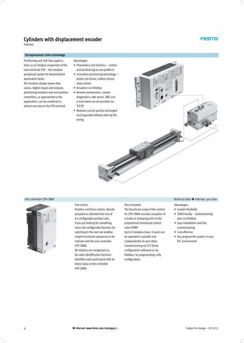
End-position controller CPX-CMPX Technical data� Internet: cpx-cmpx
Fast travel between the mechanical
end stops of the cylinder, stopping
gently and without impact in the
end position.
Fast commissioning via control
panel, fieldbus or handheld unit.
Improved control of downtime.
Actuation of a brake or clamping
unit via the proportional directional
control valve VPWP is an integral
part of the controller CMPX.
Depending on the fieldbus chosen,
up to 9 end-position controllers can
be actuated on the CPX terminal.
All system data can be read and
written via the fieldbus, including,
for example, the mid positions.
Advantages:
• Greater flexibility
• OEM friendly – commissioning
also via fieldbus
• Easy installation and fast
commissioning
• Cost-effective
– up to 30% faster cycle rates
– significantly reduced system
vibration
• Improved work ergonomics
thanks to significantly reduced
noise level
• The extended diagnostics help to
reduce the service time of the
machine
Proportional directional control valve VPWP Technical data� Internet: vpwp
The 5/3-way proportional direc-
tional control valve for applications
with Soft Stop and pneumatic
positioning.
Fully digitalised – with integrated
pressure sensors, with new
diagnostic functions.
In sizes 4, 6, 8 and 10.
Flow rate of 350, 700, 1400 and
2000 l/min.
With switching output for actuating
a brake.
Coloured supply ports.
Pre-assembled cables guarantee
faultless and fast connection with
the controllers CPX-CMPX and
CPX-CMAX.
Advantages:
• Easy installation and fast
commissioning
• Reduction of system downtimes
thanks to the new diagnostic
options
• With switching output for
actuating a brake/clamping unit
Measuring module CPX-CMIX Technical data� Internet: cpx-cmix
Fully digital data acquisition and
transmission means that pneumatic
cylinders can be used as sensors.
With very high repetition accuracy
and incorporating both analogue
and digital measuring sensors.
Suitable for the linear drive DGCI
with displacement encoder for
measuring absolute values, for the
piston rod drive DNCI/DDPC with
incremental displacement encoder
or even for a potentiometer of the
type MLO.
Advantages:
• All process steps can be docu-
mented, which improves quality
• An adjustable contact force (via
pressure regulator) increases the
precision of the "displacement
sensor"
• With displacement encoders for
measuring absolute values, the
actual position is immediately
available after the system is
switched on
Subject to change – 2013/116 � Internet: www.festo.com/catalogue/...
Cylinders with displacement encoderDrive options
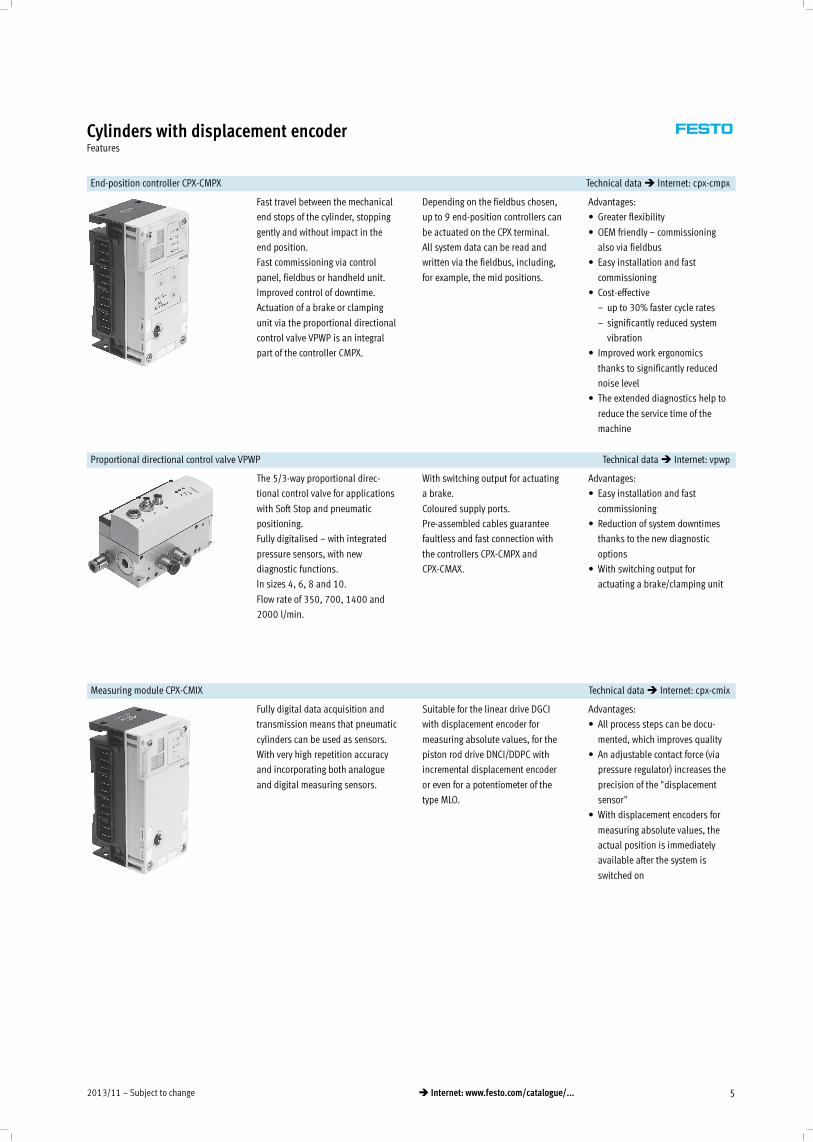
System with linear drive DDLI, DGCI Technical data� Internet: ddli or dgci
1 Controller module CPX-CMPX or CPX-CMAX
2 Proportional directional control valve VPWP
3 Linear drive DDLI, DGCI with displacement encoder
6 Connecting cable KVI-CP-3-…
1 2 3
6
• Pneumatic rodless linear drive
with displacement encoder, with
or without recirculating ball
bearing guide
• Displacement encoder with
absolute and contactless
measurement
• Diameters:
– DGCI: 18 … 63 mm
– DDLI: 25 … 40 mm
• Stroke: 100 … 2000 mm in fixed
lengths
• Range of applications: Soft Stop
and pneumatic positioning
• Loads from 1 … 180 kg
• No sensor interface required
Advantages:
• Complete drive unit
• DDLI for easy connection to
customer's guide system
• Excellent running characteristics
• For fast and accurate positioning
down to ±0.2 mm (only with axis
controller CPX-CMAX)
System with linear drive DGPI, DGPIL or displacement encoder MME-MTS Technical data� Internet: dgpi
1 Controller module CPX-CMPX or CPX-CMAX
2 Proportional directional control valve VPWP
3 Linear drive DGPI, DGPIL with displacement encoder
6 Connecting cable KVI-CP-3-…
9 NEBP-M16W6-K-2-M9W5
1 2 3
6 9
• Pneumatic rodless linear drive
with displacement encoder, with
or without recirculating ball
bearing guide
• Displacement encoder with
absolute and contactless
measurement
• Diameter: 25 … 63 mm
• Stroke: 225 … 2000 mm in fixed
lengths
• Range of applications: Soft Stop
and pneumatic positioning
• Loads from 2 … 180 kg
• No sensor interface required
Advantages:
• Complete drive unit
• DGPI for easy connection to
customer's guide system
• Excellent running characteristics
• For fast and accurate positioning
down to ±0.2 mm (only with axis
controller CPX-CMAX)
System with standard cylinder DNCI, DDPC Technical data� Internet: dnci
1
52
3
6
6
1 Controller module CPX-CMPX or CPX-CMAX
2 Proportional directional control valve VPWP
3 Standard cylinder DNCI, DDPC with displacement encoder
5 Sensor interface CASM-S-D3-R7
6 Connecting cable KVI-CP-3-…
• Standard cylinder with integrated
displacement encoder, conforms
to DIN ISO 6432, VDMA 24 562,
NF E 49 003.1 and Uni 10 290
• Displacement encoder with
contactless and incremental
measuring
• Diameter: 32 … 100 mm
• Stroke: 100 … 750 mm
• Range of applications: Soft Stop
and pneumatic positioning
• Loads from 3 … 450 kg and a
matching sensor interface
CASM-S-D3-R7
• Pre-assembled cables guarantee
faultless and fast electrical
connection
Advantages:
• Compact drive unit
• Can be used universally
• Also with guide unit
• For fast and accurate positioning
up to ±0.5 mm (only with axis
controller CPX-CMAX)
2013/11 – Subject to change 7� Internet: www.festo.com/catalogue/...
Cylinders with displacement encoderDrive options
System with swivel module DSMI Technical data� Internet: dsmi
1
42
3
6
6
1 Controller module CPX-CMPX or CPX-CMAX
2 Proportional directional control valve VPWP
3 Swivel module DSMI with displacement encoder
4 Sensor interface CASM-S-D2-R3
6 Connecting cable KVI-CP-3-…
7 Connecting cable NEBC-P1W4-K-0,3-N-M12G5
7
• Swivel module DSMI with
integrated displacement encoder
• Identical design to pneumatic
swivel module DSM
• Absolute displacement encoder
based on a potentiometer
• Swivel range of 0 … 270°
• Size: 25, 40, 63
• Max. torque: 5 … 40 Nm
• Range of applications: Soft Stop
and pneumatic positioning
• Mass moments of inertia from
15 … 6000 kgcm2 and a
matching sensor interface
CASM-S-D2-R3
• Pre-assembled cables guarantee
faultless and fast connection with
the proportional directional
control valve VPWP
Advantages:
• Complete drive unit, compact,
can be used immediately
• High angular acceleration
• With adjustable fixed stops
• For fast and accurate positioning
down to ±0.2° (only with axis
controller CPX-CMAX)
System with potentiometer Technical data� Internet: casm
7
8
6
1 Controller module CPX-CMPX or CPX-CMAX
2 Proportional directional control valve VPWP
4 Sensor interface CASM-S-D2-R3
6 Connecting cable KVI-CP-3-…
7 Connecting cable NEBC-P1W4-K-0,3-N-M12G5
8 Connecting cable NEBC-A1W3-K-0,4-N-M12G5
42
1
6
• Attachable potentiometers with
absolute measurement, with high
degree of protection
• With connecting rod or moment
compensator
• Measuring range:
100 … 2000 mm
• Pre-assembled cables guarantee
faultless and fast connection with
the sensor interface CASM
• Range of applications: Soft Stop
and pneumatic positioning with
cylinder∅ 25 … 80 mm,
e.g. DNC or DSBC
• Loads from 1 … 300 kg
Advantages:
• Easy installation and fast
commissioning
• Cost-effective
• Can also be used in harsh
ambient conditions
• Variety of drives: CPX-CMPX and
CPX-CMAX also support cylinders
with external displacement
encoder

Subject to change – 2013/118 � Internet: www.festo.com/catalogue/...
Cylinders with displacement encoderDrive options
System components for Soft Stop systems with end-position controller CPX-CMPX
Linear drive Standard cylinder Swivel module Displacement encoder � Page/
InternetDDLI/DGCI DGPI DNCI, DDPC DSMI MLO-LWG/-TLF MME-MTS
End-position controller
CPX-CMPX� � � � � � cmpx
Prop. directional control valve
VPWP� � � � � � vpwp
Sensor interface
CASM-S-D2-R3– – – � � – casm
Sensor interface
CASM-S-D3-R7– – � – – – casm
Connecting cable
KVI-CP-3-…� � � � � � kvi
Connecting cable
NEBC-P1W4-…– – – � � / – – nebc
Connecting cable
NEBC-A1W3-…– – – – – /� – nebc
Connecting cable
NEBP-M16W6-…– � – – – � nebp
System components for pneumatic positioning systems with axis controller CPX-CMAX
Linear drive Standard cylinder Swivel module Displacement encoder � Page/
InternetDDLI/DGCI DGPI DNCI, DDPC DSMI MLO-LWG/-TLF MME-MTS
Axis controller
CPX-CMAX� � � � � � cmax
Prop. directional control valve
VPWP� � � � � � vpwp
Sensor interface
CASM-S-D2-R3– – – � � – casm
Sensor interface
CASM-S-D3-R7– – � – – – casm
Connecting cable
KVI-CP-3-…� � � � � � kvi
Connecting cable
NEBC-P1W4-…– – – � � / – – nebc
Connecting cable
NEBC-A1W3-…– – – – – /� – nebc
Connecting cable
NEBP-M16W6-…– � – – – � nebp
System components for measuring cylinders with measuring module CPX-CMIX
Linear drive Standard cylinder Swivel module Displacement encoder � Page/
InternetDDLI/DGCI DGPI DNCI, DDPC DSMI MLO-LWG/-TLF MME-MTS
Measuring module
CPX-CMIX-M1-1� � � � � � cmix
Sensor interface
CASM-S-D2-R3– – – � � – casm
Sensor interface
CASM-S-D3-R7– – � – – – casm
Connecting cable
KVI-CP-3-…(�)1) (�)1) � � � (�) kvi
Connecting cable
NEBC-P1W4-…– – – � � / – – nebc
Connecting cable
NEBC-A1W3-…– – – – – /� – nebc
Connecting cable
NEBP-M16W6-…– � – – – � nebp
1) As an extension
2013/11 – Subject to change 9� Internet: www.festo.com/catalogue/...
Cylinders with displacement encoderOverview
Individual components for positioning
With axis controller SPC200 With end-position controller SPC11
� Internet: spc200 � Internet: spc11
1 Axis controller SPC200
2 Proportional directional control
valve MPYE
3 Linear drive DGPI, DGPIL
4 Axis interface SPC-AIF-MTS
6 Connecting cable
KSPC-AIF-…
7 Connecting cable
KMPYE-AIF-…
1
6
4
7
2
3
2 Proportional directional control
valve MPYE
3 Linear drive DGPI, DGPIL
5 End-position controller
SPC11-MTS-AIF
7 Connecting cable
KMPYE-AIF-…
2
7
5
3
DGPI, without guide 10
• Piston∅ 25 … 63 mm
• Stroke 225 … 2,000 mm
• Standard moment compensator
• Low characteristic load values
• Supply ports on both sides
DGPIL, with recirculating ball bearing guide 24
• Piston∅ 25 … 63 mm
• Stroke 225 … 2,000 mm
• Standard slide
• High characteristic load values
• Supply ports on both sides

Subject to change – 2013/1110 � Internet: www.festo.com/catalogue/...
Linear drives DGPI, with integrated displacement encoderPeripherals overview
1
2
3
4
Variants and accessories
Type Brief description � Page/Internet
1 Slot cover
B/S
For protecting against the ingress of dirt 41
2 Slot nut
Y
For mounting attachments 41
3 Central support
M
For mounting the axis 38
4 Foot mounting
F
For mounting the axis 38
Do not use for new designs!
-U- Type discontinued

2013/11 – Subject to change 11� Internet: www.festo.com/catalogue/...
Linear drives DGPI, with integrated displacement encoderType codes
DGPI – 25 – 500 – PPV – AIF – GK – AV – D2 – 4BYF
Type
DGPI Linear drive
Piston∅ [mm]
Stroke [mm]
Cushioning
PPV Adjustable at both ends
Displacement encoder
AIF CAN axis interface
Basic design
GK Standard slide
Connection position for displacement
encoder and compressed air
AH Connections at rear
AU Connections underneath
AV Connections at front
Supply port
D2 Supply port at both ends
Accessories enclosed separately
…S Slot cover for sensor slot
…B Slot cover for mounting slot
…Y Slot nut for mounting slot
…M Central support
…F Foot mounting
Do not use for new designs!
-U- Type discontinued
Subject to change – 2013/1112 � Internet: www.festo.com/catalogue/...
Linear drives DGPI, with integrated displacement encoderTechnical data
Function
-N- Diameter
25 … 63 mm
-T- Stroke length
225 … 2,000 mm
General technical data
Piston∅ 25 32 40 50 63
Design Piston
Moment compensator
Profile barrel
Mode of operation Double-acting
Operating medium1) Compressed air according to ISO 8573-1:2010 [6:4:4]
Note about the operating/pilot medium Lubricated operation not possible
Pressure dew point 10 °C below ambient temperature/temperature of medium
Cushioning Adjustable at both ends
Cushioning length [mm] 18 20 30
Position sensing Integrated displacement encoder
Measuring principle Digital, magnetostrictive, non-contacting and absolute measurement
Type of mounting Foot mounting
Stroke2)3) [mm] 225; 300; 360; 450; 500; 600; 750; 1,000; 1,250; 1,500; 1,750; 2,000
Pneumatic connection Gx G¼ Gy
Electrical connection 6-pin round plug to DIN 45322
1) The proportional directional control valve MPYE used requires the characteristic values.
2) Note stroke reduction in combination with SPC200.
3) Supply of compressed air to each end of the cylinder (feature D2) is absolutely essential for Soft Stop SPC11 and axis controller SPC200 as of a length of 500 mm.
Forces [N] and impact energy [Nm]
Piston∅ 25 32 40 50 63
Theoretical force at 6 bar 295 483 754 1,178 1,870
Max. impact energy in the end positions1) 0.1 0.2 0.4 0.8 0.8
1) Cushioning PPV must be completely open for applications with Soft Stop SPC11 and axis controller SPC200.
vperm. =
2 x Eperm.
mdead + mload
�
mload =
2 x Eperm.
v2− mdeadMaximum permissible load:
Permissible impact velocity:vperm. Permissible impact velocity
Eperm. Maximum impact energy
mdead Moving mass (drive)
mload Moving effective load
-H- Note
These specifications represent the
maximum values that can be
achieved. Note the maximum
permissible impact energy.
Do not use for new designs!
-U- Type discontinued
2013/11 – Subject to change 13� Internet: www.festo.com/catalogue/...
Linear drives DGPI, with integrated displacement encoderTechnical data
Positioning characteristics with axis controller SPC200
Piston∅ 25 32 40 50 63
Repetition accuracy [mm] � 14
Mounting position Any
Minimum load, horizontal1) [kg] 2 3 5 8 12
Maximum load, horizontal1) [kg] 30 45 75 120 180
Minimum load, vertical1) [kg] 2 3 5 8 12
Maximum load, vertical1) [kg] 10 15 25 40 60
Minimum travel speed [m/s] 0.05
Maximum travel speed [m/s] 3
Typical positioning time, long stroke2) [s] 0.75/1.20 0.85/1.20 0.75/1.20 0.95/1.25 0.90/1.20
Typical positioning time, short stroke3) [s] 0.40/0.60 0.45/0.60 0.40/0.60 0.50/0.65 0.50/0.65
Minimum positioning stroke4) [%] 3
Stroke reduction5) [mm] 25 35
Recommended proportional directional control valve � 42
1) Load = effective load + mass of all moving parts on the drive
2) At 6 bar, horizontal mounting position, DGPL-XX-1250, 1,000 mm travel at min./max. load
3) At 6 bar, horizontal mounting position, DNCM-XX-1250, 100 mm travel at min./max. load
4) In relation to the maximum stroke of the drive, but never more than 20 mm
5) The stroke reduction must be maintained on each side of the drive, the max. positionable stroke is therefore: stroke – 2x stroke reduction
Positioning characteristics with end-position controller SPC11
Piston∅ 25 32 40 50 63
Repetition accuracy of a mid-position1) [mm] ±2
Mounting position Any
Minimum load, horizontal2) [kg] 2 3 5 8 12
Maximum load, horizontal2) [kg] 30 45 75 120 180
Minimum load, vertical2) [kg] 2 3 5 8 12
Maximum load, vertical2) [kg] 10 15 25 40 60
Travel time [s] � SoftStop sizing software:� www.festo.com
Recommended proportional directional control valve � 42
1) In the stroke range from 225 … 2,000 mm
2) Load = effective load + mass of all moving parts on the drive
Operating and environmental conditions
Piston∅ 25 32 40 50 63
Operating pressure1) [bar] 4 … 8
Ambient temperature [°C] –10 … +60
Vibration resistance To DIN/IEC 68 Parts 2 – 6, severity level 1
Continuous shock resistance To DIN/IEC 68 Parts 2 – 27, severity level 1
CE marking (see declaration of conformity) To EU EMC Directive
Protection class (displacement encoder) IP65 to IEC 60 529
Corrosion resistance class CRC2) 1
1) Only applies to applications with Soft Stop SPC11 and axis controller SPC200
2) Corrosion resistance class 1 according to Festo standard 940 070
Components subject to low corrosion stress. Transport and storage protection. Parts that do not have primarily decorative surface requirements, e.g. in internal areas that are not visible or behind covers.
Weight [g]
Piston∅ 25 32 40 50 63
Basic weight 1,540 2,150 3,500 6,980 10,600
Additional weight per 10 mm stroke 38 43 59 130 168
Moving load 180 314 551 1,045 1,775
Do not use for new designs!
-U- Type discontinued
Subject to change – 2013/1114 � Internet: www.festo.com/catalogue/...
Linear drives DGPI, with integrated displacement encoderTechnical data
Electrical data – Displacement encoder
Power supply [V DC] 24 (–15/+25%)
Maximum current consumption [mA] 90
Resolution [mm] ≤ 0.01
Independent linearity1) Maximum [%] 0.02
Temperature coefficient [ppm/°K] ≤ 15
Interface Digital, CAN with protocol: SPC-AIF
1) Minimum ±50 µm
Materials
Sectional view
1 2 3 4 5
Drive
1 End cap Anodised aluminium
2 Profile Anodised aluminium
3 Cover strip Corrosion-resistant steel
4 Moment compensator Anodised aluminium
5 Displacement encoder housing Anodised aluminium
– Seals Nitrile rubber, polyurethane
-H- Note
More technical data
� Internet: dpgl
Repetition accuracy
Tolerance t [mm] as a function of stroke l [mm]
Horizontal Vertical
1 With analogue displacement encoder
2 With digital displacement encoder
Do not use for new designs!
-U- Type discontinued
2013/11 – Subject to change 15� Internet: www.festo.com/catalogue/...
Linear drives DGPI, with integrated displacement encoderTechnical data
Characteristic load values
The indicated forces and torques
refer to the centre line of the internal
diameter of the profile barrel.
These values must not be exceeded
during dynamic operation. Special
attention must be paid to the
deceleration phase.
If the drive is simultaneously subjec-
ted to several of the indicated forces
and torques, the following equation
must be satisfied in addition to the
indicated maximum loads:
0, 4×Fz
Fzmax.+
MxMxmax.
+My
Mymax.+ 0, 2×
MzMzmax.
≤ 1
MzMzmax.
≤ 1Fz
Fzmax.≤ 1
Permissible forces and torques
Piston∅ 25 32 40 50 63
Fymax. [N] – – – – –
Fzmax. [N] 330 480 800 1,200 1,600
Mxmax. [Nm] 1 2 4 7 8
Mymax. [Nm] 20 40 60 120 120
Mzmax. [Nm] 3 5 8 15 24
Maximum permissible support span l as a function of force F
The axis may need to be supported
with central supports MUP in order to
limit deflection in the case of large
strokes. The following graphs can be
used to determine the maximum per-
missible support span l as a function
of force F acting on the axis.
Force on the surface of the slide
FF F
Maximum support span l (without central support) as a function of force F
Piston∅ 25 … 40 Piston∅ 50/63
l [mm]
F[N]
I [mm]
F[N]
DGPI...-63
DGPI...-50
Do not use for new designs!
-U- Type discontinued
Subject to change – 2013/1116 � Internet: www.festo.com/catalogue/...
Linear drives DGPI, with integrated displacement encoderTechnical data
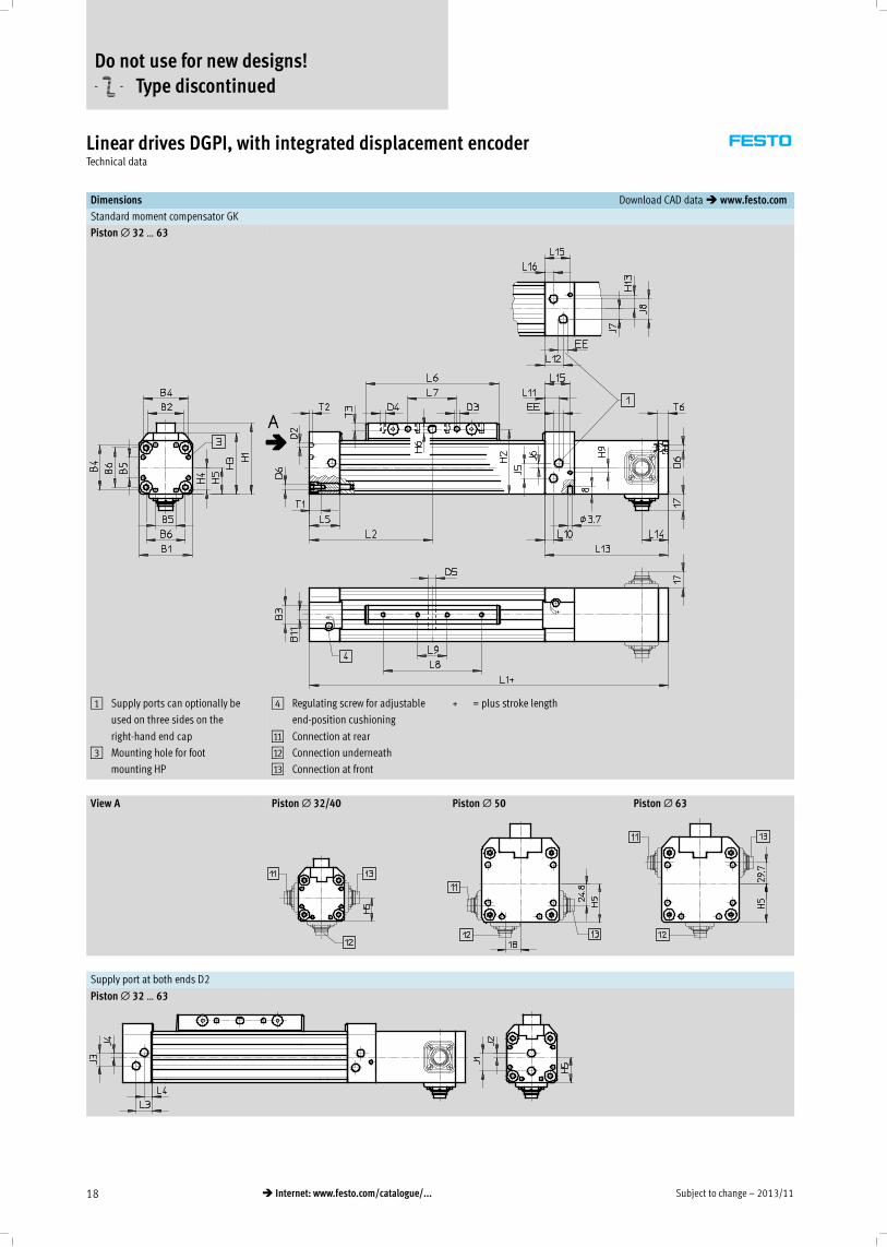
Dimensions Download CAD data� www.festo.com
Standard moment compensator GK
Piston∅ 25
1 Supply ports can optionally be
used on three sides on the
right-hand end cap
3 Mounting hole for foot
mounting HP
4 Regulating screw for adjustable
end-position cushioning
aA Connection at rear
aB Connection underneath
aC Connection at front
+ = plus stroke length
Do not use for new designs!
-U- Type discontinued
2013/11 – Subject to change 17� Internet: www.festo.com/catalogue/...
Linear drives DGPI, with integrated displacement encoderTechnical data
Dimensions Download CAD data� www.festo.com
Supply port at both ends D2
Piston∅ 25
Profile barrel
Do not use for new designs!
-U- Type discontinued
Subject to change – 2013/1118 � Internet: www.festo.com/catalogue/...
Linear drives DGPI, with integrated displacement encoderTechnical data
Dimensions Download CAD data� www.festo.com
Standard moment compensator GK
Piston∅ 32 … 63
1 Supply ports can optionally be
used on three sides on the
right-hand end cap
3 Mounting hole for foot
mounting HP
4 Regulating screw for adjustable
end-position cushioning
aA Connection at rear
aB Connection underneath
aC Connection at front
+ = plus stroke length
View A Piston∅ 32/40 Piston∅ 50 Piston∅ 63
Supply port at both ends D2
Piston∅ 32 … 63
Do not use for new designs!
-U- Type discontinued
2013/11 – Subject to change 19� Internet: www.festo.com/catalogue/...
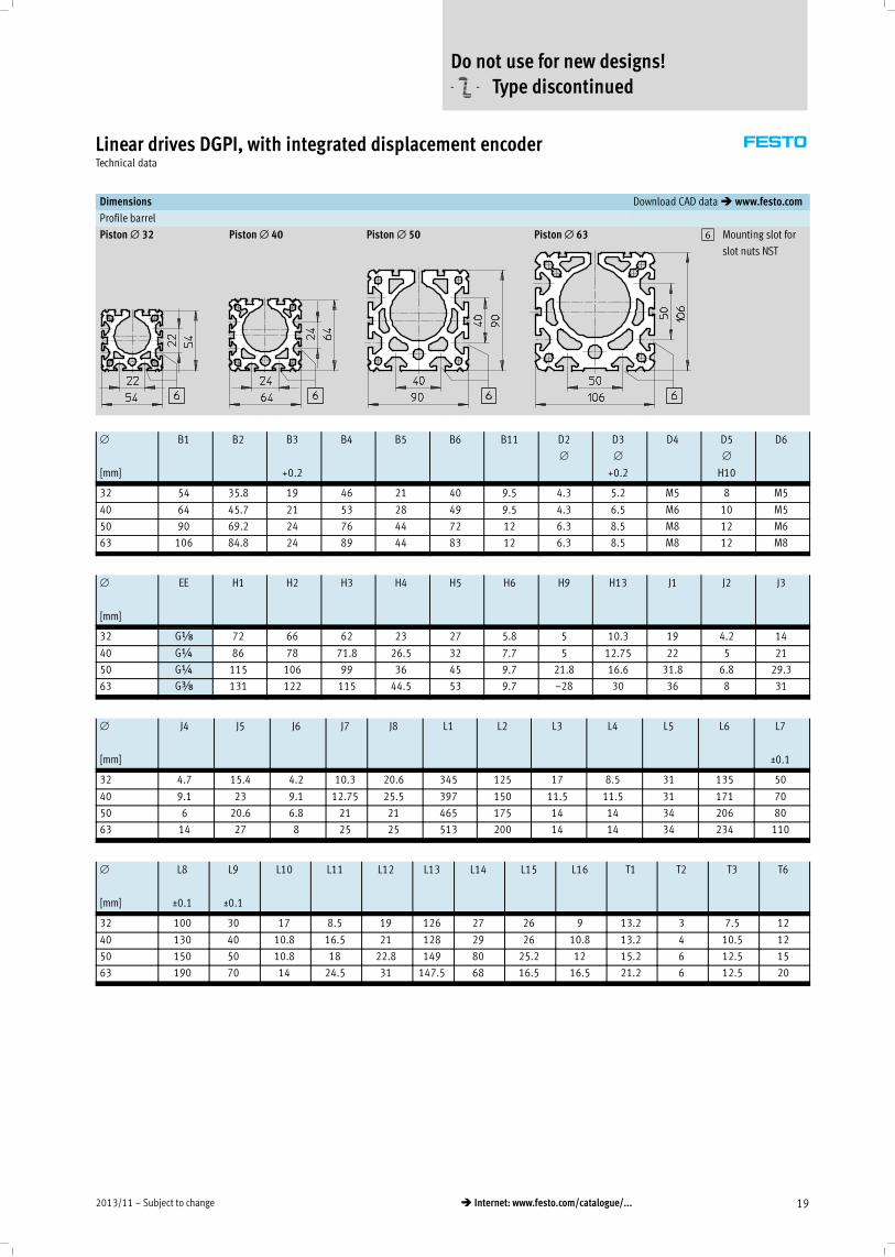
Linear drives DGPI, with integrated displacement encoderTechnical data
Dimensions Download CAD data� www.festo.com
Profile barrel
Piston∅ 32 Piston∅ 40 Piston∅ 50 Piston∅ 63 6 Mounting slot for
slot nuts NST
∅
[mm]
B1 B2 B3
+0.2
B4 B5 B6 B11 D2
∅
D3
∅
+0.2
D4 D5
∅
H10
D6
32 54 35.8 19 46 21 40 9.5 4.3 5.2 M5 8 M5
40 64 45.7 21 53 28 49 9.5 4.3 6.5 M6 10 M5
50 90 69.2 24 76 44 72 12 6.3 8.5 M8 12 M6
63 106 84.8 24 89 44 83 12 6.3 8.5 M8 12 M8
∅
[mm]
EE H1 H2 H3 H4 H5 H6 H9 H13 J1 J2 J3
32 Gx 72 66 62 23 27 5.8 5 10.3 19 4.2 14
40 G¼ 86 78 71.8 26.5 32 7.7 5 12.75 22 5 21
50 G¼ 115 106 99 36 45 9.7 21.8 16.6 31.8 6.8 29.3
63 Gy 131 122 115 44.5 53 9.7 –28 30 36 8 31
∅
[mm]
J4 J5 J6 J7 J8 L1 L2 L3 L4 L5 L6 L7
±0.1
32 4.7 15.4 4.2 10.3 20.6 345 125 17 8.5 31 135 50
40 9.1 23 9.1 12.75 25.5 397 150 11.5 11.5 31 171 70
50 6 20.6 6.8 21 21 465 175 14 14 34 206 80
63 14 27 8 25 25 513 200 14 14 34 234 110
∅
[mm]
L8
±0.1
L9
±0.1
L10 L11 L12 L13 L14 L15 L16 T1 T2 T3 T6
32 100 30 17 8.5 19 126 27 26 9 13.2 3 7.5 12
40 130 40 10.8 16.5 21 128 29 26 10.8 13.2 4 10.5 12
50 150 50 10.8 18 22.8 149 80 25.2 12 15.2 6 12.5 15
63 190 70 14 24.5 31 147.5 68 16.5 16.5 21.2 6 12.5 20
Do not use for new designs!
-U- Type discontinued
Subject to change – 2013/1120 � Internet: www.festo.com/catalogue/...
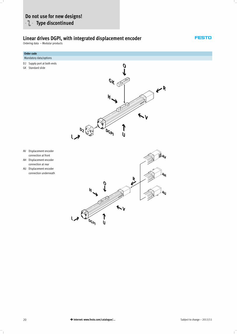
Linear drives DGPI, with integrated displacement encoderOrdering data – Modular products
Order code
Mandatory data/options
D2 Supply port at both ends
GK Standard slide
AV Displacement encoder
connection at front
AH Displacement encoder
connection at rear
AU Displacement encoder
connection underneath
Do not use for new designs!
-U- Type discontinued
2013/11 – Subject to change 21� Internet: www.festo.com/catalogue/...
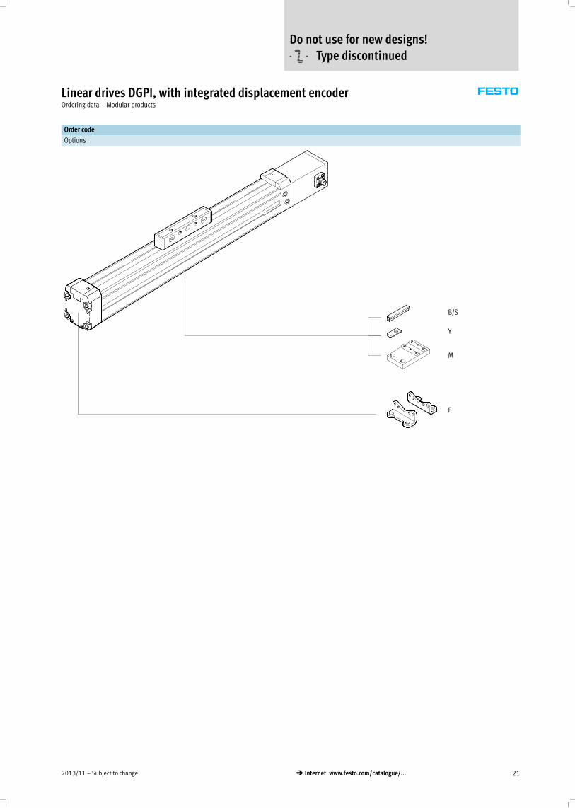
Linear drives DGPI, with integrated displacement encoderOrdering data – Modular products
Order code
Options
B/S
Y
M
F
Do not use for new designs!
-U- Type discontinued
Subject to change – 2013/1122 � Internet: www.festo.com/catalogue/...
Linear drives DGPI, with integrated displacement encoderOrdering data – Modular products
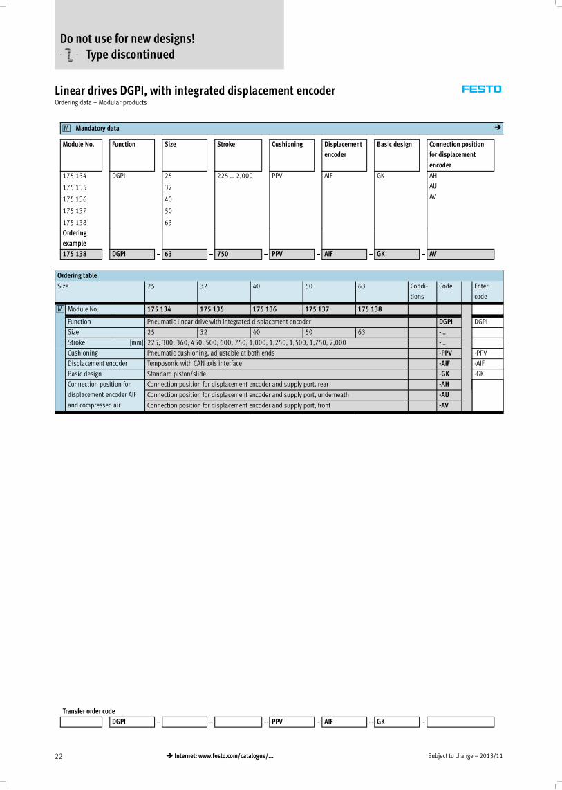
Mandatory data0M �
Module No. Function Size Stroke Cushioning Displacement
encoder
Basic design Connection position
for displacement
encoder
175 134
175 135
175 136
175 137
175 138
DGPI 25
32
40
50
63
225 … 2,000 PPV AIF GK AH
AU
AV
Ordering
example
175 138 DGPI – 63 – 750 – PPV – AIF – GK – AV
Ordering table
Size 25 32 40 50 63 Condi-
tions
Code Enter
code
0M Module No. 175 134 175 135 175 136 175 137 175 138
Function Pneumatic linear drive with integrated displacement encoder DGPI DGPI
Size 25 32 40 50 63 -…
Stroke [mm] 225; 300; 360; 450; 500; 600; 750; 1,000; 1,250; 1,500; 1,750; 2,000 -…
Cushioning Pneumatic cushioning, adjustable at both ends -PPV -PPV
Displacement encoder Temposonic with CAN axis interface -AIF -AIF
Basic design Standard piston/slide -GK -GK
Connection position for
displacement encoder AIF
and compressed air
Connection position for displacement encoder and supply port, rear -AH
Connection position for displacement encoder and supply port, underneath -AU
Connection position for displacement encoder and supply port, front -AV
Transfer order code
DGPI – – – PPV – AIF – GK –
Do not use for new designs!
-U- Type discontinued
2013/11 – Subject to change 23� Internet: www.festo.com/catalogue/...
Linear drives DGPI, with integrated displacement encoderOrdering data – Modular products
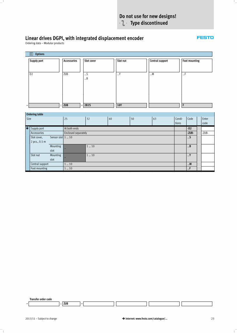
Options0O
Supply port Accessories Slot cover Slot nut Central support Foot mounting
D2 ZUB …S
…B
…Y …M …F
– : ZUB – 2B2S 10Y F
Ordering table
Size 25 32 40 50 63 Condi-
tions
Code Enter
code
� Supply port At both ends -D2
Accessories Enclosed separately :ZUB- :ZUB-
Slot cover,
2 pcs., 0.5 m
Sensor slot 1 … 10 …S
Mounting
slot–
1 … 10 …B
Slot nut Mounting
slot–
1 … 10 …Y
Central support 1 … 10 …M
Foot mounting 1 … 10 …F
Transfer order code
– : ZUB –
Do not use for new designs!
-U- Type discontinued

Subject to change – 2013/1124 � Internet: www.festo.com/catalogue/...
Linear drives DGPIL, with integrated displacement encoderPeripherals overview
1
2
3
4
5
6
7
8
Do not use for new designs!
-U- Type discontinued

2013/11 – Subject to change 25� Internet: www.festo.com/catalogue/...
Linear drives DGPIL, with integrated displacement encoderPeripherals overview
Variants and accessories
Type Brief description � Page/Internet
1 Shock absorber kit
C/E
For avoiding damage at the end stop in the event of malfunction 40
2 Slot nut for slide
X
For mounting loads and attachments on the slide 41
3 Central mounting
Q
For centring loads and attachments on the slide 41
4 Centring sleeves
Z
For centring loads and attachments on the slide 41
5 Slot cover
B/S
For protecting against the ingress of dirt 41
6 Slot nut for mounting slot
Y
For mounting attachments 41
7 Central support
M
For mounting the axis 38
8 Foot mounting
F
For mounting the axis 38
Do not use for new designs!
-U- Type discontinued
Subject to change – 2013/1126 � Internet: www.festo.com/catalogue/...
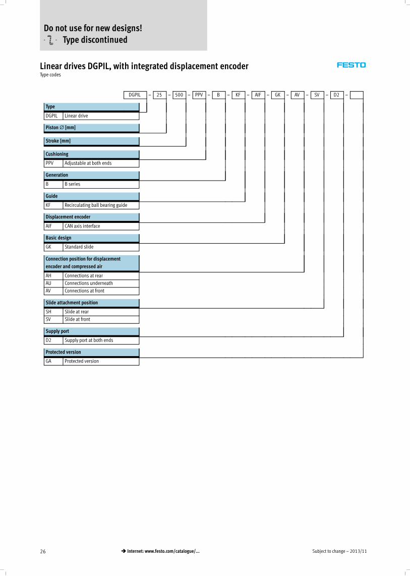
Linear drives DGPIL, with integrated displacement encoderType codes
DGPIL – 25 – 500 – PPV – B – KF – AIF – GK – AV – SV – D2 –
Type
DGPIL Linear drive
Piston∅ [mm]
Stroke [mm]
Cushioning
PPV Adjustable at both ends
Generation
B B series
Guide
KF Recirculating ball bearing guide
Displacement encoder
AIF CAN axis interface
Basic design
GK Standard slide
Connection position for displacement
encoder and compressed air
AH Connections at rear
AU Connections underneath
AV Connections at front
Slide attachment position
SH Slide at rear
SV Slide at front
Supply port
D2 Supply port at both ends
Protected version
GA Protected version
Do not use for new designs!
-U- Type discontinued
2013/11 – Subject to change 27� Internet: www.festo.com/catalogue/...
Linear drives DGPIL, with integrated displacement encoderType codes
� : ZUB – 2S 2X Z F 2C
Accessories
ZUB Accessories enclosed separately
Slot cover
…S Sensor slot
…B Mounting slot
Slot nut
…X For slide
…Y For profile barrel
Centring sleeves
…Z For slide
Central mounting
…Q For slide
Central support
…M Central support
Foot mounting
…F Foot mounting
Shock absorber kit
…C Plus retainer for GK/GV
…E For protected version
Do not use for new designs!
-U- Type discontinued
Subject to change – 2013/1128 � Internet: www.festo.com/catalogue/...
Linear drives DGPIL, with integrated displacement encoderTechnical data
Function
-N- Diameter
25 … 63 mm
-T- Stroke length
225 … 2,000 mm
General technical data
Piston∅ 25 32 40 50 63
Design Piston
Moment compensator
Profile barrel
Mode of operation Double-acting
Operating medium1) Compressed air according to ISO 8573-1:2010 [6:4:4]
Note about the operating/pilot medium Lubricated operation not possible
Pressure dew point 10 °C below ambient temperature/temperature of medium
Cushioning Adjustable at both ends
Cushioning length [mm] 18 20 30
Position sensing Integrated displacement encoder
Measuring principle Digital, magnetostrictive, non-contacting and absolute measurement
Type of mounting Foot mounting
Stroke2)3) [mm] 225; 300; 360; 450; 500; 600; 750; 1,000; 1,250; 1,500; 1,750; 2,000
Protection against rotation/guide Guide rail with slide
Recirculating ball bearing
Protected version4) Optional
Pneumatic connection Gx G¼ Gy
Electrical connection 6-pin round plug to DIN 45322
1) The proportional directional control valve MPYE used requires the characteristic values.
2) Note stroke reduction in combination with SPC200.
3) Supply of compressed air to each end of the cylinder (feature D2) is absolutely essential for Soft Stop SPC11 and axis controller SPC200 as of a length of 500 mm.
4) Protected against particles from above and the side.
Forces [N] and impact energy [Nm]
Piston∅ 25 32 40 50 63
Theoretical force at 6 bar 295 483 754 1,178 1,870
Max. impact energy in the end positions1) 0.1 0.2 0.4 0.8 0.8
1) Cushioning PPV must be completely open for applications with Soft Stop SPC11 and axis controller SPC200.
vperm. =
2 x Eperm.
mdead + mload
�
mload =
2 x Eperm.
v2− mdeadMaximum permissible load:
Permissible impact velocity:vperm. Permissible impact velocity
Eperm. Maximum impact energy
mdead Moving mass (drive)
mload Moving effective load
-H- Note
These specifications represent the
maximum values that can be
achieved. Note the maximum
permissible impact energy.
Do not use for new designs!
-U- Type discontinued
2013/11 – Subject to change 29� Internet: www.festo.com/catalogue/...
Linear drives DGPIL, with integrated displacement encoderTechnical data
Positioning characteristics with axis controller SPC200
Piston∅ 25 32 40 50 63
Repetition accuracy [mm] � 14
Mounting position Any
Minimum load, horizontal1) [kg] 2 3 5 8 12
Maximum load, horizontal1) [kg] 30 45 75 120 180
Minimum load, vertical1) [kg] 2 3 5 8 12
Maximum load, vertical1) [kg] 10 15 25 40 60
Minimum travel speed [m/s] 0.05
Maximum travel speed [m/s] 3
Typical positioning time, long stroke2) [s] 0.75/1.20 0.85/1.20 0.75/1.20 0.95/1.25 0.90/1.20
Typical positioning time, short stroke3) [s] 0.40/0.60 0.45/0.60 0.40/0.60 0.50/0.65 0.50/0.65
Minimum positioning stroke4) [%] 3
Stroke reduction5) [mm] 25 35
Recommended proportional directional control valve � 42
1) Load = effective load + mass of all moving parts on the drive
2) At 6 bar, horizontal mounting position, DGPL-XX-1250, 1,000 mm travel at min./max. load
3) At 6 bar, horizontal mounting position, DNCM-XX-1250, 100 mm travel at min./max. load
4) In relation to the maximum stroke of the drive, but never more than 20 mm
5) The stroke reduction must be maintained on each side of the drive, the max. positionable stroke is therefore: stroke – 2x stroke reduction
Positioning characteristics with end-position controller SPC11
Piston∅ 25 32 40 50 63
Repetition accuracy of a mid-position1) [mm] ±2
Mounting position Any
Minimum load, horizontal2) [kg] 2 3 5 8 12
Maximum load, horizontal2) [kg] 30 45 75 120 180
Minimum load, vertical2) [kg] 2 3 5 8 12
Maximum load, vertical2) [kg] 10 15 25 40 60
Travel time [s] � SoftStop sizing software:� www.festo.com
Recommended proportional directional control valve � 42
1) In the stroke range from 225 … 2,000 mm
2) Load = effective load + mass of all moving parts on the drive
Operating and environmental conditions
Piston∅ 25 32 40 50 63
Operating pressure1) [bar] 4 … 8
Ambient temperature [°C] –10 … +60
Vibration resistance To DIN/IEC 68 Parts 2 – 6, severity level 1
Continuous shock resistance To DIN/IEC 68 Parts 2 – 27, severity level 1
CE marking (see declaration of conformity) To EU EMC Directive
Protection class (displacement encoder) IP65 to IEC 60 529
1) Only applies to applications with Soft Stop SPC11 and axis controller SPC200
Do not use for new designs!
-U- Type discontinued
Subject to change – 2013/1130 � Internet: www.festo.com/catalogue/...
Linear drives DGPIL, with integrated displacement encoderTechnical data
Weight [g]
Piston∅ 25 32 40 50 63
Standard slide GK
Basic weight 2,220 3,320 5,330 10,700 16,870
Additional weight per 10 mm stroke 55 71 99 186 256
Moving load 605 895 1,700 3,000 4,990
Additional weights with protected version GA
Dirt protection cover 1,690 2,500 4,000 – –
Additional weight per 10 mm stroke 26 42 65 – –
Moving load 907 1,350 2,550 – –
Electrical data – Displacement encoder
Power supply [V DC] 24 (–15/+25%)
Maximum current consumption [mA] 90
Resolution [mm] ≤ 0.01
Independent linearity1) Maximum [%] 0.02
Temperature coefficient [ppm/°K] ≤ 15
Interface Digital, CAN with protocol: SPC-AIF
1) Minimum ±50 µm
Materials
Sectional view
1 2 3 4 5
Drive
1 End cap Anodised aluminium
2 Profile Anodised aluminium
3 Cover strip Corrosion-resistant steel
4 Moment compensator Anodised aluminium
5 Displacement encoder housing Anodised aluminium
– Slide Anodised aluminium
– Guide rail Corrosion-resistant steel
– Seals Nitrile rubber, polyurethane
-H- Note
More technical data
� Internet: dpgl
Do not use for new designs!
-U- Type discontinued
2013/11 – Subject to change 31� Internet: www.festo.com/catalogue/...
Linear drives DGPIL, with integrated displacement encoderTechnical data
Characteristic load values
The indicated forces and torques
refer to the centre line of the internal
diameter of the profile barrel.
These values must not be exceeded
during dynamic operation. Special
attention must be paid to the
deceleration phase.
If the drive is simultaneously subjec-
ted to several of the indicated forces
and torques, the following equation
must be satisfied in addition to the
indicated maximum loads:
Fy
Fymax.+
FzFzmax.
+Mx
Mxmax.+
My
Mymax.+
MzMzmax.
≤ 1
Permissible forces and torques
Piston∅ 25 32 40 50 63
Fymax. [N] 3,080 3,080 7,300 7,300 14,050
Fzmax. [N] 3,080 3,080 7,300 7,300 14,050
Mxmax. [Nm] 45 63 170 240 580
Mymax. [Nm] 85 127 330 460 910
Mzmax. [Nm] 85 127 330 460 910
Maximum permissible support span l as a function of force F
The axis may need to be supported
with central supports MUP in order to
limit deflection in the case of large
strokes. The following graphs can be
used to determine the maximum per-
missible support span l as a function
of force F acting on the axis.
Force on the surface of the slide
FF F
Maximum support span l (without central support) as a function of force F
Piston∅ 25 … 40 Piston∅ 50/63
l [mm]
F[N]
I [mm]
F[N]
DGPI...-63
DGPI...-50
Do not use for new designs!
-U- Type discontinued
Subject to change – 2013/1132 � Internet: www.festo.com/catalogue/...
Linear drives DGPIL, with integrated displacement encoderTechnical data
Dimensions Download CAD data� www.festo.com
Standard slide GK
Piston∅ 25
5 Hole for centring sleeve ZBH-9
6 Mounting slot for slot nut NSTL
7 Hole for central mounting SLZZ + = plus stroke length
Basic dimensions
� 16
Protected version GA
Piston∅ 25
+ = plus stroke length
Basic dimensions
� 16
Do not use for new designs!
-U- Type discontinued
2013/11 – Subject to change 33� Internet: www.festo.com/catalogue/...
Linear drives DGPIL, with integrated displacement encoderTechnical data
Dimensions Download CAD data� www.festo.com
Standard slide GK
Piston∅ 32 … 63
5 Hole for centring sleeve ZBH-9
6 Mounting slot for slot nut NSTL
7 Hole for central mounting SLZZ
+ = plus stroke length
Basic dimensions
� 18
Protected version GA
Piston∅ 32/40
+ = plus stroke length
Basic dimensions
� 18
∅
[mm]
B7 B8 B9 B10
±0.03
B12 B14 D1 H1 H7 H8 H10
32 63 79 47 ±0.15 20 112.1 67.6 – 72 77.5 18.5 93.1
40 78.5 96.5 55 ±0.2 20 137.6 79.6 M5 86 90.5 20 106.6
50 97 122 72 ±0.2 40 – – – 115 122.5 26 –
63 121 142 90 ±0.25 40 – – – 131 144.5 30 –
∅
[mm]
H11 H12 H14 L1 L2 L17
+0.2
L18
±0.03
L19
±0.03
L23 L24 L25 T4
max.
T5
32 – 49.5 34.1 345 125 131 40 – 131 – – 12.5 –
40 23.1 54 36.1 397 150 167 40 40 167 150 58 12.5 7
50 – – – 465 175 202 40 40 – – – 18.5 –
63 – – – 513 200 230 40 40 – – – 20.5 –
Do not use for new designs!
-U- Type discontinued
Subject to change – 2013/1134 � Internet: www.festo.com/catalogue/...
Linear drives DGPIL, with integrated displacement encoderOrdering data – Modular products
Order code
Mandatory data
KF Recirculating ball bearing guide
SH Slide at rear
SV Slide at front
D2 Supply port at both ends
GK Standard slide
AV Displacement encoder
connection to front
AH Displacement encoder
connection to rear
AU Displacement encoder
connection underneath
GA Protected version
Do not use for new designs!
-U- Type discontinued
2013/11 – Subject to change 35� Internet: www.festo.com/catalogue/...
Linear drives DGPIL, with integrated displacement encoderOrdering data – Modular products
Order code
Options
B/S
Y
M
F
Z
Q
X
C/E
Do not use for new designs!
-U- Type discontinued

Subject to change – 2013/1136 � Internet: www.festo.com/catalogue/...
Linear drives DGPIL, with integrated displacement encoderOrdering data – Modular products
Mandatory data0M �
Module No. Function Size Stroke Cush-
ioning
Gener-
ation
Guide Displace-
ment
encoder
Basic
design
Connection posi-
tion for displace-
ment encoder
Slide at-
tachment
position
175 134
175 135
175 136
175 137
175 138
DGPIL 25
32
40
50
63
225 …
2,000
PPV B KF AIF GK AH
AU
AV
SH
SV
Ordering
example
175 134 DGPIL – 25 – 450 – PPV – B – KF – AIF – GK – AU – SH –
Ordering table
Size 25 32 40 50 63 Condi-
tions
Code Enter
code
0M Module No. 175 134 175 135 175 136 175 137 175 138
Function Pneumatic linear drive with integrated displacement encoder and slide DGPIL DGPIL
Size 25 32 40 50 63 -…
Stroke [mm] 225; 300; 360; 450; 500; 600; 750; 1,000; 1,250; 1,500; 1,750; 2,000 -…
Cushioning Pneumatic cushioning, adjustable at both ends -PPV -PPV
Generation B series -B -B
Guide Recirculating ball bearing guide -KF -KF
Displacement encoder Temposonic with CAN axis interface -AIF -AIF
Basic design Standard piston/slide -GK -GK
Connection position for
displacement encoder AIF
and compressed air
Connection position for displacement encoder and supply port, rear -AH
Connection position for displacement encoder and supply port, underneath -AU
Connection position for displacement encoder and supply port, front -AV
Slide attachment position Slide at rear -SH
� Slide at front -SV
Transfer order code
DGPIL – – – PPV – B – KF – AIF – GK – –
Do not use for new designs!
-U- Type discontinued
2013/11 – Subject to change 37� Internet: www.festo.com/catalogue/...
Linear drives DGPIL, with integrated displacement encoderOrdering data – Modular products
Options0O
Supply port Protected
version
Acces-
sories
Slot cover Slot nut Centring
sleeve
Central
support
Central
mounting
Foot
mounting
Shock
absorber
D2 GA ZUB …S
…B
…X
…Y
…Z …M …Q …F …C
…E
– D2 – : ZUB – 2S2B 2X F 2C
Ordering table
Size 25 32 40 50 63 Condi-
tions
Code Enter
code
� Supply port At both ends -D2
0O Protected version Protected roller design for harsh
environment– – –
-GA
Accessories Enclosed separately :ZUB- :ZUB-
Slot cover,
2 pcs., 0.5 m
Sensor slot 1 … 10 …S
Mounting
slot–
1 … 10 …B
Slot nut Slide 1 … 10 …X
Mounting
slot–
1 … 10 …Y
Centring sleeve (pack of 10) 10, 20, 30, 40, 50, 60, 70, 80, 90 …Z
Central support 1 … 10 …M
Central mounting 1 … 10 …Q
Foot mounting 1 … 10 …F
Shock
absorber kit
With
retainer,
1-fold
1 … 10 1 …C
1 … 10 – – – 2 …E
1 C Not with protected version GA.
2 E Only with protected version GA.
Transfer order code
– – : ZUB –
Do not use for new designs!
-U- Type discontinued
Subject to change – 2013/1138 � Internet: www.festo.com/catalogue/...
Linear drives DGPL/DGPI/DGPILAccessories
Foot mounting HP
(order code: F)
Material:
Galvanised steel
Free of copper, PTFE and silicone
DGPL-…
DGPI-…/DGPIL-…
+ = plus stroke length
Dimensions and ordering data
For∅ AB AH AO AT AU SA TR Weight Part No. Type
∅ DGPL DGPI(L)
[mm] [g]
25 5.5 29.5 6 3 13 226 327 32.5 61 150 731 HP-25
32 6.6 37 7 4 17 284 379 38 117 150 732 HP-32
40 6.6 46 8.5 5 17.5 335 432 45 188 150 733 HP-40
50 9 61 11 6 25 400 515 65 243 150 734 HP-50
63 11 69 13.5 6 28 456 569 75 305 150 735 HP-63
Central support MUP
(order code: M)
Material:
Galvanised steel
Free of copper, PTFE and silicone
MUP-40
1 Position of the central support
along the profile barrel is freely
selectable.
Please note span.
For piston∅ 25 mm For piston∅ 32 … 63 mm
Dimensions and ordering data
For∅ AH B1 B2 D1 H1 H2 L1 L2 L3 Weight Part No. Type
∅
[mm] [g]
25 29.5 81 58 5.5 13 7 25 – – 33 150 736 MUP-18/25
32 37 35 22 6.6 – – – 41.5 35 89 150 737 MUP-32
40 46 35 22 6.6 – – – 47 40 126 150 738 MUP-40
50 61 50 26 11 – – – 70 58 241 150 739 MUP-50
63 69 50 26 11 – – – 77 65 340 150 800 MUP-63
2013/11 – Subject to change 39� Internet: www.festo.com/catalogue/...
Linear drives DGPL/DGPI/DGPILAccessories
Shock absorber DG-GA
for DGPIL
Protected version GA
(order code: E)
Materials:
Housing: Galvanised steel
Piston rod: High-alloy steel
Seals: NBR, PUR
Free of copper, PTFE and silicone
Ordering data
For∅ Weight Part No. Type
[mm] [g]
25 70 192 875 DG-GA-25-YSR
32 110 192 876 DG-GA-32-YSR
40 140 192 877 DG-GA-40-YSR
Shock absorber YSR-…-C
for DGPL/DGPIL
(order code: C)
Materials:
Housing: Galvanised steel
Piston rod: High-alloy steel
Seals: NBR, PUR
Free of copper, PTFE and silicone
-H- Note
Shock absorber YSRW with
progressive characteristics
� Internet: ysrw
Ordering data
For∅ Weight Part No. Type
[mm] [g]
25 70 34 572 YSR-12-12-C
32 70 34 572 YSR-12-12-C
40 140 34 573 YSR-16-20-C
50 140 34 573 YSR-16-20-C
63 240 34 574 YSR-20-25-C
Subject to change – 2013/1140 � Internet: www.festo.com/catalogue/...
Linear drives DGPL/DGPI/DGPILAccessories
Shock absorber retainer KYP
for DGPL/DGPIL
(order code: C)
Materials:
Retainer: Aluminium
Sleeve: Corrosion-resistant steel
1 Shock absorber retainer KYP
(if the retainer is in contact with
the front cap, the cap serves as
position retainer, the entire
stroke length can be utilised)
2 Shock absorber YSR-...-C
3 Position retainer
(included in the scope of deliv-
ery) either behind or underneath
the shock absorber retainer KYP
Dimensions and ordering data
For∅ B8 D1 D5 H2 H4 Weight Part No. Type
[mm] [g]
25 19 M16x1 M5 69.5 6 95 158 908 KYP-25
32 25 M16x1 M5 80 8 130 158 909 KYP-32
40 32 M22x1.5 M5 102 8 209 158 910 KYP-40
50 35 M22x1.5 M8 124 10 415 158 911 KYP-50
63 44 M26x1.5 M10 152.5 11.5 609 158 912 KYP-63
Ordering data – Push-in fittings Technical data� Internet: quick star
For∅ Comment Part No. Type PU1)
[mm]
25, 32 For connecting compressed air tubing with standard
O.D.
186 098 QS-Gx-8 10
40, 50 186 099 QS-G¼-8
186 101 QS-G¼-10 10
63 186 100 QS-Gy-8 10
186 102 QS-Gy-10
186 103 QS-Gy-12
1) Packaging unit
2013/11 – Subject to change 41� Internet: www.festo.com/catalogue/...
Linear drives DGPL/DGPI/DGPILAccessories
Ordering data Technical data� Internet: mounting component
For∅ Comment Order code Part No. Type PU1)
[mm]
Slot nut NST
25 For mounting slot Y 526 091 NST-HMV-M4 1
32, 40 150 914 NST-5-M5 1
50, 63 150 915 NST-8-M6 1
Slot nut NSTL
25 For slide X 158 410 NSTL-25 1
32 158 411 NSTL-32 1
40 158 412 NSTL-40 1
50 158 413 NSTL-50 1
63 158 414 NSTL-63 1
Centring sleeve ZBH
25 … 63 For slide Z 150 927 ZBH-9 10
Central mounting SLZZ
25 For slide Q 150 900 SLZZ-16/10 1
32, 40 150 901 SLZZ-25/16
50, 63 150 904 SLZZ-50/40 1
Slot cover ABP
32, 40 For mounting slot
Every 0.5 m
B 151 681 ABP-5 2
50, 63 151 682 ABP-8
Slot cover ABP-S
25 … 63 For sensor slot
Every 0.5 m
S 563 360 ABP-5-S1 2
1) Packaging unit
Subject to change – 2013/1142 � Internet: www.festo.com/catalogue/...
Linear drives DGPL/DGPI/DGPILAccessories
Ordering data – Proportional directional control valves Technical data� Internet: mpye
Selection aid
Application For∅ Stroke [mm]
[mm] 225 300 360 450 500 600 750 1,000 1,250 1,500 1,750 2,000
Horizontal/vertical For applications with axis controller SPC200
25 1/1 1/1 1/1 1/1 1/1 1/1 1/1 2/2 2/2 2/2 2/2 2/2
32 1/1 1/1 2/2 2/2 2/2 2/2 2/2 2/2 2/2 2/2 2/2 2/2
40 1/1 2/2 2/2 2/2 2/2 2/2 2/2 3/3 3/3 3/3 3/3 3/3
50 2/2 2/2 2/2 2/2 2/2 3/3 3/3 3/3 3/3 3/3 3/3 3/3
63 3/3 3/3 3/3 3/3 3/3 3/3 3/3 3/3 4/4 4/4 4/4 4/4
For applications with Soft Stop end-position controller SPC11
25 1/1) 1/1 2/1 2/1 2/1 2/2 2/2 2/3 2/3 2/3 2/3 2/3
32 1/1) 2/1 2/1 2/1 2/1 2/1 3/2 3/3 3/3 3/3 3/3 3/3
40 2/1 2/1 2/1 2/1 2/2 3/3 3/4 3/4 3/4 3/4 3/4 3/4
50 1/1 2/1 2/2 3/2 3/3 4/3 4/4 4/4 4/4 4/4 4/4 4/4
63 2/1 2/2 3/3 3/3 4/4 4/4 4/4 4/4 4/4 4/4 4/4 4/4
Valve Selection number Part No. Type
1 151 692 MPYE-5-x-LF-010-B
2 151 693 MPYE-5-x-HF-010-B
3 151 694 MPYE-5-¼-010-B
4 151 695 MPYE-5-y-010-B
1) On request
-H- Note
The representation e.g. 2/1 in the columns means:
Selection number 2
for horizontal application
151 693 MPYE-5-x-HF-010-B
Selection number 1
for vertical application
151 692 MPYE-5-x-LF-010-B
2013/11 – Subject to change 43� Internet: www.festo.com/catalogue/...
Linear drives DGPL/DGPI/DGPILAccessories
Ordering data – Proximity sensor for T-slot, magnetic reed Technical data� Internet: sme
Type of mounting Switching
output
Electrical connection Cable length Part No. Type
[m]
N/O contact
Insertable in the slot lengthwise, flush
with the cylinder profile
Contacting Cable, 3-wire 2.5 150 855 SME-8-K-LED-24
Plug M8x1, 3-pin 0.3 150 857 SME-8-S-LED-24
N/C contact
Insertable in the slot lengthwise, flush
with the cylinder profile
Contacting Cable, 3-wire 7.5 160 251 SME-8-O-K-LED-24
Ordering data – Proximity sensor for T-slot, magneto-resistive Technical data� Internet: smt
Type of mounting Switching
output
Electrical connection Cable length Part No. Type
[m]
N/O contact
Insertable in the slot from above,
flush with the cylinder profile,
short design
PNP Cable, 3-wire 2.5 574335 SMT-8M-A-PS-24V-E-2,5-OE
N/C contact
Insertable in the slot from above,
flush with the cylinder profile,
short design
PNP Cable, 3-wire 7.5 574340 SMT-8M-A-PO-24V-E-7,5-OE
Ordering data – Connecting cables Technical data� Internet: nebu
Electrical connection, left Electrical connection, right Cable length Part No. Type
[m]
Straight socket, M8x1, 3-pin Cable, open end, 3-wire 2.5 541 333 NEBU-M8G3-K-2.5-LE3
5 541 334 NEBU-M8G3-K-5-LE3
Angled socket, M8x1, 3-pin Cable, open end, 3-wire 2.5 541 338 NEBU-M8W3-K-2.5-LE3
5 541 341 NEBU-M8W3-K-5-LE3


![From Dvr to See Exploit of IoT Device...lsl.w r7, r7, #8 \x4f\xea\x07\x27 lsr.w r7, r7, #8 \x4f\xea\x17\x27 box\x00 push {r7} x80 xb4 ldr.w r7, [pc, #4] \xdf\xf8\x04\x70 b #6 \x01\xe0](https://img.pdfslide.us/doc/110x75/5f05e63e7e708231d41546e7/from-dvr-to-see-exploit-of-iot-device-lslw-r7-r7-8-x4fxeax07x27-lsrw.jpg)