Embed Size (px)
Citation preview

LINEAR MOTION CATALOG AND DESIGN GUIDE
WWW.HAYDONKERK.COM

Haydon Kerk Motion Solutions is an innovative technology company that offers a global network of people, facilities and services dedicated to engineering and manufacturing the world’s most advanced motion control solutions.
• Systems design• Engineering• Manufacturing• On-site moldmaking• Precision machining
Providing the technical experience, products, and custom solutions to challenging motion control problems
• Finishing• Assembly• Wiring• Testing• World-wide technical assistance
A standard selection of products is now available 24 hours a day atwww.HaydonKerkExpress.com
A virtual 2D/3D simulation of your customized options available at www.HaydonKerk.com
We can custom-design and manufacture practical motion control solutions to make your operations more productive and efficient.Custom Hybrid and Can-Stack stepper motors and programmable drives
Custom lead-screw and nut assemblies Custom motorized and non-motorized linear rails, slides and assemblies
®

The lead-screw product line offers an extensive array of non-ball lead-screws, anti-backlash nuts, and free-wheeling nuts for use as components in a motion system. Haydon Kerk Motion Solutions offers precision lead-screws and nuts that easily interface to many types of rotary power sources including stepper motors, servos, brushless DC, brush-type DC, and AC synchronous motors. Lead-screws and nuts are also versatile components in systems requiring combination mechanics such as “belt, pulley, lead-screw” systems, and “folded-over” linear actuator designs.
Lead-screws (charts on pages 19 to 23) Nominal screw diameter: 2 mm to 24 mm (5/64-in to 15/16-in) Leads (travel/revolution): 0.3 mm to 76 mm (0.012-in to 3-in)/revolution
Nut Styles (product summary and charts on pages 24 to 26) 8 designs of anti-backlash and freewheeling nuts as a function of load and maximum allowable drag torque.
ScrewRails® & Spline Shafts (product summary and charts on pages 45 to 54) Kerk® ScrewRail® combines both functions in a single, coaxial component. The design saves as much as 80% of the space used by a two-rail system. Kerk Spline Shafts provide anti-rotation for one axis motion or a drive mechanism with rotation for two axes of motion.
Precision Linear Motion ProductsCatalog and Design Guide
How to Use This GuideHaydon Kerk Motion Solutions, Inc. specializes in customized designs to solve complex engineering problems requiring precision linear motion.
Before using this guide, take a few minutes to review the table of contents and scan through the entire catalog. Our catalog is divided into several families illustrating linear motion products that can be used for different levels of assemblies depending on your unique application needs.
The linear rails and slides product line should be considered when a more extensive linear motion solution is desired to minimize overall system material cost, engineering time, and assembly cost. The linear rails and slides are complete mechanical systems that can be powered and motorized to include a linear bearing, rotary bearings, mechanical frame, precision screw and nut, and an electronic drive unit. We can also design, engineer and manufacture a multiple-axis configuration specific to your application requirements.
Typical Configurations (Section begins on page 221) •Traveldistances(strokelengths)upto90-in(229cm) •Motorizedornon-motorized •Optionalmotormountingbracketandslotsforsensors •Patentedanti-backlashnutsorfreewheelingnutsavailable
SECTION 3 – MOTORIZED & NON-MOTORIZED LINEAR RAILS AND SLIDES
The stepper linear actuator product line offers an effective solution that simplifies the conventional way of translating rotary into linear motion. The rotary-to-linear conversion is unique; it takes place within the motor itself therefore eliminating the use of belts and pulleys, rack and pinion and other mechanical components. There’s a detailed tutorial at the beginning of Section 2 that explains the technology.
There are 2 sub-families of stepper motor actuators (Product Summary on page 56)
Hybrid Linear Actuators (Overview on page 75) Footprint: 21 mm to 87 mm (0.8-in to 3.4-in) square Force Output: 2 N to 2200 N (0.5 lb to 500 lb) Linear Travel/step: 1.5 to 127 microns/step (0.00006-in to 0.005-in)/step
Can-Stack Linear Actuators (Overview on page 130) Footprint: 15 mm to 46 mm (0.59-in to 1.8-in) diameter Force Output: 7 N to 260 N (1.6 lb to 58 lb) Linear Travel/step: 20 to 400 microns/step (0.0008-in to 0.016-in)/step
SECTION 2 – STEPPER MOTOR LINEAR ACTUATORS
SECTION 1– LEAD-SCREW AND NUT ASSEMBLIES
1

Contact Information
Haydon Kerk Motion Solutions, Inc. © All rights reserved. This catalog was produced for exclusive use by customers of Haydon Kerk Motion Solutions, Inc, a division of AMETEK, Inc. No part of this book or tech-nical information can be used, reproduced or altered in any form without approval or proper authorization from Haydon Kerk Motion Solu-tions, Inc., AMETEK, Inc., and its global affili-ates. This catalog is intended to be a guide for products and services offered by Haydon Kerk Motion Solutions, Inc. Despite taking all precautions to avoid technical or typographical errors within the catalog some errors may exist. Because most of our products involve a high degree of accuracy and precision we strongly recommend that you contact a Haydon Kerk Motion Solutions technical advisor for more details and specific application requirements. JAN 2016
North American HQ/Operations
Haydon Kerk Motion Solutions, Inc.Haydon Products Division1500 Meriden RoadWaterbury, CT 06705 USATelephone: + 1 203 756 [email protected]
Haydon Kerk Motion Solutions, Inc.Kerk Products Division59 Meadowbrook DriveMilford, NH 03055 USATelephone: + 1 603 213 [email protected]
Asia Operations
Haydon Linear Motors Co., Ltd.Xianlong Industrial ParkNo. 110, Lane 4, Xinyuan RoadNew District, Changzhou, China 213031Telephone: + 86 519 85113316 / 85113312Sales: + 86 519 85123096 / [email protected]
India Operations
AMETEK Instruments India Pvt. Ltd.Haydon Kerk and Pittman Motor Sales148 Prestige Featherlite Tech ParkEPIP Phase II, WhitefieldBangalore - 560 066, India+ 91 080 67823237 (Telephone)+ 91 9686679509 (Mobile)www.HaydonKerk.comwww.Pittman-Motors.comdinesh.dhananjayan@ametek.com
Europe Operations
Haydon Kerk Motion Solutions / France57 rue des Vignerons44220 Coueron - FranceTelephone: + 33 2 40 92 87 [email protected]
Haydon Kerk Motion Solutions / GermanySchmiedstr. 291207 Lauf a.d. Pegnitz - GermanyTelephone: + 49 9123 96 282 [email protected]
Haydon Kerk Motion Solutions, Inc.www.HaydonKerk.com
Contact Information
2

209
209
211
212
213
214
217
218
219
186
186
187
188
190
193
194
199
203
204
206
207
207
Table of ContentsHaydon Kerk Motion Solutions, Inc. • www.HaydonKerk.com • Phone: 800 243 2715 • International: 203 756 7441
IDEA Programmable Drive
Features
Part Number Construction
• PCM4806E / PCM4826E
• ACM4806E / ACM4826E
• DCM4826X
• PBL4850E for Brushless Motors
DCM8027 & DCM8054 Micro-Stepping Drives
DCS4020 Bipolar Chopper Drive
44103 Whisper Drive
Stepper Motor Drives
Product Overview
Part Number Construction
Wiring/Stepping Sequence
Z20000 Rotary Series (Ø 20 mm)
26000 Rotary Series (Ø 26 mm)
Z26000 Rotary Series (Ø 26 mm)
36000 Rotary Series (Ø 36 mm)
46000 Rotary Series (Ø 46 mm)
80000 Pancake Rotary (Ø 80 mm)
Planetary Gear Train Pancake Rotary
AC Synchronous Hybrid Actuators
AC Synchronous Can-Stack Actuators
AC Synchronous Rotary Actuators
Can-Stack Rotary Actuators
Low Profile Pancake Motors andAC Synchronous Linear Actuators
6
SECTION 3: MOTORIZED & NON-MOTORIZED LINEAR RAILS AND SLIDES
Overview
Part Number Construction
Selector Chart
Size 11 Motorized BGS™
Size 17 Motorized BGS™ includes IDEA™ Drive
Size 23 Motorized BGS™
Motorized BGS™ Linear Rails
Product Overview
Linear Rail Application Checklist
221
222
225
225
226
227
228
230
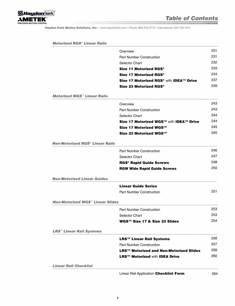
Table of ContentsHaydon Kerk Motion Solutions, Inc. • www.haydonkerk.com • Phone: 800 243 2715 • International: 203 756 7441
7
Overview
Part Number Construction
Selector Chart
Size 11 Motorized RGS®
Size 17 Motorized RGS®
Size 17 Motorized RGS® with IDEA™ Drive
Size 23 Motorized RGS®
Overview
Part Number Construction
Selector Chart
Size 17 Motorized WGS™ with IDEA™ Drive
Size 17 Motorized WGS™
Size 23 Motorized WGS™
Part Number Construction
Selector Chart
RGS® Rapid Guide Screws
RGW Wide Rapid Guide Screws
Linear Guide Series
Part Number Construction
Part Number Construction
Selector Chart
WGS™ Size 17 & Size 23 Slides
LRS™ Linear Rail Systems
Part Number Construction
LRS™ Motorized and Non-Motorized Slides
LRS™ Motorized with IDEA Drive
LRS™ Linear Rail Systems
Non-Motorized RGS® Linear Rails
Motorized RGS® Linear Rails
Non-Motorized Linear Guides
Linear Rail Checklist
Linear Rail Application Checklist Form 264
Motorized WGS™ Linear Rails
Non-Motorized WGS™ Linear Slides
231
231
232
233
234
237
239
243
243
244
244
245
245
246
247
248
250
251
253
253
254
256
257
258
260

8
Who We Are
Whether an application requires a standard item, custom design, new product, or a more sophisticated complete assembly, Haydon Kerk Motion Solutions experienced engineering team will assist you.
We take pride in ourexpertise in customizing products for specificapplication needs.
Haydon Kerk Motion Solutions, Inc. • www.HaydonKerk.com • Phone: 800 243 2715 • International: 203 756 7441
Recognized as a leader in motor miniaturiza-tion, Haydon™ Products Division has been building electric motors and stepper motor based linear actuators for almost half a century. The company’s manufacturing facility, located on ten acres in the heart of Connecticut, supports today’s most efficient technology and manufacturing methods and is ISO 9001 certified. Kerk® Products Division was established in 1976 and has grown to be one of the world’s largest exclusive manu-facturers of non-ball lead screws, linear rails, and actuator systems. Our internationally acclaimed anti-backlash designs and materials provide high accuracy, unsurpassed repeatability, and long life in a full range of motion control applications.
Haydon Kerk Motion Solutions is headquartered in Waterbury, CT, with additional manufacturing operations in Milford, NH, and Changzhou, China. Haydon Kerk also has facilities in Germany and a technical center in Coueron, France.
Haydon Kerk Motion Solutions linear motion products are used in much of today’s sophisticated medical equipment, laboratory instrumentation, machinery automation, aerospace, analytical equipment, computer peripherals, semiconductor industries, and other applications that require precision motion.
AMETEK® is a global leader in electronic instruments and electromechanical devices with colleagues at numerous manufacturing, sales and service locations in the US and in many other countries around the world.
AMETEK consists of 2 operating groups: Electronic Instruments and Electromechanical.
Electronic Instruments is a leader in advanced instruments for the process, aerospace, power, and industrial markets.
Electromechanical is a differentiated supplier of electrical interconnects, specialty metals, and technical motors and associated systems, as well as a leader in floor care and specialty motors.

Motorized and Non-motorized BGS,TM RGS ,® WGS,TM and LRS TM Linear Rails and Linear Slides

221
Motorized and Non-Motorized Linear Rails
Haydon Kerk Motion Solutions, Inc. • www.HaydonKerk.com • Phone: 800 243 2715 • International: 203 756 7441
WGS Motorized with IDEA Drive
The motorized and non-motorized linear rails combine many technologies into a single integrated, linear motion control system. Haydon Kerk Motion Solutions linear rails feature standard wear-compensating, anti-backlash driven carriages to insure repeat-able and accurate positioning. All moving surfaces include engineered polymers that provide a strong, stable platform for a variety of linear motion applications. When integrated with an IDEA Drive, the system combines Haydon hybrid linear actuator technology with a fully programmable, integrated stepper motor drive. By combining technologies into a single preasssembled unit, Haydon Kerk Motion Solutions is able to improve system integration for the equipment OEM or end user. The overall cost for the customer is also lowered by offering a complete solution as it eliminates the need for rotary-to-linear conversion, as well as simplifies product development with fewer components required.
BGS™ products are designed to position heavy loads and maintain repeatability and accuracy while withstanding significant cantilevered loading. A Black Ice® TFE coated lead-screw drives a precision nut embedded in a machined aluminum carriage mounted to a stainless-steel ball rail. The result is a smooth operating, yet rigid linear motion system. Maximum stroke lengths: BGS04 – 18 in. (460 mm); BGS06 – 24 in. (610 mm); BGS08 – 30 in. (760 mm).
The RGS® Linear Rail is a screw driven rail system that offers exceptional linear speed, torsional stiffness and stability, accurate positioning, and long life in a compact, value-priced assembly. The integral mounting base allows support over the entire length if desired. The length and speed of the RGS is not limited by critical screw speed, allowing high RPM and linear speeds, even over long spans. Lengths up to 8 feet (2.4 meters) can readily be built, and longer lengths are possible on a special order basis. RGS linear rails come standard with a wear-compensating, anti-backlash driven carriage. Additional driven or passive car-riages can be added, along with application specific customization. Linear guides, without the drive screw, are also available.
WGS™ Linear Rails feature a more compact profile and improved torsional stiffness and stability. Made of the same quality com-ponents used in the RGS® series. The integral mounting base can provide support over the entire length that can extend up to 8 feet (2.4 meters). Longer lengths are possible on a special order basis. The WGS utilizes sliding plane bearings on a low-profile aluminum guide rail that keeps the motion smooth throughout the travel distance. The lead-screw is precision made of high-quality stainless steel rolled on-site at a Haydon Kerk manufacturing facility.
LRS™ Linear Rail Systems use a precision lead screw assembly mechanism to provide controlled positioning along the axis of a robust aluminum linear slide. The carriage is a small platform with sliding element linear bearings that glide within this specially configured extrusion. The lead screw used in the system is provided with various leads and shaft end configurations that accom-modate virtually any source of rotary power.
When integrated with Haydon Kerk Stepper Motors and electronic drives the various linear rail systems offer virtually limitless linear motion control possibilities – from high-efficiency industrial automation systems to extremely precise analytical and diagnostic equipment systems used by the medical industry.
More importantly, every Haydon Kerk linear rail product is supported by an experienced technical team recognized for innovation, customization, and dedicated customer service.
Motorized and Non-Motorized Linear Rails from Haydon Kerk Motion Solutions...Integrated technologies that provide
high precision and accuracy in motion control
BGS Motorized with IDEA Drive
WGS Non-Motorized
RGS Motorized with IDEA Drive
LRS Motorized with IDEA Drive
RGS Non-Motorized
LIN
EA
R R
AIL
TE
CH
NO
LO
GY

222
Haydon Kerk Motion Solutions, Inc. • www.HaydonKerk.com • Phone: 800 243 2715 • International: 203 756 7441
Information needed to properly size a linear rail system
Linear Rail Application Checklist
Haydon Kerk™ Linear Rail Systems are designed to be precision motion devices. Many variables must be considered before applying a particular rail system in an application. The following is a basic checklist of information needed that will make it easier for the Haydon Kerk engineering team to assist you in choosing the proper linear rail. See order form on last page of this catalog.
Linear Rail Application Checklist
1) o Maximum Load? _______________ (N or lbs.)
3) o Rail Mount Orientation? The force needed to move the load is dependent on the orientation of the load relative to the force of gravity. For example, total required force in the horizontal plane (D) is a function of friction and the force needed for load acceleration (Ff + Fa). Total force in the vertical plane is a function of friction, load acceleration, and gravity (Ff + Fa + Fg).
2) o Load Center of Gravity (cg) Distance and Height (mm or inches)? See illustrations (A) (B) (C) below.
(A)
(B)
(C)
Dimensions (o mm / o inch): o (A) _______ ... OR... o (B) ______ AND... o (C) ________
Orientation: o (D) o (E) ______° o (F) o (G) o (H) ______°
LIN
EA
R R
AIL
TE
CH
NO
LO
GY
CH
EC
KL
IST

Haydon Kerk Motion Solutions, Inc. • www.haydonkerk.com • Phone: 800 243 2715 • International: 203 756 7441
Linear Rail Application Checklist
223
Linear Rail Application Checklist (Continued)
5) o Move Profile?A trapezoidal move profile divided into 3 equal segments (J) is a common move profile and easy to work with. Another common move profile is a triangular profile divided into 2 equal segments (K).
If using a trapezoidal (J) or triangular (K) move profile, the following is needed…
a) o Point to point move distance __________ (mm or inches)
b) o Move time __________ (seconds) including time of acceleration and deceleration
c) o Dwell time between moves __________ (seconds)
The trapezoidal move profile (J) is a good starting point in helping to size a system for prototype work.
A complex move profile (L) requires more information.
a) o Time (in seconds) including: T1, T2, T3, T4, T5…Tn and Tdwell
b) o Acceleration / Deceleration (mm/sec.2 or inches/sec.2) including: A1, A2, A3…An
For more information call Haydon Kerk Motion Solutions Engineering at 203 756 7441.
4) o Stroke Length to Move Load? _______________ (mm or inches)Overall rail size will be a function of stroke length needed to move the load, the rail frame size (load capa-bility), the motor size, and whether or not an integrated stepper motor programmable drive system is added.
(J)
(K)
(L)
LIN
EA
R R
AIL
TE
CH
NO
LO
GY
CH
EC
KL
IST

224
Haydon Kerk Motion Solutions, Inc. • www.HaydonKerk.com • Phone: 800 243 2715 • International: 203 756 7441
Linear Rail Application Checklist
Linear Rail Application Checklist (Continued)
8) o Positioning Resolution Required? __________ (mm/step or inches/step)Positioning resolution is the smallest move command that the system can generate. The resolution is a function of many factors including the drive electronics, lead screw pitch, and encoder (if required). The terms “resolution” and “accuracy” should never be used interchangeably.
9) o Closed-Loop Position Correction Required? o YES o NO In stepper motor-based linear rail systems, position correction is typically accomplished using a rotary incremental encoder (either optical or magnetic).
11) o Operating Temperature Range _____________ (°C or °F) a) o Will the system operate in an environment in which the worst case temperature is above room temperature? b) o Will the system be mounted in an enclosure with other equipment generating heat?
12) o Controller / Drive Information? a) o Haydon Kerk IDEA™ Drive (with Size 17 Stepper Motors only) b) o Customer Supplied Drive... Type? o Chopper Drive o L / R Drive Model / Style of Drive: ____________________________________________________________
14)* o Step Resolution? a) o Full Step b) o Half-Step c) o Micro-Step
13) o Power Supply Voltage? _______________ (VDC)
15)* o Drive Current? _____________ (Arms / Phase) and _____________ (Apeak / Phase)
16)* o Current Boost Capability? _________ (%)
... or ...
... or ...
6) o Position Accuracy Required? __________ (mm or inches)Accuracy is defined as the difference between the theoretical position and actual position capability of the system. Due to manufacturing tolerances in components, actual travel will be slightly different than theo-retical “commanded” position. See figure (M) below.
7) o Position Repeatability Required? __________ (mm or inches)Repeatability is defined as the range of positions attained when the rail is commanded to approach the same position multiple times under identical conditions. See figure (M) below.
(M)
10) o Life Requirement? (select the most important application parameter) a) o Total mm or inches _________ b) o Number of Full Strokes _________ c) o Number of Cycles _________
* If the Haydon Kerk IDEA™ Drive is used disregard items 14, 15, and 16.
LIN
EA
R R
AIL
TE
CH
NO
LO
GY
CH
EC
KL
IST

225
Haydon Kerk Motion Solutions, Inc. • www.HaydonKerk.com • Phone: 800 243 2715 • International: 203 756 7441
BGSTM Linear Rails with Recirculating Ball Slide
The BGS™ Linear Rail combines many technolo-gies into a single integrated linear motion platform. The system provides excellent load capability and is engineered for both normal and overhanging loads. High roll, pitch, and yaw moment loading capability allows the system to maintain tight accuracy and repeatability, even in applications requiring significant cantilevered loading.
At the heart of the BGS Linear Rail system is a Haydon™ hybrid linear actuator with a precision 303 stainless steel lead-screw. The lead screw drives a machined aluminum carriage mounted to a precision stainless steel ball slide resulting in a rigid, smooth-operating motion system. The screw is coated with Black Ice® TFE coating providing a permanent wear-resistant dry lubrication.
When integrated with an IDEA™ Drive, the system combines Size 17 Haydon hybrid linear actuator technology with a fully pro-grammable, integrated stepper motor drive. By combining technologies into a single preasssembled unit, Haydon Kerk Motion Solutions is able to improve system integration for the equipment OEM or end user. The overall cost for the customer is also low-ered by offering a complete solution as it eliminates the need for rotary-to-linear conversion, and simplified product development.
Motorized BGS™ Linear Rails
Identifying the part number codes when ordering Motorized BGS
EXAMPLE:
BGS06B-M0100-XXX = BGS™ for 135 lb (600 N) load, lead-screw with Black Ice® TFE coating, motorized with Size 17 stepper motor, 0.1-in (2.54 mm) lead-screw lead with no added features. Order number must include dashes ( – ) in sequence as shown above.
For assistance or order entry, call the Haydon Kerk Motion Solutions Engineering at 203 756 7441. Customized systems available. Visit www.HaydonKerk.com for recent updates.
BG
Prefix:BG = Ball GuideSystem
FrameStyle
S = Standard
S B
Coating
B = Black Ice®
TFE wear resist, dry lubricant
0100
Nominal Thread Lead Code
Code numbersin Motor-ized BGS ProductSelector Chart
UniqueIdentifier
Proprietary suffix as-signed to a specific customer application. The identi-fier can ap-ply to either a standard or custom part.
XXX–
Carriage holes available in Metric sizes
M3M4M5M6
M
Drive/Mounting
M = MotorizedG = IDEA integrated programmable drive - USB communicationsJ = IDEA integrated programmable drive - RS485 communications
– Drives available with size 17 motors only.
Frame Size:Load*
04 = 22 lbs (100 N) 06 = 135 lbs (600 N)08 = 225 lbs (1,000 N)
06
* Maximum static load
See page 222 “Linear Rail Ap-plication Checklist” or Checklist Form on page 264.
–
MO
TO
RIZ
ED
BG
S™
LIN
EA
R R
AIL
S

Motorized BGS™ Linear Rails
Haydon Kerk Motion Solutions, Inc. • www.haydonkerk.com • Phone: 800 243 2715 • International: 203 756 7441
226
Motorized BGS™ Product Selector Chart
002500390050006300790098010001180125015701970200025003150375039404000472050006300750098410001200
0.0250.0390.0500.06250.0790.0980.1000.1180.1250.1570.1970.2000.2500.3150.3750.3940.4000.4720.5000.6300.7500.9841.0001.200
0.6351.001.271.592.002.502.543.003.184.005.005.086.358.009.5310.0010.1612.0012.7016.0019.0525.0025.4030.48
LeadCode
NominalThreadLead
inches mm
BGS04 BGS06 BGS08Size 11 Double StackSize 17 Single Stack*
Hybrid LinearActuator Motor...
Size 17 Single Stack*Size 17 Double Stack*
Size 23 Single Stack*Size 23 Double Stack*
Max. Stroke Length
Max. Load (Horizontal)**
Roll Moment
Pitch Moment
Yaw Moment
18-in (460 mm)
22 lbs (100 N)
5.72 lbs-ft (7.75 Nm)
4.88 lbs-ft (6.60 Nm)
5.68 lbs-ft (7.70 Nm)
24-in (610 mm)
135 lbs (600N)
11.62 lbs-ft (15.75 Nm)
7.93 lbs-ft (10.75 Nm)
9.15 lbs-ft (12.40 Nm)
30-in (760 mm)
225 lbs (1,000 N)
22.50 lbs-ft (30.5 Nm)
19.36 lbs-ft (26.25 Nm)
22.27 lbs-ft (30.20 Nm)
BGS04 BGS06 BGS08•••••••
••
•
•••
•••
••••••••••••
••
••
••
•* Size 17 Single and Double Stack Hybrid Linear Actuator Stepper Motors (BGS06) are available with an optional programmable IDEA™ Drive. Integrated IDEA™ Drives are not available with BGS04 or BGS08 style linear rails.
** For vertical load information see the www.HaydonKerk.com website or the HaydonKerk products catalog forSize 11, Size 17, and Size 23 Linear Actuator specifications.
MO
TO
RIZ
ED
BG
S™
LIN
EA
R R
AIL
S

227
Haydon Kerk Motion Solutions, Inc. • www.HaydonKerk.com • Phone: 800 243 2715 • International: 203 756 7441
For Size 11 Hybrid Linear Actuator Stepper Motor motor technical specifications, see page 88.
Dimensional Drawing: Motorized BGS04 with Size 11 Double Stack Hybrid Stepper Motor
BGS04 with Size 11 Double Stack Linear Actuator Stepper Motor
A(1.40)33.56
B(1.0)25.40
C(0.50)12.70
D(0.75)19.05
E(0.69)17.53
F(0.60)15.24
G(1.00)25.40
H(0.75)19.05
I J(1.22)30.86
K(0.87)22.10
L(0.75)19.05
Z1(0.11)
2.8
Z2(0.20)
5.1
Z3(0.09)
2.3(inch)mm
* Dimension “I” is a function of required travel distance.
**
BGS04 is recommended for horizontal loads up to 22 lbs (100 N).
Motorized BGS™ Linear Rails
4 x M2x0.4
Dimensions = (inches) mm
MO
TO
RIZ
ED
BG
S™
LIN
EA
R R
AIL
S

Motorized BGS™ Linear Rails
228
Haydon Kerk Motion Solutions, Inc. • www.haydonkerk.com • Phone: 800 243 2715 • International: 203 756 7441
Technical specifications for the Size 17 Single Stack Hybrid Linear Actuator Stepper Motor are provided on page 100.
BGS04 with Size 17 motor is available with the Haydon Kerk IDEA™ integrated programmable drive. For IDEA Drive technical specifications, see pages 109 and 209.
Dimensional Drawing: Motorized BGS04 with Size 17 Hybrid Stepper Motor
BGS04 with Size 17 Linear Actuator Stepper Motors
A(1.40)33.56
B(1.0)25.40
C(0.50)12.70
D(0.75)19.05
E(0.69)17.53
F(0.60)15.24
G(1.00)25.40
H(0.75)19.05
I J(1.22)30.86
K(0.87)22.10
L(0.75)19.05
Z1(0.11)
2.8
Z2(0.20)
5.1
Z3(0.09)
2.3(inch)mm
BGS04 is recommended for horizontal loads up to 22 lbs (100 N).
* Dimension “I” is a function of required travel distance.
**
Dimensional Drawing: Motorized BGS04 with Size 17 Hybrid Motor with IDEA™ Drive
4 x M2x0.4
4 x M2x0.4
Dimensions = (inches) mm
MO
TO
RIZ
ED
BG
S™
LIN
EA
R R
AIL
S

229
Haydon Kerk Motion Solutions, Inc. • www.HaydonKerk.com • Phone: 800 243 2715 • International: 203 756 7441
Technical specifications for Size 17 Hybrid Linear Actuator Stepper Motors single stack are on page 100; for double stack see page 106.
BGS06 with Size 17 is available with the Haydon Kerk IDEA™ integrated programmable drive. For technical specifications, see pages 109 and 209.
Dimensional Drawing: Motorized BGS06 with Size 17 Hybrid Motors
BGS06 with Size 17 Linear Actuator Stepper Motor
A(2.00)50.80
B(1.50)38.10
C(0.75)19.05
D(1.13)28.58
E(0.81)20.57
F(0.90)22.86
G(1.50)38.10
H(1.25)31.75
I J(1.50)38.15
K(1.05)26.77
L(1.13)28.58
Z1(0.14)
3.6
Z2(0.25)
6.4
Z3(0.13)
3.3(inch)mm
* Dimension “I” is a function of required travel distance.
**
BGS06 is recommended for horizontal loads up to 135 lbs (600 N).
Dimensional Drawing: Motorized BGS06 with Size 17 Hybrid Motor with IDEA™ Drive
Motorized BGS™ Linear Rails
4 x M3x0.5
4 x M3x0.5
Dimensions = (inches) mm
Dimensions = (inches) mm
MO
TO
RIZ
ED
BG
S™
LIN
EA
R R
AIL
S

Motorized BGS™ Linear Rails
230
Haydon Kerk Motion Solutions, Inc. • www.haydonkerk.com • Phone: 800 243 2715 • International: 203 756 7441
Technical specifications for Size 23 Hybrid Linear Actuator Stepper Motors single stack are on page 111; for double stack see page 116.
Dimensional Drawing: Motorized BGS08 with Size 23 Hybrid Motors
BGS08 with Size 23 Linear Actuator Stepper Motor
A(2.70)68.58
B(1.75)44.45
C(1.00)25.40
D(1.60)40.64
E(0.98)24.89
F(1.25)31.75
G(1.50)38.10
H(1.25)31.75
I J(1.79)45.39
K(1.29)32.69
L(1.60)40.64
Z1(0.20)
5.1
Z2(0.33)
8.4
Z3(0.19)
4.8(inch)mm
* Dimension “I” is a function of required travel distance.
**
BGS08 is recommended for horizontal loads up to 225 lbs (1,000 N).
4 x M4x0.7 or4 x M5x0.8
Dimensions = (inches) mm
MO
TO
RIZ
ED
BG
S™
LIN
EA
R R
AIL
S

231
Haydon Kerk Motion Solutions, Inc. • www.HaydonKerk.com • Phone: 800 243 2715 • International: 203 756 7441
Motorized RGS® Rapid Guide Screw Linear Rails
The Motorized RGS® Rapid Guide Screw is a screw-driven rail that offers exceptional linear speed, accurate positioning, and long life in a compact, value-priced assembly. The length and speed of the RGS is not limited by critical screw speed, allowing high RPM and linear speeds, even over long spans. Lengths up to 8 feet (2.4 meters) can readily be built, and longer lengths are possible on a special order basis.
This system combines many Haydon Kerk Motion Solutions patented motion technologies into a single integrated, linear motion control system. The Motorized RGS linear rails feature standard wear-compensating, anti-backlash driven carriages to insure repeatable and accurate positioning. All moving surfaces include Kerkite® engineered polymers running on Kerkote® TFE coating, providing a strong, stable platform for a variety of linear motion applications. When integrated with an IDEA Drive, the system combines Haydon™ hybrid linear actuator technology with a fully programmable, integrated stepper motor drive. By combining technologies into a single preassembled unit, Haydon Kerk Motion Solutions is able to improve system integration for the equipment OEM or end user. The overall cost for the customer is also lowered by of-fering a complete solution as it eliminates the need for rotary-to-linear conversion, as well as simplifies product development with fewer components required.
Motorized RGW06 with Size 17 Double Stack linear actuator stepper motor.
Motorized RGW06 with Size 17 Double Stack and IDEA Drive.
Motorized RGS04 with Size 17 Double Stack stepper motor.
Motorized RGS® Linear Rails
Identifying the part number codes when ordering Motorized RGS
EXAMPLE:
RGW06K-M0100-XXX = RGS®, Wide frame style for sensor mounting, for 35 lb (156 N) load, lead-screw with Kerkote® TFE coating, motorized with Size 17 stepper motor, 0.1-in (2.54 mm) lead-screw lead with no added features. Order number must include dashes ( – ) in sequence as shown above.
For assistance or order entry, call the Haydon Kerk Motion Solutions Engineering at 603 213 6290. Customized systems available. Visit www.HaydonKerk.com for recent updates.
RG
Prefix:RG = Rapid Guide Screw
FrameStyle
S = StandardW = Widesensor mount capability
W K
Coating
K = Kerkote®
X = Special (ex: Kerkote with grease)
M
Drive/Mounting
M = MotorizedG = IDEA integrated programmable drive - USB communicationsJ = IDEA integrated programmable drive - RS485 communications
– Drives available with size 17 motors only.
0100
Nominal Thread Lead Code
Code numbersin Motor-ized RGS ProductSelector Chart(Page 232)
UniqueIdentifier
Proprietary suffix as-signed to a specific customer application. The identi-fier can ap-ply to either a standard or custom part.
XXX––
Carriage holes available in Metric sizes
M3M4M5M6** Maximum static load
06
Frame Size:Load**
04* = 15 lbs (67 N) 06 = 35 lbs (156 N)08* = 50 lbs (222 N)10 = 100 lbs (445 N)
* 04 and 08 not available with with wide (W) frame style
See page 222 “Linear Rail Ap-plication Checklist” or Checklist Form on page 264.
MO
TO
RIZ
ED
RG
S®
LIN
EA
R R
AIL
S
Motorized RGS® Linear Rails
232
Motorized RGS Product Selector Chart
0025
0039
0050
0063
0079
0098
0100
0118
0125
0157
0197
0200
0250
0315
0375
0394
0400
0472
0500
0630
0750
0984
1000
1200
1500
2000
0.025
0.039
0.050
0.0625
0.079
0.098
0.100
0.118
0.125
0.157
0.197
0.200
0.250
0.315
0.375
0.394
0.400
0.472
0.500
0.630
0.750
0.984
1.000
1.200
1.500
2.000
0.635
1.00
1.27
1.59
2.00
2.50
2.54
3.00
3.18
4.00
5.00
5.08
6.35
8.00
9.53
10.00
10.16
12.00
12.70
16.00
19.05
25.00
25.40
30.48
38.10
50.80
l
l
l
l
l
l
l
l
l
l
l
l
l
l
l
l
l
l
l
l
l
l
l
l
l
l
l
l
l
l
l
l
l
l
l
l
l
l
l
l
l
l
l
l
l
l
l
l
l
l
l
l
l
l
l
l
l
l
l
l
l
l
l
l
l
l
l
l
l
RGS04Size 11DSSize 17SSSize 17DS
RGS06
Size 17SSSize 17DSSize 23SSSize 23DS
RGW06
Size 17SSSize 17DSSize 23SSSize 23DS
RGS08
Size 23SSSize 23DS
RGS10
Size 23SSSize 23DS
RGW10
Size 23SSSize 23DS
LeadCode
NominalThread Leadinches mm
Please consult factory for other available leads
The RGS and RGW style numbers 04, 06, 08 and 10 indicate the recommended load capacity of the system.
SS = Single Stack, standard Hybrid Linear Actuator Stepper Motor
DS = Double Stack Hybrid Linear Actuator Stepper Motor
RGW = wide base with parallel guide tracks for traversing sensor mount devices
For motor specifications: Size 11 DS, see page 88; Size 17 SS, see page 100; Size 17 DS, see page 106;Size 23 SS, see page 111; Size 23 DS, see page 116.
Haydon Kerk Motion Solutions, Inc. • www.haydonkerk.com • Phone: 800 243 2715 • International: 203 756 7441
MO
TO
RIZ
ED
RG
S®
LIN
EA
R R
AIL
S

233
Haydon Kerk Motion Solutions, Inc. • www.HaydonKerk.com • Phone: 800 243 2715 • International: 203 756 7441
The smallest available screw-driven slide that offers a compact profile, reliable linear speed, accurate positioning, and long life in a high quality assembly.
For Size 11 Double Stack Hybrid Linear Actuator Stepper Motor technical specifi-cations, see page 88.
Dimensional Drawing: Motorized RGS04 with Size 11 Double Stack Hybrid Stepper Motor
Motorized RGS04 with Size 11 Double Stack Linear Actuator Stepper Motor
A(0.4)10.2
D(0.75)19.0
D1(0.75)19.0
E(0.53)13.5
F(1.4)35.6
G(1.0)25.4
H(0.5)12.7
I*4-40UNC
L1(0.5)12.7
N(0.375)
9.52
N1(1.0)25.4
P(0.6)15.2
Q(0.5)12.7
S(0.37)
9.4
T(0.15)
3.8
U(0.23)
5.8
V(0.73)18.5
Z1(0.11)
2.8
Z2(0.2)5.1
Z3(0.09)
2.3(inch)mm
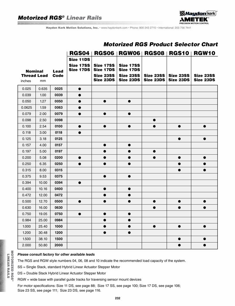
Recommended for horizontal loads up to 67 N (15 lbs).
* Metric threads also available for carriage.
Motorized RGS® Linear Rails
Dimensions = (inches) mm
MO
TO
RIZ
ED
RG
S®
LIN
EA
R R
AIL
S
234
Haydon Kerk Motion Solutions, Inc. • www.haydonkerk.com • Phone: 800 243 2715 • International: 203 756 7441
RGS04 with Size 17 Double Stack Hybrid Linear Stepper Motor
The RGS04 with Size 17 Hybrid Linear Actuator Stepper Motor provides exceptional torsional stiffness and stability.
Size 17 Hybrid Linear Actuator Stepper Motor Single Stack technical specifications are on page 100.
For more performance, see Size 17 Hybrid Double Stack Linear Actuator Stepper Motor technical specifications on page 106.
Motorized RGS04 with Size 17 Linear Actuator Stepper Motor or Size 17 Double Stack
A(0.4)10.2
D(0.75)19.0
D1(0.75)19.0
E(0.53)13.5
F(1.4)35.6
G(1.0)25.4
H(0.5)12.7
I*4-40UNC
L1(0.5)12.7
N(0.375)
9.52
N1(1.0)25.4
P(0.6)15.2
Q(0.5)12.7
S(0.37)
9.4
T(0.15)
3.8
U(0.23)
5.8
V(0.73)18.5
Z1(0.11)
2.8
Z2(0.2)5.1
Z3(0.09)
2.3(inch)mm
Dimensional Drawing: Motorized RGS04 with Size 17 Hybrid Stepper Motor
Recommended for horizontal loads up to 67 N (15 lbs).
* Metric threads also available for carriage.
Motorized RGS® Linear Rails
Dimensions = (inches) mm
MO
TO
RIZ
ED
RG
S®
LIN
EA
R R
AIL
S

235
Haydon Kerk Motion Solutions, Inc. • www.HaydonKerk.com • Phone: 800 243 2715 • International: 203 756 7441
Dimensional Drawing: Motorized RGS06 with Size 17 Hybrid Stepper Motor
Motorized RGS06 with Size 17 Linear Actuator Stepper Motor or Size 17 Double Stack
A(0.6)15.2
D(1.13)28.7
D1(1.13)28.7
E(0.79)20.1
F(2.0)50.8
G(1.5)38.1
H(0.75)19.0
I*6-32UNC
L1(1.0)25.4
N(0.5)12.7
N1(1.5)38.1
P(0.9)22.9
Q(0.74)18.8
S(0.55)13.9
T(0.22)
5.6
U(0.35)
8.9
V(1.1)27.8
Z1(0.14)
3.6
Z2(0.25)
6.3
Z3(0.13)
3.3(inch)mm
The RGS06 with Size 17 Hybrid Linear Actuator Stepper Motor provides a more stable platform for a variety of linear motion applications.
Size 17 Hybrid Linear Actuator Stepper Motor Single Stack technical specifications are on page 100. Size 17 Hybrid Double Stack Linear Actuator Stepper Motor technical specifications on page 106.
Recommended for horizontal loads up to 156 N (35 lbs).
* Metric threads also available for carriage.
Motorized RGS® Linear Rails
Dimensions = (inches) mm
MO
TO
RIZ
ED
RG
S®
LIN
EA
R R
AIL
S

A wide-based Motorized RGW06 with Size 17 Linear Actuator Stepper Motor or Size 17 Double Stack
The RGW06 with Size 17 Hybrid Linear Actuator Stepper Motor provides parallel slots for a flag, sensor bracket or other added components.
Size 17 Hybrid Linear Actuator Stepper Motor technical specifications are on page 100. Size 17 Hybrid Double Stack Linear Actuator Step-per Motor technical specifications on page 106.
236
Haydon Kerk Motion Solutions, Inc. • www.haydonkerk.com • Phone: 800 243 2715 • International: 203 756 7441
A(0.6)15.2
D(2.0)50.8
D1(1.13)28.7
F(2.0)50.8
G(1.5)38.1
H(0.75)19.0
I*6-32UNC
L1(1.0)25.4
N(0.5)12.7
P(1.46)37.1
Q(1.04)26.4
S1(0.83)21.1
T(0.51)13.0
U(0.63)16.0
V(1.39)35.3
Z1(0.14)
3.6
Z2(0.25)
6.3
Z3(0.14)
3.6(inch)mm
Dimensional Drawing: Motorized RGW06 with Size 17 Hybrid Stepper Motor
RGW06 with Size 17 Double Stack Hybrid Linear Stepper Motor
Recommended for horizontal loads up to 156 N (35 lbs).
* Metric threads also available for carriage.
Motorized RGS® Linear Rails
Dimensions = (inches) mm
Recommended Sensor Part Number: Sunx PM-L24
Sensor Mounting Kit
MO
TO
RIZ
ED
RG
S®
LIN
EA
R R
AIL
S

237
Haydon Kerk Motion Solutions, Inc. • www.HaydonKerk.com • Phone: 800 243 2715 • International: 203 756 7441
Dimensional Drawing: Motorized RGS04 with Size 17 Hybrid Stepper Motor and IDEA Drive
Motorized RGS with an integrated IDEA™ programmable drive and Size 17 Linear Actuator Stepper Motor or a higher performance Size 17 Double StackStepper Motor
The Size 17 RGS and RGW Series provides a completely integrated linear motion system with electronically programmed precision in motion control.
Technical Specifications for components:
•Size17HybridLinearActuator: Page100•Size17HybridDoubleStack: Page106•SensorMountingKitforRGW06: Page236•IDEAProgrammableDrive: Page109&209
RGS04 with a Size 17 Hybrid Double Stack Linear Stepper Motor and a programmable IDEA Drive.
A(0.4)10.2
D(0.75)19.0
D1(0.75)19.0
E(0.53)13.5
F(1.4)35.6
G(1.0)25.4
H(0.5)12.7
I*4-40UNC
L1(0.5)12.7
N(0.375)
9.52
N1(1.0)25.4
P(0.6)15.2
Q(0.5)12.7
S(0.37)
9.4
T(0.15)
3.8
U(0.23)
5.8
V(0.73)18.5
Z1(0.11)
2.8
Z2(0.2)5.1
Z3(0.09)
2.3(inch)mm
Recommended for horizontal loads up to 67 N (15 lbs).
* Metric threads also available for carriage.
Motorized RGS® Linear Rails
Dimensions = (inches) mm
MO
TO
RIZ
ED
RG
S®
LIN
EA
R R
AIL
S

Haydon Kerk Motion Solutions, Inc. • www.haydonkerk.com • Phone: 800 243 2715 • International: 203 756 7441
Dimensional Drawing: Motorized RGS06 with Size 17 Hybrid Stepper Motor and IDEA Drive
A(0.6)15.2
D(1.13)28.7
D1(1.13)28.7
E(0.79)20.1
F(2.0)50.8
G(1.5)38.1
H(0.75)19.0
I*6-32UNC
L1(1.0)25.4
N(0.5)12.7
N1(1.5)38.1
P(0.9)22.9
Q(0.74)18.8
S(0.55)13.9
T(0.22)
5.6
U(0.35)
8.9
V(1.1)27.9
Z1(0.14)
3.6
Z2(0.25)
6.3
Z3(0.13)
3.3(inch)mm
Recommended for horizontal loads up to 156 N (35 lbs).
Dimensional Drawing: Motorized RGW06 Wide base with Size 17 Hybrid and IDEA Drive
A(0.6)15.2
D(2.0)50.8
D1(1.13)28.7
F(2.0)50.8
G(1.5)38.1
H(0.75)19.0
I*6-32UNC
L1(1.0)25.4
N(0.5)12.7
P(1.46)37.1
Q(1.04)26.4
S1(0.83)21.1
T(0.51)13.0
U(0.63)16.0
V(1.39)35.3
Z1(0.14)
3.6
Z2(0.25)
6.3
Z3(0.14)
3.6(inch)mm
Recommended for horizontal loads up to 156 N (35 lbs).
* Metric threads also available for carriage.
* Metric threads also available for carriage.
238
Motorized RGS® Linear Rails
Dimensions = (inches) mm
Dimensions = (inches) mm
MO
TO
RIZ
ED
RG
S®
LIN
EA
R R
AIL
S

RGW06 with Size 23 Double Stack Hybrid Linear Stepper Motor
239
Haydon Kerk Motion Solutions, Inc. • www.HaydonKerk.com • Phone: 800 243 2715 • International: 203 756 7441
Dimensional Drawing: Motorized RGS06 with Size 23 Hybrid Stepper Motor
Motorized RGS and RGW with Size 23 Linear Actuator Stepper Motor or Size 23 Double Stack
A(0.6)15.2
D(1.13)28.7
D1(1.13)28.7
E(0.79)20.1
F(2.0)50.8
G(1.5)38.1
H(0.75)19.0
I*6-32UNC
L1(1.0)25.4
N(0.5)12.7
N1(1.5)38.1
P(0.9)22.9
Q(0.74)18.8
S(0.55)13.9
T(0.22)
5.6
U(0.35)
8.9
V(1.1)27.9
Z1(0.14)
3.6
Z2(0.25)
6.3
Z3(0.13)
3.3(inch)mm
Powering this RGS and wide platform RGW system is the Size 23 Hybrid Linear Actuator Stepper Motor which offers a variety of resolutions per step (down to 0.0079 mm [0.0003125-in]). These high performance motion control systems provide stability and precison for a variety of linear motion applications.
Technical Specifications for components:
•Size23HybridLinearActuator: Page111•Size23HybridDoubleStack: Page116•SensorMountingKitforRGW06: Page236
[1.581] 40.15Single Stack(2.130] 54.1
Double Stack
Recommended for horizontal loads up to 156 N (35 lbs).
* Metric threads also available for carriage.
Motorized RGS® Linear Rails
Dimensions = (inches) mm
MO
TO
RIZ
ED
RG
S®
LIN
EA
R R
AIL
S

240
Haydon Kerk Motion Solutions, Inc. • www.haydonkerk.com • Phone: 800 243 2715 • International: 203 756 7441
A(0.6)15.2
D(2.0)50.8
D1(1.13)28.7
F(2.0)50.8
G(1.5)38.1
H(0.75)19.0
I*6-32UNC
L1(1.0)25.4
N(0.5)12.7
P(1.46)37.1
Q(1.04)26.4
S1(0.83)21.1
T(0.51)13.0
U(0.63)16.0
V(1.39)35.3
Z1(0.14)
3.6
Z2(0.25)
6.3
Z3(0.14)
3.6(inch)mm
Dimensional Drawing: Motorized RGW06 with Size 23 Hybrid Stepper Motor
Dimensional Drawing: Motorized RGS08 with Size 23 Hybrid Stepper Motor
A(0.8)20.3
D(1.6)40.6
D1(1.6)40.6
E(1.06)26.9
F(2.7)68.6
G(1.75)44.5
H(1.0)25.4
I*10-24UNC
L1(1.0)25.4
N(0.625)
15.9
N1(1.5)38.1
P(1.25)15.9
Q(1.0)25.4
S(0.74)18.8
T(0.3)7.6
U(0.51)12.9
V(1.47)37.3
Z1(0.2)5.1
Z2(0.33)
8.4
Z3(0.19)
4.8(inch)mm
Recommended for horizontal loads up to 222 N (50 lbs).
Motorized RGS08 for heavier weight applications
Recommended for horizontal loads up to 156 N (35 lbs).
* Metric threads also available for carriage.
* Metric threads also available for carriage.
Motorized RGS® Linear Rails
Dimensions = (inches) mm
Dimensions = (inches) mm
MO
TO
RIZ
ED
RG
S®
LIN
EA
R R
AIL
S
241
Haydon Kerk Motion Solutions, Inc. • www.HaydonKerk.com • Phone: 800 243 2715 • International: 203 756 7441
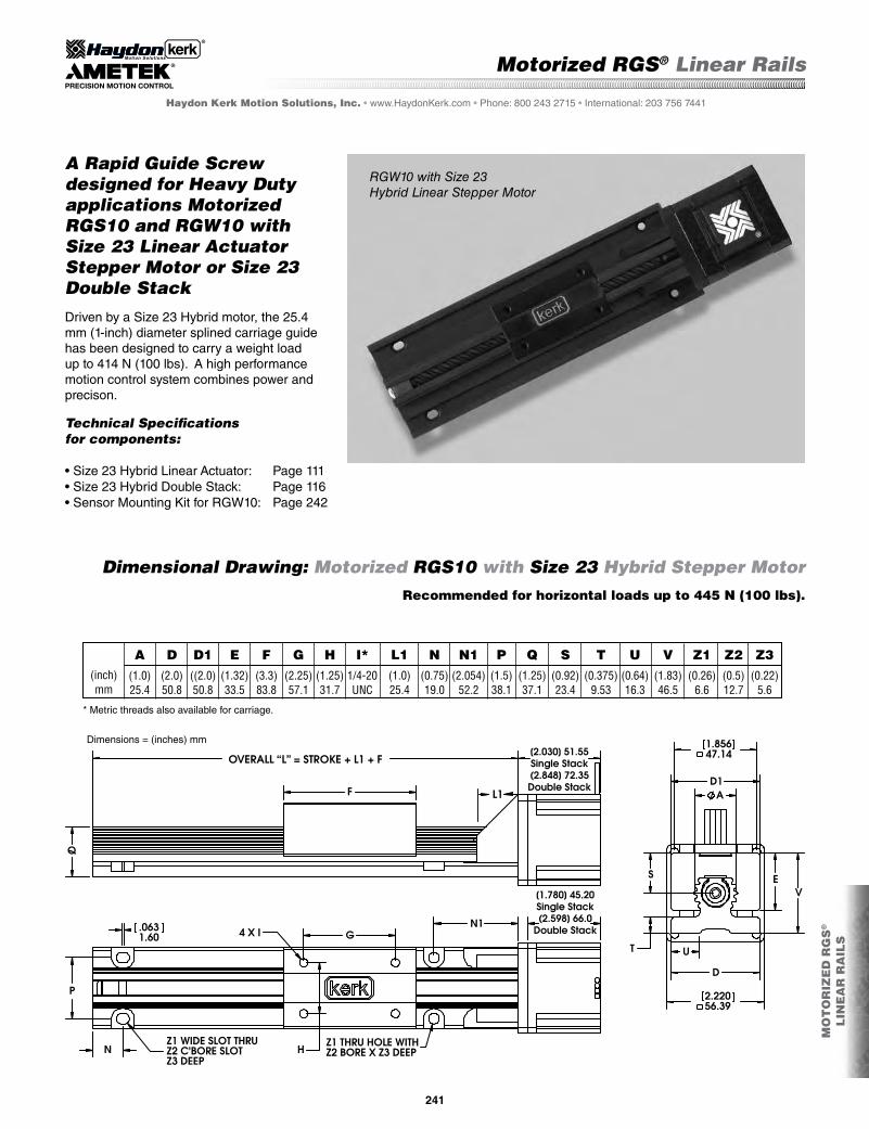
Dimensional Drawing: Motorized RGS10 with Size 23 Hybrid Stepper Motor
A Rapid Guide Screw designed for Heavy Duty applications Motorized RGS10 and RGW10 with Size 23 Linear Actuator Stepper Motor or Size 23 Double Stack
A(1.0)25.4
D(2.0)50.8
D1((2.0)50.8
E(1.32)33.5
F(3.3)83.8
G(2.25)57.1
H(1.25)31.7
I*1/4-20UNC
L1(1.0)25.4
N(0.75)19.0
N1(2.054)
52.2
P(1.5)38.1
Q(1.25)37.1
S(0.92)23.4
T(0.375)
9.53
U(0.64)16.3
V(1.83)46.5
Z1(0.26)
6.6
Z2(0.5)12.7
Z3(0.22)
5.6(inch)mm
Driven by a Size 23 Hybrid motor, the 25.4 mm (1-inch) diameter splined carriage guide has been designed to carry a weight load up to 414 N (100 lbs). A high performance motion control system combines power and precison.
Technical Specifications for components:
•Size23HybridLinearActuator: Page111•Size23HybridDoubleStack: Page116•SensorMountingKitforRGW10: Page242
Recommended for horizontal loads up to 445 N (100 lbs).
RGW10 with Size 23Hybrid Linear Stepper Motor
* Metric threads also available for carriage.
Motorized RGS® Linear Rails
Dimensions = (inches) mm
MO
TO
RIZ
ED
RG
S®
LIN
EA
R R
AIL
S

242
Haydon Kerk Motion Solutions, Inc. • www.haydonkerk.com • Phone: 800 243 2715 • International: 203 756 7441
A(1.0)25.4
D(3.38)85.9
D1(2.0)50.8
F(3.3)83.8
G(2.25)57.1
H(1.25)31.7
I*1/4-20UNC
L1(1.0)25.4
N(0.75)19.0
P(2.6)66.0
Q(1.56)39.6
S1(1.22)31.0
T(0.69)17.5
U(1.33)33.8
V(2.15)54.6
Z1(0.26)
6.6
Z2(0.4)10.2
Z3(0.43)10.9
(inch)mm
Dimensional Drawing: Motorized RGW10 with Size 23 Hybrid Stepper Motor
Recommended for horizontal loads up to 445 N (100 lbs).
* Metric threads also available for carriage.
Motorized RGS® Linear Rails
Dimensions = (inches) mm
Recommended Sensor Part Number: Sunx PM-L24Sensor Mounting Kit
MO
TO
RIZ
ED
RG
S®
LIN
EA
R R
AIL
S

Motorized Wide Guide Screw Linear Slides
Identifying the part number codes when ordering Wide Guide Screw Slides
FrameStyle
S = Standard
WG S 06 K M
Prefix:WG
= Wide Guide Screw
Coating
K = Kerkote®
X = Special (ex: Kerkote with grease)
Drive/Mounting
M = Motorized
G = IDEA Programmable Drive, Size 17 only
0100
Nominal Thread Lead Code (inches)
Code numbersin Part NumberSelector Chart
–
UniqueIdentifier
Proprietary suffix as-signed to a specific customer application. The identifier can apply to either a standard or custom part.
XXX––
Frame Size:Load**
06 = 35 lbs (156 N)
Carriage holes available in Metric sizes:
M3M4M5M6
With Haydon Kerk Motion Solutions, Inc. wide range of available leads, speeds of more than 60 inches per second (1.5 meters per second) are possible, rivaling belts and cables while offering superior positioning accuracy, repeatability and axial stiffness.
The WGS utilized sliding plane bearings on a low profile aluminum guide rail that keeps the motion smooth throughout the travel distance. The lead-screw is precision-made of high-quality stainless steel rolled on-site at our U.S. manufacturing facility. All mov-ing surfaces include Kerkite® high performance polymers running on Kerkote® TFE coating.
This system combines many Haydon Kerk Motion Solutions patented motion technologies into a single integrated, linear motion control system. The Motorized WGS linear rails feature standard wear-compensating, anti-backlash driven carriages to insure repeatable and accurate positioning. When integrated with an IDEA™ Drive, the system combines Haydon™ hybrid linear actuator technology with a fully programmable, integrated stepper motor drive. By combining technologies into a single preassembled unit, Haydon Kerk Motion Solutions is able to improve system integration for the equipment OEM or end user.
The slides come with a wear-compensating, anti-backlash driven carriage. Additional driven or passive carriages can be added, along with application specific customization. Linear guides, without the drive screw, are also available.
Made of the same quality components used in the RGS® series, the Kerk® Motorized WGS Linear Slide utilizes a screw-driven carriage that offers reli-able, continuous linear speed while maintaining ac-curate positioning. The length and speed of the WGS is not limited by critical screw speed, allowing high RPM, linear speed and long stroke lengths. The WGS slide has a unique, compact profile that provides improved torsional stiffness and stability over RGS and RGW products. The integral mounting base can provide sup-port over the entire length that can extend up to 8 feet (2.4 meters). Longer lengths are possible on a special order basis.
Standard leads include .100-in, .200-in, .500-in and 1.00-in (2.54, 5.08, 12.7 and 25.4 mm) travel per revolu-tion. Many optional leads, both inch and metric based, offer everything from high efficiency to non-backdriving leads for vertical applications, eliminating the need for brakes.
WGS 06 with Size 17 [43 mm] hybrid linear stepper motor and IDEA Drive
243
Motorized WGS™ Linear Rails
MO
TO
RIZ
ED
WG
S™
LIN
EA
R R
AIL
SHaydon Kerk Motion Solutions, Inc. • www.haydonkerk.com • Phone: 800 243 2715 • International: 203 756 7441

Motorized WGS06 Selector Chart
244
Dimensions = inch [ mm ]
inch(mm)Inch Lead
Thread Lead Code
0.050(1.27)
0.079(2.00)
0.157(4.00)
0.197(5.00)
0.250(6.35)
0.375(9.53)
0.400(10.16)
0.472(12.00)
0.750(19.05)
0.984(25.00)
1.200(30.48)
0050 0079 0157 0197 0250 0375 0400 0472 0750 0984 1200
0.100(2.54)
0100
0.200(5.08)
0200
0.500(12.70)
0500
1.000(25.40)
1000
For motor specifications: Size 17 Single Stack, see page 100; Size 17 Double Stack, see page 106; Size 23 Single Stack see page 111; Size 23 Double Stack see page 116.
L
FILE NAME: WGS06K-G43-CATALOG
T
G E
OVERALL RAIL LENGTH = STROKE + D + F + G
F
H
C D
I
SINGLE STACKB
DOUBLE STACK
A
(MM)INCH A B C D E F G H I J K L M N P1 P2 P3 Q R S T U V
-G43SIZE 17
(58.0)2.283MAX.
(63.72)2.509MAX.
(77.67)3.058MAX.
(24.9).98
(27.9)1.1
(63.5)2.50
(11.2).44
(9.7).38
(6.4).250
(50.8)2.00
(25.4)1.000
(19.1).75
(38.1)1.50
(25.4)1.000
(3.81).150
(6.60).260
(6.50).256
(53.95)2.124
(41.25)1.624
(50.8)2.00
(23.3).92
(2.3).090
(42.0)1.66
* METRIC THREADS ALSO AVAILABLE
R
K
TYP. P2 P32X
M
.250 Q 4X 8-32 UNC - 2B*
N
P3 P2 P1 THRU
P1 THRU
UTYP.
S
V
J
ADDITIONAL MOUNTING HOLES RECOMMENDED EVERY 10 inches (254mm) FROM DRIVE END. CONTACT HAYDON KERK FOR EXACT LOCATIONS OR CUSTOM LOCATIONS.
WGS06 is recommended for horizontal loads up to 35 lbs (156 N).
Dimensional Drawing: Motorized WGS06 with Size 17 Hybrid Motor with IDEA™ Drive
Motorized with Size 17 and Size 23 Single and Double Stack Hybrid Linear Actuator Stepper Motors
Motorized WGS™ Linear Rails
Haydon Kerk Motion Solutions, Inc. • www.haydonkerk.com • Phone: 800 243 2715 • International: 203 756 7441
MO
TO
RIZ
ED
WG
S™
LIN
EA
R R
AIL
S

245
L
P2 P3TYP.
J
R
2X
K
M
.250 Q 4X 8-32 UNC - 2B*
N
P1 THRU P3 P2
P1 THRU
UTYP.
S
(MM)INCH
-M43SIZE 17
(42.2)1.660MAX.
(33.8)1.330MAX.
(47.75)1.880MAX.
(24.9).98
(27.9)1.1
(63.5)2.50
(11.2).44
(9.7).38
(6.4).250
(50.8)2.00
(25.4)1.000
(19.1).75
(38.1)1.50
(25.4)1.000
(3.81).150
(6.60).260
(6.50).256
(53.95)2.124
(41.25)1.624
(50.8)2.00
(23.3).92
(2.3).090
* METRIC THREADS ALSO AVAILABLE
FILE NAME: WGS06K-M43-CATALOG
I
A T
C E F
H
G D
SINGLE STACKB
DOUBLE STACK
OVERALL RAIL LENGTH = STROKE + D + F + G
A B C D E F G H I J K L M N P1 P2 P3 Q R S T U
ADDITIONAL MOUNTING HOLES RECOMMENDED EVERY 10 inches (254mm) FROM DRIVE END. CONTACT HAYDON KERK FOR EXACT LOCATIONS OR CUSTOM LOCATIONS.
L
FILE NAME: WGS06K-M57-CATALOG
C E F G
D
T
B OVERALL RAIL LENGTH = STROKE + D + F + G DOUBLE STACK
SINGLE STACK
A
I
H
R
P2
TYP. P3
J K
2X
M
.250 Q 4X 8-32 UNC - 2B*
N
P3 P2 P1 THRU
P1 THRU
UTYP.
S
(MM)INCH
-M57SIZE 23
(56.4)2.220MAX.
(45.2)1.780MAX.
(66)2.598MAX.
(24.9).98
(27.9)1.1
(63.5)2.50
(11.2).44
(16.5).65
(6.4).250
(50.8)2.00
(25.4)1.000
(19.1).75
(38.1)1.50
(25.4)1.000
(3.81).150
(6.60).260
(6.50).256
(53.95)2.124
(41.25)1.624
(56.4) 2.220MAX.
(23.3).92
(2.3).090
* METRIC THREADS ALSO AVAILABLE
ADDITIONAL MOUNTING HOLES RECOMMENDED EVERY 10 inches (254mm) FROM DRIVE END. CONTACT HAYDON KERK FOR EXACT LOCATIONS OR CUSTOM LOCATIONS.
A B C D E F G H I J K L M N P1 P2 P3 Q R S T U
Dimensions = inch [ mm ]
Dimensional Drawing: Motorized WGS06 with Size 17 Hybrid Motor
Dimensions = inch [ mm ]
Dimensional Drawing: Motorized WGS06 with Size 23 Hybrid Motor
MO
TO
RIZ
ED
WG
S™
LIN
EA
R R
AIL
S
Motorized WGS™ Linear Rails
Haydon Kerk Motion Solutions, Inc. • www.haydonkerk.com • Phone: 800 243 2715 • International: 203 756 7441
WGS06 is recommended for horizontal loads up to 35 lbs (156 N).
WGS06 is recommended for horizontal loads up to 35 lbs (156 N).

Non-Motorized RGS® Linear Rails
Identifying the part number codes when ordering Rapid Guide Screw Rails
Kerk® Rapid Guide Screw Linear Rails
Made of the same quality components used in the motorized series, the Kerk® RGS® Rapid Guide Screw is utilizes a screw-driven slide that offers reliable, continuous linear speed while maintaining accurate positioning. The length and speed of the RGS is not limited by critical screw speed, allowing high RPM and linear speeds. The RGS rail has a unique, compact profile that provides exceptional torsional stiffness and stability for its size and weight. The integral mounting base can provide support over the entire length that can extend up to 8 feet (2.4 meters). Longer lengths are possible on a special order basis.
Standard leads include .100-in, .200-in, .500-in and 1.00-in (2.54, 5.08, 12.7 and 25.4 mm) travel per revolution. Many optional leads, both inch and metric based, offer everything from high efficiency to non-backdriving leads for vertical applications, eliminating the need for brakes. With Haydon Kerk Motion Solu-tions, Inc. wide range of available leads, speeds of more than 60 inches per second (1.5 meters per second) are possible, rivaling belts and cables while offering superior positioning accuracy, repeatability and axial stiffness.
The RGS (or the wider platform RGW) includes a splined aluminum guide that keeps the motion smooth throughout the travel distance. The lead-screw is precision-made of high-quality stainless steel rolled on-site at our U.S. manufactuing facility. All moving surfaces include Kerkite® high performance polymers running on Kerkote® TFE coating.
The slides come with a wear-compensating, anti-backlash driven carriage. Ad-ditional driven or passive carriages can be added, along with application spe-cific customization. Linear guides, without the drive screw, are also available.
Haydon Kerk Motion Solutions, Inc. • www.HaydonKerk.com • Phone: 800 243 2715 • International: 203 756 7441
RGS
RGW
LinearGuide
NO
N-M
OT
OR
IZE
D R
GS
® L
INE
AR
RA
ILS
246
EXAMPLE:
RGW10K-B0100-XXX = RGS®, Wide frame style for sensor mounting, for 100 lb (445 N) load, lead-screw with Kerkote® TFE coating, with Size 17 stepper in-line motor mount, 0.1-in (2.54 mm) lead-screw lead with no added features. Order number must include dashes ( – ) in sequence as shown above.
For assistance or order entry, call the Haydon Kerk Motion Solutions Engineering at 603 213 6290. Customized systems available. Visit www.HaydonKerk.com for recent updates.
RG
Prefix:RG = Rapid Guide Screw
FrameStyle
S = StandardW = Widesensor mount capability
W K
Coating
K = Kerkote®
X = Special (ex: Kerkote with grease)
0100
Nominal Thread Lead Code(inches)
Code numbersin Part NumberSelector Chart (page 247)
UniqueIdentifier
Proprietary suffix as-signed to a specific customer applica-tion. The identifier can apply to either a standard or custom part.
– XXX–10
Frame Size:Load**
04* = 15 lbs (67 N) 06 = 35 lbs (156 N)08* = 50 lbs (222 N)10 = 100 lbs (445 N)
Carriage holes available in Metric sizes
M3M4M5M6
See page 222 “Linear Rail Application Checklist” or Checklist Form on page 264.
* 04 and 08 not available with with wide (W) frame style** Maximum static load
B
Drive/Mounting
A = None
B = in-line motor mount

Non-Motorized RGS® Linear Rails
NO
N-M
OT
OR
IZE
D R
GS
®
LIN
EA
R R
AIL
S
247
Haydon Kerk Motion Solutions, Inc. • www.haydonkerk.com • Phone: 800 243 2715 • International: 203 756 7441
3.0(.02)4.0
(.03)5.0
(.04)6.0
(.04)4.0
(.03)5.0
(.04)6.0
(.04)7.0
(.05)5.0
(.04)6.0
(.04)7.0
(.05)8.0
(.06)5.0
(.04)6.5
(.05)7.0
(.05)8.5
(.06)
100,000,000(254,000,000)100,000,000
(254,000,000)100,000,000
(254,000,000)100,000,000
(254,000,000)100,000,000
(254,000,000)100,000,000
(254,000,000)100,000,000
(254,000,000)100,000,000
(254,000,000)100,000,000
(254,000,000)100,000,000
(254,000,000)100,000,000
(254,000,000)100,000,000
(254,000,000)100,000,000
(254,000,000)100,000,000
(254,000,000)100,000,000
(254,000,000)100,000,000
(254,000,000)
1.0(.016)
1.5(.023)
2.5(.039)
4.5(.070)
1.0(.016)
1.5(.023)
2.5(.039)
4.5(.070)
1.1(.018)
1.7(.027)
3.0(.047)
6.0(.096)
1.3(.020)
2.0(.031)
3.0(.047)
6.5(.101)
15(67)15
(67)15
(67)15
(67)35
(156)35
(156)35
(156)35
(156)50
(222)50
(222)50
(222)50
(222)100
(445)100
(445)100
(445)100
(445)
.3 x 10-5
(6.5 x 10⁻⁶).3 x 10-5
(6.5 x 10).3 x 10-5
(6.5 x 10⁻⁶).3 x 10-5
(6.5 x 10⁻⁶)1.5 x 10⁻⁵
(4.2 x 10⁻⁶)1.5 x 10⁻⁵
(4.2 x 10⁻⁶)1.5 x 10⁻⁵
(4.2 x 10⁻⁶)1.5 x 10⁻⁵
(4.2 x 10⁻⁶)5.2 x 10⁻⁵
(20.0 x 10⁻⁶)5.2 x 10⁻⁵
(20.0 x 10⁻⁶)5.2 x 10⁻⁵
(20.0 x 10⁻⁶)5.2 x 10⁻⁵
(20.0 x 10⁻⁶)14.2 x 10⁻⁵
(3.9 x 10⁻⁵)14.2 x 10⁻⁵
(3.9 x 10⁻⁵)14.2 x 10⁻⁵
(3.9 x 10⁻⁵)14.2 x 10⁻⁵
(3.9 x 10⁻⁵)
oz - in(NM)
inch(cm)
oz-in/lb(NM/Kg)
lbs(N)
oz-in sec2/in(KgM2/M)
TypicalDrag
Torque
Life @1/4 Design
Load*
Torque-to-MoveLoad*
DesignLoad*
ScrewInertia
RGS 06
RGS 04
RGS 04
RGS 04
RGS 04
RGS 08
RGS 06
RGS 06
RGS 06
RGS 10
RGS 08
RGS 08
RGS 08
RGS 10
RGS 10
RGS 10
NOTE: RGS® assemblies with lengths over 36-in. (914.4 mm) and/or leads higher than .5-in (12.7 mm) will likely have higher drag torque than listed values.
* Determined with load in a horizontal position
.100(2.54).200
(5.08).500
(12.70)1.000
(25.40).100
(2.54).200
(5.08).500
(12.70)1.000
(25.40).100
(.254).200
(5.08).500
(12.70)1.000
(25.40).100
(2.54).200
(5.08).500
(12.70)1.000
(25.40)
inch(mm)
InchLead
0100
0200
0500
1000
0100
0200
0500
1000
0100
0200
0500
1000
0100
0200
0500
1000
Thread LeadCode
0.4(10.2)
0.4(10.2)
0.4(10.2)
0.4(10.2)
0.6(15.2)
0.6(15.2)
0.6(15.2)
0.6(15.2)
0.8(20.3)
0.8(20.3)
0.8(20.3)
0.8(20.3)
1.0(25.4)
1.0(25.4)
1.0(25.4)
1.0(25.4)
1/4(6.4)1/4
(6.4)1/4
(6.4)1/4
(6.4)3/8
(9.5)3/8
(9.5)3/8
(9.5)3/8
(9.5)1/2
(12.7)1/2
(12.7)1/2
(12.7)1/2
(12.7)5/8
(15.9)5/8
(15.9)5/8
(15.9)5/8
(15.9)
inch(mm)
inch(mm)
NominalRail
Diam.
NominalScrewDiam.Rapid Guide
Screw
Non-Motorized RGS Linear RailsProduct Selector Chart

248
.09(2.3).13
(3.3).19
(4.8).22
(5.6)
.11(2.8).14
(3.6).20
(5.1).26
(6.6)
.20(5.1).25
(6.4).33
(8.4).50
(12.7)
.38(9.7).50
(12.7).70
(17.8).88
(22.4)
.115(2.92).170
(4.32).220
(5.59).280(7.11)
.23(5.8).35
(8.9).51
(13.0).64
(16.3)
.73(18.5)1.10
(27.9)1.47
(37.3)1.83
(46.5)
.37(9.4).55
(14.0).74
(18.8).92
(23.4)
.15(3.8).22
(5.6).30(7.6).375(9.5)
.600(15.24)
.900(22.86)1.250
(31.75)1.500
(38.10)
.50(12.7)
.74(18.8)1.00
(25.4)1.25
(31.8)
.52(13.2)
.80(20.3)1.04
(26.4)1.30
(33.0)RGS 10
inch(mm)
N
.375(9.53).500
(12.70).625
(15.88).750
(19.05)
RGS 08
RGS 04.1250
(3.175).1875
(4.762).2500
(6.350).3125(7.938)
.83(21.1)1.25
(31.8)1.50
(38.1)1.75
(44.5)
.40(10.2)
.60(15.2)
.80(20.3)1.00
(25.4)
.750(19.1)1.125(28.6)1.60
(40.6)2.000(50.8)
.75(19.1)1.13
(28.6)1.60
(40.6)2.00
(50.8)
1.4(36)2.0(51)2.7(69)3.3(83)
.53(13.5)
.79(20.1)1.06
(26.9)1.32
(33.5)
1.000(25.40)1.500
(38.10)1.750
(44.45)2.250(57.15)
4-40UNC6-32UNC10-24UNC
1/4-20UNC
.500(12.7).750
(19.1)1.000(25.4)1.250(31.8)
.53(13.5)
.80(20.3)1.09
(27.7)1.30
(33.0)
.6(15).9
(23)1.3(33)1.6(41)
.47(11.9).80
(20.3).77
(19.6)1.30
(33.0)
A B C D D1 E F G H I* K L1 L2inch(mm)
inch(mm)
inch(mm)
inch(mm)
inch(mm)
inch(mm)
inch(mm)
inch(mm)
inch(mm)
inch(mm)
inch(mm)
inch(mm)
RGS 06
RGS 10
Rapid GuideScrew
RGS 08
RGS 04
RGS 06
P Q R S T U V X Y Z1 Z2 Z3inch(mm)
inch(mm)
inch(mm)
inch(mm)
inch(mm)
inch(mm)
inch(mm)
inch(mm)
inch(mm)
inch(mm)
inch(mm)
inch(mm)
Rapid GuideScrew
Kerk® RGS® Linear Rail: Standard Series
Haydon Kerk Motion Solutions, Inc. • www.HaydonKerk.com • Phone: 800 243 2715 • International: 203 756 7441
The Rapid Guide Screw Standard Series includes a splined alumi-num guide that provides torsional stiffness and stability throughout its length of travel. The guide is available in 4 diameters that can reliably move horizontal loads up to 45 Kg (100 lbs).
Recommended horizontal loads: •RGS04–upto67N(15lbs) •RGS06–upto156N(35lbs) •RGS08–upto222N(60lbs) •RGS10–upto445N(100lbs)
Dimensional Drawing: RGS Standard Series Screw-driven Linear Slide
* Metric carriage hole sizes available: M3, M4, M5 and M6
Non-Motorized RGS® Linear Rails
Dimensions = inches (mm)
NO
N-M
OT
OR
IZE
D R
GS
® L
INE
AR
RA
ILS

249
Haydon Kerk Motion Solutions, Inc. • www.HaydonKerk.com • Phone: 800 243 2715 • International: 203 756 7441
The RGW Series configurations of the Rapid Guide Screw linear rail simplify limit switch sensor mounting. The RGW includes slots for sen-sor brackets and mounting provisions for a flag on the carriage. The motor, coupling and sensors are not provided, but a sensor mounting kit for a common optical sensor is available from Haydon Kerk Motion Solutions, Inc.
Kerk® RGW Linear Rail Series – wider style with mounting slots and brackets
RGW 06.1875
(4.762).3125(7.938)
1.25(31.8)1.75
(44.5)
.60(15.2)1.00
(25.4)
1.13(28.6)2.00
(50.8)
2.00(50.8)3.38
(85.7)
2.0(51)3.3(83)
1.500(38.10)2.250(57.15)
6-32(UNC)1/4-20(UNC)
.750(19.05)1.250
(31.75)
.80(20.3)1.30
(33.0)
1.2(30)1.9(48)
.80(20.3)1.30
(33.0)
.500(12.70)
.750(19.05)
A B C D D1 F G H I* K L1 L2 Ninch(mm)
inch(mm)
inch(mm)
inch(mm)
inch(mm)
inch(mm)
inch(mm)
inch(mm)
inch(mm)
inch(mm)
inch(mm)
inch(mm)
RGW 10
RGW 06
RGW 10
1.04(26.4)1.56
(39.6)
1.460(37.08)2.600
(66.04)
.51(13.0)
.69(17.5)
.83(21.2)1.22
(31.0)
1.39(35.3)2.15
(54.6)
.63(16.0)1.33
(33.8)
.170(4.32).280(7.11)
.50(12.7)
.88(22.4)
.25(6.4).40
(10.2)
.14(3.7).26
(6.6)
.14(3.6).43
(10.9)
P Q S1 T U V X Y Z1 Z2 Z3inch(mm)
inch(mm)
inch(mm)
inch(mm)
inch(mm)
inch(mm)
inch(mm)
inch(mm)
inch(mm)
inch(mm)
inch(mm)
RGW SeriesWide
Rapid GuideScrew
Dimensional Drawing: RGW Wide Series Screw-driven Linear Rail
* Metric carriage hole sizes available: M3, M4, M5 and M6
Non-Motorized RGS® Linear Rails
Recommended Sensor Part Number: Sunx PM-L24Sensor Mounting Kit
NO
N-M
OT
OR
IZE
D R
GW
L
INE
AR
RA
ILS
Dimensions = inches (mm)

250
Haydon Kerk Motion Solutions, Inc. • www.HaydonKerk.com • Phone: 800 243 2715 • International: 203 756 7441
RGW 06
RGW 10
.500(12.70)
.750(19.05)
.31(7.9).50
(12.7)
1.460(37.08)2.600
(66.04)
1.50(38.1)1.50
(38.1)
.83(21.2)1.22
(31.0)
1.04(26.4)1.56
(39.6)
.51(13.0)
.69(17.5)
1.39(35.3)2.15
(54.6)
.63(16.0)1.33
(33.8)
.14(3.6).26
(6.6)
1.67(42.4)2.34
(59.3)
.25(6.4).40
(10.2)
L3 N N1 P Q S1 T U V V1 Z1 Z2inch(mm)
inch(mm)
inch(mm)
inch(mm)
inch(mm)
inch(mm)
inch(mm)
inch(mm)
inch(mm)
inch(mm)
inch(mm)
RGW 061.13
(28.6)2.00
(50.8)
2.00(50.8)3.38
(85.7)
.60(15.2)1.00
(25.4)
2.0(51)3.3(83)
1.67(42.2)2.22
(56.4)
1.500(38.10)2.250(57.15)
.750(19.05)1.250
(31.75)
6-32UNC
1/4-20UNC
.80(20.3)1.30
(33.0)
A D D1 D2 F G H I* L1inch(mm)
inch(mm)
inch(mm)
inch(mm)
inch(mm)
inch(mm)
inch(mm)
inch(mm)
RGW 10
RGW Motor Mount Series
1.93(48.9)2.16
(54.9)
L2inch(mm)
.14(3.6).43
(10.9)
Z3inch(mm)
inch(mm)
Wide, Motor Mount
Rapid GuideScrew
Wide, Motor Mount
Rapid GuideScrew
Dimensional Drawing: RGW Wide Series Screw-driven Linear Rail with Motor Mount
The RGW Series includes a Rapid Guide Screw linear rail that simplifies mo-tor and limit switch sensor mounting. The RGW includes a bracket for motor mounting and slots for sensor brackets and mounting provisions for a flag on the carriage. The motor, coupling and sensors are not provided, but a sensor mounting kit for a common optical sensor is available from Haydon Kerk Motion Solutions, Inc.
Kerk® RGW Motor Mount Linear Rail Series – mounting slots, brackets and Motor Mount
NOTE: The coupling shown in the Dimensional Drawing is not included.
* Metric carriage hole sizes available:M3, M4, M5 and M6
Non-Motorized RGS® Linear Rails
Recommended Sensor Part Number: Sunx PM-L24Sensor Mounting Kit
NO
N-M
OT
OR
IZE
D R
GS
® L
INE
AR
RA
ILS
Dimensions = inches (mm)

251
Haydon Kerk Motion Solutions, Inc. • www.HaydonKerk.com • Phone: 800 243 2715 • International: 203 756 7441
Kerk RGS Linear Guides provide a strong, stable platform for a variety of linear motion applications. The RGS Linear Guide is designed to easily mount to any flat surface, or bridge free spans, with a convenient, easy-access carriage. The splined aluminum profile, with Kerkote® TFE coating, combines low friction linear guidance with torsional stability. The Linear Guides can be configured in lengths up to 8 feet without special tooling, with one or more carriages, in standard or custom configurations. The wide linear guide series features a wider base for even greater stability. Kerk® RGS Linear Guides are constructed of high strength, extruded aluminum and Kerkite® composite polymer with Kerkote TFE on all critical surfaces. This proven combination of materials assures exceptionally long life without the need for adjustment, lubrication or maintenance. The simplicity of the RGS Linear Guide makes it both easy to use and a great value. Similar to other Haydon Kerk Motion Solutions products, it can be easily modified to custom configurations to suit most applications. The Kerk® RGS Linear Guides are perfect companions to the Kerk® RGS seriesof screw-driven linear slides. All Kerk® RGS Series products share the same rail and carriage geometry and simplify equipment design and reduce part counts, and are equallysuitable for use with Kerk® lead-screws or any other type of drive or actuator.
Kerk® RGS® Linear Guide Series without Lead-screw
RGS® Linear Guides without Lead-Screw
EXAMPLE:
RGS06K-A0000-XXX = Linear Guide, standard frame width, for 35 lb (156 N), Kerkote® TFE coated surfaces with no added features.
Order number must include dashes ( – ) in sequence as shown above.
For assistance or order entry, call the Haydon Kerk Motion Solutions Engineering at 603 213 6290. Customized systems available. Visit www.HaydonKerk.com for recent updates.
Identifying the part number codes when ordering Linear Guides
RG
Prefix:RG = RGCompatible LinearGuide
A
Drive/Mounting
A = None
FrameStyle
S = StandardW = Widesensor mount capability
S K
Coating
K = Kerkote®
X = Custom
0000
Screw
0000 = No screw
UniqueIdentifier
Proprietary suffix as-signed to a specific customer applica-tion. The identifier can apply to either a standard or custom part.
XXX––
Carriage holes available in Metric sizes
M3M4M5M6
06
Frame Size:Load**
04* = 15 lbs (67 N)** 06 = 35 lbs (156 N)** 08* = 50 lbs (222 N)** 10 = 100 lbs (445 N)**
See page 222 “Linear Rail Application Checklist” or Checklist Form on page 264.
* 04 and 08 not available with with wide (W) frame style** Maximumstatic load
LIN
EA
RG
UID
ES

252
Haydon Kerk Motion Solutions, Inc. • www.HaydonKerk.com • Phone: 800 243 2715 • International: 203 756 7441
RGS 08
RGS 04.40
(10.2).60
(15.2).80
(20.3) 1.00
(25.4)
A D D1 E F G H I* N Q S T U Vinch(mm)
inch(mm)
inch(mm)
inch(mm)
inch(mm)
inch(mm)
inch(mm)
inch(mm)
inch(mm)
inch(mm)
inch(mm)
inch(mm)
RGS 06
LinearGuide
RGS Linear Guide: Standard Series
.75(19.1)1.13
(28.6)1.60
(40.6) 2.00
(50.8)
.75(19.1)1.13
(28.6)1.60
(40.6) 2.00
(50.8)
.53(13.5)
.79(200.1)
1.06(26.9) 1.32
(33.5)
1.4(36)2.0(51)2.7(69) 3.3(83)
1.000(25.40)1.500
(38.10)1.750
(44.45) 2.250(57.15)
.500(12.70)
.750(19.05)
1.00(25.4) 1.250
(31.75)
4-40UNC6-32UNC10-24UNC
1/4-20UNC
.375(9.53).500
(12.70).625
(15.88)750
(19.05)
.600(15.24)
.900(22.86)1.250
(31.75) 1.500
(38.10)
.50(12.7)
.74(18.8)
1.0(25.4) 1.25
(31.8)
.37(9.4).55
(14.0).74
(18.8).92
(23.4)
.15(3.8).22
(5.6).30(7.6).375(9.5)
.23(5.8).35
(8.9).51
(13.0).64
(16.3)
.73(18.5)1.10
(27.9)1.47
(37.3)1.83
(46.5)
.11(2.8).14
(3.6).20
(5.1).26
(6.6)
.20(5.1).25
(6.4).33
(8.38).50
(12.7)
Pinch(mm)
inch(mm)
Z1inch(mm)
Z2inch(mm)
.09(2.3).13
(3.3).19
(4.82).22
(5.6)
Z3inch(mm)
RGW 06.60
(15.2)1.00
(25.4)
A D D1 F G H I* N P S1 T U Vinch(mm)
inch(mm)
inch(mm)
inch(mm)
inch(mm)
inch(mm)
inch(mm)
inch(mm)
inch(mm)
inch(mm)
inch(mm)
RGW 10
LinearGuide
RGW Linear Guide: Wide Series
2.00(50.8)3.38
(85.7)
1.13(28.6)2.00
(50.8)
2.0(51)3.3(83)
1.500(38.10)2.250(57.15)
.750(19.05)1.250
(31.75)
6-32UNC
1/4-20UNC
.500(12.70)
.750(19.05)
1.460(37.08)2.600
(66.04)
1.04(26.4)1.56
(39.6)
.83(21.2)1.22(31)
.51(13.0)
.69(17.5)
.63(16.0)1.33
(33.8)
1.39(35.3)2.15
(54.6)
.14(3.6).26
(6.6)
.25(6.4).40
(10.2)
.14(3.6).43
(10.9)
Qinch(mm)
inch(mm)
inch(mm)
Z1inch(mm)
Z2inch(mm)
Z3
Dimensional Drawing: RGS® Linear Guides without Lead-screw
* Metric carriage hole sizes available:M3, M4, M5 and M6
* Metric carriage hole sizes available:M3, M4, M5 and M6
RGS 10
RGS® Linear Guides without Lead-Screw
Dimensions = inches (mm)
Dimensions = inches (mm)
LIN
EA
RG
UID
ES

Wide Guide Screw Linear Slides
253
Identifying the part number codes when ordering Wide Guide Screw Slides
FrameStyle
S = Standard
WG S 06 K A
Prefix:WG
= Wide Guide Screw
Coating
K = Kerkote®
X = Special (ex: Kerkote with grease)
Drive/Mounting
A = None
B = in-line motor mount
0100
Nominal Thread Lead Code (inches)
Code numbersin Part NumberSelector Chart
–
UniqueIdentifier
Proprietary suffix as-signed to a specific customer application. The identifier can apply to either a standard or custom part.
XXX––
Frame Size:Load**
06 = 35 lbs (156 N)
Carriage holes available in Metric sizes:
M3M4M5M6
With Haydon Kerk Motion Solutions, Inc. wide range of available leads, speeds of more than 60 inches per second (1.5 meters per second) are possible, rivaling belts and cables while offering superior positioning accuracy, repeatability and axial stiffness.
The WGS utilizes sliding plane bearings on a low profile aluminum guide rail that keeps the motion smooth throughout the travel distance. The lead-screw is precision-made of high-quality stainless steel rolled on-site at our U.S. manufactuing facility. All mov-ing surfaces include Kerkite® high performance polymers running on Kerkote® TFE coating.
The slides come with a wear-compensating, anti-backlash driven carriage. Additional driven or passive carriages can be added, along with application specific customization. Linear guides, without the drive screw, are also available.
Made of the same quality components used in the RGS® series, the Kerk® WGS Linear Slide utilizes a screw-driven carriage that offers reliable, continuous linear speed while maintain-ing accurate positioning. The length and speed of the WGS is not limited by critical screw speed, allowing high RPM, linear speed and long stroke lengths. The WGS slide has a unique, compact profile that provides improved torsional stiffness and stability over RGS and RGW products. The integral mounting base can provide support over the entire length that can extend up to 8 feet (2.4 meters). Longer lengths are possible on a special order basis.
Standard leads include .100-in, .200-in, .500-in and 1.00-in (2.54, 5.08, 12.7 and 25.4 mm) travel per revolution. Many optional leads, both inch and metric based, offer everything from high efficiency to non-backdriving leads for vertical ap-plications, eliminating the need for brakes.
WGS 06 - B57with 2.2 inch[55.9 mm]
square motor mount
Non-Motorized WGS™ Linear Rails
NO
N-M
OT
OR
IZE
D W
GS
™L
INE
AR
RA
ILS
Haydon Kerk Motion Solutions, Inc. • www.HaydonKerk.com • Phone: 800 243 2715 • International: 203 756 7441

Kerk® WGS Non-Motorized Product Selector Chart
254
NOTE: WGS assemblies with lengths over 36 inches (914.4 mm) and/or leads higher than .5 inch (12.7 mm) will likely have higher drag torque than listed values.
* Determined with load in a horizontal position
** Other inch and metric leads available.
4.0(.03)5.0
(.04)6.0
(.04)7.0
(.05)
100,000,000(254,000,000)100,000,000
(254,000,000)100,000,000
(254,000,000)100,000,000
(254,000,000)
1.0(.016)
1.5(.023)
2.5(.039)
4.5(.070)
35(156)
35(156)
35(156)
35(156)
1.5 x 10⁻⁵
(4.2 x 10⁻⁶)1.5 x 10⁻⁵
(4.2 x 10⁻⁶)1.5 x 10⁻⁵
(4.2 x 10⁻⁶)1.5 x 10⁻⁵
(4.2 x 10⁻⁶)
oz - in(N-m)
inch(cm)
oz-in/lb(Nm/Kg)
lbs(N)
oz-in-sec2/in(kg-m-sec2/m)
Typical DragTorque
Life @ 1/4 Design Load*
Torque-to-MoveLoad
DesignLoad
ScrewInertia
.100(2.54).200
(5.08).500
(12.70)1.000
(25.40)
inch(mm)
Inch Lead**
0100
0200
0500
1000
Thread LeadCode
3/8(9.5)3/8
(9.5)3/8
(9.5)3/8
(9.5)
inch(mm)
NominalScrew Diam.
WGS 06
inch(mm)
InchLead
Thread Lead Code
0.050(1.27)
0.079(2.00)
0.157(4.00)
0.197(5.00)
0.250(6.35)
0.375(9.53)
0.400(10.16)
0.472(12.00)
0.750(19.05)
0.984(25.00)
1.200(30.48)
0050 0079 0157 0197 0250 0375 0400 0472 0750 0984 1200
O
N
L P
K S
TTYPICAL
Q1 THRUQ2 Q3
TYPICAL
2X Q1 THRU ALL
Q2 Q3
I
M
M
4X #8-32 UNC* .250 [ 6.35 ]
K
F E
A
D
B
C
G
OVERALL LENGTH = STROKE + F + D + G
W
4X V1 THRU ALL V2 V3
H +.002–.000
J±.003
R
45°TYP
UTHRU 4X
FILE NAME: CATALOG_WGS06-BXX
[J±0.08]
J±.003[J±0.08]
+.0– 0.013+.0000**–.0005
ADDITIONAL MOUNTING HOLES RECOMMENDED EVERY 10 inches (254mm) FROM DRIVE END. CONTACT HAYDON KERK FOR EXACT LOCATIONS OR CUSTOM LOCATIONS.
WGS with Size 17 and Size 23 Motor Mounts Dimensional Drawings
Dimensions = inch [ mm ]
1.66[42.2] .25
[6.4]
.38[9.7] 2.67
[67.8]
-B431.1[28]
2.50[63.5]
.44[11.2]
.866[22] 2.60
[66]
1.222[31.04] 1.000
[25.4].39
[9.9].1875[4.763]
1.624[41.25]
2.124[53.95]
.75[19.05]
.150[3.81]
.260[6.60]
.256[6.50]
2.00[50.8]
.09[2.3]
– .136[3.45]
.240[6.09]
.128[3.25] .92
[23.3]2.20[55.9]
.65[16.5]-B57 1.503
[38.18]1.856[47.14]
#8-32UNC – – –
Ainch
[mm]
Binch
[mm]
Cinch
[mm]
Dinch
[mm]
Einch
[mm]
Finch
[mm]
Ginch
[mm]
Hinch
[mm]
Iinch
[mm]
Jinch
[mm]
Kinch
[mm]
Linch
[mm]
M**inch
[mm]
Ninch
[mm]
0inch
[mm]
Pinch
[mm]
Q1inch
[mm]
Q2inch
[mm]
Q3inch
[mm]
Rinch
[mm]
Sinch
[mm]
Tinch
[mm]
Uinch
[mm]
V1inch
[mm]
V2inch
[mm]
V3inch
[mm]
Winch
[mm]
2.00[50.8]
2.20[55.9]
* METRIC THREADS ALSO AVAILABLE **MAXIMUM COUPLING SIZE = .846 inch (21.49 mm) DIAMETER X 1.25 inches (31.8 mm) LENGTH
Non-Motorized WGS™ Linear Rails
Haydon Kerk Motion Solutions, Inc. • www.HaydonKerk.com • Phone: 800 243 2715 • International: 203 756 7441
NO
N-M
OT
OR
IZE
D W
GS
™L
INE
AR
RA
ILS

WGS Standard Series
The Wide Guide Screw utilizes sliding plane bearings on a dovetailed aluminum guide rail. The plane bearings, made of Kerkite® high performance polymers, act as gibs securely mating the carriage to the Kerkote® TFE coated rail. This design reduces roll moment deflection of the carriage when compared to the RGS and RGW products.
Recommended horizontal loads: •WGS06–upto156N(35lbs)
255
1.04[26.4]-A00
Ainch
[mm]
Binch
[mm]
Cinch
[mm]
Dinch
[mm]
Einch
[mm]
Finch
[mm]
Ginch
[mm]
Hinch
[mm]
Iinch
[mm]
Jinch
[mm]
Kinch
[mm]
Linch
[mm]
Minch
[mm]
N*inch
[mm]
0inch
[mm]
P1inch
[mm]
P2inch
[mm]
P3inch
[mm]
Qinch
[mm]
Rinch
[mm]
2.50[63.5]
1.1[28]
.44[11.2]
2.00[50.8]
1.000[25.40]
.75[19.1]
.63[16]
.39[9.9]
.1875[4.763]
1.220[39.99]
2.124[53.95]
1.624[41.25]
.09[2.3]
.150[3.81]
.260[6.60]
.256[6.50]
.45[11.4]
.92[23.3]
#8-32UNC-2B
* METRIC THREADS ALSO AVAILABLE
ADDITIONAL MOUNTING HOLES RECOMMENDED EVERY 10 inches (254mm) FROM DRIVE END. CONTACT HAYDON KERK FOR EXACT LOCATIONS OR CUSTOM LOCATIONS.
E
L I
M
FTYP
H
K G
F
2X P1 THRU ALL
P2 P3
2XP1 THRU ALL
P2 P3 O N*
4X
B C
D
A OVERALL LENGTH = STROKE + A + B + D
Q R
FILE NAME: Catalog_WGS06-A00
J
J
+.0– 0.01+.0000–.0005
Dimensions = inch [ mm ]
WGS Standard Series Dimensional Drawings
WGS 06 - A00Standard
WGS Performance
15 [1.69]10 [1.13]
AN
GU
LAR
DE
FLE
CTI
ON
(DE
GR
EE
S)
0.50.450.4
0.350.3
0.250.2
0.150.1
0.050
*Typical values based on statistic measurement. Results may vary due to application specific parameters.
1,000,000 inches[2,540,000 cm]travel performedwith 6.5 in-lb [0.73Nm] roll moment oncarriage.
MOMENT LOAD: in-lbs [Nm]
RGW vs WGSwith 1,000,000 inches [2,540,000 cm] Travel (Roll Moment Deflection*)
0 20 [2.26] 25 [2.82] 30 [3.39]5 [0.56] 35 [3.95] 40 [4.52]
RGW
WGS
NO
N-M
OT
OR
IZE
D W
GS
™L
INE
AR
RA
ILS
Non-Motorized WGS™ Linear Rails
Haydon Kerk Motion Solutions, Inc. • www.HaydonKerk.com • Phone: 800 243 2715 • International: 203 756 7441

256
Haydon Kerk Motion Solutions, Inc. • www.HaydonKerk.com • Phone: 800 243 2715 • International: 203 756 7441
LRS™ – Linear Rail Systems
Non-Motorized LRS
Motorized LRS with Size 17 Linear Actuator Stepper Motor
Motorized LRS with Size 17 Linear ActuatorStepper Motorand IDEAProgrammableDrive
Key Product Features•“T”slotsintegratedintoexteriorrailbottomandsidesthataccommodatefulllengthsupportand various mounting options.•Loadseasilyattachtothecompact,movingcarriagewithfourorsixM4x0.7sizescrews.•Loadbearingcarriagemovesefficientlyandsmoothlywithintheinternalrailgeometryofthis specially designed aluminum extrusion.•Railprovidesend-to-endaxialstabilityandprecisemotionsystemaccuracy.•Automaticadjustmentsofslidebearingplaywithapatentpending“anti-backlash”linearbearing.•Ratedlifeequalsthatoftheexistinglead-screwsofsimilarsize.•Lead-screwendconfigurationsadapttovariousrotarymotionsources.•Kerkote® or Black Ice™ TFE coatings on a 303 stainless steel lead-screw. •DesignedtoMetricglobalengineeringstandards.•Forextremecontrol,LRScanbeusedwithCMPorWDGhigh-precision anti-backlash nuts, as well as a freewheeling general purpose nut.
The LRS Linear Rail System in a variety of configurations, both motorized and non-motorized. These precision linear rail systems consist of a stationary base and a load bearing carriage that travels along a rigid extruded aluminum rail. The LRS Linear Rail System is available with several in-line motor options including a single stack or double stack size 17 stepper motor, a stepper motor with an integral chopper drive, or the IDEA™ programmable linear actuator, consisting of the stepper motor, drive, and controller programmed through a graphic user interface (GUI). The LRS is also available without a motor, easily al-lowing the designer flexibility to integrate with a variety of motor types and belt and pulley configurations.
The LRS carriage design is unique; it controls slide bearing play with a patent pending self-adjusting linear bearing. Integrated along the entire length of the rail system are “T” slots allowing the ability to mount limit switches and sensors. The lead screw is made from 303 stainless steel and can be configured with optional Black Ice TFE coating for durable and permanent lubrication. The LRS Linear Rail system comes standard with a general purpose lead screw nut, but for extreme control, the system can be configured with an optional Kerk CMP or WDG precision anti-backlash nut.
LRS™ Linear Rail Systems Slide Technology
LR
S™
LIN
EA
R R
AIL
SY
ST
EM
SS
LID
E T
EC
HN
OL
OG
Y

LR
S™
LIN
EA
R R
AIL
SY
ST
EM
SS
LID
E T
EC
HN
OL
OG
Y
257
Haydon Kerk Motion Solutions, Inc. • www.HaydonKerk.com • Phone: 800 243 2715 • International: 203 756 7441
Identifying the part number codes when ordering LRS Slides
LRS™ Linear Rail Systems Slide Technology
HOW TO ORDER EXAMPLES:
LRW04B-M0025-XXX = Linear Rail System, WDG anti-backlash style nut, standard linear rail, TFE coated screw, motorized, 0.025-in (0.635) lead-screw lead with no additional unique feature
Order number must include dashes ( – ) in sequence as shown above.
For applications assistance or order entry, call the Haydon Kerk Motion Solutions Engineering at 203 756 7441. Custom systems available. Visit www.HaydonKerk.com for recent updates.
LR B M
Prefix:LR = LinearRailSystem(LRS)
Coating
S = UncoatedB = Black Ice® TFEN = No screw
Drive/Mounting
A = NoneM = MotorizedG = IDEA integrated programmable drive - USB communicationsJ = IDEA integrated programmable drive - RS485 communications
W
NutStyle
B = BFW nutW = WDG nutG = Guide only
0025
Nominal Thread Lead Code(see Lead Code Chartbelow)
0000 = No screw
04
Rail Frame Size:Load*
04 = 50 lbs (222 N)
UniqueIdentifier
Proprietary suffix assigned to a specific customer application. The identifier can apply to either a standard or custom part.
– XXX–
0.0250.031250.03940.05
0.06250.0787
0.10.1250.19690.25
0.39370.50.751.0
Lead(inch)
0.6350.794
1.01.271.5882.02.543.1755.06.3510.012.719.0525.4
Lead(mm)
ThreadLeadCode
00250031003900500063007901000125019702500394050007501000
Select from Lead Code Chart
* Maximumstatic load

LRS™ Linear Rail Systems Slide Technology
258
Haydon™ LRS™ – Linear Rail Systems Motorized Slide Technology
Haydon Kerk Motion Solutions, Inc. • www.HaydonKerk.com • Phone: 800 243 2715 • International: 203 756 7441
42.5 cm (16-5/8 in.) x 4.3 cm (1-5/8 in.) sq., Black Ice™ TFE Lead-screw with Size 17 Hybrid Linear Actuator
For optimum performance, the system can be fitted with the Haydon™ patented, Size 17 Hybrid Linear Actuators (43000 Series) available in a wide variety of resolutions - from 0.001524 mm (0.00006-in) per step to 0.048768 mm (0.00192-in) per step, and delivers thrust of up to 222 N (50 lbs.). For greater perfor-mance Size 17 Hybrid Double Stack Linear Actuators provide 0.0158 mm (0.000625-in) per step to 0.127 mm (0.005-in) per step and delivers thrust of up to 337 N (75 lbs.).
27.5 cm (10-3/4 in.) x 4.3 cm (1-5/8 in.) sq., Black Ice™ Lead-screw, with Size 17 DoubleStack HybridLinear Actuator
Haydon™ LRS™ – Linear Rail Systems slide technology
Haydon Linear Rail Systems (LRS) is also available without a motor. The lead-screw used in the system is provided with various leads and shaft end configurations that accommodate vir-tually any source of rotary power.
LR
S™
LIN
EA
R R
AIL
SY
ST
EM
SS
LID
E T
EC
HN
OL
OG
Y

LR
S™
LIN
EA
R R
AIL
SY
ST
EM
SS
LID
E T
EC
HN
OL
OG
Y
259
Haydon Kerk Motion Solutions, Inc. • www.HaydonKerk.com • Phone: 800 243 2715 • International: 203 756 7441
Top Load“Z” Direction
50 lbs(225 N)
Hanging/ Gantry
Max.Moment Roll
Max.Moment Yaw
50 lbs(225 N)
75-in – lbs(8.5 N – M)
75-in – lbs(8.5 N – M)
Load Ratings (max)
Width Length ofStroke (max)
1-5/8-in square(4.3 cm square)
40-in(1000 mm)
Speed(max)
20-in/sec(0.5 M/sec)
Straight LineAccuracy
+/- 0.012-in/ft(+/- 1.0 mm/M)
Twist
+/- 0.25°/ft(+/- 0.75°/M)
Max.Pitch Moment
75-in – lbs(8.5 N – M)
For technical information about the Size 17 (43000 Series) Linear Actuator Stepper motor see page 100. For Double Stack see page 106.
Dimensional Drawing: LRS System
Performance Specifications: LRS System
LRS™ Linear Rail Systems Slide Technology
Dimensions = (inches) mm

LRS™ Linear Rail Systems Slide Technology
28.6 cm (11-1/4 in.) x 4.3 cm (1-5/8 in.) sq., Black Ice™ TFELead-screw, with Size 17 DoubleStack Hybrid Linear Actuator with IDEA programmable Drive
The IDEA™ Drive Size 17 hybrid stepper motor linear actuator integrates a motor, linear translation, and pro-gramming capability in a single compact package. Programming is through a simple-to-use patent pending Graphic User Interface.
For technical information about IDEA Drive see pages 109 and 209. The specifications for the Size 17 Linear Actuator Step-per motor are located on page 100 and the Double Stack is on page 106.
260
Haydon Kerk Motion Solutions, Inc. • www.HaydonKerk.com • Phone: 800 243 2715 • International: 203 756 7441
The motorized LRS system with the IDEA™ programmable drive
Dimensional Drawing: LRS System with IDEA™ Drive
Dimensions = (inches) mm
LR
S™
LIN
EA
R R
AIL
SY
ST
EM
SS
LID
E T
EC
HN
OL
OG
Y

Name _________________________________________________ Company ____________________________________________
Address ________________________________ City ________________________________ State _______ Zip _________________
Country_______________ Phone ____________________________ Email _____________________________________________
1) o Maximum Load? ________ (N or lbs.)2) o Load Center of Gravity (cg) Distance and Height? (mm or inches) See illustrations (A) (B) (C) below.
(A) (B)
(C)
3) o Rail Mount Orientation? The force needed to move the load is depen-dent on the orientation of the load relative to the force of gravity. For example, total required force in the horizontal plane (D) is a function of friction and the force needed for load acceleration (Ff + Fa). Total force in the vertical plane is a function of friction, load acceleration, and gravity (Ff + Fa + Fg).
5) o Move Profile? A trapezoidal move profile divided into 3 equal segments is a common move profile and easy to work with. Another com-mon move profile is a triangular profile divided into 2 equal segments. o (J) Trapezoidal o (K) Triangular o (L) Complex
4) o Stroke Length to Move Load? _______________ (mm or inches). Overall rail size will be a function of stroke length needed to move the load, the rail frame size (load capability), the motor size, and whether programmable drive system is added.
If using a trapezoidal (J) or triangular (K) move profile, the following is needed… a) o Point to point move distance ________ (mm or inches) b) o Move time _______ (seconds) including time of acceleration and deceleration c) o Dwell time between moves _______ (seconds)The trapezoidal move profile is a good starting point in helping to size a system for prototype work. A complex move profile (L) requires more information. a) o Time (in seconds) including: T1, T2, T3, T4, T5…Tn and Tdwell b) o Acceleration/Deceleration (in mm/sec.2 or inches/sec.2) including: A1, A2, A3…An
8) o Positioning Resolution Required? _________ (mm/step or inches/step). Positioning resolution is the smallest move command that the system can generate. The resolution is a function of many factors including the drive elec-tronics, lead screw pitch, and encoder (if required). The terms “resolution” and “accuracy” should never be used interchangeably.
9) o Closed-Loop Position Correction Required?: o YES o NO In stepper motor-based linear rail systems, position correction is typically accomplished using a rotary incremental encoder (either optical or magnetic).
10) o Life Requirement?: (select the most important application parameter) a) o Total mm or inches _________ b) o Number of Full Strokes _________ c) o Number of Cycles _________
11) o Operating Temperature Range? __________ (°C or °F) a) o Will the system operate in an environment in which the worst case temperature is above room temperature? b) o Will the system be mounted in an enclosure with other equipment generating heat?
12) o Controller / Drive Information? a) o Haydon Kerk IDEA™ Drive (with Size 17 Motors only) b) o Customer Supplied Drive... Type?... o Chopper Drive o L / R Drive Model: _________________________________
14)* o Step Resolution? a) o Full Step b) o Half-Step c) o Micro-Step
13) o Power Supply Voltage? _______________ (VDC)
15)* o Drive Current? _____________ (Arms / Phase) and _____________ (Apeak / Phase)
16)* o Current Boost Capability? _________ (%)
6) o Position Accuracy Required? _________ (mm or inches). Accuracy = the difference between the theoretical position and actual position capability of the system. Due to manufacturing tolerances, actual travel will be slightly different than theoretical “commanded” position. See figure (M) on right.
7) o Position Repeatability Required? _________ (mm or inches) Repeatability = the range of positions attained when the rail is commanded to approach the same position multiple times under identical conditions. See figure (M) on right.
(J)
(K)
(L)
(M)
Orientation:
o (D)o (E) ____°o (F)o (G)o (H) ____°
For details contact Haydon Kerk Motion Solutions Engineering – call 203 756 7441.
SEE CATALOG PAGES 222 TO 224 FOR EXPLANATIONS.
Dimensions (o mm / o inch): o (A) ________ ... OR o (B) ________ AND... o (C) ________
* If the Haydon Kerk IDEA™ Drive is used disregard items 14, 15, and 16.
Linear Rail Application ChecklistHaydon Kerk Linear Rail Systems are designed to be precision motion devices. Many variables must be considered before applying a particular rail system in an application. The following is a basic checklist of information needed that will make it easier for the Haydon Kerk engineering team to assist you in choosing the proper linear rail.

• Brush Commutated DC Servo Motors• Slotless Brushless DC Servo Motors• Instrument Grade Brushless DC Servo Motors• Automation Grade Brushless DC Servo Motors• Brushless DC Motors with Integrated Controller
PITTMAN ®... a technology company with decades of
experience in designing and customizing motion control products for high-tech and industrial applications
www.pittman-motors.com
CATALYSTM O T I O N G R O U P
CATALYSTM O T I O N G R O U P
343GodshallDrive•Harleysville,PA19438
USA: + 1 267 933 2105Europe: + 33 2 40 92 87 51Asia: + 86 21 5763 1258
A virtual 2D/3D simulation of your customized options available at www.Pittman-Motors.com
A standard selection of products is now available 24 hours a day atwww.PittmanExpress.com
Catalyst Motion Group: Experts in CustomizationA specalized engineering group that develops custom motion systems for almost any application, while managing scheduling demands, technical requirements and financial considerations. Our considerable and wide-ranging in-house manufacturing capabilities allow us full control of the entire process, from development of prototypes to delivery of fully tested production units.
www.catalystmotiongroup.comUSA: + 1 203 725 3852
1500MeridenRoad•Waterbury,CT06705U.S.A.

AMETEK® is a global leader in electronic instruments and electromechanical devices.
AMETEK has more than 15,000 colleagues at nearly 150 operating locations and a global network of sales, service and support locations across the United States and in 30 other countries worldwide.
AMETEK consists of two operating groups: Electronic Instruments - a leading manufacturer of advanced monitoring, testing, calibrating, and display instruments for the process, aerospace, power and industrial. Electromechanical Instruments - a differentiated supplier of electrical interconnects, technical motors and systems, and electric motors for floor care and other specialty applications.
Haydon Kerk Motion Solutions has been designing and manufacturing precision linear motion products for over 50 years.
•Linear Actuators - can-stack and hybrid stepper motors designed for direct conversion to linear motion •Precision Lead Screw / Nut Assemblies - Extensive offering of 303 stainless steel lead-screws along with standard or custom nuts. Custom nut designs can include multi-functionality to help simplify product manufacturing. •Motorized Linear Rails - More extensive linear motion assembly designed to minimize overall system cost, engineering time, and final assembly cost of end user equipment.
Haydon Kerk Motion Solutions has the people and technologyto design and manufacture a solution that will put your
challenging ideas into practical motion.
www.haydonkerkexpress.comAn online system offering customers the ability to order from a standard list of prototype parts available for 24 hour shipment.
www.HaydonKerk.com
USA: Haydon Products Division + 1 203 756 7441 Kerk Products Division + 1 603 213 6290Europe: France + 33 2 40 92 87 51 Germany + 49 9123 96 282 12Asia: Haydon Linear Motors Co., Ltd. + 86 519 85113316India: AMETEK Insturments India Pvt Ltd. + 91 080 67823237
1500 Meriden Road, Waterbury, CT 06705
®