Embed Size (px)
Citation preview

LMSERIESLINEAR MODULE

2
THE LM RODLESS LINEAR ACTUATOR
DESIGN FEATURES
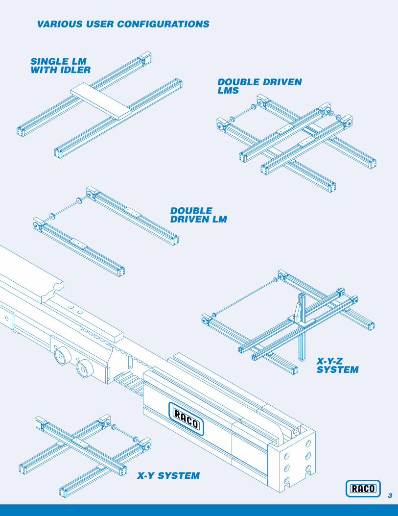
RACO’s LM Linear Modules are lightweight positioning elements, which can be easily configured into a wide varietyof multiple axis motion systems. Possible configurationsinclude single axis driven / idler, parallel linked single axis,
XY and XYZ systems. The LM is engineered for carriagespeeds to 200 inches per second, single module loadcapacity of 800 lbs. and stroke range of approximately 20 feet with a single extrusion. Further detail of the LMdesign and benefits to the motion system builder are listed below.
Features Benefits
■ T-Slots & fasteners ■ Secure mounting; Multi axis configurations
■ Selection of drive stations ■ Customize to the application
■ Mechanical or inductive switches ■ Home reference & over-travel protection
■ High strength steel reinforced belt ■ Axial forces capacity to 400 lbs
■ Cogged belt & pulleys machined to be ■ Repeatability of 0.003"to be 0° backlash
■ Precision extruded 6063 alloy ■ Travel to 20 ft without splices
■ Machined HDP (Delrin) treads & ■ Normal loads to 800 lbs.ball bearing wheels Side loads to 400 lbs.
■ External adjustment of belt & wheels ■ Easy maintenance
■ Belt seal & sealed pulley bearings ■ Service in contaminated environments
3
X-Y SYSTEM
DOUBLE DRIVENLMS
VARIOUS USER CONFIGURATIONS
X-Y-Z SYSTEM
DOUBLE DRIVEN LM
SINGLE LMWITH IDLER
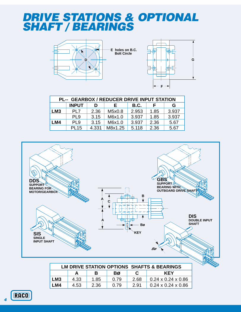
DRIVE STATIONS & OPTIONALSHAFT / BEARINGS
G
E holes on B.C. Bolt Circle
F
AC
Bø
KEY
A
4
DDSSUPPORT BEARING FORMOTOR/GEARBOX
SISSINGLE INPUT SHAFT
DISDOUBLE INPUTSHAFTBø
GBSSUPPORT BEARING WITH OUTBOARD DRIVE SHAFT
D
B
PL-- GEARBOX / REDUCER DRIVE INPUT STATIONINPUT D E B.C. F G
LM3 PL7 2.36 M5x0.8 2.953 1.85 3.937PL9 3.15 M6x1.0 3.937 1.85 3.937
LM4 PL9 3.15 M6x1.0 3.937 2.36 5.67PL15 4.331 M8x1.25 5.118 2.36 5.67
LM DRIVE STATION OPTIONS SHAFTS & BEARINGSA B Bø C KEY
LM3 4.33 1.85 0.79 2.68 0.24 x 0.24 x 0.86LM4 4.53 2.36 0.79 2.91 0.24 x 0.24 x 0.86

DRIVE / SHAFT ORIENTATION
DIMENSIONS
A+ S
TR
OK
E
Z2
Z1
5
LM UNDRIVEN IDLER UNIT
SIS PL/DDS/GBS MOVING BEAM Z LEFT RIGHT LEFT RIGHT LEFT RIGHT
LM DRIVEN UNIT DIMENSIONS ARE LOCATED ON PAGE 6
LM MOVING BEAM Z AXIS UNIT
A A ACarriage N L X# of Rollers 12 18 24LM3 16.32 19.47 23.80LM4 18.33 21.96 26.99
Carriage Rollers A Z1 Z2LM3 L 18 24.42 8.47 12.99LM3 X 24 28.74 8.47 17.32LM4 L 18 30.67 10.7 14.65LM4 X 24 35.71 10.7 19.69
A + STROKE

6
A + STROKE
STROKE LIMIT
TensionAdjustingBolts
Load AttachmentPlate
D3
Optional gearboxes available,
consult RACO
For optional carriage lengths, see carriage chart
D2
D1
D4
CD5B1
TB2
C4
C5
C4
STROKE LIMIT• •
E1E5
E2
C1
E3E1
C2C3ES3
ES1
ES4ES2E4
E6
LM CARRIAGE DIMENSIONS (Inches)ROLLERS # A C C1 C2 C3 C4 C5LM3-N 12 22.24 9.84 2.56 0.74 0.55 2.76 2.17LM3-L 18 25.39 12.99 2.56 0.74 0.55 2.76 3.74LM3-X 24 29.72 17.32 2.56 0.74 0.55 2.76 5.91LM4-N 12 26.69 11.02 3.50 0.89 0.63 3.54 1.97LM4-L 18 30.31 14.65 3.50 0.89 0.63 3.78 3.54LM4-X 24 35.35 19.68 3.50 0.89 0.63 3.94 5.91
LM EXTRUSION DIMENSIONS (Inches)E1 E2 E3 E4 E5 E6 ES1 ES2 ES3 ES4
LM3 2.95 0.79 1.97 0.98 1.77 0.89 0.16 0.41 0.10 0.26LM4 3.94 1.14 2.36 1.18 2.36 1.18 0.26 0.53 0.16 0.33
LM BASIC MODULE DIMENSIONS (Inches)B1 B2 D1 D2 D3 D4 D5 T
LM3 6.69 5.71 3.94 1.97 1.85 3.07 5.24 1.18LM4 8.90 6.77 5.67 2.83 2.36 4.65 7.48 1.38
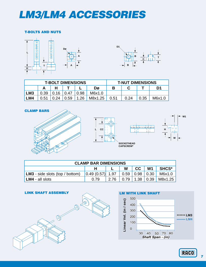
LM3/LM4 ACCESSORIEST-BOLTS AND NUTS
TH
L
CC
SOCKETHEADCAPSCREW*
L H
W
W1
A
A
Dø
CT
B
B
D1
7
Lin
ea
r V
el.
(in
/ s
ec
)
LM3••••••• LM4
••••• ••
•
CLAMP BARS
LM WITH LINK SHAFTLINK SHAFT ASSEMBLY
T-BOLT DIMENSIONSA H T L Dø
LM3 0.39 0.16 0.47 0.98 M6x1.0LM4 0.51 0.24 0.59 1.26 M8x1.25
T-NUT DIMENSIONSB C T D1
0.51 0.24 0.35 M6x1.0
CLAMP BAR DIMENSIONSH L W CC W1 SHCS*
LM3 - side slots (top / bottom) 0.49 (0.57) 1.97 0.59 0.98 0.30 M6x1.0LM4 - all slots 0.79 2.76 0.79 1.38 0.39 M8x1.25
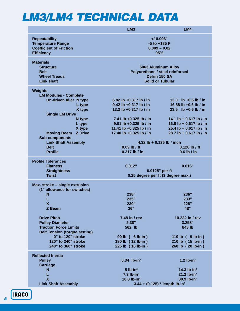
LM3/LM4 TECHNICAL DATA
8
LM3 LM4
Repeatability +/-0.003"Temperature Range -5 to +185 FCoefficient of Friction 0.009 – 0.02Efficiency 95%
MaterialsStructure 6063 Aluminum AlloyBelt Polyurethane / steel reinforcedWheel Treads Delrin 150 SALink shaft Solid or Tubular
WeightsLM Modules - Complete
Un-driven Idler N type 6.82 lb +0.317 lb / in 12.0 lb +0.6 lb / inL type 9.42 lb +0.317 lb / in 16.88 lb +0.6 lb / inX type 13.2 lb +0.317 lb / in 23.5 lb +0.6 lb / in
Single LM DriveN type 7.41 lb +0.325 lb / in 14.1 lb + 0.617 lb / inL type 9.01 lb +0.325 lb / in 16.8 lb + 0.617 lb / inX type 11.41 lb +0.325 lb / in 25.4 lb + 0.617 lb / in
Moving Beam Z Drive 17.40 lb +0.325 lb / in 28.7 lb + 0.617 lb / inSub-components
Link Shaft Assembly 4.32 lb + 0.125 lb / inchBelt 0.09 lb / ft 0.128 lb / ftProfile 0.317 lb / in 0.6 lb / in
Profile TolerancesFlatness 0.012" 0.016"Straightness 0.0125" per ft Twist 0.25 degree per ft (3 degree max.)
Max. stroke – single extrusion(1" allowance for switches)
N 238" 236"L 235" 233"X 230" 228"Z Beam 36" 48"
Drive Pitch 7.48 in / rev 10.232 in / revPulley Diameter 2.38" 3.258"Traction Force Limits 562 lb 843 lbBelt Tension (torque setting)
0" to 120" stroke 90 lb ( 6 lb-in ) 110 lb ( 9 lb-in )120" to 240" stroke 180 lb ( 12 lb-in ) 210 lb ( 15 lb-in )240" to 360" stroke 225 lb ( 16 lb-in ) 260 lb ( 20 lb-in )
Reflected InertiaPulley 0.34 lb-in2 1.2 lb-in2
Carriage N 5 lb-in2 14.3 lb-in2
L 7.3 lb-in2 21.2 lb-in2
X 10.8 lb-in2 30.9 lb-in2
Link Shaft Assembly 3.44 + (0.125) * length lb-in2

LM3/LM4 CAPACITIES
9
Th
rus
t (l
bs
)
LM3••••••• LM4◆◆◆◆◆◆
◆ ◆ ◆◆ ◆ ◆◆◆ ◆◆ ◆ ◆• •••••• •••••• ••••••••• ••• •••••••••••••
To
rqu
e (
lb-i
n)
◆ ◆ ◆◆ ◆ ◆◆◆ ◆◆ ◆ ◆
•• •••••• •••• ••••••••• ••• ••••••••••••••••
Mz
My
FzFy
Mx
Fx
AXIAL FORCE (Fx) CAPACITY
INPUT TORQUE CAPACITY
•
Rated Load Capacities LM3
Carriage Fz lb Fy lb Mx in-lb My in-lb Mz in-lbN 240 160 2750 2760 2050L 480 240 3300 3240 2400X 640 320 3500 4550 3375
LM4Carriage Fz lb Fy lb Mx in-lb My in-lb Mz in-lb
N 300 210 3540 3575 2650L 600 300 4240 4170 3090X 800 400 4500 5845 4330
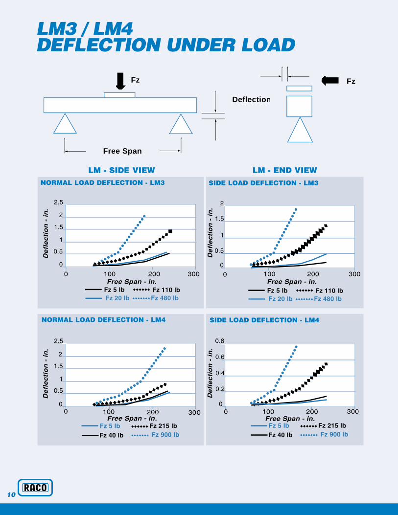
LM3 / LM4 DEFLECTION UNDER LOAD
10
•
••••
•••
◆
.
•
•••••
• •••
•
◆ ◆◆
◆◆
••
•••••
•••
•
◆ ◆
➡
Fz Fz
➡
Free Span
Deflection
•••••• •• •••• • ••••••
••
•
•
•••••••• ◆
••
•••••••
••
•••
◆◆
◆◆◆
NORMAL LOAD DEFLECTION - LM3
LM - SIDE VIEW LM - END VIEW
SIDE LOAD DEFLECTION - LM3
NORMAL LOAD DEFLECTION - LM4 SIDE LOAD DEFLECTION - LM4
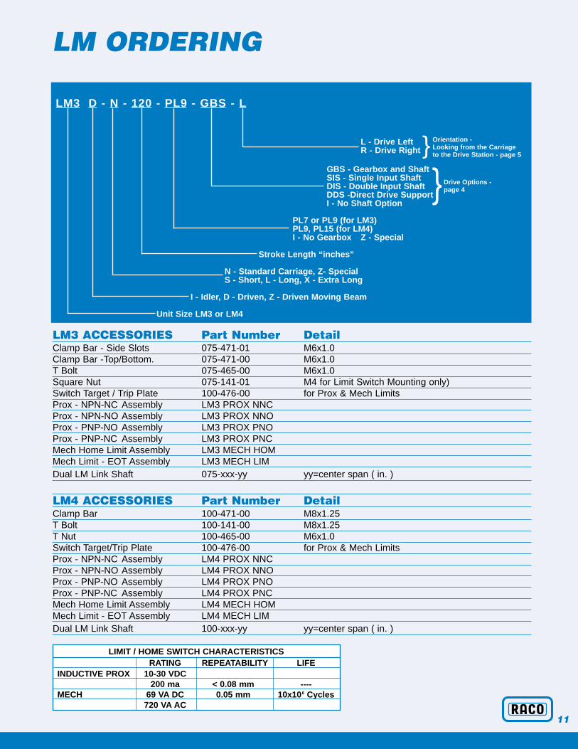
LM ORDERING
LM3 D - N - 120 - PL9 - GBS - L
L - Drive Left R - Drive Right
GBS - Gearbox and ShaftSIS - Single Input ShaftDIS - Double Input ShaftDDS -Direct Drive SupportI - No Shaft Option
PL7 or PL9 (for LM3)PL9, PL15 (for LM4)I - No Gearbox Z - Special
Stroke Length “inches”
N - Standard Carriage, Z- SpecialS - Short, L - Long, X - Extra Long
I - Idler, D - Driven, Z - Driven Moving Beam
Unit Size LM3 or LM4
11
LM3 ACCESSORIES Part Number DetailClamp Bar - Side Slots 075-471-01 M6x1.0Clamp Bar -Top/Bottom. 075-471-00 M6x1.0T Bolt 075-465-00 M6x1.0Square Nut 075-141-01 M4 for Limit Switch Mounting only)Switch Target / Trip Plate 100-476-00 for Prox & Mech LimitsProx - NPN-NC Assembly LM3 PROX NNCProx - NPN-NO Assembly LM3 PROX NNOProx - PNP-NO Assembly LM3 PROX PNOProx - PNP-NC Assembly LM3 PROX PNCMech Home Limit Assembly LM3 MECH HOMMech Limit - EOT Assembly LM3 MECH LIMDual LM Link Shaft 075-xxx-yy yy=center span ( in. )
LM4 ACCESSORIES Part Number DetailClamp Bar 100-471-00 M8x1.25T Bolt 100-141-00 M8x1.25T Nut 100-465-00 M6x1.0Switch Target/Trip Plate 100-476-00 for Prox & Mech LimitsProx - NPN-NC Assembly LM4 PROX NNCProx - NPN-NO Assembly LM4 PROX NNOProx - PNP-NO Assembly LM4 PROX PNOProx - PNP-NC Assembly LM4 PROX PNCMech Home Limit Assembly LM4 MECH HOMMech Limit - EOT Assembly LM4 MECH LIMDual LM Link Shaft 100-xxx-yy yy=center span ( in. )
} Orientation - Looking from the Carriage to the Drive Station - page 5
} Drive Options - page 4
LIMIT / HOME SWITCH CHARACTERISTICS RATING REPEATABILITY LIFE
INDUCTIVE PROX 10-30 VDC 200 ma < 0.08 mm ----
MECH 69 VA DC 0.05 mm 10x106 Cycles 720 VA AC

RACO International, Inc.3350 Industrial Blvd.Bethel Park, PA 15102(888) BUY-RACO (888) 289-7226Ph: (412) 835-5744Fx: (412) 835-0338email: [email protected] page: www.racointernational.com
© 2001 RACO International, Inc.
RACO ELECTRIC ACTUATORS FOR TODAY’S INDUSTRYOther Products Offered By RACO
RACO Compact■ Smaller installed envelope size
■ Thrust capacities to 9000 lbs.
■ Standard stroke lengths to 23.6 inches
■ Ball or acme power screw thread configuration
■ Multiple leads available in every size to optimize motor / reduction / output speed capability
■ Complete line of standard controls and options
■ ISO 9001 Manufacturing
■ Typical delivery 2-3 weeks
RACO RM■ Available in seven sizes to 10,000 lb-ft of torque
■ Fractional or multiple turn rotations
■ Output speeds thru 90 degrees in 1 to 30 seconds
■ Hollow or solid shaft output
■ Adjustable rotation limit switches
■ Analog or digital position feedback
■ Electronic torque control
■ Modular design allows custom solutions
RACO MA■ Largest installed base in the world
■ Thrust Capacities to 200,000 lbs.
■ Standard stroke lengths to 80 inches
■ Ball or acme power screw thread configuration
■ Multiple leads available in every size to optimizemotor / gearhead / output speed capability
■ Complete line of standard controls and options
■ ISO 9001 Manufacturing
■ Typical delivery 2-3 weeks
4-01