Embed Size (px)
Citation preview

I N F O R M A T I O N SCIENCES
ELSEVIER Journal of Information Sciences 106 (1998) 237 258
Linear array with a reconfigurable pipelined bus system- Concepts and applications 1
Yi Pan ~'*, Keqin Li b,2 ~' Department of ~)mputer Science, University of Dayton, Dayton OH 45469-2160, USA
b Department of Mathematics and Computer Science, State University (?]' New York, New Paltz. N Y 12561-2499, USA
Received l l Augus! 1996: received in revised form 28 January 1997: accepted 23 April 1997
Abstract
A new computational model, called a linear array with a reconfigurable pipelined bus system (LARPBS), has been proposed as a feasible and efficient parallel computational model based on current optical technologies. In this paper, we further study this model by proposing several basic data movement operations on the model. These operations include broadcast, multicast, compression, split, binary prefix sum, maximum finding. Using these basic operations, several image processing algorithms are also presented for the model. We show that all algorithms can be executed efficiently on the LARPBS model. It is our hope that the LARPBS model can be used as a new and practical par- allel computational model for designing parallel algorithms. © 1998 Elsevier Science Inc. All rights reserved.
Keywords: Basic data movement: Optics; Reconfigurable pipelined bus; Parallel algorithm; Time complexity
I. Introduction
The two major drawbacks of static networks, such as meshes and hyper- cubes, are (1) they provide limited connectivity between processors; and (2)
Corresponding author. E-mail: [email protected]. ] An earlier version of this paper appeared in Proceedings of 1996 International Conference on
Parallel and Distributed Processing Techniques and Applications, vol. IlI, pp. 1431.-1442. E-mail: [email protected].
0020-0255/98/$19.00 © 1998 Elsevier Science Inc. All rights reserved. PlI: S 0 0 2 0 - 0 2 5 5 ( 9 7 ) 1 ( l { ) 1 3-5
238 E Pan, K. Li / Journal ofln/brmation Sciences 106 (1998) 237-258
their communication diameter (the maximum distance between processors) is proportional to the size of the system. Hence, increasing the size of these net- works does not result in a further decrease in the time complexities of most par- allel algorithms running on them. The time complexities are lower bounded by the communication diameter of these networks. One way to overcome this problem is to use electronic buses for communication since they provide direct communication between any two processors in the system [20]. Processor ar- rays with various bus systems have become the focus of much interest due to recent advances in VLSI and fiber optic technologies. Arrays with a global bus [4], arrays with multiple buses [20], and arrays with reconfigurable buses [29] have been proposed for efficient computations. In an array with re- configurable buses, messages can be transmitted concurrently when the bus is partitioned into many segments, and the diameter problem in a point-to- point network disappears when all segments are reconfigured as a single global bus. Many different models have been proposed and many efficient algorithms have been implemented on such models [31-33,54,55]. Several journal special issues have also been dedicated to this topic [2,25,30,34]. However, most of the models published use electronic buses as their interconnections. When there is a large amount of message transfer between different sections of the network, the bus segments themselves become a potential bottleneck since they can only provide exclusive access for messages.
Fiber optic communications offer a combination of high bandwidth, low er- ror probability, and gigabit transmission capacity and have been used exten- sively in wide-area networks. Advances in optical and optoelectronic technologies indicate that they could also be used as interconnects in parallel computers. The ability to control optical delays precisely can be used in many ways to support high bandwidth multiprocessor interconnection. For exam- ple, precise delays can be used for the buffers required for temporal rearrange- ment of TDM signals, collision resolution in packet switched networks, and synchronization of incoming packets on separate channels. Depending upon the material through which the signals propagate, l mm corresponds to 3--7 ps. With the precision available in mechanical layout, sub-picosecond time precision is achievable. In fact, many commercial massively parallel comput- ers, such as the recently announced Cray T90 supercomputer system, use op- tical technologies in their communication subsystems. Many research papers and several journal special issues have been published on this topic [8,17,28,40].
Based on the characteristics of fiber optical communications, several re- searchers have proposed using optical interconnections to connect processors in a parallel computer system [7,26,27]. Among them, the distributed-memory Single Instruction Multiple Data (SIMD) computer with pipelined optical bus- es has received much attention [9,21,27,35,47,48] due to its simplicity and low cost. In such a system, messages can be transmitted concurrently on a pipe-
E Pan. K. Li / Journal ofh!/brmation Science,s 106 (1998) 237 258 239
lined optical bus without partitioning the bus into several segments, while the time delay between the furthest processors is only the end-to-end propagation delay of light over a waveguided bus. This design integrates the advantages of both optical transmission and electronic computation. Several slightly different models have been proposed in the literature, including the array processors with pipelined buses (APPB) [10,27], the array processors with pipelined buses using switches (APPBS) [11], the array with synchronous optical switches (ASOS) [48], and the reconfigurable array with ~panning optical buses (RASOB) [49]. Many parallel algorithms, such as the Hough transform [35], singular val- ue decomposition [39], order statistics [37], sorting [10], matrix operations [49], and some numerical algorithms [13], have been proposed for these models. The preliminary work indicates that arrays with pipelined buses are very efficient for parallel computation due to the high bandwidth within a pipelined bus sys- tem.
More recently, arrays with reconfigurable optical buses have been proposed and studied independently by Pavel and Akl [45,46], and Pan and Hamdi [38]. In these models, message can be transmitted concurrently on a bus in a pipe- lined fashion and the bus can be reconfigured dynamically under program con- trol to suit communication needs. Currently, two related models have been proposed. They are: linear arrays with a reconfigurable pipelined bus system (LARPBS) proposed by Pan and Hamdi [38] and arrays with reconfigurable optical buses (AROB) proposed by Pavel and Akl [45]. Many algorithms have been designed for these two models, including inversion number computation, selection, and quicksort algorithms on the LARPBS model [18,37,38], and ma- trix multiplications, selection, and sorting on the AROB model [42-44,50]. Al- though the two models are similar to some extent, a fundamental difference exists between them. In the LARPBS model, counting is not allowed during a bus cycle, while it is permitted in the AROB model. In fact, the LARPBS does not allow any processor involvement during a bus cycle, except setting switches at the beginning of a bus cycle. Unlike many theoretical models, such as PRAM, we believe that the LARPBS model is implementable and practical using current optical technologies.
In this paper, we furlher investigate the LARPBS model. First, we describe several new fundamental data movement operations for the LARPBS model. In particular, an efficient algorithm for computing the binary prefix sum is pro- posed. Then, several image processing algorithms are presented for the LAR- PBS model. We show that all algorithms can be executed efficiently.
2. The LARPBS model
A pipelined optical bus system uses optical waveguides instead of electrical buses to transfer messages among electronic processors. The advantages of
240 E Pan. K. Li / Journal o f Information Sciences 106 (1998) 23~258
using waveguides can be seen as follows. Besides the high propagation speed of light, there are two important properties of optical signal (pulse) transmission on an optical bus, unidirectional propagation and predictable propagation de- lay per unit length. These two properties enable synchronized concurrent ac- cess of an optical bus in a pipelined fashion. [9,27,47,48]. This, combined with the abilities of a bus structure to do efficient broadcasting or multicasting, makes the architecture suitable for many applications that involve intensive communication operations.
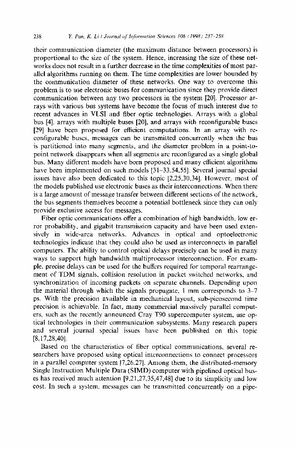
Fig. 1 shows a linear array in which electronic processors are connected with an optical bus. Each processor is connected to the bus with two directional couplers, one for transmitting on the upper segment and the other for receiving from the lower segment of the bus [9,27,47,48]. The optical bus contains three identical waveguides, one for carrying messages (the message waveguides) and the other two for carrying address intbrmation (the re/erence waveguide and the select waveguide), as shown in Fig. 2. For the purpose of simplicity, the mes- sage waveguide, which resembles the reference waveguide, has been omitted from the figure. Messages are organized as fixed-length message Jmmes. Note that optical signals propagate unidirectionally from left to right on the upper segment and from right to left on the lower segment. This bus system is also referred to as the folded-bus connection in [9].
Let ~ be the pulse duration in seconds and ct, the velocity of light in these waveguides. Define a unit delay A to be the spatial length of a single optical pulse, that is A =-(o × ~:~. Initially, processors are connected to these three waveguides such that between any two given processors, the same length of fi- ber is used on all three waveguides. Hence, the propagation delays between two processors are the same for all three waveguides. A bus cycle for an optical bus is defined as the end-to-end propagation delay on the bus; i.e., the time taken for an optical signal to propagate through the entire bus. It' r is the time taken
ID,
( ~ Processor ] I Direc t iona l Coup le r
Fig. 1. A linear optical bus system of N processors.
K Pan, K. Li/Journal q/h?/brmation Sciences 1¢16 (1998)237 258 241
D @ @ m / ©./.
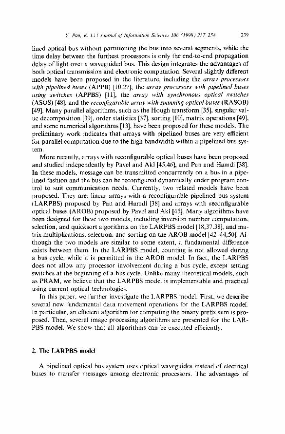
D Reference Pulse I Select Pulse Fig. 2. An optical bus with delays added.
Delay
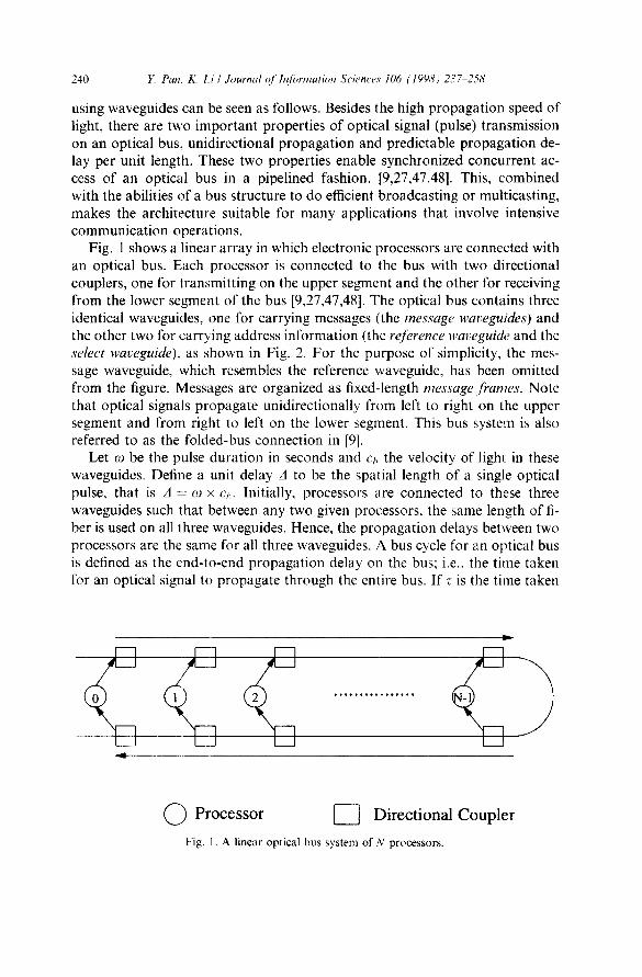
for a signal to traverse the optical distance between two consecutive processors on the bus, then the length o f a bus cycle for the system of Fig. 1 is 2Nz. We then add one unit delay A (shown as a loop in Fig. 2) between any two proces- sors on the receiving segments o f the reference waveguides and of the message waveguides. Each loop is an extra segment o f a fiber and the amount of' delay added can be accurately chosen based on the length of the segment. As a result, the propagat ion delays on the receiving segments o f the select waveguide and the reference waveguides are no longer the same. Finally, we add a condit ional delay A between any two processors i and i ...i-- l, where 0 ~ i..~ N - 2, on the transmitt ing segments o f the select waveguides (Fig. 2). The switch between processor i and i +. I is called S(i + 1 ) and is local to processor i + 1. Thus~ ev- ery processor has its own switch, except processor 0. The condit ional delays can be implemented using 2 x 2 optical switches such as the Ti:LiNbO3 switch- es used in an optical computer [3]. Each switch can be set by the local processor to two different states: straight or cross as shown in Fig. 3. When a switch is set to straight, it takes z time for an optical signal on the transmitting segments o f the select waveguides to propagate from one processor to its nearest neighbor. When a switch is set to cross, a delay ~o is introduced and such propagat ion will take r + ~o time. Clearly, the maximum delay that the switches can introduce is the durat ion o f N - 1 pulses.
C) C)
Fig. 3. Conditional delays implemented using 2 × 2 optical switches.

242 E Pan, K. Li / Journal c~(h~[brmation Sciences 106 (1998) 237.258
Messages transmitted by different processors may overlap with each other even if they propagate unidirectionally on the bus. We call these message over- lappings transmission conflicts. Assume each message has b binary bits, each bit represented by an optical pulse, with the existence of a pulse for 1 and the ab- sence for 0. To ensure that there are no transmission conflicts, the following condition must be satisfied, r > N:o, where r is the time taken for a signal to traverse the optical distance between two consecutive processors on the bus, and ~9 the pulse duration. Note that the above condition ensures that each mes- sage can fit into a pipeline cycle such that in a bus cycle, up to N messages can be transmitted by processors simultaneously without collisions on the bus. In a parallel array, messages normally have very short length; i.e., b is very small. Thus, in the following discussion, we assume that the above condition is always satistied and that no transmission conflicts are possible as long as all processors are synchronized a! the beginning of each bus cycle.
Now let us describe the LARPBS model. In the LARPBS, we insert an op- tical switch on each section of the transmitting bus and receiving bus. Thus, each processor has six more local switches, three on its three receiving segments and three on its three transmitting segments, besides its switch for conditional delay. The switches on the receiving and transmitting segments between proces- sors i and i + 1 are called RSR(i) and RST(i), respectively, and are local to pro- cessor i as shown in Fig. 4. Here, RSR(i), 0 <~ i < N are 2 x l optical switches, and RST(i), 0 ~.~ i < N are 1 x 2 optical switches. In the :following discussion, these switches will be called reconfigurable switches due to their function. When all switches are set to straight, the bus system operates as a reg- ular pipelined bus system. When RSR(i) and RST(i) are set to cross, the whole bus system is split into two separate systems, one consisting of processors 0.1 . . . . . and i and the other consisting of i + 1, i + 2 , . . . , N - I. The total de- lay for a signal passing the transmitting segment, the optical fiber between
( ~ Processor - ~ 1X2 Switch ~ 2X1 Switch
Fig. 4. The LARPBS model of size 6 with two subarrays.

E Pan, K. Li/,hmrnal ~[h¢[brmation Sciences 106 (t998) 237 258 243
RST(i) and RSR(i), and the receiving segment is made to be equal to r. Hence, the array with processors 0 to i can operate as a regular linear array with a pipelined bus system; so does the array with processors i + 1 to N -- 1. Fig. 4 shows the LARPBS model with six processors. The array is split into two sub- arrays, with the first one having four processors and the second one having two processors. In the figure, only one waveguide is shown. Conditional switches are omitted in the figure to avoid confusion.
Several time-division switching methods can be applied to route messages in an optical bus system. In the first approach, each processor is assigned a fixed time slot and transmits or receives a message during that particular time slot. A sequence of time slots formed on the transmitting segment of a bus is rear- ranged via a time-slot interexchanger [51], and then forwarded to the receiving segment. Each time slot of the output sequence contains a message destined to the processor corresponding to that slot. In the second approach, each proces- sor is assigned a fixed transmitting time slot. An SIMD environment is as- sumed in this case. Hence, each processor knows which processor is sending a message to it and knows the time slot that contains the message [9,27]. The last approach is to use a coinc4dent puls'e technique [5,10,47]. Using this ap- proach, the relative time delay of a select pulse and a reference pulse is deter- mined so that they will coincide, thus producing a double-height pulse, only at receiver i. By properly adjusting the detecting threshold of the detector at pro- cessor i, this double-height pulse can be detected, thereby addressing i.
In this paper, the coincident pulse technique is used to route messages or to broadcast messages on the bus. The switches on the sending segments are used to conditionally delay the select pulses and can be closed or opened by the local processors (see Fig. 2). Now let us discuss in detail how to perform several ba- sic data movement operations on the LARPBS using the coincidence pulse technique. Here we assume that the message processing time is roughly equal to the time for a bus cycle. If a basic operation takes a constant time, then a bus cycle also requires a constant time. This assumption has also been used by many other researchers [1,10,12,14,18,24,46,48-50]. Hence, all times in the following discussion are measured in bus cycles.
Obviously, accurate delays are critical in the LARPBS model. In a practical system, there are some uncertainties in the timings. A pulse travelling from one processor to the next will not take a time exactly r. These errors may accumu- late when the number of processors is large. Because the system relies on the precise timings for addressing messages, the error will eventually prohibil fur- ther scaling. This scalability problem is discussed in [6] and is called synchro- nization error by the authors of [6]. Some experiments have been carried out and the results indicate that large variations (on the order of one half of a pulse width) can be tolerated without significant degradation of the coincident signal [6]. For single-mode fibers with a length of a few kilometers, the synchroniza- tion error is small enough and can be tolerated. Hence, using current technology,
244 E Pan. K. l.i / Journal O[b~formation Sciences 106 (1998) 237 258
a system using a few thousands of processors will not present any problem. For more discussion on this topic, the reader is referred to [16].
3. Basic data movement operations
In this section, we provide preliminary facts and results which will be used in the future discussion. Some of the operations were reported previously and are included here for the purpose of completeness.
3.1. One-to-one communica t ion
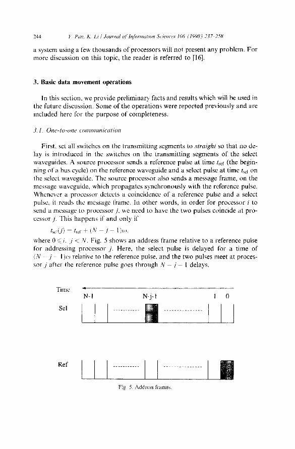
First, set all switches on the transmitting segments to straight so that no de- lay is introduced in the switches on the transmitting segments of the select waveguides. A source processor sends a reference pulse at time tref (the begin- ning of a bus cycle) on the reference waveguide and a select pulse at time tsd on the select waveguide. The source processor also sends a message frame, on the message waveguide, which propagates synchronously with the reference pulse. Whenever a processor detects a coincidence of a reference pulse and a select pulse, it reads the message frame. In other words, in order for processor i to send a message to processor./, we need to have the two pulses coincide at pro- cessor j. This happens if and only if
t~d(j) -- t~,j, + (N - / - 1)(~),
where 0 <~ i. j < N. Fig. 5 shows an address frame relative to a reference pulse for addressing processor j . Here, the select pulse is delayed for a time of (N - j - 1 )(J relative to the reference pulse, and the two pulses meet at proces- sor j after the reference pulse goes through N - j - 1 delays.
Time N-I N-j-1 1 0
Sel . . . . . . . . . . . I . . . . . . . . . . . . . . . J
Ref
........... I ............... F | Fig. 5. Address fi'ames.

E Pan. K. Li / Jmtrnal qfIn/brmation Sciences 106 (1998) 2 3 ~ 5 8 245
Hence, for a given reference pulse transmitted at time tref, the presence of" a select pulse at time t,-ef + (N - j - 1)¢~ will address processor j while the ab- sence of a select pulse at that time will not. For example, if a processor wants to send a message to processor 0, it sends a reference pulse at time t,.ef (the be- ginning of a bus cycle) and a select pulse at t~l = tref + (N - l)~o. Since there are (N - 1) unit delays in the receiving segments of the reference waveguide, these two pulses will coincide at processor 0. In order for a processor to address processor N - 1, tsel = t,.ej" + ( N - ( N - 1) - 1)~zJ = tref; i.e., the source proces- sor has to send a reference pulse and a select pulse at the same time. Clearly, the two pulses coincide at processor N - 1 since there is no delay in its receiving segment of the reference waveguide.
3.2. B r o a d c a s t
All conditional switches are set to s t r a ( g h t , thus introducing no delay on the transmitting segments (see Fig. 6). The source processor sends a reference pulse at the beginning of its address frame. As described previously, the presence or absence of a select pulse determines if a processor should read the correspond- ing message. Thus, if the source processor sends N consecutive select pulses in its address frame on the select waveguide, as shown in Fig. 7, every processor on the bus detects a double-height pulse and thus reads the message. 'This is clearly a broadcast operation. For example, when processor 0 in Fig. 6 wants to broadcast a message, it sends a reference pulse at the beginning of its address frame on the reference bus and five select pulses in its address frame on the se- lect bus. The first select pulse will meet the reference pulse at processor 4 since both pulses meet no delay on their buses. The second select pulse will meet the reference pulse at processor 3 since the select pulse meets no delay on the select bus and the reference pulse goes through one delay on the reference bus. The
D
© © © © \ D R e f e r e n c e Pu l se I Se l ec t Pu l s e D e l a y
Fig. 6. Switch settings ffw a broadcast operation.

246 E Pan, K Li / Journal o f b?/ormation Sciem'es 106 (1998) 237 ..258
Time "
Sel
N-I j 1 0
I ........... l ............... m
Ref
. . . . . . . . . . . . . . . . . . . . . . . . . . i l::ig. 7. Address lYames for broadcasting.
last select pulse will meet the reference pulse at processor 0 since the select pulse meets no delay on the select bus and the reference pulse goes through four de- lays on the reference bus.
3.3. Multicast
Multicast is a one-to-many communication operation. Each processor may send a message to a group of processors in the system. Each processor receives only one message from a source processor during a bus cycle. This operation can be implemented in the following way. All conditional switches are set to straight, thus introducing no delay on the transmission segments (see Fig. 6). Each source processor sends a reference pulse at the beginning of its address fi'ame. If a source processor sends several select pulses in its address frame on the select waveguide as shown in Fig. 7, the corresponding processors on the bus detect a double-height pulse and thus read the message.
3.4. Compression
Assume an array of N data elements with each processor having one data element. Also, assume that the number of active data elements in the array is s. Active elements are labeled based upon certain values of their local vari- ables, A processor with an active element is referred to as an active processor. The compression algorithm moves these active data elements to processors N - s - I. N - s . . . . . N - 1. In other words, the compression algorithm moves all active data items to the right side of the array. In the following discussion, we assume that all active processors have their local variables X(i) set to 1. In addition, we can also require the acnve elements remain in the same order, leading to tile ordered compression problem. The ordered compression algo- rithm is implemented as follows. First, processor i sets its local switch S(i) to cross if X(i)= 1, and to straight if X(i)= 0. Then, processor i, whose

E Pan, K. Li/Journal o1 h!/brmatkm Sciences 106 (1998) 237 258 247
X(i) = 1, injects a reference pulse on the reference waveguide and a select pulse on the select waveguide at the beginning of a bus cycle. A processor also sends a message f rame containing its local da ta in m e m o r y location D through the message waveguide during the bus cycle. Processors with X ( i ) = 0 do not put any pulse or message ola the three waveguides. In other words, every active processor tries to address processor N - 1. The select pulse sent by the proces- sor whose index is the largest in the active set passes no delay in the t ransmit- ring segments because all the processors to its right are not in the active set and their corresponding switches are set to straight. Thus, the two pulses will meet only at processor N - 1, and the corresponding message is picked up by pro- cessor N - 1. Similarly, the select pulse sent by the processor whose index is the second largest in the active set passes one condit ional delay in the t ransmit- ting segments because only one processor to its right is in the active set and its corresponding switch is set to cross. Since both the select and reference pulses pass one delay on the select and reference waveguides when arriving at proces- sor N - 2, the two pulses will meet only at processor N - 2. Hence, processor N - 2 receives the da ta item f rom the processor whose index is the second larg- est in the active set. 113 general, the select pulse sent by the processor whose in- dex is the kth largest in the active set passes k condit ional delays in the t ransmit t ing segments on the select waveguide because k processors to its right are in the active set and their cor responding switches are set to cross. Since both the select and reference pulses pass k delays on the select and reference waveguides when arriving at processor N - k, the two pulses will meet only at processor N - k. Clearly, this is the compress ion operat ion. Hence, the or- dered compress ion problem can be pe r fo rmed o:n a L A R P B S with N processors in one bus cycle.
A similar a lgor i thm called compaction is obta ined independently by Pavel and Akl [45]. However , their a lgor i thm requires several bus cycles since it per- forms a binary prefix sum first followed by a permuta t ion routing. Our algo- r i thm requires only one bus cycle.
3.5. Split
In a split operat ion, it is desired to separate the active set f rom the inactive set. In other words, all data elements D(i), 0 <~ i <~ N - 1, whose X(i) = 1 are moved to the upper par t o f the a r ray P E ( N - s ) , P E ( N - s + 1) . . . . . PE(N - 1), and all da ta elements D(i), 0 <~ i ~< N - 1, whose X(i) = 0 are moved to the lower par t o f the ar ray PE(0), PE(1) . . . . . P E ( N - s - 1), where s is the number of elements in the active set. In other words, D(i) is moved to DO'),
\~N-1 B(k) i fX( i ) = 1 and D(i) is moved to D(j) , where where j = N - 1 - ,~,~::=i~ 1 v ~i..-1 Xfk~ J=z_~k::0 ~ l i f X ( i ) = : O .
The split operat ion is pe r fo rmed as follows. First, we label processor i whose X(i) = 1 as active; i.e., set X(i) to 1 if and only if X ( i ) = 1. We call the
248 E Pan, K[Li /Journal qfh~[ornlation Sciences 106 (1998) 237 258
compress ion algori thm to move all da ta elements in the active set to the upper par t of the array. To avoid destroying the original da ta items in D, we copy them to a new m e m o r y location DI. Second, we label all processors whose X(i) = 0 as active; i.e., set X(i) to 1 if and only if X(i) = 0. Then, we call the compress ion a lgor i thm to move all data elements in the set to the upper par t o f the array. To avoid destroying the da ta items in D and D~, we copy them to a new memory location D2. Third, move all data items in memory location D2 left s positions. This is a normal data t ransfer opera t ion and can be carried out in one bus cycle. Finally we copy all moved da ta f rom t empora ry locations D1 or D2 to their cor responding local locations D. Hence, the split opera t ion can be per formed on an LARPBS with N processors in O(1 bus cycle.
3.6. Binary pro:fix sum
Consider an L A R P B S with N processors and N binary values t'i, 0 < ~ i , < , N - 1. Tile binary prefix sum requires the computa t ion of psum~ = v0 + vl-~ . . . . . . . + v, t, for all 0<~ i 4 N - 1. This p rob lem has been in- vestigated by Pavel and Akl [45] and it is shown that O(1) t ime is needed to solve the prob lem on an AROB. The idea behind their a lgor i thm is as follows. Processor 0 initiates a pair of pulses on the selection and reference waveguides. The time difference between the two pulses is incremented with one unit delay at each processor which has a 1 as input value. The select pulse arrives at the ith processor with k t ime-units delay relative to the reference pulse, where k is the number of l-values stored by the processors with indices smaller than i, i.e., p sumi = k. The relative delay between two pulses is detected by each processor through a counter. The drawback with this scheme is that a high speed counter is required to count the relative delays between two pulses. In our opinion, it is impract ical for an electronic processor to match the speed of an optical bus.
In this paper , a new approach is proposed to avoid this problem. We will show that the binary prefix sum can be done in O(1 ) bus cycle on an L A R P B S without involving high speed counters. In fact, during a bus cycle, no process- ing is involved. Hence, as long as the processor speed matches the speed of a bus cycle, this scheme works. This also explains why a bus cycle can be consid- ered a constant time.
First, processor i, 0 ~ i < N - 1, sets its switch S(i) on the t ransmit t ing seg- ment to straight if ai = 1, and cross if ai = 0. Second, processor i, 0 ~< i < N - 1, injects a reference and select pulse on the reference and select bus, respectively, at the beginning of a bus cycle. In other words, all processors try to address processor N - 1. Thus, a train of N - 1 address f rames pass through the bus system. Now, let us consider a part icular address f rame sent by processor i, which will be called address frame i in the following discussion. If processor j detects the coincidence of the reference pulse and the select pulse in address f rame i, then ~ x I ,:::::i~ i x, = N -- 1 - j . This can be explained as fol-

E Pan, K. Li / .lournal o/In/brmation Sciences 106 (1998) 237...258 249
lows. Suppose that all processors to the right o f processor i contains 0, all switches to the right o f processor i on the select waveguide are set to straight, and thus no delay is introduced. As a result, the two pulses f rom processor i will coincide at processor N - 1. Suppose that only one processor to the right o f processor i contains a 1, only one switch to the right o f processor i on the select waveguide is set to cross, and thus only one unit delay is introduced. As a result, the two pulses f rom processor i will coincide at processor N - 2. In general, when N - 1 - j processors to the right o f processor i contain a 1, N - 1 - j switches to the right o f processor i on the select waveguide are to cross. Since there are N - 1 - j unit delays on the select waveguide, the two pulses f rom processor i will coincide at processor. / . After this bus cycle, proces- sor j simply sends a message containing its own address to processor i. Notice that it is possible that a processor may detect the coincidence of two pulses in several address frames. A naive method is to let processor j pick up all the mes- sages and mult icast a message to all those sending processors. This scheme is impract ical since it requires an electronic processor to match the t ransmission speed of an optical bus.
To avoid this, a better method is adopted here. Assume that processors s and t contain a 1 and all processors between them contain a 0. Also assume that processor j receives a message f rom t. Clearly, processor j should also re- ceive messages f rom processors s + 1, s + 2 , . . . , t - 1 using the naive method. In the new scheme, we let processor j pick up only the message when detecting the coincidence of two pulses the first time, and ignore the remaining coinci- dence of two pulses. Hence, processor j picks up a message only f rom t and sends a message only to t. However , since processors s + 1,s + 2 . . . . , t - 1 should receive the same message as t does, we can simply split the bus at posi- t ion t and let t b roadcas t the received message, which contains an address j , to processors s + 1, s + 2 . . . . . t - 1 in a bus cycle. In this way, all processors send (or receive) one message during a bus cycle.
Finally, when processor 0 receives a message containing an address j , it first calculates the sum of all binary numbers in the ar ray y = x0 + (N - 1 - j ) , and broadcas ts it to all processors on the bus. Processor i then gets its part ial sum xo + xi + x2 + . . . + x~ = 3 ...... (N - 1 - j ) . Thus, the binary prefix sum on the L A R P B S can be computed in O ( l ) time.
3.7. General sorting
A quicksort a lgor i thm of N elements is p roposed for the L A R P B S model of size N in [38] and runs in O ( l o g N ) expected time. The div ide-and-conquer strategy is applied to solve the sort ing p rob lem recursively. Suppose that C is the input a r ray for a call to the sorting algori thm. In every iteration, we part i t ion the set C into three disjoint subsets Cj = { c E C [ c < v}, 6'2 = {c ~- C [ c = v} and 6':~ := {c E C I c > v}, where v is the pivot value of C. We

250 Y. Pan, K Li / Journal t~f lnJbrmation Sciences 106 (1998) 237--258
move all elements in C1 to the left side of the array and move all elements in C3 to the right side of the array. Then, we divide the array into three smaller sub- arrays each with a size of ]C~ I, Ic2l, and 1C3] respectively, and apply the same algorithm to the two subarrays containing Ci or C3. In this manner we can re- place the given problem by two identical problems of smaller size. The main step used in each iteration is a split operation, and takes O(1) bus cycles. Since the total average number of iterations of the quicksort algorithm for a set of size N is at most O(log N) [38], the total expected time of the sorting algorithm is O(logN) time.
3.8. Integer sorting
The quicksort algorithm is suitable for general keys. If we restrict the values to integers, a radix sorting algorithm can be used. We show here that a LARPBS with N processors can sort N integers with k bits in O(k) steps. The basic idea is to repeat the split algorithm k times, and each time uses the /th bit as the mark for the active set, where 0 ~< 1 < k. After k iterations, all N integers are in sorted order. Similar results are described in [44,50] for AROB with counting capability. Pavel and Akl have also shown that a better result can be obtained if counting is allowed during a bus cycle [44].
3, 9. Selection
A selection algorithm for the LARPBS is described in [37]. The basic idea behind the algorithm is to pick a random element as the "pivot" element and partition the input into two around the pivot; decide which partition the ith element is in; throw away the irrelevant partition and perform an appropri- ate selection in the relevant partition. Further, if the number of elements is much larger than the size of the LARPBS, the algorithm is still quite scalable. It is shown that the selection problem (from out of N elements) can be solved in O(N log N/p) expected number of bus cycles on an LARPBS of size p [37]. A selection algorithm using O( l ) time with high probability on a 2D AROB with counting capability is also described in [50].
3.10. Maximum finding
Maximum finding can be carried out through the above sorting or selec- tion algorithms. This requires either O(logN) expected time or O(k) time. In this section, we show that it is possible to find the maximum of N numbers in constant time on an LARPBS of size N2/2. The algorithm is not practical since it uses too many processors for such a simple problem. However, it is the basis of our improved maximum finding algorithm whose time complexity is O(log logN) cycles using N processors.

Y. Pan. K. Li / Journal o['lnformation Sciences 106 (1998) 23~258 251
Let us first discuss the implementation on an LARPBS with N2/2 proces- sors. Initially, processors i, 0 ~< i < N, hold the N numbers. We divide the array into N segments with each having N/2 processors. The first segment, i.e., pro- cessors i, 0 ~< i < N/2, multicast their data to their corresponding processors in other N - 1 segments. The second segment, i.e., processors i, N/2 <~ i < N, mul- ticast their data to their corresponding processors in other N - 1 segments. So far, each processor receives two numbers. We reconfigure the whole array into N segments. Then processor i/2 in segment i, 0 ~< i < N, broadcasts its local larger to other processors in its own segment. Each processor compares the re- ceived one with its local larger and marks its local variable B = 0 if the received one is larger, and B = 1 if smaller. A binary sum is performed over each seg- ment. I f a segment whose sum of B values is 0, the broadcast value in the seg- ment is the largest one in the array.
Now let us turn to solving the problem of finding the maximum of N num- bers on a linear array of size N. The method described below is based on the work by Kucera [19]. We partition the input into groups so that enough pro- cessors can be allocated to each group in order to find the maximum of that group in constant time by the above algorithm. As the computation progresses, the number of candidates for the maximum is reduced. This implies that the number of processors available per candidate increases, and so the group size can be increased. I f the group size is s, then ,52/2 processors are needed to find the maximum of that group in O(1) time. At the first stage, the size of each group is 2 and the maximum of each group can be found by one local compar- ison. At the second stage, we still have N processors, but the number of candi- dates has been reduced to N/2. We can make the size of each group 4 and have N/8 groups. Thus we allocate 8 processors per group which is sufficient for a group of size 4. At the third stage, tile number of candidates has been reduced to N/8. We can make the size of each group 16 and have N/(8 x 16) groups. Thus we allocate 128 processors per group which is sufficient for a group of size 16. At the fourth stage, we have N/(8 x 16) remaining candidates. We can make the size of each group 256 and have N/(8 × 16 x 256) groups and allo- cate 32 768 processors per group. The above process can continue until only one candidate is left which is the maximum. Clearly, the size of the group can be squared at each stage. This implies that after O(log logN) stages the maximum of the whole list can be found. Since each stage uses a constant num- ber of cycles, finding the maximum of N numbers can be computed in O(log log N) steps on an LARPBS of size N.
4. Applications
We are now in a position to show how the dynamic reconfigurability and the property of pipelined message transmission on the bus can be exploited for the
252 E Pan, K, L i t Journal oflnJbrmation Sciences 106 (1998) 237-.258
purpose of designing efficient parallel application algorithms. In this section, we show that a number of important tasks that involve computing basic descriptors of digitized images can be computed efficiently on the LARPBS model. These descriptors include the median row, the area, the perimeter, and the histogram of an image. Hough transform of an image on the LARPBS is also discussed.
4.1. Median row
The median row problem [53] can be stated as follows. Let P(i,j) be a 0/1 valued matrix representing a digitized picture. The median row is defined to be the row where roughly half the l 's are above it and roughly half are below it. That is, we are interested in finding row
v N 12 N I / 2 NI;2 I m, .=min x Z ~ P ( i , j ) >~ Z Z P(i'j) " (1)
t : : : l / :=1 * x f l / ]
Initially, processor k contains P(i,j), where k = (i - 1) x N U2 +j. The me- dian problem can be solved by first performing a binary prefix sums. The sum of all l 's is broadcast to the whole array. Thus, each processor can calculate the sum of l 's above it and below it. Each processor containing the last pixel in a row checks the inequality in Eq. (1) and marks itself in a variable B (initially B = 0) if the inequality in Eq. (1) is satisfied. Apparently, all rows equal to or below the median row satisfy the inequality in Eq. (l). To find median row, we count the number of rows which mark themselves by summing all B's. Clearly, all the above operations use O(1) steps. Thus, the median row of a binary image of size N 1/2 x N 1/2 can be computed in O(1) steps on an LARPBS of size N.
4.2. Area and perimeter
The area of a grey-level image is defined as the number of pixels whose grey- level intensity exceeds a certain threshold. For a binary image, the area corre- sponds to the number of I pixels in the image. The boundary of the image is the set of all pixels with neighbors both below and above the threshold. The perim- eter of an image is the length of its boundary, i.e., the number of pixels on the boundary.
Clearly, computing the area of a digitized image can be reduced to instances of computing the prefix sums of all N I/2 x N 1/2 pixel values in the image. To see that this is the case, we let every processor in an LARPBS write a I or 0 into a local variable, depending on whether or not the grey level intensity of the pixel it holds is above or below the threshold. To compute the perimeter of the image, we need to compute the boundary of the image. Although the im-

E Pan, K Li/Journal of Infi~rmation Sciences 106 (1998) 237-258 253
age is 2-dimensional and the processor array is 1-dimensional, we can calculate the processor indices of the neighbors of a pixel easily based on the mapping described earlier; i.e., processor k contains pixel P(i, j) in the image, where k = (i - 1) × N 1/2 +/ . Thus, checking that four neighbors of a pixel corre- sponds to four one-to-one communications discussed above and can be done in O(1) time. We let every processor in an LARPBS write a 1 or 0 into a local variable, depending on whether or not the pixel is on the boundary via check- ing its neighbors' pixel values. Therefore, computing the perimeter of the image is reduced to computing the number of boundary pixels, which can be done through the binary prefix sum algorithm. Consequently, both the area and the perimeter of a digitized image of size N 1/2 × N t/2 can be computed in O(1) steps on an LARPBS of size N.
4.3. Histogram
Consider a digitized image containing h grey-level intensities. The histogram of the image tells us how often each grey level occurs in the image. As explained in [52], the histogram provides an estimate of the grey-level probability density in the ensemble of images of which the one at hand is a sample. To compute the histogram of an N 1/2 × N 1/2 digitized image on an LARPBS of size N, we could proceed to compute the number of pixets at each grey level one by one. Using the binary prefix sum algorithm, the overall time complexity is O(h). Now, let us discuss a more efficient algorithm for computing the histo- gram. We first sort the pixels based on the grey levels of the pixels in the image. Then, processor i, 0 < i ~ N - 1, compares its grey level with that of processor i + 1. If the two grey levels are different, disconnect the bus between processors i and i + I. Thus, the bus system is divided into h subbus systems with each seg- ment containing pixels of a particular grey level. Now, we perform a binary prefix sum over each subbus system using the algorithm described above. Since the integer sorting algorithm uses O(log h) time, the time complexity of the his- togram algorithm is O( log h).
4.4. Hough transJorm
The Hough transform of an image is a set of projections of the image taken from different angles. Specifically, the image is integrated along line contours defined by the equation
{(x,y): x cos (0) + y sin (0) = p}, (2)
where 0 is the angle of the line with respect to the positive y-axis and p the (signed) distance of the line from the origin. Normally, it is assumed that each line contour is approximated by a band that is one pixel wide. All of the pixels that are centered in a given band will contribute to the value of that band.

254 E Pan, K. Li / Journal ~]" lnjormation Sciences 106 (1998) 237....258
Because each band is one pixel wide, there are at most 2J/eN I/2 values of p for each value of 0 in an N j/2 x N 1/2 image. In general, each band could be several pixel wide and is determined by Rres, the resolution along the p direction. The parameter n will be used to denote the number of projections (values of 0) that are to be calculated. The Hough transform is an important curve-detection method based on a relation between points lying on a line or curve in the image space and the parameters of that line or curve [15]. Under this translbrmation, collinear edge pixels are mapped into the same point in the parameter space. If the parameter space is quantized into n 0 values, 00, • • •, 0,,-1, and n p values, Po , . . . , P,,-1, a (0, p) pair would correspond to a linear band of edge pixels, ap- proximating a line. Thus, detecting lines reduces to detecting points in the pa- rameter space to which a large number of pixels are mapped.
The Hough transform can be performed on an LARPBS of N processors. Assume that each processor holds the indices of a pixel in an N )/2 x N j/2 im- age. For each angle value 0i, 0 <~ i < n, each processor performs the following steps. First, each processor calculates the distance p of the line from the origin using Eq. (2); second, we sort the N pixel values in the array based on their cor- responding p values; third, we divide the LARPBS into n subarrays where each subarray contains the same p values; fourth, we perform a binary sum of the pixel values over each subarray. All steps use O(1) time except step three which uses O( log n) through the radix sorting algorithm. Hence, the total time of the Hough transform algorithm is O(n log n) bus cycles. If we use an LARPBS with nN processors, then the total time of the Hough transform algorithm can be reduced to O(log n) cycles. If we are given N edge pixels instead of a whole image as the input [36,41], we can also solve the Hough transform prob- lem in O(n log n) (or O(log n)) time on an LARPBS with N (or An.) processors.
5. Conclusions
Optical interconnections offer the potential for gigahertz transfer rates in an environment free from capacitive bus loading and electromagnetic interference. The effectiveness of optical interconnections has been examined from both the- oretic and practical perspectives [7,26,27]. Over the past decade, much research has focused on applications to wide-area networks. Recently, pipelined optical buses have been proposed in the literature to connect processors in parallel computer systems and many experiments show that it is a feasible solution to the low bandwidth problem exhibited in an electronic bus system [9,21,27,47,48]. More recently, reconfiguration has been introduced into pipe- lined bus systems and models using reconfigurable pipelined optical buses have been proposed. Many parallel algorithms have also been proposed :for arrays with a pipelined optical bus system [13,35,37,39] and arrays with reconfigurable optical buses [38,45].

Y. Pan, K Li / Journal of lnJormation Sciences 106 (1998) 237-?58 255
In this paper, we have proposed several basic data movement operations on the LARPBS model and shown that these operations can be computed effi- ciently in the communication system (the reconfigurable pipelined optical bus) without involving any processor execution during a bus cycle. This is cru- cial because the processing speed of a processor is much slower than the optical bus, and it is impossible to perform even simple computations such as counting during a bus cycle. This is also the major difference between the LARPBS mod- el described in [38] and this paper and the AROB model used in [45,50].
Unlike many theoretical models, such as the PRAM, the LARPBS model is implementable and practical using current optical technologies. Due to its high communication bandwidth, support of versatile communication patterns, and reconfigurability, many problems can be solved more efficiently on the LARPBS model than on a PRAM model. In fact, many new results achieved [22,23] so far indicate that this is true especially for many communication in- tensive problems. Our model can also be extended to higher dimensional ar- rays. In this way, the time for a bus cycle can be reduced and complicated bus connections can be reconfigured during a computation. We believe that many graph problems and image problems can be solved more efficiently on a higher dimensional model. Another important area to investigate is the algo- rithmic scalability on the LARPBS model.
Acknowledgements
Yi Pan's research was supported in part by the National Science Foundation under Grants CCR-9211621 and CCR-9503882, the Air Force Avionics Labo- ratory, Wright Laboratory, Dayton, Ohio, under Grant F33615-C-2218, an Ohio Board of Regents Investment Fund Competition Grant and an Ohio Board of Regents Research Challenge Grant. Keqin Li's research was support- ed in part by the NASAJUniversity Joint Venture (JOVE) in Research Program of National Aeronautics and Space Administration and the Research Founda- tion of State University of New York. He was also supported by the NASA/ ASEE Summer Faculty Fellowship Program. The authors would also like to thank Professor Hamid Arabnia and the anonymous reviewers for their con- structive comments and suggestions.
References
[1] S.G. Akl, Parallel Computation: Models and Methods, Prentice-Hall, Englewood Cliflg, N J, 1997.
[2] S.G. Akl, J.W. Baker, Y. Pan (Eds.), Special issue on computing on bus-based architectures, Parallel Processing Letters (1998).

E Pan, K Li/Journal q/Ic~/brmation Sciences 106 (1998) 237-258 256
[3] A.F. Benner, H.F. Jordan, V.P. Heuring, Digital optical computing with optically switched directional couplers, Optical Engineering 30 (12) (1991 ) 1936-1941.
[4] S.H. Bokhari, Finding maximum on an array processor with a global bus, IEEE Transactions on Computers C 32 (2) (1984) 133-139.
[5] D. Chiarulli, R. Melhem, S. Levitan, Using coincident optical pulses for parallel memory addressing, IEEE Transactions on Computer 20 {12) (1987) 48 58.
[6] D.M. Chiarulli, S.P. Levitan, R.G. Melhem, M. Bidnurkar, R. Ditmore, G. Gravenstreter, Z. Guo, C. Qiao, M. Sakr, J.P. Teza, Optoelectronic buses for high-performance computing, Proceedings of IEEE 82 (11) (1994) 1701-.1709.
[7] P.W. Dowd, Wavelength division multiple access channel hypercube processor interconnec- lion, IEEE Transactions on Computers 41 (10l (1992) 1223-1241.
[8] M. Eshaghian, E. Schenfeld (Eds.), Special issue on parallel computing with optical interconnects, Journal of Parallel and Distributed Computing (1997).
[9] Z. Guo, R. Melhem, R. Hall, D. Chiarulli, S. Levitan, Pipelined communication in optically interconnected arrays, Journal of Parallel and Distributed Computing 12 (3) (1991) 269-282.
[10] Z. Guo, Sorting on array processors with pipelined buses, International Conference on Parallel Processing, St. Charles, IL, 17--21 August 1992, pp. 289-292.
[11] Z. Guo, Optically interconnected processor arrays with switching capability, Journal o1' Parallel and Distributed Computing 23 (1994) 314--329.
[12] M. Hamdi, Communications in optically interconnected parallel computer systems, in: D.F. Hsu, A.L. Rosenberg, D. Sotteau (Eds.), Interconnection Networks and Mapping and Scheduling Parallel Computations, American Mathematical Society, 1995, pp. 181 .k.200.
[13] M. Hamdi, Y. Pan. Efficient parallel algoritluns on optically interconnected arrays of processors, lEE Proceedings - Computers and Digital Techniques 142 (2) (1995) 87 92.
[14] M. Hamdi, Y. Pan. Communication-efficient algorithms on reconfigurable array of processors with spanning optical buses, Proceedings of the IEEE International Symposium on Parallel Architectures, Algorithms, and Networks, June 12~ 14 1996, pp. 440446.
[15] P.V.C. Hough, Methods and means to recognize complex patterns, US Patent 3069654, 1962. [16] H.F. Jordan, Exploiling precise delay in optical multiprocessor interconnects, The Second
International Conference on Massively Parallel Processing Using Optical Interconnections, October 1995, p. 357.
[17] M.A. Karim, M.A.G. Abushagur tEds.), Special Issue on Optical Computing:, Optics and Laser technology 26 (4) (1994).
[18] H. Kimm, Inversion number algorithm on a linear array with a reconfigurable pipelined bus system, Internalional Conference on Parallel and Distributed Processing Techniques and Applications, Sunnyvale, CA, 9- 11 August 1996, pp. 1398.1408.
[19] L. Kucera, Parallel computation and conflicts in memory access, Information Processing Letters 14 (1982) 93.96.
[20] V. Prasanna Kumar, C.S. Raghavendra, Array processor with multiple broadcasting, Journal of Parallel Dislributed Computing 4 (2) [1987) 173-190.
[21] S. Levitan, D. Chiarulli, R. Melhem, Coincident pulse techniques for multiprocessor interconnection structures, Applied Optics 29 (14) (19901 2024 2039.
[22] K. Li, Y. Pan, S.Q. Zheng, Fast and processor efficient parallel matrix multiplication algorithms on a linear array with a reconfigurable pipelined bus system, Technical Report #96-004, Department of Computer Science, Louisiana State University, 1996.
[23] K. Li, Y. Pan, S.Q. Zheng, Fast and elticient parallel matrix computations on a linear array with a reconfigurabte pipelined bus system, Technical Report #97-001, Department of Computer Science, Louisiana State University, 1997.
[24] Y. Li, S.Q. Zheng, Parallel selection on a pipelined TDM optical bus, International Conference on Parallel and Distributed Computing Systems, Dijon, France, 25- 27 September 1996, pp. 69- 73.

K Pan. I~: Li / Journal ofln~brmation Sciences 106 (1998) 237 258 257
[25] R. Lin, S. Olariu (Eds.), Special Issue on High Performance Bus-Based VLSI Architectures, VLSI Design, 1997.
[26] A. Louri, Three-dimensional optical architecture and data-parallel algorithms for massively parallel computing, IEEE Micro 11 (2) (1991 ) 24-81.
[27] R. Melhem, D. Chiarulli, S. Levitan, Space multiplexing of waveguides in optically interconnected multiprocessor systems, The Computer Journal 32 (4) (1989) 362-369.
[28] R Melhem, D. Chiarulli (Eds.), Special Issue on Optical Computing and lnterconnection Systems, Journal of Parallel and Distributed Computing 17 (3) (1993).
[29] R. Miller, V.K. Prasanna-Kumar, D. Reisis, Q.F. Stout, Meshes with Reconfigurable Buses, MIT Conference on Advanced Research in VLSI, 1988, pp. 163-~178.
[3(t] R. Miller, A. Schuster (Eds.), Special issue on dynamically reconfigurable architectures, Parallel Processing Letters 5 (I) (1995) 1- 124.
[31] K. Nakano, T. Masuzawa, N. Tokura, A sub-logarithmic time sorting algorithm on a reconfigurable array, IEICE Transactions E 74 (11) (1991) 3894-.3901.
[32] S. Olariu, J.L. Schwing, J. Zhang, On the power of two-dimensional processor arrays with reconfigurable bus systems, Parallel Processing Letters l (1) (1991) 29-34.
[33] S. Olariu, J.L. Schwing, J. Zhang, Fast computer vision algorithms on reconfigurable meshes, Image and Vision Computing Journal 10 (9) (1992) 61 (l-616.
[34] S. Olariu (Ed.), Special Issue on Algorithms for Enhanced Mesh Architectures, Journal of Parallel Algorithms and Applications, 8 (1996).
[35] Y. Pan, Hough transform on arrays with an optical bus, Fifth International conference on Par- allel and Distributed Computing and Systems, Pittsburgh, PA, 1 3 October 1992, pp. 161--166.
[36] Y. Pan, H.Y.H. Chuang, F'aster line detection algorithms on enhanced mesh connected arrays, lEE Proceedings-E 140 (2) ( 19931 95 -1 (X).
[37] Y. Pan, Order statistics on optically interconnected multiprocessor systems, The First International Workshop on Massively Parallel Processing Using Optical Interconnections. Cancun, Mexico, 26-.-27 April 1994, pp. 162--169.
[38] Y. Pan, M. Hamdi, Quicksorl on a linear array with a reconfigurable pipelined bus system, Proceedings of the IEEE International Symposium on Parallel Architectures, Algorithms, and Networks, 12 14 June 1996, pp. 313-319.
[39] Y. Pan, M. Hamdi, Singular value decomposition on processor arrays with a pipelined bus system, Journal of Network and Computer Applications 19 (3) (1996) 235...248. A preliminary version also appeared in t993 ACM Symposium on Applied Computing, pp. 525-.-532.
[40] Y. Pan, K. Li, M. Hamdi {Eds.), Special Issue on Parallel Computing with Optical Interconnections, Informatica .- An International Journal (1998).
[41] Yi Pan, Henry, H.Y. Chuang, Parallel Hough Transform Algorithms on SIMD Hypercube Arrays, International Conference on Parallel Processing, St. Charles, IL, 13 17 August 1990, pp. 83.-.86.
[42] S. PaveL S.G. Akl. Matrix operations using arrays with reconfigurable optical buses, Parallel Algorithms and Applications I1 (1996) 223-.242.
[43] S. Pavel, S.G. Akl, Efficient algorithms for the Hough transform on arrays with reconfigurable optical buses, The Tenth International Parallel Processing Symposium, April 1996, pp. 697- 701.
[44] S. Pavel, S.G. Akl, Integer sorting and routing in arrays with reconfigurable optical buses, International Conference on Parallel Processing, vol. IIl, August 1996, pp. 90-94.
[45] S. Pavel, S.G. Akl, On the power of arrays with optical pipelined buses, Proceedings of the 1996 International Conference on Parallel and Distributed Processing Techniques and Applications. Sunnyvale, California, 9 11 August 1996, pp. 1443-1454.
[46] S. Pavel, Computation and communication aspects of arrays with optical pipelined buses, Ph.D. Dissertation, Department of Computing and Information Science, Queen's University, Canada, October 1996.

258 E Pan, K. Li/Journal ojlnjbrmation Sciences 106 (1998) 237 ~58
[47] C. Qiao, R. Melhem, D. Chiarulli, S. Levitan, Optical multicasting in linear arrays, International Journal of Optical Computing 2 (1) (I 991) 31~48.
[48] C. Qiao, R. Melhem, Time-division optical communications in multiprocessor arrays, IEEE Transactions on Computers 42 (5) (1993) 577-590.
[49] C. Qiao, Efficient matrix operations in a reconfigurable array with spanning optical buses, Proceedings of the Fifth IEEE Symposium on the Frontiers of Massively Parallel Computations, 1995, pp. 273 280.
[50] S. Rajasekaran, S. Sahni, Sorting, selection and routing on the arrays with reconfigurable optical buses, IEEE Transactions on Parallel and Distributed Systems (1997), to appear.
[51] S. Ramanan, H. Jordan, Serial array shuffle exchange architecture for universal permutation of time slots, SPIE Proceedings of the Digital Optical Computing [I, vol. 1215, January 1990, pp. 330--342.
[52] A. Rosenfeld, A.C. Kak, Digital Picture Processing, Academic Press, New York, 1982. [53] Q.F. Stout, Mesh connected computers with broadcasting, IEEE Transactions on Computers
C 32 (9) (1983) 826..830. [54] J.L. Trahan, R. Vaidyanathan, C.P. Subbaraman, Constant time graph and posct algorithms
on the Reconfigurable Multiple Bus Machine, Proceedings of the International Conference on Parallel Processing, vol. I[1, 1994, pp. 214--217.
[55] B.F. Wang, G.H. (?hen, F.C. Lin, Constant time sorting on a processor array with a reconfigurable bus system, Information Processing Letters 34 (4) (1990) 187- 192.