Embed Size (px)
Citation preview
Linea Color CL Camera User’s Manual
4k and 8k Color CMOS Line Scan
P/N: 03-032-20231-02 www.teledynedalsa.com
sensors | cameras | frame grabbers | processors | software | vision solutions

2 The Linea Color Camera
Notice
© 2017 Teledyne DALSA
All information provided in this manual is believed to be accurate and reliable. No responsibility is
assumed by Teledyne DALSA for its use. Teledyne DALSA reserves the right to make changes to
this information without notice. Reproduction of this manual in whole or in part, by any means, is
prohibited without prior permission having been obtained from Teledyne DALSA.
Microsoft and Windows are registered trademarks of Microsoft Corporation in the United States and
other countries. Windows, Windows 7, Windows 8 are trademarks of Microsoft Corporation.
All other trademarks or intellectual property mentioned herein belong to their respective owners.
Document Date: March 10, 2017
Document Number: 03-032-20231-02
Contact Teledyne DALSA
Teledyne DALSA is headquartered in Waterloo, Ontario, Canada. We have sales offices in the USA,
Europe and Asia, plus a worldwide network of representatives and agents to serve you efficiently.
Contact information for sales and support inquiries, plus links to maps and directions to our offices,
can be found here:
Sales Offices: http://www.teledynedalsa.com/corp/contact/offices/
Technical Support: http://www.teledynedalsa.com/imaging/support/
About Teledyne DALSA
Teledyne DALSA is an international high performance semiconductor and electronics company that
designs, develops, manufactures, and markets digital imaging products and solutions, in addition
to providing wafer foundry services.
Teledyne DALSA Digital Imaging offers the widest range of machine vision components in the
world. From industry-leading image sensors through powerful and sophisticated cameras, frame
grabbers, vision processors and software to easy-to-use vision appliances and custom vision
modules.
Contents Camera User’s Manual ___________________________________________________________________________________ 1
System Precautions ............................................................................................................................. 5
The Linea Color Camera __________________________________________________________________________________ 6 Description ........................................................................................................................................... 6 Part Numbers and Software Requirements ......................................................................................... 7 Camera Performance Specifications ................................................................................................... 7 Supported Industry Standards ............................................................................................................. 9 Responsivity ........................................................................................................................................ 9 Spatial Correction and Bilinear Sensor Design ................................................................................... 10 Mechanicals ......................................................................................................................................... 14
Quick, Simple Steps to Acquire an Image _____________________________________________________________________ 15
Software and Hardware Setup ______________________________________________________________________________ 15 Setup Steps: Overview ........................................................................................................................ 15 Step 1: Install and configure the frame grabber, and software (including GUI) ................................... 16 Step 2: Connect Data, Trigger, and Power Cables ............................................................................. 17 Camera Link Timing Diagrams ............................................................................................................ 19 AOI Rules ............................................................................................................................................ 27 Input Signals ........................................................................................................................................ 28 Output Signals ..................................................................................................................................... 29 Step 3: Establish Communication with the Camera ............................................................................ 30 Using Sapera CamExpert with Linea Cameras ................................................................................... 33
4. Camera Operation _____________________________________________________________________________________ 37 Factory Settings ................................................................................................................................... 37 Check Camera and Sensor Information .............................................................................................. 37 Verify Temperature and Voltage .......................................................................................................... 38 Saving and Restoring Camera Settings .............................................................................................. 38 Camera Link Configuration .................................................................................................................. 40 Trigger Modes ..................................................................................................................................... 40 Exposure Controls ............................................................................................................................... 40 Exposure Modes in Detail .................................................................................................................... 41 Set Line Rate ....................................................................................................................................... 44 Set Exposure Time .............................................................................................................................. 45 Control Gain and Black Level .............................................................................................................. 45 Set Image Size .................................................................................................................................... 45 Set Baud Rate ..................................................................................................................................... 46 Pixel Format ........................................................................................................................................ 46 Camera Direction Control .................................................................................................................... 47 Pixel Readout Direction (Mirroring Mode) ........................................................................................... 47 Resetting the Camera .......................................................................................................................... 47 Calibrating the Camera ........................................................................................................................ 48
Appendix A: GenICam Commands __________________________________________________________________________ 52
4 The Linea Color Camera
Camera Information Category ............................................................................................................. 52 Camera Control Category .................................................................................................................... 55 Flat Field Category .............................................................................................................................. 60 Image Format Control Category .......................................................................................................... 63 Image Filters ........................................................................................................................................ 66 Binning ................................................................................................................................................. 67 Area of Interest (AOI) Setup ................................................................................................................ 67 Transport Layer Control Category ....................................................................................................... 70 Acquisition and Transfer Control Category .......................................................................................... 72 Serial Port Control Category ................................................................................................................ 73 File Access Control Category .............................................................................................................. 74
Appendix B: ASCII Commands _____________________________________________________________________________ 78
Appendix C: Quick Setup and Image Acquisition _______________________________________________________________ 90
Appendix D: The Sensor Window ___________________________________________________________________________ 93
EMC Declaration of Conformity _____________________________________________________________________________ 95
Revision History _________________________________________________________________________________________ 96
Index _________________________________________________________________________________________________ 97

The Linea Color Camera 5
System Precautions
Precautions Read these precautions and this manual carefully before using the camera.
Confirm that the camera‘s packaging is undamaged before opening it. If the packaging is
damaged please contact the related logistics personnel.
Do not open the housing of the camera. The warranty is voided if the housing is opened.
Keep the camera housing temperature in a range of 0 °C to +65 °C during operation.
Do not operate the camera in the vicinity of strong electromagnetic fields. In addition, avoid
electrostatic charging, violent vibration, and excess moisture.
To clean the device, avoid electrostatic charging by using a dry, clean absorbent cotton
cloth dampened with a small quantity of pure alcohol. Do not use methylated alcohol. To
clean the surface of the camera housing, use a soft, dry cloth. To remove severe stains use
a soft cloth dampened with a small quantity of neutral detergent and then wipe dry. Do not
use volatile solvents such as benzene and thinners, as they can damage the surface finish.
Further cleaning instructions are below.
Though this camera supports hot plugging, it is recommended that you power down and
disconnect power to the camera before you add or replace system components.
Electrostatic Discharge and the CMOS Sensor Image sensors and the camera bodies housing are susceptible to damage from electrostatic
discharge (ESD). Electrostatic charge introduced to the sensor window surface can induce
charge buildup on the underside of the window that cannot be readily dissipated by the dry
nitrogen gas in the sensor package cavity. The charge normally dissipates within 24 hours
and the sensor returns to normal operation.
Additional information on cleaning the sensor window and protecting it against dust, oil,
blemishes, and scratches can be found here, Appendix D: The Sensor Window.
6 The Linea Color Camera
The Linea Color Camera
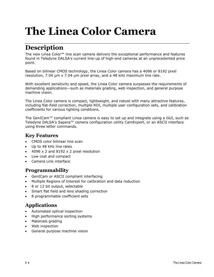
Description The new Linea Color™ line scan camera delivers the exceptional performance and features
found in Teledyne DALSA‘s current line-up of high-end cameras at an unprecedented price
point.
Based on bilinear CMOS technology, the Linea Color camera has a 4096 or 8192 pixel
resolution, 7.04 μm x 7.04 μm pixel array, and a 48 kHz maximum line rate.
With excellent sensitivity and speed, the Linea Color camera surpasses the requirements of
demanding applications—such as materials grading, web inspection, and general purpose
machine vision.
The Linea Color camera is compact, lightweight, and robust with many attractive features,
including flat-field correction, multiple ROI, multiple user configuration sets, and calibration
coefficients for various lighting conditions.
The GenICam™ compliant Linea camera is easy to set up and integrate using a GUI, such as
Teledyne DALSA‘s Sapera™ camera configuration utility CamExpert, or an ASCII interface
using three letter commands.
Key Features CMOS color bilinear line scan
Up to 48 kHz line rates
4096 x 2 and 8192 x 2 pixel resolution
Low cost and compact
Camera Link interface
Programmability GenICam or ASCII compliant interfacing
Multiple Regions of Interest for calibration and data reduction
8 or 12 bit output, selectable
Smart flat field and lens shading correction
8 programmable coefficient sets
Applications Automated optical inspection
High performance sorting systems
Materials grading
Web inspection
General purpose machine vision
The Linea Color Camera 7
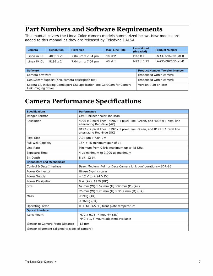
Part Numbers and Software Requirements This manual covers the Linea Color camera models summarized below. New models are
added to this manual as they are released by Teledyne DALSA.
Camera Resolution Pixel size Max. Line Rate Lens Mount (threaded)
Product Number
Linea 4k CL 4096 x 2 7.04 µm x 7.04 µm 48 kHz M42 x 1 LA-CC-04K05B-xx-R
Linea 8k CL 8192 x 2 7.04 µm x 7.04 µm 48 kHz M72 x 0.75 LA-CC-08K05B-xx-R
Software Product Number / Version Number
Camera firmware Embedded within camera
GenICam™ support (XML camera description file) Embedded within camera
Sapera LT, including CamExpert GUI application and GenICam for Camera Link imaging driver
Version 7.30 or later
Camera Performance Specifications
Specifications Performance
Imager Format CMOS bilinear color line scan
Resolution 4096 x 2 pixel lines: 4096 x 1 pixel line Green, and 4096 x 1 pixel line alternating Red-Blue (4K)
8192 x 2 pixel lines: 8192 x 1 pixel line Green, and 8192 x 1 pixel line alternating Red-Blue (8K)
Pixel Size 7.04 µm x 7.04 µm
Full Well Capacity 15K e- @ minimum gain of 1x
Line Rate Minimum from 0 kHz maximum up to 48 KHz.
Exposure Time 4 µs minimum to 3,000 µs maximum
Bit Depth 8 bit, 12 bit
Connectors and Mechanicals
Control & Data Interface Base, Medium, Full, or Deca Camera Link configurations—SDR-26
Power Connector Hirose 6-pin circular
Power Supply + 12 V to + 24 V DC
Power Dissipation 8 W (4K), 11 W (8K)
Size 62 mm (W) x 62 mm (H) x37 mm (D) (4K)
76 mm (W) x 76 mm (H) x 36.7 mm (D) (8K)
Mass <190g (4K)
< 360 g (8K)
Operating Temp 0 °C to +65 °C, front plate temperature
Optical Interface
Lens Mount M72 x 0.75, F-mount* (8K)
M42 x 1, F mount adapters available
Sensor to Camera Front Distance 12 mm
Sensor Alignment (aligned to sides of camera)
8 The Linea Color Camera
Flatness
y (parallelism)
x
y
z
z
50 µm
0.08° or 81 µm
± 300 µm
± 300 µm
± 300 µm
± 0.3°
Compliance
Regulatory Compliance CE and RoHS, GenICam
* F-mount lenses are optimized for a maximum image circle of 43.2 mm. The camera sensor is 57.67mm long. Using an F-mount lens will generate a good image for the center 6008 pixels. However, pixels beyond this range may suffer from optical distortion caused by the lens. If an application requires the use of an F-mount lens with cameras, contact Customer Support for additional details regarding the use of F-mount lenses and for access to a suitable F-mount-to-M72 adapter.
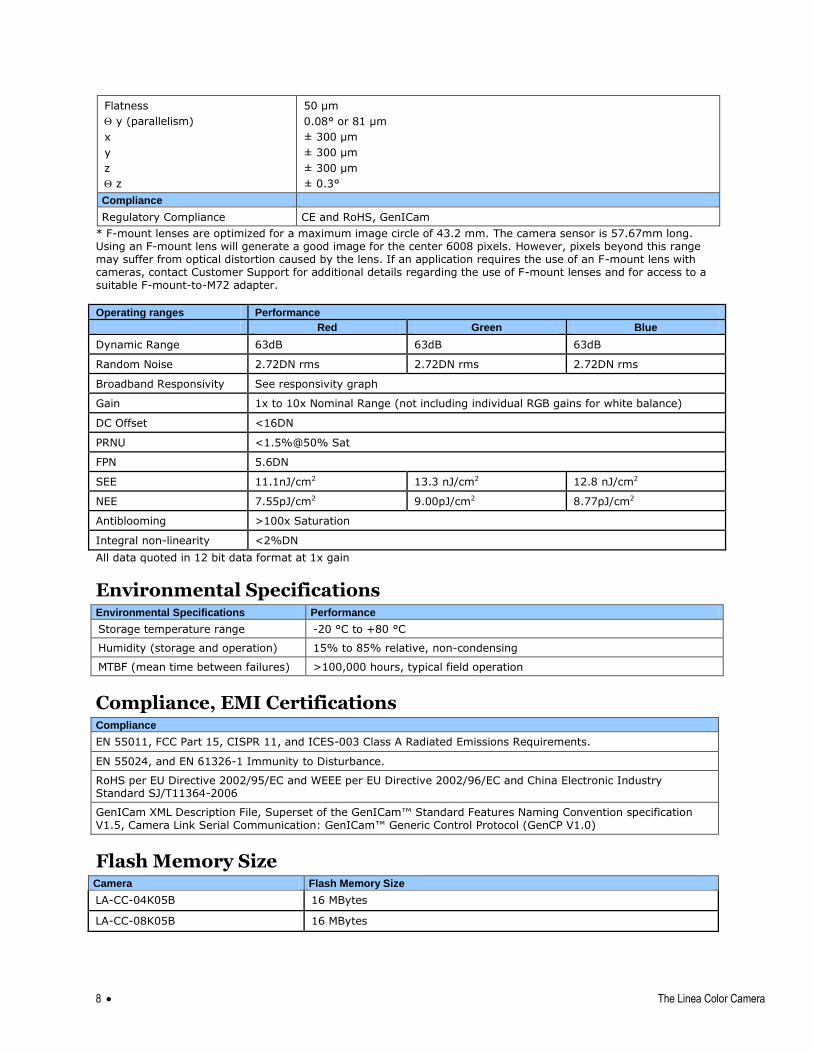
Operating ranges Performance
Red Green Blue
Dynamic Range 63dB 63dB 63dB
Random Noise 2.72DN rms 2.72DN rms 2.72DN rms
Broadband Responsivity See responsivity graph
Gain 1x to 10x Nominal Range (not including individual RGB gains for white balance)
DC Offset <16DN
PRNU <1.5%@50% Sat
FPN 5.6DN
SEE 11.1nJ/cm2 13.3 nJ/cm2 12.8 nJ/cm2
NEE 7.55pJ/cm2 9.00pJ/cm2 8.77pJ/cm2
Antiblooming >100x Saturation
Integral non-linearity <2%DN All data quoted in 12 bit data format at 1x gain
Environmental Specifications Environmental Specifications Performance
Storage temperature range -20 °C to +80 °C
Humidity (storage and operation) 15% to 85% relative, non-condensing
MTBF (mean time between failures) >100,000 hours, typical field operation
Compliance, EMI Certifications Compliance
EN 55011, FCC Part 15, CISPR 11, and ICES-003 Class A Radiated Emissions Requirements.
EN 55024, and EN 61326-1 Immunity to Disturbance.
RoHS per EU Directive 2002/95/EC and WEEE per EU Directive 2002/96/EC and China Electronic Industry Standard SJ/T11364-2006
GenICam XML Description File, Superset of the GenICam™ Standard Features Naming Convention specification V1.5, Camera Link Serial Communication: GenICam™ Generic Control Protocol (GenCP V1.0)
Flash Memory Size Camera Flash Memory Size
LA-CC-04K05B 16 MBytes
LA-CC-08K05B 16 MBytes
The Linea Color Camera 9
Supported Industry Standards
GenICam™ The camera is GenICam compliant. They implement a superset of the GenICam™ Standard
Features Naming Convention specification V1.5. This description takes the form of an XML
device description file respecting the syntax defined by the GenAPI module of the
GenICam™ specification. The camera uses the GenICam™ Generic Control Protocol (GenCP
V1.0) to communicate over the Camera Link serial port. For more information see
www.genicam.org.
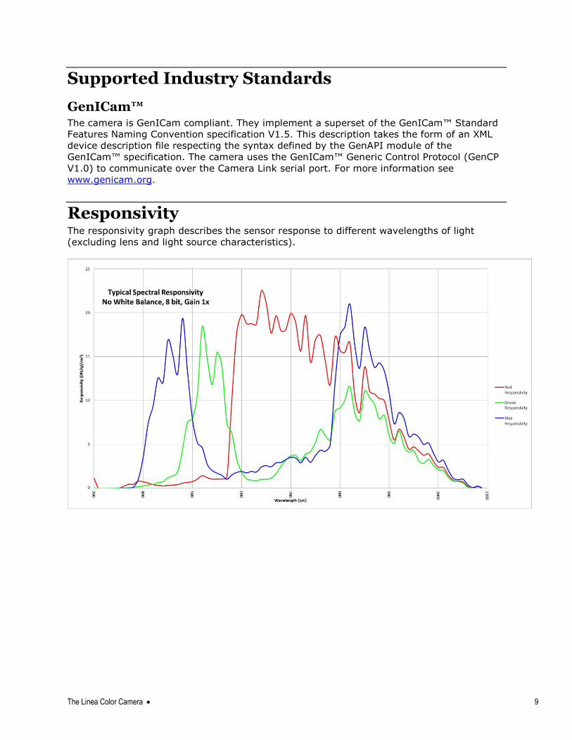
Responsivity The responsivity graph describes the sensor response to different wavelengths of light
(excluding lens and light source characteristics).
10 The Linea Color Camera
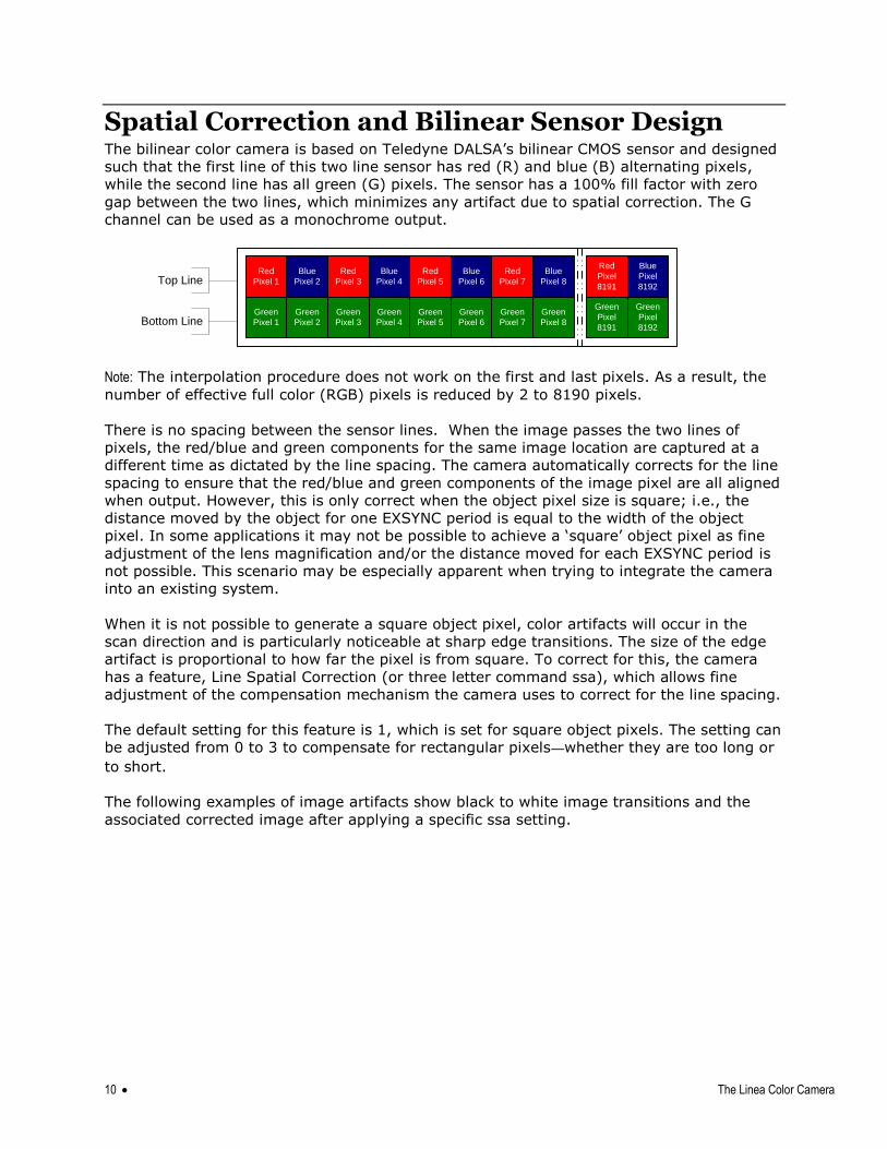
Spatial Correction and Bilinear Sensor Design The bilinear color camera is based on Teledyne DALSA‘s bilinear CMOS sensor and designed
such that the first line of this two line sensor has red (R) and blue (B) alternating pixels,
while the second line has all green (G) pixels. The sensor has a 100% fill factor with zero
gap between the two lines, which minimizes any artifact due to spatial correction. The G
channel can be used as a monochrome output.
Note: The interpolation procedure does not work on the first and last pixels. As a result, the
number of effective full color (RGB) pixels is reduced by 2 to 8190 pixels.
There is no spacing between the sensor lines. When the image passes the two lines of
pixels, the red/blue and green components for the same image location are captured at a
different time as dictated by the line spacing. The camera automatically corrects for the line
spacing to ensure that the red/blue and green components of the image pixel are all aligned
when output. However, this is only correct when the object pixel size is square; i.e., the
distance moved by the object for one EXSYNC period is equal to the width of the object
pixel. In some applications it may not be possible to achieve a ‗square‘ object pixel as fine
adjustment of the lens magnification and/or the distance moved for each EXSYNC period is
not possible. This scenario may be especially apparent when trying to integrate the camera
into an existing system.
When it is not possible to generate a square object pixel, color artifacts will occur in the
scan direction and is particularly noticeable at sharp edge transitions. The size of the edge
artifact is proportional to how far the pixel is from square. To correct for this, the camera
has a feature, Line Spatial Correction (or three letter command ssa), which allows fine
adjustment of the compensation mechanism the camera uses to correct for the line spacing.
The default setting for this feature is 1, which is set for square object pixels. The setting can
be adjusted from 0 to 3 to compensate for rectangular pixels—whether they are too long or
to short.
The following examples of image artifacts show black to white image transitions and the
associated corrected image after applying a specific ssa setting.
Red
Pixel 1
Green
Pixel 1
Blue
Pixel 2
Green
Pixel 2
Red
Pixel 3
Green
Pixel 3
Blue
Pixel 4
Green
Pixel 4
Red
Pixel 5
Green
Pixel 5
Blue
Pixel 6
Green
Pixel 6
Red
Pixel 7
Green
Pixel 7
Blue
Pixel 8
Green
Pixel 8
Red
Pixel
8191
Green
Pixel
8191
Blue
Pixel
8192
Green
Pixel
8192
Top Line
Bottom Line
The Linea Color Camera 11
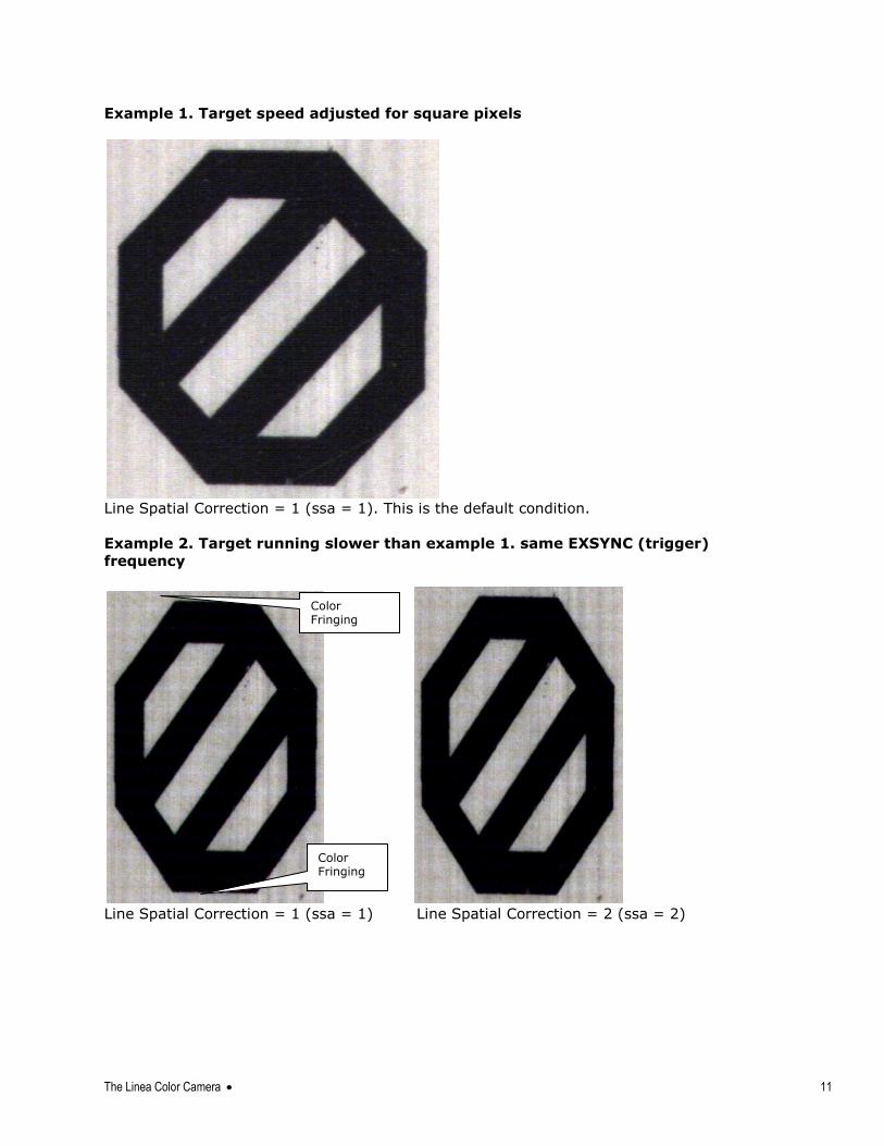
Example 1. Target speed adjusted for square pixels
Line Spatial Correction = 1 (ssa = 1). This is the default condition.
Example 2. Target running slower than example 1. same EXSYNC (trigger)
frequency
Line Spatial Correction = 1 (ssa = 1) Line Spatial Correction = 2 (ssa = 2)
Color Fringing
Color Fringing
12 The Linea Color Camera
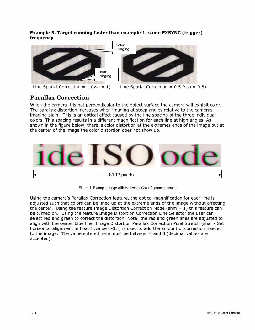
Example 3. Target running faster than example 1. same EXSYNC (trigger)
frequency
Line Spatial Correction = 1 (ssa = 1) Line Spatial Correction = 0.5 (ssa = 0.5)
Parallax Correction When the camera it is not perpendicular to the object surface the camera will exhibit color.
The parallax distortion increases when imaging at steep angles relative to the cameras
imaging plain. This is an optical effect caused by the line spacing of the three individual
colors. This spacing results in a different magnification for each line at high angles. As
shown in the figure below, there is color distortion at the extremes ends of the image but at
the center of the image the color distortion does not show up.
8192 pixels
Figure 1: Example Image with Horizontal Color Alignment Issues
Using the camera‘s Parallax Correction feature, the optical magnification for each line is
adjusted such that colors can be lined up at the extreme ends of the image without affecting
the center. Using the feature Image Distortion Correction Mode (shm = 1) this feature can
be turned on. Using the feature Image Distortion Correction Line Selector the user can
select red and green to correct the distortion. Note: the red and green lines are adjusted to
align with the center blue line. Image Distortion Parallax Correction Pixel Stretch (sha - Set
horizontal alignment in float f<value 0-3>) is used to add the amount of correction needed
to the image. The value entered here must be between 0 and 3 (decimal values are
accepted).
Color Fringing
Color Fringing
The Linea Color Camera 13
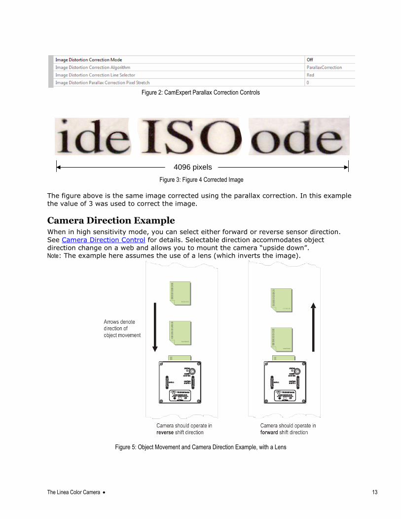
Figure 2: CamExpert Parallax Correction Controls
4096 pixels
Figure 3: Figure 4 Corrected Image
The figure above is the same image corrected using the parallax correction. In this example
the value of 3 was used to correct the image.
Camera Direction Example When in high sensitivity mode, you can select either forward or reverse sensor direction.
See Camera Direction Control for details. Selectable direction accommodates object
direction change on a web and allows you to mount the camera ―upside down‖. Note: The example here assumes the use of a lens (which inverts the image).
Figure 5: Object Movement and Camera Direction Example, with a Lens
14 The Linea Color Camera
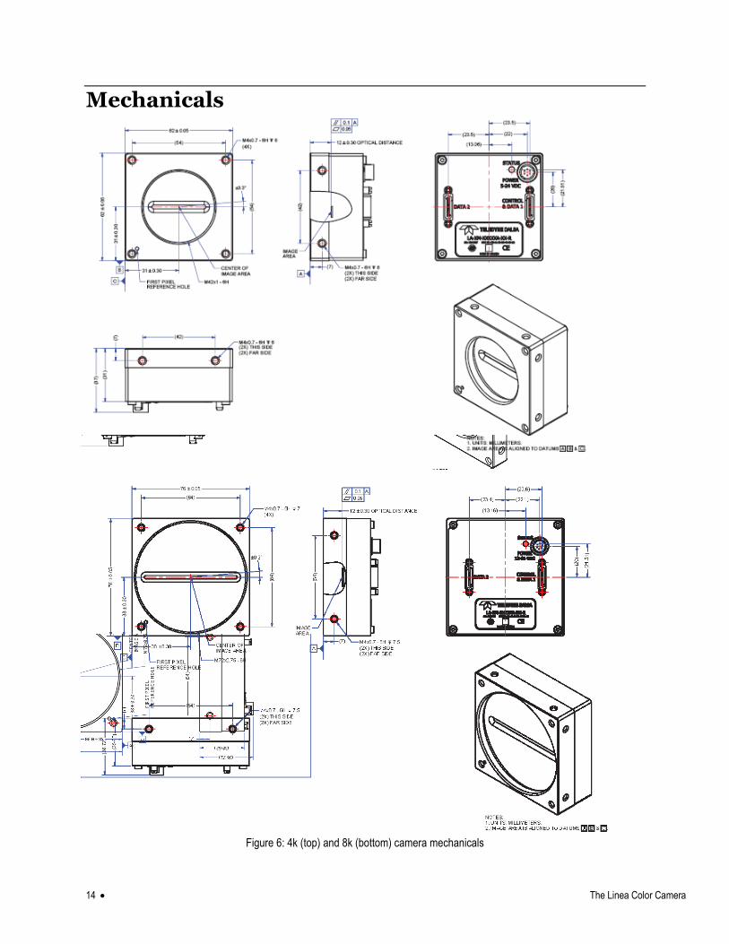
Mechanicals
Figure 6: 4k (top) and 8k (bottom) camera mechanicals
Quick, Simple Steps to Acquire an Image 15
Quick, Simple Steps to Acquire an Image For users who are familiar with Camera Link cameras, have a basic understanding of their
imaging requirements, and who are primarily interested in evaluating the camera, an
overview of the steps required to get this camera operational and acquiring images quickly
can be found in Appendix C: Quick Setup and Image Acquisition.
Software and Hardware Setup
Recommended System Requirements To achieve best system performance, the following minimum requirements are
recommended:
High bandwidth Camera Link frame grabber. We recommend Teledyne DALSA‘s Xtium™-
CL MX4 frame grabbers. More information can be found here.
Operating system: Windows XP 32-bit.
Setup Steps: Overview Take the following steps in order to setup and run your camera system. They are described
briefly below and in more detail in the sections that follow.
Step 1: Install and Configure Frame Grabber and Software (including GUI) If your host computer does not have a full Camera Link frame grabber then you will need to
install one. Follow the manufacturer‘s installation instructions.
A GenICam™ compliant XML device description file is embedded within the camera firmware
allowing GenICam™ compliant application to know the camera‘s capabilities immediately
after connection. Installing SaperaLT gives you access to the CamExpert GUI, a GenICam™
compliant application.
Step 2: Connect Camera Link and Power Cables
Connect the Camera Link cable(s) from the camera to the computer.
Connect a power cable from the camera to a +12 VDC to +24 VDC power supply.
WARNING! Grounding Instructions
Static electricity can damage electronic components. It‘s critical that you
discharge any static electrical charge by touching a grounded surface, such as
the metal computer chassis, before handling the camera hardware.
16 Software and Hardware Setup
Note: the use of cables types and lengths other than those specified may result
in increased emission or decreased immunity and performance of the camera.
Step 3: Establish communicating with the camera Start the GUI and establish communication with the camera. Refer to Step 2: Connect
Camera Link and Power Cables for a description on communicating with the camera.
ASCII Commands As an alternative to the CamExpert (or equivalent) GUI, you can communicate with this
camera using ASCII-based commands. A complete list of the commands can be found in the
appendix: ASCII User Command Reference.
Step 4: Operate the Camera
At this point you will be ready to start operating the camera in order to acquire images, set
camera functions, and save settings.
Step 1: Install and configure the frame grabber, and software (including GUI)
Install Frame Grabber Install a Full configuration Camera Link frame grabber according to the manufacturer‘s
description.
Install Sapera LT and CamExpert GUI
Communicate with the camera using a Camera Link-compliant interface. We recommend
you use CamExpert. CamExpert is the camera interfacing tool supported by the Sapera
library and comes bundled with Sapera LT. Using CamExpert is the simplest and quickest
way to send commands to and receive information from the camera.
Camera Link Environment These cameras implement the Camera link specification, which defines the device
capabilities.
The Camera link XML device description file is embedded within the camera firmware
allowing Camera link-compliant applications to recognize the cameras‘ capabilities
immediately after connection.
Software and Hardware Setup 17
Step 2: Connect Data, Trigger, and Power Cables Note: the use of cables types and lengths other than those specified may result in increased
emission or decreased immunity and performance of the camera.
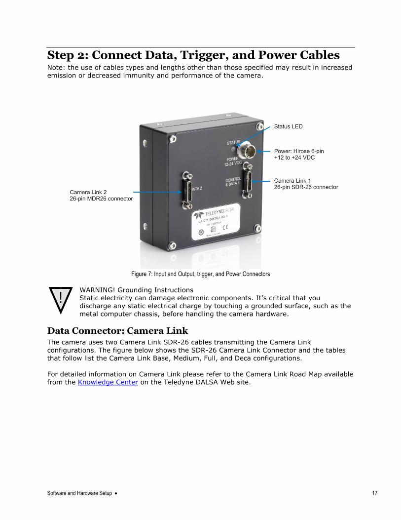
Figure 7: Input and Output, trigger, and Power Connectors
WARNING! Grounding Instructions
Static electricity can damage electronic components. It‘s critical that you
discharge any static electrical charge by touching a grounded surface, such as the
metal computer chassis, before handling the camera hardware.
Data Connector: Camera Link The camera uses two Camera Link SDR-26 cables transmitting the Camera Link
configurations. The figure below shows the SDR-26 Camera Link Connector and the tables
that follow list the Camera Link Base, Medium, Full, and Deca configurations.
For detailed information on Camera Link please refer to the Camera Link Road Map available
from the Knowledge Center on the Teledyne DALSA Web site.
!
18 Software and Hardware Setup
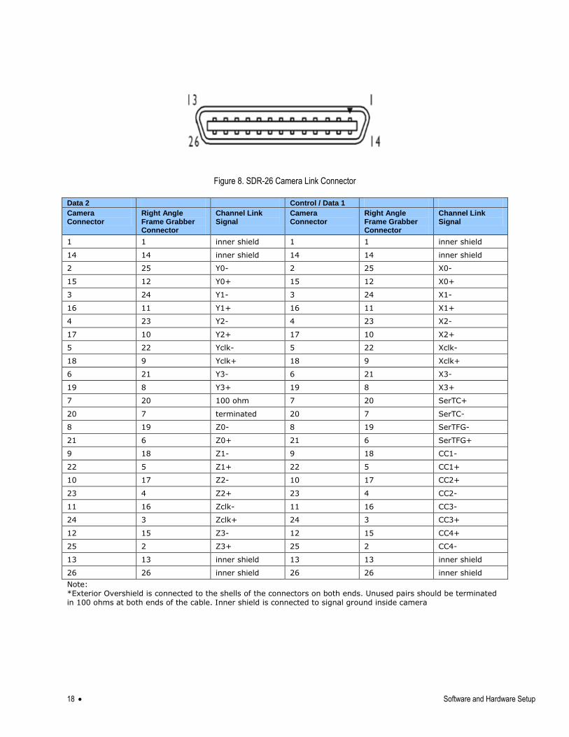
Figure 8. SDR-26 Camera Link Connector
Data 2 Control / Data 1
Camera Connector
Right Angle Frame Grabber Connector
Channel Link Signal
Camera Connector
Right Angle Frame Grabber Connector
Channel Link Signal
1 1 inner shield 1 1 inner shield
14 14 inner shield 14 14 inner shield
2 25 Y0- 2 25 X0-
15 12 Y0+ 15 12 X0+
3 24 Y1- 3 24 X1-
16 11 Y1+ 16 11 X1+
4 23 Y2- 4 23 X2-
17 10 Y2+ 17 10 X2+
5 22 Yclk- 5 22 Xclk-
18 9 Yclk+ 18 9 Xclk+
6 21 Y3- 6 21 X3-
19 8 Y3+ 19 8 X3+
7 20 100 ohm 7 20 SerTC+
20 7 terminated 20 7 SerTC-
8 19 Z0- 8 19 SerTFG-
21 6 Z0+ 21 6 SerTFG+
9 18 Z1- 9 18 CC1-
22 5 Z1+ 22 5 CC1+
10 17 Z2- 10 17 CC2+
23 4 Z2+ 23 4 CC2-
11 16 Zclk- 11 16 CC3-
24 3 Zclk+ 24 3 CC3+
12 15 Z3- 12 15 CC4+
25 2 Z3+ 25 2 CC4-
13 13 inner shield 13 13 inner shield
26 26 inner shield 26 26 inner shield
Note: *Exterior Overshield is connected to the shells of the connectors on both ends. Unused pairs should be terminated in 100 ohms at both ends of the cable. Inner shield is connected to signal ground inside camera
Software and Hardware Setup 19
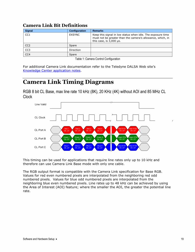
Camera Link Bit Definitions Signal Configuration Remarks
CC1 EXSYNC Keep this signal in low status when idle. The exposure time
must not be greater than the camera‘s allowance, which, in this case, is 3,000 µs.
CC2 Spare
CC3 Direction
CC4 Spare
Table 1: Camera Control Configuration
For additional Camera Link documentation refer to the Teledyne DALSA Web site‘s
Knowledge Center application notes.
Camera Link Timing Diagrams
RGB 8 bit CL Base, max line rate 10 kHz (8K), 20 KHz (4K) without AOI and 85 MHz CL Clock
This timing can be used for applications that require line rates only up to 10 kHz and
therefore can use Camera Link Base mode with only one cable.
The RGB output format is compatible with the Camera Link specification for Base RGB.
Values for red even numbered pixels are interpolated from the neighboring red odd
numbered pixels. Values for blue odd numbered pixels are interpolated from the
neighboring blue even numbered pixels. Line rates up to 48 kHz can be achieved by using
the Area of Interest (AOI) feature; where the smaller the AOI, the greater the potential line
rate.
20 Software and Hardware Setup
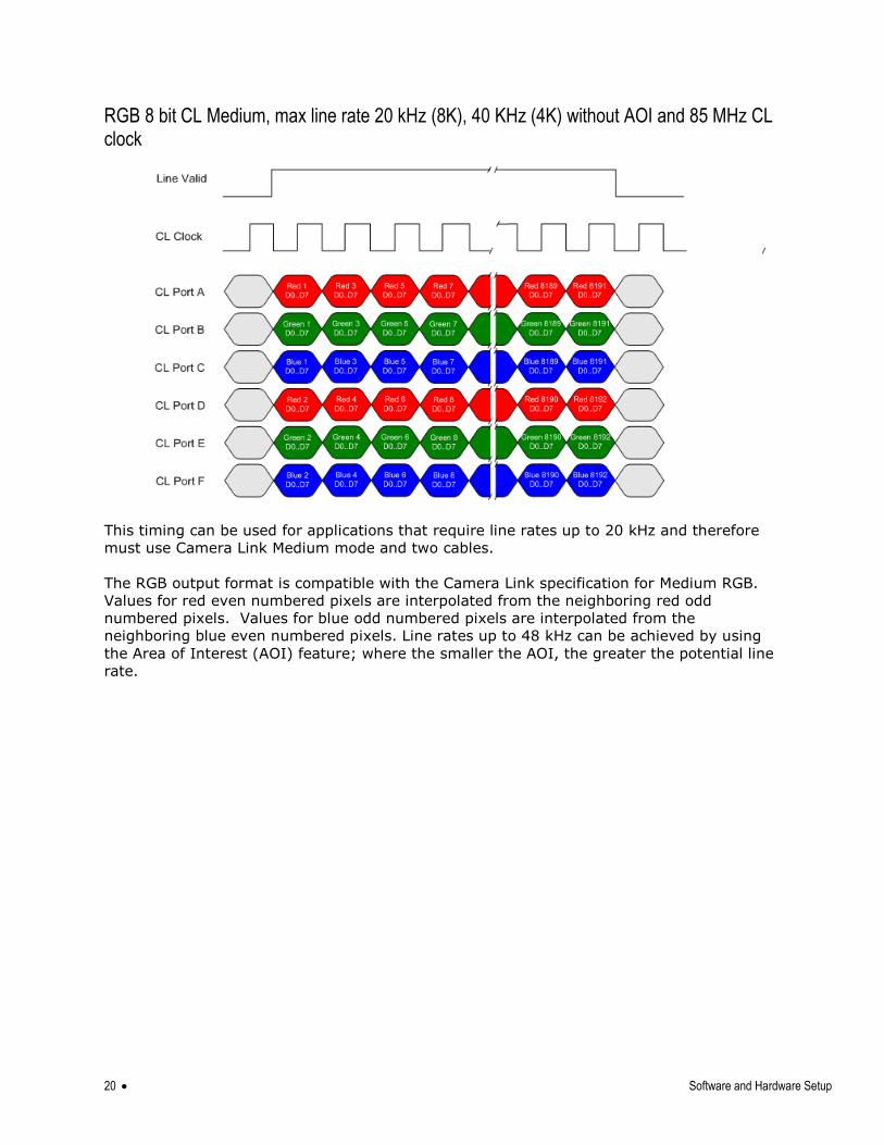
RGB 8 bit CL Medium, max line rate 20 kHz (8K), 40 KHz (4K) without AOI and 85 MHz CL clock
This timing can be used for applications that require line rates up to 20 kHz and therefore
must use Camera Link Medium mode and two cables.
The RGB output format is compatible with the Camera Link specification for Medium RGB.
Values for red even numbered pixels are interpolated from the neighboring red odd
numbered pixels. Values for blue odd numbered pixels are interpolated from the
neighboring blue even numbered pixels. Line rates up to 48 kHz can be achieved by using
the Area of Interest (AOI) feature; where the smaller the AOI, the greater the potential line
rate.
Software and Hardware Setup 21
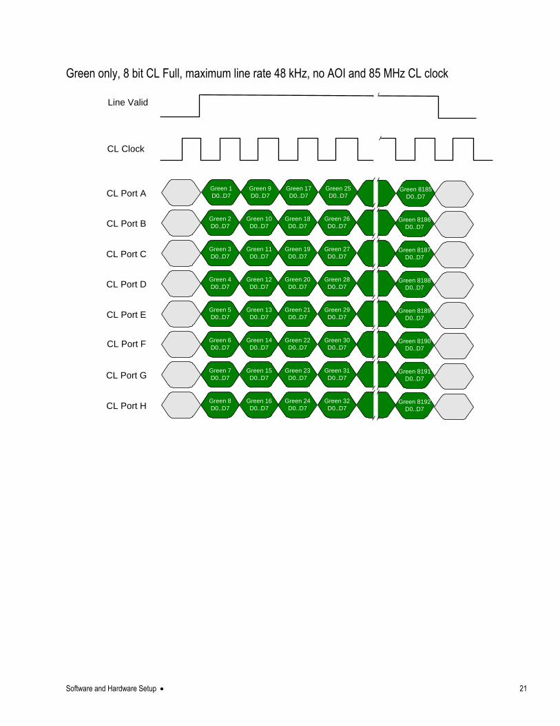
Green only, 8 bit CL Full, maximum line rate 48 kHz, no AOI and 85 MHz CL clock
Green 2
D0..D7
Green 3
D0..D7
Green 4
D0..D7
Green 5
D0..D7
Green 6
D0..D7
Green 7
D0..D7
CL Port A
CL Port B
CL Port C
CL Port D
CL Port E
CL Port F
CL Port G
CL Port H
CL Clock
Line Valid
Green 8
D0..D7
Green 1
D0..D7
Green 10
D0..D7
Green 11
D0..D7
Green 12
D0..D7
Green 13
D0..D7
Green 14
D0..D7
Green 15
D0..D7
Green 16
D0..D7
Green 9
D0..D7
Green 18
D0..D7
Green 19
D0..D7
Green 20
D0..D7
Green 21
D0..D7
Green 22
D0..D7
Green 23
D0..D7
Green 24
D0..D7
Green 17
D0..D7
Green 26
D0..D7
Green 27
D0..D7
Green 28
D0..D7
Green 29
D0..D7
Green 30
D0..D7
Green 31
D0..D7
Green 32
D0..D7
Green 25
D0..D7
Green 8186
D0..D7
Green 8187
D0..D7
Green 8188
D0..D7
Green 8189
D0..D7
Green 8190
D0..D7
Green 8191
D0..D7
Green 8192
D0..D7
Green 8185
D0..D7
22 Software and Hardware Setup
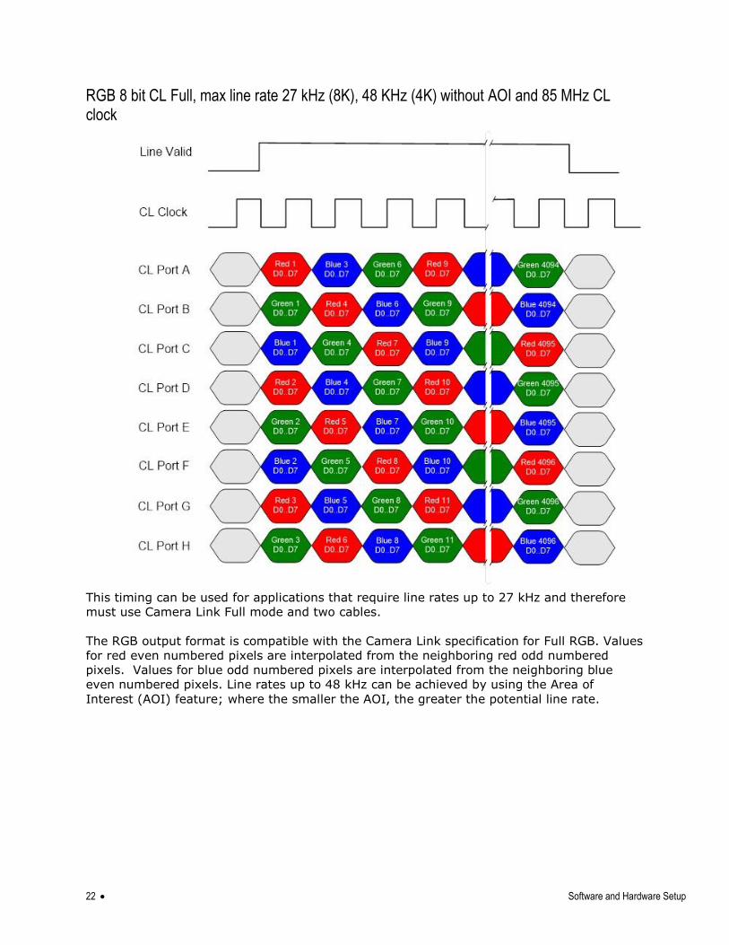
RGB 8 bit CL Full, max line rate 27 kHz (8K), 48 KHz (4K) without AOI and 85 MHz CL clock
This timing can be used for applications that require line rates up to 27 kHz and therefore
must use Camera Link Full mode and two cables.
The RGB output format is compatible with the Camera Link specification for Full RGB. Values
for red even numbered pixels are interpolated from the neighboring red odd numbered
pixels. Values for blue odd numbered pixels are interpolated from the neighboring blue
even numbered pixels. Line rates up to 48 kHz can be achieved by using the Area of
Interest (AOI) feature; where the smaller the AOI, the greater the potential line rate.
Software and Hardware Setup 23
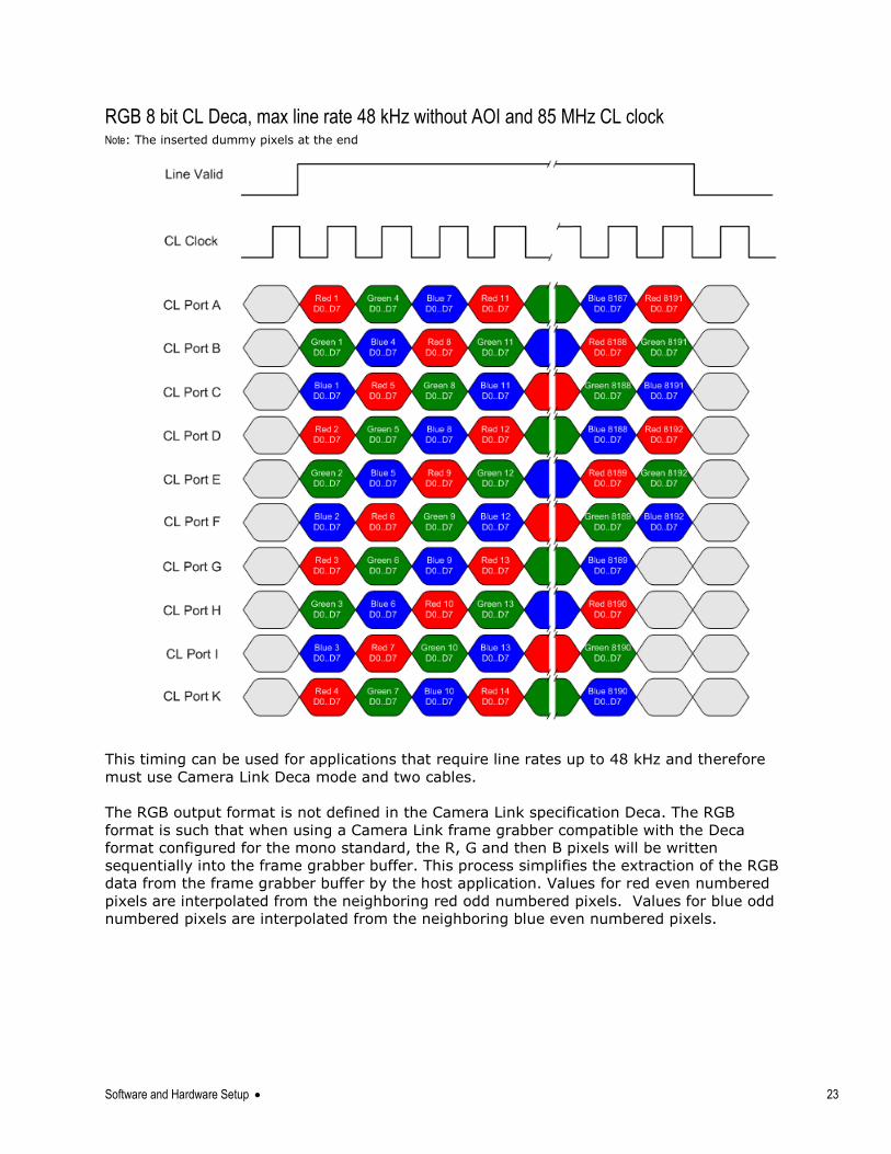
RGB 8 bit CL Deca, max line rate 48 kHz without AOI and 85 MHz CL clock Note: The inserted dummy pixels at the end
This timing can be used for applications that require line rates up to 48 kHz and therefore
must use Camera Link Deca mode and two cables.
The RGB output format is not defined in the Camera Link specification Deca. The RGB
format is such that when using a Camera Link frame grabber compatible with the Deca
format configured for the mono standard, the R, G and then B pixels will be written
sequentially into the frame grabber buffer. This process simplifies the extraction of the RGB
data from the frame grabber buffer by the host application. Values for red even numbered
pixels are interpolated from the neighboring red odd numbered pixels. Values for blue odd
numbered pixels are interpolated from the neighboring blue even numbered pixels.
24 Software and Hardware Setup
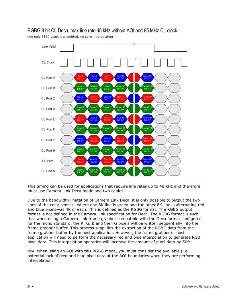
RGBG 8 bit CL Deca, max line rate 48 kHz without AOI and 85 MHz CL clock Note: only 8190 pixels transmitted, no color interpolation
This timing can be used for applications that require line rates up to 48 kHz and therefore
must use Camera Link Deca mode and two cables.
Due to the bandwidth limitation of Camera Link Deca, it is only possible to output the two
lines of the color sensor—where one 8K line is green and the other 8K line is alternating red
and blue pixels—as 4K of each. This is defined as the RGBG format. The RGBG output
format is not defined in the Camera Link specification for Deca. The RGBG format is such
that when using a Camera Link frame grabber compatible with the Deca format configured
for the mono standard, the R, G, B and then G pixels will be written sequentially into the
frame grabber buffer. This process simplifies the extraction of the RGBG data from the
frame grabber buffer by the host application. However, the frame grabber or host
application will need to perform the necessary red and blue interpolation to generate RGB
pixel data. This interpolation operation will increase the amount of pixel data by 50%.
Note: when using an AOI with this RGBG mode, you must consider the available (i.e.
potential lack of) red and blue pixel data at the AOI boundaries when they are performing
interpolation.
Software and Hardware Setup 25
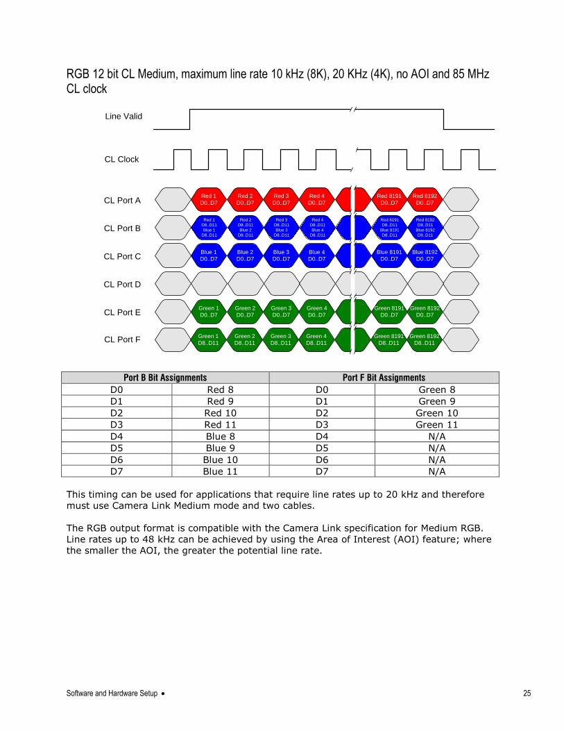
RGB 12 bit CL Medium, maximum line rate 10 kHz (8K), 20 KHz (4K), no AOI and 85 MHz CL clock
Port B Bit Assignments Port F Bit Assignments
D0 Red 8 D0 Green 8
D1 Red 9 D1 Green 9
D2 Red 10 D2 Green 10
D3 Red 11 D3 Green 11
D4 Blue 8 D4 N/A
D5 Blue 9 D5 N/A
D6 Blue 10 D6 N/A
D7 Blue 11 D7 N/A
This timing can be used for applications that require line rates up to 20 kHz and therefore
must use Camera Link Medium mode and two cables.
The RGB output format is compatible with the Camera Link specification for Medium RGB.
Line rates up to 48 kHz can be achieved by using the Area of Interest (AOI) feature; where
the smaller the AOI, the greater the potential line rate.
Red 1
D0..D7
Blue 1
D0..D7
Green 1
D0..D7
Red 1
D8..D11
Blue 1
D8..D11
Red 4
D0..D7
Red 8192
D0..D7
Blue 8192
D0..D7
Green 8192
D0..D7
Blue 4
D0..D7
Green 4
D0..D7
CL Port A
CL Port B
CL Port C
CL Port D
CL Port E
CL Port F
CL Clock
Line Valid
Green 2
D0..D7
Green 3
D0..D7
Green 8191
D0..D7
Green 1
D8..D11
Green 8192
D8..D11
Green 4
D8..D11
Green 2
D8..D11
Green 3
D8..D11
Green 8191
D8..D11
Red 2
D0..D7
Red 3
D0..D7
Red 8191
D0..D7
Blue 2
D0..D7
Blue 3
D0..D7
Blue 8191
D0..D7
Red 2
D8..D11
Blue 2
D8..D11
Red 3
D8..D11
Blue 3
D8..D11
Red 4
D8..D11
Blue 4
D8..D11
Red 8191
D8..D11
Blue 8191
D8..D11
Red 8192
D8..D11
Blue 8192
D8..D11
26 Software and Hardware Setup
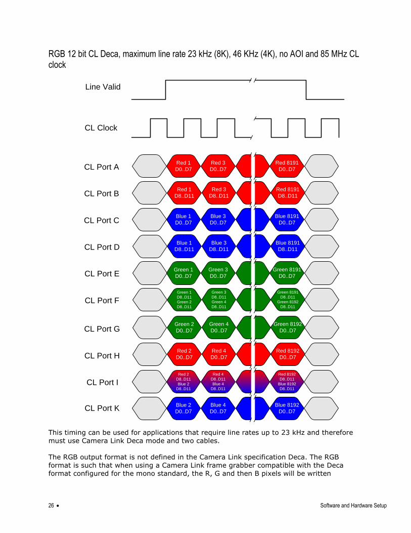
RGB 12 bit CL Deca, maximum line rate 23 kHz (8K), 46 KHz (4K), no AOI and 85 MHz CL clock
CL Port A
CL Port B
CL Port C
CL Clock
Line Valid
CL Port D
CL Port E
CL Port F
CL Port G
CL Port H
Red 1
D0..D7
Blue 1
D0..D7
Green 1
D0..D7
Red 1
D8..D11
CL Port I
CL Port K
Blue 1
D8..D11
Green 1
D8..D11
Green 2
D8..D11
Green 2
D0..D7
Blue 2
D0..D7
Red 2
D0..D7
Red 2
D8..D11
Blue 2
D8..D11
Red 3
D0..D7
Blue 3
D0..D7
Green 3
D0..D7
Red 3
D8..D11
Blue 3
D8..D11
Green 3
D8..D11
Green 4
D8..D11
Green 4
D0..D7
Blue 4
D0..D7
Red 4
D0..D7
Red 4
D8..D11
Blue 4
D8..D11
Red 8191
D0..D7
Blue 8191
D0..D7
Green 8191
D0..D7
Red 8191
D8..D11
Blue 8191
D8..D11
Green 8191
D8..D11
Green 8192
D8..D11
Green 8192
D0..D7
Blue 8192
D0..D7
Red 8192
D0..D7
Red 8192
D8..D11
Blue 8192
D8..D11
This timing can be used for applications that require line rates up to 23 kHz and therefore
must use Camera Link Deca mode and two cables.
The RGB output format is not defined in the Camera Link specification Deca. The RGB
format is such that when using a Camera Link frame grabber compatible with the Deca
format configured for the mono standard, the R, G and then B pixels will be written
Software and Hardware Setup 27
sequentially into the frame grabber buffer. This process simplifies the extraction of the RGB
data from the frame grabber buffer by the host application. Line rates up to 48 kHz can be
achieved by using the Area of Interest (AOI) feature; where the smaller the AOI, the
greater the potential line rate.
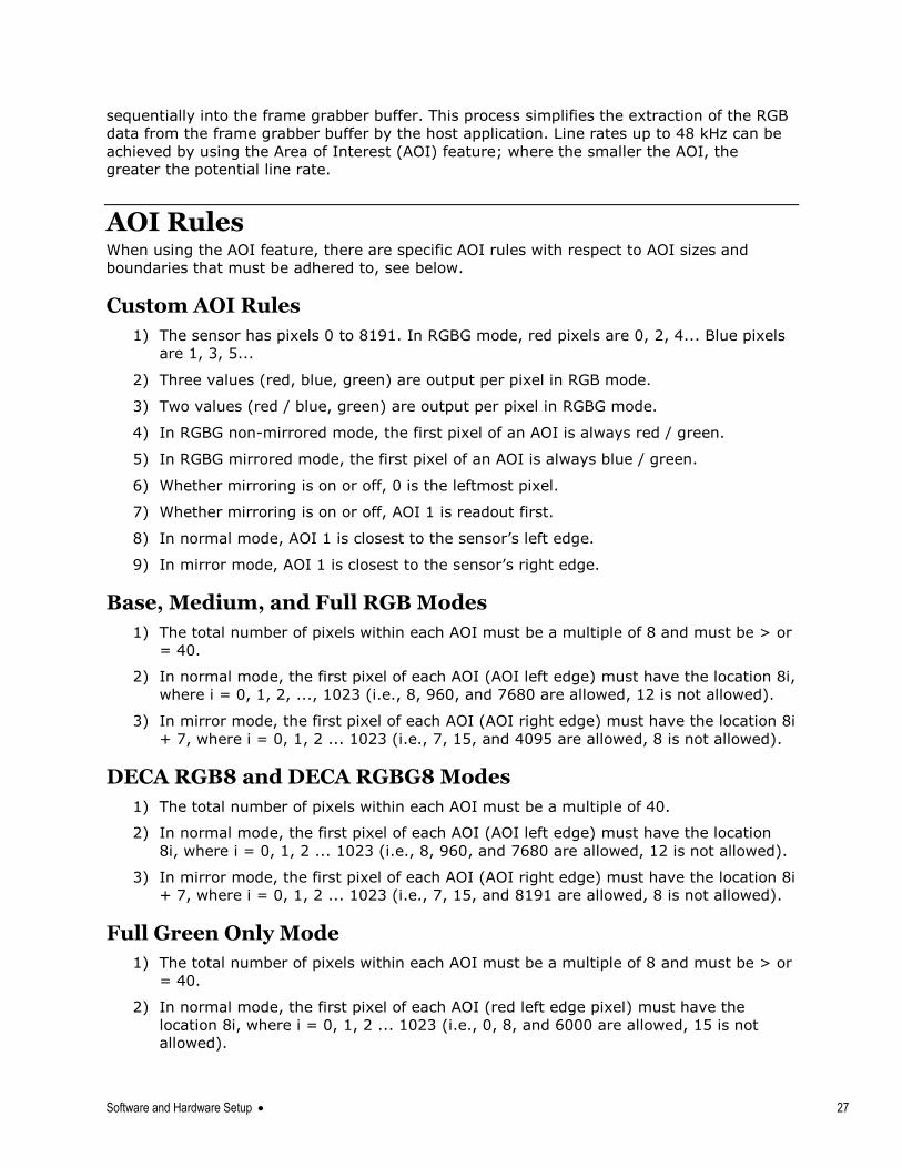
AOI Rules When using the AOI feature, there are specific AOI rules with respect to AOI sizes and
boundaries that must be adhered to, see below.
Custom AOI Rules
1) The sensor has pixels 0 to 8191. In RGBG mode, red pixels are 0, 2, 4... Blue pixels
are 1, 3, 5...
2) Three values (red, blue, green) are output per pixel in RGB mode.
3) Two values (red / blue, green) are output per pixel in RGBG mode.
4) In RGBG non-mirrored mode, the first pixel of an AOI is always red / green.
5) In RGBG mirrored mode, the first pixel of an AOI is always blue / green.
6) Whether mirroring is on or off, 0 is the leftmost pixel.
7) Whether mirroring is on or off, AOI 1 is readout first.
8) In normal mode, AOI 1 is closest to the sensor‘s left edge.
9) In mirror mode, AOI 1 is closest to the sensor‘s right edge.
Base, Medium, and Full RGB Modes
1) The total number of pixels within each AOI must be a multiple of 8 and must be > or
= 40.
2) In normal mode, the first pixel of each AOI (AOI left edge) must have the location 8i,
where i = 0, 1, 2, ..., 1023 (i.e., 8, 960, and 7680 are allowed, 12 is not allowed).
3) In mirror mode, the first pixel of each AOI (AOI right edge) must have the location 8i
+ 7, where i = 0, 1, 2 ... 1023 (i.e., 7, 15, and 4095 are allowed, 8 is not allowed).
DECA RGB8 and DECA RGBG8 Modes
1) The total number of pixels within each AOI must be a multiple of 40.
2) In normal mode, the first pixel of each AOI (AOI left edge) must have the location
8i, where i = 0, 1, 2 ... 1023 (i.e., 8, 960, and 7680 are allowed, 12 is not allowed).
3) In mirror mode, the first pixel of each AOI (AOI right edge) must have the location 8i
+ 7, where i = 0, 1, 2 ... 1023 (i.e., 7, 15, and 8191 are allowed, 8 is not allowed).
Full Green Only Mode
1) The total number of pixels within each AOI must be a multiple of 8 and must be > or
= 40.
2) In normal mode, the first pixel of each AOI (red left edge pixel) must have the
location 8i, where i = 0, 1, 2 ... 1023 (i.e., 0, 8, and 6000 are allowed, 15 is not
allowed).
28 Software and Hardware Setup
3) In mirror mode, the first pixel of each AOI (blue right edge pixel) must have the
location 8i + 7, where i = 2, 3, 4 ... 1023 (i.e., 31 and 8191 are allowed, 8 and 1024
are not allowed).
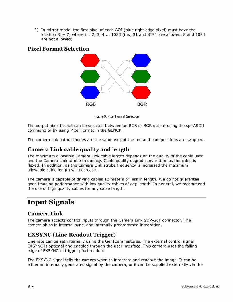
Pixel Format Selection
Figure 9. Pixel Format Selection
The output pixel format can be selected between an RGB or BGR output using the spf ASCII
command or by using Pixel Format in the GENCP.
The camera link output modes are the same except the red and blue positions are swapped.
Camera Link cable quality and length The maximum allowable Camera Link cable length depends on the quality of the cable used
and the Camera Link strobe frequency. Cable quality degrades over time as the cable is
flexed. In addition, as the Camera Link strobe frequency is increased the maximum
allowable cable length will decrease.
The camera is capable of driving cables 10 meters or less in length. We do not guarantee
good imaging performance with low quality cables of any length. In general, we recommend
the use of high quality cables for any cable length.
Input Signals
Camera Link The camera accepts control inputs through the Camera Link SDR-26F connector. The
camera ships in internal sync, and internally programmed integration.
EXSYNC (Line Readout Trigger) Line rate can be set internally using the GenICam features. The external control signal
EXSYNC is optional and enabled through the user interface. This camera uses the falling
edge of EXSYNC to trigger pixel readout.
The EXSYNC signal tells the camera when to integrate and readout the image. It can be
either an internally generated signal by the camera, or it can be supplied externally via the
RGB BGR
Software and Hardware Setup 29
serial interface. Depending upon the mode of operation the high time of the EXSYNC signal
can represent the integration period.
Note: The EXSYNC signal is measured at CC1 and will give a ―true‖ measurement (i.e.
within the measurement resolution of 25 ns) even though the camera will only trigger at a
maximum of 48 KHz.
Output Signals
Camera Link Clocking Signals These signals indicate when data is valid, allowing you to clock the data from the camera to
your acquisition system. These signals are part of the Camera Link configuration and you
should refer to the Camera Link Implementation Road Map, available at our Knowledge
Center, for the standard location of these signals.
Clocking Signal Indicates
LVAL (high) Outputting valid line
DVAL Not used
STROBE (rising edge) Valid data
FVAL Not used
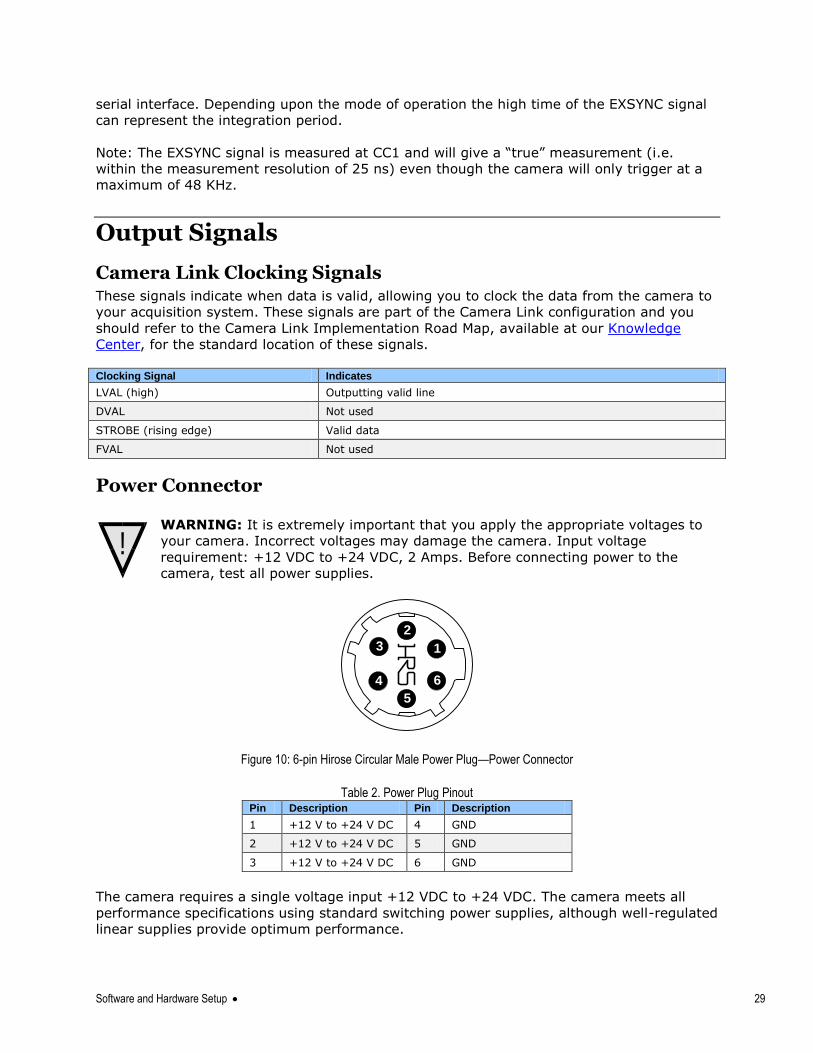
Power Connector
WARNING: It is extremely important that you apply the appropriate voltages to
your camera. Incorrect voltages may damage the camera. Input voltage
requirement: +12 VDC to +24 VDC, 2 Amps. Before connecting power to the
camera, test all power supplies.
1
6
5
4
3
2
Figure 10: 6-pin Hirose Circular Male Power Plug—Power Connector
Table 2. Power Plug Pinout Pin Description Pin Description
1 +12 V to +24 V DC 4 GND
2 +12 V to +24 V DC 5 GND
3 +12 V to +24 V DC 6 GND
The camera requires a single voltage input +12 VDC to +24 VDC. The camera meets all
performance specifications using standard switching power supplies, although well-regulated
linear supplies provide optimum performance.
!
30 Software and Hardware Setup
!
WARNING: When setting up the camera’s power supplies follow these guidelines:
Apply the appropriate voltages.
Protect the camera with a 2 amp slow-blow fuse between the power supply and
the camera.
Do not use the shield on a multi-conductor cable for ground.
Keep leads as short as possible in order to reduce voltage drop.
Use high-quality supplies in order to minimize noise.
Note: If your power supply does not meet these requirements, then the camera
performance specifications are not guaranteed.
Camera Status LED The camera has one multicolor LED to provide a simple visible indication of camera state.
The table below summarizes the operating states of the camera and the corresponding LED
states. When more than one condition is active, the LED indicates the condition with the
highest priority.
LED State Definition
LED is off No power or hardware malfunction
Blinking Green Powering up or calibrating
Green Ready
Red Error. Check the built-in self test (BiST) register for the specific error
Step 3: Establish Communication with the Camera
Power on the camera Turn on the camera‘s power supply. You may have to wait while the camera readies itself
for operation. The camera must boot fully before it will be recognized by the GUI—the LED
shines green once the camera is ready.
Connect to the frame grabber 1. Start Sapera CamExpert (or equivalent Camera Link compliant interface) by double
clicking the desktop icon created during the software installation.
2. CamExpert will search for installed Sapera devices. In the Devices list area on the left
side, the connected frame grabber will be shown.
3. Select the frame grabber device by clicking on the name.
Connect to the camera 1. Start a new Sapera CamExpert application (or equivalent Camera Link compliant
interface) by double clicking the desktop icon created during the software installation.
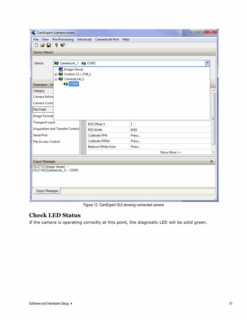
2. In the Devices list area on the left side, select the COM port below the Camera Link label.
Figure 11. CamExpert Icon, created during software installation
Software and Hardware Setup 31
Figure 12. CamExpert GUI showing connected camera
Check LED Status If the camera is operating correctly at this point, the diagnostic LED will be solid green.
32 Software and Hardware Setup
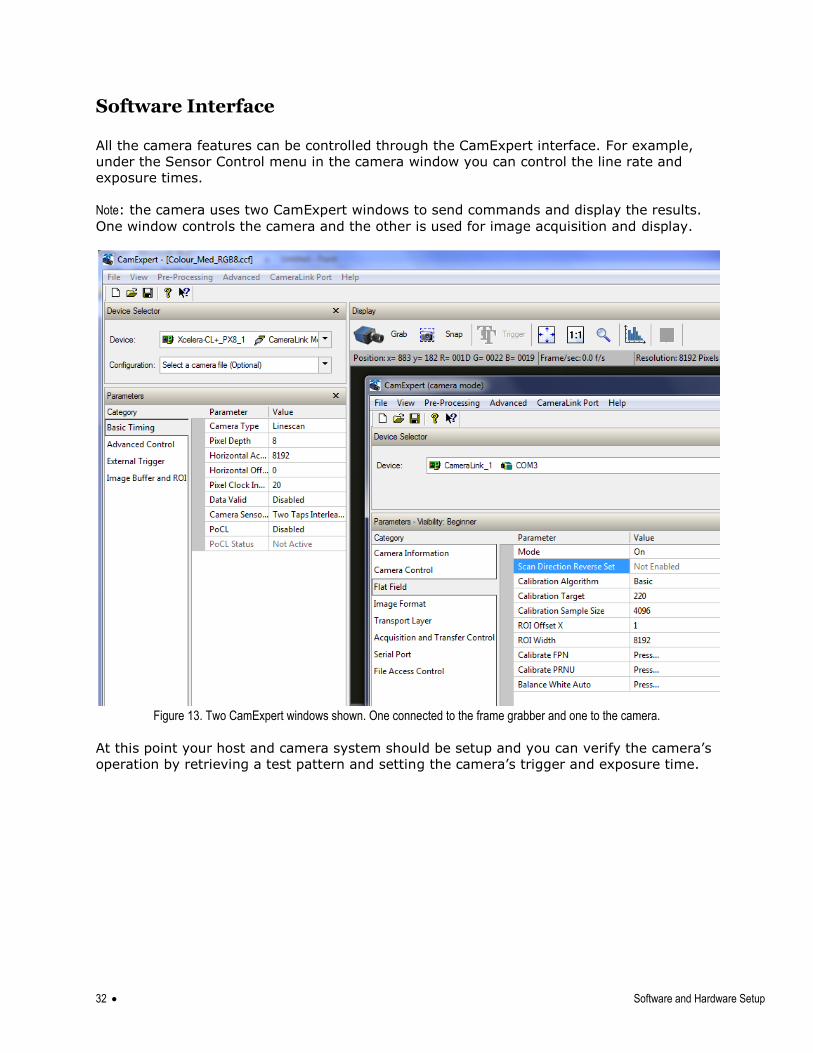
Software Interface
All the camera features can be controlled through the CamExpert interface. For example,
under the Sensor Control menu in the camera window you can control the line rate and
exposure times.
Note: the camera uses two CamExpert windows to send commands and display the results.
One window controls the camera and the other is used for image acquisition and display.
Figure 13. Two CamExpert windows shown. One connected to the frame grabber and one to the camera.
At this point your host and camera system should be setup and you can verify the camera‘s
operation by retrieving a test pattern and setting the camera‘s trigger and exposure time.
Software and Hardware Setup 33
Using Sapera CamExpert with Linea Cameras CamExpert is the camera interfacing tool supported by the Sapera library. When used with a
Teledyne DALSA camera, CamExpert allows a user to test all camera operating modes.
Additionally CamExpert saves the camera user settings configuration to the camera or saves
multiple configurations as individual camera parameter files on the host system (*.ccf).
CamExpert can also be used to upgrade the camera‘s software.
An important component of CamExpert is its live acquisition display window which allows
immediate verification of timing or control parameters without the need to run a separate
acquisition program.
For context sensitive help, click on the button then click on a camera configuration
parameter. A short description of the configuration parameter will be shown in a popup.
Click on the button to open the help file for more descriptive information on CamExpert.
The central section of CamExpert provides access to the camera features and parameters. Note: The availability of the features is dependent on the CamExpert user setting.
34 Software and Hardware Setup
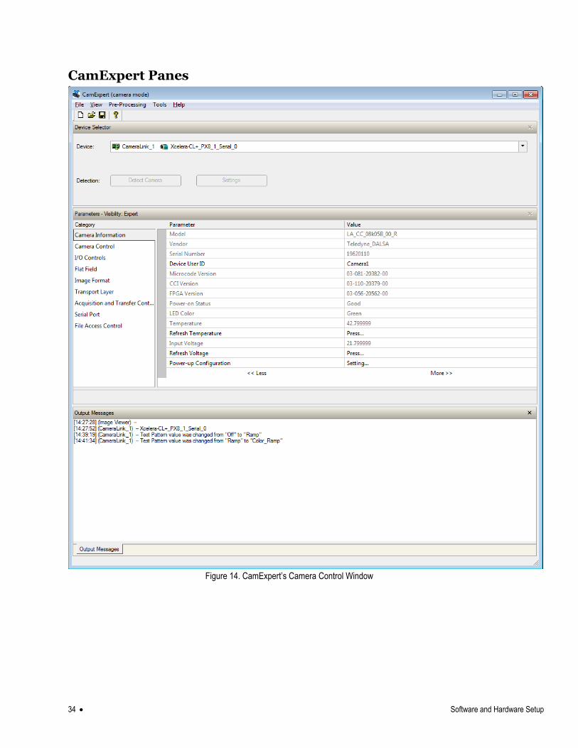
CamExpert Panes
Figure 14. CamExpert’s Camera Control Window
Software and Hardware Setup 35
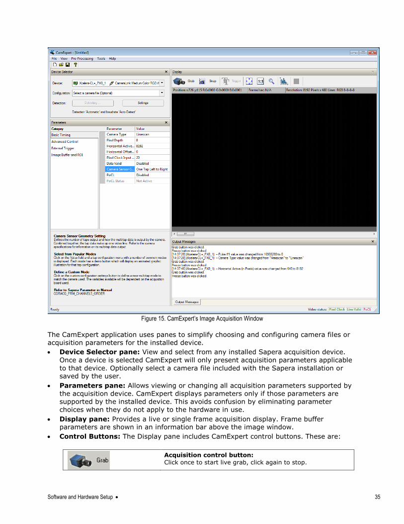
Figure 15. CamExpert’s Image Acquisition Window
The CamExpert application uses panes to simplify choosing and configuring camera files or
acquisition parameters for the installed device.
Device Selector pane: View and select from any installed Sapera acquisition device.
Once a device is selected CamExpert will only present acquisition parameters applicable
to that device. Optionally select a camera file included with the Sapera installation or saved by the user.
Parameters pane: Allows viewing or changing all acquisition parameters supported by
the acquisition device. CamExpert displays parameters only if those parameters are
supported by the installed device. This avoids confusion by eliminating parameter
choices when they do not apply to the hardware in use.
Display pane: Provides a live or single frame acquisition display. Frame buffer parameters are shown in an information bar above the image window.
Control Buttons: The Display pane includes CamExpert control buttons. These are:
Acquisition control button:
Click once to start live grab, click again to stop.
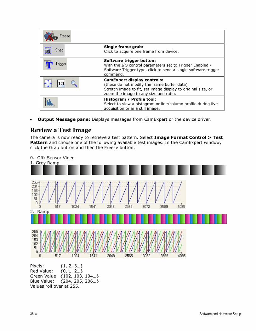
36 Software and Hardware Setup
Single frame grab:
Click to acquire one frame from device.
Software trigger button:
With the I/O control parameters set to Trigger Enabled / Software Trigger type, click to send a single software trigger command.
CamExpert display controls:
(these do not modify the frame buffer data) Stretch image to fit, set image display to original size, or zoom the image to any size and ratio.
Histogram / Profile tool: Select to view a histogram or line/column profile during live
acquisition or in a still image.
Output Message pane: Displays messages from CamExpert or the device driver.
Review a Test Image The camera is now ready to retrieve a test pattern. Select Image Format Control > Test
Pattern and choose one of the following available test images. In the CamExpert window,
click the Grab button and then the Freeze button.
0. Off: Sensor Video
1. Grey Ramp
2. Ramp
Pixels: {1, 2, 3…}
Red Value: {0, 1, 2…}
Green Value: {102, 103, 104…}
Blue Value: {204, 205, 206…}
Values roll over at 255.
4. Camera Operation 37
At this point you are ready to start operating the camera in order to acquire images, set
camera functions, and save settings.
4. Camera Operation
Factory Settings The camera ships and powers up for the first time with the following factory settings:
Camera Link Medium, 8 bit pixels, 85 MHz
Internal trigger, line rate 10 kHz
Internal exposure control, exposure time 50 µs
Flat field disabled
User coefficients set to 1x
Offset 0, System Gain 1x
Color correction disabled
Corrected using an 80 mm lens and a magnification of 0.8
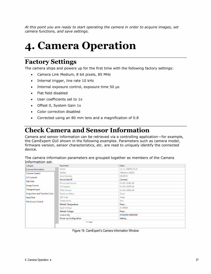
Check Camera and Sensor Information Camera and sensor information can be retrieved via a controlling application—for example,
the CamExpert GUI shown in the following examples. Parameters such as camera model,
firmware version, sensor characteristics, etc. are read to uniquely identify the connected
device.
The camera information parameters are grouped together as members of the Camera
Information set.
Figure 16. CamExpert’s Camera Information Window
38 4. Camera Operation
Verify Temperature and Voltage To determine the voltage and temperature at the camera, use the Refresh Voltage and
Refresh Temperature features found in the Camera Information set.
The temperature returned is the internal temperature in degrees Celsius. For proper
operation, this value should not exceed 75 °C. If the camera exceeds the designated
temperature it will stop imaging and the LED will turn red. Once you have diagnosed and
remedied the issue use the reset camera function.
The voltage displayed is the camera‘s input voltage. Note: The voltage measurement feature of the camera provides only approximate results
(typically within 10% and dependent on the voltage drop in the cable). The measurement
should not be used to set the applied voltage to the camera, but only used as a test to
isolate gross problems with the supply voltage.
Saving and Restoring Camera Settings The parameters used to select, load and save user sets are grouped together under the
Camera Information set of features. There are 8 user sets available and one factory set.
Camera Information
Parameter Choices
User Set Default Selector Select the camera parameters to load when the camera is reset or powered up as the Factory set, or as User Set 1 to 8.
Selecting the set from the list automatically saves it as the default set.
User Set Selector Select the Factory or User set to Save or Load.
-Factory Set
-User Set 1 to 8.
User Set Load Load the set specified by User Set Selector to the camera and make it the active / current set.
User Set Save Save the current set as selected user set.
Description of the Camera Settings The camera operates in one of three settings:
1. Current session.
2. User setting.
3. Factory setting (read-only).
4. Default setting.
The current settings can be saved (thereby becoming the user setting) using the User Set
Save parameter. A previously saved user setting (User Set 1 to 8) or the factory settings
can be restored using the User Set Selector and User Set Load parameters.
4. Camera Operation 39
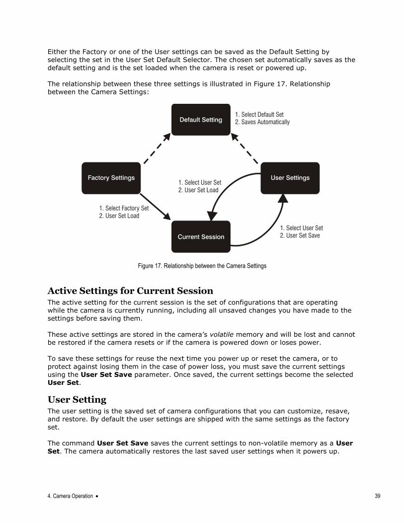
Either the Factory or one of the User settings can be saved as the Default Setting by
selecting the set in the User Set Default Selector. The chosen set automatically saves as the
default setting and is the set loaded when the camera is reset or powered up.
The relationship between these three settings is illustrated in Figure 17. Relationship
between the Camera Settings:
Figure 17. Relationship between the Camera Settings
Active Settings for Current Session The active setting for the current session is the set of configurations that are operating
while the camera is currently running, including all unsaved changes you have made to the
settings before saving them.
These active settings are stored in the camera‘s volatile memory and will be lost and cannot
be restored if the camera resets or if the camera is powered down or loses power.
To save these settings for reuse the next time you power up or reset the camera, or to
protect against losing them in the case of power loss, you must save the current settings
using the User Set Save parameter. Once saved, the current settings become the selected
User Set.
User Setting The user setting is the saved set of camera configurations that you can customize, resave,
and restore. By default the user settings are shipped with the same settings as the factory
set.
The command User Set Save saves the current settings to non-volatile memory as a User
Set. The camera automatically restores the last saved user settings when it powers up.
40 4. Camera Operation
To restore the last saved user settings, select the User Set parameter you want to restore
and then select the User Set Load parameter.
Factory Settings The factory setting is the camera settings that were shipped with the camera and which
loaded during the camera‘s first power-up. To load or restore the original factory settings, at
any time, select the Factory Setting parameter and then select the User Set Load
parameter.
Note: By default, the user settings are set to the factory settings.
Default Setting Either the Factory or one of the User settings can be used as the Default Setting by
selecting the set in the User Set Default Selector. The chosen set automatically becomes the
default setting and is the set loaded when the camera is reset of powered up.
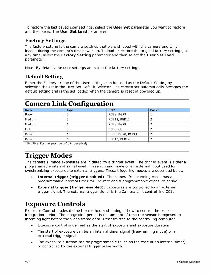
Camera Link Configuration Name Taps SPF* Cables
Base 3 RGB8, BGR8 1
Medium 3 RGB12, BGR12 2
Medium 6 RGB8, BGR8 2
Full 8 RGB8, G8 2
Deca 10 RBG8, BGR8, RGBG8 2
Deca 6 RGB12, BGR12 2
*Set Pixel Format (number of bits per pixel)
Trigger Modes The camera‘s image exposures are initiated by a trigger event. The trigger event is either a
programmable internal signal used in free running mode or an external input used for
synchronizing exposures to external triggers. These triggering modes are described below.
Internal trigger (trigger disabled): The camera free-running mode has a
programmable internal timer for line rate and a programmable exposure period.
External trigger (trigger enabled): Exposures are controlled by an external
trigger signal. The external trigger signal is the Camera Link control line CC1.
Exposure Controls Exposure Control modes define the method and timing of how to control the sensor
integration period. The integration period is the amount of time the sensor is exposed to
incoming light before the video frame data is transmitted to the controlling computer.
Exposure control is defined as the start of exposure and exposure duration.
The start of exposure can be an internal timer signal (free-running mode) or an
external trigger signal.
The exposure duration can be programmable (such as the case of an internal timer)
or controlled by the external trigger pulse width.
4. Camera Operation 41
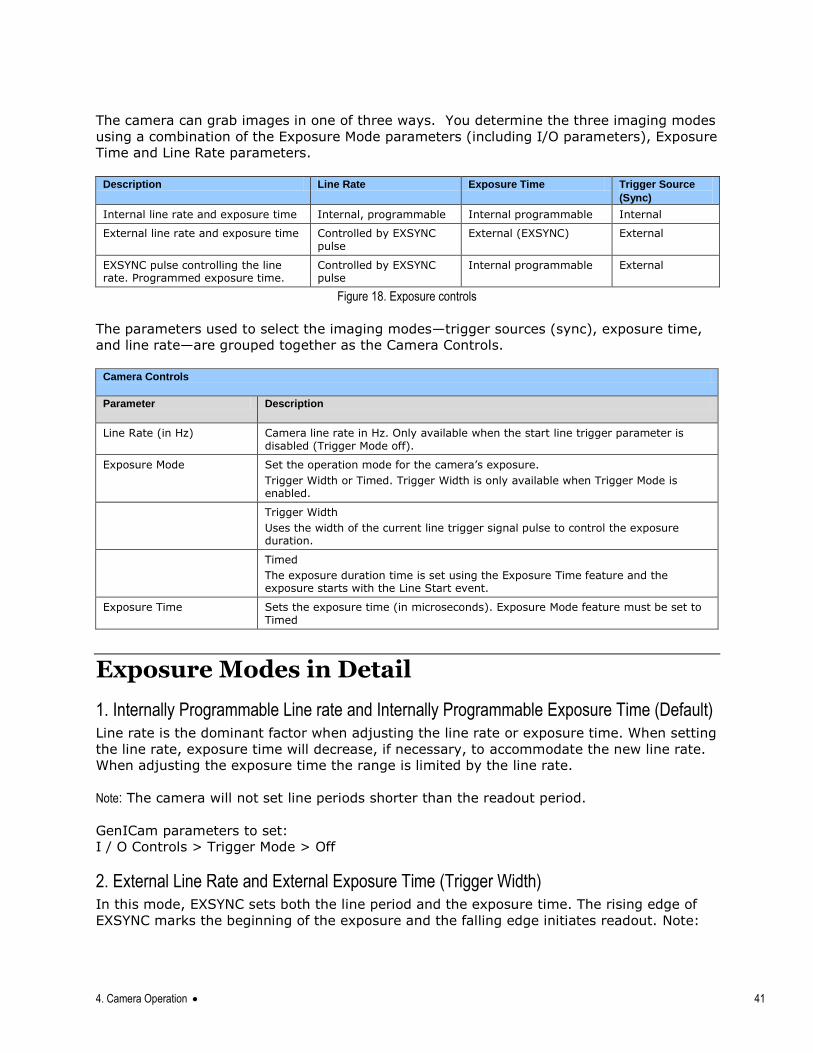
The camera can grab images in one of three ways. You determine the three imaging modes
using a combination of the Exposure Mode parameters (including I/O parameters), Exposure
Time and Line Rate parameters.
Description Line Rate Exposure Time Trigger Source
(Sync)
Internal line rate and exposure time Internal, programmable Internal programmable Internal
External line rate and exposure time Controlled by EXSYNC pulse
External (EXSYNC) External
EXSYNC pulse controlling the line rate. Programmed exposure time.
Controlled by EXSYNC pulse
Internal programmable External
Figure 18. Exposure controls
The parameters used to select the imaging modes—trigger sources (sync), exposure time,
and line rate—are grouped together as the Camera Controls.
Camera Controls
Parameter Description
Line Rate (in Hz) Camera line rate in Hz. Only available when the start line trigger parameter is disabled (Trigger Mode off).
Exposure Mode Set the operation mode for the camera‘s exposure.
Trigger Width or Timed. Trigger Width is only available when Trigger Mode is enabled.
Trigger Width
Uses the width of the current line trigger signal pulse to control the exposure duration.
Timed
The exposure duration time is set using the Exposure Time feature and the exposure starts with the Line Start event.
Exposure Time Sets the exposure time (in microseconds). Exposure Mode feature must be set to Timed
Exposure Modes in Detail
1. Internally Programmable Line rate and Internally Programmable Exposure Time (Default) Line rate is the dominant factor when adjusting the line rate or exposure time. When setting
the line rate, exposure time will decrease, if necessary, to accommodate the new line rate.
When adjusting the exposure time the range is limited by the line rate.
Note: The camera will not set line periods shorter than the readout period.
GenICam parameters to set:
I / O Controls > Trigger Mode > Off
2. External Line Rate and External Exposure Time (Trigger Width) In this mode, EXSYNC sets both the line period and the exposure time. The rising edge of
EXSYNC marks the beginning of the exposure and the falling edge initiates readout. Note:
42 4. Camera Operation
GenICam parameters to set:
I / O Controls > Trigger Mode > On
Sensor Control > Exposure Mode > Trigger Width
Warning! When running external line rate and external exposure time, the line rate must
not exceed 1 / (exposure time + 2,000 ns). Under these conditions the exposure time will
become indeterminate and result in image artifacts. This is not the case when running
internal exposure control.
3. External Line Rate, Programmable Exposure Time In this mode, the line rate is set externally with the falling edge of EXSYNC generating the
rising edge of a programmable exposure time.
GenICam parameters to set:
I / O Controls > Trigger Mode > On
Sensor Control > Exposure Mode > Timed
maximum line rate = 1
(exposure time + low time*)
*Exposure time must be greater than 4 µs and low time greater than 2, 000 ns
4. Camera Operation 43
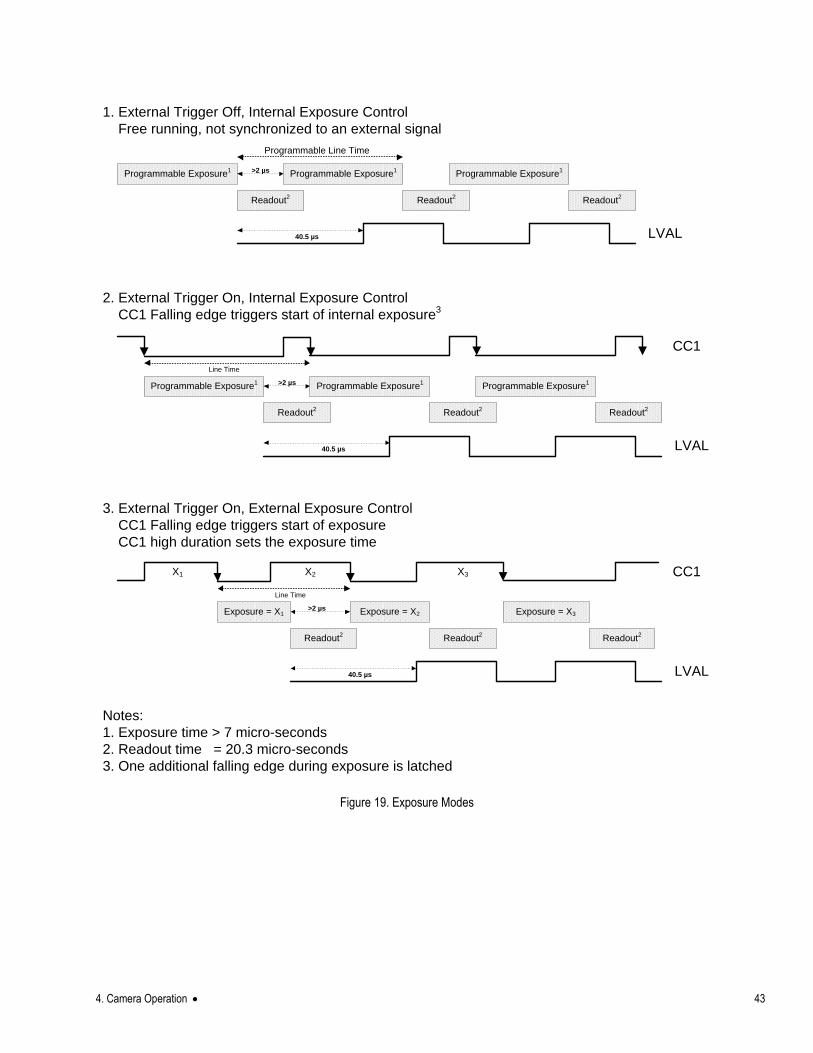
1. External Trigger Off, Internal Exposure Control
Free running, not synchronized to an external signal
Programmable Line Time
Programmable Exposure1
Readout2
40.5 µs
Readout2
>2 µs Programmable Exposure1
Programmable Exposure1
Readout2
LVAL
2. External Trigger On, Internal Exposure Control
CC1 Falling edge triggers start of internal exposure3
Line Time
Programmable Exposure1
Readout2
40.5 µs
Readout2
>2 µs Programmable Exposure1
Programmable Exposure1
Readout2
LVAL
CC1
3. External Trigger On, External Exposure Control
CC1 Falling edge triggers start of exposure
CC1 high duration sets the exposure time
Line Time
Exposure = X1
Readout2
40.5 µs
Readout2
>2 µs
Readout2
LVAL
CC1
Exposure = X2
X1 X2
Exposure = X3
X3
Notes:
1. Exposure time > 7 micro-seconds
2. Readout time = 20.3 micro-seconds
3. One additional falling edge during exposure is latched
Figure 19. Exposure Modes
44 4. Camera Operation
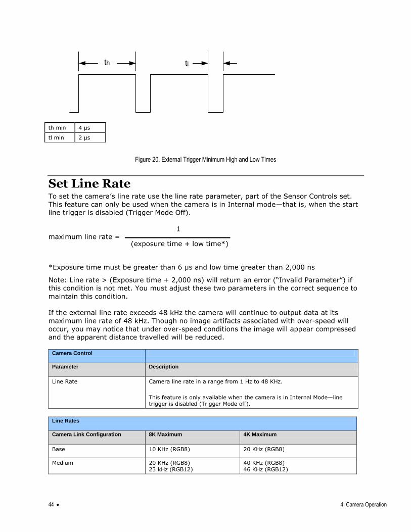
Figure 20. External Trigger Minimum High and Low Times
Set Line Rate To set the camera‘s line rate use the line rate parameter, part of the Sensor Controls set.
This feature can only be used when the camera is in Internal mode—that is, when the start
line trigger is disabled (Trigger Mode Off).
Note: Line rate > (Exposure time + 2,000 ns) will return an error (―Invalid Parameter‖) if
this condition is not met. You must adjust these two parameters in the correct sequence to
maintain this condition.
If the external line rate exceeds 48 kHz the camera will continue to output data at its
maximum line rate of 48 kHz. Though no image artifacts associated with over-speed will
occur, you may notice that under over-speed conditions the image will appear compressed
and the apparent distance travelled will be reduced.
Camera Control
Parameter Description
Line Rate Camera line rate in a range from 1 Hz to 48 KHz.
This feature is only available when the camera is in Internal Mode—line trigger is disabled (Trigger Mode off).
Line Rates
Camera Link Configuration 8K Maximum 4K Maximum
Base 10 KHz (RGB8) 20 KHz (RGB8)
Medium 20 KHz (RGB8) 23 kHz (RGB12)
40 KHz (RGB8) 46 KHz (RGB12)
th tl
th min 4 µs
tl min 2 µs
maximum line rate = 1
(exposure time + low time*)
*Exposure time must be greater than 6 µs and low time greater than 2,000 ns
4. Camera Operation 45
Full 27 KHz (RGB8) 48 KHz (G8)
48 KHz (RGB8) 48 KHz (G8)
Deca 48 KHz (RGBG8) 34 KHz (RGB8)
48 KHz (RGBG8) 48 KHz (RGB8)
Set Exposure Time To set the camera‘s exposure time, use the Exposure Time parameter—a member of the
Sensor Controls set. This feature is only available when the Exposure Mode parameter is
set to Timed. The allowable exposure range is from 4 µs to 3,000 µs, dependent on the
value of the internal line rate.
GenICam parameters:
Sensor Controls > Exposure Time (Timed Exposure Mode) > 4 µs to 3,000 µs.
Control Gain and Black Level The cameras provide gain and black level adjustments in the digital domain for the CMOS
sensor. The gain and black level controls can make small compensations to the acquisition
in situations where lighting varies and the lens iris cannot be easily adjusted. The user can
evaluate gain and black level by using CamExpert.
The parameters that control gain and black level are grouped together in the Sensor
Controls set.
Sensor Controls
Black Level Apply a digital addition after an FPN correction: ± 1/8 of the available range of -32 to +31.
Gain Set the gain as an amplification factor applied to the video signal across all pixels: 1x to 10x.
Set Image Size To set the height of the image, and therefore the number of lines to scan, use the
parameters grouped under the Image Format Control set.
Image Format Control
Control the size of the transmitted image
Width Width of the image.
Height Height of the image in lines.
Pixel Format 8 bit depth to Camera Link.
Test Image Selector Select an internal test image:
Off
Color Ramp
Grey Ramp
46 4. Camera Operation
Set Baud Rate The baud rate sets the speed (in bits per second—bps) of the serial communication port and
is available as part of the Serial Port Control parameters.
Serial Port Control
Action Parameter Options
Control the baud rate used by the camera‘s serial port
Baud Rate 9600 (factory default)
19200
57600
115200
230400
460800
Note: During connection CamExpert
automatically sets the camera to maximum allowable baud.
Number of bits per character used in the serial port
Data Size 8
Parity of the serial port Parity None
Number of stop bits per character used in the serial port
Number of Stop Bits
1
Pixel Format Use the Pixel Format feature, found in the Image Format Control set, to select the format
of the pixel to use during image acquisition.
Image Format Control
Parameter Description
Pixel Format RGB8 / RGB12 / RGBG8 / G8 / BGR8 / BGR12
4. Camera Operation 47
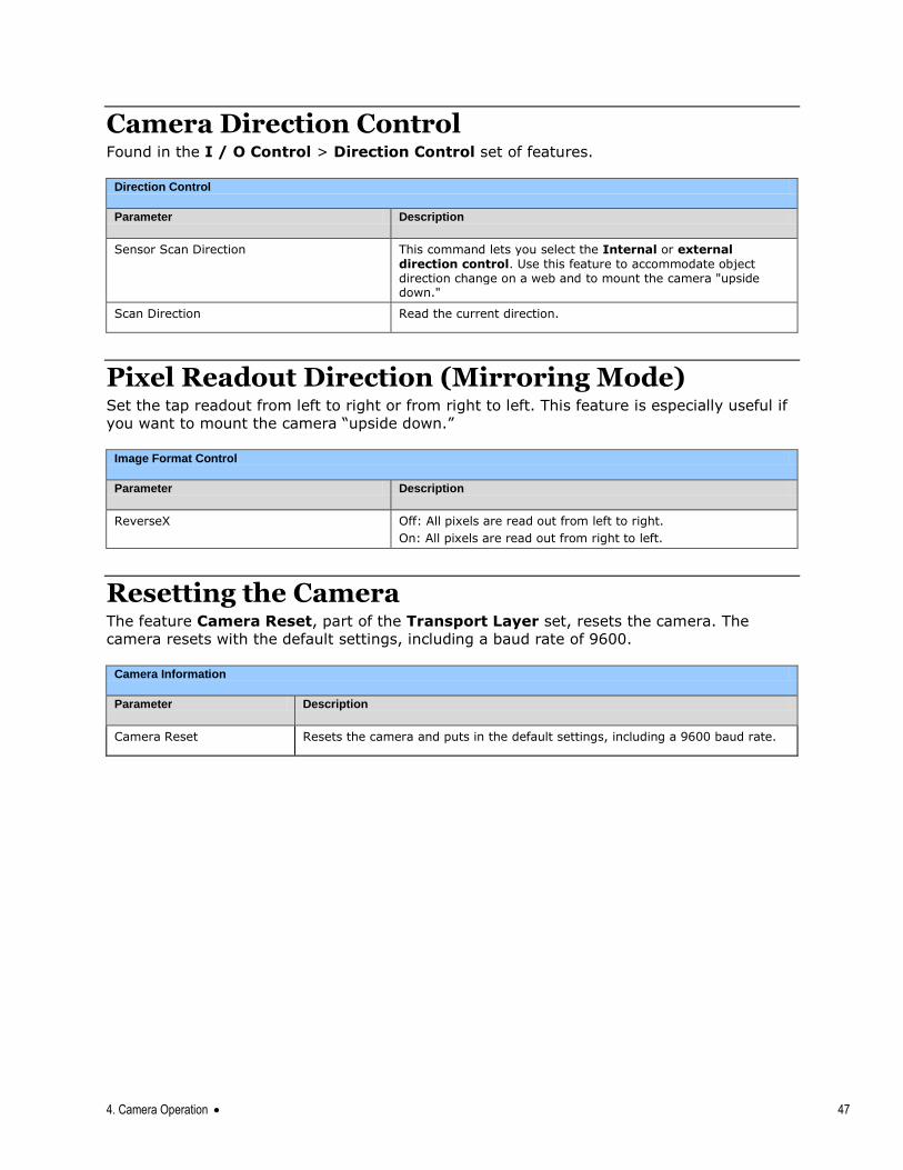
Camera Direction Control Found in the I / O Control > Direction Control set of features.
Direction Control
Parameter Description
Sensor Scan Direction This command lets you select the Internal or external
direction control. Use this feature to accommodate object direction change on a web and to mount the camera "upside down."
Scan Direction Read the current direction.
Pixel Readout Direction (Mirroring Mode) Set the tap readout from left to right or from right to left. This feature is especially useful if
you want to mount the camera ―upside down.‖
Image Format Control
Parameter Description
ReverseX Off: All pixels are read out from left to right.
On: All pixels are read out from right to left.
Resetting the Camera The feature Camera Reset, part of the Transport Layer set, resets the camera. The
camera resets with the default settings, including a baud rate of 9600.
Camera Information
Parameter Description
Camera Reset Resets the camera and puts in the default settings, including a 9600 baud rate.
48 4. Camera Operation
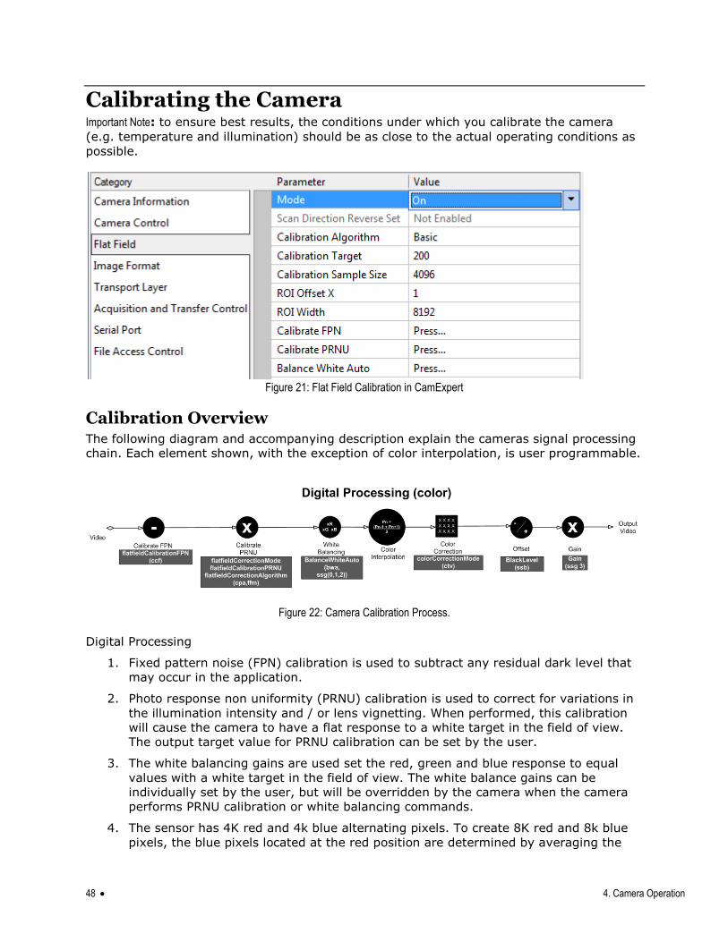
Calibrating the Camera Important Note: to ensure best results, the conditions under which you calibrate the camera
(e.g. temperature and illumination) should be as close to the actual operating conditions as
possible.
Figure 21: Flat Field Calibration in CamExpert
Calibration Overview The following diagram and accompanying description explain the cameras signal processing
chain. Each element shown, with the exception of color interpolation, is user programmable.
Figure 22: Camera Calibration Process.
Digital Processing
1. Fixed pattern noise (FPN) calibration is used to subtract any residual dark level that
may occur in the application.
2. Photo response non uniformity (PRNU) calibration is used to correct for variations in
the illumination intensity and / or lens vignetting. When performed, this calibration
will cause the camera to have a flat response to a white target in the field of view.
The output target value for PRNU calibration can be set by the user.
3. The white balancing gains are used set the red, green and blue response to equal
values with a white target in the field of view. The white balance gains can be
individually set by the user, but will be overridden by the camera when the camera
performs PRNU calibration or white balancing commands.
4. The sensor has 4K red and 4k blue alternating pixels. To create 8K red and 8k blue
pixels, the blue pixels located at the red position are determined by averaging the
4. Camera Operation 49
two adjacent blue pixels. The same process is used for the red pixels. This is the only
interpolation algorithm provided by the camera.
5. Color correction is available for those users that need to compensate for the spectral
transmission characteristics of the sensors color filters and the customers light
source. This can be achieved by imaging a MacBeth Chart© illuminated by the
application‘s light source and processing the image using a color correction
demonstration tool provided as part of Teledyne DALSA‘s Sapera Processing
software. This tool will generate the desired color correction file that can be
downloaded to the camera.
Note: Prior to imaging the MacBeth Chart©, the camera should have been calibrated
with a white reference in place of the MacBeth Chart© and color correction must be
turned off. The calibration process will ensure the camera output is uniform and
white balanced.
6. The introduction of offsets has limited value in color applications as it will cause color
distortion. However, the camera has the ability to add either a positive or negative
offset as required by a specific application. This offset can be useful when trying to
measure dark noise where black level clipping will cause an error in the result.
7. A single overall system gain is applied equally to all three colors. It will therefore not
cause color distortion when changed.
8. A factory setting for white LED color correction can be applied, if needed.
Calibration The goal of calibration is to produce a uniform, white balanced and, if required, color
corrected image at the desired level out of the camera when it is imaging a uniform white
object, using the optical setup of the user‘s application.
The user should configure the camera to use the EXSYNC and exposure timing they desire
plus adjust the light level for normal operation. The lens should be at the desired
magnification, aperture and be in focus. As the white reference located at the object plane
will be in focus, any features on its surface (e.g. dust, scratches) will end up in the
calibration profile of the camera. To avoid this, use a clean white plastic or ceramic material,
not paper. Ideally, the white object should move during the calibration process as the
averaging process of the camera will diminish the effects on any small variation in the white
reference.
The user may wish to start the calibration process by evaluating the characteristics of their
setup with no calibration enabled. This can be readily achieved by disabling FPN, PRNU &
color correction coefficients, setting white balance red, green and blue gains to one, and the
system gain to one.
Begin by adjusting the system gain until the peak intensity of the three colors is at the
desired DN level. You may want to use the white balance gains to adjust the peak of each
color to be a similar DN value, but this is not necessary. Before proceeding any further, it is
desirable to complete an FPN calibration. This is best performed using a lens cap to ensure
no light gets into the camera. Once complete, a PRNU calibration can be performed using a
target value you want all the pixels to achieve. This target value can be higher or lower than
the peak values you observed while initially setting up the camera. Once PRNU calibration is
complete, it will take several seconds, all three colors should be at the target value, white
balance gains will have been adjusted to suit the cameras optimum setup for a balanced
white output, and the correction coefficient will be enabled. The system gain will remain as
50 4. Camera Operation
originally set. The coefficient and gain parameters, timing and control configuration etc can
be stored in any one of eight user sets and automatically retrieved at power up or by user
selection. If a color correction matrix is desired, the user can download and save a color correction file derived from the process described above. Note: For the color correction to be
affective, the camera should have a white balanced output when color correction is off.
1. Flat Field This Flat Field set contains a number of features that are used to correct image distortion
due to lens vignetting and uneven illumination. .
Note:
1. Flat field coefficients consist of an offset and gain for each pixel.
2. These are the first user corrections applied to the image.
3. The flat field coefficients are saved and loaded with the user
set.
Parameter Description
flatfieldCorrectionMode Off – Flat field correction coefficients are not applied.
On – Flat field correction coefficients are applied.
Initialize – Sending this value will reset all current coefficients (offsets to 0 and flat field gains to 1x).
flatfieldCorrectionAlgorithm Basic – Direct calculation of coefficients based on current average line values and target.
LowPass – A low pass filter is first applied to the current average line values before calculating the coefficients. Use this algorithm if the calibration target is not uniform white or it s not possible to defocus the image. Because of the low pass filter this algorithm is not able to correct pixel-to-pixel variations and so it is preferable to use the ―Basic‖ algorithm if possible.
flatfieldCalibrationTarget After calibration all pixels will be scaled to output this level
Range: 8 bit, 0 to 255 DN
flatfieldCalibrationSampleSize Number of lines to average when calibrating
2048 or 4096
flatfieldCalibrationROIOffsetX Together with ―flatfieldCalibrationROIWidth‖ specifies the range of pixels to
be calibrated. Pixel coefficients outside this range are not changed. It is possible to calibrate different regions sequentially.
flatfieldCalibrationROIWidth Together with ―flatfieldCalibrationROIOffset‖ specifies the range of pixels to
be calibrated. Pixel coefficients outside this range are not changed. It is possible to calibrate different regions sequentially.
flatfieldCalibrationFPN This feature may not be of use to many users as the camera already
subtracts true ―dark current‖, but it may be useful for some to provide a per pixel offset correction.
Range 0 to 31 DN, 8 bit
Default value is 0 DN for each pixel
flatfieldCalibrationPRNU Use ―flatfieldCorrectionAlgorithm‖ to calculate the per pixel gain to achieve the specified target output.
Max 15.9998x
Default 1x
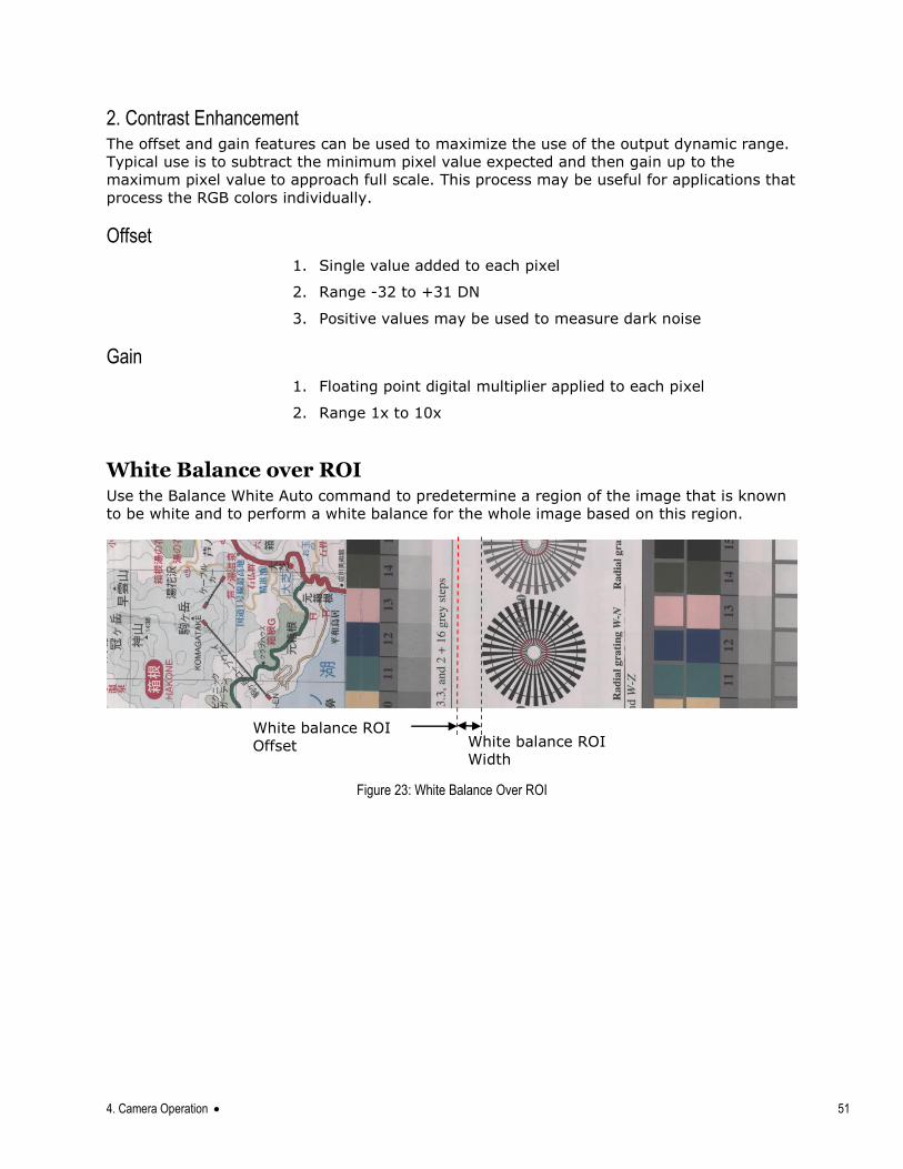
4. Camera Operation 51
2. Contrast Enhancement The offset and gain features can be used to maximize the use of the output dynamic range.
Typical use is to subtract the minimum pixel value expected and then gain up to the
maximum pixel value to approach full scale. This process may be useful for applications that
process the RGB colors individually.
Offset
1. Single value added to each pixel
2. Range -32 to +31 DN
3. Positive values may be used to measure dark noise
Gain
1. Floating point digital multiplier applied to each pixel
2. Range 1x to 10x
White Balance over ROI Use the Balance White Auto command to predetermine a region of the image that is known
to be white and to perform a white balance for the whole image based on this region.
Figure 23: White Balance Over ROI
White balance ROI
Offset White balance ROI Width
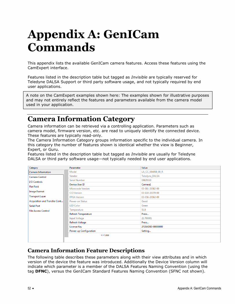
52 Appendix A: GenICam Commands
Appendix A: GenICam Commands This appendix lists the available GenICam camera features. Access these features using the
CamExpert interface.
Features listed in the description table but tagged as Invisible are typically reserved for
Teledyne DALSA Support or third party software usage, and not typically required by end
user applications.
Camera Information Category Camera information can be retrieved via a controlling application. Parameters such as
camera model, firmware version, etc. are read to uniquely identify the connected device.
These features are typically read-only.
The Camera Information Category groups information specific to the individual camera. In
this category the number of features shown is identical whether the view is Beginner,
Expert, or Guru.
Features listed in the description table but tagged as Invisible are usually for Teledyne
DALSA or third party software usage—not typically needed by end user applications.
Camera Information Feature Descriptions The following table describes these parameters along with their view attributes and in which
version of the device the feature was introduced. Additionally the Device Version column will
indicate which parameter is a member of the DALSA Features Naming Convention (using the
tag DFNC), versus the GenICam Standard Features Naming Convention (SFNC not shown).
A note on the CamExpert examples shown here: The examples shown for illustrative purposes
and may not entirely reflect the features and parameters available from the camera model used in your application.
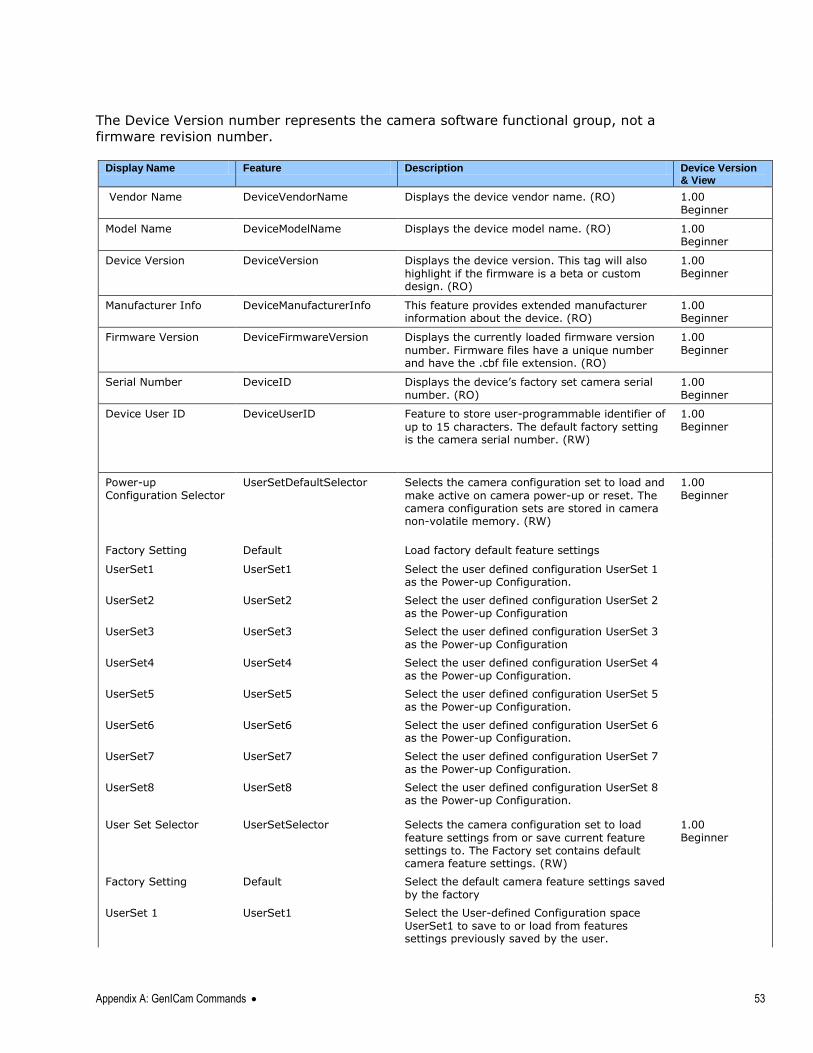
Appendix A: GenICam Commands 53
The Device Version number represents the camera software functional group, not a
firmware revision number.
Display Name Feature Description Device Version
& View
Vendor Name DeviceVendorName Displays the device vendor name. (RO) 1.00 Beginner
Model Name DeviceModelName Displays the device model name. (RO) 1.00 Beginner
Device Version DeviceVersion Displays the device version. This tag will also
highlight if the firmware is a beta or custom design. (RO)
1.00 Beginner
Manufacturer Info DeviceManufacturerInfo This feature provides extended manufacturer information about the device. (RO)
1.00 Beginner
Firmware Version DeviceFirmwareVersion Displays the currently loaded firmware version
number. Firmware files have a unique number and have the .cbf file extension. (RO)
1.00 Beginner
Serial Number DeviceID Displays the device‘s factory set camera serial number. (RO)
1.00 Beginner
Device User ID DeviceUserID Feature to store user-programmable identifier of
up to 15 characters. The default factory setting is the camera serial number. (RW)
1.00 Beginner
Power-up Configuration Selector
UserSetDefaultSelector Selects the camera configuration set to load and
make active on camera power-up or reset. The camera configuration sets are stored in camera non-volatile memory. (RW)
1.00 Beginner
Factory Setting Default Load factory default feature settings
UserSet1 UserSet1 Select the user defined configuration UserSet 1 as the Power-up Configuration.
UserSet2 UserSet2 Select the user defined configuration UserSet 2 as the Power-up Configuration
UserSet3 UserSet3 Select the user defined configuration UserSet 3 as the Power-up Configuration
UserSet4 UserSet4 Select the user defined configuration UserSet 4 as the Power-up Configuration.
UserSet5 UserSet5 Select the user defined configuration UserSet 5 as the Power-up Configuration.
UserSet6 UserSet6 Select the user defined configuration UserSet 6 as the Power-up Configuration.
UserSet7 UserSet7 Select the user defined configuration UserSet 7 as the Power-up Configuration.
UserSet8 UserSet8 Select the user defined configuration UserSet 8 as the Power-up Configuration.
User Set Selector UserSetSelector Selects the camera configuration set to load
feature settings from or save current feature settings to. The Factory set contains default camera feature settings. (RW)
1.00 Beginner
Factory Setting Default Select the default camera feature settings saved by the factory
UserSet 1 UserSet1 Select the User-defined Configuration space UserSet1 to save to or load from features settings previously saved by the user.
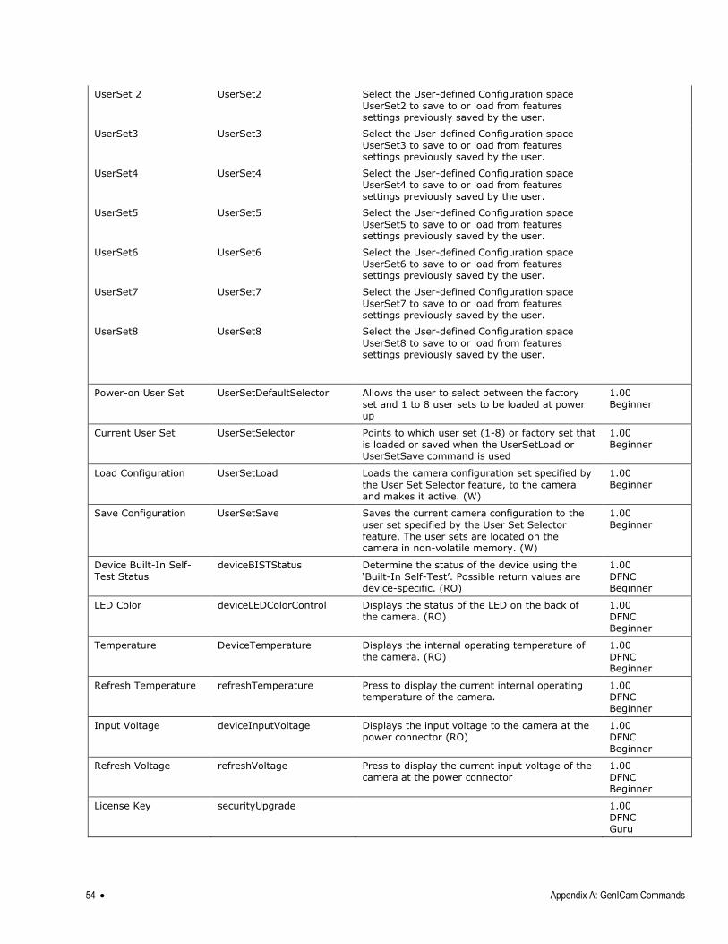
54 Appendix A: GenICam Commands
UserSet 2 UserSet2 Select the User-defined Configuration space
UserSet2 to save to or load from features settings previously saved by the user.
UserSet3 UserSet3 Select the User-defined Configuration space
UserSet3 to save to or load from features settings previously saved by the user.
UserSet4 UserSet4 Select the User-defined Configuration space UserSet4 to save to or load from features settings previously saved by the user.
UserSet5 UserSet5 Select the User-defined Configuration space
UserSet5 to save to or load from features settings previously saved by the user.
UserSet6 UserSet6 Select the User-defined Configuration space UserSet6 to save to or load from features settings previously saved by the user.
UserSet7 UserSet7 Select the User-defined Configuration space
UserSet7 to save to or load from features settings previously saved by the user.
UserSet8 UserSet8 Select the User-defined Configuration space
UserSet8 to save to or load from features settings previously saved by the user.
Power-on User Set UserSetDefaultSelector Allows the user to select between the factory set and 1 to 8 user sets to be loaded at power up
1.00 Beginner
Current User Set UserSetSelector Points to which user set (1-8) or factory set that
is loaded or saved when the UserSetLoad or UserSetSave command is used
1.00 Beginner
Load Configuration UserSetLoad Loads the camera configuration set specified by
the User Set Selector feature, to the camera and makes it active. (W)
1.00 Beginner
Save Configuration UserSetSave Saves the current camera configuration to the
user set specified by the User Set Selector feature. The user sets are located on the camera in non-volatile memory. (W)
1.00 Beginner
Device Built-In Self-Test Status
deviceBISTStatus Determine the status of the device using the
‗Built-In Self-Test‘. Possible return values are device-specific. (RO)
1.00
DFNC Beginner
LED Color deviceLEDColorControl Displays the status of the LED on the back of the camera. (RO)
1.00 DFNC Beginner
Temperature DeviceTemperature Displays the internal operating temperature of the camera. (RO)
1.00
DFNC Beginner
Refresh Temperature refreshTemperature Press to display the current internal operating temperature of the camera.
1.00 DFNC Beginner
Input Voltage deviceInputVoltage Displays the input voltage to the camera at the power connector (RO)
1.00
DFNC Beginner
Refresh Voltage refreshVoltage Press to display the current input voltage of the camera at the power connector
1.00
DFNC Beginner
License Key securityUpgrade 1.00
DFNC Guru
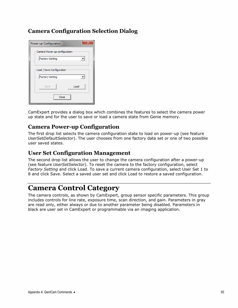
Appendix A: GenICam Commands 55
Camera Configuration Selection Dialog
CamExpert provides a dialog box which combines the features to select the camera power
up state and for the user to save or load a camera state from Genie memory.
Camera Power-up Configuration The first drop list selects the camera configuration state to load on power-up (see feature
UserSetDefaultSelector). The user chooses from one factory data set or one of two possible
user saved states.
User Set Configuration Management The second drop list allows the user to change the camera configuration after a power-up
(see feature UserSetSelector). To reset the camera to the factory configuration, select
Factory Setting and click Load. To save a current camera configuration, select User Set 1 to
8 and click Save. Select a saved user set and click Load to restore a saved configuration.
Camera Control Category The camera controls, as shown by CamExpert, group sensor specific parameters. This group
includes controls for line rate, exposure time, scan direction, and gain. Parameters in gray
are read only, either always or due to another parameter being disabled. Parameters in
black are user set in CamExpert or programmable via an imaging application.
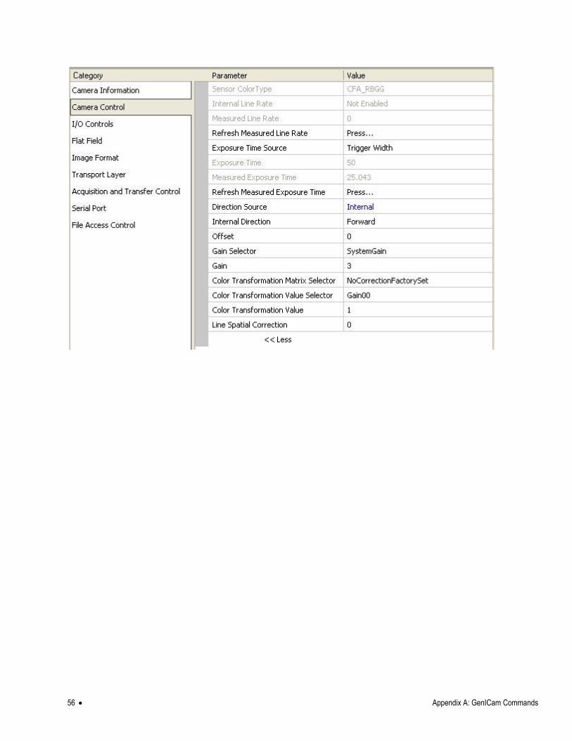
56 Appendix A: GenICam Commands
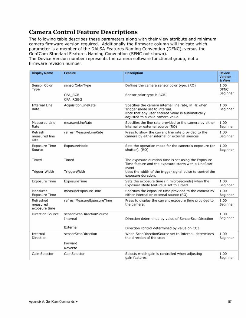
Appendix A: GenICam Commands 57
Camera Control Feature Descriptions The following table describes these parameters along with their view attribute and minimum
camera firmware version required. Additionally the firmware column will indicate which
parameter is a member of the DALSA Features Naming Convention (DFNC), versus the
GenICam Standard Features Naming Convention (SFNC not shown).
The Device Version number represents the camera software functional group, not a
firmware revision number.
Display Name Feature Description Device
Version & View
Sensor Color Type
sensorColorType Defines the camera sensor color type. (RO) 1.00
DFNC Beginner
CFA_RGB
CFA_RGBG
Sensor color type is RGB
Internal Line Rate
AcquisitionLineRate Specifies the camera internal line rate, in Hz when Trigger mode set to internal. Note that any user entered value is automatically adjusted to a valid camera value.
1.00 Beginner
Measured Line Rate
measureLineRate Specifies the line rate provided to the camera by either internal or external source (RO)
1.00 Beginner
Refresh
measured line rate
refreshMeasureLineRate Press to show the current line rate provided to the camera by either internal or external sources
1.00 Beginner
Exposure Time Source
ExposureMode Sets the operation mode for the camera‘s exposure (or shutter). (RO)
1.00 Beginner
Timed Trigger Width
Timed TriggerWidth
The exposure duration time is set using the Exposure Time feature and the exposure starts with a LineStart event. Uses the width of the trigger signal pulse to control the exposure duration.
Exposure Time ExposureTime Sets the exposure time (in microseconds) when the Exposure Mode feature is set to Timed.
1.00 Beginner
Measured Exposure Time
measureExposureTime Specifies the exposure time provided to the camera by either internal or external source (RO)
1.00 Beginner
Refreshed
measured exposure time
refreshMeasureExposureTime Press to display the current exposure time provided to the camera.
1.00 Beginner
Direction Source sensorScanDirectionSource
Internal
External
Direction determined by value of SensorScanDirection
Direction control determined by value on CC3
1.00 Beginner
Internal Direction
sensorScanDirection
Forward
Reverse
When ScanDirectionSource set to Internal, determines the direction of the scan
1.00 Beginner
Gain Selector GainSelector Selects which gain is controlled when adjusting gain features.
1.00 Beginner
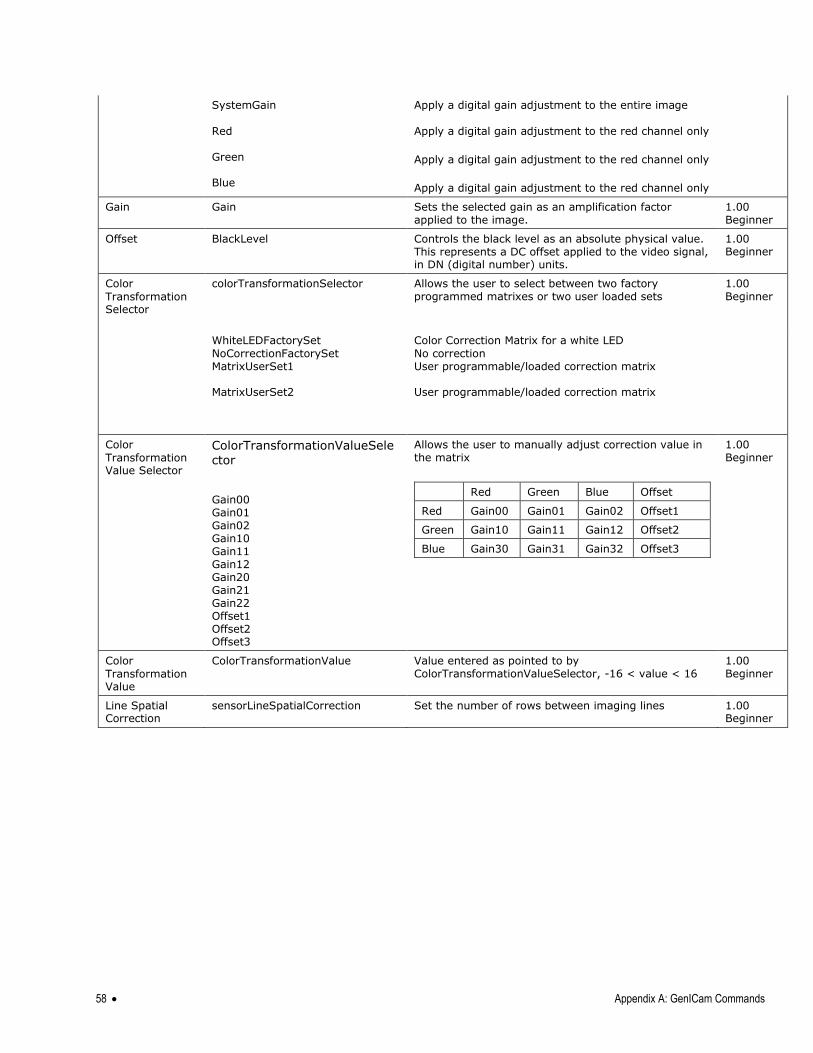
58 Appendix A: GenICam Commands
SystemGain
Red Green Blue
Apply a digital gain adjustment to the entire image
Apply a digital gain adjustment to the red channel only
Apply a digital gain adjustment to the red channel only
Apply a digital gain adjustment to the red channel only
Gain Gain Sets the selected gain as an amplification factor applied to the image.
1.00 Beginner
Offset BlackLevel Controls the black level as an absolute physical value. This represents a DC offset applied to the video signal, in DN (digital number) units.
1.00 Beginner
Color
Transformation Selector
colorTransformationSelector
Allows the user to select between two factory programmed matrixes or two user loaded sets
1.00 Beginner
WhiteLEDFactorySet
NoCorrectionFactorySet MatrixUserSet1 MatrixUserSet2
Color Correction Matrix for a white LED
No correction User programmable/loaded correction matrix User programmable/loaded correction matrix
Color
Transformation Value Selector
ColorTransformationValueSele
ctor Gain00 Gain01 Gain02 Gain10 Gain11 Gain12 Gain20 Gain21 Gain22 Offset1 Offset2 Offset3
Allows the user to manually adjust correction value in the matrix
Red Green Blue Offset
Red Gain00 Gain01 Gain02 Offset1
Green Gain10 Gain11 Gain12 Offset2
Blue Gain30 Gain31 Gain32 Offset3
1.00 Beginner
Color
Transformation Value
ColorTransformationValue Value entered as pointed to by ColorTransformationValueSelector, -16 < value < 16
1.00 Beginner
Line Spatial Correction
sensorLineSpatialCorrection Set the number of rows between imaging lines 1.00 Beginner
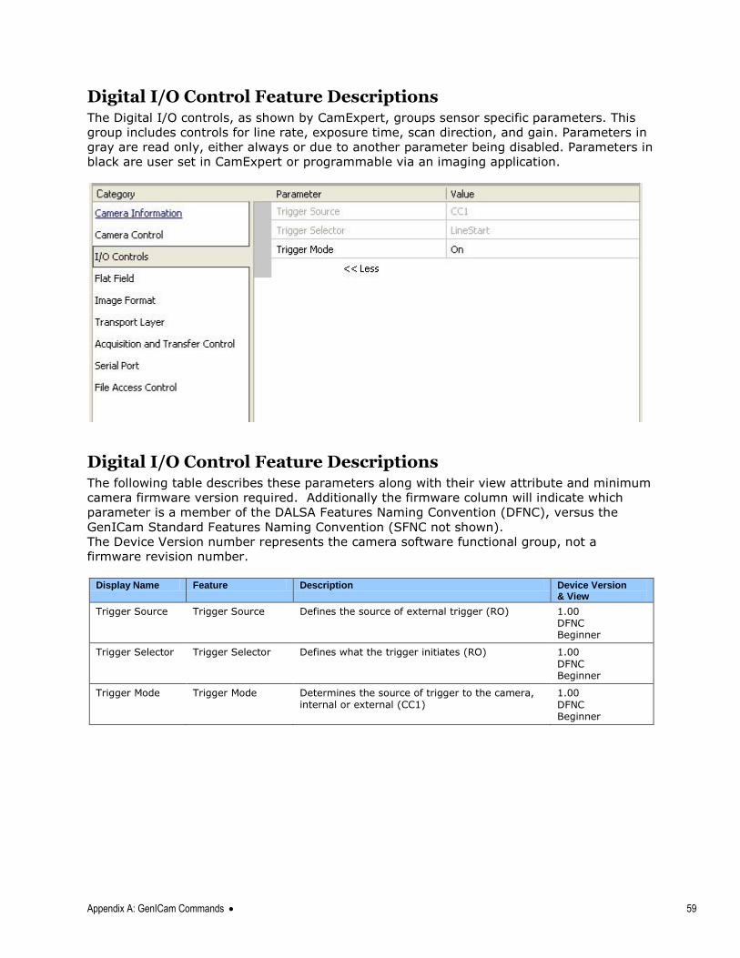
Appendix A: GenICam Commands 59
Digital I/O Control Feature Descriptions The Digital I/O controls, as shown by CamExpert, groups sensor specific parameters. This
group includes controls for line rate, exposure time, scan direction, and gain. Parameters in
gray are read only, either always or due to another parameter being disabled. Parameters in
black are user set in CamExpert or programmable via an imaging application.
Digital I/O Control Feature Descriptions The following table describes these parameters along with their view attribute and minimum
camera firmware version required. Additionally the firmware column will indicate which
parameter is a member of the DALSA Features Naming Convention (DFNC), versus the
GenICam Standard Features Naming Convention (SFNC not shown).
The Device Version number represents the camera software functional group, not a
firmware revision number.
Display Name Feature Description Device Version
& View
Trigger Source Trigger Source Defines the source of external trigger (RO) 1.00 DFNC Beginner
Trigger Selector Trigger Selector Defines what the trigger initiates (RO) 1.00
DFNC Beginner
Trigger Mode Trigger Mode Determines the source of trigger to the camera, internal or external (CC1)
1.00
DFNC Beginner
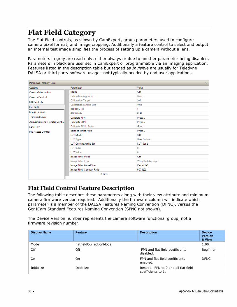
60 Appendix A: GenICam Commands
Flat Field Category The Flat Field controls, as shown by CamExpert, group parameters used to configure
camera pixel format, and image cropping. Additionally a feature control to select and output
an internal test image simplifies the process of setting up a camera without a lens.
Parameters in gray are read only, either always or due to another parameter being disabled.
Parameters in black are user set in CamExpert or programmable via an imaging application.
Features listed in the description table but tagged as Invisible are usually for Teledyne
DALSA or third party software usage—not typically needed by end user applications.
Flat Field Control Feature Description The following table describes these parameters along with their view attribute and minimum
camera firmware version required. Additionally the firmware column will indicate which
parameter is a member of the DALSA Features Naming Convention (DFNC), versus the
GenICam Standard Features Naming Convention (SFNC not shown).
The Device Version number represents the camera software functional group, not a
firmware revision number.
Display Name Feature Description Device
Version & View
Mode flatfieldCorrectionMode 1.00
Off Off FPN and flat field coefficients disabled.
Beginner
On On FPN and flat field coefficients enabled.
DFNC
Initialize Initialize Reset all FPN to 0 and all flat field coefficients to 1.
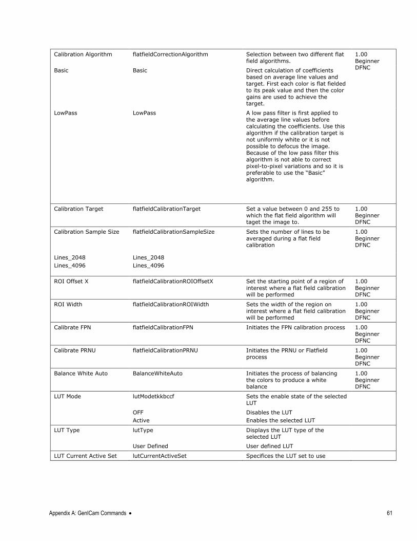
Appendix A: GenICam Commands 61
Calibration Algorithm flatfieldCorrectionAlgorithm Selection between two different flat field algorithms.
1.00
Beginner DFNC
Basic Basic Direct calculation of coefficients based on average line values and target. First each color is flat fielded to its peak value and then the color gains are used to achieve the target.
LowPass LowPass A low pass filter is first applied to
the average line values before calculating the coefficients. Use this algorithm if the calibration target is not uniformly white or it is not possible to defocus the image. Because of the low pass filter this algorithm is not able to correct pixel-to-pixel variations and so it is preferable to use the ―Basic‖ algorithm.
Calibration Target flatfieldCalibrationTarget Set a value between 0 and 255 to which the flat field algorithm will taget the image to.
1.00 Beginner DFNC
Calibration Sample Size flatfieldCalibrationSampleSize Sets the number of lines to be
averaged during a flat field calibration
1.00
Beginner DFNC
Lines_2048
Lines_4096
Lines_2048
Lines_4096
ROI Offset X
flatfieldCalibrationROIOffsetX
Set the starting point of a region of
interest where a flat field calibration will be performed
1.00
Beginner DFNC
ROI Width
flatfieldCalibrationROIWidth
Sets the width of the region on
interest where a flat field calibration will be performed
1.00
Beginner DFNC
Calibrate FPN
flatfieldCalibrationFPN
Initiates the FPN calibration process 1.00 Beginner DFNC
Calibrate PRNU
flatfieldCalibrationPRNU
Initiates the PRNU or Flatfield process
1.00
Beginner DFNC
Balance White Auto
BalanceWhiteAuto
Initiates the process of balancing the colors to produce a white balance
1.00 Beginner DFNC
LUT Mode lutModetkkbccf Sets the enable state of the selected LUT
OFF
Active
Disables the LUT
Enables the selected LUT
LUT Type lutType Displays the LUT type of the selected LUT
User Defined User defined LUT
LUT Current Active Set lutCurrentActiveSet Specifices the LUT set to use
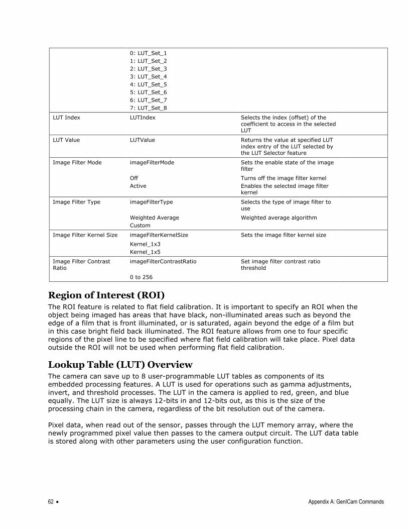
62 Appendix A: GenICam Commands
0: LUT_Set_1
1: LUT_Set_2
2: LUT_Set_3
3: LUT_Set_4
4: LUT_Set_5
5: LUT_Set_6
6: LUT_Set_7
7: LUT_Set_8
LUT Index LUTIndex Selects the index (offset) of the coefficient to access in the selected LUT
LUT Value LUTValue Returns the value at specified LUT
index entry of the LUT selected by the LUT Selector feature
Image Filter Mode imageFilterMode Sets the enable state of the image filter
Off
Active
Turns off the image filter kernel
Enables the selected image filter kernel
Image Filter Type imageFilterType Selects the type of image filter to use
Weighted Average
Custom
Weighted average algorithm
Image Filter Kernel Size imageFilterKernelSize Sets the image filter kernel size
Kernel_1x3
Kernel_1x5
Image Filter Contrast Ratio
imageFilterContrastRatio Set image filter contrast ratio threshold
0 to 256
Region of Interest (ROI) The ROI feature is related to flat field calibration. It is important to specify an ROI when the
object being imaged has areas that have black, non-illuminated areas such as beyond the
edge of a film that is front illuminated, or is saturated, again beyond the edge of a film but
in this case bright field back illuminated. The ROI feature allows from one to four specific
regions of the pixel line to be specified where flat field calibration will take place. Pixel data
outside the ROI will not be used when performing flat field calibration.
Lookup Table (LUT) Overview The camera can save up to 8 user-programmable LUT tables as components of its
embedded processing features. A LUT is used for operations such as gamma adjustments,
invert, and threshold processes. The LUT in the camera is applied to red, green, and blue
equally. The LUT size is always 12-bits in and 12-bits out, as this is the size of the
processing chain in the camera, regardless of the bit resolution out of the camera.
Pixel data, when read out of the sensor, passes through the LUT memory array, where the
newly programmed pixel value then passes to the camera output circuit. The LUT data table
is stored along with other parameters using the user configuration function.
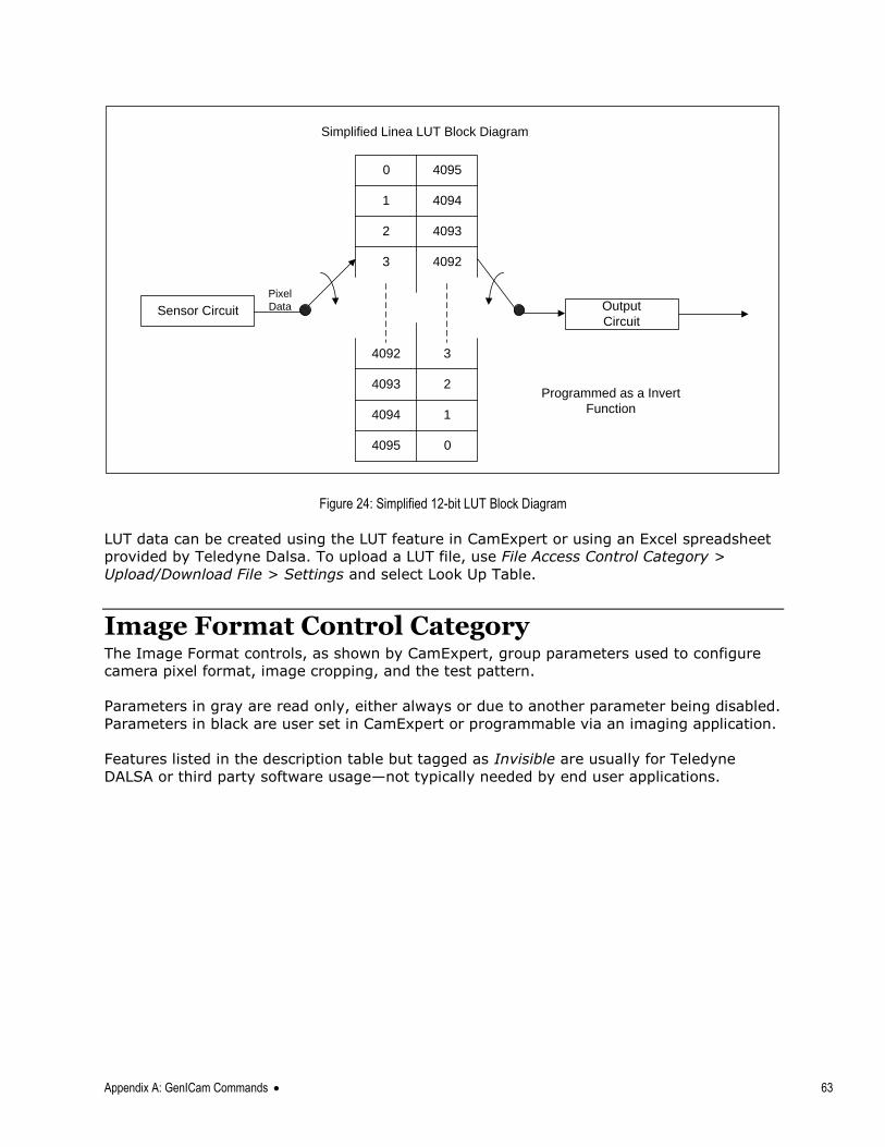
Appendix A: GenICam Commands 63
Output
Circuit
0
1
2
3
0
1
2
3
4095
4094
4093
4092
4095
4094
4093
4092
Sensor Circuit
Simplified Linea LUT Block Diagram
Programmed as a Invert
Function
Pixel
Data
Figure 24: Simplified 12-bit LUT Block Diagram
LUT data can be created using the LUT feature in CamExpert or using an Excel spreadsheet
provided by Teledyne Dalsa. To upload a LUT file, use File Access Control Category >
Upload/Download File > Settings and select Look Up Table.
Image Format Control Category The Image Format controls, as shown by CamExpert, group parameters used to configure
camera pixel format, image cropping, and the test pattern.
Parameters in gray are read only, either always or due to another parameter being disabled.
Parameters in black are user set in CamExpert or programmable via an imaging application.
Features listed in the description table but tagged as Invisible are usually for Teledyne
DALSA or third party software usage—not typically needed by end user applications.
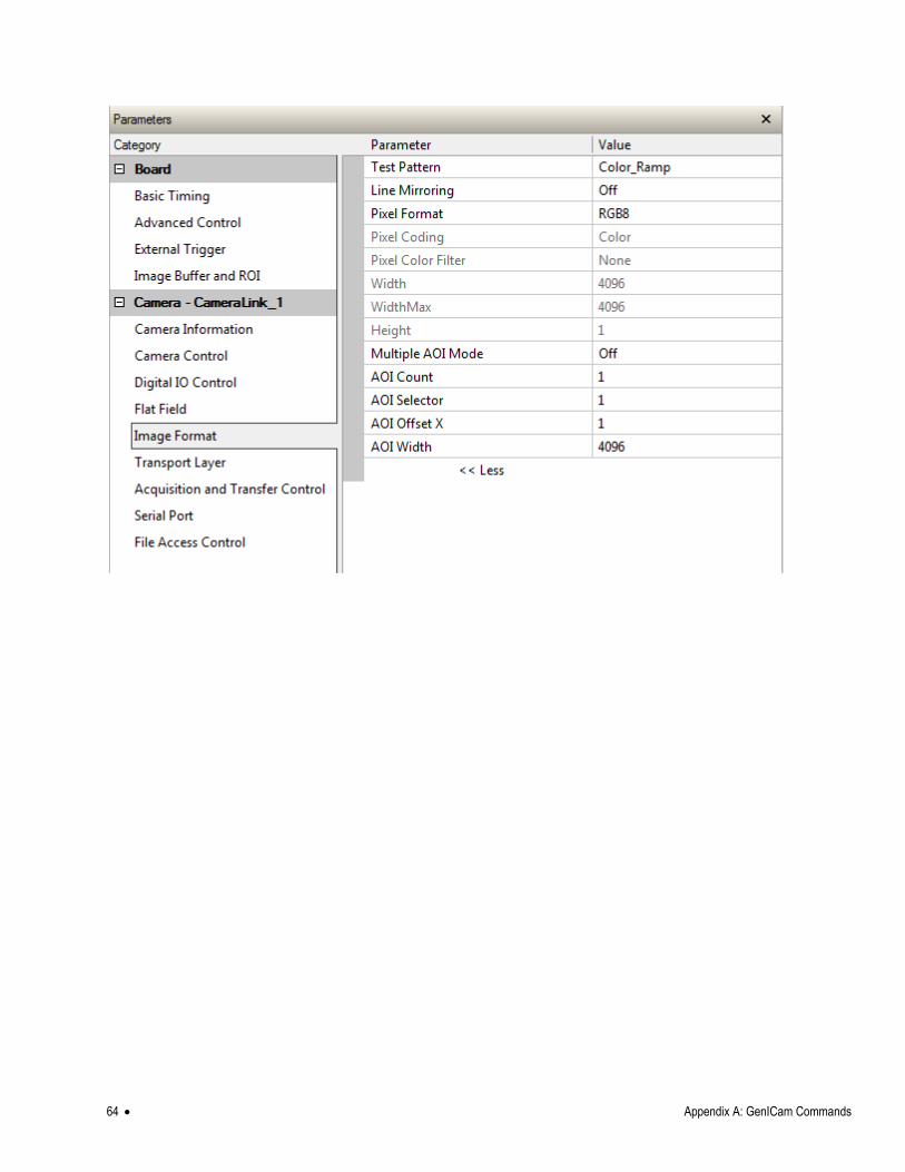
64 Appendix A: GenICam Commands
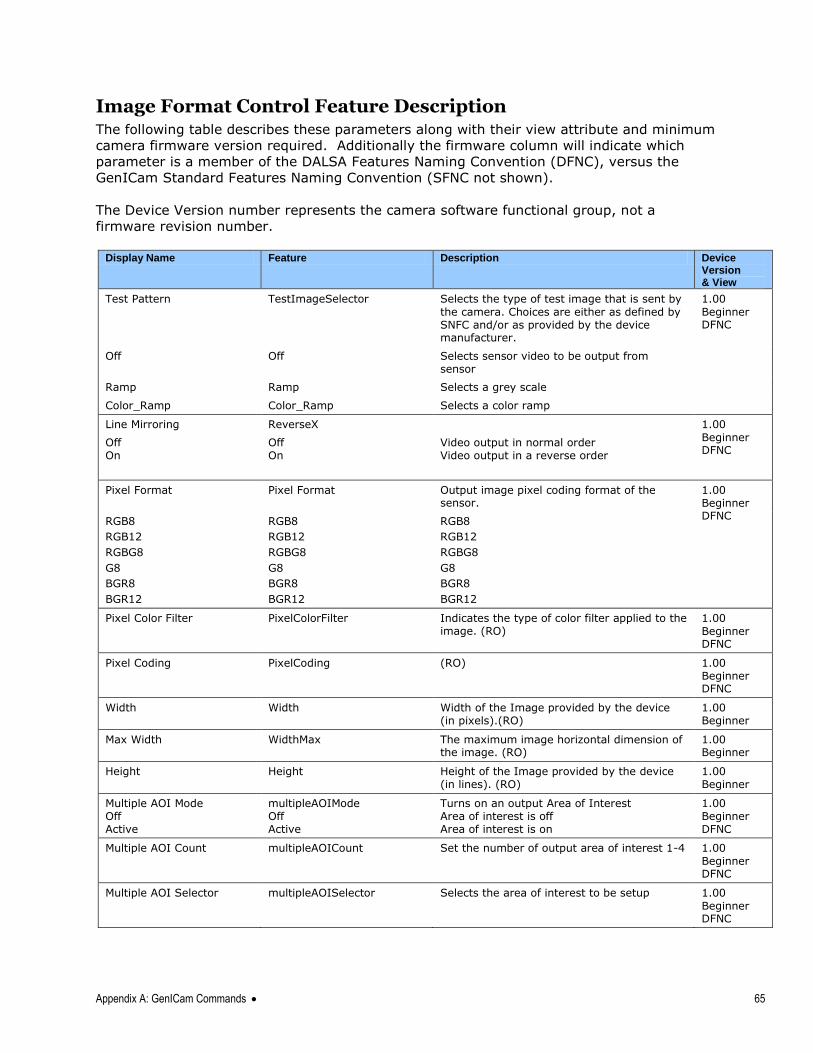
Appendix A: GenICam Commands 65
Image Format Control Feature Description The following table describes these parameters along with their view attribute and minimum
camera firmware version required. Additionally the firmware column will indicate which
parameter is a member of the DALSA Features Naming Convention (DFNC), versus the
GenICam Standard Features Naming Convention (SFNC not shown).
The Device Version number represents the camera software functional group, not a
firmware revision number.
Display Name Feature Description Device
Version & View
Test Pattern
TestImageSelector
Selects the type of test image that is sent by
the camera. Choices are either as defined by SNFC and/or as provided by the device manufacturer.
1.00
Beginner DFNC
Off Off Selects sensor video to be output from sensor
Ramp Ramp Selects a grey scale
Color_Ramp Color_Ramp Selects a color ramp
Line Mirroring ReverseX 1.00
Beginner DFNC
Off On
Off On
Video output in normal order Video output in a reverse order
Pixel Format Pixel Format Output image pixel coding format of the sensor.
1.00 Beginner DFNC
RGB8
RGB12
RGBG8
G8
BGR8
BGR12
RGB8
RGB12
RGBG8
G8
BGR8
BGR12
RGB8
RGB12
RGBG8
G8
BGR8
BGR12
Pixel Color Filter PixelColorFilter Indicates the type of color filter applied to the image. (RO)
1.00
Beginner DFNC
Pixel Coding PixelCoding (RO) 1.00 Beginner DFNC
Width Width Width of the Image provided by the device (in pixels).(RO)
1.00 Beginner
Max Width WidthMax The maximum image horizontal dimension of the image. (RO)
1.00 Beginner
Height Height Height of the Image provided by the device (in lines). (RO)
1.00 Beginner
Multiple AOI Mode Off Active
multipleAOIMode Off Active
Turns on an output Area of Interest Area of interest is off Area of interest is on
1.00 Beginner DFNC
Multiple AOI Count
multipleAOICount
Set the number of output area of interest 1-4 1.00
Beginner DFNC
Multiple AOI Selector
multipleAOISelector
Selects the area of interest to be setup 1.00
Beginner DFNC
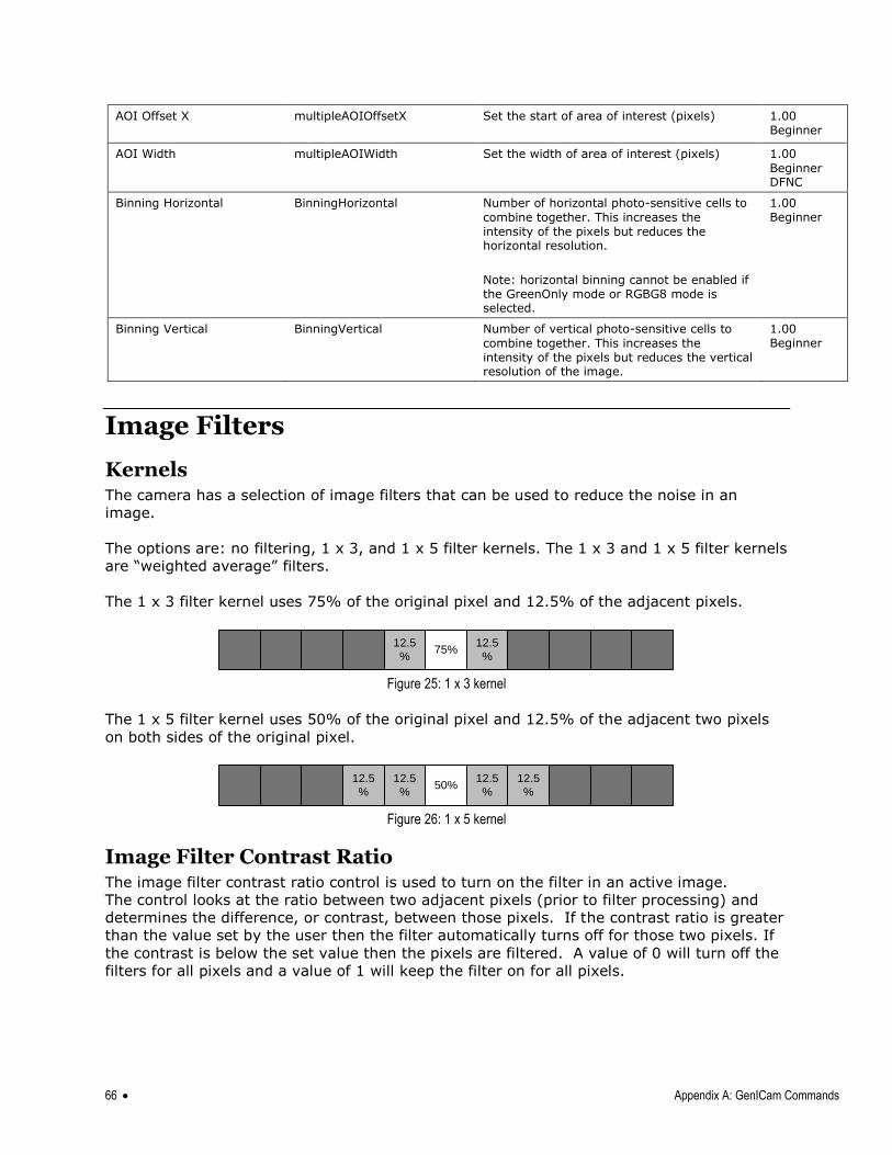
66 Appendix A: GenICam Commands
AOI Offset X
multipleAOIOffsetX
Set the start of area of interest (pixels) 1.00 Beginner
AOI Width
multipleAOIWidth
Set the width of area of interest (pixels) 1.00
Beginner DFNC
Binning Horizontal BinningHorizontal Number of horizontal photo-sensitive cells to
combine together. This increases the intensity of the pixels but reduces the horizontal resolution.
Note: horizontal binning cannot be enabled if the GreenOnly mode or RGBG8 mode is selected.
1.00 Beginner
Binning Vertical BinningVertical Number of vertical photo-sensitive cells to
combine together. This increases the intensity of the pixels but reduces the vertical resolution of the image.
1.00 Beginner
Image Filters
Kernels The camera has a selection of image filters that can be used to reduce the noise in an
image.
The options are: no filtering, 1 x 3, and 1 x 5 filter kernels. The 1 x 3 and 1 x 5 filter kernels
are ―weighted average‖ filters.
The 1 x 3 filter kernel uses 75% of the original pixel and 12.5% of the adjacent pixels.
12.5
%75%
12.5
%
Figure 25: 1 x 3 kernel
The 1 x 5 filter kernel uses 50% of the original pixel and 12.5% of the adjacent two pixels
on both sides of the original pixel.
12.5
%50%
12.5
%
12.5
%
12.5
%
Figure 26: 1 x 5 kernel
Image Filter Contrast Ratio The image filter contrast ratio control is used to turn on the filter in an active image.
The control looks at the ratio between two adjacent pixels (prior to filter processing) and
determines the difference, or contrast, between those pixels. If the contrast ratio is greater
than the value set by the user then the filter automatically turns off for those two pixels. If
the contrast is below the set value then the pixels are filtered. A value of 0 will turn off the
filters for all pixels and a value of 1 will keep the filter on for all pixels.
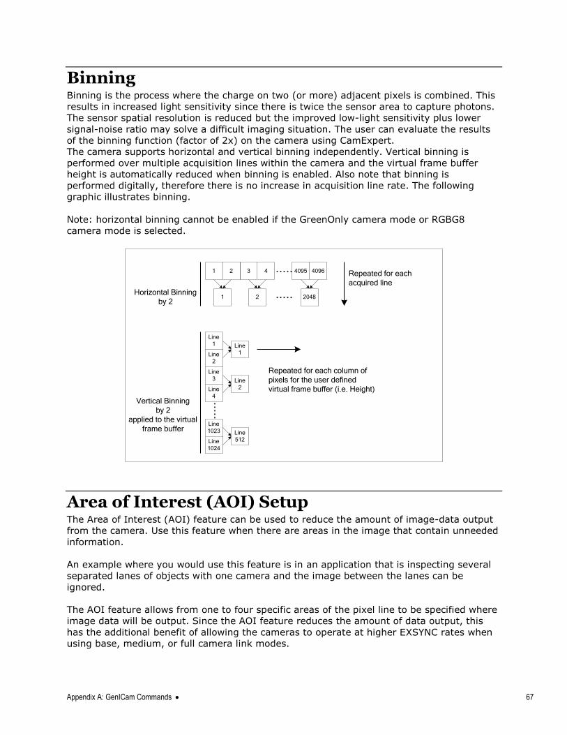
Appendix A: GenICam Commands 67
Binning Binning is the process where the charge on two (or more) adjacent pixels is combined. This
results in increased light sensitivity since there is twice the sensor area to capture photons.
The sensor spatial resolution is reduced but the improved low-light sensitivity plus lower
signal-noise ratio may solve a difficult imaging situation. The user can evaluate the results
of the binning function (factor of 2x) on the camera using CamExpert.
The camera supports horizontal and vertical binning independently. Vertical binning is
performed over multiple acquisition lines within the camera and the virtual frame buffer
height is automatically reduced when binning is enabled. Also note that binning is
performed digitally, therefore there is no increase in acquisition line rate. The following
graphic illustrates binning.
Note: horizontal binning cannot be enabled if the GreenOnly camera mode or RGBG8
camera mode is selected.
1 40964095432
1 2 2048Horizontal Binning
by 2
Line
1
Line
2
Line
3
Line
4
Line
1023
Line
1024
Line
1
Line
2
Line
512
Repeated for each
acquired line
Repeated for each column of
pixels for the user defined
virtual frame buffer (i.e. Height)
Vertical Binning
by 2
applied to the virtual
frame buffer
Area of Interest (AOI) Setup The Area of Interest (AOI) feature can be used to reduce the amount of image-data output
from the camera. Use this feature when there are areas in the image that contain unneeded
information.
An example where you would use this feature is in an application that is inspecting several
separated lanes of objects with one camera and the image between the lanes can be
ignored.
The AOI feature allows from one to four specific areas of the pixel line to be specified where
image data will be output. Since the AOI feature reduces the amount of data output, this
has the additional benefit of allowing the cameras to operate at higher EXSYNC rates when
using base, medium, or full camera link modes.
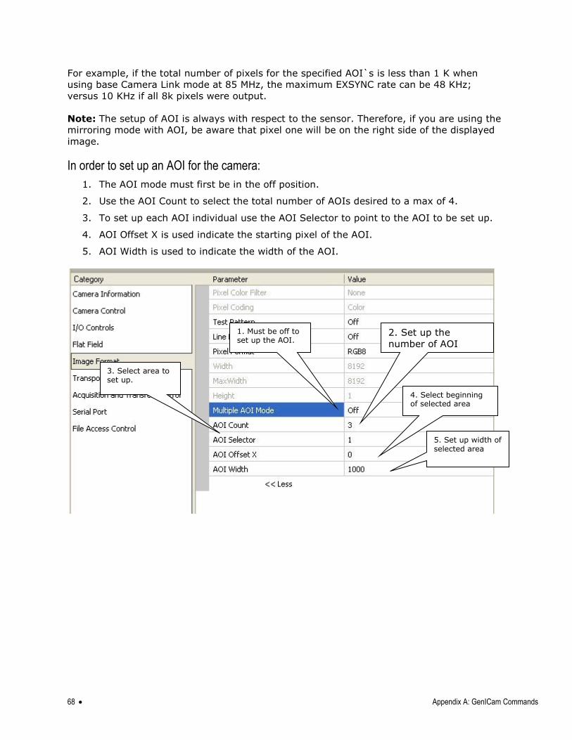
68 Appendix A: GenICam Commands
For example, if the total number of pixels for the specified AOI`s is less than 1 K when
using base Camera Link mode at 85 MHz, the maximum EXSYNC rate can be 48 KHz;
versus 10 KHz if all 8k pixels were output.
Note: The setup of AOI is always with respect to the sensor. Therefore, if you are using the
mirroring mode with AOI, be aware that pixel one will be on the right side of the displayed
image.
In order to set up an AOI for the camera:
1. The AOI mode must first be in the off position.
2. Use the AOI Count to select the total number of AOIs desired to a max of 4.
3. To set up each AOI individual use the AOI Selector to point to the AOI to be set up.
4. AOI Offset X is used indicate the starting pixel of the AOI.
5. AOI Width is used to indicate the width of the AOI.
4. Select beginning of selected area
5. Set up width of selected area
3. Select area to set up.
2. Set up the
number of AOI
desired to max of 4.
1. Must be off to set up the AOI.
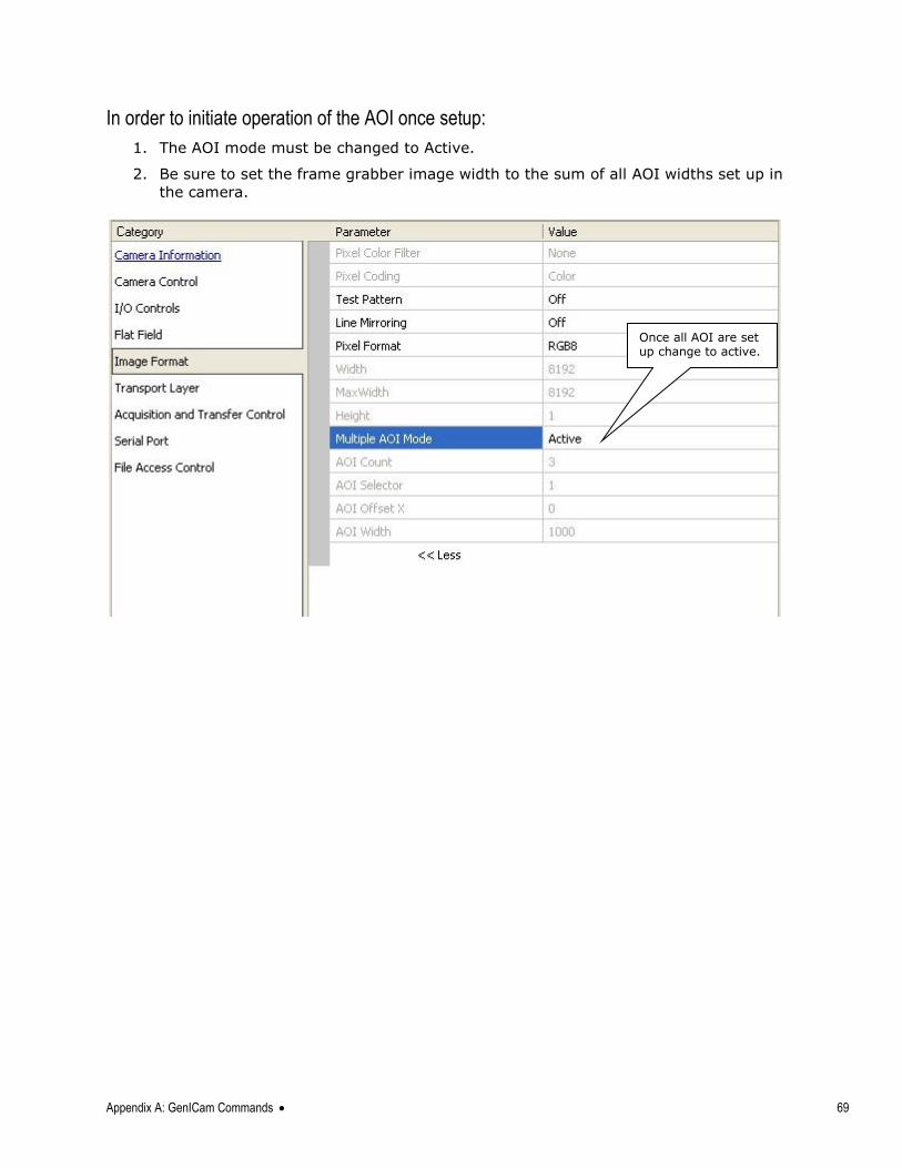
Appendix A: GenICam Commands 69
In order to initiate operation of the AOI once setup:
1. The AOI mode must be changed to Active.
2. Be sure to set the frame grabber image width to the sum of all AOI widths set up in
the camera.
Once all AOI are set up change to active.
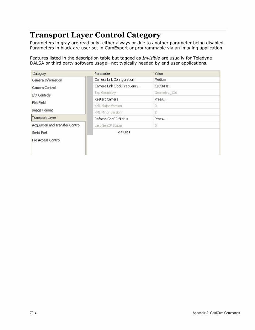
70 Appendix A: GenICam Commands
Transport Layer Control Category Parameters in gray are read only, either always or due to another parameter being disabled.
Parameters in black are user set in CamExpert or programmable via an imaging application.
Features listed in the description table but tagged as Invisible are usually for Teledyne
DALSA or third party software usage—not typically needed by end user applications.
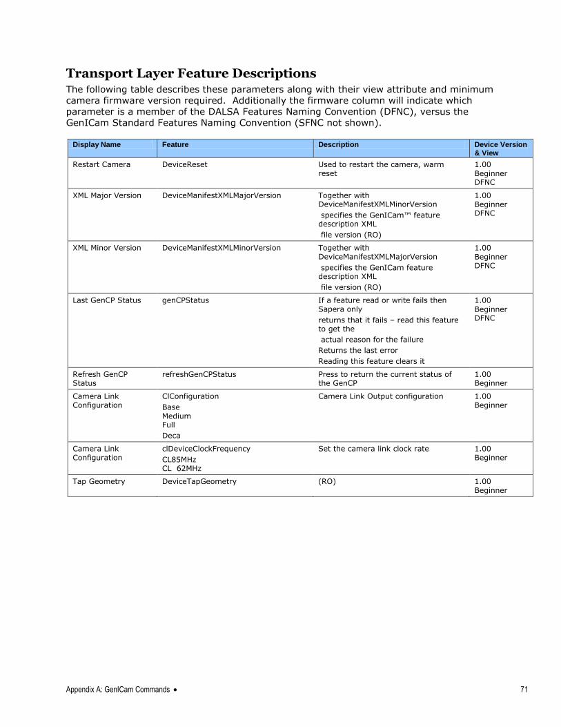
Appendix A: GenICam Commands 71
Transport Layer Feature Descriptions The following table describes these parameters along with their view attribute and minimum
camera firmware version required. Additionally the firmware column will indicate which
parameter is a member of the DALSA Features Naming Convention (DFNC), versus the
GenICam Standard Features Naming Convention (SFNC not shown).
Display Name Feature Description Device Version
& View
Restart Camera
DeviceReset
Used to restart the camera, warm reset
1.00
Beginner DFNC
XML Major Version
DeviceManifestXMLMajorVersion
Together with DeviceManifestXMLMinorVersion
specifies the GenICam™ feature description XML
file version (RO)
1.00 Beginner DFNC
XML Minor Version
DeviceManifestXMLMinorVersion
Together with DeviceManifestXMLMajorVersion
specifies the GenICam feature description XML
file version (RO)
1.00
Beginner DFNC
Last GenCP Status
genCPStatus
If a feature read or write fails then Sapera only
returns that it fails – read this feature to get the
actual reason for the failure
Returns the last error
Reading this feature clears it
1.00
Beginner DFNC
Refresh GenCP Status
refreshGenCPStatus Press to return the current status of the GenCP
1.00 Beginner
Camera Link Configuration
ClConfiguration
Base Medium Full
Deca
Camera Link Output configuration 1.00 Beginner
Camera Link Configuration
clDeviceClockFrequency
CL85MHz CL 62MHz
Set the camera link clock rate 1.00 Beginner
Tap Geometry DeviceTapGeometry (RO) 1.00 Beginner
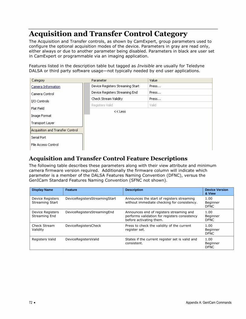
72 Appendix A: GenICam Commands
Acquisition and Transfer Control Category The Acquisition and Transfer controls, as shown by CamExpert, group parameters used to
configure the optional acquisition modes of the device. Parameters in gray are read only,
either always or due to another parameter being disabled. Parameters in black are user set
in CamExpert or programmable via an imaging application.
Features listed in the description table but tagged as Invisible are usually for Teledyne
DALSA or third party software usage—not typically needed by end user applications.
Acquisition and Transfer Control Feature Descriptions The following table describes these parameters along with their view attribute and minimum
camera firmware version required. Additionally the firmware column will indicate which
parameter is a member of the DALSA Features Naming Convention (DFNC), versus the
GenICam Standard Features Naming Convention (SFNC not shown).
Display Name Feature Description Device Version
& View
Device Registers Streaming Start
DeviceRegistersStreamingStart Announces the start of registers streaming without immediate checking for consistency.
1.00
Beginner DFNC
Device Registers Streaming End
DeviceRegistersStreamingEnd Announces end of registers streaming and performs validation for registers consistency before activating them.
1.00 Beginner DFNC
Check Stream Validity
DeviceRegistersCheck Press to check the validity of the current register set.
1.00
Beginner DFNC
Registers Valid DeviceRegistersValid States if the current register set is valid and consistent.
1.00 Beginner DFNC
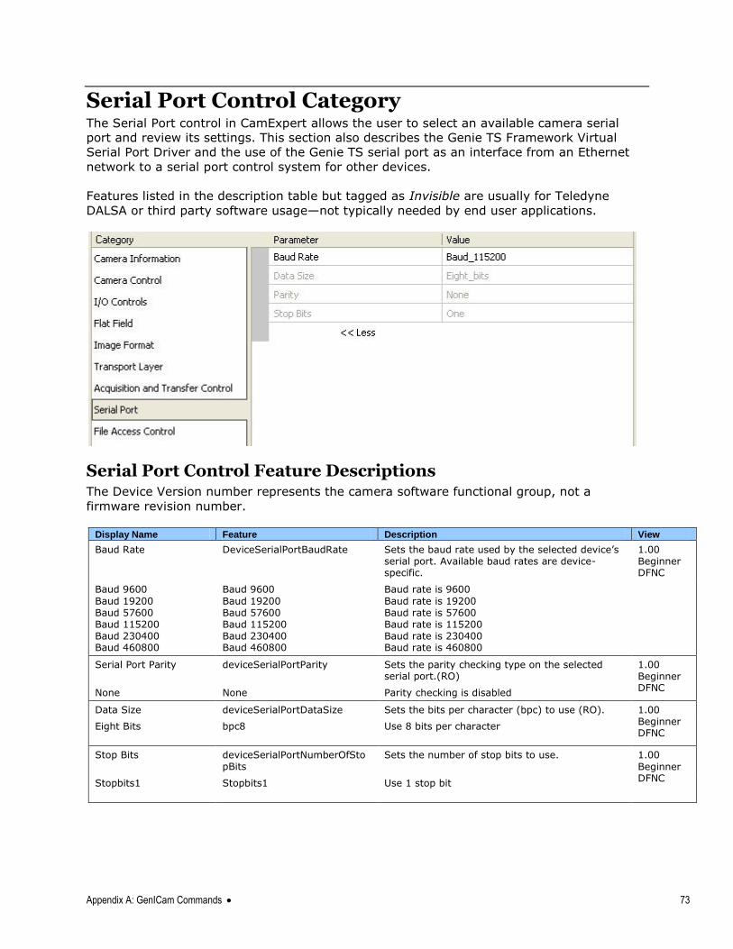
Appendix A: GenICam Commands 73
Serial Port Control Category The Serial Port control in CamExpert allows the user to select an available camera serial
port and review its settings. This section also describes the Genie TS Framework Virtual
Serial Port Driver and the use of the Genie TS serial port as an interface from an Ethernet
network to a serial port control system for other devices.
Features listed in the description table but tagged as Invisible are usually for Teledyne
DALSA or third party software usage—not typically needed by end user applications.
Serial Port Control Feature Descriptions The Device Version number represents the camera software functional group, not a
firmware revision number.
Display Name Feature Description View
Baud Rate DeviceSerialPortBaudRate Sets the baud rate used by the selected device‘s serial port. Available baud rates are device-specific.
1.00 Beginner DFNC
Baud 9600
Baud 19200 Baud 57600 Baud 115200 Baud 230400 Baud 460800
Baud 9600
Baud 19200 Baud 57600 Baud 115200 Baud 230400 Baud 460800
Baud rate is 9600
Baud rate is 19200 Baud rate is 57600 Baud rate is 115200 Baud rate is 230400 Baud rate is 460800
Serial Port Parity deviceSerialPortParity Sets the parity checking type on the selected serial port.(RO)
1.00 Beginner DFNC
None None Parity checking is disabled
Data Size deviceSerialPortDataSize Sets the bits per character (bpc) to use (RO). 1.00 Beginner DFNC
Eight Bits
bpc8
Use 8 bits per character
Stop Bits deviceSerialPortNumberOfStopBits
Sets the number of stop bits to use. 1.00
Beginner DFNC
Stopbits1
Stopbits1
Use 1 stop bit
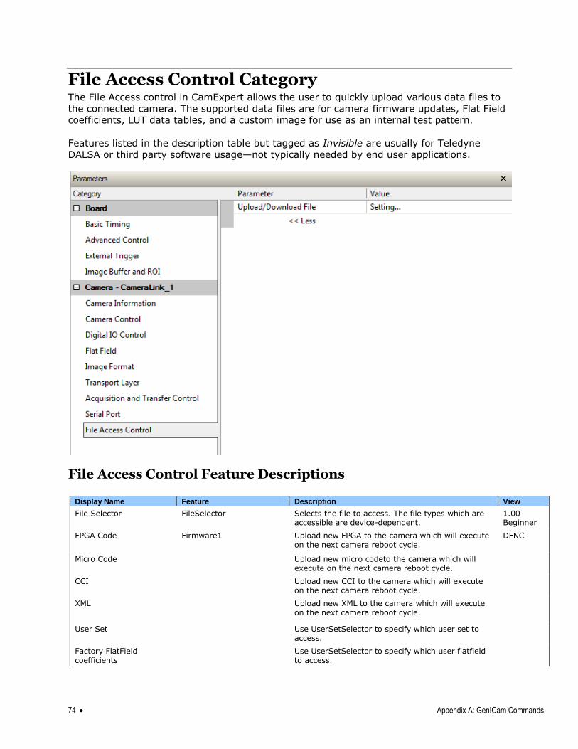
74 Appendix A: GenICam Commands
File Access Control Category The File Access control in CamExpert allows the user to quickly upload various data files to
the connected camera. The supported data files are for camera firmware updates, Flat Field
coefficients, LUT data tables, and a custom image for use as an internal test pattern.
Features listed in the description table but tagged as Invisible are usually for Teledyne
DALSA or third party software usage—not typically needed by end user applications.
File Access Control Feature Descriptions
Display Name Feature Description View
File Selector FileSelector Selects the file to access. The file types which are accessible are device-dependent.
1.00 Beginner
FPGA Code Firmware1 Upload new FPGA to the camera which will execute on the next camera reboot cycle.
DFNC
Micro Code Upload new micro codeto the camera which will execute on the next camera reboot cycle.
CCI Upload new CCI to the camera which will execute on the next camera reboot cycle.
XML Upload new XML to the camera which will execute on the next camera reboot cycle.
User Set Use UserSetSelector to specify which user set to access.
Factory FlatField coefficients
Use UserSetSelector to specify which user flatfield to access.
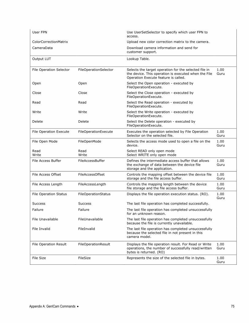
Appendix A: GenICam Commands 75
User FPN Use UserSetSelector to specify which user FPN to access.
ColorCorrectionMatrix Upload new color correction matrix to the camera.
CameraData Download camera information and send for customer support.
Output LUT Lookup Table.
File Operation Selector FileOperationSelector Selects the target operation for the selected file in
the device. This operation is executed when the File Operation Execute feature is called.
1.00 Guru
Open Open Select the Open operation - executed by FileOperationExecute.
Close Close Select the Close operation - executed by FileOperationExecute.
Read Read Select the Read operation - executed by FileOperationExecute.
Write Write Select the Write operation - executed by FileOperationExecute.
Delete Delete Select the Delete operation - executed by FileOperationExecute.
File Operation Execute FileOperationExecute Executes the operation selected by File Operation Selector on the selected file.
1.00 Guru
File Open Mode FileOpenMode Selects the access mode used to open a file on the device.
1.00 Guru
Read Write
Read Write
Select READ only open mode Select WRITE only open mode
File Access Buffer FileAccessBuffer Defines the intermediate access buffer that allows
the exchange of data between the device file storage and the application.
1.00 Guru
File Access Offset FileAccessOffset Controls the mapping offset between the device file storage and the file access buffer.
1.00 Guru
File Access Length FileAccessLength Controls the mapping length between the device file storage and the file access buffer.
1.00 Guru
File Operation Status FileOperationStatus Displays the file operation execution status. (RO). 1.00 Guru
Success Success The last file operation has completed successfully.
Failure Failure The last file operation has completed unsuccessfully for an unknown reason.
File Unavailable FileUnavailable The last file operation has completed unsuccessfully because the file is currently unavailable.
File Invalid FileInvalid The last file operation has completed unsuccessfully because the selected file in not present in this camera model.
File Operation Result FileOperationResult Displays the file operation result. For Read or Write
operations, the number of successfully read/written bytes is returned. (RO)
1.00 Guru
File Size FileSize Represents the size of the selected file in bytes. 1.00 Guru
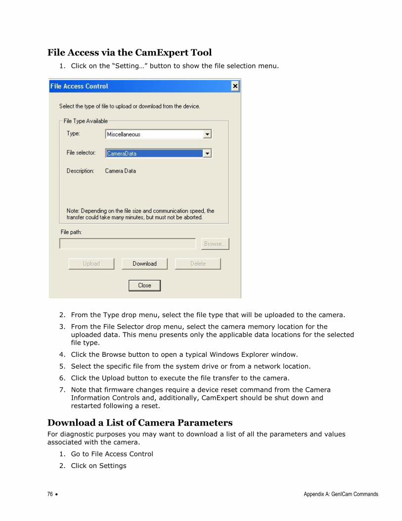
76 Appendix A: GenICam Commands
File Access via the CamExpert Tool
1. Click on the ―Setting…‖ button to show the file selection menu.
2. From the Type drop menu, select the file type that will be uploaded to the camera.
3. From the File Selector drop menu, select the camera memory location for the
uploaded data. This menu presents only the applicable data locations for the selected
file type.
4. Click the Browse button to open a typical Windows Explorer window.
5. Select the specific file from the system drive or from a network location.
6. Click the Upload button to execute the file transfer to the camera.
7. Note that firmware changes require a device reset command from the Camera
Information Controls and, additionally, CamExpert should be shut down and
restarted following a reset.
Download a List of Camera Parameters For diagnostic purposes you may want to download a list of all the parameters and values
associated with the camera.
1. Go to File Access Control
2. Click on Settings
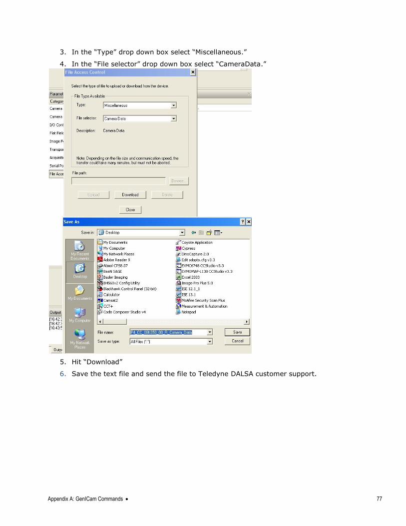
Appendix A: GenICam Commands 77
3. In the ―Type‖ drop down box select ―Miscellaneous.‖
4. In the ―File selector‖ drop down box select ―CameraData.‖
5. Hit ―Download‖
6. Save the text file and send the file to Teledyne DALSA customer support.
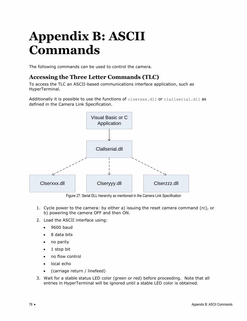
78 Appendix B: ASCII Commands
Appendix B: ASCII Commands The following commands can be used to control the camera.
Accessing the Three Letter Commands (TLC) To access the TLC an ASCII-based communications interface application, such as
HyperTerminal.
Additionally it is possible to use the functions of clserxxx.dll or clallserial.dll as
defined in the Camera Link Specification.
Visual Basic or C
Application
Clallserial.dll
Clserxxx.dll Clseryyy.dll Clserzzz.dll
Figure 27: Serial DLL hierarchy as mentioned in the Camera Link Specification
1. Cycle power to the camera: by either a) issuing the reset camera command (rc), or
b) powering the camera OFF and then ON.
2. Load the ASCII interface using:
9600 baud
8 data bits
no parity
1 stop bit
no flow control
local echo
(carriage return / linefeed)
3. Wait for a stable status LED color (green or red) before proceeding. Note that all
entries in HyperTerminal will be ignored until a stable LED color is obtained.
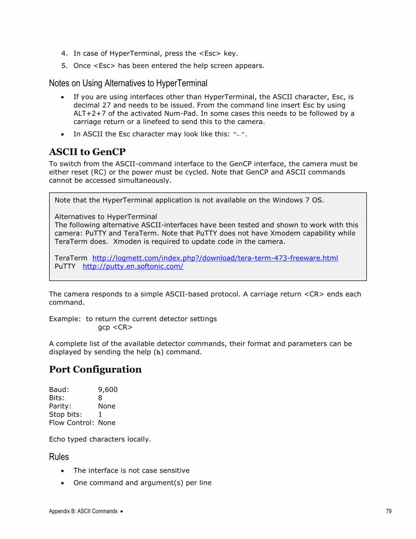
Appendix B: ASCII Commands 79
4. In case of HyperTerminal, press the <Esc> key.
5. Once <Esc> has been entered the help screen appears.
Notes on Using Alternatives to HyperTerminal
If you are using interfaces other than HyperTerminal, the ASCII character, Esc, is
decimal 27 and needs to be issued. From the command line insert Esc by using
ALT+2+7 of the activated Num-Pad. In some cases this needs to be followed by a
carriage return or a linefeed to send this to the camera.
In ASCII the Esc character may look like this: “←”.
ASCII to GenCP To switch from the ASCII-command interface to the GenCP interface, the camera must be
either reset (RC) or the power must be cycled. Note that GenCP and ASCII commands
cannot be accessed simultaneously.
The camera responds to a simple ASCII-based protocol. A carriage return <CR> ends each
command.
Example: to return the current detector settings
gcp <CR>
A complete list of the available detector commands, their format and parameters can be
displayed by sending the help (h) command.
Port Configuration
Baud: 9,600
Bits: 8
Parity: None
Stop bits: 1
Flow Control: None
Echo typed characters locally.
Rules
The interface is not case sensitive
One command and argument(s) per line
Note that the HyperTerminal application is not available on the Windows 7 OS.
Alternatives to HyperTerminal
The following alternative ASCII-interfaces have been tested and shown to work with this
camera: PuTTY and TeraTerm. Note that PuTTY does not have Xmodem capability while
TeraTerm does. Xmoden is required to update code in the camera.
TeraTerm http://logmett.com/index.php?/download/tera-term-473-freeware.html
PuTTY http://putty.en.softonic.com/
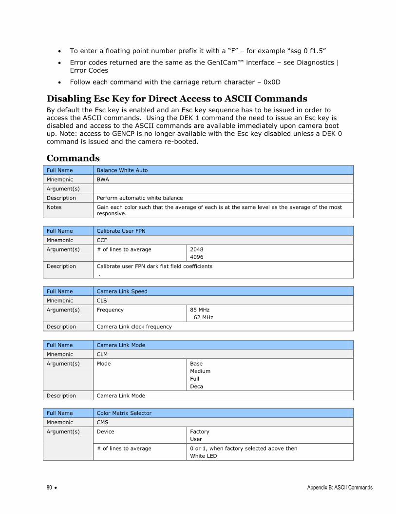
80 Appendix B: ASCII Commands
To enter a floating point number prefix it with a ―F‖ – for example ―ssg 0 f1.5‖
Error codes returned are the same as the GenICam™ interface – see Diagnostics |
Error Codes
Follow each command with the carriage return character – 0x0D
Disabling Esc Key for Direct Access to ASCII Commands By default the Esc key is enabled and an Esc key sequence has to be issued in order to
access the ASCII commands. Using the DEK 1 command the need to issue an Esc key is
disabled and access to the ASCII commands are available immediately upon camera boot
up. Note: access to GENCP is no longer available with the Esc key disabled unless a DEK 0
command is issued and the camera re-booted.
Commands Full Name Balance White Auto
Mnemonic BWA
Argument(s)
Description Perform automatic white balance
Notes Gain each color such that the average of each is at the same level as the average of the most responsive.
Full Name Calibrate User FPN
Mnemonic CCF
Argument(s) # of lines to average 2048
4096
Description Calibrate user FPN dark flat field coefficients
.
Full Name Camera Link Speed
Mnemonic CLS
Argument(s) Frequency 85 MHz
62 MHz
Description Camera Link clock frequency
Full Name Camera Link Mode
Mnemonic CLM
Argument(s) Mode Base
Medium
Full
Deca
Description Camera Link Mode
Full Name Color Matrix Selector
Mnemonic CMS
Argument(s) Device Factory
User
# of lines to average 0 or 1, when factory selected above then
White LED
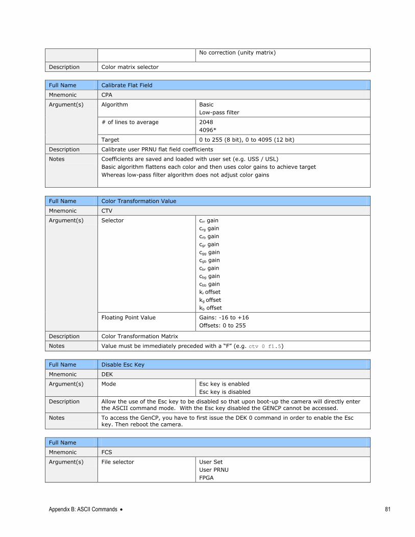
Appendix B: ASCII Commands 81
No correction (unity matrix)
Description Color matrix selector
Full Name Calibrate Flat Field
Mnemonic CPA
Argument(s) Algorithm Basic
Low-pass filter
# of lines to average 2048
4096*
Target 0 to 255 (8 bit), 0 to 4095 (12 bit)
Description Calibrate user PRNU flat field coefficients
Notes Coefficients are saved and loaded with user set (e.g. USS / USL)
Basic algorithm flattens each color and then uses color gains to achieve target
Whereas low-pass filter algorithm does not adjust color gains
Full Name Color Transformation Value
Mnemonic CTV
Argument(s) Selector crr gain
crg gain
crb gain
cgr gain
cgg gain
cgb gain
cbr gain
cbg gain
cbb gain
kr offset
kg offset
kb offset
Floating Point Value Gains: -16 to +16
Offsets: 0 to 255
Description Color Transformation Matrix
Notes Value must be immediately preceded with a ―F‖ (e.g. ctv 0 f1.5)
Full Name Disable Esc Key
Mnemonic DEK
Argument(s) Mode Esc key is enabled
Esc key is disabled
Description Allow the use of the Esc key to be disabled so that upon boot-up the camera will directly enter the ASCII command mode. With the Esc key disabled the GENCP cannot be accessed.
Notes To access the GenCP, you have to first issue the DEK 0 command in order to enable the Esc key. Then reboot the camera.
Full Name
Mnemonic FCS
Argument(s) File selector User Set
User PRNU
FPGA
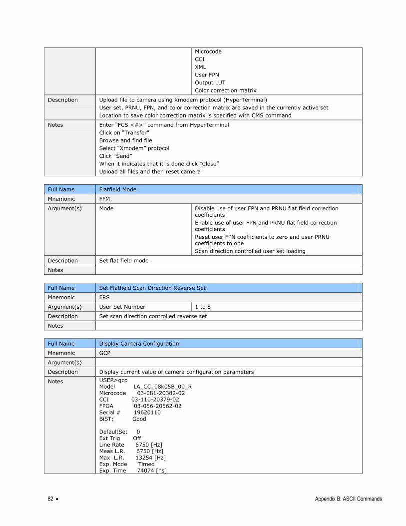
82 Appendix B: ASCII Commands
Microcode
CCI
XML
User FPN
Output LUT
Color correction matrix
Description Upload file to camera using Xmodem protocol (HyperTerminal)
User set, PRNU, FPN, and color correction matrix are saved in the currently active set
Location to save color correction matrix is specified with CMS command
Notes Enter ―FCS <#>‖ command from HyperTerminal
Click on ―Transfer‖
Browse and find file
Select ―Xmodem‖ protocol
Click ―Send‖
When it indicates that it is done click ―Close‖
Upload all files and then reset camera
Full Name Flatfield Mode
Mnemonic FFM
Argument(s) Mode Disable use of user FPN and PRNU flat field correction coefficients
Enable use of user FPN and PRNU flat field correction coefficients
Reset user FPN coefficients to zero and user PRNU coefficients to one
Scan direction controlled user set loading
Description Set flat field mode
Notes
Full Name Set Flatfield Scan Direction Reverse Set
Mnemonic FRS
Argument(s) User Set Number 1 to 8
Description Set scan direction controlled reverse set
Notes
Full Name Display Camera Configuration
Mnemonic GCP
Argument(s)
Description Display current value of camera configuration parameters
Notes USER>gcp Model LA_CC_08k05B_00_R Microcode 03-081-20382-02 CCI 03-110-20379-02 FPGA 03-056-20562-02 Serial # 19620110 BiST: Good DefaultSet 0 Ext Trig Off Line Rate 6750 [Hz] Meas L.R. 6750 [Hz] Max L.R. 13254 [Hz] Exp. Mode Timed Exp. Time 74074 [ns]
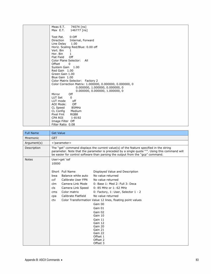
Appendix B: ASCII Commands 83
Meas E.T. 74074 [ns] Max E.T. 146777 [ns] Test Pat. 0:Off Direction Internal, Forward Line Delay 1.00 Horiz. Scaling Red/Blue: 0.00 off Vert. Bin 1 Hor. Bin 1 Flat Field Off Color Plane Selector: All Offset 0 System Gain 1.00 Red Gain 1.00 Green Gain 1.00 Blue Gain 1.00
Color Matrix Selector: Factory 2 Color Correction Matrix: 1.000000, 0.000000, 0.000000, 0 0.000000, 1.000000, 0.000000, 0 0.000000, 0.000000, 1.000000, 0 Mirror Off LUT Set 0 LUT mode off AOI Mode: Off CL Speed 85MHz CL Config Medium Pixel Fmt RGB8 CPA ROI 1-8192 Image Filter Off Filter Ratio 0.08
Full Name Get Value
Mnemonic GET
Argument(s) <‘parameter>
Description The ―get‖ command displays the current value(s) of the feature specified in the string
parameter. Note that the parameter is preceded by a single quote ―‘‖. Using this command will be easier for control software than parsing the output from the ―gcp‖ command.
Notes User>get ‗ssf
10000
Short Full Name Displayed Value and Description
bwa Balance white auto No value returned
ccf Calibrate User FPN No value returned
clm Camera Link Mode 0: Base 1: Med 2: Full 3: Deca
cls Camera Link Speed 0: 85 MHz or 1: 62 MHz
cms Color matrix 0: Factory, 1: User, Selector 1 - 2
cpa Calibrate Flatfield No value returned
ctv Color Transformation Value 12 lines, floating point values
Gain 00
Gain 01
Gain 02 Gain 10
Gain 11 Gain 12 Gain 20 Gain 21 Gain 22 Offset 1 Offset 2 Offset 3
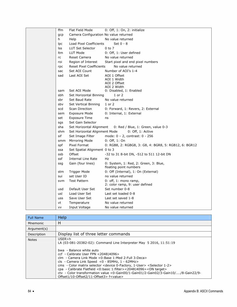
84 Appendix B: ASCII Commands
ffm Flat Field Mode 0: Off, 1: On, 2: initialize
gcp Camera Configuration No value returned
h Help No value returned
lpc Load Pixel Coefficients Set 0 - 8
lss LUT Set Selector 0 to 7
ltm LUT Mode 0: Off, 1: User defined
rc Reset Camera No value returned
roi Region of Interest Start pixel and end pixel numbers
rpc Reset Pixel Coefficients No value returned
sac Set AOI Count Number of AOI‘s 1-4
sad Last AOI Set AOI 1 Offset AOI 1 Width AOI 2 Offset AOI 2 Width sam Set AOI Mode 0: Disabled, 1: Enabled
sbh Set Horizontal Binning 1 or 2
sbr Set Baud Rate No value returned
sbv Set Vertical Binning 1 or 2
scd Scan Direction 0: Forward, 1: Revers, 2: External
sem Exposure Mode 0: Internal, 1: External
set Exposure Time ns
sgs Set Gain Selector
sha Set Horizontal Alignment 0: Red / Blue, 1: Green, value 0-3
shm Set Horizontal Alignment Mode 0: Off, 1: Active
sif Set Image Filter mode: 0 – 2, contrast: 0 - 256
smm Mirroring Mode 0: Off, 1: On
spf Pixel Format 0: RGB8, 2: RGBG8, 3: G8, 4: BGR8, 5: RGB12, 6: BGR12
ssa Set Spatial Alignment 0 to 3
ssb Offset -32 to 31 8-bit DN, -512 to 511 12-bit DN
ssf Internal Line Rate Hz
ssg Gain (four lines) 0: System, 1: Red, 2: Green, 3: Blue, floating point numbers
stm Trigger Mode 0: Off (Internal), 1: On (External)
sui set User ID no value returned
svm Test Pattern 0: off, 1: mono ramp, 2: color ramp, 9: user defined
usd Default User Set Set number 0-8
usl Load User Set Last set loaded 0-8
uss Save User Set Last set saved 1-8
vt Temperature No value returned
vv Input Voltage No value returned
Full Name Help
Mnemonic H
Argument(s)
Description Display list of three letter commands
Notes USER>h LA (03-081-20382-02): Command Line Interpreter May 5 2016, 11:51:19 bwa - Balance white auto ccf - Calibrate User FPN <2048|4096> clm - Camera Link Mode <0:Base 1:Med 2:Full 3:Deca> cls - Camera Link Speed <0 - 85MHz, 1 - 62MHz> cms - Color matrix selector <device 0-Factory, 1-User> <Selector 1-2> cpa - Calibrate Flatfield <0:basic 1:filter><2048|4096><DN target> ctv - Color transformation value <0-Gain00/1-Gain01/2-Gain02/3-Gain10/..../8-Gain22/9-Offset1/10-Offset2/11-Offset3> f<value>
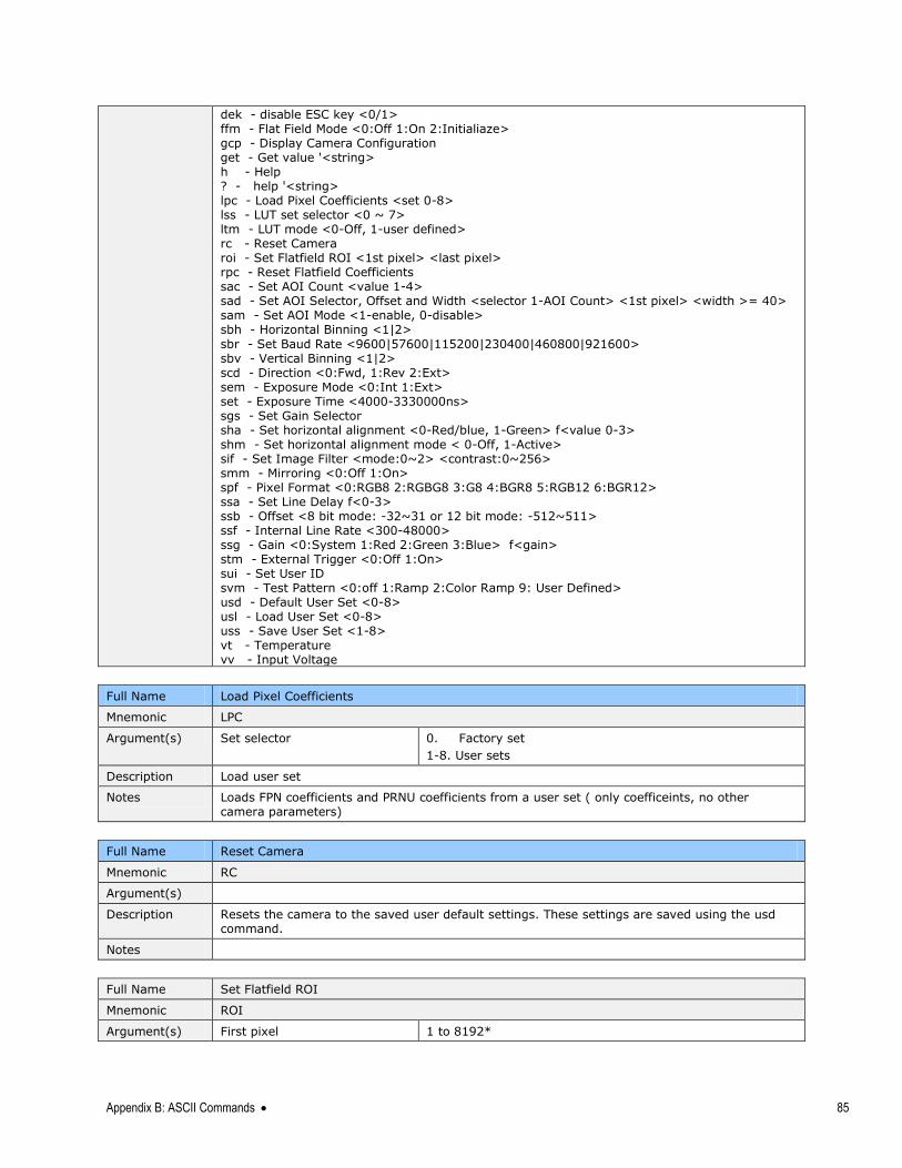
Appendix B: ASCII Commands 85
dek - disable ESC key <0/1> ffm - Flat Field Mode <0:Off 1:On 2:Initialiaze> gcp - Display Camera Configuration get - Get value '<string> h - Help ? - help '<string> lpc - Load Pixel Coefficients <set 0-8> lss - LUT set selector <0 ~ 7> ltm - LUT mode <0-Off, 1-user defined> rc - Reset Camera roi - Set Flatfield ROI <1st pixel> <last pixel> rpc - Reset Flatfield Coefficients sac - Set AOI Count <value 1-4> sad - Set AOI Selector, Offset and Width <selector 1-AOI Count> <1st pixel> <width >= 40> sam - Set AOI Mode <1-enable, 0-disable> sbh - Horizontal Binning <1|2>
sbr - Set Baud Rate <9600|57600|115200|230400|460800|921600> sbv - Vertical Binning <1|2> scd - Direction <0:Fwd, 1:Rev 2:Ext> sem - Exposure Mode <0:Int 1:Ext> set - Exposure Time <4000-3330000ns> sgs - Set Gain Selector sha - Set horizontal alignment <0-Red/blue, 1-Green> f<value 0-3> shm - Set horizontal alignment mode < 0-Off, 1-Active> sif - Set Image Filter <mode:0~2> <contrast:0~256> smm - Mirroring <0:Off 1:On> spf - Pixel Format <0:RGB8 2:RGBG8 3:G8 4:BGR8 5:RGB12 6:BGR12> ssa - Set Line Delay f<0-3> ssb - Offset <8 bit mode: -32~31 or 12 bit mode: -512~511> ssf - Internal Line Rate <300-48000> ssg - Gain <0:System 1:Red 2:Green 3:Blue> f<gain> stm - External Trigger <0:Off 1:On> sui - Set User ID svm - Test Pattern <0:off 1:Ramp 2:Color Ramp 9: User Defined> usd - Default User Set <0-8> usl - Load User Set <0-8> uss - Save User Set <1-8> vt - Temperature vv - Input Voltage
Full Name Load Pixel Coefficients
Mnemonic LPC
Argument(s) Set selector 0. Factory set 1-8. User sets
Description Load user set
Notes Loads FPN coefficients and PRNU coefficients from a user set ( only coefficeints, no other camera parameters)
Full Name Reset Camera
Mnemonic RC
Argument(s)
Description Resets the camera to the saved user default settings. These settings are saved using the usd command.
Notes
Full Name Set Flatfield ROI
Mnemonic ROI
Argument(s) First pixel 1 to 8192*
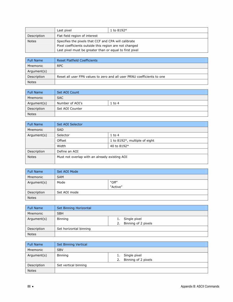
86 Appendix B: ASCII Commands
Last pixel 1 to 8192*
Description Flat field region of interest
Notes Specifies the pixels that CCF and CPA will calibrate
Pixel coefficients outside this region are not changed
Last pixel must be greater than or equal to first pixel
Full Name Reset Flatfield Coefficients
Mnemonic RPC
Argument(s)
Description Reset all user FPN values to zero and all user PRNU coefficients to one
Notes
Full Name Set AOI Count
Mnemonic SAC
Argument(s) Number of AOI‘s 1 to 4
Description Set AOI Counter
Notes
Full Name Set AOI Selector
Mnemonic SAD
Argument(s) Selector 1 to 4
Offset 1 to 8192*, multiple of eight
Width 40 to 8192*
Description Define an AOI
Notes Must not overlap with an already existing AOI
Full Name Set AOI Mode
Mnemonic SAM
Argument(s) Mode ―Off‖
―Active‖
Description Set AOI mode
Notes
Full Name Set Binning Horizontal
Mnemonic SBH
Argument(s) Binning 1. Single pixel
2. Binning of 2 pixels
Description Set horizontal binning
Notes
Full Name Set Binning Vertical
Mnemonic SBV
Argument(s) Binning 1. Single pixel
2. Binning of 2 pixels
Description Set vertical binning
Notes
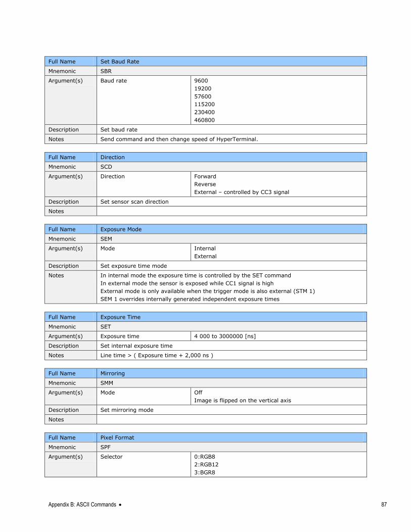
Appendix B: ASCII Commands 87
Full Name Set Baud Rate
Mnemonic SBR
Argument(s) Baud rate 9600
19200
57600
115200
230400
460800
Description Set baud rate
Notes Send command and then change speed of HyperTerminal.
Full Name Direction
Mnemonic SCD
Argument(s) Direction Forward
Reverse
External – controlled by CC3 signal
Description Set sensor scan direction
Notes
Full Name Exposure Mode
Mnemonic SEM
Argument(s) Mode Internal
External
Description Set exposure time mode
Notes In internal mode the exposure time is controlled by the SET command
In external mode the sensor is exposed while CC1 signal is high
External mode is only available when the trigger mode is also external (STM 1)
SEM 1 overrides internally generated independent exposure times
Full Name Exposure Time
Mnemonic SET
Argument(s) Exposure time 4 000 to 3000000 [ns]
Description Set internal exposure time
Notes Line time > ( Exposure time + 2,000 ns )
Full Name Mirroring
Mnemonic SMM
Argument(s) Mode Off
Image is flipped on the vertical axis
Description Set mirroring mode
Notes
Full Name Pixel Format
Mnemonic SPF
Argument(s) Selector 0:RGB8
2:RGB12
3:BGR8
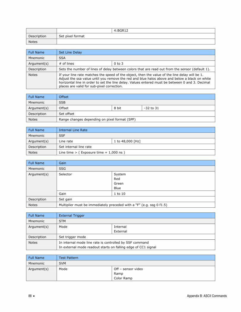
88 Appendix B: ASCII Commands
4:BGR12
Description Set pixel format
Notes
Full Name Set Line Delay
Mnemonic SSA
Argument(s) # of lines 0 to 3
Description Sets the number of lines of delay between colors that are read out from the sensor (default 1).
Notes If your line rate matches the speed of the object, then the value of the line delay will be 1. Adjust the ssa value until you remove the red and blue halos above and below a black on white horizontal line in order to set the line delay. Values entered must be between 0 and 3. Decimal places are valid for sub-pixel correction.
Full Name Offset
Mnemonic SSB
Argument(s) Offset 8 bit -32 to 31
Description Set offset
Notes Range changes depending on pixel format (SPF)
Full Name Internal Line Rate
Mnemonic SSF
Argument(s) Line rate 1 to 48,000 [Hz]
Description Set internal line rate
Notes Line time > ( Exposure time + 1,000 ns )
Full Name Gain
Mnemonic SSG
Argument(s) Selector System
Red
Green
Blue
Gain 1 to 10
Description Set gain
Notes Multiplier must be immediately preceded with a ―F‖ (e.g. ssg 0 f1.5)
Full Name External Trigger
Mnemonic STM
Argument(s) Mode Internal
External
Description Set trigger mode
Notes In internal mode line rate is controlled by SSF command
In external mode readout starts on falling edge of CC1 signal
Full Name Test Pattern
Mnemonic SVM
Argument(s) Mode Off – sensor video
Ramp
Color Ramp
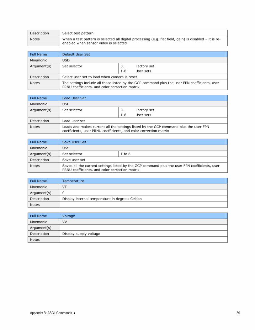
Appendix B: ASCII Commands 89
Description Select test pattern
Notes When a test pattern is selected all digital processing (e.g. flat field, gain) is disabled – it is re-enabled when sensor video is selected
Full Name Default User Set
Mnemonic USD
Argument(s) Set selector 0. Factory set
1-8. User sets
Description Select user set to load when camera is reset
Notes The settings include all those listed by the GCP command plus the user FPN coefficients, user PRNU coefficients, and color correction matrix
Full Name Load User Set
Mnemonic USL
Argument(s) Set selector 0. Factory set
1-8. User sets
Description Load user set
Notes Loads and makes current all the settings listed by the GCP command plus the user FPN coefficients, user PRNU coefficients, and color correction matrix
Full Name Save User Set
Mnemonic USS
Argument(s) Set selector 1 to 8
Description Save user set
Notes Saves all the current settings listed by the GCP command plus the user FPN coefficients, user PRNU coefficients, and color correction matrix
Full Name Temperature
Mnemonic VT
Argument(s) 0
Description Display internal temperature in degrees Celsius
Notes
Full Name Voltage
Mnemonic VV
Argument(s)
Description Display supply voltage
Notes
90 Appendix C: Quick Setup and Image Acquisition
Appendix C: Quick Setup and Image Acquisition If you are familiar with the operation of Camera Link cameras and have an understanding of
imaging fundamentals, the following steps will show you how to quickly set up this camera
and begin acquiring images.
1. On Power-Up The Linea-8K color camera has been calibrated and configured at the factory to be ready for
your evaluation when first powered up. The default conditions are set as follows:
System gain is set to the lowest value of one.
Flat field calibration is not active as this feature is dependent on your light source
and lens.
Line rate and exposure time are set to for internal generation by the camera.
White balance is set for white LEDs.
Camera Link mode is set to the standard RGB medium mode which allows operation
of up to 20 KHz line rate. The camera will run at up to a 34 KHz line rate using
Camera Link Deca mode, but it may be easier to start your evaluation using the
medium mode. Set your Camera Link frame grabber up to receive the standard RGB
medium mode.
2. Communicating with the Camera
The Linea-8K color camera is designed to power up with a GenIcam-compliant
interface.
CamExpert provides an easy-to-use GUI that can be used to set up and evaluate the
camera.
The camera also comes with Teledyne DALSA‘s three letter command (TLC) interface
option, which can be accessed using a suitable terminal program such as
HyperTerminal™.
If you want to use the TLC interface, press the ‗Esc‘ key while using a terminal
program and after the LED indicator on the camera turns green. Note that the
camera defaults to 9.6 KBaud when first powered up.
On receiving the ‗Esc‘ character, the camera will output a list of the available TLC
commands. You can then proceed to enter TLC commands as required.
Enter ‗h‘ at any time to get the list of commands from the camera.
Enter the ‗gcp‘ command at any time to get the current setup conditions of the
camera.
3. Setting Up Your Optical Configuration
Appendix C: Quick Setup and Image Acquisition 91
Typically, the first thing you want to do is to evaluate the camera‘s image quality under
operating conditions similar to those that you are likely to use in your application. In order
to do this, take the following steps:
The illumination, lens magnification, and focus should be set up as per you
application.
Getting the magnification right is best accomplished by setting the object-to-sensor
distance. Use the formula lens focal length x (2 + 1/magnification + magnification)
to calculate this distance. Magnification equals the sensor pixel size (7.05 µm) /
(your object pixel size in um).
The approximate location of the sensor position is at the first groove in the side of
the case, back from the front face.
4. Camera Timing & Control It is easiest and quickest to evaluate the camera using the internal timing setups for line
rate and exposure time.
Since we recommend starting with Camera Link medium mode, set a suitable line
rate less than 20 KHz, using the ‗ssf‘ command.
If this line rate is too slow for your application, you will get a compressed image in
the scan direction. This should not be a problem for a basic evaluation.
You can set the exposure time using the ‗set‘ command. Ensure that the exposure
time period is not greater than the period of the line rate minus 1.5 µsec.
The camera will indicate an error if you select an exposure time that is too long. The
minimum exposure time is 8 µsec.
Set your camera direction using the ‗scd‘ command. Refer to the Camera Direction
Control diagram in this manual for a definition of ‗forward‘ and ‗reverse‘.
5. Acquiring an Image You can now begin imaging. Unless you have an application employing lots of light, the
image is likely to be too dark.
Use the system gain to adjust the camera output to achieve the desired response.
The system gain range is from 1x to 10x.
Once you have a suitable response, you can now focus the lens.
If you are using white LEDs, your image will have reasonable color reproduction.
The image may be darker at the edges due to lens vignetting, but this will be
improved once the camera is calibrated.
Calibration is performed using a white reference where your object is normally
located.
o Use a white material that has no texture, such as a non glossy plastic.
o If you must use white paper, make sure it is moving during the calibration
process. If you do not do this, your image will have vertical stripes.
Calibration is easily performed using the TLC ‗cpa‘ command.
The cpa command has two parameters.
92
o The first is the number of lines you want to average over. Use a value of 8192
to achieve the best average.
o The second is the eight bit target value you want for all three colors after
calibration.
The cpa command takes several seconds to complete. The slower the line rate, the
longer it will take.
On completion of the ‗cpa‘ command, you should see an image from the camera that
is white balanced with all three colors at the target level you set.
You are now ready to evaluate the image quality of the camera under your operating
conditions.
6. Improving Your Color Image The color response of the camera is quite good even when using white LED‘s and even
without color correction. The camera has a factory set white LED color correction matrix
that can be selected to improve color response for those using white LED‘s. If you are using
a different light source, a suitable color correction matrix can be downloaded to the camera.
A software tool to generate this is available with the Sapera processing applications, which
can be downloaded from the Teledyne DALSA web site (60 day free trial). You will require a
MacBeth© chart with 4 x 6 color elements that you can scan past the camera to complete
the generation of the matrix.
Contact Teledyne DALSA‘s technical support for further details.
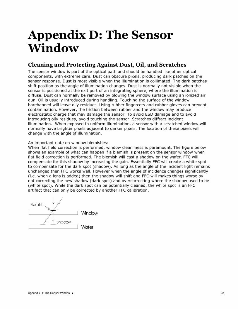
Appendix D: The Sensor Window 93
Appendix D: The Sensor Window
Cleaning and Protecting Against Dust, Oil, and Scratches The sensor window is part of the optical path and should be handled like other optical
components, with extreme care. Dust can obscure pixels, producing dark patches on the
sensor response. Dust is most visible when the illumination is collimated. The dark patches
shift position as the angle of illumination changes. Dust is normally not visible when the
sensor is positioned at the exit port of an integrating sphere, where the illumination is
diffuse. Dust can normally be removed by blowing the window surface using an ionized air
gun. Oil is usually introduced during handling. Touching the surface of the window
barehanded will leave oily residues. Using rubber fingercots and rubber gloves can prevent
contamination. However, the friction between rubber and the window may produce
electrostatic charge that may damage the sensor. To avoid ESD damage and to avoid
introducing oily residues, avoid touching the sensor. Scratches diffract incident
illumination. When exposed to uniform illumination, a sensor with a scratched window will
normally have brighter pixels adjacent to darker pixels. The location of these pixels will
change with the angle of illumination.
An important note on window blemishes:
When flat field correction is performed, window cleanliness is paramount. The figure below
shows an example of what can happen if a blemish is present on the sensor window when
flat field correction is performed. The blemish will cast a shadow on the wafer. FFC will
compensate for this shadow by increasing the gain. Essentially FFC will create a white spot
to compensate for the dark spot (shadow). As long as the angle of the incident light remains
unchanged then FFC works well. However when the angle of incidence changes significantly
(i.e. when a lens is added) then the shadow will shift and FFC will makes things worse by
not correcting the new shadow (dark spot) and overcorrecting where the shadow used to be
(white spot). While the dark spot can be potentially cleaned, the white spot is an FFC
artifact that can only be corrected by another FFC calibration.
94 Appendix D: The Sensor Window
Cleaning the Sensor Window
Recommended Equipment Glass cleaning station with microscope within clean room.
Ionized air gun
Ionized air flood system, foot operated.
Swabs
Single drop bottle
E2 (Eclipse optic cleaning system)
Procedure Use localized ionized air flow on to the glass during sensor cleaning.
Blow off mobile contamination using an ionized air gun.
Place the sensor under the microscope at a magnification of 5x to determine the location of any remaining contamination.
Clean the contamination on the sensor using one drop of E2 on a
swab.
Wipe the swab from left to right (or right to left but only in one
direction). Do this in an overlapping pattern, turning the swab after
the first wipe and with each subsequent wipe. Avoid swiping back and
forth with the same swab in order to ensure that particles are removed
and not simply transferred to a new location on the sensor window. This procedure requires you to use multiple swabs.
Discard the swab after both sides of the swab have been used once.
Repeat until there is no visible contamination present.

EMC Declaration of Conformity 95
EMC Declaration of Conformity We:
Teledyne DALSA inc.
605 McMurray Road,
Waterloo, Ontario, Canada,
N2V 2E9
Declare under sole legal responsibility that the following products conform to the protection
requirements of council directive 2004/108/EC (2014/30/EU after April 2016) on the
approximation of the laws of member states relating to electromagnetic compatibility and
are CE-marked accordingly:
LA-CC-04K05B-00-R and LA-CC-08K05B-00-R
The products to which this declaration relates are in conformity with the following relevant
harmonized standards, the reference numbers of which have been published in the Official
Journal of the European Communities:
EN55032 (2012) Electromagnetic compatibility of multimedia equipment — Emission requirements
EN55011 (2009) with A1(2010)
Industrial, scientific and medical equipment — Radio-frequency disturbance characteristics — Limits and methods of measurement
EN 61326-1 (2013)
Electrical equipment for measurement, control and laboratory use — EMC requirements — Part 1: General requirements
EN 55024 (2010)
Information technology equipment — Immunity characteristics — Limits and methods of measurement
Further declare under our sole legal responsibility that the product listed also conforms to
the following international standards:
CFR 47 part 15 (2008), subpart B, for a class A product. Limits for digital devices
ICES-003 Information Technology Equipment (ITE) — Limits and Methods of Measurement
CISPR 11 Industrial, scientific and medical equipment - Radio-frequency disturbance characteristics - Limits and methods of measurement
CISPR 32 Electromagnetic compatibility of multimedia equipment - Emission requirements
Note: this product is intended to be a component of a larger system.
Waterloo, Canada May 6, 2016
Location Date Hank Helmond.
Director, Quality Assurance

96 Revision History
Revision History
Revision Change Description Revision Date
00 Initial release. May 30, 2016
01 4K model description and specifications added. November 3, 2016
02 Environmental Specs, page 8
Flash memory size table, page 8
CC1 signal description—notes added: keep signal low when idle, exposure time at or under 3,000 µs, page 19.
RGB8 CL Full timing added, descriptions + timing diagram, page 21
Hirose power connector diagram revised, page 29.
March 10, 2017
Index 97
Index
B
baud rate, 45 Binning, 66
black level control, 44
C
calibration, 47 flat field, 49
process chain, 47
camera control signals, 19 camera information, 36 camera interfacing tool, 32 Camera Link
cables, 27
configurations, 39
input signals, 27
outputs, 28
Camera Link connector, 17 camera state LED, 29
CamExpert, 33 cleaning
sensor window, 93
clock signals, 28 connectors, 17
Camera Link, 17
power, 28
D
data bus, 28 direction
sensor shift, 13
web movement, 13
direction control, 46
E
environmental specifications, 8
exposure control, 39
external frame rate,
programmable exposure time,
41
externally controlled, 41
internally controlled, 40
exposure modes descriptions of, 40
exposure time set, 44
EXSYNC, 27
F
factory settings, 36
G
Gain control, 44
grounding instructions, 17
GUI CamExpert, 33
overview, 31
H
horizontal and vertical binning, 66
humidity storage and operation, 8
I
image acquisition, 40 input/output, 17
interface mechanical, 7
L
LED definitions, 29
low-light sensitivity, 66
M
mean time between failures (MTBF), 8
mechanical camera, 14
specifications, 7
MTBF, 8
P
performance specifications, 7
pixel format, 45 power
connector, 28
connectors, 28
98 Index
guidelines, 28
pinout, 28
precautions, 5
Q
quantum efficiency graph, 9
R
rebooting, 46
requirements PC, 15
responsivity graph, 9
revision history, 95
S
safety, 5 Sapera, 32 sensor controls, 54, 58, 62,
71 settings
current, 38
default, 39
factory, 36, 39
loading, 37
saving, 37
user, 38
setup overview, 15
shift direction, 13
size image, 44
spatial resolution, 66 specifications
mechanical, 7
performance, 7
storage temperature, 8
T
temperature verify, 37
test patterns, 35
trigger modes, 39
V
voltage verify, 37