Embed Size (px)
Citation preview
Line manager VAMP 259for distance and line differential protection
vZ3
Z1
Z2Z4
Z5
X
R
2
Line Manager VAMP 259
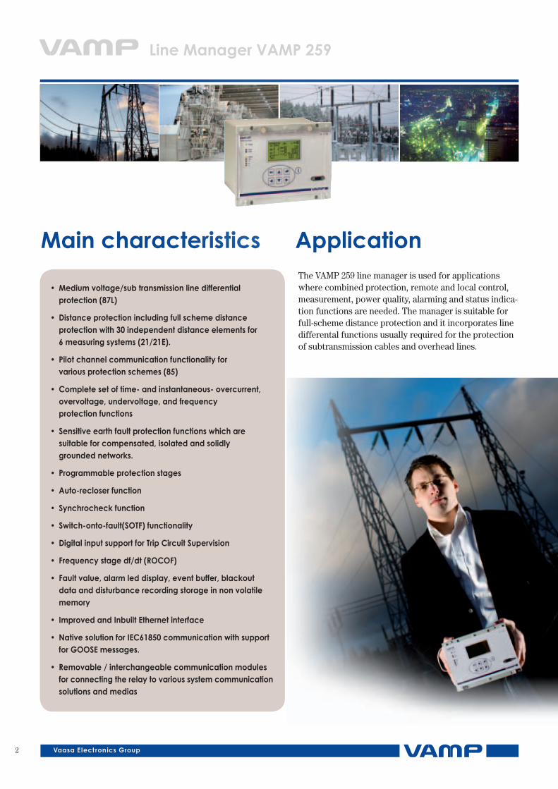
Main characteristics ApplicationThe VAMP 259 line manager is used for applications where combined protection, remote and local control, measurement, power quality, alarming and status indica-tion functions are needed. The manager is suitable for full-scheme distance protection and it incorporates line differental functions usually required for the protection of subtransmission cables and overhead lines.
• Mediumvoltage/subtransmissionlinedifferential protection (87L)
• Distanceprotectionincludingfullschemedistance protection with 30 independent distance elements for 6measuringsystems(21/21E).
• Pilotchannelcommunicationfunctionalityfor variousprotectionschemes(85)
• Completesetoftime-andinstantaneous-overcurrent, overvoltage,undervoltage,andfrequency protectionfunctions
• Sensitiveearthfaultprotectionfunctionswhichare suitableforcompensated,isolatedandsolidly groundednetworks.
• Programmableprotectionstages
• Auto-recloserfunction
• Synchrocheckfunction
• Switch-onto-fault(SOTF)functionality
• DigitalinputsupportforTripCircuitSupervision
• Frequencystagedf/dt(ROCOF)
• Faultvalue,alarmleddisplay,eventbuffer,blackout dataanddisturbancerecordingstorageinnonvolatile memory
• ImprovedandInbuiltEthernetinterface
• NativesolutionforIEC61850communicationwithsupport forGOOSEmessages.
• Removable/interchangeablecommunicationmodules forconnectingtherelaytovarioussystemcommunication solutionsandmedias
3
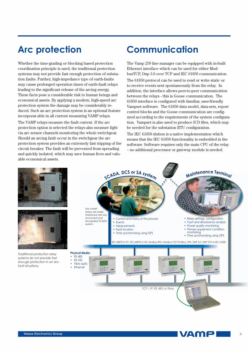
Whether the time-grading or blocking based protection coordination principle is used, the traditional protection systems may not provide fast enough protection of substa-tion faults. Further, high-impedance type of earth-faults may cause prolonged operation times of earth-fault relays leading to the significant release of the arcing energy. These facts pose a considerable risk to human beings and economical assets. By applying a modern, high-speed arc protection system the damage may be considerably re-duced. Such an arc protection system is an optional feature incorporat-able in all current measuring VAMP relays.
The VAMP relays measure the fault current. If the arc protection option is selected the relays also measure light via arc sensor channels monitoring the whole switchgear. Should an arcing fault occur in the switchgear the arc protection system provides an extremely fast tripping of the circuit breaker. The fault will be prevented from spreading and quickly isolated, which may save human lives and valu-able economical assets.
Arc protectionThe Vamp 259 line manager can be equipped with in-built Ethernet interface which can be used for either Mod-busTCP, Dnp 3.0 over TCP and IEC 61850 communication.
The 61850 protocol can be used to read or write static or to receive events sent spontaneously from the relay. In addition, the interface allows peer-to-peer communication between the relays - this is Goose communication. The 61850 interface is configured with familiar, user-friendly Vampset software. The 61850 data model, data-sets, report control blocks and the Goose communication are config-ured according to the requirements of the system configura-tion. Vampset is also used to produce ICD files, which may be needed for the substation RTU configuration.
The IEC 61850 slution is a native implementation which means that the IEC 61850 functionality is embedded in the software. Software requires only the main CPU of the relay – no additional processor or gateway module is needed.
Communication
Traditional protection relay systems do not provide fast enough protection in an arc-fault situations.
IEC 60870-5-101, IEC 60870-5-103, Modbus RTU, Modbus TCP, Profibus, SPA, DNP 3.0, DNP TCP or IEC 61850
TCP / IP, RS 485 or fibre
Maintenance TerminalSCADA, DCS or SA system
The VAMP relays are easilyinterfaced with anyrenowned andrecognized SCADAsystem
Physical Media:• RS 485• RS 232• Fibre optic• Ethernet
• Relay settings, configuration• Fault and disturbance analysis• Power quality monitoring• Primary equipment condition monitoring• Time synchronizing using GPS
• Control and status of the process• Events• Measurements
• Time synchronizing using GPS• Fault location
4
Line Manager VAMP 259
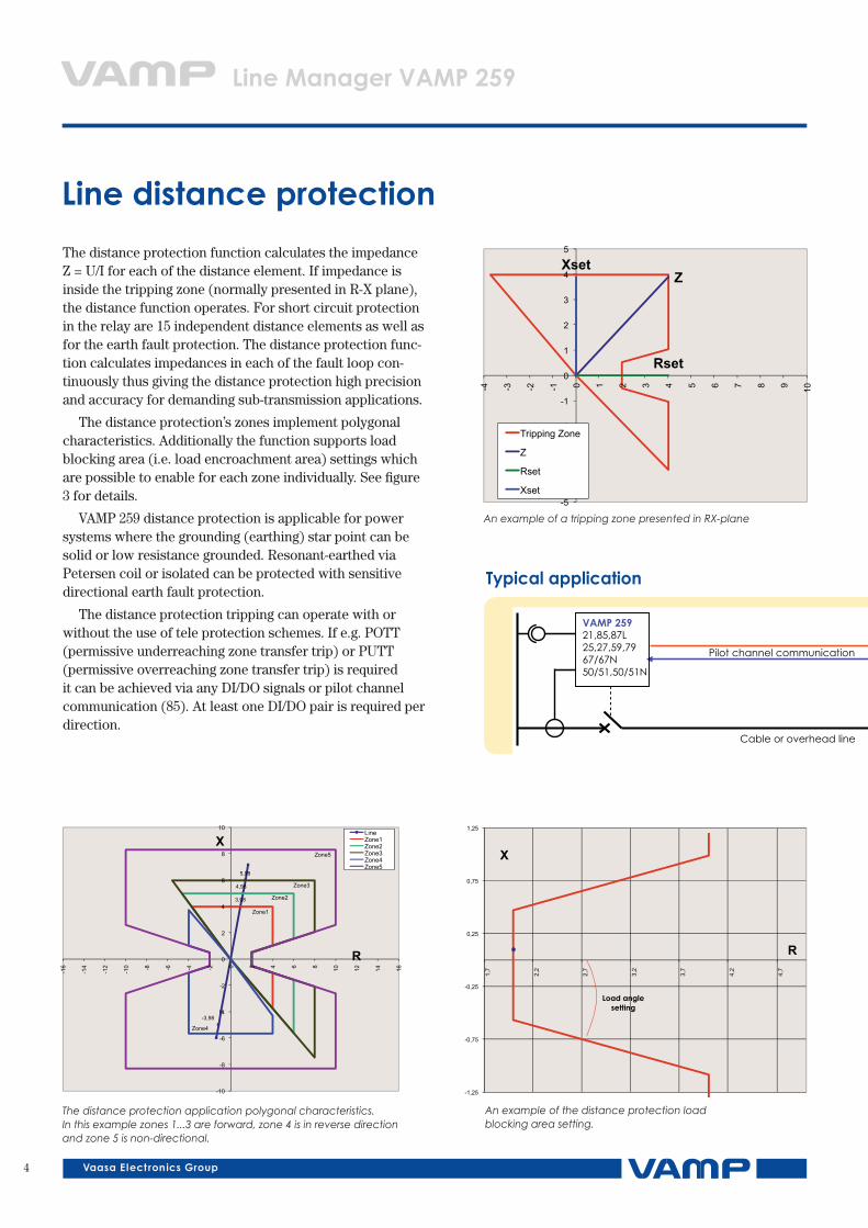
The distance protection function calculates the impedance Z = U/I for each of the distance element. If impedance is inside the tripping zone (normally presented in R-X plane), the distance function operates. For short circuit protection in the relay are 15 independent distance elements as well as for the earth fault protection. The distance protection func-tion calculates impedances in each of the fault loop con-tinuously thus giving the distance protection high precision and accuracy for demanding sub-transmission applications.
The distance protection’s zones implement polygonal characteristics. Additionally the function supports load blocking area (i.e. load encroachment area) settings which are possible to enable for each zone individually. See figure 3 for details.
VAMP 259 distance protection is applicable for power systems where the grounding (earthing) star point can be solid or low resistance grounded. Resonant-earthed via Petersen coil or isolated can be protected with sensitive directional earth fault protection.
The distance protection tripping can operate with or without the use of tele protection schemes. If e.g. POTT (permissive underreaching zone transfer trip) or PUTT (permissive overreaching zone transfer trip) is required it can be achieved via any DI/DO signals or pilot channel communication (85). At least one DI/DO pair is required per direction.
Line distance protection
Z
Rset
Xset
-5
-4
-3
-2
-1
0
1
2
3
4
5
-4 -3 -2 -1 0 1 2 3 4 5 6 7 8 9 10
Tripping Zone
Z
Rset
Xset
An example of a tripping zone presented in RX-plane
-3,98
3,98
4,98
5,98
Zone1
Zone2
Zone3
Zone4
Zone5
R
X
-10
-8
-6
-4
-2
0
2
4
6
8
10
-16
-14
-12
-10 -8 -6 -4 -2 0 2 4 6 8 10 12 14 16
LineZone1Zone2Zone3Zone4Zone5
The distance protection application polygonal characteristics. In this example zones 1...3 are forward, zone 4 is in reverse direction and zone 5 is non-directional.
Typicalapplication
VAMP 259 21,85,87L25,27,59,7967/67N50/51,50/51N
VAMP 259 21,85,8725,27,59,7967/67N50/51,50/51N
Pilot channel communication
Cable or overhead line
An example of the distance protection load blocking area setting.
R
X
Load angle setting
-1,25
-0,75
-0,25
0,25
0,75
1,25
1,7
2,2
2,7
3,2
3,7
4,2
4,7
5
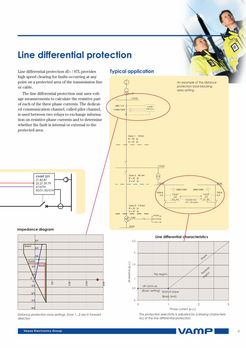
Line differential protection dI> / 87L provides high speed clearing for faults occurring at any point on a protected area of the transmission line or cable.
The line differential protection unit uses volt-age measurements to calculate the resistive part of each of the three phase currents. The dedicat-ed communication channel, called pilot channel, is used between two relays to exchange informa-tion on resistive phase currents and to determine whether the fault is internal or external to the protected area.
Line differential protection
Typicalapplication
VAMP 259 21,85,87L25,27,59,7967/67N50/51,50/51N
VAMP 259 21,85,8725,27,59,7967/67N50/51,50/51N
Pilot channel communication
Cable or overhead line
The protection selectivity is adjusted by a biasing characteris-tics of the line differential protection.
Zone1
Zone2
Zone3
-40
-30
-20
-10
0
10
20
30
40
50
0
50
100
150
200
Zone1
Zone2
Zone3
-40
-30
-20
-10
0
10
20
30
40
50
0
50
100
150
200
Impedancediagram
Distance protection zone settings. Zone 1...3 are in forward direction
0
0,5
1
1,5
2
2,5
dI r
esis
tive
[p
.u.]
Phase current [p.u.]
Trip region
dI> pick-up
(Basic setting) Start of slope
(Basic limit)
0 1 2 3
Slope
Restr
ain
region
Line differential characteristics
An example of the distance protection load blocking area setting.
6
ArcProtectionSeries
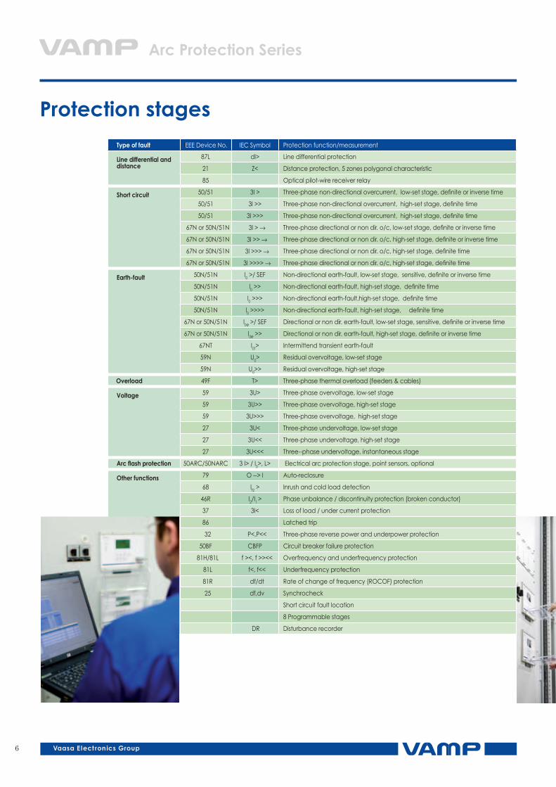
Typeoffault IEEE Device No. IEC Symbol Protection function/measurement
Line differential and distance
87L dI> Line differential protection
21 Z< Distance protection, 5 zones polygonal characteristic
85 Optical pilot-wire receiver relay
Shortcircuit 50/51 3I > Three-phase non-directional overcurrent, low-set stage, definite or inverse time
50/51 3l >> Three-phase non-directional overcurrent, high-set stage, definite time
50/51 3l >>> Three-phase non-directional overcurrent, high-set stage, definite time
67N or 50N/51N 3l > → Three-phase directional or non dir. o/c, low-set stage, definite or inverse time
67N or 50N/51N 3l >> → Three-phase directional or non dir. o/c, high-set stage, definite or inverse time
67N or 50N/51N 3I >>> → Three-phase directional or non dir. o/c, high-set stage, definite time
67N or 50N/51N 3I >>>> → Three-phase directional or non dir. o/c, high-set stage, definite time
Earth-fault 50N/51N l0 >/ SEF Non-directional earth-fault, low-set stage, sensitive, definite or inverse time
50N/51N l0 >> Non-directional earth-fault, high-set stage, definite time
50N/51N l0 >>> Non-directional earth-fault,high-set stage, definite time
50N/51N l0 >>>> Non-directional earth-fault, high-set stage, definite time
67N or 50N/51N l0ϕ >/ SEF Directional or non dir. earth-fault, low-set stage, sensitive, definite or inverse time
67N or 50N/51N l0ϕ >> Directional or non dir. earth-fault, high-set stage, definite or inverse time
67NT I0T> Intermittend transient earth-fault
59N U0> Residual overvoltage, low-set stage
59N U0>> Residual overvoltage, high-set stage
Overload 49F T> Three-phase thermal overload (feeders & cables)
Voltage 59 3U> Three-phase overvoltage, low-set stage
59 3U>> Three-phase overvoltage, high-set stage
59 3U>>> Three-phase overvoltage, high-set stage
27 3U< Three-phase undervoltage, low-set stage
27 3U<< Three-phase undervoltage, high-set stage
27 3U<<< Three--phase undervoltage, instantaneous stage
Arcflashprotection 50ARC/50NARC 3 I> / I0>, L> Electrical arc protection stage, point sensors, optional
Otherfunctions 79 O --> I Auto-reclosure
68 lf2 > Inrush and cold load detection
46R I2/I1 > Phase unbalance / discontinuity protection (broken conductor)
37 3I< Loss of load / under current protection
86 Latched trip
32 P<,P<< Three-phase reverse power and underpower protection
50BF CBFP Circuit breaker failure protection
81H/81L f ><, f >><< Overfrequency and underfrequency protection
81L f<, f<< Underfrequency protection
81R df/dt Rate of change of frequency (ROCOF) protection
25 df,dv Synchrocheck
Short circuit fault location
8 Programmable stages
DR Disturbance recorder
Protection stages
7
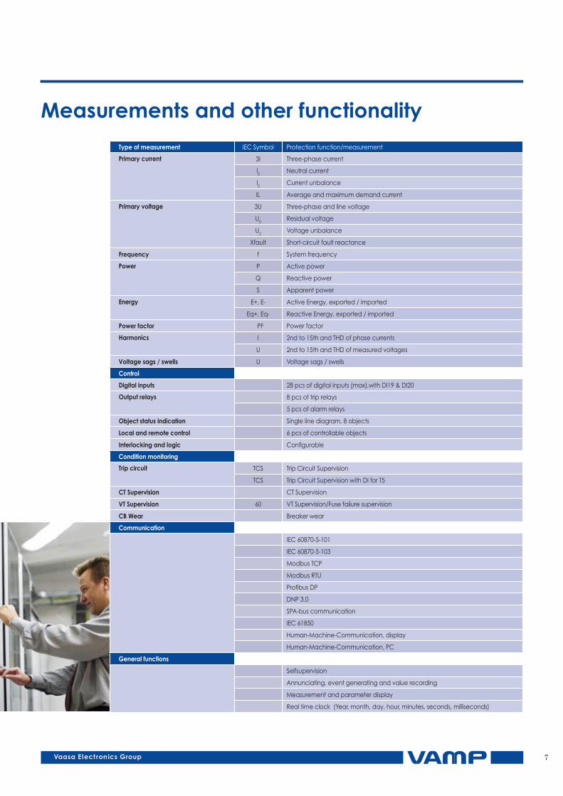
Typeofmeasurement IEC Symbol Protection function/measurement
Primarycurrent 3I Three-phase current
l0 Neutral current
I2 Current unbalance
IL Average and maximum demand current
Primaryvoltage 3U Three-phase and line voltage
U0 Residual voltage
U2 Voltage unbalance
Xfault Short-circuit fault reactance
Frequency f System frequency
Power P Active power
Q Reactive power
S Apparent power
Energy E+, E- Active Energy, exported / imported
Eq+, Eq- Reactive Energy, exported / imported
Power factor PF Power factor
Harmonics I 2nd to 15th and THD of phase currents
U 2nd to 15th and THD of measured voltages
Voltagesags/swells U Voltage sags / swells
Control
Digitalinputs 28 pcs of digital inputs (max),with DI19 & DI20
Outputrelays 8 pcs of trip relays
5 pcs of alarm relays
Objectstatusindication Single line diagram, 8 objects
Local and remote control 6 pcs of controllable objects
Interlockingandlogic Configurable
Conditionmonitoring
Tripcircuit TCS Trip Circuit Supervision
TCS Trip Circuit Supervision with DI for T5
CTSupervision CT Supervision
VTSupervision 60 VT Supervision/Fuse failure supervision
CBWear Breaker wear
Communication
IEC 60870-5-101
IEC 60870-5-103
Modbus TCP
Modbus RTU
Profibus DP
DNP 3.0
SPA-bus communication
IEC 61850
Human-Machine-Communication, display
Human-Machine-Communication, PC
Generalfunctions
Selfsupervision
Annunciating, event generating and value recording
Measurement and parameter display
Real time clock (Year, month, day, hour, minutes, seconds, milliseconds)
Measurementsandotherfunctionality
8
Line Manager VAMP 259
U12
ULLY
UL1
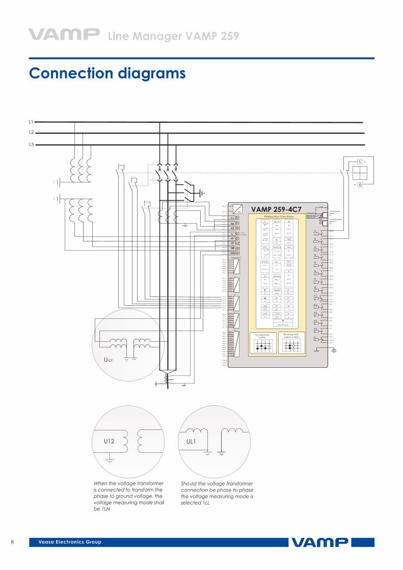
Connectiondiagrams
VAMP 255
L1
L2
L3
0
1
-
-+
+
+
X8:10
X8:11
X8:12
~
X1:1
X1:2
X1:3
X1:4
X1:5
X1:6
X1:7X1:8
X1:9
X1:12
X1:13
X1:14
X1:17
X1:18
X1:10
X1:11
X3:17
X3:18
Protection functions
Option Bloc k
IL1
IL2
IL3
I01
U1
U2
U3
Ulxy
T1 X3:14X3:14
X3:15
T2 X3:12
X3:13
T3 X7:17
X7:18
T4 X7:15
X7:16
IF X2:9
X2:10
X2:11
T5 X8:19
X8:20
A1 X3:9
X3:11
X3:10
X8:17
X8:18
T6
X8:15
X8:16
T7
X8:13
X8:14
T8
A2 X2:7
X2:8
A3 X2:5
X2:6
A4 X2:3
X2:4
A5 X2:1
X2:2
Communicationoption 1
Front
Remote port
Local port
Extension portCommunicationoption 2X10
X9
+48V
X6:2
X6:3
X6:4
X6:5
X6:6
X6:7
X8:1
X8:2
X8:3
X8:4
X8:5
X8:6
X8:7X8:8
X8:9
X8:10
X8:11
X8:12
Comm
X6:1
X3:2
X3:3
X3:4
X3:5
X3:6
X3:7
X3:1DI
DI1
DI2
DI3
DI4
DI5
DI6
X7:2
X7:3
X7:4
X7:5
X7:6
X7:7
X7:1DI
DI8
DI9
DI10
DI11
DI12
DI7
Comm
X7:9
X7:10
X7:11
X7:12
X7:13
X7:14
X7:8DI
DI14
DI15
DI16
DI17
DI18
DI13
DI
Comm
Comm
Comm
Comm
DI18
DI21
DI22
DI23
DI24
DI25
DI26
DI27
DI28
Blocking andoutput matrix
Autoreclosermatrix
CBFP
50BF
I >f2
68
3I<
37
3I>
3I>>
3I>>>
50 / 51
3I>>>
3I>>
3I>
3I>>>>
67
I /I >2 1
46R
ArcI>
50ARC
T >
49
I >>2
47
I >2
46
I >st
48
N>
66
Auto Reclose
79
I >0
67N
I >>0
U<
U<<
U<<<
27
U>
U>>
U>>>
59
I >,0 I >02
I >>,0 I >>02
50N/51N
U >0
U >>0
59N
U >0
U >>0
59N
81H/81L
f ><
f >><<
81L
f <
f <<
50NARC
ArcI >01
ArcI >02
U =f
25
32
P <
P <<
df/dt
81R
Z<
21
I >0T
67NT
Ze<
21N
1 A (C )0.2 A (D)
VAMP 259-4C7
When the voltage transformer is connected to transform the phase to ground voltage, the voltage measuring mode shall be 1LN
Should the voltage transformer connection be phase to phase the voltage measuring mode is selected 1LL
9
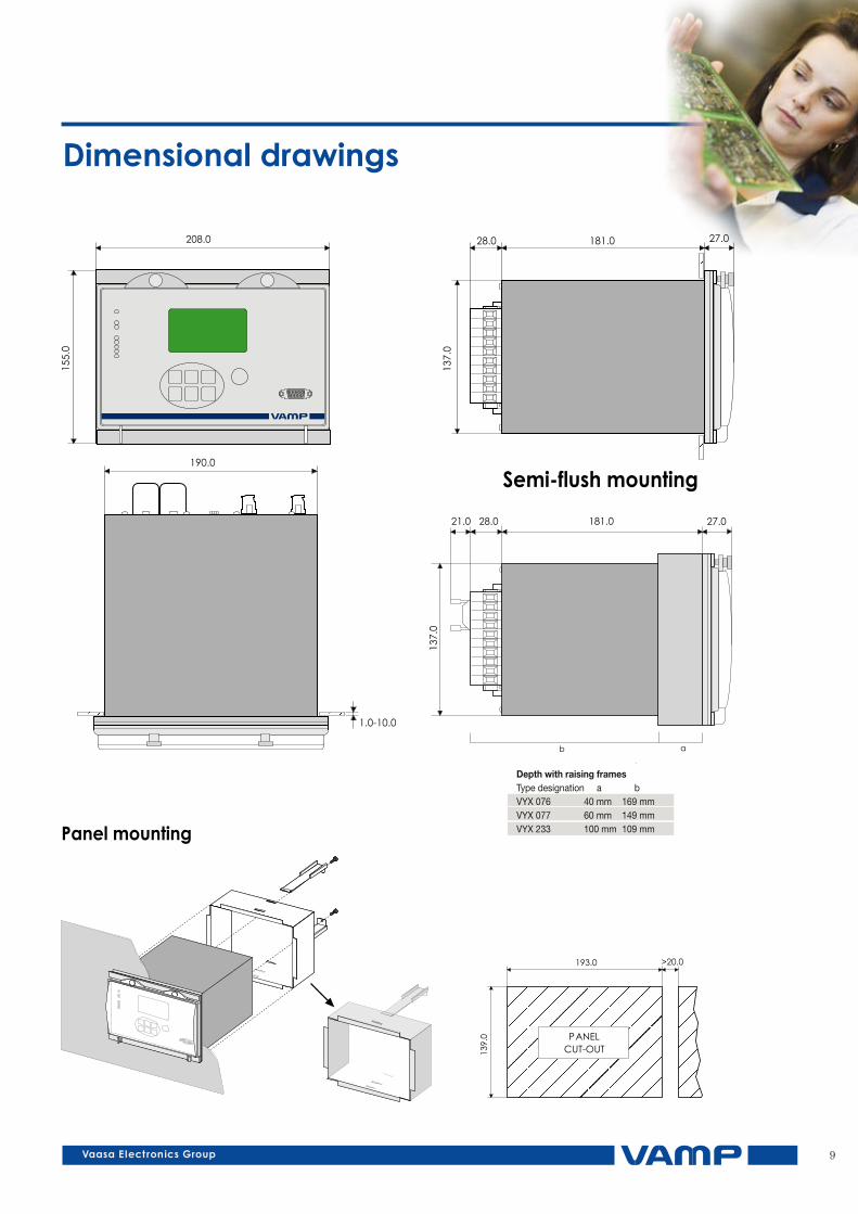
Dimensionaldrawings
10
ArcProtectionSeries
IEC 60870-5-101, IEC 60870-5-103, Modbus RTU, Modbus TCP, Profibus, SPA, DNP 3.0, DNP TCP or IEC 61850
TCP / IP, RS 485 or fibre
Maintenance TerminalSCADA, DCS or SA system
The VAMP relays are easilyinterfaced with anyrenowned andrecognized SCADAsystem
Physical Media:• RS 485• RS 232• Fibre optic• Ethernet
• Relay settings, configuration• Fault and disturbance analysis• Power quality monitoring• Primary equipment condition monitoring• Time synchronizing using GPS
• Control and status of the process• Events• Measurements
• Time synchronizing using GPS• Fault location
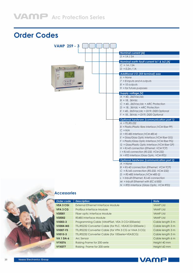
OrderCodesVAMP259-3
Nominal current [A] 3 = 1A / 5A
Nominal earth-fault current Io1 & Io2 [A] C = 1A / 5A D = 0.2A / 1A
Supply voltage [V] A = 40.. 265Vac/dc B = 18.. 36Vdc C = 40.. 265Vac/dc + ARC Protection D = 18.. 36Vdc + ARC Protection E = 40.. 265Vac/dc + DI19, DI20 Optional F = 18.. 36Vdc + DI19, DI20 Optional
Optional hardware (communication port 1) A = TTL/RS-232 B = Plastic/Plastic fibre interface (VCM fiber PP) C = N/A D = RS 485 Interface (VCM 485-4) E = Glass/Glass Optic Interface (VCM fiber GG) F = Plastic/Glass Optic Interface (VCM fiber PG) G = Glass/Plastic Optic Interface (VCM fiber GP) H = RJ-45 connection (Ethernet, VCM TCP) I = RJ-45 connection (RS-232, VCM 232) N = RTD interface (Glass Optic, VCM RTD)
Additional I/O (X8 terminal) aaa6 = None 7 = 8 inputs and 4 outputs 8 = 10 outputs 9 = for future purposes
Optional hardware (communication port 2) A = None B = RJ-45 connection (Ethernet, VCM TCP) C = RJ-45 connection (RS-232, VCM 232) D = RS-485 Interface (VCM 485-2) L = Inbuilt Ethernet, RJ-45 connection M = Inbuilt Ethernet with IEC 61850 N = RTD interface (Glass Optic, VCM RTD)
v
Order code Description Note
VEA3CGi External Ethernet Interface Module VAMP Ltd
VPA3CG Profibus Interface Module VAMP Ltd
VSE001 Fiber optic Interface Module VAMP Ltd
VSE002 RS485 Interface Module VAMP Ltd
VX003-3 Programming Cable (VAMPSet, VEA 3 CG+200serie) Cable length 3 m
VX004-M3 TTL/RS232 Converter Cable (for PLC, VEA3CG+200serie ) Cable length 3 m
VX007-F3 TTL/RS232 Converter Cable (for VPA 3 CG or VMA 3 CG) Cable length 3 m
VX015-3 TTL/RS232 Converter Cable (for 100serie+VEA3CG) Cable length 3 m
VA1DA-6 Arc Sensor Cable length 6 m
VYX076 Raising Frame for 200-serie Height 40 mm
VYX077 Raising Frame for 200-serie Height 60 mm
Accessories
11
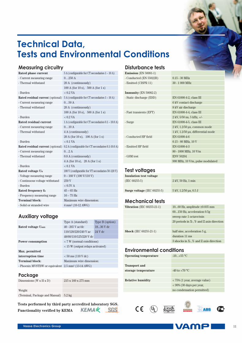
TechnicalData,TestsandEnvironmentalConditionsMeasuring circuitryRated phase current 5 A (configurable for CT secondaries 1 – 10 A)
- Current measuring range 0…250 A
- Thermal withstand 20 A (continuously)
100 A (for 10 s), 500 A (for 1 s)
- Burden < 0.2 VA
Rated residual current (optional) 5 A (configurable for CT secondaries 1 – 10 A)
- Current measuring range 0…50 A
- Thermal withstand 20 A (continuously)
100 A (for 10 s), 500 A (for 1 s)
- Burden < 0.2 VA
Rated residual current 1 A (configurable for CT secondaries 0.1 – 10.0 A)
- Current measuring range 0…10 A
- Thermal withstand 4 A (continuously)
20 A (for 10 s), 100 A (for 1 s)
- Burden < 0.1 VA
Rated residual current (optional) 0.2 A (configurable for CT secondaries 0.1-10.0 A)
- Current measuring range 0…2 A
- Thermal withstand 0.8 A (continuously)
4 A (for 10 s), 20 A (for 1 s)
- Burden < 0.1 VA
Rated voltage Un 100 V (configurable for VT secondaries 50-120 V)
- Voltage measuring range 0 – 160 V (100 V/110 V)
- Continuous voltage withstand 250 V
- Burden < 0.5V A
Rated frequency fn 45 – 65 Hz
- Frequency measuring range 16 – 75 Hz
Terminal block: Maximum wire dimension:
- Solid or stranded wire 4 mm2 (10-12 AWG)
Auxiliary voltageType A (standard) Type B (option)
Rated voltage Uaux 40 - 265 V ac/dc 18...36 V dc
110/120/220/240 V ac 24 V dc
48/60/110/125/220 V dc
Power consumption < 7 W (normal conditions)
< 15 W (output relays activated)
Max. permitted
interruption time < 50 ms (110 V dc)
Terminal block: Maximum wire dimension:
- Phoenix MVSTBW or equivalent 2.5 mm2 (13-14 AWG)
PackageDimensions (W x H x D) 215 x 160 x 275 mm
Weight
(Terminal, Package and Manual) 5.2 kg
Disturbance testsEmission (EN 50081-1)
- Conducted (EN 55022B) 0.15 - 30 MHz
- Emitted (CISPR 11) 30 - 1 000 MHz
Immunity (EN 50082-2)
- Static discharge (ESD) EN 61000-4-2, class III
6 kV contact discharge
8 kV air discharge
- Fast transients (EFT) EN 61000-4-4, class III
2 kV, 5/50 ns, 5 kHz, +/-
- Surge EN 61000-4-5, class III
2 kV, 1.2/50 µs, common mode
1 kV, 1.2/50 µs, differential mode
- Conducted HF field EN 61000-4-6
0.15 - 80 MHz, 10 V
- Emitted HF field EN 61000-4-3
80 - 1000 MHz, 10 V/m
- GSM test ENV 50204
900 MHz, 10 V/m, pulse modulated
Test voltagesInsulation test voltage
(IEC 60255-5) 2 kV, 50 Hz, 1 min
Surge voltage (IEC 60255-5) 5 kV, 1.2/50 µs, 0.5 J
Mechanical testsVibration (IEC 60255-21-1) 10...60 Hz, amplitude ±0.035 mm
60...150 Hz, acceleration 0.5g
sweep rate 1 octave/min
20 periods in X-, Y- and Z axis direction
Shock (IEC 60255-21-1) half sine, acceleration 5 g,
duration 11 ms
3 shocks in X-, Y- and Z axis direction
Environmental conditionsOperating temperature -10...+55 oC
Transport and
storage temperature -40 to +70 oC
Relative humidity < 75% (1 year, average value)
< 90% (30 days per year,
no condensation permitted)
Tests performed by third party accredited laboratory SGS.
Functionality verified by KEMA
Vamp LtdP.O.Box 810FI-65101 VAASAFinland
Visiting address:Vaasa Airport ParkYrittäjänkatu 15Vaasa, Finland
Tel: +358 20 753 3200Fax: +358 20 753 3205Email: [email protected]:// www.vamp.fi
We reserve the rights to product alterations without prior notice. Copyright © Vamp Ltd. All trademarks are the property of their respective holders. V
B259
.EN
001
With its headquarters in Finland, Vamp Ltd specializes in protection relays, arc
flash protection and measuring and monitoring units for power systems.
Vamp’s medium-voltage and sub-transmission protection relays are used in a
number of applications, from overhead line feeders and substations to power
plants and industrial power system. Their unique integrated arc fault protection
functionality enhances the safety of both people and property and has made Vamp
a leading brand in arc protection worldwide. All Vamp products meet the latest
international standards and regulations.
Our success is based on competitive standard products, constant development by
our designers possessing experience from three protection relay generations, our
long-term partnerships, flexibility and 24 hour care of the customers.
Our organization has been audited and found to be in accordance with the
requirements of the ISO 9001:2000 management system.