Embed Size (px)
Citation preview

Relion® 670 series
Line distance protection REL670CustomizedProduct Guide
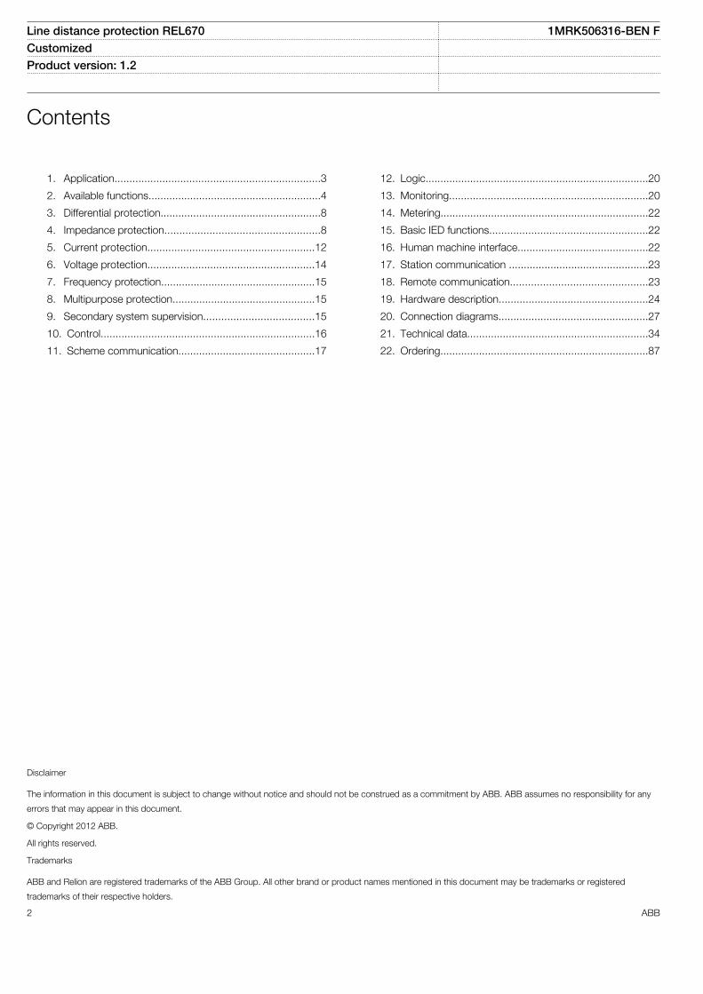
Contents
1. Application.....................................................................3
2. Available functions..........................................................4
3. Differential protection......................................................8
4. Impedance protection....................................................8
5. Current protection........................................................12
6. Voltage protection........................................................14
7. Frequency protection....................................................15
8. Multipurpose protection................................................15
9. Secondary system supervision.....................................15
10. Control........................................................................16
11. Scheme communication..............................................17
12. Logic...........................................................................20
13. Monitoring...................................................................20
14. Metering......................................................................22
15. Basic IED functions.....................................................22
16. Human machine interface............................................22
17. Station communication ...............................................23
18. Remote communication..............................................23
19. Hardware description..................................................24
20. Connection diagrams..................................................27
21. Technical data.............................................................34
22. Ordering......................................................................87
Disclaimer
The information in this document is subject to change without notice and should not be construed as a commitment by ABB. ABB assumes no responsibility for any
errors that may appear in this document.
© Copyright 2012 ABB.
All rights reserved.
Trademarks
ABB and Relion are registered trademarks of the ABB Group. All other brand or product names mentioned in this document may be trademarks or registered
trademarks of their respective holders.
Line distance protection REL670 1MRK506316-BEN FCustomized Product version: 1.2
2 ABB

1. ApplicationREL670 is used for the protection, control and monitoring ofoverhead lines and cables in solidly earthed networks. TheIED can be used up to the high voltage levels. It is suitable forthe protection of heavily loaded lines and multi-terminal lineswhere the requirement for tripping is one-, two-, and/or three-phase. The IED is also suitable as back-up protection ofpower transformers, reactors and so on.
The full scheme distance protection provides protection ofpower lines with high sensitivity and low requirement onremote end communication. The five zones have fullyindependent measuring and setting which gives high flexibilityfor all types of lines.
The modern technical solution offers fast operating time oftypically 1.5 cycles.
The REL670 also includes an alternative for used on notsolidly earthed networks. It includes Phase Preference Logicto select and trip only one line at cross-country faults.
The autoreclose for single-, two-, and/or three-phase recloseincludes priority features for multi-breaker arrangements. It co-operates with the synchrocheck function with high-speed ordelayed reclosing.
A high impedance differential protection can be used toprotect T-feeders or line reactors.
High set instantaneous phase and earth overcurrent, fourstep directional or non-directional delayed phase and earth
overcurrent, sensitive earth fault for not direct earthedsystems, thermal overload and two step under andovervoltage protection are examples of the available functionsallowing the user to fulfill any application requirement.
The distance phase and earth fault protection cancommunicate with remote end in any teleprotectioncommunication scheme. With the included remotecommunication, following the IEEE C37.94 standard, 6 x 32channels for intertrip and binary signals are available perLDCM communication module in the communication betweenthe IEDs.
The IED can also be provided with full bay control andinterlocking functionality including co-operation with thesynchrocheck function to allow integration of the main orback-up control.
Out of Step function is available to separate power systemsections close to electrical centre at occurring out of step.
Disturbance recording and fault locator are available to allowindependent post-fault analysis after primary disturbances.
Serial data communication is via optical connections toensure immunity against disturbances.
The wide application flexibility makes this product anexcellent choice for both new installations and therefurbishment of existing installations.
Line distance protection REL670 1MRK506316-BEN FCustomized Product version: 1.2 Issued: February 2015
Revision: F
ABB 3

2. Available functions
Main protection functions
2 = number of basic instances0-3 = option quantities
IEC 61850 ANSI Function description Line Distance
REL670
Differential protection
HZPDIF 87 1Ph high impedance differential protection 0-3
Impedance protection
ZMQPDIS,ZMQAPDIS
21 Distance protection zone, quadrilateral characteristic 1-5
ZDRDIR 21D Directional impedance quadrilateral 1-2
ZMCPDIS,ZMCAPDIS
21 Distance characteristic for series compensated lines 1-5
ZDSRDIR 21D Directional impedance quadrilateral, including series compensation 1-2
FDPSPDIS 21 Phase selection, quadrilateral characteristic with fixed angle 2
ZMHPDIS 21 Full-scheme distance protection, mho characteristic 1-5
ZMMPDIS,ZMMAPDIS
21 Full-scheme distance protection, quadrilaterial for earth faults 1-5
ZDMRDIR 21D Directional impedance element for mho characteristic 1-2
ZDARDIR Additional distance protection directional function for earth fault 1-2
ZSMGAPC Mho impedance supervision logic 1
FMPSPDIS 21 Faulty phase identification with load enchroachment 2
ZMRPDIS,ZMRAPDIS
21 Distance protection zone, quadrilateral characteristic, separate settings 1-5
FRPSPDIS 21 Phase selection, quadrilateral characteristic with settable angle 2
ZMRPSB 78 Power swing detection 0-1
ZMRPSL Power swing logic 0-1
PSPPPAM 78 Pole slip/out-of-step protection 0-2
ZCVPSOF Automatic switch onto fault logic, voltage and current based 1
PPLPHIZ Phase preference logic 0-1
Line distance protection REL670 1MRK506316-BEN FCustomized Product version: 1.2
4 ABB

Back-up protection functions
IEC 61850 ANSI Function description Line Distance
REL670
Current protection
PHPIOC 50 Instantaneous phase overcurrent protection 0-3
OC4PTOC 51_67 Four step phase overcurrent protection 0-1
EFPIOC 50N Instantaneous residual overcurrent protection 0-3
EF4PTOC 51N_67N
Four step residual overcurrent protection 0-3
NS4PTOC 46I2 Four step directional negative phase sequence overcurrent protection 0-2
SDEPSDE 67N Sensitive directional residual overcurrent and power protection 0-1
LPPTR 26 Thermal overload protection, one time constant 0–2
CCRBRF 50BF Breaker failure protection 0-2
STBPTOC 50STB Stub protection 0-1
CCRPLD 52PD Pole discordance protection 0-2
GUPPDUP 37 Directional underpower protection 0-2
GOPPDOP 32 Directional overpower protection 0-2
BRCPTOC 46 Broken conductor check 1
Voltage protection
UV2PTUV 27 Two step undervoltage protection 0-2
OV2PTOV 59 Two step overvoltage protection 0-2
ROV2PTOV 59N Two step residual overvoltage protection 0-2
OEXPVPH 24 Overexcitation protection 0-1
VDCPTOV 60 Voltage differential protection 0-2
LOVPTUV 27 Loss of voltage check 1
Frequency protection
SAPTUF 81 Underfrequency protection 0-2
SAPTOF 81 Overfrequency protection 0-2
SAPFRC 81 Rate-of-change frequency protection 0-2
Multipurpose protection
CVGAPC General current and voltage protection 0-4
Line distance protection REL670 1MRK506316-BEN FCustomized Product version: 1.2
ABB 5

Control and monitoring functions
IEC 61850 ANSI Function description Line Distance
REL670
Control
SESRSYN 25 Synchrocheck, energizing check and synchronizing 0-2
SMBRREC 79 Autorecloser 0-4
APC8 3 Apparatus control for single bay, max 8 apparatuses (1CB) incl. interlocking 0-1
APC15 3 Apparatus control for single bay, max 15 apparatuses (2CBs) incl. interlocking 0-1
QCBAY Apparatus control 1
LOCREM Handling of LRswitch positions 1
LOCREMCTRL
LHMI control of PSTO 1
SLGGIO Logic rotating switch for function selection and LHMI presentation 15
VSGGIO Selector mini switch 20
DPGGIO IEC61850 generic communication I/O functions 16
SPC8GGIO Single pole generic control 8 signals 5
AutomationBits AutomationBits, command function for DNP3.0 3
SingleCommand16Signals
Single command, 16 signals 4
Secondary system supervision
CCSRDIF 87 Current circuit supervision 0-2
SDDRFUF Fuse failure supervision 0-3
Logic
SMPPTRC 94 Tripping logic 6
TMAGGIO Trip matrix logic 12
Configuration logic blocks 40-420
FixedSignals Fixed signal function block 1
B16I Boolean 16 to Integer conversion 16
B16IFCVI Boolean 16 to Integer conversion with Logic Node representation 16
IB16 Integer to Boolean 16 conversion 16
IB16FCVB Integer to Boolean 16 conversion with Logic Node representation 16
Monitoring
CVMMXN Measurements 6
EVENT Event function 20
DRPRDRE Disturbance report 1
SPGGIO IEC61850 generic communication I/O functions 64
SP16GGIO IEC61850 generic communication I/O functions 16 inputs 16
MVGGIO IEC61850 generic communication I/O functions 24
Line distance protection REL670 1MRK506316-BEN FCustomized Product version: 1.2
6 ABB
IEC 61850 ANSI Function description Line Distance
REL670
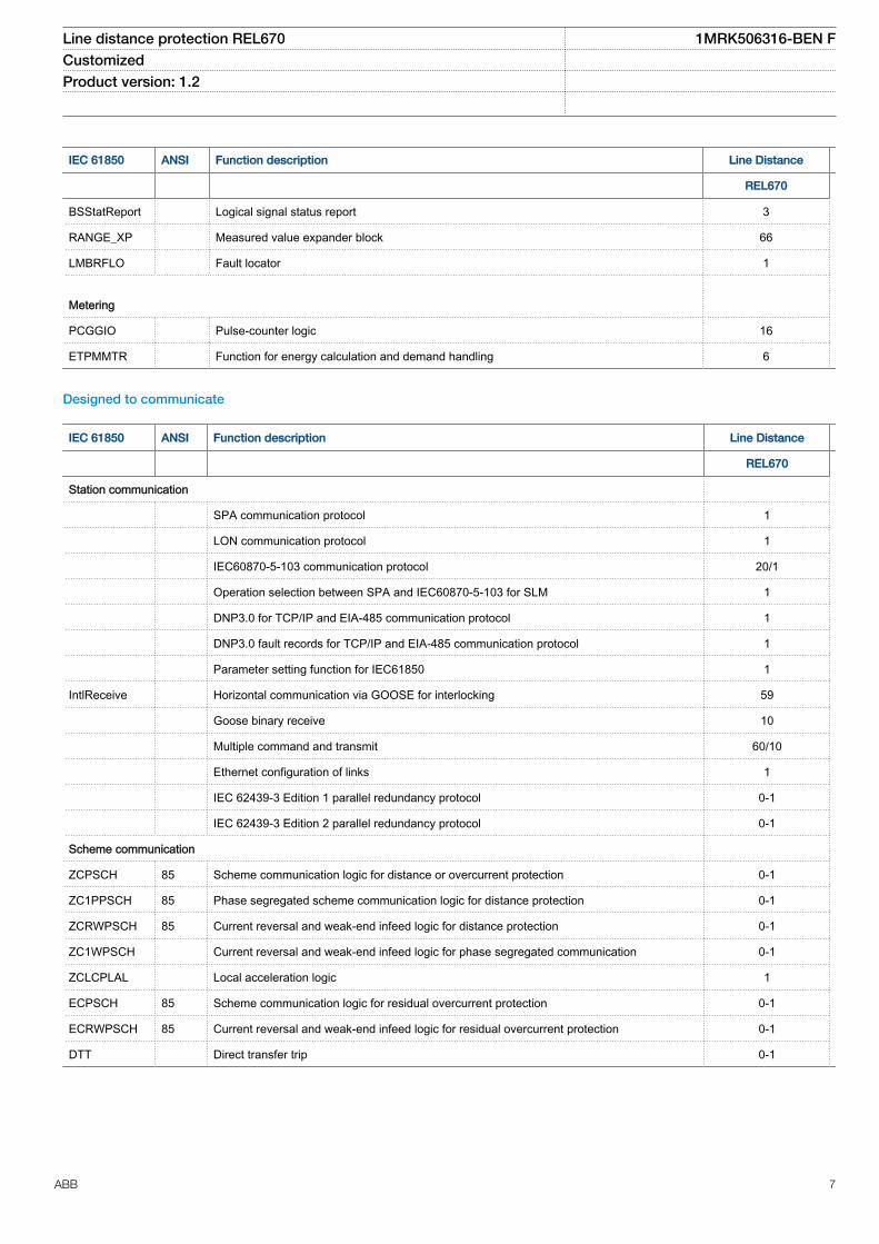
BSStatReport Logical signal status report 3
RANGE_XP Measured value expander block 66
LMBRFLO Fault locator 1
Metering
PCGGIO Pulse-counter logic 16
ETPMMTR Function for energy calculation and demand handling 6
Designed to communicate
IEC 61850 ANSI Function description Line Distance
REL670
Station communication
SPA communication protocol 1
LON communication protocol 1
IEC60870-5-103 communication protocol 20/1
Operation selection between SPA and IEC60870-5-103 for SLM 1
DNP3.0 for TCP/IP and EIA-485 communication protocol 1
DNP3.0 fault records for TCP/IP and EIA-485 communication protocol 1
Parameter setting function for IEC61850 1
IntlReceive Horizontal communication via GOOSE for interlocking 59
Goose binary receive 10
Multiple command and transmit 60/10
Ethernet configuration of links 1
IEC 62439-3 Edition 1 parallel redundancy protocol 0-1
IEC 62439-3 Edition 2 parallel redundancy protocol 0-1
Scheme communication
ZCPSCH 85 Scheme communication logic for distance or overcurrent protection 0-1
ZC1PPSCH 85 Phase segregated scheme communication logic for distance protection 0-1
ZCRWPSCH 85 Current reversal and weak-end infeed logic for distance protection 0-1
ZC1WPSCH Current reversal and weak-end infeed logic for phase segregated communication 0-1
ZCLCPLAL Local acceleration logic 1
ECPSCH 85 Scheme communication logic for residual overcurrent protection 0-1
ECRWPSCH 85 Current reversal and weak-end infeed logic for residual overcurrent protection 0-1
DTT Direct transfer trip 0-1
Line distance protection REL670 1MRK506316-BEN FCustomized Product version: 1.2
ABB 7

Basic IED functions
IEC 61850 Function description
Basic functions included in all products
IntErrorSig Self supervision with internal event list 1
TIME Time and synchronization error 1
TimeSynch Time synchronization 1
ActiveGroup Parameter setting groups 1
Test Test mode functionality 1
ChangeLock Change lock function 1
TerminalID IED identifiers 1
Productinfo Product information 1
MiscBaseCommon Misc Base Common 1
IEDRuntimeComp IED Runtime Comp 1
RatedFreq Rated system frequency 1
SMBI Signal Matrix for binary inputs 40
SMBO Signal Matrix for binary outputs 40
SMMI Signal Matrix for mA inputs 4
SMAI Signal Matrix for analog inputs 24
Sum3Ph Summation block 3 phase 12
LocalHMI Parameter setting function for HMI in PCM600 1
LocalHMI Local HMI signals 1
AuthStatus Authority status 1
AuthorityCheck Authority check 1
AccessFTP FTP access with password 1
SPACommMap SPA communication mapping 1
DOSFRNT Denial of service, frame rate control for front port 1
DOSOEMAB Denial of service, frame rate control for OEM port AB 1
DOSOEMCD Denial of service, frame rate control for OEM port CD 1
3. Differential protection
1Ph High impedance differential protection HZPDIFThe 1Ph High impedance differential protection (HZPDIF)function can be used when the involved CT cores have thesame turns ratio and similar magnetizing characteristics. Itutilizes an external CT current summation by wiring, a seriesresistor, and a voltage dependent resistor which are mountedexternally connected to the IED.
HZPDIF can be used to protect tee-feeders or busbars. Sixsingle phase function blocks are available to allow applicationfor two three-phase zones busbar protection.
4. Impedance protection
Distance measuring zone, quadrilateral characteristicZMQPDIS, ZMQAPDIS (21)The line distance protection is a five zone full schemeprotection with three fault loops for phase-to-phase faults andthree fault loops for phase-to-earth faults for each of theindependent zones. Individual settings for each zone in
Line distance protection REL670 1MRK506316-BEN FCustomized Product version: 1.2
8 ABB
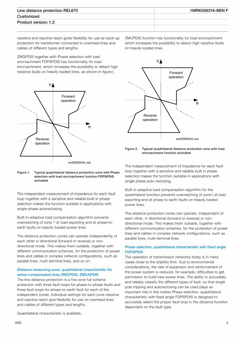
resistive and reactive reach gives flexibility for use as back-upprotection for transformer connected to overhead lines andcables of different types and lengths.
ZMQPDIS together with Phase selection with loadencroachment FDPSPDIS has functionality for loadencroachment, which increases the possibility to detect highresistive faults on heavily loaded lines, as shown in figure1.
en05000034.vsd
R
X
Forwardoperation
Reverseoperation
IEC05000034 V1 EN
Figure 1. Typical quadrilateral distance protection zone with Phaseselection with load encroachment function FDPSPDISactivated
The independent measurement of impedance for each faultloop together with a sensitive and reliable built-in phaseselection makes the function suitable in applications withsingle-phase autoreclosing.
Built-in adaptive load compensation algorithm preventsoverreaching of zone 1 at load exporting end at phase-to-earth faults on heavily loaded power lines.
The distance protection zones can operate independently ofeach other in directional (forward or reverse) or non-directional mode. This makes them suitable, together withdifferent communication schemes, for the protection of powerlines and cables in complex network configurations, such asparallel lines, multi-terminal lines, and so on.
Distance measuring zone, quadrilateral characteristic forseries compensated lines ZMCPDIS, ZMCAPDISThe line distance protection is a five zone full schemeprotection with three fault loops for phase-to-phase faults andthree fault loops for phase-to-earth fault for each of theindependent zones. Individual settings for each zone resistiveand reactive reach give flexibility for use on overhead linesand cables of different types and lengths.
Quadrilateral characteristic is available.
ZMCPDIS function has functionality for load encroachmentwhich increases the possibility to detect high resistive faultson heavily loaded lines.
en05000034.vsd
R
X
Forwardoperation
Reverseoperation
IEC05000034 V1 EN
Figure 2. Typical quadrilateral distance protection zone with loadencroachment function activated
The independent measurement of impedance for each faultloop together with a sensitive and reliable built in phaseselection makes the function suitable in applications withsingle phase auto-reclosing.
Built-in adaptive load compensation algorithm for thequadrilateral function prevents overreaching of zone1 at loadexporting end at phase to earth-faults on heavily loadedpower lines.
The distance protection zones can operate, independent ofeach other, in directional (forward or reverse) or non-directional mode. This makes them suitable, together withdifferent communication schemes, for the protection of powerlines and cables in complex network configurations, such asparallel lines, multi-terminal lines.
Phase selection, quadrilateral characteristic with fixed angleFDPSPDISThe operation of transmission networks today is in manycases close to the stability limit. Due to environmentalconsiderations, the rate of expansion and reinforcement ofthe power system is reduced, for example, difficulties to getpermission to build new power lines. The ability to accuratelyand reliably classify the different types of fault, so that singlepole tripping and autoreclosing can be used plays animportant role in this matter.Phase selection, quadrilateralcharacteristic with fixed angle FDPSPDIS is designed toaccurately select the proper fault loop in the distance functiondependent on the fault type.
Line distance protection REL670 1MRK506316-BEN FCustomized Product version: 1.2
ABB 9

The heavy load transfer that is common in many transmissionnetworks may make fault resistance coverage difficult toachieve. Therefore, FDPSPDIS has a built-in algorithm forload encroachment, which gives the possibility to enlarge theresistive setting of both the phase selection and themeasuring zones without interfering with the load.
The extensive output signals from the phase selection givesalso important information about faulty phase(s), which canbe used for fault analysis.
A current-based phase selection is also included. Themeasuring elements continuously measure three phasecurrents and the residual current and, compare them with theset values.
Full-scheme distance measuring, Mho characteristicZMHPDISThe numerical mho line distance protection is a five zone fullscheme protection for back-up detection of short circuit andearth faults. The full scheme technique provides back-upprotection of power lines with high sensitivity and lowrequirement on remote end communication. The five zoneshave fully independent measuring and settings, which giveshigh flexibility for all types of lines.
The IED can be used up to the highest voltage levels. It issuitable for the protection of heavily loaded lines and multi-terminal lines where the requirement for tripping is one-, two-and/or three-pole.
The independent measurement of impedance for each faultloop together with a sensitive and reliable built in phaseselection makes the function suitable in applications withsingle phase autoreclosing.
Built-in adaptive load compensation algorithm preventsoverreaching at phase-to-earth faults on heavily loaded powerlines, see figure 3.
en07000117.vsd
jX
Operation area Operation area
R
Operation area
No operation area No operation area
IEC07000117 V1 EN
Figure 3. Load encroachment influence on the offset mhocharacteristic
The distance protection zones can operate, independent ofeach other, in directional (forward or reverse) or non-directional mode (offset). This makes them suitable, togetherwith different communication schemes, for the protection ofpower lines and cables in complex network configurations,such as parallel lines, multi-terminal lines and so on.
The possibility to use the phase-to-earth quadrilateralimpedance characteristic together with the mho characteristicincreases the possibility to overcome eventual lack ofsensitivity of the mho element due to the shaping of the curveat remote end faults.
The integrated control and monitoring functions offer effectivesolutions for operating and monitoring all types oftransmission and sub-transmission lines.
Full-scheme distance protection, quadrilateral for earth faultsZMMPDIS, ZMMAPDISThe line distance protection is a five zone protection withthree fault loops for phase-to-earth fault for each of theindependent zones. Individual settings for each zone resistiveand reactive reach give flexibility for use on overhead linesand cables of different types and lengths.
The Full-scheme distance protection, quadrilateral for earthfaults functions ZMMDPIS and ZMMAPDIS have functionalityfor load encroachment, which increases the possibility todetect high resistive faults on heavily loaded lines , see figure1.
Line distance protection REL670 1MRK506316-BEN FCustomized Product version: 1.2
10 ABB

en05000034.vsd
R
X
Forwardoperation
Reverseoperation
IEC05000034 V1 EN
Figure 4. Typical quadrilateral distance protection zone with Phaseselection, quadrilateral characteristic with settable anglefunction FRPSPDIS activated
The independent measurement of impedance for each faultloop together with a sensitive and reliable built in phaseselection makes the function suitable in applications withsingle phase auto-reclosing.
The distance protection zones can operate, independent ofeach other, in directional (forward or reverse) or non-directional mode. This makes them suitable, together withdifferent communication schemes, for the protection of powerlines and cables in complex network configurations, such asparallel lines, multi-terminal lines.
Directional impedance element for Mho characteristicZDMRDIRThe phase-to-earth impedance elements can be optionallysupervised by a phase unselective directional function (phaseunselective, because it is based on symmetrical components).
Mho impedance supervision logic ZSMGAPCThe Mho impedance supervision logic (ZSMGAPC) includesfeatures for fault inception detection and high SIR detection.It also includes the functionality for loss of potential logic aswell as for the pilot channel blocking scheme.
ZSMGAPC can mainly be decomposed in two different parts:
1. A fault inception detection logic2. High SIR detection logic
Faulty phase identification with load encroachment FMPSPDISThe operation of transmission networks today is in manycases close to the stability limit. Due to environmentalconsiderations the rate of expansion and reinforcement of thepower system is reduced, for example difficulties to getpermission to build new power lines. The ability to accurate
and reliable classifying the different types of fault so thatsingle phase tripping and autoreclosing can be used plays animportant roll in this matter.
The phase selection function is design to accurately selectthe proper fault loop(s) in the distance function dependent onthe fault type.
The heavy load transfer that is common in many transmissionnetworks may in some cases interfere with the distanceprotection zone reach and cause unwanted operation.Therefore the function has a built in algorithm for loadencroachment, which gives the possibility to enlarge theresistive setting of the measuring zones without interferingwith the load.
The output signals from the phase selection function produceimportant information about faulty phase(s), which can beused for fault analysis as well.
Distance protection zone, quadrilateral characteristic,separate settings ZMRPDIS, ZMRAPDISThe line distance protection is up to five zone full schemeprotection with three fault loops for phase-to-phase faults andthree fault loops for phase-to-earth fault for each of theindependent zones. Individual settings for each zone inresistive and reactive reach gives flexibility for use as back-upprotection for transformer connected to overhead lines andcables of different types and lengths.
Mho alternative quadrilateral characteristic is available.
ZMRPDIS together with Phase selection, quadrilateralcharacteristic with settable angle FRPSPDIS has functionalityfor load encroachment, which increases the possibility todetect high resistive faults on heavily loaded lines, as shownin figure 1.
Line distance protection REL670 1MRK506316-BEN FCustomized Product version: 1.2
ABB 11

en05000034.vsd
R
X
Forwardoperation
Reverseoperation
IEC05000034 V1 EN
Figure 5. Typical quadrilateral distance protection zone with Phaseselection, quadrilateral characteristic with settable anglefunction FRPSPDIS activated
The independent measurement of impedance for each faultloop together with a sensitive and reliable built-in phaseselection makes the function suitable in applications withsingle pole tripping and autoreclosing.
Built-in adaptive load compensation algorithm preventsoverreaching of zone 1 at load exporting end at phase-to-earth faults on heavily loaded power lines.
The distance protection zones can operate, independent ofeach other, in directional (forward or reverse) or non-directional mode. This makes them suitable, together withdifferent communication schemes, for the protection of powerlines and cables in complex network configurations, such asparallel lines, multi-terminal lines and so on.
Phase selection, quadrilateral characteristic with settableangle FRPSPDISThe operation of transmission networks today is in manycases close to the stability limit. Due to environmentalconsiderations, the rate of expansion and reinforcement ofthe power system is reduced for example, difficulties to getpermission to build new power lines. The ability to accuratelyand reliably classify the different types of fault, so that singlepole tripping and autoreclosing can be used plays animportant role in this matter. The phase selection function isdesigned to accurately select the proper fault loop in thedistance function dependent on the fault type.
The heavy load transfer that is common in many transmissionnetworks may make fault resistance coverage difficult toachieve. Therefore, the function has a built in algorithm forload encroachment, which gives the possibility to enlarge theresistive setting of both the phase selection and themeasuring zones without interfering with the load.
The extensive output signals from the phase selection givesalso important information about faulty phase(s) which can beused for fault analysis.
A current-based phase selection is also included. Themeasuring elements continuously measure three phasecurrents and the residual current and, compare them with theset values.
Power swing detection ZMRPSBPower swings may occur after disconnection of heavy loadsor trip of big generation plants.
Power swing detection function (ZMRPSB) is used to detectpower swings and initiate block of selected distanceprotection zones. Occurrence of earth-fault currents during apower swing inhibits the ZMRPSB function to allow faultclearance.
Power swing logic ZMRPSLAdditional logic is available to secure tripping for faults duringpower swings and prevent tripping at power swings startedby a fault in the network.
Pole slip protection PSPPPAMSudden events in an electrical power system such as largechanges in load, fault occurrence or fault clearance, cancause power oscillations referred to as power swings. In anon-recoverable situation, the power swings become sosevere that the synchronism is lost, a condition referred to aspole slipping. The main purpose of the pole slip protection(PSPPPAM) is to detect, evaluate, and take the requiredaction for pole slipping occurrences in the power system. Theelectrical system parts swinging to each other can beseparated with the line/s closest to the centre of the powerswing allowing the two systems to be stable as separatedislands.
Automatic switch onto fault logic, voltage and current basedZCVPSOFAutomatic switch onto fault logic (ZCVPSOF) is a function thatgives an instantaneous trip at closing of breaker onto a fault.A dead line detection check is provided to activate thefunction when the line is dead.
Phase preference logic PPLPHIZThe optional phase preference logic main purpose is toprovide a selective tripping for cross-country faults in isolatedor high impedance-earthed networks.
5. Current protection
Instantaneous phase overcurrent protection PHPIOCThe instantaneous three phase overcurrent function has a lowtransient overreach and short tripping time to allow use as ahigh set short-circuit protection function.
Line distance protection REL670 1MRK506316-BEN FCustomized Product version: 1.2
12 ABB

Four step phase overcurrent protection OC4PTOCThe four step phase overcurrent protection functionOC4PTOC has an inverse or definite time delay independentfor step 1 and 4 separately. Step 2 and 3 are always definitetime delayed.
All IEC and ANSI inverse time characteristics are availabletogether with an optional user defined time characteristic.
The directional function is voltage polarized with memory. Thefunction can be set to be directional or non-directionalindependently for each of the steps.
Second harmonic blocking level can be set for the functionand can be used to block each step individually
Instantaneous residual overcurrent protection EFPIOCThe Instantaneous residual overcurrent protection EFPIOChas a low transient overreach and short tripping times toallow the use for instantaneous earth-fault protection, with thereach limited to less than the typical eighty percent of the lineat minimum source impedance. EFPIOC can be configured tomeasure the residual current from the three-phase currentinputs or the current from a separate current input. EFPIOCcan be blocked by activating the input BLOCK.
Four step residual overcurrent protection, zero sequence andnegative sequence direction EF4PTOCThe four step residual overcurrent protection EF4PTOC hasan inverse or definite time delay independent for each stepseparately.
All IEC and ANSI time-delayed characteristics are availabletogether with an optional user defined characteristic.
EF4PTOC can be set directional or non-directionalindependently for each of the steps.
IDir, UPol and IPol can be independently selected to be eitherzero sequence or negative sequence.
Second harmonic blocking can be set individually for eachstep.
EF4PTOC can be used as main protection for phase-to-earthfaults.
EF4PTOC can also be used to provide a system back-up forexample, in the case of the primary protection being out ofservice due to communication or voltage transformer circuitfailure.
Directional operation can be combined together withcorresponding communication logic in permissive or blockingteleprotection scheme. Current reversal and weak-end infeedfunctionality are available as well.
EF4PTOC can be configured to measure the residual currentfrom the three-phase current inputs or the current from aseparate current input.
Four step negative sequence overcurrent protectionNS4PTOCFour step negative sequence overcurrent protection(NS4PTOC) has an inverse or definite time delay independentfor each step separately.
All IEC and ANSI time delayed characteristics are availabletogether with an optional user defined characteristic.
The directional function is voltage polarized or dual polarized.
NS4PTOC can be set directional or non-directionalindependently for each of the steps.
NS4PTOC can be used as main protection for unsymmetricalfault; phase-phase short circuits, phase-phase-earth shortcircuits and single phase earth faults.
NS4PTOC can also be used to provide a system back-up forexample, in the case of the primary protection being out ofservice due to communication or voltage transformer circuitfailure.
Directional operation can be combined together withcorresponding communication logic in permissive or blockingteleprotection scheme. The same logic as for directional zerosequence current can be used. Current reversal and weak-end infeed functionality are available.
Sensitive directional residual overcurrent and powerprotection SDEPSDEIn isolated networks or in networks with high impedanceearthing, the earth fault current is significantly smaller thanthe short circuit currents. In addition to this, the magnitude ofthe fault current is almost independent on the fault location inthe network. The protection can be selected to use either theresidual current or residual power component 3U0·3I0·cos j,for operating quantity with maintained short circuit capacity.There is also available one nondirectional 3I0 step and one3U0 overvoltage tripping step.
No specific sensitive current input is needed.SDEPSDE canbe set as low 0.25% of IBase.
Thermal overload protection, one time constant LPTTRThe increasing utilizing of the power system closer to thethermal limits has generated a need of a thermal overloadprotection also for power lines.
A thermal overload will often not be detected by otherprotection functions and the introduction of the thermaloverload protection can allow the protected circuit to operatecloser to the thermal limits.
Line distance protection REL670 1MRK506316-BEN FCustomized Product version: 1.2
ABB 13

The three-phase current measuring protection has an I2tcharacteristic with settable time constant and a thermalmemory..
An alarm level gives early warning to allow operators to takeaction well before the line is tripped.
Breaker failure protection CCRBRFBreaker failure protection (CCRBRF) ensures fast back-uptripping of surrounding breakers in case the own breaker failsto open. CCRBRF can be current based, contact based, oran adaptive combination of these two conditions.
Current check with extremely short reset time is used ascheck criterion to achieve high security against inadvertentoperation.
Contact check criteria can be used where the fault currentthrough the breaker is small.
CCRBRF can be single- or three-phase initiated to allow usewith single phase tripping applications. For the three-phaseversion of CCRBRF the current criteria can be set to operateonly if two out of four for example, two phases or one phaseplus the residual current start. This gives a higher security tothe back-up trip command.
CCRBRF function can be programmed to give a single- orthree-phase re-trip of the own breaker to avoid unnecessarytripping of surrounding breakers at an incorrect initiation dueto mistakes during testing.
Stub protection STBPTOCWhen a power line is taken out of service for maintenanceand the line disconnector is opened in multi-breakerarrangements the voltage transformers will mostly be outsideon the disconnected part. The primary line distanceprotection will thus not be able to operate and must beblocked.
The stub protection STBPTOC covers the zone between thecurrent transformers and the open disconnector. The three-phase instantaneous overcurrent function is released from anormally open, NO (b) auxiliary contact on the linedisconnector.
Pole discordance protection CCRPLDAn open phase can cause negative and zero sequencecurrents which cause thermal stress on rotating machinesand can cause unwanted operation of zero sequence ornegative sequence current functions.
Normally the own breaker is tripped to correct such asituation. If the situation persists the surrounding breakersshould be tripped to clear the unsymmetrical load situation.
The Polediscordance protection function CCRPLD operatesbased on information from auxiliary contacts of the circuit
breaker for the three phases with additional criteria fromunsymmetrical phase currents when required.
Directional over/underpower protection GOPPDOP/GUPPDUPThe directional over-/under-power protection GOPPDOP/GUPPDUP can be used wherever a high/low active, reactiveor apparent power protection or alarming is required. Thefunctions can alternatively be used to check the direction ofactive or reactive power flow in the power system. There area number of applications where such functionality is needed.Some of them are:
• detection of reversed active power flow• detection of high reactive power flow
Each function has two steps with definite time delay. Resettimes for both steps can be set as well.
Broken conductor check BRCPTOCThe main purpose of the function Broken conductor check(BRCPTOC) is the detection of broken conductors onprotected power lines and cables (series faults). Detectioncan be used to give alarm only or trip the line breaker.
6. Voltage protection
Two step undervoltage protection UV2PTUVUndervoltages can occur in the power system during faults orabnormal conditions. Two step undervoltage protection(UV2PTUV) function can be used to open circuit breakers toprepare for system restoration at power outages or as long-time delayed back-up to primary protection.
UV2PTUV has two voltage steps, each with inverse or definitetime delay.
Two step overvoltage protection OV2PTOVOvervoltages may occur in the power system during abnormalconditions such as sudden power loss, tap changerregulating failures, open line ends on long lines etc.
Two step overvoltage protection (OV2PTOV) function can beused to detect open line ends, normally then combined with adirectional reactive over-power function to supervise thesystem voltage. When triggered, the function will cause analarm, switch in reactors, or switch out capacitor banks.
OV2PTOV has two voltage steps, each of them with inverseor definite time delayed.
OV2PTOV has an extremely high reset ratio to allow settingsclose to system service voltage.
Two step residual overvoltage protection ROV2PTOVResidual voltages may occur in the power system duringearth faults.
Line distance protection REL670 1MRK506316-BEN FCustomized Product version: 1.2
14 ABB

Two step residual overvoltage protection ROV2PTOV functioncalculates the residual voltage from the three-phase voltageinput transformers or measures it from a single voltage inputtransformer fed from an open delta or neutral point voltagetransformer.
ROV2PTOV has two voltage steps, each with inverse ordefinite time delay.
Reset delay ensures operation for intermittent earth faults.
Overexcitation protection OEXPVPHWhen the laminated core of a power transformer or generatoris subjected to a magnetic flux density beyond its designlimits, stray flux will flow into non-laminated components notdesigned to carry flux and cause eddy currents to flow. Theeddy currents can cause excessive heating and severedamage to insulation and adjacent parts in a relatively shorttime. The function has settable inverse operating curves andindependent alarm stages.
Voltage differential protection VDCPTOVA voltage differential monitoring function is available. Itcompares the voltages from two three phase sets of voltagetransformers and has one sensitive alarm step and one tripstep.
Loss of voltage check LOVPTUVLoss of voltage check (LOVPTUV) is suitable for use innetworks with an automatic system restoration function.LOVPTUV issues a three-pole trip command to the circuitbreaker, if all three phase voltages fall below the set value fora time longer than the set time and the circuit breakerremains closed.
7. Frequency protection
Underfrequency protection SAPTUFUnderfrequency occurs as a result of a lack of generation inthe network.
Underfrequency protection SAPTUF is used for load sheddingsystems, remedial action schemes, gas turbine startup andso on.
SAPTUF is also provided with undervoltage blocking.
The operation is based on positive sequence voltagemeasurement and requires two phase-phase or three phase-neutral voltages to be connected. For information about howto connect analog inputs, refer to Application manual/IEDapplication/Analog inputs/Setting guidelines
Overfrequency protection SAPTOFOverfrequency protection function SAPTOF is applicable in allsituations, where reliable detection of high fundamental powersystem frequency is needed.
Overfrequency occurs because of sudden load drops orshunt faults in the power network. Close to the generatingplant, generator governor problems can also cause overfrequency.
SAPTOF is used mainly for generation shedding and remedialaction schemes. It is also used as a frequency stage initiatingload restoring.
SAPTOF is provided with an undervoltage blocking.
The operation is based on positive sequence voltagemeasurement and requires two phase-phase or three phase-neutral voltages to be connected. For information about howto connect analog inputs, refer to Application manual/IEDapplication/Analog inputs/Setting guidelines
Rate-of-change frequency protection SAPFRCRate-of-change frequency protection function (SAPFRC) givesan early indication of a main disturbance in the system.SAPFRC can be used for generation shedding, load sheddingand remedial action schemes. SAPFRC can discriminatebetween positive or negative change of frequency.
SAPFRC is provided with an undervoltage blocking. Theoperation is based on positive sequence voltagemeasurement and requires two phase-phase or three phase-neutral voltages to be connected. For information about howto connect analog inputs, refer to Application manual/IEDapplication/Analog inputs/Setting guidelines.
8. Multipurpose protection
General current and voltage protection CVGAPCThe General current and voltage protection (CVGAPC) can beutilized as a negative sequence current protection detectingunsymmetrical conditions such as open phase orunsymmetrical faults.
CVGAPC can also be used to improve phase selection forhigh resistive earth faults, outside the distance protectionreach, for the transmission line. Three functions are used,which measures the neutral current and each of the threephase voltages. This will give an independence from loadcurrents and this phase selection will be used in conjunctionwith the detection of the earth fault from the directional earthfault protection function.
9. Secondary system supervision
Current circuit supervision CCSRDIFOpen or short circuited current transformer cores can causeunwanted operation of many protection functions such asdifferential, earth-fault current and negative-sequence currentfunctions.
It must be remembered that a blocking of protectionfunctions at an occurrence of open CT circuit will mean that
Line distance protection REL670 1MRK506316-BEN FCustomized Product version: 1.2
ABB 15

the situation will remain and extremely high voltages willstress the secondary circuit.
Current circuit supervision (CCSRDIF) compares the residualcurrent from a three phase set of current transformer coreswith the neutral point current on a separate input taken fromanother set of cores on the current transformer.
A detection of a difference indicates a fault in the circuit andis used as alarm or to block protection functions expected togive unwanted tripping.
Fuse failure supervision SDDRFUFThe aim of the fuse failure supervision function (SDDRFUF) isto block voltage measuring functions at failures in thesecondary circuits between the voltage transformer and theIED in order to avoid unwanted operations that otherwisemight occur.
The fuse failure supervision function basically has threedifferent algorithms, negative sequence and zero sequencebased algorithms and an additional delta voltage and deltacurrent algorithm.
The negative sequence detection algorithm is recommendedfor IEDs used in isolated or high-impedance earthednetworks. It is based on the negative-sequence measuringquantities, a high value of voltage 3U2 without the presence
of the negative-sequence current 3I2.
The zero sequence detection algorithm is recommended forIEDs used in directly or low impedance earthed networks. It isbased on the zero sequence measuring quantities, a highvalue of voltage 3U0 without the presence of the residual
current 3I0.
For better adaptation to system requirements, an operationmode setting has been introduced which makes it possible toselect the operating conditions for negative sequence andzero sequence based function. The selection of differentoperation modes makes it possible to choose differentinteraction possibilities between the negative sequence andzero sequence based algorithm.
A criterion based on delta current and delta voltagemeasurements can be added to the fuse failure supervisionfunction in order to detect a three phase fuse failure, which inpractice is more associated with voltage transformerswitching during station operations.
10. Control
Synchrocheck, energizing check, and synchronizing SESRSYNThe Synchronizing function allows closing of asynchronousnetworks at the correct moment including the breaker closingtime, which improves the network stability.
Synchrocheck, energizing check, and synchronizing(SESRSYN) function checks that the voltages on both sides ofthe circuit breaker are in synchronism, or with at least oneside dead to ensure that closing can be done safely.
SESRSYN function includes a built-in voltage selectionscheme for double bus and 1½ breaker or ring busbararrangements.
Manual closing as well as automatic reclosing can bechecked by the function and can have different settings.
For systems which are running asynchronous a synchronizingfunction is provided. The main purpose of the synchronizingfunction is to provide controlled closing of circuit breakerswhen two asynchronous systems are going to be connected.It is used for slip frequencies that are larger than those forsynchrocheck and lower than a set maximum level for thesynchronizing function.
Autorecloser SMBRRECThe autorecloser SMBRREC function provides high-speedand/or delayed auto-reclosing for single or multi-breakerapplications.
Up to five three-phase reclosing attempts can be included byparameter setting. The first attempt can be single-, two and/or three phase for single phase or multi-phase faultsrespectively.
Multiple autoreclosing functions are provided for multi-breakerarrangements. A priority circuit allows one circuit breaker toclose first and the second will only close if the fault proved tobe transient.
Each autoreclosing function is configured to co-operate withthe synchrocheck function.
Apparatus control APCThe apparatus control functions are used for control andsupervision of circuit breakers, disconnectors and earthingswitches within a bay. Permission to operate is given afterevaluation of conditions from other functions such asinterlocking, synchrocheck, operator place selection andexternal or internal blockings.
Apparatus control features:• Select-Execute principle to give high reliability• Selection function to prevent simultaneous operation• Selection and supervision of operator place• Command supervision• Block/deblock of operation• Block/deblock of updating of position indications• Substitution of position indications• Overriding of interlocking functions• Overriding of synchrocheck• Operation counter• Suppression of Mid position
Line distance protection REL670 1MRK506316-BEN FCustomized Product version: 1.2
16 ABB

Two types of command models can be used:• Direct with normal security• SBO (Select-Before-Operate) with enhanced security
In normal security, the command is processed and theresulting position is not supervised. However with enhancedsecurity, the command is processed and the resultingposition is supervised.
Normal security means that only the command is evaluatedand the resulting position is not supervised. Enhancedsecurity means that the command is evaluated with anadditional supervision of the status value of the controlobject. The command security with enhanced security isalways terminated by a CommandTermination serviceprimitive.
Control operation can be performed from the local HMI underauthority control if so defined.
InterlockingThe interlocking function blocks the possibility to operateprimary switching devices, for instance when a disconnectoris under load, in order to prevent material damage and/oraccidental human injury.
Each apparatus control function has interlocking modulesincluded for different switchyard arrangements, where eachfunction handles interlocking of one bay. The interlockingfunction is distributed to each IED and is not dependent onany central function. For the station-wide interlocking, theIEDs communicate via the system-wide interbay bus (IEC61850-8-1) or by using hard wired binary inputs/outputs. Theinterlocking conditions depend on the circuit configurationand apparatus position status at any given time.
For easy and safe implementation of the interlocking function,the IED is delivered with standardized and tested softwareinterlocking modules containing logic for the interlockingconditions. The interlocking conditions can be altered, tomeet the customer’s specific requirements, by addingconfigurable logic by means of the graphical configurationtool.
Logic rotating switch for function selection and LHMIpresentation SLGGIOThe logic rotating switch for function selection and LHMIpresentation (SLGGIO) (or the selector switch function block)is used to get a selector switch functionality similar to the oneprovided by a hardware selector switch. Hardware selectorswitches are used extensively by utilities, in order to havedifferent functions operating on pre-set values. Hardwareswitches are however sources for maintenance issues, lowersystem reliability and an extended purchase portfolio. Thelogic selector switches eliminate all these problems.
Selector mini switch VSGGIOThe Selector mini switch VSGGIO function block is amultipurpose function used for a variety of applications, as ageneral purpose switch.
VSGGIO can be controlled from the menu or from a symbolon the single line diagram (SLD) on the local HMI.
IEC 61850 generic communication I/O functions DPGGIOThe IEC 61850 generic communication I/O functions(DPGGIO) function block is used to send double indications toother systems or equipment in the substation. It is especiallyused in the interlocking and reservation station-wide logics.
Single point generic control 8 signals SPC8GGIOThe Single point generic control 8 signals (SPC8GGIO)function block is a collection of 8 single point commands,designed to bring in commands from REMOTE (SCADA) tothose parts of the logic configuration that do not needextensive command receiving functionality (for example,SCSWI). In this way, simple commands can be sent directlyto the IED outputs, without confirmation. Confirmation (status)of the result of the commands is supposed to be achieved byother means, such as binary inputs and SPGGIO functionblocks. The commands can be pulsed or steady.
AutomationBits, command function for DNP3.0 AUTOBITSAutomationBits function for DNP3 (AUTOBITS) is used withinPCM600 to get into the configuration of the commandscoming through the DNP3 protocol. The AUTOBITS functionplays the same role as functions GOOSEBINRCV (for IEC61850) and MULTICMDRCV (for LON).
Single command, 16 signalsThe IEDs can receive commands either from a substationautomation system or from the local HMI. The commandfunction block has outputs that can be used, for example, tocontrol high voltage apparatuses or for other user definedfunctionality.
11. Scheme communication
Scheme communication logic for distance or overcurrentprotection ZCPSCHTo achieve instantaneous fault clearance for all line faults,scheme communication logic is provided. All types ofcommunication schemes for example, permissiveunderreaching, permissive overreaching, blocking,unblocking, intertrip are available.
The built-in communication module (LDCM) can be used forscheme communication signaling when included.
Phase segregated communication is also available for correctoperation at simultaneous faults when three distanceprotection communication channels are available between theline ends.
Line distance protection REL670 1MRK506316-BEN FCustomized Product version: 1.2
ABB 17

Phase segregated scheme communication logic for distanceprotection ZC1PPSCHCommunication between line ends is used to achieve faultclearance for all faults on a power line. All possible types ofcommunication schemes for example, permissive underreach,permissive overreach and blocking schemes are available. Tomanage problems with simultaneous faults on parallel powerlines phase segregated communication is needed. This willthen replace the standard Scheme communication logic fordistance or Overcurrent protection (ZCPSCH) on importantlines where three communication channels (in eachsubsystem) are available for the distance protectioncommunication.
The main purpose of the Phase segregated schemecommunication logic for distance protection (ZC1PPSCH)function is to supplement the distance protection functionsuch that:
• fast clearance of faults is also achieved at the line endfor which the faults are on the part of the line notcovered by its underreaching zone.
• correct phase selection can be maintained to supportsingle-pole tripping for faults occurring anywhere on theentire length of a double circuit line.
To accomplish this, three separate communication channels,that is, one per phase, each capable of transmitting a signalin each direction is required.
ZC1PPSCH can be completed with the current reversal andWEI logic for phase segregated communication, when foundnecessary in Blocking and Permissive overreaching schemes.
Current reversal and weak-end infeed logic for distanceprotection ZCRWPSCHThe current reversal function is used to prevent unwantedoperations due to current reversal when using permissiveoverreach protection schemes in application with parallel lineswhen the overreach from the two ends overlap on the parallelline.
The weak-end infeed logic is used in cases where theapparent power behind the protection can be too low toactivate the distance protection function. When activated,received carrier signal together with local undervoltage criteriaand no reverse zone operation gives an instantaneous trip.The received signal is also echoed back during 200 ms toaccelerate the sending end.
Three phase or phase segregated scheme logic is available.
Current reversal and weak-end infeed logic for phasesegregated communication ZC1WPSCHCurrent reversal and weak-end infeed logic for phasesegregated communication (ZC1WPSCH) function is used toprevent unwanted operations due to current reversal whenusing permissive overreach protection schemes in application
with parallel lines when the overreach from the two endsoverlaps on the parallel line.
The weak-end infeed logic is used in cases where theapparent power behind the protection can be too low toactivate the distance protection function. When activated,received carrier signal together with local under voltagecriteria and no reverse zone operation gives an instantaneoustrip. The received signal is also echoed back to accelerate thesending end.
Local acceleration logic ZCLCPLALTo achieve fast clearing of faults on the whole line, when nocommunication channel is available, local acceleration logic(ZCLCPLAL) can be used. This logic enables fast faultclearing during certain conditions, but naturally, it can notfully replace a communication channel.
The logic can be controlled either by the autorecloser (zoneextension) or by the loss-of-load current (loss-of-loadacceleration).
Scheme communication logic for residual overcurrentprotection ECPSCHTo achieve fast fault clearance of earth faults on the part ofthe line not covered by the instantaneous step of the residualovercurrent protection, the directional residual overcurrentprotection can be supported with a logic that usescommunication channels.
In the directional scheme, information of the fault currentdirection must be transmitted to the other line end. Withdirectional comparison, a short operate time of the protectionincluding a channel transmission time, can be achieved. Thisshort operate time enables rapid autoreclosing function afterthe fault clearance.
The communication logic module for directional residualcurrent protection enables blocking as well as permissiveunder/overreaching schemes. The logic can also besupported by additional logic for weak-end infeed and currentreversal, included in Current reversal and weak-end infeedlogic for residual overcurrent protection (ECRWPSCH)function.
Current reversal and weak-end infeed logic for residualovercurrent protection ECRWPSCHThe Current reversal and weak-end infeed logic for residualovercurrent protection ECRWPSCH is a supplement toScheme communication logic for residual overcurrentprotection ECPSCH.
To achieve fast fault clearing for all earth faults on the line, thedirectional earth-fault protection function can be supportedwith logic that uses communication channels.
The 670 series IEDs have for this reason available additions toscheme communication logic.
Line distance protection REL670 1MRK506316-BEN FCustomized Product version: 1.2
18 ABB

If parallel lines are connected to common busbars at bothterminals, overreaching permissive communication schemescan trip unselectively due to fault current reversal. Thisunwanted tripping affects the healthy line when a fault iscleared on the other line. This lack of security can result in atotal loss of interconnection between the two buses. To avoidthis type of disturbance, a fault current reversal logic(transient blocking logic) can be used.
Permissive communication schemes for residual overcurrentprotection can basically operate only when the protection inthe remote IED can detect the fault. The detection requires asufficient minimum residual fault current, out from this IED.The fault current can be too low due to an opened breaker orhigh-positive and/or zero-sequence source impedancebehind this IED. To overcome these conditions, weak-endinfeed (WEI) echo logic is used.
Direct transfer trip DTTLow active power and power factor protection LAPPGAPCLow active power and power factor protection (LAPPGAPC)function measures power flow. It can be used for protectionand monitoring of:
• phase wise low active power• phase wise low power factor• phase wise reactive power and apparent power as
service values
Following features are available:
• Definite time stage for low active power protection• Definite time stage for low power factor protection• Individual enabling of Low active power and Low power
factor functions• Low active power trip with 2 selection modes '1 out of 3'
and '2 out of 3'• Phase wise calculated values of apparent power,
reactive power, active power and power factor areavailable as service values
• Insensitive to small variations in voltage and current
Compensated over and undervoltage protection COUVGAPCCompensated over and undervoltage protection(COUVGAPC) function calculates the remote end voltage ofthe transmission line utilizing local measured voltage, currentand with the help of transmission line parameters, that is, lineresistance, reactance, capacitance and local shunt reactor.For protection of long transmission line for in zone faults,COUVGAPCcan be incorporated with local criteria withindirect transfer trip logic to ensure tripping of the line onlyunder abnormal conditions.
Sudden change in current variation SCCVPTOCSudden change in current variation (SCCVPTOC) function is afast way of finding any abnormality in line currents. Whenthere is a fault in the system, the current changes faster thanthe voltage. SCCVPTOC finds abnormal condition based on
phase-to-phase current variation. The main application is as alocal criterion to increase security when transfer trips areused.
Carrier receive logic LCCRPTRCIn Direct transfer trip (DTT) scheme, the received CR signalgives the trip to the circuit breaker after checking certain localcriteria functions in order to increase the security of theoverall tripping functionality. Carrier receive logic(LCCRPTRC) function gives final trip output of the DTTscheme.
Features:
• Carrier redundancy to ensure security in DTT scheme• Blocking function output on CR Channel Error• Phase wise trip outputs
Negative sequence overvoltage protection LCNSPTOVNegative sequence components are present in all types offault condition. Negative sequence voltage and current gethigh values during unsymmetrical faults.
Zero sequence overvoltage protection LCZSPTOVZero sequence components are present in all abnormalconditions involving earth. They can reach considerably highvalues during earth faults.
Negative sequence overcurrent protection LCNSPTOCNegative sequence components are present in all types offault condition. They can reach considerably high valuesduring abnormal operation.
Zero sequence overcurrent protection LCZSPTOCZero sequence components are present in all abnormalconditions involving earth. They have a considerably highvalue during earth faults.
Three phase overcurrent LCP3PTOCThree phase overcurrent (LCP3PTOC) is designed forovercurrent conditions.
Features:
• Phase wise start and trip signals• Overcurrent protection• Phase wise RMS current is available as service values• Single definite time stage trip function.
Three phase undercurrent LCPCPTUCThree phase undercurrent function (LCP3PTUC) is designedfor detecting loss of load conditions.
Features:
• Phase wise start and trip signals• Phase wise RMS current is available as service values• Single definite time stage trip function
Line distance protection REL670 1MRK506316-BEN FCustomized Product version: 1.2
ABB 19

12. Logic
Tripping logic SMPPTRCA function block for protection tripping is provided for eachcircuit breaker involved in the tripping of the fault. It providesa settable pulse prolongation to ensure a trip pulse ofsufficient length, as well as all functionality necessary forcorrect co-operation with autoreclosing functions.
The trip function block also includes a settable latchfunctionality for evolving faults and breaker lock-out.
Trip matrix logic TMAGGIOTrip matrix logic TMAGGIO function is used to route tripsignals and other logical output signals to different outputcontacts on the IED.
TMAGGIO output signals and the physical outputs allows theuser to adapt the signals to the physical tripping outputsaccording to the specific application needs.
Fixed signal function blockThe Fixed signals function (FXDSIGN) generates a number ofpre-set (fixed) signals that can be used in the configuration ofan IED, either for forcing the unused inputs in other functionblocks to a certain level/value, or for creating certain logic.
13. Monitoring
Measurements CVMMXN, CMMXU, VNMMXU, VMMXU,CMSQI, VMSQIThe measurement functions are used to get on-lineinformation from the IED. These service values make itpossible to display on-line information on the local HMI andon the Substation automation system about:
• measured voltages, currents, frequency, active, reactiveand apparent power and power factor
• primary and secondary phasors• positive, negative and zero sequence currents and
voltages• mA, input currents• pulse counters
Supervision of mA input signalsThe main purpose of the function is to measure and processsignals from different measuring transducers. Many devicesused in process control represent various parameters such asfrequency, temperature and DC battery voltage as low currentvalues, usually in the range 4-20 mA or 0-20 mA.
Alarm limits can be set and used as triggers, e.g. to generatetrip or alarm signals.
The function requires that the IED is equipped with the mAinput module.
Event counter CNTGGIOEvent counter (CNTGGIO) has six counters which are used forstoring the number of times each counter input has beenactivated.
Disturbance report DRPRDREComplete and reliable information about disturbances in theprimary and/or in the secondary system together withcontinuous event-logging is accomplished by the disturbancereport functionality.
Disturbance report DRPRDRE, always included in the IED,acquires sampled data of all selected analog input and binarysignals connected to the function block with a, maximum of40 analog and 96 binary signals.
The Disturbance report functionality is a common name forseveral functions:
• Event list• Indications• Event recorder• Trip value recorder• Disturbance recorder• Fault locator
The Disturbance report function is characterized by greatflexibility regarding configuration, starting conditions,recording times, and large storage capacity.
A disturbance is defined as an activation of an input to theAxRADR or BxRBDR function blocks, which are set to triggerthe disturbance recorder. All signals from start of pre-faulttime to the end of post-fault time will be included in therecording.
Every disturbance report recording is saved in the IED in thestandard Comtrade format. The same applies to all events,which are continuously saved in a ring-buffer. The local HMI isused to get information about the recordings. Thedisturbance report files may be uploaded to PCM600 forfurther analysis using the disturbance handling tool.
Event list DRPRDREContinuous event-logging is useful for monitoring the systemfrom an overview perspective and is a complement to specificdisturbance recorder functions.
The event list logs all binary input signals connected to theDisturbance report function. The list may contain up to 1000time-tagged events stored in a ring-buffer.
Indications DRPRDRETo get fast, condensed and reliable information aboutdisturbances in the primary and/or in the secondary system itis important to know, for example binary signals that havechanged status during a disturbance. This information is usedin the short perspective to get information via the local HMI ina straightforward way.
Line distance protection REL670 1MRK506316-BEN FCustomized Product version: 1.2
20 ABB

There are three LEDs on the local HMI (green, yellow andred), which will display status information about the IED andthe Disturbance report function (triggered).
The Indication list function shows all selected binary inputsignals connected to the Disturbance report function thathave changed status during a disturbance.
Event recorder DRPRDREQuick, complete and reliable information about disturbancesin the primary and/or in the secondary system is vital, forexample, time-tagged events logged during disturbances.This information is used for different purposes in the shortterm (for example corrective actions) and in the long term (forexample functional analysis).
The event recorder logs all selected binary input signalsconnected to the Disturbance report function. Each recordingcan contain up to 150 time-tagged events.
The event recorder information is available for thedisturbances locally in the IED.
The event recording information is an integrated part of thedisturbance record (Comtrade file).
Trip value recorder DRPRDREInformation about the pre-fault and fault values for currentsand voltages are vital for the disturbance evaluation.
The Trip value recorder calculates the values of all selectedanalog input signals connected to the Disturbance reportfunction. The result is magnitude and phase angle before andduring the fault for each analog input signal.
The trip value recorder information is available for thedisturbances locally in the IED.
The trip value recorder information is an integrated part of thedisturbance record (Comtrade file).
Disturbance recorder DRPRDREThe Disturbance recorder function supplies fast, completeand reliable information about disturbances in the powersystem. It facilitates understanding system behavior andrelated primary and secondary equipment during and after adisturbance. Recorded information is used for differentpurposes in the short perspective (for example correctiveactions) and long perspective (for example functional analysis).
The Disturbance recorder acquires sampled data fromselected analog- and binary signals connected to theDisturbance report function (maximum 40 analog and 96binary signals). The binary signals available are the same asfor the event recorder function.
The function is characterized by great flexibility and is notdependent on the operation of protection functions. It canrecord disturbances not detected by protection functions. Up
to ten seconds of data before the trigger instant can be savedin the disturbance file.
The disturbance recorder information for up to 100disturbances are saved in the IED and the local HMI is usedto view the list of recordings.
Event functionWhen using a Substation Automation system with LON orSPA communication, time-tagged events can be sent atchange or cyclically from the IED to the station level. Theseevents are created from any available signal in the IED that isconnected to the Event function (EVENT). The event functionblock is used for LON and SPA communication.
Analog and double indication values are also transferredthrough EVENT function.
IEC61850 generic communication I/O function SPGGIOIEC61850 generic communication I/O functions (SPGGIO) isused to send one single logical signal to other systems orequipment in the substation.
IEC61850 generic communication I/O functions MVGGIOIEC61850 generic communication I/O functions (MVGGIO)function is used to send the instantaneous value of an analogsignal to other systems or equipment in the substation. It canalso be used inside the same IED, to attach a RANGE aspectto an analog value and to permit measurement supervision onthat value.
Measured value expander block RANGE_XPThe current and voltage measurements functions (CVMMXN,CMMXU, VMMXU and VNMMXU), current and voltagesequence measurement functions (CMSQI and VMSQI) andIEC 61850 generic communication I/O functions (MVGGIO)are provided with measurement supervision functionality. Allmeasured values can be supervised with four settable limits:low-low limit, low limit, high limit and high-high limit. Themeasure value expander block (RANGE_XP) has beenintroduced to enable translating the integer output signal fromthe measuring functions to 5 binary signals: below low-lowlimit, below low limit, normal, above high-high limit or abovehigh limit. The output signals can be used as conditions in theconfigurable logic or for alarming purpose.
Fault locator LMBRFLOThe accurate fault locator is an essential component tominimize the outages after a persistent fault and/or to pin-point a weak spot on the line.
The fault locator is an impedance measuring function givingthe distance to the fault in percent, km or miles. The mainadvantage is the high accuracy achieved by compensating forload current and for the mutual zero-sequence effect ondouble circuit lines.
The compensation includes setting of the remote and localsources and calculation of the distribution of fault currents
Line distance protection REL670 1MRK506316-BEN FCustomized Product version: 1.2
ABB 21

from each side. This distribution of fault current, together withrecorded load (pre-fault) currents, is used to exactly calculatethe fault position. The fault can be recalculated with newsource data at the actual fault to further increase theaccuracy.
Especially on heavily loaded long lines (where the fault locatoris most important) where the source voltage angles can be upto 35-40 degrees apart the accuracy can be still maintainedwith the advanced compensation included in fault locator.
14. Metering
Pulse counter logic PCGGIOPulse counter (PCGGIO) function counts externally generatedbinary pulses, for instance pulses coming from an externalenergy meter, for calculation of energy consumption values.The pulses are captured by the binary input module and thenread by the function. A scaled service value is available overthe station bus. The special Binary input module withenhanced pulse counting capabilities must be ordered toachieve this functionality.
Function for energy calculation and demand handlingETPMMTROutputs from the Measurements (CVMMXN) function can beused to calculate energy consumption. Active as well asreactive values are calculated in import and export direction.Values can be read or generated as pulses. Maximumdemand power values are also calculated by the function.
15. Basic IED functions
Time synchronizationThe time synchronization source selector is used to select acommon source of absolute time for the IED when it is a partof a protection system. This makes it possible to compareevent and disturbance data between all IEDs in a stationautomation system.
16. Human machine interface
Human machine interfaceThe local human machine interface is available in a small anda medium sized model. The difference between the twomodels is the size of the LCD. The small size LCD can displayseven lines of text and the medium size LCD can display thesingle line diagram with up to 15 objects on each page. Up to12 single line diagram pages can be defined, depending onthe product capability.
The local HMI is divided into zones with different functionality.
• Status indication LEDs.• Alarm indication LEDs, which consist of 15 LEDs (6 red
and 9 yellow) with user printable label. All LEDs areconfigurable from PCM600.
• Liquid crystal display (LCD).• Keypad with push buttons for control and navigation
purposes, switch for selection between local and remotecontrol and reset.
• Isolated RJ45 communication port.
IEC05000055-LITEN V1 EN
Figure 6. Small, alpha numeric HMI
IEC05000056-LITEN V1 EN
Figure 7. Medium graphic HMI, 15 controllable objects
Line distance protection REL670 1MRK506316-BEN FCustomized Product version: 1.2
22 ABB
17. Station communication
OverviewEach IED is provided with a communication interface,enabling it to connect to one or many substation levelsystems or equipment, either on the Substation Automation(SA) bus or Substation Monitoring (SM) bus.
Following communication protocols are available:
• IEC 61850-8-1 communication protocol• LON communication protocol• SPA or IEC 60870-5-103 communication protocol• DNP3.0 communication protocol
Theoretically, several protocols can be combined in the sameIED.
IEC 61850-8-1 communication protocolThe IED is equipped with single or double optical Ethernetrear ports (order dependent) for IEC 61850-8-1 station buscommunication. The IEC 61850-8-1 communication is alsopossible from the optical Ethernet front port. IEC 61850-8-1protocol allows intelligent electrical devices (IEDs) fromdifferent vendors to exchange information and simplifiessystem engineering. Peer-to-peer communication accordingto GOOSE is part of the standard. Disturbance files uploadingis provided.
Serial communication, LONExisting stations with ABB station bus LON can be extendedwith use of the optical LON interface. This allows full SAfunctionality including peer-to-peer messaging andcooperation between existing ABB IED's and the new IED670.
SPA communication protocolA single glass or plastic port is provided for the ABB SPAprotocol. This allows extensions of simple substationautomation systems but the main use is for SubstationMonitoring Systems SMS.
IEC 60870-5-103 communication protocolA single glass or plastic port is provided for theIEC60870-5-103 standard. This allows design of simplesubstation automation systems including equipment fromdifferent vendors. Disturbance files uploading is provided.
DNP3.0 communication protocolAn electrical RS485 and an optical Ethernet port is availablefor the DNP3.0 communication. DNP3.0 Level 2communication with unsolicited events, time synchronizingand disturbance reporting is provided for communication toRTUs, Gateways or HMI systems.
Multiple command and transmitWhen 670 IED's are used in Substation Automation systemswith LON, SPA or IEC60870-5-103 communication protocolsthe Event and Multiple Command function blocks are used as
the communication interface for vertical communication tostation HMI and gateway and as interface for horizontal peer-to-peer communication (over LON only).
IEC 62439-3 Parallel Redundant ProtocolRedundant station bus communication according to IEC62439-3 Edition 1 and IEC 62439-3 Edition 2 are available asoptions in 670 series IEDs. IEC 62439-3 parallel redundantprotocol is an optional quantity and the selection is made atordering. Redundant station bus communication according toIEC 62439-3 uses both port AB and port CD on the OEMmodule.
Select IEC 62439-3 Edition 1 protocol atthe time of ordering when an existingredundant station bus DuoDriver installationis extended.Select IEC 62439-3 Edition 2 protocol atthe time of ordering for new installationswith redundant station bus.IEC 62439-3 Edition 1 is NOT compatiblewith IEC 62439-3 Edition 2.
18. Remote communication
Analog and binary signal transfer to remote endThree analog and eight binary signals can be exchangedbetween two IEDs. This functionality is mainly used for theline differential protection. However it can be used in otherproducts as well. An IED can communicate with up to 4remote IEDs.
Binary signal transfer to remote end, 192 signalsIf the communication channel is used for transfer of binarysignals only, up to 192 binary signals can be exchangedbetween two IEDs. For example, this functionality can beused to send information such as status of primaryswitchgear apparatus or intertripping signals to the remoteIED. An IED can communicate with up to 4 remote IEDs.
Line data communication module, short, medium and longrange LDCMThe line data communication module (LDCM) is used forcommunication between the IEDs situated at distances <110km or from the IED to optical to electrical converter with G.703 or G.703E1 interface located on a distances <3 kmaway. The LDCM module sends and receives data, to andfrom another LDCM module. The IEEE/ANSI C37.94 standardformat is used.
Line distance protection REL670 1MRK506316-BEN FCustomized Product version: 1.2
ABB 23

Galvanic X.21 line data communication module X.21-LDCMA module with built-in galvanic X.21 converter which e.g. canbe connected to modems for pilot wires is also available.
Galvanic interface G.703 resp G.703E1The external galvanic data communication converter G.703/G.703E1 makes an optical-to-galvanic conversion forconnection to a multiplexer. These units are designed for 64kbit/s resp 2Mbit/s operation. The converter is delivered with19” rack mounting accessories.
19. Hardware description
Hardware modulesPower supply module PSMThe power supply module is used to provide the correctinternal voltages and full isolation between the terminal andthe battery system. An internal fail alarm output is available.
Binary input module BIMThe binary input module has 16 optically isolated inputs andis available in two versions, one standard and one withenhanced pulse counting capabilities on the inputs to beused with the pulse counter function. The binary inputs arefreely programmable and can be used for the input of logicalsignals to any of the functions. They can also be included inthe disturbance recording and event-recording functions. Thisenables extensive monitoring and evaluation of operation ofthe IED and for all associated electrical circuits.
Binary output module BOMThe binary output module has 24 independent output relaysand is used for trip output or any signaling purpose.
Static binary output module SOMThe static binary output module has six fast static outputsand six change over output relays for use in applications withhigh speed requirements.
Binary input/output module IOMThe binary input/output module is used when only a few inputand output channels are needed. The ten standard outputchannels are used for trip output or any signaling purpose.The two high speed signal output channels are used forapplications where short operating time is essential. Eightoptically isolated binary inputs cater for required binary inputinformation.
mA input module MIMThe milli-ampere input module is used to interface transducersignals in the –20 to +20 mA range from for example OLTCposition, temperature or pressure transducers. The modulehas six independent, galvanically separated channels.
Optical ethernet module OEMThe optical fast-ethernet module is used to connect an IED tothe communication buses (like the station bus) that use the
IEC 61850-8-1 protocol (port A, B). The module has one ortwo optical ports with ST connectors.
Serial and LON communication module SLM, supports SPA/IEC 60870-5-103, LON and DNP 3.0The serial and LON communication module (SLM) is used forSPA, IEC 60870-5-103, DNP3 and LON communication. Themodule has two optical communication ports for plastic/plastic, plastic/glass or glass/glass. One port is used for serialcommunication (SPA, IEC 60870-5-103 and DNP3 port ordedicated IEC 60870-5-103 port depending on ordered SLMmodule) and one port is dedicated for LON communication.
Line data communication module LDCMEach module has one optical port, one for each remote endto which the IED communicates.
Alternative cards for Long range (1550 nm single mode),Medium range (1310 nm single mode) and Short range (850nm multi mode) are available.
Galvanic X.21 line data communication module X.21-LDCMThe galvanic X.21 line data communication module is used forconnection to telecommunication equipment, for exampleleased telephone lines. The module supports 64 kbit/s datacommunication between IEDs.
Examples of applications:
• Line differential protection• Binary signal transfer
Galvanic RS485 serial communication moduleThe Galvanic RS485 communication module (RS485) is usedfor DNP3.0 communication. The module has one RS485communication port. The RS485 is a balanced serialcommunication that can be used either in 2-wire or 4-wireconnections. A 2-wire connection uses the same signal for RXand TX and is a multidrop communication with no dedicatedMaster or slave. This variant requires however a control of theoutput. The 4-wire connection has separated signals for RXand TX multidrop communication with a dedicated Masterand the rest are slaves. No special control signal is needed inthis case.
GPS time synchronization module GTMThis module includes a GPS receiver used for timesynchronization. The GPS has one SMA contact forconnection to an antenna. It also includes an optical PPS ST-connector output.
IRIG-B Time synchronizing moduleThe IRIG-B time synchronizing module is used for accuratetime synchronizing of the IED from a station clock.
Electrical (BNC) and optical connection (ST) for 0XX and 12XIRIG-B support.
Line distance protection REL670 1MRK506316-BEN FCustomized Product version: 1.2
24 ABB

Transformer input module TRMThe transformer input module is used to galvanically separateand transform the secondary currents and voltages generatedby the measuring transformers. The module has twelve inputsin different combinations of currents and voltage inputs.
Alternative connectors of Ring lug or Compression type canbe ordered.
High impedance resistor unitThe high impedance resistor unit, with resistors for pick-upvalue setting and a voltage dependent resistor, is available in
a single phase unit and a three phase unit. Both are mountedon a 1/1 19 inch apparatus plate with compression typeterminals.
Layout and dimensionsDimensions
xx05000003.vsd
CB
E
F
A
D
IEC05000003 V1 EN
Figure 8. 1/2 x 19” case with rear cover
xx05000004.vsdIEC05000004 V1 EN
Figure 9. Side-by-side mounting
Line distance protection REL670 1MRK506316-BEN FCustomized Product version: 1.2
ABB 25

Case size A B C D E F
6U, 1/2 x 19” 265.9 223.7 201.1 242.1 252.9 205.7
6U, 3/4 x 19” 265.9 336.0 201.1 242.1 252.9 318.0
6U, 1/1 x 19” 265.9 448.1 201.1 242.1 252.9 430.3
(mm)
Mounting alternatives• 19” rack mounting kit• Flush mounting kit with cut-out dimensions:
– 1/2 case size (h) 254.3 mm (w) 210.1 mm– 3/4 case size (h) 254.3 mm (w) 322.4 mm– 1/1 case size (h) 254.3 mm (w) 434.7 mm
• Wall mounting kit
See ordering for details about available mounting alternatives.
Line distance protection REL670 1MRK506316-BEN FCustomized Product version: 1.2
26 ABB

20. Connection diagrams
Table 1. Designations for 1/2 x 19” casing with 1 TRM slot
1MRK002801-AC-2-670-1.2-PG V1 EN
Module Rear Positions
PSM X11
BIM, BOM, SOM, IOM orMIM
X31 and X32 etc. to X51and X52
SLM X301:A, B, C, D
LDCM, IRIG-B or RS485 X302
LDCM or RS485 X303
OEM X311:A, B, C, D
LDCM, RS485 or GTM X312, 313
TRM X401
Table 2. Designations for 3/4 x 19” casing with 1 TRM slot
1MRK002801-AC-3-670-1.2-PG V1 EN
Module Rear Positions
PSM X11
BIM, BOM, SOM, IOM orMIM
X31 and X32 etc. toX101 and X102
SLM X301:A, B, C, D
LDCM, IRIG-B or RS485 X302
LDCM or RS485 X303
OEM X311:A, B, C, D
LDCM, RS485 or GTM X312, X313
TRM X401
Line distance protection REL670 1MRK506316-BEN FCustomized Product version: 1.2
ABB 27
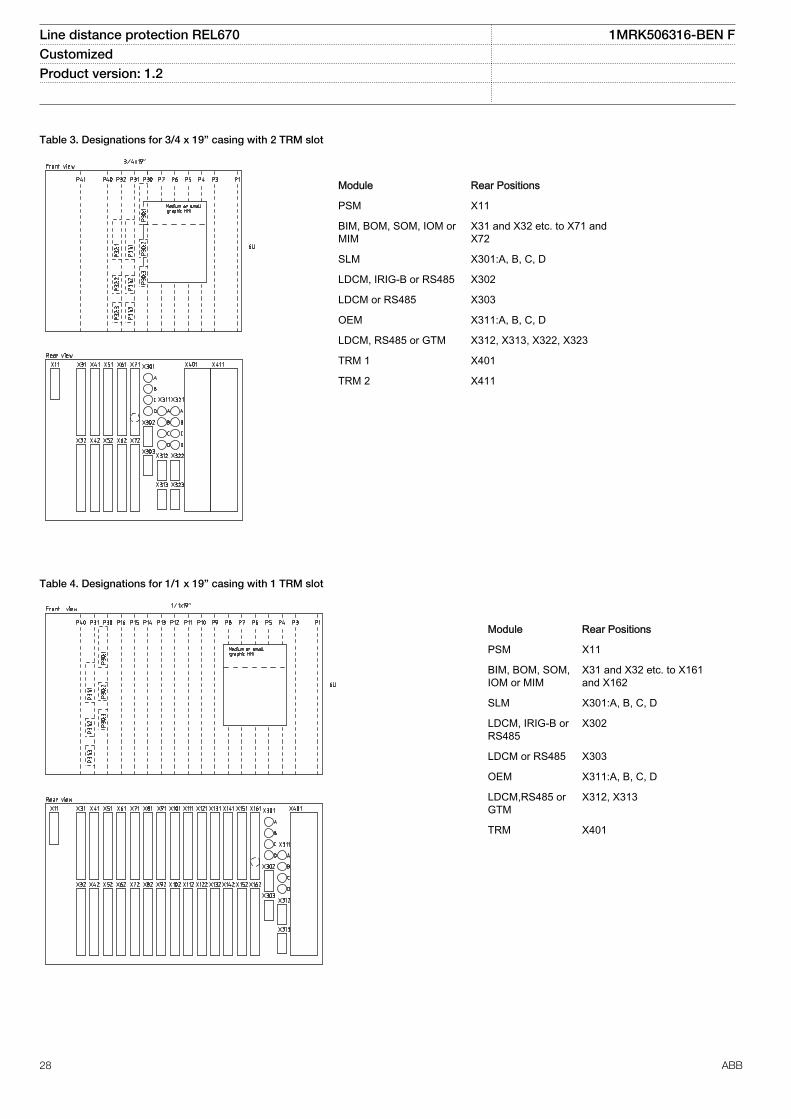
Table 3. Designations for 3/4 x 19” casing with 2 TRM slot
1MRK002801-AC-4-670-1.2-PG V1 EN
Module Rear Positions
PSM X11
BIM, BOM, SOM, IOM orMIM
X31 and X32 etc. to X71 andX72
SLM X301:A, B, C, D
LDCM, IRIG-B or RS485 X302
LDCM or RS485 X303
OEM X311:A, B, C, D
LDCM, RS485 or GTM X312, X313, X322, X323
TRM 1 X401
TRM 2 X411
Table 4. Designations for 1/1 x 19” casing with 1 TRM slot
1MRK002801-AC-5-670-1.2-PG V1 EN
Module Rear Positions
PSM X11
BIM, BOM, SOM,IOM or MIM
X31 and X32 etc. to X161and X162
SLM X301:A, B, C, D
LDCM, IRIG-B orRS485
X302
LDCM or RS485 X303
OEM X311:A, B, C, D
LDCM,RS485 orGTM
X312, X313
TRM X401
Line distance protection REL670 1MRK506316-BEN FCustomized Product version: 1.2
28 ABB

Table 5. Designations for 1/1 x 19” casing with 2 TRM slots
1MRK002801-AC-6-670-1.2-PG V1 EN
Module Rear Positions
PSM X11
BIM, BOM, SOM,IOM or MIM
X31 and X32 etc. to X131and X132
SLM X301:A, B, C, D
LDCM, IRIG-B orRS485
X302
LDCM or RS485 X303
OEM X311:A, B, C, D
LDCM, RS485 orGTM
X312, X313, X322, X323
TRM 1 X401
TRM 2 X411
Line distance protection REL670 1MRK506316-BEN FCustomized Product version: 1.2
ABB 29

1MRK002801-AC-10-670-1.2-PG V1 EN
Figure 10. Transformer input module (TRM)
Indicates high polarity
CT/VT-input designation according to figure 10
Cur
rent
/vol
tage
conf
igur
atio
n(5
0/60
Hz)
AI01 AI02 AI03 AI04 AI05 AI06 AI07 AI08 AI09 AI10 AI11 AI12
9I+3U, 1A 1A 1A 1A 1A 1A 1A 1A 1A 1A 110-220V 110-220V 110-220V9I+3U, 5A 5A 5A 5A 5A 5A 5A 5A 5A 5A 110-220V 110-220V 110-220V5I, 1A+4I, 5A+3U 1A 1A 1A 1A 1A 5A 5A 5A 5A 110-220V 110-220V 110-220V7I+5U, 1A 1A 1A 1A 1A 1A 1A 1A 110-220V 110-220V 110-220V 110-220V 110-220V7I+5U, 5A 5A 5A 5A 5A 5A 5A 5A 110-220V 110-220V 110-220V 110-220V 110-220V6I, 5A+1I, 1A+5U 5A 5A 5A 5A 5A 5A 1A 110-220V 110-220V 110-220V 110-220V 110-220V3I, 5A+4I, 1A+5U 5A 5A 5A 1A 1A 1A 1A 110-220V 110-220V 110-220V 110-220V 110-220V3IM, 1A+4IP, 1A+5U 1AM
*)1AM*)
1AM*)
1A 1A 1A 1A 110-220V 110-220V 110-220V 110-220V 110-220V
3IM, 5A+4IP, 5A+5U 5AM*)
5AM*)
5AM*)
5A 5A 5A 5A 110-220V 110-220V 110-220V 110-220V 110-220V
6I+6U, 1A 1A 1A 1A 1A 1A 1A 110-220V 110-220V 110-220V 110-220V 110-220V 110-220V6I+6U, 5A 5A 5A 5A 5A 5A 5A 110-220V 110-220V 110-220V 110-220V 110-220V 110-220V3I, 5A+3I, 1A+6U 5 A 5 A 5 A 1A 1A 1A 110-220V 110-220V 110-220V 110-220V 110-220V 110-220V6I, 1A 1A 1A 1A 1A 1A 1A - - - - - -6I, 5A 5A 5A 5A 5A 5A 5A - - - - - -*) Metering
Note that internal polarity can be adjusted by setting of analog input CT neutral direction and/or on SMAI pre-processing function blocks.
Line distance protection REL670 1MRK506316-BEN FCustomized Product version: 1.2
30 ABB
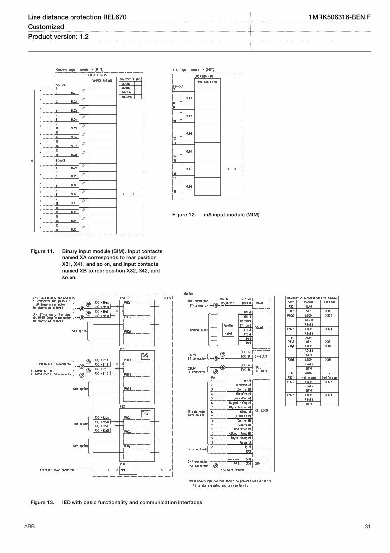
1MRK002801-AC-11-670-1.2-PG V1 EN
Figure 11. Binary input module (BIM). Input contactsnamed XA corresponds to rear positionX31, X41, and so on, and input contactsnamed XB to rear position X32, X42, andso on.
1MRK002801-AC-15-670-1.2-PG V1 EN
Figure 12. mA input module (MIM)
1MRK002801-AC-8-670-1.2-PG V1 EN
Figure 13. IED with basic functionality and communication interfaces
Line distance protection REL670 1MRK506316-BEN FCustomized Product version: 1.2
ABB 31

1MRK002801-AC-7-670-1.2-PG V1 EN
Figure 14. Power supply module (PSM)
1MRK002801-AC-12-670-1.2-PG V1 EN
Figure 15. Binary output module (BOM). Output contacts named XA corresponds to rear position X31, X41, and so on, and outputcontacts named XB to rear position X32, X42, and so on.
Line distance protection REL670 1MRK506316-BEN FCustomized Product version: 1.2
32 ABB

1MRK002801-AC-13-670-1.2-PG V1 EN
Figure 16. Static output module (SOM)
1MRK002801-AC-14-670-1.2-PG V1 EN
Figure 17. Binary in/out module (IOM). Input contacts named XA corresponds to rear position X31, X41, and so on, and output contactsnamed XB to rear position X32, X42, and so on.
Line distance protection REL670 1MRK506316-BEN FCustomized Product version: 1.2
ABB 33

21. Technical data
General
Definitions
Reference value The specified value of an influencing factor to which are referred the characteristics of the equipment
Nominal range The range of values of an influencing quantity (factor) within which, under specified conditions, the equipment meets thespecified requirements
Operative range The range of values of a given energizing quantity for which the equipment, under specified conditions, is able to perform itsintended functions according to the specified requirements
Energizing quantities, rated values and limitsAnalog inputs
Table 6. TRM - Energizing quantities, rated values and limits for protection transformer modules
Quantity Rated value Nominal range
Current Ir = 1 or 5 A (0.2-40) × Ir
Operative range (0-100) x Ir
Permissive overload 4 × Ir cont.100 × Ir for 1 s *)
Burden < 150 mVA at Ir = 5 A< 20 mVA at Ir = 1 A
Ac voltage Ur = 110 V 0.5–288 V
Operative range (0–340) V
Permissive overload 420 V cont.450 V 10 s
Burden < 20 mVA at 110 V
Frequency fr = 50/60 Hz ± 5%
*) max. 350 A for 1 s when COMBITEST test switch is included.
Line distance protection REL670 1MRK506316-BEN FCustomized Product version: 1.2
34 ABB

Table 7. TRM - Energizing quantities, rated values and limits for measuring transformer modules
Quantity Rated value Nominal range
Current Ir = 1 or 5 A (0-1.8) × Irat Ir = 1 A(0-1.6) × Irat Ir = 5 A
Permissive overload 1.1 × Ir cont.1.8 × Ir for 30 min at Ir = 1 A1.6 × Ir for 30 min at Ir = 5 A
Burden < 350 mVA at Ir = 5 A< 200 mVA at Ir = 1 A
Ac voltage Ur = 110 V 0.5–288 V
Operative range (0–340) V
Permissive overload 420 V cont.450 V 10 s
Burden < 20 mVA at 110 V
Frequency fr = 50/60 Hz ± 5%
Table 8. MIM - mA input module
Quantity: Rated value: Nominal range:
Input resistance Rin = 194 Ohm -
Input range ± 5, ± 10, ± 20mA0-5, 0-10, 0-20, 4-20mA
-
Power consumptioneach mA-boardeach mA input
£ 2 W£ 0.1 W
-
Table 9. OEM - Optical ethernet module
Quantity Rated value
Number of channels 1 or 2
Standard IEEE 802.3u 100BASE-FX
Type of fiber 62.5/125 mm multimode fibre
Wave length 1300 nm
Optical connector Type ST
Communication speed Fast Ethernet 100 MB
Auxiliary DC voltage
Table 10. PSM - Power supply module
Quantity Rated value Nominal range
Auxiliary dc voltage, EL (input) EL = (24 - 60) VEL = (90 - 250) V
EL ± 20%EL ± 20%
Power consumption 50 W typically -
Auxiliary DC power in-rush < 5 A during 0.1 s -
Line distance protection REL670 1MRK506316-BEN FCustomized Product version: 1.2
ABB 35

Binary inputs and outputs
Table 11. BIM - Binary input module
Quantity Rated value Nominal range
Binary inputs 16 -
DC voltage, RL 24/30 V48/60 V110/125 V220/250 V
RL ± 20%RL ± 20%RL ± 20%RL ± 20%
Power consumption24/30 V, 50mA48/60 V, 50mA110/125 V, 50mA220/250 V, 50mA220/250 V, 110mA
max. 0.05 W/inputmax. 0.1 W/inputmax. 0.2 W/inputmax. 0.4 W/inputmax. 0.5 W/input
-
Counter input frequency 10 pulses/s max -
Oscillating signal discriminator Blocking settable 1–40 HzRelease settable 1–30 Hz
Debounce filter Settable 1–20ms
Maximum 176 binary input channels maybe activated simultaneously with influencingfactors within nominal range.
Table 12. BIM - Binary input module with enhanced pulse counting capabilities
Quantity Rated value Nominal range
Binary inputs 16 -
DC voltage, RL 24/30 V48/60 V110/125 V220/250 V
RL ± 20%RL ± 20%RL ± 20%RL ± 20%
Power consumption24/30 V48/60 V110/125 V220/250 V
max. 0.05 W/inputmax. 0.1 W/inputmax. 0.2 W/inputmax. 0.4 W/input
-
Counter input frequency 10 pulses/s max -
Balanced counter input frequency 40 pulses/s max -
Oscillating signal discriminator Blocking settable 1–40 HzRelease settable 1–30 Hz
Maximum 176 binary input channels maybe activated simultaneously with influencingfactors within nominal range.
Line distance protection REL670 1MRK506316-BEN FCustomized Product version: 1.2
36 ABB

Table 13. IOM - Binary input/output module
Quantity Rated value Nominal range
Binary inputs 8 -
DC voltage, RL 24/30 V48/60 V110/125 V220/250 V
RL ± 20%RL ± 20%RL ± 20%RL ± 20%
Power consumption24/30 V, 50 mA48/60 V, 50 mA110/125 V, 50 mA220/250 V, 50 mA220/250 V, 110 mA
max. 0.05 W/inputmax. 0.1 W/inputmax. 0.2 W/inputmax. 0.4 W/inputmax. 0.5 W/input
-
Counter input frequency 10 pulses/s max
Oscillating signal discriminator Blocking settable 1-40 HzRelease settable 1-30 Hz
Debounce filter Settable 1-20 ms
Maximum 176 binary input channels maybe activated simultaneously with influencingfactors within nominal range.
Table 14. IOM - Binary input/output module contact data (reference standard: IEC 61810-2)
Function or quantity Trip and signal relays Fast signal relays (parallelreed relay)
Binary outputs 10 2
Max system voltage 250 V AC, DC 250 V DC
Test voltage across open contact, 1 min 1000 V rms 800 V DC
Current carrying capacityPer relay, continuousPer relay, 1 sPer process connector pin, continuous
8 A10 A12 A
8 A10 A12 A
Making capacity at inductive load with L/R>10 ms 0.2 s1.0 s
30 A10 A
0.4 A0.4 A
Making capacity at resistive load 0.2 s1.0 s
30 A10 A
220–250 V/0.4 A110–125 V/0.4 A48–60 V/0.2 A24–30 V/0.1 A
Breaking capacity for AC, cos φ > 0.4 250 V/8.0 A 250 V/8.0 A
Breaking capacity for DC with L/R < 40 ms 48 V/1 A110 V/0.4 A125 V/0.35 A220 V/0.2 A250 V/0.15 A
48 V/1 A110 V/0.4 A125 V/0.35 A220 V/0.2 A250 V/0.15 A
Maximum capacitive load - 10 nF
Line distance protection REL670 1MRK506316-BEN FCustomized Product version: 1.2
ABB 37

Table 15. IOM with MOV and IOM 220/250 V, 110mA - contact data (reference standard: IEC 61810-2)
Function or quantity Trip and Signal relays Fast signal relays (parallel reed relay)
Binary outputs IOM: 10 IOM: 2
Max system voltage 250 V AC, DC 250 V DC
Test voltage across opencontact, 1 min
250 V rms 250 V rms
Current carrying capacityPer relay, continuousPer relay, 1 sPer process connector pin,continuous
8 A10 A12 A
8 A10 A12 A
Making capacity at inductiveloadwith L/R>10 ms0.2 s1.0 s
30 A10 A
0.4 A0.4 A
Making capacity at resistive load 0.2 s1.0 s
30 A10 A
220–250 V/0.4 A110–125 V/0.4 A48–60 V/0.2 A24–30 V/0.1 A
Breaking capacity for AC, cosj>0.4
250 V/8.0 A 250 V/8.0 A
Breaking capacity for DC with L/R < 40 ms
48 V/1 A110 V/0.4 A220 V/0.2 A250 V/0.15 A
48 V/1 A110 V/0.4 A220 V/0.2 A250 V/0.15 A
Maximum capacitive load - 10 nF
Table 16. SOM - Static Output Module (reference standard: IEC 61810-2): Static binary outputs
Function of quantity Static binary output trip
Rated voltage 48 - 60 VDC 110 - 250 VDC
Number of outputs 6 6
Impedance open state ~300 kΩ ~810 kΩ
Test voltage across open contact, 1 min No galvanic separation No galvanic separation
Current carrying capacity:
Continuous 5A 5A
1.0s 10A 10A
Making capacity at capacitive load with themaximum capacitance of 0.2 μF :
0.2s 30A 30A
1.0s 10A 10A
Breaking capacity for DC with L/R ≤ 40ms 48V / 1A 110V / 0.4A
60V / 0.75A 125V / 0.35A
220V / 0.2A
250V / 0.15A
Operating time <1ms <1ms
Line distance protection REL670 1MRK506316-BEN FCustomized Product version: 1.2
38 ABB

Table 17. SOM - Static Output module data (reference standard: IEC 61810-2): Electromechanical relay outputs
Function of quantity Trip and signal relays
Max system voltage 250V AC/DC
Number of outputs 6
Test voltage across open contact, 1 min 1000V rms
Current carrying capacity:
Continuous 8A
1.0s 10A
Making capacity at capacitive load with the maximum capacitance of0.2 μF:
0.2s 30A
1.0s 10A
Breaking capacity for DC with L/R ≤ 40ms 48V / 1A
110V / 0.4A
125V / 0.35A
220V / 0.2A
250V / 0.15A
Table 18. BOM - Binary output module contact data (reference standard: IEC 61810-2)
Function or quantity Trip and Signal relays
Binary outputs 24
Max system voltage 250 V AC, DC
Test voltage across open contact, 1 min 1000 V rms
Current carrying capacityPer relay, continuousPer relay, 1 sPer process connector pin, continuous
8 A10 A12 A
Making capacity at inductive load with L/R>10 ms0.2 s1.0 s
30 A10 A
Breaking capacity for AC, cos j>0.4 250 V/8.0 A
Breaking capacity for DC with L/R < 40 ms 48 V/1 A110 V/0.4 A125 V/0.35 A220 V/0.2 A250 V/0.15 A
Influencing factors
Table 19. Temperature and humidity influence
Parameter Reference value Nominal range Influence
Ambient temperature, operatevalue
+20 °C -10 °C to +55 °C 0.02% /°C
Relative humidityOperative range
10%-90%0%-95%
10%-90% -
Storage temperature -40 °C to +70 °C - -
Line distance protection REL670 1MRK506316-BEN FCustomized Product version: 1.2
ABB 39

Table 20. Auxiliary DC supply voltage influence on functionality during operation
Dependence on Reference value Within nominalrange
Influence
Ripple, in DC auxiliary voltageOperative range
max. 2%Full wave rectified
15% of EL 0.01% /%
Auxiliary voltage dependence, operatevalue
± 20% of EL 0.01% /%
Interrupted auxiliary DC voltage
24-60 V DC ± 20% 90-250 V DC ± 20%
Interruption interval0–50 ms
No restart
0–∞ s Correct behaviour at power down
Restart time <300 s
Table 21. Frequency influence (reference standard: IEC 60255–1)
Dependence on Within nominal range Influence
Frequency dependence, operate value fr ± 2.5 Hz for 50 Hzfr ± 3.0 Hz for 60 Hz
± 1.0% / Hz
Frequency dependence for distance protection operate value fr ± 2.5 Hz for 50 Hzfr ± 3.0 Hz for 60 Hz
±2.0% / Hz
Harmonic frequency dependence (20% content) 2nd, 3rd and 5th harmonic of fr ± 1.0%
Harmonic frequency dependence for distance protection (10% content) 2nd, 3rd and 5th harmonic of fr ± 6.0%
Harmonic frequency dependence for high impedance differentialprotection (10% content)
2nd, 3rd and 5th harmonic of fr ±5.0%
Line distance protection REL670 1MRK506316-BEN FCustomized Product version: 1.2
40 ABB

Type tests according to standards
Table 22. Electromagnetic compatibility
Test Type test values Reference standards
1 MHz burst disturbance 2.5 kV IEC 60255-22-1
100 kHz slow damped oscillatory wave immunity test 2.5 kV IEC 61000-4-18, Class III
Ring wave immunity test, 100 kHz 2-4 kV IEC 61000-4-12, Class IV
Surge withstand capability test 2.5 kV, oscillatory4.0 kV, fast transient
IEEE/ANSI C37.90.1
Electrostatic dischargeDirect applicationIndirect application
15 kV air discharge8 kV contact discharge8 kV contact discharge
IEC 60255-22-2, Class IV IEC 61000-4-2, Class IV
Electrostatic dischargeDirect applicationIndirect application
15 kV air discharge8 kV contact discharge8 kV contact discharge
IEEE/ANSI C37.90.1
Fast transient disturbance 4 kV IEC 60255-22-4, Class A
Surge immunity test 1-2 kV, 1.2/50 mshigh energy
IEC 60255-22-5
Power frequency immunity test 150-300 V, 50 Hz IEC 60255-22-7, Class A
Conducted common mode immunity test 15 Hz-150 kHz IEC 61000-4-16, Class IV
Power frequency magnetic field test 1000 A/m, 3 s100 A/m, cont.
IEC 61000-4-8, Class V
Damped oscillatory magnetic field test 100 A/m IEC 61000-4-10, Class V
Radiated electromagnetic field disturbance 20 V/m, 80-1000 MHz 1.4-2.7 GHz
IEC 60255-22-3
Radiated electromagnetic field disturbance 35 V/m26-1000 MHz
IEEE/ANSI C37.90.2
Conducted electromagnetic field disturbance 10 V, 0.15-80 MHz IEC 60255-22-6
Radiated emission 30-1000 MHz IEC 60255-25
Conducted emission 0.15-30 MHz IEC 60255-25
Table 23. Insulation
Test Type test values Reference standard
Dielectric test 2.0 kV AC, 1 min. IEC 60255-5
Impulse voltage test 5 kV, 1.2/50 ms, 0.5 J
Insulation resistance >100 MW at 500 VDC
Line distance protection REL670 1MRK506316-BEN FCustomized Product version: 1.2
ABB 41

Table 24. Environmental tests
Test Type test value Reference standard
Cold test Test Ad for 16 h at -25°C IEC 60068-2-1
Storage test Test Ad for 16 h at -40°C IEC 60068-2-1
Dry heat test Test Bd for 16 h at +70°C IEC 60068-2-2
Damp heat test, steady state Test Ca for 4 days at +40 °C and humidity 93% IEC 60068-2-78
Damp heat test, cyclic Test Db for 6 cycles at +25 to +55 °C and humidity 93 to 95% (1 cycle =24 hours)
IEC 60068-2-30
Table 25. CE compliance
Test According to
Immunity EN 50263
Emissivity EN 50263
Low voltage directive EN 50178
Table 26. Mechanical tests
Test Type test values Reference standards
Vibration response test Class II IEC 60255-21-1
Vibration endurance test Class I IEC 60255-21-1
Shock response test Class II IEC 60255-21-2
Shock withstand test Class I IEC 60255-21-2
Bump test Class I IEC 60255-21-2
Seismic test Class II IEC 60255-21-3
Line distance protection REL670 1MRK506316-BEN FCustomized Product version: 1.2
42 ABB

Differential protection
Table 27. 1Ph High impedance differential protection HZPDIF
Function Range or value Accuracy
Operate voltage (20-400) VI=U/R
± 1.0% of Ir
Reset ratio >95% -
Maximum continuous power U>Trip2/SeriesResistor ≤200 W -
Operate time 10 ms typically at 0 to 10 x Ud -
Reset time 105 ms typically at 10 to 0 x Ud -
Critical impulse time 2 ms typically at 0 to 10 x Ud -
Line distance protection REL670 1MRK506316-BEN FCustomized Product version: 1.2
ABB 43

Impedance protection
Table 28. Distance measuring zone, Quad ZMQPDIS
Function Range or value Accuracy
Number of zones 5 with selectabledirection
-
Minimum operate residualcurrent, zone 1
(5-1000)% of IBase -
Minimum operate current, phase-to-phase and phase-to-earth
(10-1000)% of IBase -
Positive sequence reactance (0.10-3000.00) Ω/phase
± 2.0% static accuracy± 2.0 degrees static angular accuracyConditions:Voltage range: (0.1-1.1) x Ur
Current range: (0.5-30) x IrAngle: at 0 degrees and 85 degrees
Positive sequence resistance (0.01-1000.00) Ω/phase
Zero sequence reactance (0.10-9000.00) Ω/phase
Zero sequence resistance (0.01-3000.00) Ω/phase
Fault resistance, phase-to-earth (0.10-9000.00) Ω/loop
Fault resistance, phase-to-phase (0.10-3000.00) Ω/loop
Dynamic overreach <5% at 85 degreesmeasured with CVT’sand 0.5<SIR<30
-
Impedance zone timers (0.000-60.000) s ± 0.5% ± 10 ms
Operate time 24 ms typically -
Reset ratio 105% typically -
Reset time 30 ms typically -
Line distance protection REL670 1MRK506316-BEN FCustomized Product version: 1.2
44 ABB

Table 29. Distance measuring zone, quadrilateral characteristic for series compensated lines ZMCPDIS, ZMCAPDIS
Function Range or value Accuracy
Number of zones 5 with selectable direction -
Minimum operate residualcurrent, zone 1
(5-1000)% of IBase -
Minimum operate current, Ph-Phand Ph-E
(10-1000)% of IBase -
Positive sequence reactance (0.10-3000.00) Ω/phase ± 2.0% static accuracy± 2.0 degrees static angular accuracyConditions:Voltage range: (0.1-1.1) x Ur
Current range: (0.5-30) x IrAngle: at 0 degrees and 85 degrees
Positive sequence resistance (0.10-1000.00) Ω/phase
Zero sequence reactance (0.01-9000.00) Ω/phase
Zero sequence resistance (0.01-3000.00) Ω/phase
Fault resistance, Ph-E (0.10-9000.00) Ω/loop
Fault resistance, Ph-Ph (0.10-3000.00) Ω/loop
Dynamic overreach <5% at 85 degrees measuredwith CCVT’s and 0.5<SIR<30
-
Impedance zone timers (0.000-60.000) s ± 0.5% ± 10 ms
Operate time 24 ms typically -
Reset ratio 105% typically -
Reset time 30 ms typically -
Table 30. Phase selection, quadrilateral characteristic with fixed angle FDPSPDIS
Function Range or value Accuracy
Minimum operate current (5-500)% of IBase -
Reactive reach, positivesequence
(0.50–3000.00) Ω/phase ± 2.0% static accuracy± 2.0 degrees static angular accuracyConditions:Voltage range: (0.1-1.1) x Ur
Current range: (0.5-30) x IrAngle: at 0 degrees and 85 degrees
Resistive reach, positivesequence
(0.10–1000.00) Ω/phase
Reactive reach, zero sequence (0.50–9000.00) Ω/phase
Resistive reach, zero sequence (0.50–3000.00) Ω/phase
Fault resistance, phase-to-earthfaults, forward and reverse
(1.00–9000.00) Ω/loop
Fault resistance, phase-to-phasefaults, forward and reverse
(0.50–3000.00) Ω/loop
Load encroachment criteria:Load resistance, forward andreverseSafety load impedance angle
(1.00–3000.00) Ω/phase(5-70) degrees
Reset ratio 105% typically -
Line distance protection REL670 1MRK506316-BEN FCustomized Product version: 1.2
ABB 45

Table 31. Full-scheme distance protection, Mho characteristic ZMHPDIS
Function Range or value Accuracy
Number of zones with selectabledirections
5 with selectable direction -
Minimum operate current (10–30)% of IBase -
Positive sequence impedance,phase-to-earth loop
(0.005–3000.000) W/phase ± 2.0% static accuracyConditions:Voltage range: (0.1-1.1) x Ur
Current range: (0.5-30) x IrAngle: 85 degrees
Positive sequence impedanceangle, phase-to-earth loop
(10–90) degrees
Reverse reach, phase-to-earthloop (Magnitude)
(0.005–3000.000) Ω/phase
Magnitude of earth returncompensation factor KN
(0.00–3.00)
Angle for earth compensationfactor KN
(-180–180) degrees
Dynamic overreach <5% at 85 degrees measuredwith CVT’s and 0.5<SIR<30
-
Timers (0.000-60.000) s ± 0.5% ± 10 ms
Operate time 20 ms typically (with staticoutputs)
-
Reset ratio 105% typically -
Reset time 30 ms typically -
Table 32. Full-scheme distance protection, quadrilateral for earth faults ZMMPDIS
Function Range or value Accuracy
Number of zones 5 with selectable direction -
Minimum operate current (10-30)% of IBase -
Positive sequence reactance (0.50-3000.00) W/phase ± 2.0% static accuracy± 2.0 degrees static angular accuracyConditions:Voltage range: (0.1-1.1) x Ur
Current range: (0.5-30) x IrAngle: at 0 degrees and 85 degrees
Positive sequence resistance (0.10-1000.00) Ω/phase
Zero sequence reactance (0.50-9000.00) Ω/phase
Zero sequence resistance (0.50-3000.00) Ω/phase
Fault resistance, Ph-E (1.00-9000.00) W/loop
Dynamic overreach <5% at 85 degrees measuredwith CCVT’s and 0.5<SIR<30
-
Impedance zone timers (0.000-60.000) s ± 0.5% ± 10 ms
Operate time 24 ms typically -
Reset ratio 105% typically -
Reset time 30 ms typically -
Line distance protection REL670 1MRK506316-BEN FCustomized Product version: 1.2
46 ABB

Table 33. Faulty phase identification with load encroachment FMPSPDIS
Function Range or value Accuracy
Minimum operate current (5-30)% of IBase ± 1.0% of Ir
Load encroachment criteria:Load resistance, forward andreverse
(0.5–3000) W/phase(5–70) degrees
± 2.0% static accuracyConditions:Voltage range: (0.1–1.1) x Ur
Current range: (0.5–30) x IrAngle: at 0 degrees and 85 degrees
Table 34. Distance measuring zone, quadrilateral characteristic, separate settings ZMRPDIS, ZMRAPDIS
Function Range or value Accuracy
Number of zones 5 with selectabledirection
-
Minimum operate residualcurrent, zone 1
(5-1000)% of IBase -
Minimum operate current, phase-to-phase and phase-to-earth
(10-1000)% of IBase -
Positive sequence reactance (0.10-3000.00) Ω/phase
± 2.0% static accuracy± 2.0 degrees static angular accuracyConditions:Voltage range: (0.1-1.1) x Ur
Current range: (0.5-30) x IrAngle: at 0 degrees and 85 degrees
Positive sequence resistance (0.01-1000.00) Ω/phase
Zero sequence reactance (0.10-9000.00) Ω/phase
Zero sequence resistance (0.01-3000.00) Ω/phase
Fault resistance, phase-to-earth (0.10-9000.00) Ω/loop
Fault resistance, phase-to-phase (0.10-3000.00) Ω/loop
Dynamic overreach <5% at 85 degreesmeasured with CVT’sand 0.5<SIR<30
-
Impedance zone timers (0.000-60.000) s ± 0.5% ± 10 ms
Operate time 24 ms typically -
Reset ratio 105% typically -
Reset time 30 ms typically -
Line distance protection REL670 1MRK506316-BEN FCustomized Product version: 1.2
ABB 47
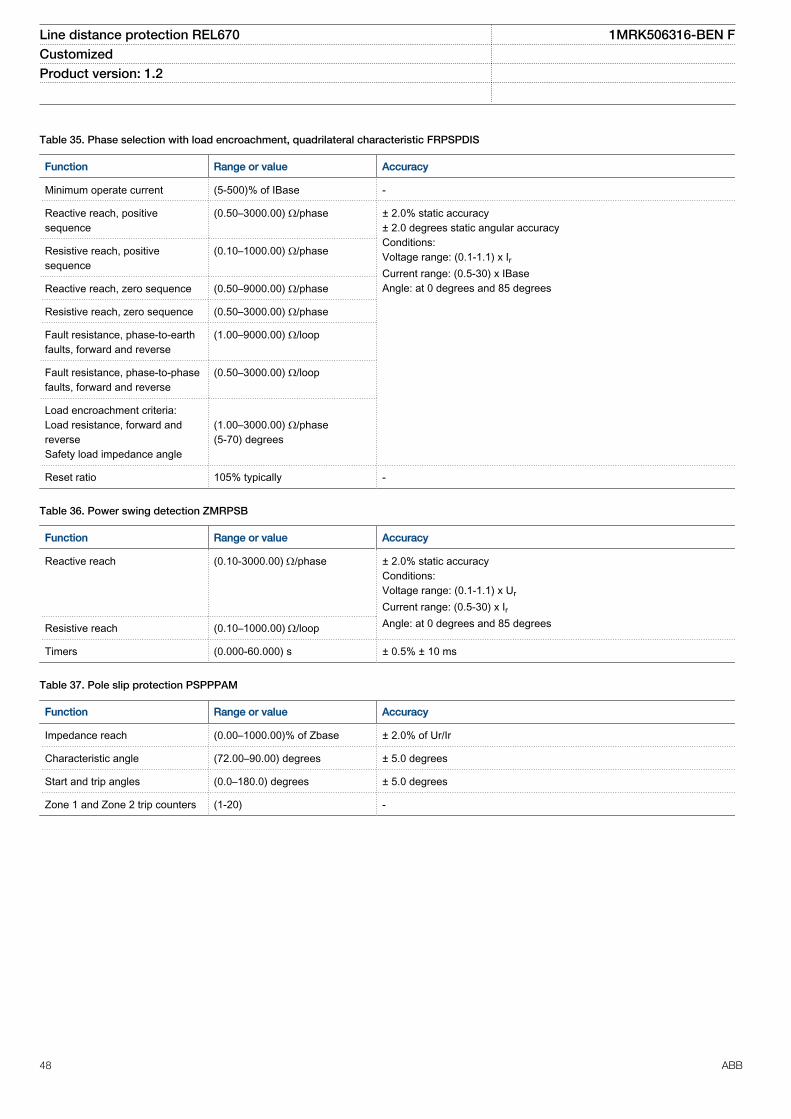
Table 35. Phase selection with load encroachment, quadrilateral characteristic FRPSPDIS
Function Range or value Accuracy
Minimum operate current (5-500)% of IBase -
Reactive reach, positivesequence
(0.50–3000.00) Ω/phase ± 2.0% static accuracy± 2.0 degrees static angular accuracyConditions:Voltage range: (0.1-1.1) x IrCurrent range: (0.5-30) x IBaseAngle: at 0 degrees and 85 degrees
Resistive reach, positivesequence
(0.10–1000.00) Ω/phase
Reactive reach, zero sequence (0.50–9000.00) Ω/phase
Resistive reach, zero sequence (0.50–3000.00) Ω/phase
Fault resistance, phase-to-earthfaults, forward and reverse
(1.00–9000.00) Ω/loop
Fault resistance, phase-to-phasefaults, forward and reverse
(0.50–3000.00) Ω/loop
Load encroachment criteria:Load resistance, forward andreverseSafety load impedance angle
(1.00–3000.00) Ω/phase(5-70) degrees
Reset ratio 105% typically -
Table 36. Power swing detection ZMRPSB
Function Range or value Accuracy
Reactive reach (0.10-3000.00) W/phase
± 2.0% static accuracyConditions:Voltage range: (0.1-1.1) x Ur
Current range: (0.5-30) x IrAngle: at 0 degrees and 85 degreesResistive reach (0.10–1000.00) W/loop
Timers (0.000-60.000) s ± 0.5% ± 10 ms
Table 37. Pole slip protection PSPPPAM
Function Range or value Accuracy
Impedance reach (0.00–1000.00)% of Zbase ± 2.0% of Ur/Ir
Characteristic angle (72.00–90.00) degrees ± 5.0 degrees
Start and trip angles (0.0–180.0) degrees ± 5.0 degrees
Zone 1 and Zone 2 trip counters (1-20) -
Line distance protection REL670 1MRK506316-BEN FCustomized Product version: 1.2
48 ABB

Table 38. Phase preference logic PPLPHIZ
Function Range or value Accuracy
Operate value, phase-to-phaseand phase-to-neutralundervoltage
(10.0 - 100.0)% of UBase ± 0,5% of Ur
Reset ratio, undervoltage < 105% -
Operate value, residual voltage (5.0 - 70.0)% of UBase ± 0,5% of Ur
Reset ratio, residual voltage > 95% -
Operate value, residual current (10 - 200)% of IBase ± 1,0% of Ir for I < Ir± 1,0% of I for I > Ir
Reset ratio, residual current > 95% -
Timers (0.000 - 60.000) s ± 0,5% ± 10 ms
Operating mode No Filter, NoPrefCyclic: 1231c, 1321cAcyclic: 123a, 132a, 213a, 231a,312a, 321a
Table 39. Automatic switch onto fault logic, voltage and current based ZCVPSOF
Parameter Range or value Accuracy
Operate voltage, detection of dead line (1–100)% ofUBase
± 0.5% of Ur
Operate current, detection of dead line (1–100)% of IBase ± 1.0% of Ir
Delay following dead line detection input beforeAutomatic switch into fault logic function isautomatically turned On
(0.000–60.000) s ± 0.5% ± 10 ms
Time period after circuit breaker closure in whichAutomatic switch into fault logic function is active
(0.000–60.000) s ± 0.5% ± 10 ms
Line distance protection REL670 1MRK506316-BEN FCustomized Product version: 1.2
ABB 49

Current protection
Table 40. Instantaneous phase overcurrent protection PHPIOC
Function Range or value Accuracy
Operate current (1-2500)% of lBase ± 1.0% of Ir at I £ Ir± 1.0% of I at I > Ir
Reset ratio > 95% -
Operate time 25 ms typically at 0 to 2 x Iset -
Reset time 25 ms typically at 2 to 0 x Iset -
Critical impulse time 10 ms typically at 0 to 2 x Iset -
Operate time 10 ms typically at 0 to 10 x Iset -
Reset time 35 ms typically at 10 to 0 x Iset -
Critical impulse time 2 ms typically at 0 to 10 x Iset -
Dynamic overreach < 5% at t = 100 ms -
Table 41. Four step phase overcurrent protection OC4PTOC
Function Setting range Accuracy
Operate current (5-2500)% of lBase ± 1.0% of Ir at I ≤ Ir± 1.0% of I at I > Ir
Reset ratio > 95% at (50–2500)% of lBase -
Min. operating current (1-10000)% of lBase ± 1.0% of Ir at I ≤ Ir±1.0% of I at I > Ir
Relay characteristic angle (RCA) (40.0–65.0) degrees ± 2.0 degrees
Relay operating angle (ROA) (40.0–89.0) degrees ± 2.0 degrees
2nd harmonic blocking (5–100)% of fundamental ± 2.0% of Ir
Independent time delay at 0 to 2 xIset
(0.000-60.000) s ± 0.2 % or ± 35 ms whichever isgreater
Minimum operate time (0.000-60.000) s ± 2.0 % or ± 40 ms whichever isgreater
Inverse characteristics, seetable 122, table 123 and table 124
16 curve types See table 122, table 123 and table 124
Operate time, start non-directionalat 0 to 2 x Iset
Min. = 15 ms
Max. = 30 ms
Reset time, start non-directional at2 to 0 x Iset
Min. = 15 ms
Max. = 30 ms
Critical impulse time 10 ms typically at 0 to 2 x Iset -
Impulse margin time 15 ms typically -
Line distance protection REL670 1MRK506316-BEN FCustomized Product version: 1.2
50 ABB

Table 42. Instantaneous residual overcurrent protection EFPIOC
Function Range or value Accuracy
Operate current (1-2500)% of lBase ± 1.0% of Ir at I £ Ir± 1.0% of I at I > Ir
Reset ratio > 95% -
Operate time 25 ms typically at 0 to 2 x Iset -
Reset time 25 ms typically at 2 to 0 x Iset -
Critical impulse time 10 ms typically at 0 to 2 x Iset -
Operate time 10 ms typically at 0 to 10 x Iset -
Reset time 35 ms typically at 10 to 0 x Iset -
Critical impulse time 2 ms typically at 0 to 10 x Iset -
Dynamic overreach < 5% at t = 100 ms -
Table 43. Four step residual overcurrent protection EF4PTOC
Function Range or value Accuracy
Operate current (1-2500)% of lBase ± 1.0% of Ir at I < Ir± 1.0% of I at I > Ir
Reset ratio > 95% -
Operate current for directionalcomparison
(1–100)% of lBase ± 1.0% of Ir
Timers (0.000-60.000) s ± 0.5% ±10 ms
Inverse characteristics, see table122, table 123 and table 124
18 curve types See table 122, table 123 andtable 124
Second harmonic restrainoperation
(5–100)% of fundamental ± 2.0% of Ir
Relay characteristic angle (-180 to 180) degrees ± 2.0 degrees
Minimum polarizing voltage (1–100)% of UBase ± 0.5% of Ur
Minimum polarizing current (1-30)% of IBase ±0.25 % of Ir
Real part of source Z used forcurrent polarization
(0.50-1000.00) W/phase -
Imaginary part of source Z usedfor current polarization
(0.50–3000.00) W/phase -
Operate time, start function 25 ms typically at 0 to 2 x Iset -
Reset time, start function 25 ms typically at 2 to 0 x Iset -
Critical impulse time 10 ms typically at 0 to 2 x Iset -
Impulse margin time 15 ms typically -
Line distance protection REL670 1MRK506316-BEN FCustomized Product version: 1.2
ABB 51

Table 44. Four step negative sequence overcurrent protection NS4PTOC
Function Range or value Accuracy
Operate value, negativesequence current, step 1-4
(1-2500)% of lBase ± 1.0% of Ir at I £ Ir± 1.0% of I at I > Ir
Reset ratio > 95% -
Timers (0.000-60.000) s ± 0.5% ± 10 ms
Inverse characteristics, see table122, table 123 and table 124
18 curve types See table 122, table 123 andtable 124
Minimum operate current for step1 - 4
(1.00 - 10000.00)% of IBase ± 1.0% of Ir at I < Ir± 1.0% of I at I > Ir
Operate value, negative currentfor directional release
(1–100)% of IBase ± 1.0% of Ir
Relay characteristic angle (-180 to 180) degrees ± 2.0 degrees
Minimum polarizing voltage (1–100)% of UBase ± 0.5% of Ur
Minimum polarizing current (2-100)% of IBase ±1.0% of Ir
Real part of negative sequencesource impedance used forcurrent polarization
(0.50-1000.00) W/phase -
Imaginary part of negativesequence source impedanceused for current polarization
(0.50–3000.00) W/phase -
Operate time, start function 25 ms typically at 0.5 to 2 x Iset -
Reset time, start function 25 ms typically at 2 to 0.5 x Iset -
Critical impulse time, startfunction
10 ms typically at 0 to 2 x Iset -
Impulse margin time, startfunction
15 ms typically -
Transient overreach <10% at τ = 100 ms -
Line distance protection REL670 1MRK506316-BEN FCustomized Product version: 1.2
52 ABB

Table 45. Sensitive directional residual overcurrent and power protection SDEPSDE
Function Range or value Accuracy
Operate level for 3I0·cosj
directional residualovercurrent
(0.25-200.00)% of lBase ± 1.0% of Ir at I £ Ir± 1.0% of I at I > Ir At low setting:(0.25-1.00)% of Ir: ±0.05% of Ir(1.00-5.00)% of Ir: ±0.1% of Ir
Operate level for 3I0·3U0 ·cosj directional residualpower
(0.25-200.00)% of SBase ± 1.0% of Sr at S £ Sr
± 1.0% of S at S > Sr
At low setting:(0.25-5.00)% of SBase ± 10% of set value
Operate level for 3I0 and jresidual overcurrent
(0.25-200.00)% of lBase ± 1.0% of Ir at £ Ir± 1.0% of I at I > Ir At low setting:(0.25-1.00)% of Ir: ±0.05% of Ir(1.00-5.00)% of Ir: ±0.1% of Ir
Operate level for non-directional overcurrent
(1.00-400.00)% of lBase ± 1.0% of Ir at I £ Ir± 1.0% of I at I > Ir At low setting <5% of Ir:±0.1% of Ir
Operate level for non-directional residualovervoltage
(1.00-200.00)% of UBase ± 0.5% of Ur at U£Ur
± 0.5% of U at U > Ur
Residual release current forall directional modes
(0.25-200.00)% of lBase ± 1.0% of Ir at I £ Ir± 1.0% of I at I > Ir At low setting:(0.25-1.00)% of Ir: ±0.05% of Ir(1.00-5.00)% of Ir: ±0.1% of Ir
Residual release voltage forall directional modes
(0.01-200.00)% of UBase ± 0.5% of Ur at U£Ur
± 0.5% of U at U > Ur
Reset ratio > 95% -
Timers (0.000-60.000) s ± 0.5% ±10 ms
Inverse characteristics, seetable 122, table 123 andtable 124
19 curve types See table 122, table 123 and table 124
Relay characteristic angleRCA
(-179 to 180) degrees ± 2.0 degrees
Relay open angle ROA (0-90) degrees ± 2.0 degrees
Operate time, non-directionalresidual over current
60 ms typically at 0 to 2 x Iset -
Line distance protection REL670 1MRK506316-BEN FCustomized Product version: 1.2
ABB 53
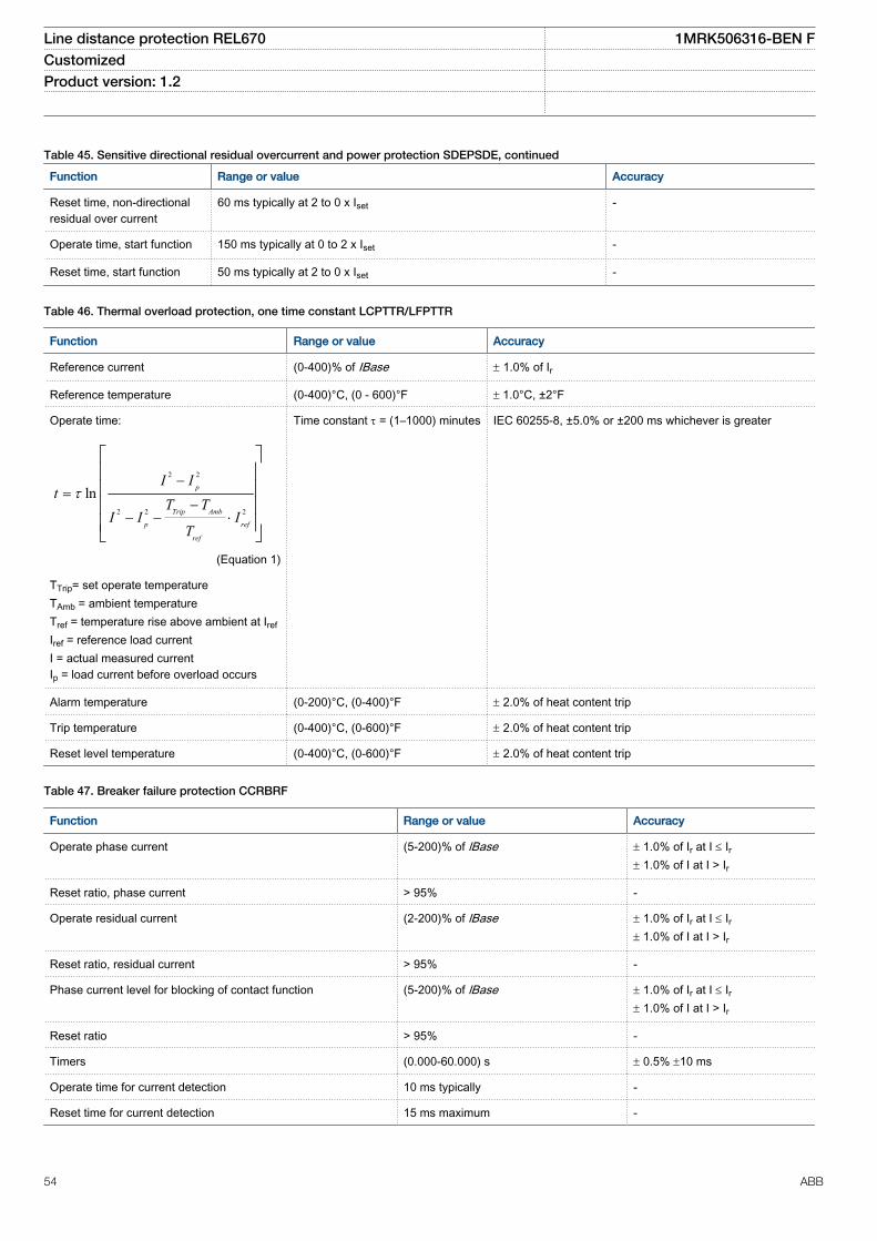
Table 45. Sensitive directional residual overcurrent and power protection SDEPSDE, continued
Function Range or value Accuracy
Reset time, non-directionalresidual over current
60 ms typically at 2 to 0 x Iset -
Operate time, start function 150 ms typically at 0 to 2 x Iset -
Reset time, start function 50 ms typically at 2 to 0 x Iset -
Table 46. Thermal overload protection, one time constant LCPTTR/LFPTTR
Function Range or value Accuracy
Reference current (0-400)% of IBase ± 1.0% of Ir
Reference temperature (0-400)°C, (0 - 600)°F ± 1.0°C, ±2°F
Operate time:
2 2
2 2 2
ln p
Trip Amb
p ref
ref
I It
T TI I I
T
t-
=-
- - ×
é ùê úê úê úê úë û
EQUATION13000039 V2 EN (Equation 1)
TTrip= set operate temperatureTAmb = ambient temperatureTref = temperature rise above ambient at Iref
Iref = reference load currentI = actual measured currentIp = load current before overload occurs
Time constant t = (1–1000) minutes IEC 60255-8, ±5.0% or ±200 ms whichever is greater
Alarm temperature (0-200)°C, (0-400)°F ± 2.0% of heat content trip
Trip temperature (0-400)°C, (0-600)°F ± 2.0% of heat content trip
Reset level temperature (0-400)°C, (0-600)°F ± 2.0% of heat content trip
Table 47. Breaker failure protection CCRBRF
Function Range or value Accuracy
Operate phase current (5-200)% of lBase ± 1.0% of Ir at I £ Ir± 1.0% of I at I > Ir
Reset ratio, phase current > 95% -
Operate residual current (2-200)% of lBase ± 1.0% of Ir at I £ Ir± 1.0% of I at I > Ir
Reset ratio, residual current > 95% -
Phase current level for blocking of contact function (5-200)% of lBase ± 1.0% of Ir at I £ Ir± 1.0% of I at I > Ir
Reset ratio > 95% -
Timers (0.000-60.000) s ± 0.5% ±10 ms
Operate time for current detection 10 ms typically -
Reset time for current detection 15 ms maximum -
Line distance protection REL670 1MRK506316-BEN FCustomized Product version: 1.2
54 ABB

Table 48. Stub protection STBPTOC
Function Range or value Accuracy
Operating current (1-2500)% of IBase ± 1.0% of Ir at I £ Ir± 1.0% of I at I > Ir
Reset ratio > 95% -
Definite time (0.000-60.000) s ± 0.5% ± 10 ms
Operate time, start function 20 ms typically at 0 to 2 x Iset -
Reset time, startfunction 25 ms typically at 2 to 0 x Iset -
Critical impulse time 10 ms typically at 0 to 2 x Iset -
Impulse margin time 15 ms typically -
Table 49. Pole discordance protection CCRPLD
Function Range or value Accuracy
Operate current (0–100)% of IBase ± 1.0% of Ir
Time delay (0.000-60.000) s ± 0.5% ± 10 ms
Table 50. Directional underpower protection GUPPDUP
Function Range or value Accuracy
Power level (0.0–500.0)% of SBase At low setting:(0.5-2.0)% of SBase(2.0-10)% of SBase
± 1.0% of Sr at S < Sr
± 1.0% of S at S > Sr
< ± 50% of set value< ± 20% of set value
Characteristic angle (-180.0–180.0) degrees 2 degrees
Timers (0.00-6000.00) s ± 0.5% ± 10 ms
Table 51. Directional overpower protection GOPPDOP
Function Range or value Accuracy
Power level (0.0–500.0)% of Sbase
At low setting:(0.5-2.0)% of Sbase
(2.0-10)% of Sbase
± 1.0% of Sr at S < Sr
± 1.0% of S at S > Sr
< ± 50% of set value< ± 20% of set value
Characteristic angle (-180.0–180.0) degrees 2 degrees
Timers (0.00-6000.00) s ± 0.5% ± 10 ms
Table 52. Broken conductor check BRCPTOC
Function Range or value Accuracy
Minimum phase current for operation (5–100)% of IBase ± 0.1% of Ir
Unbalance current operation (0–100)% of maximum current ± 0.1% of Ir
Timer (0.00-6000.00) s ± 0.5% ± 10 ms
Line distance protection REL670 1MRK506316-BEN FCustomized Product version: 1.2
ABB 55

Voltage protection
Table 53. Two step undervoltage protection UV2PTUV
Function Range or value Accuracy
Operate voltage, low and high step (1–100)% of UBase ± 0.5% of Ur
Absolute hysteresis (0–100)% of UBase ± 0.5% of Ur
Internal blocking level, step 1 and step 2 (1–100)% of UBase ± 0.5% of Ur
Inverse time characteristics for step 1 and step 2, see table 126 - See table 126
Definite time delay, step 1 (0.00 - 6000.00) s ± 0.5% ± 10 ms
Definite time delays (0.000-60.000) s ± 0.5% ±10 ms
Minimum operate time, inverse characteristics (0.000–60.000) s ± 0.5% ± 10 ms
Operate time, start function 25 ms typically at 2 x Uset to 0 -
Reset time, start function 25 ms typically at 0 to 2 x Uset -
Critical impulse time 10 ms typically at 2 x Uset to 0 -
Impulse margin time 15 ms typically -
Table 54. Two step overvoltage protection OV2PTOV
Function Range or value Accuracy
Operate voltage, step 1 and 2 (1-200)% of UBase ± 0.5% of Ur at U < Ur
± 0.5% of U at U > Ur
Absolute hysteresis (0–100)% of UBase ± 0.5% of Ur at U < Ur
± 0.5% of U at U > Ur
Inverse time characteristics for steps 1 and 2, see table 125 - See table 125
Definite time delay, step 1 (0.00 - 6000.00) s ± 0.5% ± 10 ms
Definite time delays (0.000-60.000) s ± 0.5% ± 10 ms
Minimum operate time, Inverse characteristics (0.000-60.000) s ± 0.5% ± 10 ms
Operate time, start function 25 ms typically at 0 to 2 x Uset -
Reset time, start function 25 ms typically at 2 to 0 x Uset -
Critical impulse time 10 ms typically at 0 to 2 x Uset -
Impulse margin time 15 ms typically -
Line distance protection REL670 1MRK506316-BEN FCustomized Product version: 1.2
56 ABB

Table 55. Two step residual overvoltage protection ROV2PTOV
Function Range or value Accuracy
Operate voltage, step 1 and step 2 (1-200)% of UBase ± 0.5% of Ur at U < Ur
± 1.0% of U at U > Ur
Absolute hysteresis (0–100)% of UBase ± 0.5% of Ur at U < Ur
± 1.0% of U at U > Ur
Inverse time characteristics for low and high step, see table 127 - See table 127
Definite time setting, step 1 (0.00–6000.00) s ± 0.5% ± 10 ms
Definite time setting (0.000–60.000) s ± 0.5% ± 10 ms
Minimum operate time (0.000-60.000) s ± 0.5% ± 10 ms
Operate time, start function 25 ms typically at 0 to 2 x Uset -
Reset time, start function 25 ms typically at 2 to 0 x Uset -
Critical impulse time 10 ms typically at 0 to 2 x Uset -
Impulse margin time 15 ms typically -
Table 56. Overexcitation protection OEXPVPH
Function Range or value Accuracy
Operate value, start (100–180)% of (UBase/frated) ± 0.5% of U
Operate value, alarm (50–120)% of start level ± 0.5% of Ur at U ≤ Ur
± 0.5% of U at U > Ur
Operate value, high level (100–200)% of (UBase/frated) ± 0.5% of U
Curve type IEEE or customer defined
2
(0.18 ):
( 1)k
IEEE tM
×=
-
EQUATION1319 V1 EN (Equation 2)
where M = (E/f)/(Ur/fr)
± 5% + 40 ms
Minimum time delay for inversefunction
(0.000–60.000) s ± 0.5% ± 10 ms
Maximum time delay for inversefunction
(0.00–9000.00) s ± 0.5% ± 10 ms
Alarm time delay (0.00–9000.00) ± 0.5% ± 10 ms
Table 57. Voltage differential protection VDCPTOV
Function Range or value Accuracy
Voltage difference for alarm andtrip
(0.0–100.0) % of UBase ± 0.5 % of Ur
Under voltage level (0.0–100.0) % of UBase ± 0.5% of Ur
Timers (0.000–60.000)s ± 0.5% ± 10 ms
Line distance protection REL670 1MRK506316-BEN FCustomized Product version: 1.2
ABB 57

Table 58. Loss of voltage check LOVPTUV
Function Range or value Accuracy
Operate voltage (0–100)% of UBase ± 0.5% of Ur
Pulse timer (0.050–60.000) s ± 0.5% ± 10 ms
Timers (0.000–60.000) s ± 0.5% ± 10 ms
Line distance protection REL670 1MRK506316-BEN FCustomized Product version: 1.2
58 ABB

Frequency protection
Table 59. Underfrequency protection SAPTUF
Function Range or value Accuracy
Operate value, start function (35.00-75.00) Hz ± 2.0 mHz
Operate time, start function 100 ms typically -
Reset time, start function 100 ms typically -
Operate time, definite time function (0.000-60.000)s ± 0.5% ± 10 ms
Reset time, definite time function (0.000-60.000)s ± 0.5% ± 10 ms
Voltage dependent time delay
( )ExponentU UMin
t tMax tMin tMinUNom UMin
-= × - +
-é ùê úë û
EQUATION1182 V1 EN (Equation 3)
U=Umeasured
Settings:UNom=(50-150)% of Ubase
UMin=(50-150)% of Ubase
Exponent=0.0-5.0tMax=(0.000-60.000)stMin=(0.000-60.000)s
5% + 200 ms
Table 60. Overfrequency protection SAPTOF
Function Range or value Accuracy
Operate value, start function (35.00-75.00) Hz ± 2.0 mHz atsymmetrical three-phase voltage
Operate time, start function 100 ms typically at fset -0.5 Hz to fset +0.5 Hz -
Reset time, start function 100 ms typically -
Operate time, definite time function (0.000-60.000)s ± 0.5% ± 10 ms
Reset time, definite time function (0.000-60.000)s ± 0.5% ± 10 ms
Table 61. Rate-of-change frequency protection SAPFRC
Function Range or value Accuracy
Operate value, start function (-10.00-10.00) Hz/s ± 10.0 mHz/s
Operate value, internal blocking level (0-100)% of UBase ± 0.5% of Ur
Operate time, start function 100 ms typically -
Line distance protection REL670 1MRK506316-BEN FCustomized Product version: 1.2
ABB 59

Multipurpose protection
Table 62. General current and voltage protection CVGAPC
Function Range or value Accuracy
Measuring current input phase1, phase2, phase3, PosSeq,NegSeq, 3*ZeroSeq, MaxPh, MinPh,UnbalancePh, phase1-phase2, phase2-phase3, phase3-phase1, MaxPh-Ph,MinPh-Ph, UnbalancePh-Ph
-
Base current (1 - 99999) A -
Measuring voltage input phase1, phase2, phase3, PosSeq, -NegSeq, -3*ZeroSeq, MaxPh, MinPh,UnbalancePh, phase1-phase2, phase2-phase3, phase3-phase1, MaxPh-Ph,MinPh-Ph, UnbalancePh-Ph
-
Base voltage (0.05 - 2000.00) kV -
Start overcurrent, step 1 and 2 (2 - 5000)% of IBase ± 1.0% of Ir for I<Ir± 1.0% of I for I>Ir
Start undercurrent, step 1 and 2 (2 - 150)% of IBase ± 1.0% of Ir for I<Ir± 1.0% of I for I>Ir
Definite time delay (0.00 - 6000.00) s ± 0.5% ± 10 ms
Operate time start overcurrent 25 ms typically at 0 to 2 x Iset -
Reset time start overcurrent 25 ms typically at 2 to 0 x Iset -
Operate time start undercurrent 25 ms typically at 2 to 0 x Iset -
Reset time start undercurrent 25 ms typically at 0 to 2 x Iset -
See table 122 and table 123 Parameter ranges for customer definedcharacteristic no 17:k: 0.05 - 999.00A: 0.0000 - 999.0000B: 0.0000 - 99.0000C: 0.0000 - 1.0000P: 0.0001 - 10.0000PR: 0.005 - 3.000TR: 0.005 - 600.000CR: 0.1 - 10.0
See table 122 and table 123
Voltage level where voltage memory takes over (0.0 - 5.0)% of UBase ± 0.5% of Ur
Start overvoltage, step 1 and 2 (2.0 - 200.0)% of UBase ± 0.5% of Ur for U<Ur
± 0.5% of U for U>Ur
Start undervoltage, step 1 and 2 (2.0 - 150.0)% of UBase ± 0.5% of Ur for U<Ur
± 0.5% of U for U>Ur
Operate time, start overvoltage 25 ms typically at 0 to 2 x Uset -
Reset time, start overvoltage 25 ms typically at 2 to 0 x Uset -
Operate time start undervoltage 25 ms typically 2 to 0 x Uset -
Reset time start undervoltage 25 ms typically at 0 to 2 x Uset -
High and low voltage limit, voltage dependent operation (1.0 - 200.0)% of UBase ± 1.0% of Ur for U<Ur
± 1.0% of U for U>Ur
Directional function Settable: NonDir, forward and reverse -
Line distance protection REL670 1MRK506316-BEN FCustomized Product version: 1.2
60 ABB

Table 62. General current and voltage protection CVGAPC , continued
Function Range or value Accuracy
Relay characteristic angle (-180 to +180) degrees ± 2.0 degrees
Relay operate angle (1 to 90) degrees ± 2.0 degrees
Reset ratio, overcurrent > 95% -
Reset ratio, undercurrent < 105% -
Reset ratio, overvoltage > 95% -
Reset ratio, undervoltage < 105% -
Overcurrent:
Critical impulse time 10 ms typically at 0 to 2 x Iset -
Impulse margin time 15 ms typically -
Undercurrent:
Critical impulse time 10 ms typically at 2 to 0 x Iset -
Impulse margin time 15 ms typically -
Overvoltage:
Critical impulse time 10 ms typically at 0 to 2 x Uset -
Impulse margin time 15 ms typically -
Undervoltage:
Critical impulse time 10 ms typically at 2 to 0 x Uset -
Impulse margin time 15 ms typically -
Line distance protection REL670 1MRK506316-BEN FCustomized Product version: 1.2
ABB 61

Secondary system supervision
Table 63. Current circuit supervision CCSRDIF
Function Range or value Accuracy
Operate current (5-200)% of Ir ± 10.0% of Ir at I £ Ir± 10.0% of I at I > Ir
Block current (5-500)% of Ir ± 5.0% of Ir at I £ Ir± 5.0% of I at I > Ir
Table 64. Fuse failure supervision SDDRFUF
Function Range or value Accuracy
Operate voltage, zero sequence (1-100)% of UBase ± 1.0% of Ur
Operate current, zero sequence (1–100)% of IBase ± 1.0% of Ir
Operate voltage, negative sequence (1–100)% of UBase ± 0.5% of Ur
Operate current, negative sequence (1–100)% of IBase ± 1.0% of Ir
Operate voltage change level (1–100)% of UBase ± 5.0% of Ur
Operate current change level (1–100)% of IBase ± 5.0% of Ir
Operate phase voltage (1-100)% of UBase ± 0.5% of Ur
Operate phase current (1-100)% of IBase ± 1.0% of Ir
Operate phase dead line voltage (1-100)% of UBase ± 0.5% of Ur
Operate phase dead line current (1-100)% of IBase ± 1.0% of Ir
Operate time, general start of function 25 ms typically at 1 to 0 of Ubase -
Reset time, general start of function 35 ms typically at 0 to 1 of Ubase -
Line distance protection REL670 1MRK506316-BEN FCustomized Product version: 1.2
62 ABB

Control
Table 65. Synchronizing, synchrocheck and energizing check SESRSYN
Function Range or value Accuracy
Phase shift, jline - jbus (-180 to 180) degrees -
Voltage ratio, Ubus/Uline 0.500 - 2.000 -
Voltage high limit for synchronizing and synchrocheck (50.0-120.0)% of UBaseBus andUBaseLIne
± 0.5% of Ur at U ≤ Ur
± 0.5% of U at U >Ur
Reset ratio, synchrocheck > 95% -
Frequency difference limit between bus and line for synchrocheck (0.003-1.000) Hz ± 2.0 mHz
Phase angle difference limit between bus and line for synchrocheck (5.0-90.0) degrees ± 2.0 degrees
Voltage difference limit between bus and line for synchronizing andsynchrocheck
(0.02-0.5) p.u ± 0.5% of Ur
Time delay output for synchrocheck (0.000-60.000) s ± 0.5% ± 10 ms
Frequency difference minimum limit for synchronizing (0.003-0.250) Hz ± 2.0 mHz
Frequency difference maximum limit for synchronizing (0.050-0.500) Hz ± 2.0 mHz
Maximum allowed frequency rate of change (0.000-0.500) Hz/s ± 10.0 mHz/s
Closing time of the breaker (0.000-60.000) s ± 0.5% ± 10 ms
Breaker closing pulse duration (0.000-60.000) s ± 0.5% ± 10 ms
tMaxSynch, which resets synchronizing function if no close has beenmade before set time
(0.000-60.000) s ± 0.5% ± 10 ms
Minimum time to accept synchronizing conditions (0.000-60.000) s ± 0.5% ± 10 ms
Voltage high limit for energizing check (50.0-120.0)% of UBaseBus andUBaseLIne
± 0.5% of Ur at U ≤ Ur
± 0.5% of U at U >Ur
Reset ratio, voltage high limit > 95% -
Voltage low limit for energizing check (10.0-80.0)% of UBaseBus andUBaseLine
± 0.5% of Ur
Reset ratio, voltage low limit < 105% -
Maximum voltage for energizing (50.0-180.0)% of UBaseBus and/or UBaseLIne
± 0.5% of Ur at U ≤ Ur
± 0.5% of U at U >Ur
Time delay for energizing check (0.000-60.000) s ± 0.5% ± 10 ms
Operate time for synchrocheck function 160 ms typically -
Operate time for energizing function 80 ms typically -
Line distance protection REL670 1MRK506316-BEN FCustomized Product version: 1.2
ABB 63

Table 66. Autorecloser SMBRREC
Function Range or value Accuracy
Number of autoreclosing shots 1 - 5 -
Autoreclosing open time:shot 1 - t1 1Phshot 1 - t1 2Phshot 1 - t1 3PhHSshot 1 - t1 3PhDld
(0.000-60.000) s
± 0.5% ± 10 ms
shot 2 - t2shot 3 - t3shot 4 - t4shot 5 - t5
(0.00-6000.00) s
Extended autorecloser open time (0.000-60.000) s
Autorecloser maximum wait time for sync (0.00-6000.00) s
Maximum trip pulse duration (0.000-60.000) s
Inhibit reset time (0.000-60.000) s
Reclaim time (0.00-6000.00) s
Minimum time CB must be closed before AR becomes ready for autoreclosing cycle (0.00-6000.00) s
Circuit breaker closing pulse length (0.000-60.000) s
CB check time before unsuccessful (0.00-6000.00) s
Wait for master release (0.00-6000.00) s
Wait time after close command before proceeding to next shot (0.000-60.000) s
Line distance protection REL670 1MRK506316-BEN FCustomized Product version: 1.2
64 ABB

Scheme communication
Table 67. Scheme communication logic for distance or overcurrent protection ZCPSCH
Function Range or value Accuracy
Scheme type IntertripPermissive UnderreachPermissive OverreachBlocking
-
Co-ordination time for blockingcommunication scheme
(0.000-60.000) s ± 0.5% ± 10 ms
Minimum duration of a send signal (0.000-60.000) s ± 0.5% ± 10 ms
Security timer for loss of guardsignal detection
(0.000-60.000) s ± 0.5% ± 10 ms
Operation mode of unblocking logic OffNoRestartRestart
-
Table 68. Phase segregated scheme communication logic for distance protection ZC1PPSCH
Function Range or value Accuracy
Scheme type IntertripPermissive URPermissive ORBlocking
-
Co-ordination time for blockingcommunication scheme
(0.000-60.000) s ± 0.5% ± 10 ms
Minimum duration of a carrier sendsignal
(0.000-60.000) s ± 0.5% ± 10 ms
Security timer for loss of carrierguard detection
(0.000-60.000) s ± 0.5% ± 10 ms
Operation mode of unblocking logic OffNoRestartRestart
-
Table 69. Current reversal and weak-end infeed logic for distance protection ZCRWPSCH
Function Range or value Accuracy
Detection levelphase-to-neutralvoltage
(10-90)% of UBase ± 0.5% of Ur
Detection level phase-to-phasevoltage
(10-90)% of UBase ± 0.5% of Ur
Reset ratio <105% -
Operate time for current reversallogic
(0.000-60.000) s ± 0.5% ± 10 ms
Delay time for current reversal (0.000-60.000) s ± 0.5% ± 10 ms
Coordination time for weak-endinfeed logic
(0.000-60.000) s ± 0.5% ± 10 ms
Line distance protection REL670 1MRK506316-BEN FCustomized Product version: 1.2
ABB 65

Table 70. Current reversal and weak-end infeed logic for phase segregated communication ZC1WPSCH
Function Range or value Accuracy
Detection level phase to neutralvoltage
(10-90)% of UBase ± 0.5% of Ur
Detection level phase to phasevoltage
(10-90)% of UBase ± 0.5% of Ur
Reset ratio <105% -
Operate time for current reversal (0.000-60.000) s ± 0.5% ± 10 ms
Delay time for current reversal (0.000-60.000) s ± 0.5% ± 10 ms
Coordination time for weak-endinfeed logic
(0.000-60.000) s ± 0.5% ± 10 ms
Table 71. Scheme communication logic for residual overcurrent protection ECPSCH
Function Range or value Accuracy
Scheme type Permissive UnderreachingPermissive OverreachingBlocking
-
Communication schemecoordination time
(0.000-60.000) s ± 0.5% ± 10 ms
Table 72. Current reversal and weak-end infeed logic for residual overcurrent protection ECRWPSCH
Function Range or value Accuracy
Operating mode of WEI logic OffEchoEcho & Trip
-
Operate voltage 3Uo for WEI trip (5-70)% of UBase ± 0.5% of Ur
Reset ratio >95% -
Operate time for current reversallogic
(0.000-60.000) s ± 0.5% ± 10 ms
Delay time for current reversal (0.000-60.000) s ± 0.5% ± 10 ms
Coordination time for weak-endinfeed logic
(0.000–60.000) s ± 0.5% ± 10 ms
Line distance protection REL670 1MRK506316-BEN FCustomized Product version: 1.2
66 ABB

Direct transfer trip
Table 73. Low active power and power factor protection LAPPGAPC
Function Range or value Accuracy
Operate value, low active power (2.0-100.0)% of SBase ± 1,0% of Sr
Reset ratio, low active power <105% -
Transient overreach, low active power <20 % at τ = 100 ms -
Operate value, low power factor 0.00-1.00 ± 1,0% of Sr
Reset ratio, low power factor <105% -
Transient overreach, low power factor <20 % at τ = 100 ms -
Timers (0.000-60.000) s ± 0.5% ± 10 ms
Critical impulse time, low active power 10 ms typically at 1.2 to 0.8xPset -
Impulse margin time, low active power 10 ms typically -
Table 74. Compensated over- and undervoltage protection COUVGAPC
Function Range or value Accuracy
Operate value, undervoltage (1-100)% of UBase ± 0,5% of Ur
Reset ratio, undervoltage <105% -
Critical impulse time, undervoltage 5 ms typically at 1.2 to 0.8xUset -
Impulse margin time, undervoltage 15 ms typically -
Operate value, overvoltage (1-200)% of UBase ± 0.5% of Ur at U<Ur
± 0.5% of U at U>Ur
Reset ratio, overvoltage >95% -
Critical impulse time, overvoltage 2 ms typically at 0.8 to 1.2xUset -
Impulse margin time, overvoltage 10 ms typically -
Timers (0.000-60.000) s ± 0.5% ± 10 ms
Table 75. Sudden change in current variation SCCVPTOC
Function Range or value Accuracy
Operate value, overcurrent (0 - 100)% of IBase ± 1,0% of Ir
Reset ratio, overcurrent >95% -
Timers (0.000-60.000) s ± 0.5% ± 10 ms
Table 76. Carrier receive logic LCCRPTRC
Function Range or value Accuracy
Operation mode 1 Out Of 22 Out Of 2
-
Timer (0.000-60.000) s ± 0.5% ± 10 ms
Line distance protection REL670 1MRK506316-BEN FCustomized Product version: 1.2
ABB 67

Table 77. Negative sequence overvoltage protection LCNSPTOV
Function Range or value Accuracy
Operate value, negative sequence overvoltage (1-200)% of UBase ± 0.5% of Ur at U<Ur
± 0.5% of U at U>Ur
Reset ratio, negative sequence overvoltage >95% -
Operate time, start 20 ms typically at 0 to 2xUset -
Reset time, start 25 ms typically at 2 to 0xUset -
Critical impulse time, negative sequence overvoltage 10 ms typically at 0 to 2xUset -
Impulse margin time, negative sequence overvoltage 15 ms typically -
Timers (0.000-120.000) s ± 0.5% ± 10 ms
Table 78. Zero sequence overvoltage protection LCZSPTOV
Function Range or value Accuracy
Operate value, zero sequence overvoltage (1-200)% of UBase ± 0.5% of Ur at U<Ur
± 0.5% of U at U>Ur
Reset ratio, zero sequence overvoltage >95% -
Operate time, start 25 ms typically at 0 to 1.5xUset -
Reset time, start 25 ms typically at 1.5 to 0xUset -
Critical impulse time, zero sequence overvoltage 10 ms typically at 0 to 1.5xUset -
Timers (0.000-120.000) s ± 0.5% ± 10 ms
Table 79. Negative sequence overcurrent protection LCNSPTOC
Function Range or value Accuracy
Operate value, negative sequence overcurrent (1 - 2500)% of IBase ± 1.0% of Ir at I < Ir± 1.0% of I at I > Ir
Reset ratio, negative sequence overcurrent >95% -
Operate time, start 20 ms typically at 0 to 2xIset
15 ms typically at 0 to 10xIset
-
Reset time, start 25 ms typically at 2 to 0xIset -
Critical impulse time, negative sequence overcurrent 10 ms typically at 0 to 2xIset
2 ms typically at 0 to 10xIset
-
Impulse margin time, negative sequence overcurrent 10 ms typically -
Timer (0.000-60.000) s ± 0.5% ± 10 ms
Transient overreach, start function <5% at τ = 100 ms -
Line distance protection REL670 1MRK506316-BEN FCustomized Product version: 1.2
68 ABB

Table 80. Zero sequence overcurrent protection LCZSPTOC
Function Range or value Accuracy
Operate value, zero sequence overcurrent (1-2500)% of IBase ± 1.0% of Ir at I<Ir± 1.0% of I at I>Ir
Reset ratio, zero sequence overcurrent >95% -
Operate time, start 20 ms typically at 0 to 2xIset
15 ms typically at 0 to 10xIset
-
Reset time, start 30 ms typically at 2 to 0xIset -
Critical impulse time, zero sequence overcurrent 10 ms typically at 0 to 2xIset
2 ms typically at 0 to 10xIset
-
Impulse margin time, zero sequence overcurrent 15 ms typically -
Timer (0.000-60.000) s ± 0.5% ± 10 ms
Table 81. Three phase overcurrent LCP3PTOC
Function Range or value Accuracy
Operate value, overcurrent (5-2500)% of IBase ± 1.0% of Ir at I < Ir± 1.0% of I at I > Ir
Reset ratio, overcurrent >95% -
Operate time, start 20 ms typically at 0 to 2xIset
15 ms typically at 0 to 10xIset
-
Reset time, start 30 ms typically at 2 to 0xIset -
Critical impulse time, overcurrent 5 ms typically at 0 to 2xIset
2 ms typically at 0 to 10xIset
-
Impulse margin time, overcurrent 10 ms typically -
Timers (0.000-60.000) s ± 0.5% ± 10 ms
Table 82. Three phase undercurrent LCP3TUC
Function Range or value Accuracy
Operate value, undercurrent (1.00-100.00)% of IBase ± 1.0% of Ir
Reset ratio, undercurrent >105% -
Operate time, start 20 ms typically at 2 to 0xIset -
Reset time, start 30 ms typically at 0 to 2xIset -
Critical impulse time, undercurrent 10 ms typically at 2 to 0xIset -
Impulse margin time, undercurrent 10 ms typically -
Timers (0.000-60.000) s ± 0.5% ± 10 ms
Line distance protection REL670 1MRK506316-BEN FCustomized Product version: 1.2
ABB 69

Logic
Table 83. Tripping logic SMPPTRC
Function Range or value Accuracy
Trip action 3-ph, 1/3-ph, 1/2/3-ph -
Minimum trip pulse length (0.000-60.000) s ± 0.5% ± 10 ms
Timers (0.000-60.000) s ± 0.5% ± 10 ms
Table 84. Configurable logic blocks
Logic block Quantity with cycle time Range or value Accuracy
fast medium normal
LogicAND 60 60 160 - -
LogicOR 60 60 160 - -
LogicXOR 10 10 20 - -
LogicInverter 30 30 80 - -
LogicSRMemory 10 10 20 - -
LogicRSMemory 10 10 20 - -
LogicGate 10 10 20 - -
LogicTimer 10 10 20 (0.000–90000.000) s ± 0.5% ± 10 ms
LogicPulseTimer 10 10 20 (0.000–90000.000) s ± 0.5% ± 10 ms
LogicTimerSet 10 10 20 (0.000–90000.000) s ± 0.5% ± 10 ms
LogicLoopDelay 10 10 20 (0.000–90000.000) s ± 0.5% ± 10 ms
Trip Matrix Logic 6 6 - - -
Boolean 16 to Integer 4 4 8 - -
Boolean 16 to integerwith Logic Node
4 4 8 - -
Integer to Boolean 16 4 4 8 - -
Integer to Boolean 16with Logic Node
4 4 8 - -
Line distance protection REL670 1MRK506316-BEN FCustomized Product version: 1.2
70 ABB

Monitoring
Table 85. Measurements CVMMXN
Function Range or value Accuracy
Frequency (0.95-1.05) × fr ± 2.0 mHz
Voltage (0.1-1.5) ×Ur ± 0.5% of Ur at U£Ur
± 0.5% of U at U > Ur
Connected current (0.2-4.0) × Ir ± 0.5% of Ir at I £ Ir± 0.5% of I at I > Ir
Active power, P 0.1 x Ur< U < 1.5 x Ur
0.2 x Ir < I < 4.0 x Ir± 1.0% of Sr at S ≤ Sr
± 1.0% of S at S > Sr
Conditions:0.8 x Ur < U < 1.2 Ur
0.2 x Ir < I < 1.2 Ir
Reactive power, Q 0.1 x Ur< U < 1.5 x Ur
0.2 x Ir < I < 4.0 x Ir
Apparent power, S 0.1 x Ur < U < 1.5 x Ur
0.2 x Ir< I < 4.0 x Ir
Power factor, cos (φ) 0.1 x Ur < U < 1.5 x Ur
0.2 x Ir< I < 4.0 x Ir± 0.02
Table 86. Phase current measurement CMMXU
Function Range or value Accuracy
Current (0.1-4.0) × Ir ± 0.2% of Ir at I ≤ 0.5 × Ir± 0.2% of I at I > 0.5 × Ir
Phase angle (0.1–4.0) x Ir ± 0.5° at 0.2 × Ir < I < 0.5 × Ir± 0.2° at 0.5 × Ir ≤ I < 4.0 × Ir
Table 87. Phase-phase voltage measurement VMMXU
Function Range or value Accuracy
Voltage (10 to 300) V ± 0.3% of U at U ≤ 50 V± 0.2% of U at U > 50 V
Phase angle (10 to 300) V ± 0.3° at U ≤ 50 V± 0.2° at U > 50 V
Table 88. Phase-neutral voltage measurement VNMMXU
Function Range or value Accuracy
Voltage (10 to 300) V ± 0.3% of U at U ≤ 50 V± 0.2% of U at U > 50 V
Phase angle (10 to 300) V ± 0.3° at U ≤ 50 V± 0.2° at U > 50 V
Line distance protection REL670 1MRK506316-BEN FCustomized Product version: 1.2
ABB 71

Table 89. Current sequence component measurement CMSQI
Function Range or value Accuracy
Current positive sequence, I1Three phase settings
(0.1–4.0) × Ir ± 0.2% of Ir at I ≤ 0.5 × Ir± 0.2% of I at I > 0.5 × Ir
Current zero sequence, 3I0Three phase settings
(0.1–1.0) × Ir ± 0.2% of Ir at I ≤ 0.5 × Ir± 0.2% of I at I > 0.5 × Ir
Current negative sequence, I2Three phase settings
(0.1–1.0) × Ir ± 0.2% of Ir at I ≤ 0.5 × Ir± 0.2% of I at I > 0.5 × Ir
Phase angle (0.1–4.0) × Ir ± 0.5° at 0.2 × Ir < I < 0.5 × Ir± 0.2° at 0.5 × Ir ≤ I < 4.0 × Ir
Table 90. Voltage sequence measurement VMSQI
Function Range or value Accuracy
Voltage positive sequence, U1 (10 to 300) V ± 0.3% of U at U ≤ 50 V± 0.2% of U at U > 50 V
Voltage zero sequence, 3U0 (10 to 300) V ± 0.3% of U at U ≤ 50 V± 0.2% of U at U > 50 V
Voltage negative sequence, U2 (10 to 300) V ± 0.3% of U at U ≤ 50 V± 0.2% of U at U > 50 V
Phase angle (10 to 300) V ± 0.3° at U ≤ 50 V± 0.2° at U > 50 V
Table 91. Supervision of mA input signals
Function Range or value Accuracy
mA measuring function ± 5, ± 10, ± 20 mA0-5, 0-10, 0-20, 4-20 mA
± 0.1 % of set value ± 0.005 mA
Max current of transducer toinput
(-20.00 to +20.00) mA
Min current of transducer toinput
(-20.00 to +20.00) mA
Alarm level for input (-20.00 to +20.00) mA
Warning level for input (-20.00 to +20.00) mA
Alarm hysteresis for input (0.0-20.0) mA
Table 92. Event counter CNTGGIO
Function Range or value Accuracy
Counter value 0-100000 -
Max. count up speed 10 pulses/s (50% duty cycle) -
Line distance protection REL670 1MRK506316-BEN FCustomized Product version: 1.2
72 ABB

Table 93. Disturbance report DRPRDRE
Function Range or value Accuracy
Pre-fault time (0.05–9.90) s -
Post-fault time (0.1–10.0) s -
Limit time (0.5–10.0) s -
Maximum number of recordings 100, first in - first out -
Time tagging resolution 1 ms See table 118
Maximum number of analog inputs 30 + 10 (external + internallyderived)
-
Maximum number of binary inputs 96 -
Maximum number of phasors in the Trip Value recorder per recording 30 -
Maximum number of indications in a disturbance report 96 -
Maximum number of events in the Event recording per recording 150 -
Maximum number of events in the Event list 1000, first in - first out -
Maximum total recording time (3.4 s recording time and maximum number ofchannels, typical value)
340 seconds (100 recordings) at50 Hz, 280 seconds (80recordings) at 60 Hz
-
Sampling rate 1 kHz at 50 Hz1.2 kHz at 60 Hz
-
Recording bandwidth (5-300) Hz -
Table 94. Fault locator LMBRFLO
Function Value or range Accuracy
Reactive and resistive reach (0.001-1500.000) Ω/phase ± 2.0% static accuracy± 2.0% degrees static angular accuracyConditions:Voltage range: (0.1-1.1) x Ur
Current range: (0.5-30) x Ir
Phase selection According to input signals -
Maximum number of faultlocations
100 -
Table 95. Event list
Function Value
Buffer capacity Maximum number of events in the list 1000
Resolution 1 ms
Accuracy Depending on time synchronizing
Table 96. Indications
Function Value
Buffer capacity Maximum number of indications presented for single disturbance 96
Maximum number of recorded disturbances 100
Line distance protection REL670 1MRK506316-BEN FCustomized Product version: 1.2
ABB 73

Table 97. Event recorder
Function Value
Buffer capacity Maximum number of events in disturbance report 150
Maximum number of disturbance reports 100
Resolution 1 ms
Accuracy Depending on timesynchronizing
Table 98. Trip value recorder
Function Value
Buffer capacity
Maximum number of analog inputs 30
Maximum number of disturbance reports 100
Table 99. Disturbance recorder
Function Value
Buffer capacity Maximum number of analog inputs 40
Maximum number of binary inputs 96
Maximum number of disturbance reports 100
Maximum total recording time (3.4 s recording time and maximum numberof channels, typical value)
340 seconds (100 recordings) at 50 Hz280 seconds (80 recordings) at 60 Hz
Line distance protection REL670 1MRK506316-BEN FCustomized Product version: 1.2
74 ABB

Metering
Table 100. Pulse counter PCGGIO
Function Setting range Accuracy
Input frequency See Binary Input Module (BIM) -
Cycle time for report of countervalue
(1–3600) s -
Table 101. Energy metering ETPMMTR
Function Range or value Accuracy
Energy metering kWh Export/Import, kvarh Export/Import
Input from MMXU. No extra error at steady load
Line distance protection REL670 1MRK506316-BEN FCustomized Product version: 1.2
ABB 75

Station communication
Table 102. IEC 61850-8-1 communication protocol
Function Value
Protocol IEC 61850-8-1
Communication speed for the IEDs 100BASE-FX
Protocol IEC 608–5–103
Communication speed for the IEDs 9600 or 19200 Bd
Protocol DNP3.0
Communication speed for the IEDs 300–19200 Bd
Protocol TCP/IP, Ethernet
Communication speed for the IEDs 100 Mbit/s
Table 103. LON communication protocol
Function Value
Protocol LON
Communication speed 1.25 Mbit/s
Table 104. SPA communication protocol
Function Value
Protocol SPA
Communication speed 300, 1200, 2400, 4800, 9600, 19200 or 38400 Bd
Slave number 1 to 899
Table 105. IEC60870-5-103 communication protocol
Function Value
Protocol IEC 60870-5-103
Communication speed 9600, 19200 Bd
Table 106. SLM – LON port
Quantity Range or value
Optical connector Glass fibre: type STPlastic fibre: type HFBR snap-in
Fibre, optical budget Glass fibre: 11 dB (1000 m typically *)Plastic fibre: 7 dB (10 m typically *)
Fibre diameter Glass fibre: 62.5/125 mmPlastic fibre: 1 mm
*) depending on optical budget calculation
Line distance protection REL670 1MRK506316-BEN FCustomized Product version: 1.2
76 ABB

Table 107. SLM – SPA/IEC 60870-5-103/DNP3 port
Quantity Range or value
Optical connector Glass fibre: type STPlastic fibre: type HFBR snap-in
Fibre, optical budget Glass fibre: 11 dB (3000ft/1000 m typically *)Plastic fibre: 7 dB (80ft/25 m typically *)
Fibre diameter Glass fibre: 62.5/125 mmPlastic fibre: 1 mm
*) depending on optical budget calculation
Table 108. Galvanic X.21 line data communication module (X.21-LDCM)
Quantity Range or value
Connector, X.21 Micro D-sub, 15-pole male, 1.27 mm (0.050") pitch
Connector, ground selection 2 pole screw terminal
Standard CCITT X21
Communication speed 64 kbit/s
Insulation 1 kV
Maximum cable length 100 m
Table 109. Galvanic RS485 communication module
Quantity Range or value
Communication speed 2400–19200 bauds
External connectors RS-485 6-pole connectorSoft ground 2-pole connector
Table 110. IEC 62439-3 Edition 1 and Edition 2 parallel redundancy protocol
Function Value
Protocol IEC 61850-8-1
Communication speed 100 Base-FX
Line distance protection REL670 1MRK506316-BEN FCustomized Product version: 1.2
ABB 77

Remote communication
Table 111. Line data communication module
Characteristic Range or value
Type of LDCM Short range (SR) Medium range (MR) Long range (LR)
Type of fibre Graded-indexmultimode62.5/125 µm or50/125 µm
Singlemode 9/125 µm Singlemode 9/125 µm
Wave length 850 nm 1310 nm 1550 nm
Optical budgetGraded-index multimode 62.5/125 mm, Graded-index multimode 50/125 mm
13 dB (typicaldistance about 3km *)9 dB (typicaldistance about 2km *)
22 dB (typicaldistance 80 km *)
26 dB (typical distance 110 km *)
Optical connector Type ST Type FC/PC Type FC/PC
Protocol C37.94 C37.94implementation **)
C37.94 implementation **)
Data transmission Synchronous Synchronous Synchronous
Transmission rate / Data rate 2 Mb/s / 64 kbit/s 2 Mb/s / 64 kbit/s 2 Mb/s / 64 kbit/s
Clock source Internal or derivedfrom receivedsignal
Internal or derivedfrom received signal
Internal or derived from receivedsignal
*) depending on optical budget calculation**) C37.94 originally defined just for multimode; using same header, configuration and data format as C37.94
Line distance protection REL670 1MRK506316-BEN FCustomized Product version: 1.2
78 ABB

HardwareIED
Table 112. Case
Material Steel sheet
Front plate Steel sheet profile with cut-out for HMI
Surface treatment Aluzink preplated steel
Finish Light grey (RAL 7035)
Table 113. Water and dust protection level according to IEC 60529
Front IP40 (IP54 with sealing strip)
Sides, top and bottom IP20
Rear side IP20 with screw compression typeIP10 with ring lug terminals
Table 114. Weight
Case size Weight
6U, 1/2 x 19” £ 10 kg
6U, 3/4 x 19” £ 15 kg
6U, 1/1 x 19” £ 18 kg
Connection system
Table 115. CT and VT circuit connectors
Connector type Rated voltage and current Maximum conductor area
Screw compression type 250 V AC, 20 A 4 mm2 (AWG12)2 x 2.5 mm2 (2 x AWG14)
Terminal blocks suitable for ring lug terminals 250 V AC, 20 A 4 mm2 (AWG12)
Table 116. Binary I/O connection system
Connector type Rated voltage Maximum conductor area
Screw compression type 250 V AC 2.5 mm2 (AWG14)2 × 1 mm2 (2 x AWG18)
Terminal blocks suitable for ring lug terminals 300 V AC 3 mm2 (AWG14)
Line distance protection REL670 1MRK506316-BEN FCustomized Product version: 1.2
ABB 79

Basic IED functions
Table 117. Self supervision with internal event list
Data Value
Recording manner Continuous, event controlled
List size 40 events, first in-first out
Table 118. Time synchronization, time tagging
Function Value
Time tagging resolution, events and sampled measurement values 1 ms
Time tagging error with synchronization once/min (minute pulse synchronization), events and sampledmeasurement values
± 1.0 ms typically
Time tagging error with SNTP synchronization, sampled measurement values ± 1.0 ms typically
Table 119. GPS time synchronization module (GTM)
Function Range or value Accuracy
Receiver – ±1µs relative UTC
Time to reliable time reference with antenna in newposition or after power loss longer than 1 month
<30 minutes –
Time to reliable time reference after a power losslonger than 48 hours
<15 minutes –
Time to reliable time reference after a power lossshorter than 48 hours
<5 minutes –
Table 120. GPS – Antenna and cable
Function Value
Max antenna cable attenuation 26 db @ 1.6 GHz
Antenna cable impedance 50 ohm
Lightning protection Must be provided externally
Antenna cable connector SMA in receiver endTNC in antenna end
Accuracy +/-2μs
Line distance protection REL670 1MRK506316-BEN FCustomized Product version: 1.2
80 ABB

Table 121. IRIG-B
Quantity Rated value
Number of channels IRIG-B 1
Number of channels PPS 1
Electrical connector:
Electrical connector IRIG-B BNC
Pulse-width modulated 5 Vpp
Amplitude modulated– low level– high level
1-3 Vpp3 x low level, max 9 Vpp
Supported formats IRIG-B 00x, IRIG-B 12x
Accuracy +/-10μs for IRIG-B 00x and +/-100μs for IRIG-B 12x
Input impedance 100 k ohm
Optical connector:
Optical connector PPS and IRIG-B Type ST
Type of fibre 62.5/125 μm multimode fibre
Supported formats IRIG-B 00x, PPS
Accuracy +/- 2μs
Line distance protection REL670 1MRK506316-BEN FCustomized Product version: 1.2
ABB 81

Inverse characteristic
Table 122. ANSI Inverse time characteristics
Function Range or value Accuracy
Operating characteristic:
( )1= + ×
-
æ öç ÷ç ÷è ø
P
At B k
I
EQUATION1249-SMALL V1 EN
Reset characteristic:
( )2 1= ×
-
trt kI
EQUATION1250-SMALL V1 EN
I = Imeasured/Iset
k = (0.05-999) in steps of 0.01 -
ANSI Extremely Inverse A=28.2, B=0.1217, P=2.0 , tr=29.1 ANSI/IEEE C37.112, 5%+ 40 ms
ANSI Very inverse A=19.61, B=0.491, P=2.0 , tr=21.6
ANSI Normal Inverse A=0.0086, B=0.0185, P=0.02, tr=0.46
ANSI Moderately Inverse A=0.0515, B=0.1140, P=0.02, tr=4.85
ANSI Long Time Extremely Inverse A=64.07, B=0.250, P=2.0, tr=30
ANSI Long Time Very Inverse A=28.55, B=0.712, P=2.0, tr=13.46
ANSI Long Time Inverse A=0.086, B=0.185, P=0.02, tr=4.6
Line distance protection REL670 1MRK506316-BEN FCustomized Product version: 1.2
82 ABB
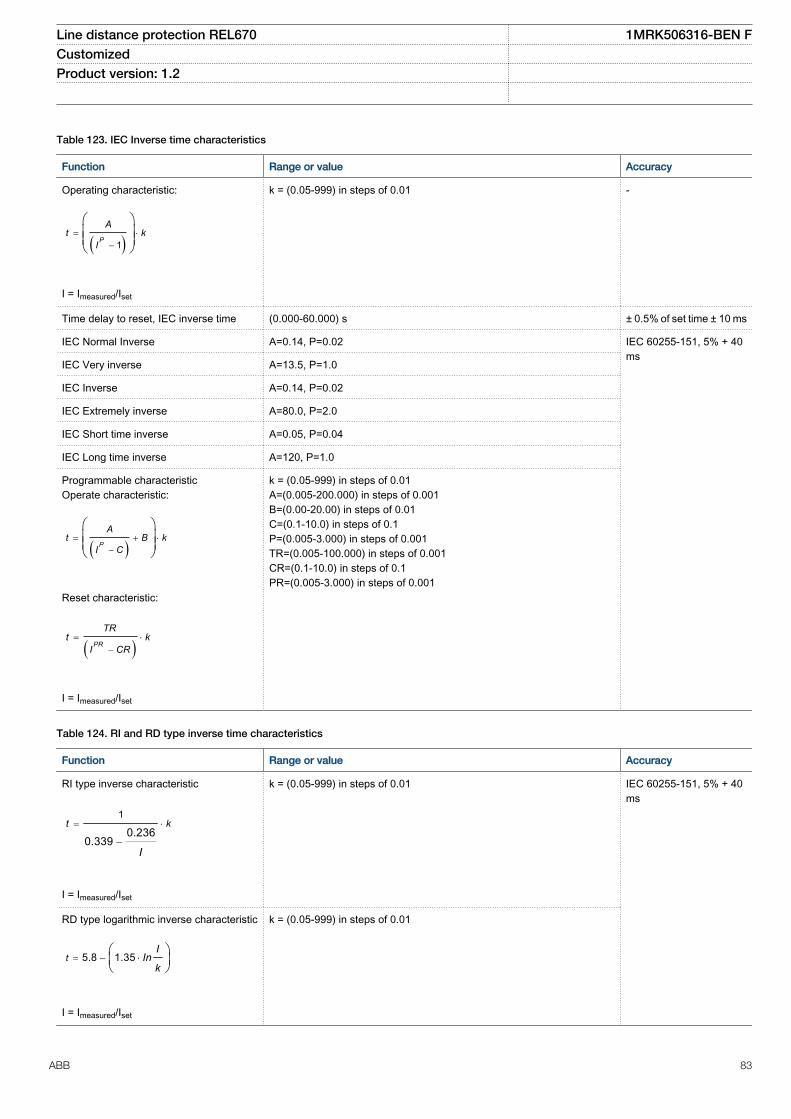
Table 123. IEC Inverse time characteristics
Function Range or value Accuracy
Operating characteristic:
( )1= ×
-
æ öç ÷ç ÷è ø
P
At k
I
EQUATION1251-SMALL V1 EN
I = Imeasured/Iset
k = (0.05-999) in steps of 0.01 -
Time delay to reset, IEC inverse time (0.000-60.000) s ± 0.5% of set time ± 10 ms
IEC Normal Inverse A=0.14, P=0.02 IEC 60255-151, 5% + 40ms
IEC Very inverse A=13.5, P=1.0
IEC Inverse A=0.14, P=0.02
IEC Extremely inverse A=80.0, P=2.0
IEC Short time inverse A=0.05, P=0.04
IEC Long time inverse A=120, P=1.0
Programmable characteristicOperate characteristic:
( )= + ×
-
æ öç ÷ç ÷è ø
P
At B k
I C
EQUATION1370-SMALL V1 EN
Reset characteristic:
( )= ×
-PR
TRt k
I CR
EQUATION1253-SMALL V1 EN
I = Imeasured/Iset
k = (0.05-999) in steps of 0.01A=(0.005-200.000) in steps of 0.001B=(0.00-20.00) in steps of 0.01C=(0.1-10.0) in steps of 0.1P=(0.005-3.000) in steps of 0.001TR=(0.005-100.000) in steps of 0.001CR=(0.1-10.0) in steps of 0.1PR=(0.005-3.000) in steps of 0.001
Table 124. RI and RD type inverse time characteristics
Function Range or value Accuracy
RI type inverse characteristic
1
0.2360.339
= ×
-
t k
IEQUATION1137-SMALL V1 EN
I = Imeasured/Iset
k = (0.05-999) in steps of 0.01 IEC 60255-151, 5% + 40ms
RD type logarithmic inverse characteristic
5.8 1.35= - ×æ öç ÷è ø
tI
Ink
EQUATION1138-SMALL V1 EN
I = Imeasured/Iset
k = (0.05-999) in steps of 0.01
Line distance protection REL670 1MRK506316-BEN FCustomized Product version: 1.2
ABB 83

Table 125. Inverse time characteristics for overvoltage protection
Function Range or value Accuracy
Type A curve:
=- >
>
æ öç ÷è ø
tk
U U
U
EQUATION1436-SMALL V1 EN
U> = Uset
U = Umeasured
k = (0.05-1.10) in steps of 0.01 5% +40 ms
Type B curve:
2.0
480
32 0.5 0.035
=×
- >× - -
>
æ öç ÷è ø
tk
U U
U
EQUATION1437-SMALL V1 EN
k = (0.05-1.10) in steps of 0.01
Type C curve:
3.0
480
32 0.5 0.035
=×
- >× - -
>
æ öç ÷è ø
tk
U U
U
EQUATION1438-SMALL V1 EN
k = (0.05-1.10) in steps of 0.01
Programmable curve:
×= +
- >× -
>
æ öç ÷è ø
P
k At D
U UB C
U
EQUATION1439-SMALL V1 EN
k = (0.05-1.10) in steps of 0.01A = (0.005-200.000) in steps of 0.001B = (0.50-100.00) in steps of 0.01C = (0.0-1.0) in steps of 0.1D = (0.000-60.000) in steps of 0.001P = (0.000-3.000) in steps of 0.001
Line distance protection REL670 1MRK506316-BEN FCustomized Product version: 1.2
84 ABB

Table 126. Inverse time characteristics for undervoltage protection
Function Range or value Accuracy
Type A curve:
=< -
<
æ öç ÷è ø
kt
U U
UEQUATION1431-SMALL V1 EN
U< = Uset
U = UVmeasured
k = (0.05-1.10) in steps of 0.01 5% +40 ms
Type B curve:
2.0
4800.055
32 0.5
×= +
< -× -
<
æ öç ÷è ø
kt
U U
U
EQUATION1432-SMALL V1 EN
U< = Uset
U = Umeasured
k = (0.05-1.10) in steps of 0.01
Programmable curve:
×= +
< -× -
<
é ùê úê úê úæ öê úç ÷ë è ø û
P
k At D
U UB C
U
EQUATION1433-SMALL V1 EN
U< = Uset
U = Umeasured
k = (0.05-1.10) in steps of 0.01A = (0.005-200.000) in steps of 0.001B = (0.50-100.00) in steps of 0.01C = (0.0-1.0) in steps of 0.1D = (0.000-60.000) in steps of 0.001P = (0.000-3.000) in steps of 0.001
Line distance protection REL670 1MRK506316-BEN FCustomized Product version: 1.2
ABB 85

Table 127. Inverse time characteristics for residual overvoltage protection
Function Range or value Accuracy
Type A curve:
=- >
>
æ öç ÷è ø
tk
U U
U
EQUATION1436-SMALL V1 EN
U> = Uset
U = Umeasured
k = (0.05-1.10) in steps of0.01
5% +40 ms
Type B curve:
2.0
480
32 0.5 0.035
=×
- >× - -
>
æ öç ÷è ø
tk
U U
U
EQUATION1437-SMALL V1 EN
k = (0.05-1.10) in steps of0.01
Type C curve:
3.0
480
32 0.5 0.035
=×
- >× - -
>
æ öç ÷è ø
tk
U U
U
EQUATION1438-SMALL V1 EN
k = (0.05-1.10) in steps of0.01
Programmable curve:
×= +
- >× -
>
æ öç ÷è ø
P
k At D
U UB C
U
EQUATION1439-SMALL V1 EN
k = (0.05-1.10) in steps of0.01A = (0.005-200.000) insteps of 0.001B = (0.50-100.00) in stepsof 0.01C = (0.0-1.0) in steps of 0.1D = (0.000-60.000) insteps of 0.001P = (0.000-3.000) in stepsof 0.001
Line distance protection REL670 1MRK506316-BEN FCustomized Product version: 1.2
86 ABB

22. Ordering
Guidelines
Carefully read and follow the set of rules to ensure problem-free order management. Be aware that certain functions can only be ordered incombination with other functions and that some functions require specific hardware selections.
Please refer to the available functions table for included application functions.
Product specification
Basic IED 670 platform and common functions housed in selected casing
REL670 Quantity: 1MRK 002 812-AD
Default:
The IED connect CD contains configuration alternative. Use the PCM600 to create or modify the configuration. The PCM600 can also be used foradaptation of an included example configuration.
Option:
Customer specific configuration On request
Connection type for Power supply modules and I/O modules
Rule: Same connection type for Power supply modules and I/O modules must be ordered
Compression terminals 1MRK 002 960-AA
Ring lug terminals 1MRK 002 960-BA
Power supply module
Rule: One Power supply module must be specified
Power supply module (PSM) 24-60 VDC 1MRK 002 239-AB
90-250 VDC 1MRK 002 239-BB
Line distance protection REL670 1MRK506316-BEN FCustomized Product version: 1.2
ABB 87

Impedance protection
Rule: One and only one of the alternatives (Alt. 1-4) can be ordered
Alternative 1: Rule: All functions within the alternative must be ordered.Note: Phase selection FDPSPDIS always included in this packageDistance protection zones, quadrilateral characteristic (ZMQPDIS, ZMQAPDIS)
Qty:
1 2 3 4 5
1MRK 002 904-XB
Directional impedance quadrilateral (ZDRDIR)
Qty:
1 2 1MRK 002 904-YB
Phase selection, quadrilateral characteristic with fixed angle (FDPSPDIS) Qty:
1 2 1MRK 002 904-AD
Alternative 2: Rule: All functions within the alternative must be orderedNote: Phase selection FDPSPDIS always included in this packageDistance measuring zone, quadrilateral characteristic for series compensated lines(ZMCPDIS, ZMCAPDIS)
Qty:
1 2 3 4 5
1MRK 002 925-AB
Directional impedance, including series compensation (ZDSRDIR) Qty:
1 2 1MRK 002 925-CB
Phase selection, quadrilateral characteristic with fixed angle (FDPSPDIS) Qty:
1 2 1MRK 002 904-AD
Alternative 3: Rule: All functions within the alternative must be orderedFull scheme distance protection, mho characteristic (ZMHPDIS)
Qty:
1 2 3 4 5
1MRK 002 925-EB
Full scheme distance protection, quadrilateral for earth faults (ZMMPDIS, ZMMAPDIS) Qty:
1 2 3 4 5 1MRK 002 925-GB
Directional impedance element for mho characteristic (ZDMRDIR, 21D) Qty:
1 2 1MRK 002 924-PA
Additional distance protection directional function for earth faults (ZDARDIR) Qty:
1 2 1MRK 002 908-VA
Mho impedance supervision logic (ZSMGAPC) Qty: 1MRK 002 908-UB
Faulty phase identification with load enchroachment (FMPSPDIS) Qty:
1 2 1MRK 002 925-BB
Alternative 4: Rule: All functions within the alternative must be orderedDistance protection zone. quadrilateral characteristic, separate settings (ZMRPDIS,ZMRAPDIS)
Qty:
1 2 3 4 5
1MRK 002 925-VA
Phase selection, quadrilateral characteristic with settable angle (FRPSPDIS) Qty:
1 2 1MRK 002 925-XA
Directional impedance quadrilateral (ZDRDIR)
Qty:
1 2 1MRK 002 904-YB
Line distance protection REL670 1MRK506316-BEN FCustomized Product version: 1.2
88 ABB

Logic
Rule: One Tripping logic must be ordered
Tripping logic (SMPPTRC) Qty:
1 2 1MRK 002 917-AC
Optional functionsDifferential protection
1Ph High impedance differential protection (HZPDIF)
Qty:
1 2 3 1MRK 002 901-HB
Impedance protection
Note: Optional with alternative 1Directional impedance element for mho characteristic (ZDMRDIR)
Qty:
1 2
1MRK 002 924-PA
Note: Optional with alternative 1, 2 and 4Faulty phase identification with load encroachment (FMPSPDIS)
Qty:
1 2
1MRK 002 925-BB
Note: Optional with alternative 3Phase selection, quadrilateral characteristic with fixed angle (FDPSPDIS)
Qty:
1 2
1MRK 002 904-AD
Power swing detection (ZMRPSB) Qty: 1MRK 002 904-NB
Power swing logic (ZMRPSL) Qty: 1MRK 002 924-RB
Pole slip/out-of-step protection (PSPPPAM)
Qty:
1 2 1MRK 002 925-LB
Phase preference logic (PPLPHIZ) Qty: 1MRK 002 908-LB
Line distance protection REL670 1MRK506316-BEN FCustomized Product version: 1.2
ABB 89

Current protection
Instantaneous phase overcurrent protection (PHPIOC)
Qty:
1 2 3 1MRK 002 906-AC
Four step phase overcurrent protection (OC4PTOC) Qty: 1MRK 002 906-BD
Instantaneous residual overcurrent protection (EFPIOC)
Qty:
1 2 3 1MRK 002 906-CC
Four step residual overcurrent protection (EF4PTOC)
Qty:
1 2 3 1MRK 002 906-DD
Four step directional negative phase sequence overcurrent protection (NS4PTOC)
Qty:
1 2 1MRK 002 906-DM
Sensitive directional residual overcurrent and power protection (SDEPSDE) Qty: 1MRK 002 907-DC
Thermal overload protection, one time constant (LPTTR)
Qty:
1 2 1MRK 002 906-LD
Breaker failure protection (CCRBRF)
Qty:
1 2 1MRK 002 906-RC
Stub protection (STBPTOC) Qty: 1MRK 002 906-ZC
Pole discordance protection (CCRPLD)
Qty:
1 2 1MRK 002 907-AC
Directional underpower protection (GUPPDUP)
Qty:
1 2 1MRK 002 902-FB
Directional overpower protection (GOPPDUP)
Qty:
1 2 1MRK 002 902-GB
Voltage protection
Two step undervoltage protection (UV2PTUV)
Qty:
1 2 1MRK 002 908-AC
Two step overvoltage protection (OV2PTOV)
Qty:
1 2 1MRK 002 908-DC
Two step residual overvoltage protection (ROV2PTOV)
Qty:
1 2 1MRK 002 908-GC
Overexcitation protection (OEXPVPH) Qty: 1MRK 002 908-MC
Voltage differential protection (VDCPTOV)
Qty:
1 2 1MRK 002 924-TB
Frequency protection
Underfrequency protection (SAPTUF)
Qty:
1 2 1MRK 002 908-NC
Overfrequency protection (SAPTOF)
Qty:
1 2 1MRK 002 908-RC
Rate-of-change frequency protection (SAPFRC)
Qty:
1 2 1MRK 002 908-SB
Line distance protection REL670 1MRK506316-BEN FCustomized Product version: 1.2
90 ABB

Multipurpose protection
General current and voltage protection (CVGAPC)
Qty:
1 2 3 4 1MRK 002 902-AB
Secondary system supervision
Current circuit supervision (CCSRDIF)
Qty:
1 2 1MRK 002 914-AB
Fuse failure supervision (SDDRFUF)
Qty:
1 2 3 1MRK 002 914-GC
Control
Synchrocheck, energizing check and synchronizing (SESRSYN)
Qty:
1 2 1MRK 002 916-AD
Autorecloser (SMBRREC)
Qty:
1 2 3 4 1MRK 002 916-EB
Rule: Only one of Apparatus control can be ordered
Apparatus control for single bay, max 8 apparatuses (1CB) incl. interlocking 1MRK 002 916-GD
Apparatus control for single bay, max 15 apparatuses (2CBs) incl. interlocking 1MRK 002 916-HD
Scheme communication
Rule: Only one of (ZCPSCH/ZC1PPSCH) can be ordered
Scheme communication logic for distance protection or overcurrent protection (ZCPSCH) 1MRK 002 904-RA
Phase segregated Scheme communication logic for distance protection (ZC1PPSCH) 1MRK 002 924-VA
Rule: Only one of (ZCRWPSCH/ZC1WPSCH) can be ordered
Current reversal and weak end infeed logic for distance protection (ZCRWPSCH) 1MRK 002 904-SB
Current reversal and weak end infeed logic for phase segregated communication (ZC1WPSCH) 1MRK 002 925-DB
Scheme communication logic for residual overcurrent protection (ECPSCH) 1MRK 002 906-GA
Current reversal and weak end infeed logic for residual overcurrent protection (ECRWPSCH) 1MRK 002 906-HB
Direct transfer trip
Direct transfer trip (DTT) Qty: 1MRK 002 927-XA
Station communication
Note: Require 2-channel OEM
IEC 62439-3 Edition 1 parallel redundancy protocol 1MRK 002 924-YR
IEC 62439-3 Edition 2 parallel redundancy protocol 1MRK 002 924-YS
Line distance protection REL670 1MRK506316-BEN FCustomized Product version: 1.2
ABB 91

First local HMI user dialogue language
Rule: One must be ordered
HMI language, English IEC 1MRK 002 930-AA
HMI language, English US 1MRK 002 930-BA
Additional local HMI user dialogue language
Rule: Maximum one alternative
HMI language, German 1MRK 002 920-AB
HMI language, Russian 1MRK 002 920-BB
HMI language, French 1MRK 002 920-DB
HMI language, Spanish 1MRK 002 920-DB
HMI language, Polish 1MRK 002 920-GB
HMI language, Hungarian 1MRK 002 920-FB
HMI language, Czech 1MRK 002 920-HB
HMI language, Swedish 1MRK 002 920-KB
Optional hardwareHuman machine hardware interface
Rule: One must be ordered.
Display type Keypad symbol Case size
Small, alpha numeric IEC 1/2 19" 1MRK 000 008-HB
Small, alpha numeric IEC 3/4 19" 1MRK 000 008-PB
Small, alpha numeric IEC 1/1 19" 1MRK 000 008-KB
Medium, graphic display IEC 1/2 19" 1MRK 000 008-LB
Medium, graphic display IEC 1/1 19" 1MRK 000 008-MB
Medium, graphic display IEC 3/4 19" 1MRK 000 008-NB
Medium, graphic display ANSI 1/2 19" 1MRK 000 008-LC
Medium, graphic display ANSI 3/4 19" 1MRK 000 008-NC
Medium, graphic display ANSI 1/1 19" 1MRK 000 008-MC
Line distance protection REL670 1MRK506316-BEN FCustomized Product version: 1.2
92 ABB

Analog system
Rule: One Transformer input module must be orderedNote: The same type of connection terminals has to be ordered for both TRMs
Transformer input module, compression terminals 9I+3U, 1A, 50/60 Hz
Qty:
1 2 1MRK 002 247-BG
Transformer input module, compression terminals 9I+3U, 5A, 50/60 Hz
Qty:
1 2 1MRK 002 247-BH
Transformer input module, compression terminals 5I, 1A+4I, 5A+3U,50/60 Hz
Qty:
1 2 1MRK 002 247-BK
Transformer input module, compression terminals 7I+5U, 1A, 50/60 Hz
Qty:
1 2 1MRK 002 247-AP
Transformer input module, compression terminals 7I+5U, 5A, 50/60 Hz
Qty:
1 2 1MRK 002 247-AR
Transformer input module, compression terminals 6I, 5A+1I, 1A+5U,50/60 Hz
Qty:
1 2 1MRK 002 247-AU
Transformer input module, compression terminals 3I, 5A+4I, 1A+5U,50/60 Hz
Qty:
1 2 1MRK 002 247-AV
Transformer input module, compression terminals 3IM, 1A+4IP, 1A+5U,50/60 Hz
Qty: 1 2 1MRK 002 247-EA
Transformer input module, compression terminals 3IM, 5A+4IP, 5A+5U,50/60 Hz
Qty: 1 2 1MRK 002 247-EB
Transformer input module, compression terminals 6I+6U, 1A, 50/60 Hz
Qty:
1 2 1MRK 002 247-AG
Transformer input module, compression terminals 6I+6U, 5A, 50/60 Hz
Qty:
1 2 1MRK 002 247-AH
Transformer input module, compression terminals 3I, 5A+3I, 1A+6U,50/60 Hz
Qty:
1 2 1MRK 002 247-AE
Transformer input module, compression terminals (Only as second TRM) 6I, 1A, 50/60 Hz Qty 1 1MRK 002 247-DG
Transformer input module, compression terminals (Only as second TRM) 6I, 5A, 50/60 Hz Qty: 1 1MRK 002 247-DH
Transformer input module, ring lug terminals 9I+3U, 1A, 50/60 Hz
Qty:
1 2 1MRK 002 247-BC
Transformer input module, ring lug terminals 9I+3U, 5A, 50/60 Hz Qty:
1 2 1MRK 002 247-BD
Transformer input module, ring lug terminals 5I, 1A+4I, 5A+3U,50/60 Hz
Qty:
1 2 1MRK 002 247-BF
Line distance protection REL670 1MRK506316-BEN FCustomized Product version: 1.2
ABB 93

Transformer input module, ring lug terminals 7I+5U, 1A, 50/60 Hz
Qty: 1 2 1MRK 002 247-AS
Transformer input module, ring lug terminals 7I+5U, 5A, 50/60 Hz Qty:
1 2 1MRK 002 247-AT
Transformer input module, ring lug terminals 6I, 5A+1I, 1A+5U,50/60 Hz
Qty:
1 2 1MRK 002 247-AX
Transformer input module, ring lug terminals 3I, 5A+4I, 1A+5U,50/60 Hz
Qty:
1 2 1MRK 002 247-AY
Transformer input module, ring lug terminals 3IM, 1A+4IP, 1A+5U,50/60 Hz
Qty: 1 2 1MRK 002 247-EC
Transformer input module, ring lug terminals 3IM, 5A+4IP, 5A+5U,50/60 Hz
Qty: 1 2 1MRK 002 247-ED
Transformer input module, ring lug terminals 6I+6U, 1A, 50/60 Hz
Qty:
1 2 1MRK 002 247-AC
Transformer input module, ring lug terminals 6I+6U, 5A, 50/60 Hz
Qty:
1 2 1MRK 002 247-AD
Transformer input module, ring lug terminals 3I, 5A+3I, 1A+6U,50/60 Hz
Qty:
1 2 1MRK 002 247-AF
Transformer input module, ring lug terminals (Only as second TRM) 6I, 1A, 50/60 Hz
Qty:
1 1MRK 002 247-DC
Transformer input module, ring lug terminals (Only as second TRM) 6I, 5A, 50/60 Hz
Qty:
1 1MRK 002 247-DD
Note: One Analog digital conversion module, with time synchronization is always delivered with each Transformer input module.
Case size
When ordering I/O modules, observe the maximum quantities according to tables below.
Note: Standard order of location for I/O modules is BIM-BOM-SOM-IOM-MIM from left to right as seen from the rear side of the IED, but can alsobe freely placed.
Note: Maximum quantity of I/O modules depends on the type of connection terminals.
Maximum quantity of I/O modules
Case sizes BIM IOM BOM/SOM
MIM Maximum in case
1/1 x 19”, one (1) TRM 14 6 4 4 14 (max 4 BOM+SOM+MIM)
1MRK 000 151-NC
1/1 x 19”, two (2) TRM 11 6 4 4 11 (max 4 BOM+SOM+MIM)
1MRK 000 151-ND
3/4 x 19”, one (1) TRM 8 6 4 1 8 (max 4 BOM+SOM+1MIM)
1MRK 000 151-NB
3/4 x 19”, two (2) TRM 5 5 4 1 5 (max 4 BOM+SOM+1MIM)
1MRK 000 151-NE
1/2 x 19”, one (1) TRM 3 3 3 0 3 1MRK 000 151-NA
Line distance protection REL670 1MRK506316-BEN FCustomized Product version: 1.2
94 ABB

Maximum quantity of I/O modules, with ring lug terminals, module limits see above
Case sizes Maximum in case Possible locations for I/O moduleswith ringlugs
1/1 x 19”, one (1) TRM 7 P3, P5, P7, P9, P11, P13, P15 1MRK 000 151-NC
1/1 x 19”, two (2) TRM 5 P3, P5, P7, P9, P11 1MRK 000 151-ND
3/4 x 19”, one (1) TRM 4 P3, P5, P7, P9 1MRK 000 151-NB
3/4 x 19”, two (2) TRM 2 P3, P5 1MRK 000 151-NE
1/2 x 19”, one (1) TRM 1 P3 1MRK 000 151-NA
Line distance protection REL670 1MRK506316-BEN FCustomized Product version: 1.2
ABB 95

Binary input/output modules
Make BIM with 50 mA inrush current the primary choice. BIM with 50 mA inrush current fulfill additional standards. As a consequence the EMCwithstand capability is further increased.For pulse counting, for example kWh metering, the BIM with enhanced pulse counting capabilities must be used.
Binary input module (BIM) 16 inputs
RL 24-30 VDC, 30 mA Qty: 1 2 3 4 5 6
8 9 10 11 12 13
7
14
1MRK 000 508-DB
RL 48-60 VDC, 30 mA Qty: 1 2 3 4 5 6
8 9 10 11 12 13
7
14
1MRK 000 508-AB
RL 110-125 VDC, 30 mA Qty: 1 2 3 4 5 6
8 9 10 11 12 13
7
14
1MRK 000 508-BB
RL 220-250 VDC, 30 mA Qty: 1 2 3 4 5 6
8 9 10 11 12 13
7
14
1MRK 000 508-CB
RL 24-30 VDC, 50 mA Qty: 1 2 3 4 5 6
8 9 10 11 12 13
7
14
1MRK 000 508-DD
RL 48-60 VDC, 50 mA Qty: 1 2 3 4 5 6
8 9 10 11 12 13
7
14
1MRK 000 508-AD
RL 110-125 VDC, 50 mA Qty: 1 2 3 4 5 6
8 9 10 11 12 13
7
14
1MRK 000 508-BD
RL 220-250 VDC, 50 mA Qty: 1 2 3 4 5 6
8 9 10 11 12 13
7
14
1MRK 000 508-CD
Binary input module (BIM) with enhanced pulse counting capabilities, 16 inputs
Line distance protection REL670 1MRK506316-BEN FCustomized Product version: 1.2
96 ABB

RL 24-30 VDC Qty: 1 2 3 4 5 6
8 9 10 11 12 13
7
14
1MRK 000 508-HA
RL 48-60 VDC Qty: 1 2 3 4 5 6
8 9 10 11 12 13
7
14
1MRK 000 508-EA
RL 110-125 VDC Qty: 1 2 3 4 5 6
8 9 10 11 12 13
7
14
1MRK 000 508-FA
RL 220-250 VDC Qty: 1 2 3 4 5 6
8 9 10 11 12 13
7
14
1MRK 000 508-GA
Binary output module 24 output relays (BOM) Qty: 1 2 3 4 5 6
8 9 10 11 12 13
7
14
1MRK 000 614-AB
Static binary output module (SOM)
RL 48-60 VDC Qty: 1 2 3 4 5 6
8 9 10 11 12 13
7
14
1MRK 002 614-BA
RL 110-250 VDC Qty: 1 2 3 4 5 6
8 9 10 11 12 13
7
14
1MRK 002 614-CA
Line distance protection REL670 1MRK506316-BEN FCustomized Product version: 1.2
ABB 97

Make IOM with 50 mA inrush current the primary choice. IOM with 50 mA inrush current fulfill additional standards. As aconsequence the EMC withstand capability is further increased.IOM with 30 mA inrush current is still available.
Binary input/output module (IOM) 8 inputs, 10 outputs, 2 high-speed outputs
RL 24-30 VDC, 30 mA Qty: 1 2 3 4 5 6 1MRK 000 173-GB
RL 48-60 VDC, 30 mA Qty: 1 2 3 4 5 6 1MRK 000 173-AC
RL 110-125 VDC, 30 mA Qty: 1 2 3 4 5 6 1MRK 000 173-BC
RL 220-250 VDC, 30 mA Qty: 1 2 3 4 5 6 1MRK 000 173-CC
RL 24-30 VDC, 50 mA Qty: 1 2 3 4 5 6 1MRK 000 173-GD
RL 48-60 VDC, 50 mA Qty: 1 2 3 4 5 6 1MRK 000 173-AE
RL 110-125 VDC, 50 mA Qty: 1 2 3 4 5 6 1MRK 000 173-BE
RL 220-250 VDC, 50 mA Qty: 1 2 3 4 5 6 1MRK 000 173-CE
Binary input/output module (IOM with MOV), 8 inputs, 10 outputs, 2 high-speed outputs
RL 24-30 VDC Qty: 1 2 3 4 5 6 1MRK 000 173-GC
RL 48-60 VDC Qty: 1 2 3 4 5 6 1MRK 000 173-AD
RL 110-125 VDC Qty: 1 2 3 4 5 6 1MRK 000 173-BD
RL 220-250 VDC Qty: 1 2 3 4 5 6 1MRK 000 173-CD
mA input module 6 channels (MIM) Qty: 1 2 3 4 1MRK 000 284-AB
Line distance protection REL670 1MRK506316-BEN FCustomized Product version: 1.2
98 ABB

Station communication ports
Note: Optical ethernet module, 2 glass interfaces is not allowed together with SLM.
Optical ethernet module, 1 channel glass 1MRK 002 266-AA
Optical ethernet module, 2 channel glass 1MRK 002 266-BA
Serial and LON communication module, supports SPA/IEC 60870-5-103, LON and DNP 3.0
Serial/LON plastic interface 1MRK 001 608-AB
Serial plastic/LON glass interface 1MRK 001 608-BB
Serial/LON glass interface 1MRK 001 608-CB
Galvanic RS485 communication module for DNP 3.0 1MRK 002 309-AA
Remote end serial communication for C37.94
Rule: Max two LDCM can be ordered
Optical short range line data communication module(Multi mode 850 nm) (SR LDCM)
Qty:
1 2 1MRK 002 122-AB
Optical medium range line data communication module(Single mode 1310 nm) (MR LDCM)
Qty:
1 2 1MRK 002 311-AA
Optical long range line data communication module(Single mode 1550 nm) (LR LDCM)
Qty:
1 2 1MRK 002 311-BA
Galvanic X21 line data communication module (X21 LDCM)
Qty:
1 2 1MRK 002 307-AA
Time synchronization
Rule: Only one Time synchronization can be ordered.
GPS Time module (GTM) 1MRK 002 282-AB
IRIG-B Time synchronization module 1MRK 002 305-AA
Engineering facilities
19” rack mounting kit for 1/2 x 19” case or 2 x RHGS6 or RHGS12 Quantity: 1MRK 002 420-BB
19” rack mounting kit for 3/4 x 19” case or 3 x RHGS6 Quantity: 1MRK 002 420-BA
19” rack mounting kit for 1/1 x 19” case Quantity: 1MRK 002 420-CA
Note: Wall mounting not recommended with communication modules with fibre connection (SLM,OEM, LDCM)Wall mounting kit for terminal
Quantity: 1MRK 002 420-DA
Flush mounting kit for terminal Quantity: 1MRK 000 020-Y
Flush mounting kit + IP54 sealing (factory mounted). Cannot be ordered separately thus must bespecified when ordering a terminal.
Quantity: 1MRK 002 420-EA
Line distance protection REL670 1MRK506316-BEN FCustomized Product version: 1.2
ABB 99

AccessoriesGPS antenna and mounting details
GPS antenna, including mounting kits Quantity: 1MRK 001 640-AA
Cable for antenna, 20 m Quantity: 1MRK 001 665-AA
Cable for antenna, 40 m Quantity: 1MRK 001 665-BA
Interface converter (for remote end data communication)
External interface converter from C37.94 to G703 Quantity: 1 2 1MRK 002 245-AA
External interface converter from C37.94 to G703.E1 Quantity: 1 2 1MRK 002 245-BA
Test switchThe test system COMBITEST intended for use with the IED670 products is described in 1MRK 512 001-BEN and 1MRK001024-CA. Please refer to the website:www.abb.com/substationautomation for detailed information.
Due to the high flexibility of our product and the wide varietyof applications possible the test switches needs to beselected for each specific application.
Select your suitable test switch base on the availablecontacts arrangements shown in the referencedocumentation.
However our proposals for suitable variants are;
Single breaker/Single or Three Phase trip with internal neutralon current circuits (ordering number RK926 315-AK).
Single breaker/Single or Three Phase trip with external neutralon current circuits (ordering number RK926 315-AC).
Multi-breaker/Single or Three Phase trip with internal neutralon current circuits (ordering number RK926 315-BE).
Multi-breaker/Single or Three Phase trip with external neutralon current circuit (ordering number RK926 315-BV).
The normally open "In test mode" contact 29-30 on the RTXPtest switches should be connected to the input of the testfunction block to allow activation of functions individuallyduring testing.
Test switches type RTXP 24 is ordered separately. Pleaserefer to Section "Related documents" for reference tocorresponding documents.
RHGS 6 Case or RHGS 12 Case with mounted RTXP 24 andthe on/off switch for dc-supply are ordered separately. Pleaserefer to Section "Related documents" for reference tocorresponding documents.
Protection cover
Protective cover for rear side of RHGS6, 6U, 1/4 x 19” Quantity: 1MRK 002 420-AE
Protective cover for rear side of terminal, 6U, 1/2 x 19” Quantity: 1MRK 002 420-AC
Protective cover for rear side of terminal, 6U, 3/4 x 19” Quantity: 1MRK 002 420-AB
Protective cover for rear side of terminal, 6U, 1/1 x 19” Quantity: 1MRK 002 420-AA
Line distance protection REL670 1MRK506316-BEN FCustomized Product version: 1.2
100 ABB
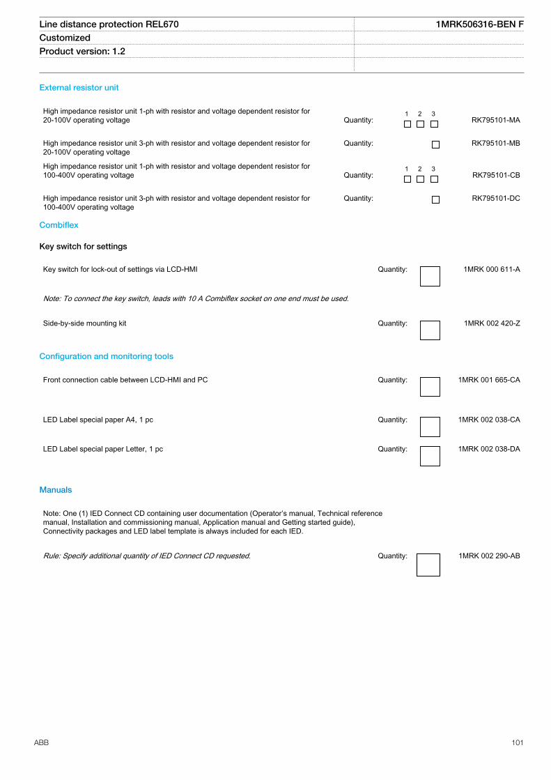
External resistor unit
High impedance resistor unit 1-ph with resistor and voltage dependent resistor for20-100V operating voltage
Quantity:
1 2 3 RK795101-MA
High impedance resistor unit 3-ph with resistor and voltage dependent resistor for20-100V operating voltage
Quantity: RK795101-MB
High impedance resistor unit 1-ph with resistor and voltage dependent resistor for100-400V operating voltage
Quantity:
1 2 3 RK795101-CB
High impedance resistor unit 3-ph with resistor and voltage dependent resistor for100-400V operating voltage
Quantity: RK795101-DC
Combiflex
Key switch for settings
Key switch for lock-out of settings via LCD-HMI Quantity: 1MRK 000 611-A
Note: To connect the key switch, leads with 10 A Combiflex socket on one end must be used.
Side-by-side mounting kit Quantity: 1MRK 002 420-Z
Configuration and monitoring tools
Front connection cable between LCD-HMI and PC Quantity: 1MRK 001 665-CA
LED Label special paper A4, 1 pc Quantity: 1MRK 002 038-CA
LED Label special paper Letter, 1 pc Quantity: 1MRK 002 038-DA
Manuals
Note: One (1) IED Connect CD containing user documentation (Operator’s manual, Technical referencemanual, Installation and commissioning manual, Application manual and Getting started guide),Connectivity packages and LED label template is always included for each IED.
Rule: Specify additional quantity of IED Connect CD requested. Quantity: 1MRK 002 290-AB
Line distance protection REL670 1MRK506316-BEN FCustomized Product version: 1.2
ABB 101

User documentation
Rule: Specify the number of printed manuals requested
Operator’s manual IEC Quantity: 1MRK 506 313-UEN
ANSI Quantity: 1MRK 506 313-UUS
Technical reference manual IEC Quantity: 1MRK 506 312-UEN
ANSI Quantity: 1MRK 506 312-UUS
Installation and commissioning manual IEC Quantity: 1MRK 506 314-UEN
ANSI Quantity: 1MRK 506 314-UUS
Application manual IEC Quantity: 1MRK 506 315-UEN
ANSI Quantity: 1MRK 506 315-UUS
Engineering manual, 670 series Quantity: 1MRK 511 240-UEN
Reference information
For our reference and statistics we would be pleased to be provided with the following application data:
Country: End user:
Station name: Voltage level: kV
Related documents
Documents related to REL670 Identity number
Operator’s manual 1MRK 506 313-UEN
Installation and commissioning manual 1MRK 506 314-UEN
Technical reference manual 1MRK 506 312-UEN
Application manual 1MRK 506 315-UEN
Product guide customized 1MRK 506 316-BEN
Product guide pre-configured 1MRK 506 317-BEN
Product guide IEC 61850-9-2 1MRK 506 299-BEN
Sample specification SA2005-001282
Line distance protection REL670 1MRK506316-BEN FCustomized Product version: 1.2
102 ABB

Connection and Installation components 1MRK 513 003-BEN
Test system, COMBITEST 1MRK 512 001-BEN
Accessories for 670 series IEDs 1MRK 514 012-BEN
670 series SPA and signal list 1MRK 500 092-WEN
IEC 61850 Data objects list for 670 series 1MRK 500 091-WEN
Engineering manual 670 series 1MRK 511 240-UEN
Communication set-up for Relion 670 series 1MRK 505 260-UEN
More information can be found on www.abb.com/substationautomation.
Line distance protection REL670 1MRK506316-BEN FCustomized Product version: 1.2
ABB 103

104

Contact us
ABB ABSubstation Automation ProductsSE-721 59 Västerås, SwedenPhone +46 (0) 21 32 50 00Fax +46 (0) 21 14 69 18
www.abb.com/substationautomation
1MR
K50
6316
-BE
N F
© C
opyr
ight
201
2 A
BB
. All
right
s re
serv
ed.