Embed Size (px)
Citation preview
Linac Technical ReviewLinac Technical Review Patrick Krejcik, LCLSPatrick Krejcik, LCLSDecember 12, 2003December 12, 2003 [email protected]@slac.stanford.edu
LCLSLCLSLinac Coherent Light Source Stanford Synchrotron Radiation Laboratory
Stanford Linear Accelerator Center
LCLSLCLS
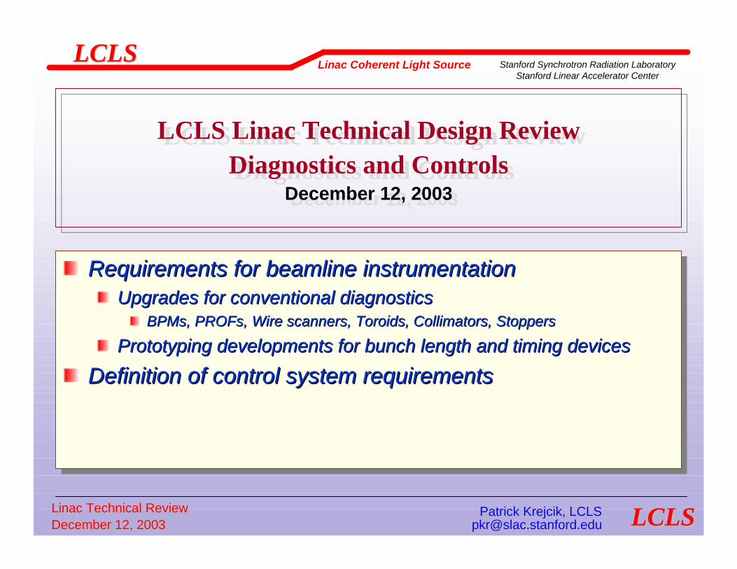
LCLS Linac Technical Design ReviewDiagnostics and Controls
December 12, 2003
LCLS Linac Technical Design ReviewDiagnostics and Controls
December 12, 2003
Requirements for beamline instrumentationUpgrades for conventional diagnostics
BPMs, PROFs, Wire scanners, Toroids, Collimators, Stoppers
Prototyping developments for bunch length and timing devices
Definition of control system requirements
Requirements for beamline instrumentationRequirements for beamline instrumentationUpgrades for conventional diagnosticsUpgrades for conventional diagnostics
BPMsBPMs, , PROFsPROFs, Wire scanners, , Wire scanners, ToroidsToroids, Collimators, Stoppers, Collimators, Stoppers
Prototyping developments for bunch length and timing devicesPrototyping developments for bunch length and timing devices
Definition of control system requirementsDefinition of control system requirements

Linac Technical ReviewLinac Technical Review Patrick Krejcik, LCLSPatrick Krejcik, LCLSDecember 12, 2003December 12, 2003 [email protected]@slac.stanford.edu
LCLSLCLSLinac Coherent Light Source Stanford Synchrotron Radiation Laboratory
Stanford Linear Accelerator Center
LCLSLCLS
Beamline instrumentation
Conventional diagnostics and their upgradesBPMs, Toroids, Wire scanners, Prof Monitors, Synchrotron Radiation, Beam Phase, Collimation, Loss monitors
Bunch length and timing diagnosticsFast, single-bunch relative length measurement for tuning
Linac energy wakeloss scanTHz spectral power
OTRCSR
Absolute bunch length determinationAverage bunch length from CTR autocorrelation3-bunch measurement with transverse RF deflecting cavitySingle shot electro optic pump probe measurement
Conventional diagnostics and their upgradesConventional diagnostics and their upgradesBPMsBPMs, , ToroidsToroids, Wire scanners, Prof Monitors, Synchrotron , Wire scanners, Prof Monitors, Synchrotron Radiation, Beam Phase, Collimation, Loss monitorsRadiation, Beam Phase, Collimation, Loss monitors
Bunch length and timing diagnosticsBunch length and timing diagnosticsFast, singleFast, single--bunch relative length measurement for tuningbunch relative length measurement for tuning
Linac energy Linac energy wakelosswakeloss scanscanTHz spectral powerTHz spectral power
OTROTRCSRCSR
Absolute bunch length determinationAbsolute bunch length determinationAverage bunch length from CTR autocorrelationAverage bunch length from CTR autocorrelation33--bunch measurement with transverse RF deflecting cavitybunch measurement with transverse RF deflecting cavitySingle shot electro optic pump probe measurementSingle shot electro optic pump probe measurement

Linac Technical ReviewLinac Technical Review Patrick Krejcik, LCLSPatrick Krejcik, LCLSDecember 12, 2003December 12, 2003 [email protected]@slac.stanford.edu
LCLSLCLSLinac Coherent Light Source Stanford Synchrotron Radiation Laboratory
Stanford Linear Accelerator Center
LCLSLCLS
Controls
Modes of beam operationControl system architecture requirements
Single pulse reading and id in a shared SLC/Epics system
Timing requirementsLow level RF controlFeedback requirements. Pulse-to-pulse control of
Orbit position & angle, energy, beam phase, bunch length
MPSStoppers and beam dumpers
PPSControl room
Modes of beam operationModes of beam operationControl system architecture requirementsControl system architecture requirements
Single pulse reading and id in a shared SLC/Epics systemSingle pulse reading and id in a shared SLC/Epics system
Timing requirementsTiming requirementsLow level RF controlLow level RF controlFeedback requirements. PulseFeedback requirements. Pulse--toto--pulse control ofpulse control of
Orbit position & angle, energy, beam phase, bunch lengthOrbit position & angle, energy, beam phase, bunch length
MPSMPSStoppers and beam dumpersStoppers and beam dumpers
PPSPPSControl roomControl room
Linac Technical ReviewLinac Technical Review Patrick Krejcik, LCLSPatrick Krejcik, LCLSDecember 12, 2003December 12, 2003 [email protected]@slac.stanford.edu
LCLSLCLSLinac Coherent Light Source Stanford Synchrotron Radiation Laboratory
Stanford Linear Accelerator Center
LCLSLCLS
Conventional diagnostics and their upgradesConventional diagnostics and their upgrades
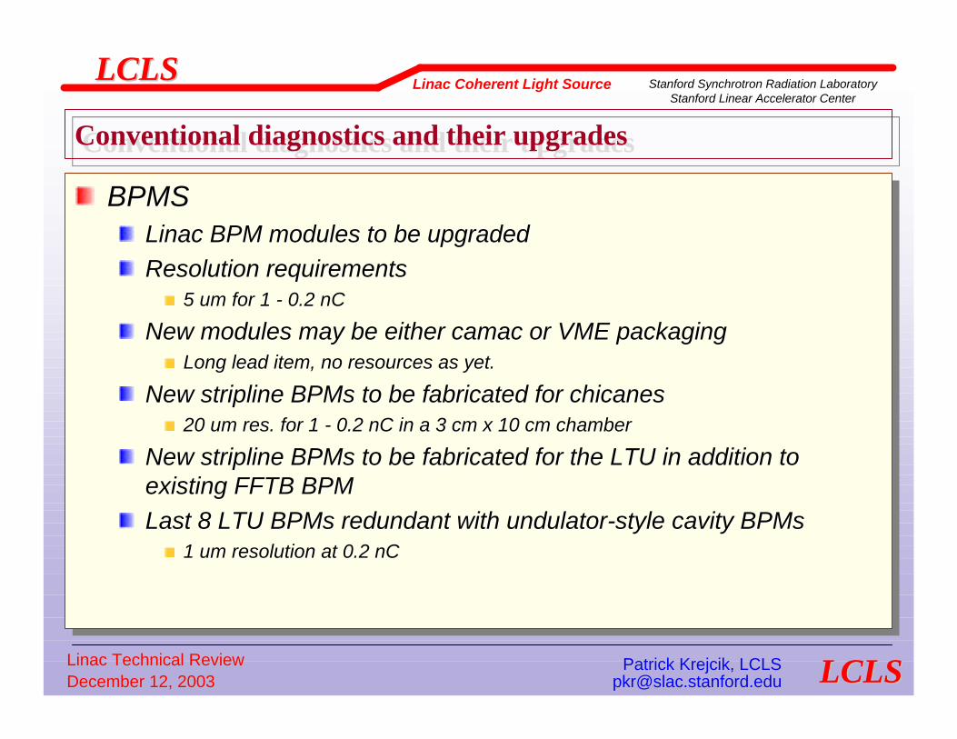
BPMSLinac BPM modules to be upgradedResolution requirements
5 um for 1 - 0.2 nC
New modules may be either camac or VME packagingLong lead item, no resources as yet.
New stripline BPMs to be fabricated for chicanes20 um res. for 1 - 0.2 nC in a 3 cm x 10 cm chamber
New stripline BPMs to be fabricated for the LTU in addition to existing FFTB BPMLast 8 LTU BPMs redundant with undulator-style cavity BPMs
1 um resolution at 0.2 nC
BPMSBPMSLinac BPM modules to be upgradedLinac BPM modules to be upgradedResolution requirementsResolution requirements
5 um for 1 5 um for 1 -- 0.2 0.2 nCnC
New modules may be either New modules may be either camaccamac or VME packagingor VME packagingLong lead item, no resources as yet.Long lead item, no resources as yet.
New New striplinestripline BPMsBPMs to be fabricated for chicanesto be fabricated for chicanes20 um res. for 1 20 um res. for 1 -- 0.2 0.2 nCnC in a 3 cm x 10 cm chamberin a 3 cm x 10 cm chamber
New New striplinestripline BPMsBPMs to be fabricated for the LTU in addition to to be fabricated for the LTU in addition to existing FFTB BPMexisting FFTB BPMLast 8 LTU Last 8 LTU BPMsBPMs redundant with undulatorredundant with undulator--style cavity style cavity BPMsBPMs
1 um resolution at 0.2 1 um resolution at 0.2 nCnC

Linac Technical ReviewLinac Technical Review Patrick Krejcik, LCLSPatrick Krejcik, LCLSDecember 12, 2003December 12, 2003 [email protected]@slac.stanford.edu
LCLSLCLSLinac Coherent Light Source Stanford Synchrotron Radiation Laboratory
Stanford Linear Accelerator Center
LCLSLCLS
Wire scanners – average, projected emittanceLattice locations optimized for phase advanceSmall wire diameters for low emittance beamsCompromise between high Z for signal and low Z carbon wires in the LTU to minimize beam loss in the undulator
Prof Monitors – single shot beam size, energy spreadHigh resolution measurement of small spots to be achieved with OTR screens (disruptive)
But requires careful, remote optics engineering layout and digital video acquisitionOTR screens require optical alignment – gaining experience at SPPSCan distinguish OTR from sync rad. in chicane bends with polarizers
Wire scanners Wire scanners –– average, projected emittanceaverage, projected emittanceLattice locations optimized for phase advanceLattice locations optimized for phase advanceSmall wire diameters for low emittance beamsSmall wire diameters for low emittance beamsCompromise between high Z for signal and low Z carbon wires in tCompromise between high Z for signal and low Z carbon wires in the LTU to he LTU to minimize beam loss in the undulatorminimize beam loss in the undulator
Prof Monitors Prof Monitors –– single shot beam size, energy spreadsingle shot beam size, energy spreadHigh resolution measurement of small spots to be achieved with OHigh resolution measurement of small spots to be achieved with OTR TR screens (screens (disruptivedisruptive))
But requires careful, remote optics engineering layout and digitBut requires careful, remote optics engineering layout and digital video acquisitional video acquisitionOTR screens require optical alignment OTR screens require optical alignment –– gaining experience at SPPSgaining experience at SPPSCan distinguish OTR from sync Can distinguish OTR from sync radrad. in chicane bends with . in chicane bends with polarizerspolarizers
Conventional diagnostics and their upgradesConventional diagnostics and their upgrades
SPPS BC chicane measured energy spreadSPPS BC chicane measured energy spread
SR background

Linac Technical ReviewLinac Technical Review Patrick Krejcik, LCLSPatrick Krejcik, LCLSDecember 12, 2003December 12, 2003 [email protected]@slac.stanford.edu
LCLSLCLSLinac Coherent Light Source Stanford Synchrotron Radiation Laboratory
Stanford Linear Accelerator Center
LCLSLCLS
Synchrotron Radiation: single shot projected energy spreadSynchrotron Radiation: single shot projected energy spread
Generated from vertical chicane wiggler in a horizontal dispersion regionLattice optimized for high ∆E resolution: low βx, high ηx
Optical resolution set by divergence of x-rays, filter out low energy x-rays with foil and use thin fluorescent crystal
Generated from vertical chicane Generated from vertical chicane wiggler in a horizontal dispersion wiggler in a horizontal dispersion regionregionLattice optimized for high Lattice optimized for high ∆∆E E resolution: low resolution: low ββxx, high , high ηηxx
Optical resolution set by Optical resolution set by divergence of xdivergence of x--rays, filter out rays, filter out low energy xlow energy x--rays with foil and rays with foil and use thin fluorescent crystaluse thin fluorescent crystal

Linac Technical ReviewLinac Technical Review Patrick Krejcik, LCLSPatrick Krejcik, LCLSDecember 12, 2003December 12, 2003 [email protected]@slac.stanford.edu
LCLSLCLSLinac Coherent Light Source Stanford Synchrotron Radiation Laboratory
Stanford Linear Accelerator Center
LCLSLCLS
Synchrotron Radiation: single shot projected energy spreadSynchrotron Radiation: single shot projected energy spread
Single shot measurement of x-ray stripeSingle shot measurement of x-ray stripe
∆E
Compared to energy spread at dump spectrometerCompared to energy spread at dump spectrometer
Single pulse x-rayDumpline spectrometer

Linac Technical ReviewLinac Technical Review Patrick Krejcik, LCLSPatrick Krejcik, LCLSDecember 12, 2003December 12, 2003 [email protected]@slac.stanford.edu
LCLSLCLSLinac Coherent Light Source Stanford Synchrotron Radiation Laboratory
Stanford Linear Accelerator Center
LCLSLCLS
Conventional diagnostics and their upgradesConventional diagnostics and their upgrades
Beam Phase MonitorsUse linac style S-band monitor cavitiesMeasure pulse-to-pulse phase jitterSubject to thermal drift so can’t use for feedback control of phase
Thermal stabilization technology (as required for the undulator) may make this possible in the future.
Beam phase can be measured w.r.t.RF distributionLaser from injector or at experiment
Beam Phase MonitorsBeam Phase MonitorsUse linac style SUse linac style S--band monitor cavitiesband monitor cavitiesMeasure pulseMeasure pulse--toto--pulse phase jitterpulse phase jitterSubject to thermal drift so can’t use for feedback control of phSubject to thermal drift so can’t use for feedback control of phasease
Thermal stabilization technology (as required for the undulator)Thermal stabilization technology (as required for the undulator) may make this possible in may make this possible in the future.the future.
Beam phase can be measured Beam phase can be measured w.r.tw.r.t..RF distributionRF distributionLaser from injector or at experimentLaser from injector or at experiment

Linac Technical ReviewLinac Technical Review Patrick Krejcik, LCLSPatrick Krejcik, LCLSDecember 12, 2003December 12, 2003 [email protected]@slac.stanford.edu
LCLSLCLSLinac Coherent Light Source Stanford Synchrotron Radiation Laboratory
Stanford Linear Accelerator Center
LCLSLCLS
Conventional diagnostics and their upgradesConventional diagnostics and their upgrades
CollimationMovable energy collimator in each chicane
Diagnostic, and later for foil slits
Pair of adjustable energy collimators in the dog-leg bend of the LTUThree x & y adjustable collimators in the matching section of the LTU
Two betatron phases and one clean-up in each plane
Beam Loss MonitorsPLIC cables along the length of the machineProtection Ion Chambers at
Injection, BC1 & BC2, dog-leg bend, collimation section
Toroid average current comparators around BC1 & BC2 Experience with SPPS
CollimationCollimationMovable energy collimator in each chicaneMovable energy collimator in each chicane
Diagnostic, and later for foil slitsDiagnostic, and later for foil slits
Pair of adjustable energy collimators in the dogPair of adjustable energy collimators in the dog--leg bend of the LTUleg bend of the LTUThree x & y adjustable collimators in the matching section of thThree x & y adjustable collimators in the matching section of the LTUe LTU
Two betatron phases and one cleanTwo betatron phases and one clean--up in each planeup in each plane
Beam Loss MonitorsBeam Loss MonitorsPLIC cables along the length of the machinePLIC cables along the length of the machineProtection Ion Chambers at Protection Ion Chambers at
Injection, BC1 & BC2, dogInjection, BC1 & BC2, dog--leg bend, collimation sectionleg bend, collimation section
Toroid average current comparators around BC1 & BC2 Toroid average current comparators around BC1 & BC2 Experience with SPPSExperience with SPPS

Linac Technical ReviewLinac Technical Review Patrick Krejcik, LCLSPatrick Krejcik, LCLSDecember 12, 2003December 12, 2003 [email protected]@slac.stanford.edu
LCLSLCLSLinac Coherent Light Source Stanford Synchrotron Radiation Laboratory
Stanford Linear Accelerator Center
LCLSLCLS
Bunch length and timing diagnosticsBunch length and timing diagnostics
Fast, single-bunch relative length measurementLinac energy wakeloss scan
Shorter bunches lose more energy from longitudinal wakes in the linacUse energy feedback in LTU dog-leg bendPlus energy feedback in BC2 to maintain fixed energy while scanning L2 phaseDemonstrated at SPPS as tuning toolConfirmation of model for longitudinal wakes in S-band linac for short bunches
Fast, singleFast, single--bunch relative length measurementbunch relative length measurementLinac energy Linac energy wakelosswakeloss scanscan
Shorter bunches lose more energy from longitudinal wakes in the Shorter bunches lose more energy from longitudinal wakes in the linaclinacUse energy feedback in LTU dogUse energy feedback in LTU dog--leg bendleg bendPlus energy feedback in BC2 to maintain fixed energy while scannPlus energy feedback in BC2 to maintain fixed energy while scanning L2 ing L2 phasephaseDemonstrated at SPPS as tuning toolDemonstrated at SPPS as tuning toolConfirmation of model for longitudinal wakes in SConfirmation of model for longitudinal wakes in S--band linac for short band linac for short bunchesbunches
Linac Technical ReviewLinac Technical Review Patrick Krejcik, LCLSPatrick Krejcik, LCLSDecember 12, 2003December 12, 2003 [email protected]@slac.stanford.edu
LCLSLCLSLinac Coherent Light Source Stanford Synchrotron Radiation Laboratory
Stanford Linear Accelerator Center
LCLSLCLS
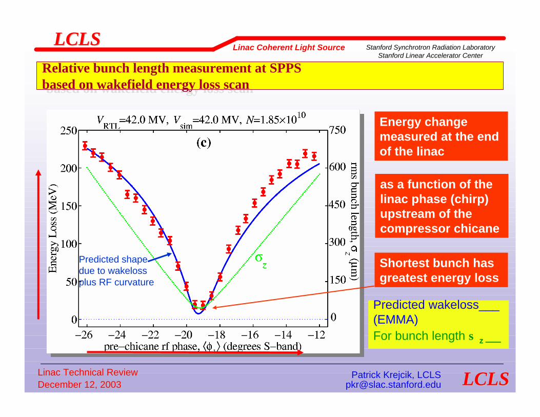
Relative bunch length measurement at SPPSbased on wakefield energy loss scan
Relative bunch length measurement at SPPSbased on wakefield energy loss scan
Energy change measured at the end of the linac
as a function of the linac phase (chirp) upstream of the compressor chicane
Shortest bunch has greatest energy loss
Predicted wakeloss___(EMMA)For bunch length σ z __
Predicted shape due to wakelossplus RF curvature

Linac Technical ReviewLinac Technical Review Patrick Krejcik, LCLSPatrick Krejcik, LCLSDecember 12, 2003December 12, 2003 [email protected]@slac.stanford.edu
LCLSLCLSLinac Coherent Light Source Stanford Synchrotron Radiation Laboratory
Stanford Linear Accelerator Center
LCLSLCLS
Bunch length and timing diagnosticsBunch length and timing diagnostics
Fast, single-bunch relative length measurementTHz spectral power
Coherent radiation from the bunch increases in power at shorter wavelengths as bunch length is reducedCoherent radiation detected as either
OTR from a thin foil – demonstrated at SLAC/SPPSCSR from a bend field – demonstrated at TJNAF
Difficult to calibrate as an absolute bunch length measurementBut relative changes in signal clearly show minimum bunch length in tuning scans
Simple spectral analysis showing power at different wavelengths can be used to tune to arbitrary wavelengths – under test DESY/SPPS
Fast, singleFast, single--bunch relative length measurementbunch relative length measurementTHz spectral powerTHz spectral power
Coherent radiation from the bunch increases in power at shorter Coherent radiation from the bunch increases in power at shorter wavelengths as wavelengths as bunch length is reducedbunch length is reducedCoherent radiation detected as eitherCoherent radiation detected as either
OTR from a thin foil OTR from a thin foil –– demonstrated at SLAC/SPPSdemonstrated at SLAC/SPPSCSR from a bend field CSR from a bend field –– demonstrated at TJNAFdemonstrated at TJNAF
Difficult to calibrate as an absolute bunch length measurementDifficult to calibrate as an absolute bunch length measurementBut relative changes in signal clearly show minimum bunch lengthBut relative changes in signal clearly show minimum bunch length in in tuning scanstuning scans
Simple spectral analysis showing power at different wavelengths Simple spectral analysis showing power at different wavelengths can be used to can be used to tune to arbitrary wavelengths tune to arbitrary wavelengths –– under test DESY/SPPSunder test DESY/SPPS

Linac Technical ReviewLinac Technical Review Patrick Krejcik, LCLSPatrick Krejcik, LCLSDecember 12, 2003December 12, 2003 [email protected]@slac.stanford.edu
LCLSLCLSLinac Coherent Light Source Stanford Synchrotron Radiation Laboratory
Stanford Linear Accelerator Center
LCLSLCLS
Bunch length and timing diagnosticsBunch length and timing diagnostics
THz spectral powerOTR issues studied at SPPS
Intercepting thin foil (OTR) versus foil with hole (ODR)Wavelength response of vacuum window
Fused silicaMylar foil vacuum windowWindow diameter
Wavelength response of water vaporDry nitrogen blanket
THz spectral powerTHz spectral powerOTR issues studied at SPPSOTR issues studied at SPPS
Intercepting thin foil (OTR) versus foil with hole (ODR)Intercepting thin foil (OTR) versus foil with hole (ODR)Wavelength response of vacuum windowWavelength response of vacuum window
Fused silicaFused silicaMylar foil vacuum windowMylar foil vacuum windowWindow diameterWindow diameter
Wavelength response of water vaporWavelength response of water vaporDry nitrogen blanketDry nitrogen blanket
Hole experiment!

Linac Technical ReviewLinac Technical Review Patrick Krejcik, LCLSPatrick Krejcik, LCLSDecember 12, 2003December 12, 2003 [email protected]@slac.stanford.edu
LCLSLCLSLinac Coherent Light Source Stanford Synchrotron Radiation Laboratory
Stanford Linear Accelerator Center
LCLSLCLS
Far-Infrared Detection of Wakefields from Ultra-Short BunchesFar-Infrared Detection of Wakefields from Ultra-Short Bunches
Wakefield diffraction radiation wavelength comparable
to bunch length
Pyroelectricdetector
foilLINAC
FFTB
Comparison of bunch length minimized according to
wakefield loss and THz power
GADC
-26 -24 -22 -20 -18 -16 -14 -120
100
200
300
400
500
600P
yrom
eter
sig
nal [
arb.
uni
ts]
linac phase offset from crest [deg. S-Band]
FFTB Pyrometer Signal
-26 -24 -22 -20 -18 -16 -14 -12200
250
300
350
400
450
500
ener
gy lo
ss [M
eV]
Linac Wake Loss
Linac phase
Wake energy loss
THz power

Linac Technical ReviewLinac Technical Review Patrick Krejcik, LCLSPatrick Krejcik, LCLSDecember 12, 2003December 12, 2003 [email protected]@slac.stanford.edu
LCLSLCLSLinac Coherent Light Source Stanford Synchrotron Radiation Laboratory
Stanford Linear Accelerator Center
LCLSLCLS
Absolute bunch length determinationAbsolute bunch length determination
Average bunch length from CTR autocorrelation
Radiation from the OTR screen is focused into an interferometerOne arm of interferometer is movable, so two profiles are swept through each otherMeasured bunch length is calibrated in microns of arm motionAveraged over many pulses, so integrates any bunch length jitter
Average bunch length from CTR Average bunch length from CTR autocorrelationautocorrelation
Radiation from the OTR screen is Radiation from the OTR screen is focused into an interferometerfocused into an interferometerOne arm of interferometer is movable, One arm of interferometer is movable, so two profiles are swept through so two profiles are swept through each othereach otherMeasured bunch length is calibrated Measured bunch length is calibrated in microns of arm motionin microns of arm motionAveraged over many pulses, so Averaged over many pulses, so integrates any bunch length jitterintegrates any bunch length jitter
D1OAP
M1
M2
S1
S2
D2
Mylar window
D2/D1
M2 posn.
M. Hogan, P. Mugli
SPPS48 fs rms

Linac Technical ReviewLinac Technical Review Patrick Krejcik, LCLSPatrick Krejcik, LCLSDecember 12, 2003December 12, 2003 [email protected]@slac.stanford.edu
LCLSLCLSLinac Coherent Light Source Stanford Synchrotron Radiation Laboratory
Stanford Linear Accelerator Center
LCLSLCLS
Bunch length and timing diagnosticsBunch length and timing diagnostics
Microbunching diagnosticsAt exit of BC1 & BC2
Coherent transition radiationSpectral power measurementsmeasurements can resolve micron-sized substructure in the bunch, demonstrated at LEUTL at 0.5 um scale (Lumpkin)
Coherent synchrotron monitor from final BC bendSpectral power measurementsAnalyze as radiation from an edge
Microbunching diagnosticsMicrobunching diagnosticsAt exit of BC1 & BC2At exit of BC1 & BC2
Coherent transition radiationCoherent transition radiationSpectral power measurementsSpectral power measurementsmeasurements can resolve micronmeasurements can resolve micron--sized substructure in the bunch, sized substructure in the bunch, demonstrated at LEUTL at 0.5 um demonstrated at LEUTL at 0.5 um scale (Lumpkin) scale (Lumpkin)
Coherent synchrotron monitor from Coherent synchrotron monitor from final BC bendfinal BC bendSpectral power measurementsSpectral power measurementsAnalyze as radiation from an edgeAnalyze as radiation from an edge
Z. Huang: expect to observe microstructure at λ0/comp.fact
Z. Huang: expect to observe microstructure at λ0/comp.fact

Linac Technical ReviewLinac Technical Review Patrick Krejcik, LCLSPatrick Krejcik, LCLSDecember 12, 2003December 12, 2003 [email protected]@slac.stanford.edu
LCLSLCLSLinac Coherent Light Source Stanford Synchrotron Radiation Laboratory
Stanford Linear Accelerator Center
LCLSLCLS
Bunch length and timing diagnosticsBunch length and timing diagnostics
Absolute bunch length determination3-bunch measurement with transverse RF deflecting cavity
Tested at SPPSInitial transverse tilt to the bunch from transverse wakes requires measuring at both zero phase crossingsAbsolute calibration of bunch length
in units of screen dimensions versus deg. S-band
Resolution determined by ratio of RF vertical kick to vertical beam sizeAchieved 50 um resolution in SPPS at 28.5 GeV with 5 um emittance
1 Hz pulse stealing mode of operation (new) pulsed magnet deflects beam onto off-axis screen
Future option is an x-band Tcav. in the LTU
Absolute bunch length determinationAbsolute bunch length determination33--bunch measurement with transverse RF deflecting cavitybunch measurement with transverse RF deflecting cavity
Tested at SPPSTested at SPPSInitial transverse tilt to the bunch from transverse wakes requiInitial transverse tilt to the bunch from transverse wakes requires measuring at res measuring at both zero phase crossingsboth zero phase crossingsAbsolute calibration of bunch length Absolute calibration of bunch length
in units of screen dimensions versus deg. Sin units of screen dimensions versus deg. S--bandband
Resolution determined by ratio of RF vertical kick to vertical bResolution determined by ratio of RF vertical kick to vertical beam sizeeam sizeAchieved 50 um resolution in SPPS at 28.5 Achieved 50 um resolution in SPPS at 28.5 GeVGeV with 5 um emittancewith 5 um emittance
1 Hz pulse stealing mode of operation 1 Hz pulse stealing mode of operation (new) pulsed magnet deflects beam onto off(new) pulsed magnet deflects beam onto off--axis screenaxis screen
Future option is an xFuture option is an x--band band TcavTcav. in the LTU. in the LTU

Linac Technical ReviewLinac Technical Review Patrick Krejcik, LCLSPatrick Krejcik, LCLSDecember 12, 2003December 12, 2003 [email protected]@slac.stanford.edu
LCLSLCLSLinac Coherent Light Source Stanford Synchrotron Radiation Laboratory
Stanford Linear Accelerator Center
LCLSLCLS
Bunch Length Measurements with the RF Transverse Deflecting CavityBunch Length Measurements with the RF Transverse Deflecting Cavity
σσ yy
Asymmetric parabola indicates incoming tilt to beam
A = 1.6696E-02 STD DEV = 1.3536E-03B = 28.23 STD DEV = 3.084C = 1328. STD DEV = 8.235RMS FIT ERROR = 23.63
-80 -40 0 40 80SBST LI29 1 PDES (S-29-1)
1.7
1.6
1.5
1.4
1.3
X103
****
***
**
**
*
****
********
0 40 80SBST LI29 1 PDES (S-29-1)
1.7
1.6
1.5
1.4
1.3
X103
E
0 40 80
1.7
1.6
1.5
1.4
1.3
X103
0 40 80
1.7
1.6
1.5
1.4
1.3
X103
0 40 80
1.7
1.6
1.5
1.4
1.3
X103
0 40 80
1.7
1.6
1.5
1.4
1.3
X103
E
1-APR-03 20:21:16
Cavity on
Cavity off
Cavity on- 180°
Bunch length reconstructionMeasure streak at 3 different phases
σz = 90 µm
(Str
eak
size
)2
0 ° 1 8 0 °
2.4 m 30 MW

Linac Technical ReviewLinac Technical Review Patrick Krejcik, LCLSPatrick Krejcik, LCLSDecember 12, 2003December 12, 2003 [email protected]@slac.stanford.edu
LCLSLCLSLinac Coherent Light Source Stanford Synchrotron Radiation Laboratory
Stanford Linear Accelerator Center
LCLSLCLS
Calibration scan for RF transverse deflecting cavityCalibration scan for RF transverse deflecting cavity
Beam centroid[pixels]
Cavity phase [deg. S-Band]
• Bunch lenghtcalibrated in units of the wavelength of the S-band RF
Further requirements for LCLS:
•High resolution OTR screen•Wide angle, linear view optics

Linac Technical ReviewLinac Technical Review Patrick Krejcik, LCLSPatrick Krejcik, LCLSDecember 12, 2003December 12, 2003 [email protected]@slac.stanford.edu
LCLSLCLSLinac Coherent Light Source Stanford Synchrotron Radiation Laboratory
Stanford Linear Accelerator Center
LCLSLCLS
Slice parameters from transverse RF deflecting cavitySlice parameters from transverse RF deflecting cavity
OTR screen down stream of the Tcav. can be used in conjunction with a quadrupole scan to measure horizontal slice emittance
OTR screen down stream of the Tcav. At a horizontal dispersion location, large ηx, small βx, can measure slice energy spread
OTR screen down stream of the OTR screen down stream of the TcavTcav. can be used in . can be used in conjunction with a quadrupole scan to measure horizontal conjunction with a quadrupole scan to measure horizontal slice emittanceslice emittance
OTR screen down stream of the OTR screen down stream of the TcavTcav. At a horizontal . At a horizontal dispersion location, large dispersion location, large ηηxx, small , small ββxx, can measure slice , can measure slice energy spreadenergy spread
σx(β)Distance along the bunch
Distance along the bunch
∆Ε

Linac Technical ReviewLinac Technical Review Patrick Krejcik, LCLSPatrick Krejcik, LCLSDecember 12, 2003December 12, 2003 [email protected]@slac.stanford.edu
LCLSLCLSLinac Coherent Light Source Stanford Synchrotron Radiation Laboratory
Stanford Linear Accelerator Center
LCLSLCLS
Bunch length and timing diagnosticsBunch length and timing diagnostics
Absolute bunch length determinationSingle shot electro optic pump probe measurement
Transforms the problem of measuring short electron bunch length to measuring a short pulse of laser light.Electro-optic process is inherently fast, < 2 fsTime resolution is dependant on crystal geometry and laser BWInvestigating two geometries at SPPSFemtosecond laser systems are complexInnovation at SPPS is transport a compressed beam to the e- beamline with a long fiber
Absolute bunch length determinationAbsolute bunch length determinationSingle shot electro optic pump probe measurementSingle shot electro optic pump probe measurement
Transforms the problem of measuring short electron bunch length Transforms the problem of measuring short electron bunch length to measuring a to measuring a short pulse of laser light.short pulse of laser light.ElectroElectro--optic process is inherently fast, < 2 fsoptic process is inherently fast, < 2 fsTime resolution is dependant on crystal geometry and laser BWTime resolution is dependant on crystal geometry and laser BWInvestigating two geometries at SPPSInvestigating two geometries at SPPSFemtosecond laser systems are complexFemtosecond laser systems are complexInnovation at SPPS is transport a compressed beam to the eInnovation at SPPS is transport a compressed beam to the e-- beamline with a beamline with a long fiberlong fiber

Linac Technical ReviewLinac Technical Review Patrick Krejcik, LCLSPatrick Krejcik, LCLSDecember 12, 2003December 12, 2003 [email protected]@slac.stanford.edu
LCLSLCLSLinac Coherent Light Source Stanford Synchrotron Radiation Laboratory
Stanford Linear Accelerator Center
LCLSLCLS
Electro Optic Bunch Length Measurement
Probe laser
Defining aperture
Beam axis
M1 M2EO xtal
Geometry chosen to measure direct
electric field from bunch, not wakefieldModelled by H. Schlarb
electrons

Linac Technical ReviewLinac Technical Review Patrick Krejcik, LCLSPatrick Krejcik, LCLSDecember 12, 2003December 12, 2003 [email protected]@slac.stanford.edu
LCLSLCLSLinac Coherent Light Source Stanford Synchrotron Radiation Laboratory
Stanford Linear Accelerator Center
LCLSLCLS
Resolution limit in temporal-to-spectral translationResolution limit in temporal-to-spectral translation
0res CT T T=BW limited pulse Short chirp
Long chirp
Temporal profile
Spectral profiles
However, recent work shows this limit can be overcome with noncollinear cross correlation of the light before and after the EO crystal
S.P. Jamison, Optics Letters, 28, 1710, 2003

Linac Technical ReviewLinac Technical Review Patrick Krejcik, LCLSPatrick Krejcik, LCLSDecember 12, 2003December 12, 2003 [email protected]@slac.stanford.edu
LCLSLCLSLinac Coherent Light Source Stanford Synchrotron Radiation Laboratory
Stanford Linear Accelerator Center
LCLSLCLS
ErEr
P
Elevation view End view
Plan view
electrons
EO Xtal
Er
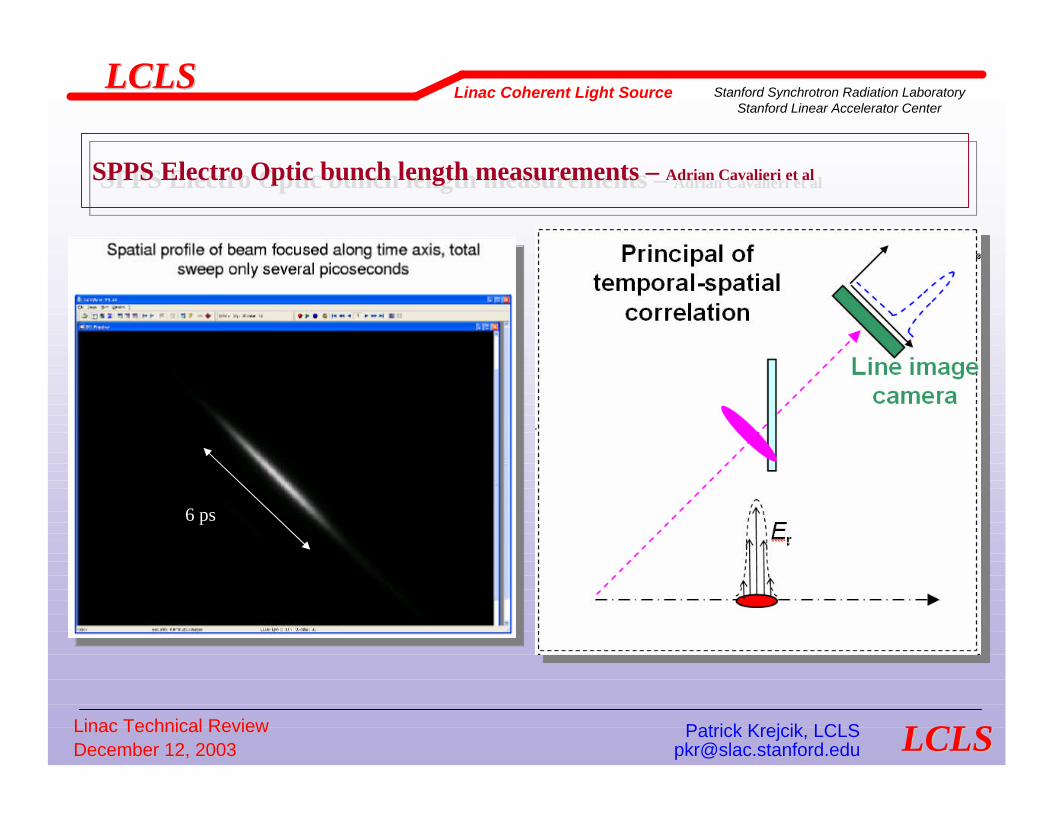
Principal oftemporal-spatial
correlation
Line image camera
Temporal to spatial geometry under test at SPPSTemporal to spatial geometry under test at SPPS
Linac Technical ReviewLinac Technical Review Patrick Krejcik, LCLSPatrick Krejcik, LCLSDecember 12, 2003December 12, 2003 [email protected]@slac.stanford.edu
LCLSLCLSLinac Coherent Light Source Stanford Synchrotron Radiation Laboratory
Stanford Linear Accelerator Center
LCLSLCLS
SPPS Electro Optic bunch length measurements – Adrian Cavalieri et alSPPS Electro Optic bunch length measurements – Adrian Cavalieri et al
6 ps

Linac Technical ReviewLinac Technical Review Patrick Krejcik, LCLSPatrick Krejcik, LCLSDecember 12, 2003December 12, 2003 [email protected]@slac.stanford.edu
LCLSLCLSLinac Coherent Light Source Stanford Synchrotron Radiation Laboratory
Stanford Linear Accelerator Center
LCLSLCLS
SPPS - EO signal vs time and single bunchSPPS - EO signal vs time and single bunch• thick crystal with long bunch > 1 ps
Linac Technical ReviewLinac Technical Review Patrick Krejcik, LCLSPatrick Krejcik, LCLSDecember 12, 2003December 12, 2003 [email protected]@slac.stanford.edu
LCLSLCLSLinac Coherent Light Source Stanford Synchrotron Radiation Laboratory
Stanford Linear Accelerator Center
LCLSLCLS
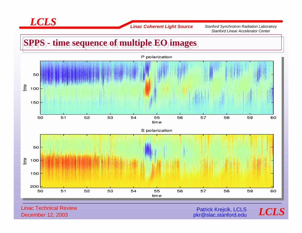
SPPS - time sequence of multiple EO imagesSPPS - time sequence of multiple EO images

Linac Technical ReviewLinac Technical Review Patrick Krejcik, LCLSPatrick Krejcik, LCLSDecember 12, 2003December 12, 2003 [email protected]@slac.stanford.edu
LCLSLCLSLinac Coherent Light Source Stanford Synchrotron Radiation Laboratory
Stanford Linear Accelerator Center
LCLSLCLS
ControlsModes of beam operation
1. No beam, injector in controlled accesslaser to cathode permissive, but no high-power RF permissive
2. Injector operation with beam to the sector 21 dump in the linac housing1 nC at 120 Hz maximum
3. Beam to the BSY, stopped in the BSY1 nC at 120 Hz maximum
4. Beam to the LTU (linac to undulator) single bunch beam dump1 nC at 120 Hz maximum
5. Beam to the undulator entrance tune-up dump1 nC at 10 Hz maximum
6. Beam to the final beam dump1 nC at 120 Hz maximum
Modes of beam operationModes of beam operation1.1. No beam, injector in controlled accessNo beam, injector in controlled access
laser to cathode permissive, but no highlaser to cathode permissive, but no high--power RF permissivepower RF permissive
2.2. Injector operation with beam to the sector 21 dump in the linacInjector operation with beam to the sector 21 dump in the linac housinghousing1 1 nCnC at 120 Hz maximumat 120 Hz maximum
3.3. Beam to the BSY, stopped in the BSYBeam to the BSY, stopped in the BSY1 1 nCnC at 120 Hz maximumat 120 Hz maximum
4.4. Beam to the LTU (linac to undulator) single bunch beam dumpBeam to the LTU (linac to undulator) single bunch beam dump1 1 nCnC at 120 Hz maximumat 120 Hz maximum
5.5. Beam to the undulator entrance tuneBeam to the undulator entrance tune--up dumpup dump1 1 nCnC at 10 Hz maximumat 10 Hz maximum
6.6. Beam to the final beam dumpBeam to the final beam dump1 1 nCnC at 120 Hz maximumat 120 Hz maximum
Laser
Injector dump
BSY dump
linac
dump
Muon shield
BSY
DL2
SBBD
undulator
Tune-up
dump
1
2 3 4 5 6

Linac Technical ReviewLinac Technical Review Patrick Krejcik, LCLSPatrick Krejcik, LCLSDecember 12, 2003December 12, 2003 [email protected]@slac.stanford.edu
LCLSLCLSLinac Coherent Light Source Stanford Synchrotron Radiation Laboratory
Stanford Linear Accelerator Center
LCLSLCLS
Controls
Timing requirementsChoice of frequencies
The linac RF operates at 2856 MHzThe laser for the RF photoinjector will be synchronized to the 24th subharmonicat 119 MHz
The timing system counts cycles of 119 MHz and can be adjusted in inter periods of this frequency, giving a timing step size of 8.4 ns.Time slots chosen to avoid PEP II phase shifts on the MDL
Preferable solution is if PEP II phase shifts are removed from MDL
Trigger resolution of 8.4 ns and stability of 10 ps adequateAlthough doesn’t provide absolute RF bucket determination
Pulse identification, buffering and feedbackRF phase locking and stability
Timing requirementsTiming requirementsChoice of frequenciesChoice of frequencies
The linac RF operates at 2856 MHzThe linac RF operates at 2856 MHzThe laser for the RF photoinjector will be synchronized to the 2The laser for the RF photoinjector will be synchronized to the 24th 4th subharmonicsubharmonicat 119 MHzat 119 MHz
The timing system counts cycles of 119 MHz and can be adjusted iThe timing system counts cycles of 119 MHz and can be adjusted in n inter periods of this frequency, giving a timing step size of 8.inter periods of this frequency, giving a timing step size of 8.4 ns.4 ns.Time slots chosen to avoid PEP II phase shifts on the MDLTime slots chosen to avoid PEP II phase shifts on the MDL
Preferable solution is if PEP II phase shifts are removed from MPreferable solution is if PEP II phase shifts are removed from MDLDL
Trigger resolution of 8.4 ns and stability of 10 Trigger resolution of 8.4 ns and stability of 10 psps adequateadequateAlthough doesn’t provide absolute RF bucket determinationAlthough doesn’t provide absolute RF bucket determination
Pulse identification, buffering and feedbackPulse identification, buffering and feedbackRF phase locking and stabilityRF phase locking and stability

Linac Technical ReviewLinac Technical Review Patrick Krejcik, LCLSPatrick Krejcik, LCLSDecember 12, 2003December 12, 2003 [email protected]@slac.stanford.edu
LCLSLCLSLinac Coherent Light Source Stanford Synchrotron Radiation Laboratory
Stanford Linear Accelerator Center
LCLSLCLS
Controls - system architecture requirements
How to preserve single pulse reading and id in a shared SLC/Epics systemHow to preserve single pulse reading and id in a shared How to preserve single pulse reading and id in a shared SLC/Epics systemSLC/Epics system
VMS operating system SLC Control Program
System support software
Network protocols database
Facilities software
application software
SCP displays
µ-processor camac crate
MPG µ-processor
Star network Communication line
Low level RF distribution
timing
Workstations OS: SunOS, Solaris HPUX DEC-UNIX SGIX Windows NT Linux
I/O Controllers OS: vxWorks
Field I/O Field I/O Field I/O Field I/O
ethernet
SLCEPICS
•Preserve the phase-locked timing fiducials carried by the SLAC low-level RF•And the multi-tasking beam pattern broadcast

Linac Technical ReviewLinac Technical Review Patrick Krejcik, LCLSPatrick Krejcik, LCLSDecember 12, 2003December 12, 2003 [email protected]@slac.stanford.edu
LCLSLCLSLinac Coherent Light Source Stanford Synchrotron Radiation Laboratory
Stanford Linear Accelerator Center
LCLSLCLS
Control system hybrid
Requires multi-protocol support on the LANRequires multiRequires multi--protocol support on the LANprotocol support on the LAN
API Application Program Interface
Device Class Libraries
Device Class Libraries VME Crate
CPU + Hard Drive EPICS IOC
CAMAC Crate
ENS Equipment Name Server
EPICS Display
API Library
PLC Programmable Logic Controller
e.g. MPS
LabView Display VI Library
API Library
Matlab Display
API Library
SCP SLC Control Program
SDDS Display SDDS toolkit Library
API Library
RPC CA
RPC
RPC
RPC
RPC CA
?
RPC
RPC CA
RPC CA
RPC CA
LAN Ethernet backbone
RF distribution
timing
fiducial
Linac Technical ReviewLinac Technical Review Patrick Krejcik, LCLSPatrick Krejcik, LCLSDecember 12, 2003December 12, 2003 [email protected]@slac.stanford.edu
LCLSLCLSLinac Coherent Light Source Stanford Synchrotron Radiation Laboratory
Stanford Linear Accelerator Center
LCLSLCLS
Controls - Low level RF
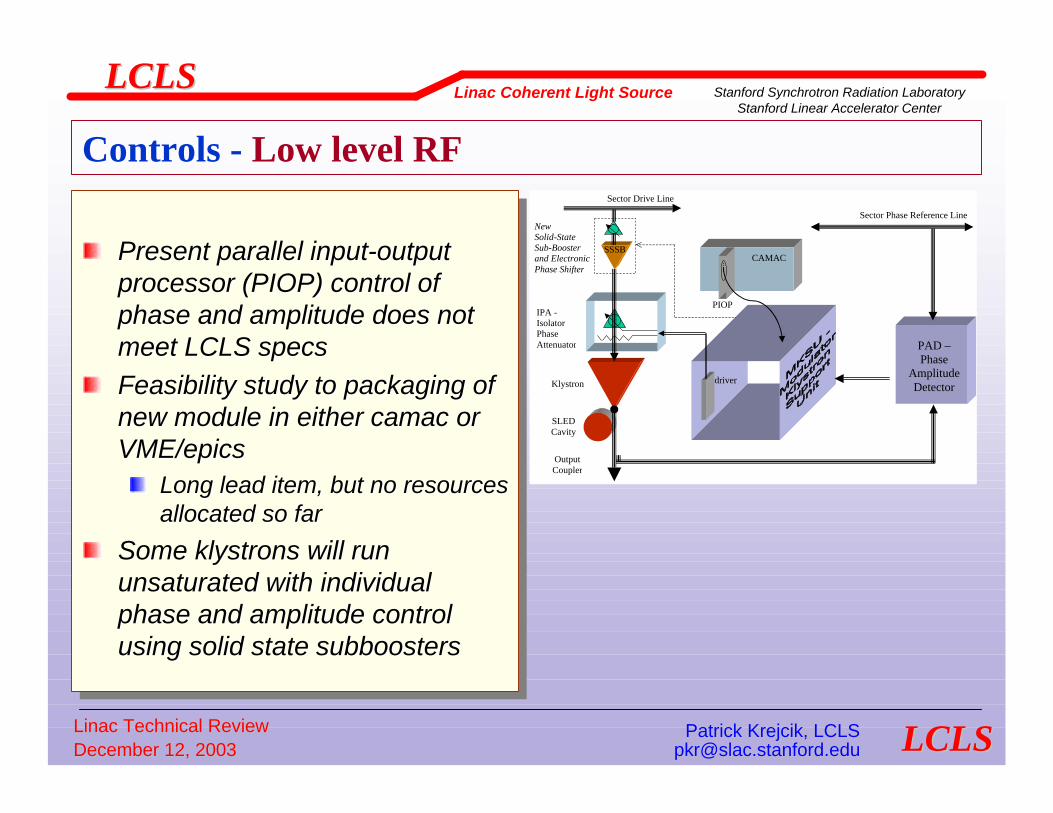
Present parallel input-output processor (PIOP) control of phase and amplitude does not meet LCLS specsFeasibility study to packaging of new module in either camac or VME/epics
Long lead item, but no resources allocated so far
Some klystrons will run unsaturated with individual phase and amplitude control using solid state subboosters
Present parallel inputPresent parallel input--output output processor (PIOP) control of processor (PIOP) control of phase and amplitude does not phase and amplitude does not meet LCLS specsmeet LCLS specsFeasibility study to packaging of Feasibility study to packaging of new module in either new module in either camaccamac or or VME/epicsVME/epics
Long lead item, but no resources Long lead item, but no resources allocated so farallocated so far
Some klystrons will run Some klystrons will run unsaturated with individual unsaturated with individual phase and amplitude control phase and amplitude control using solid state using solid state subboosterssubboosters
PAD – Phase
Amplitude Detector
Sector Phase Reference Line
Klystron
SLED Cavity
Output Coupler
IPA - Isolator Phase Attenuator
Sector Drive Line
CAMAC
PIOP
driver
SSSB
New Solid-State Sub-Booster and ElectronicPhase Shifter

Linac Technical ReviewLinac Technical Review Patrick Krejcik, LCLSPatrick Krejcik, LCLSDecember 12, 2003December 12, 2003 [email protected]@slac.stanford.edu
LCLSLCLSLinac Coherent Light Source Stanford Synchrotron Radiation Laboratory
Stanford Linear Accelerator Center
LCLSLCLS
Controls - Low level RF
Low-noise, low-drift RF source in sect 20Change from CDR, now lock at 119 MHz
LowLow--noise, lownoise, low--drift RF source in sect 20drift RF source in sect 20Change from CDR, now lock at 119 MHzChange from CDR, now lock at 119 MHz
Master Oscillator
8.5 MHz Xtal
x56 Fiducial
Generator
476 MHz 1/360 s
PEP Timing
Generator
8.5 MHz
60 W
Sector 0 Sector 20
Main Drive Line
360 Hz
Trigger Generator
Laser Mode Lock 119 MHz
Laser Trig
Gun
Klystron
LCLS Master Oscillator
119 MHz Xtal
X4
x6 476
MHz
New LCLS Experiments Trigger Gen.
Laser Trig
119 MHz
Σ
2856 MHz
1/120 s
Fiber Optic Driver
To LCLS Experiments
2856 MHz
Gated Lock
To L0, L1 klystrons
Fiber Optic coupler
To LCLS Exp. laser
119 MHz
Linac Technical ReviewLinac Technical Review Patrick Krejcik, LCLSPatrick Krejcik, LCLSDecember 12, 2003December 12, 2003 [email protected]@slac.stanford.edu
LCLSLCLSLinac Coherent Light Source Stanford Synchrotron Radiation Laboratory
Stanford Linear Accelerator Center
LCLSLCLS
Controls - Low level RF
Low-noise, low-drift RF oscillator issuesOscillator and distribution housed in thermally stabilized enclosure
In spite of this there will be some drift requiring beam-based feedback
Advances in technology have allowed us to choose 119 MHz over previous 79.33 MHz
Greatly simplifies timing system as we are now in synchronization with existing timing fiducialsBig advantage for experimenters who can mode lock their lasers to photoinjector laser with 119 MHz optical pulses and always be in the same RF bucketLesson learned from SPPS that exp laser is susceptible to bucket jumps
LCLS will operate on a different time slot from PEP IIAvoid phase jumps on MDL during PEP injectionFeasibility study to reconfigure phase shifters and avoid MDL phase jumps
LowLow--noise, lownoise, low--drift RF oscillator issuesdrift RF oscillator issuesOscillator and distribution housed in thermally stabilized encloOscillator and distribution housed in thermally stabilized enclosuresure
In spite of this there will be some drift requiring beamIn spite of this there will be some drift requiring beam--based feedbackbased feedback
Advances in technology have allowed us to choose 119 MHz over Advances in technology have allowed us to choose 119 MHz over previous 79.33 MHzprevious 79.33 MHz
Greatly simplifies timing system as we are now in synchronizatioGreatly simplifies timing system as we are now in synchronization with existing n with existing timing timing fiducialsfiducialsBig advantage for experimenters who can mode lock their lasers tBig advantage for experimenters who can mode lock their lasers to photoinjector o photoinjector laser with 119 MHz optical pulses and always be in the same RF blaser with 119 MHz optical pulses and always be in the same RF bucketucketLesson learned from SPPS that exp laser is susceptible to bucketLesson learned from SPPS that exp laser is susceptible to bucket jumpsjumps
LCLS will operate on a different time slot from PEP IILCLS will operate on a different time slot from PEP IIAvoid phase jumps on MDL during PEP injectionAvoid phase jumps on MDL during PEP injectionFeasibility study to reconfigure phase shifters and avoid MDL phFeasibility study to reconfigure phase shifters and avoid MDL phase jumpsase jumps
Linac Technical ReviewLinac Technical Review Patrick Krejcik, LCLSPatrick Krejcik, LCLSDecember 12, 2003December 12, 2003 [email protected]@slac.stanford.edu
LCLSLCLSLinac Coherent Light Source Stanford Synchrotron Radiation Laboratory
Stanford Linear Accelerator Center
LCLSLCLS
Controls
Feedback requirements. Pulse-to-pulse control of
Orbit position & angle, energy as in SLC
beam phase, Necessary, for example, to measure orbit after RF deflecting cavity to maintain cavity at zero phase crossing
bunch lengthUse relative signal strength from OTR THz spectral power measurementDemonstrated at SPPS with dither feedback to minimize bunch lengthNeeds power measurement at several THz wavelengths to tune to arbitrary bunch lengthsDecouple longitudinal feedback requirements
Energy feedback maintains constant energy at the BC chicaneBunch length feedback controls the linac phase (energy chirp)
Feedback requirements. Feedback requirements. PulsePulse--toto--pulse control ofpulse control of
Orbit position & angle, energy Orbit position & angle, energy as in SLCas in SLC
beam phase, beam phase, Necessary, for example, to measure orbit after RF deflecting cavNecessary, for example, to measure orbit after RF deflecting cavity to ity to maintain cavity at zero phase crossing maintain cavity at zero phase crossing
bunch lengthbunch lengthUse relative signal strength from OTR THz spectral power measureUse relative signal strength from OTR THz spectral power measurementmentDemonstrated at SPPS with dither feedback to minimize bunch lengDemonstrated at SPPS with dither feedback to minimize bunch lengththNeeds power measurement at several THz wavelengths to tune to arNeeds power measurement at several THz wavelengths to tune to arbitrary bitrary bunch lengthsbunch lengthsDecouple longitudinal feedback requirementsDecouple longitudinal feedback requirements
Energy feedback maintains constant energy at the BC chicaneEnergy feedback maintains constant energy at the BC chicaneBunch length feedback controls the linac phase (energy chirp)Bunch length feedback controls the linac phase (energy chirp)

Linac Technical ReviewLinac Technical Review Patrick Krejcik, LCLSPatrick Krejcik, LCLSDecember 12, 2003December 12, 2003 [email protected]@slac.stanford.edu
LCLSLCLSLinac Coherent Light Source Stanford Synchrotron Radiation Laboratory
Stanford Linear Accelerator Center
LCLSLCLS
Energy feedback at SPPS chicane responding to a step energy change
Energy feedback at SPPS chicane responding to a step energy change
Klystron off on
Energy measured at a dispersive BPM,Actuator is a klystron phase shifter
Energy measured at a dispersive BPM,Actuator is a klystron phase shifter
Klystron 1 Klystron 2
+φ−φ
Controls – Energy feedback
Energy jitter measured from chicane feedback system 5.6 MeV rms
0.06%
Energy jitter measured from chicane feedback system 5.6 MeV rms
0.06%
Linac Technical ReviewLinac Technical Review Patrick Krejcik, LCLSPatrick Krejcik, LCLSDecember 12, 2003December 12, 2003 [email protected]@slac.stanford.edu
LCLSLCLSLinac Coherent Light Source Stanford Synchrotron Radiation Laboratory
Stanford Linear Accelerator Center
LCLSLCLS
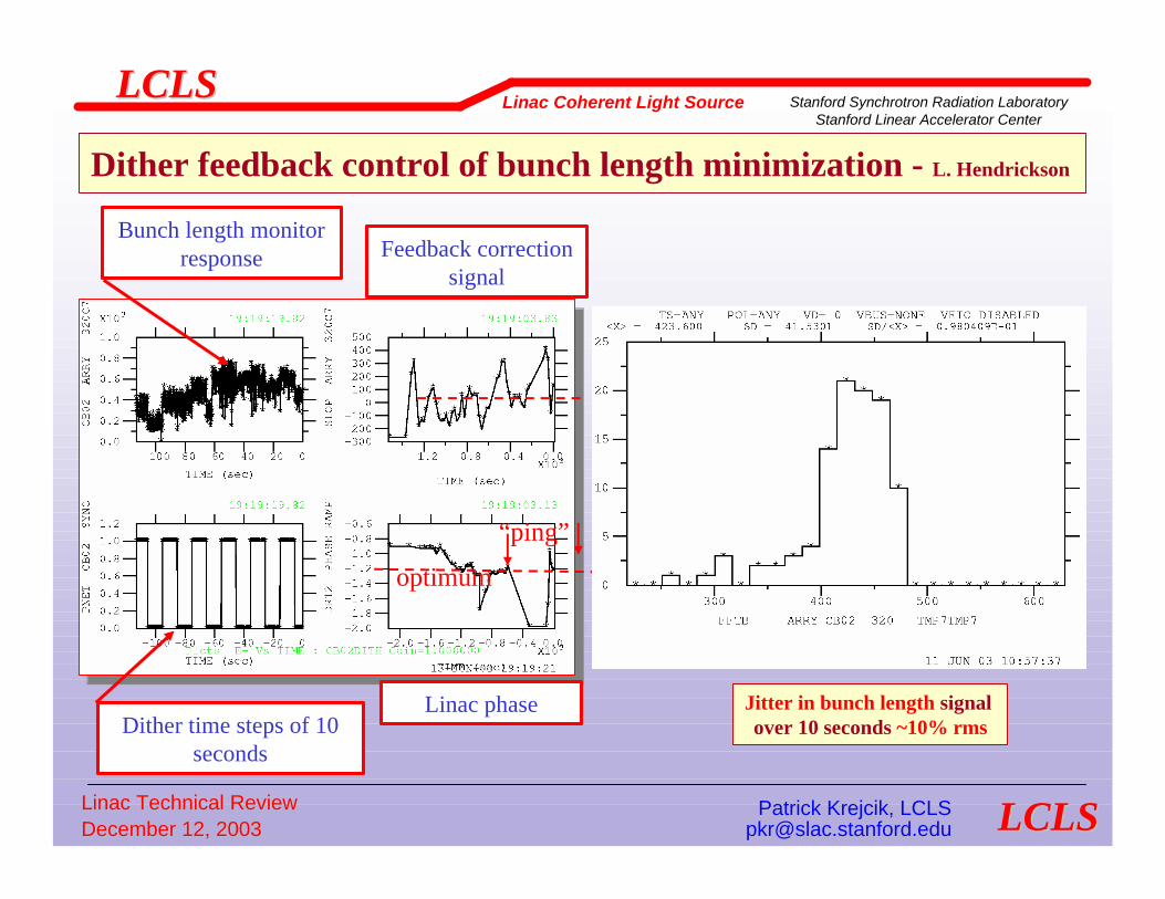
Dither feedback control of bunch length minimization - L. HendricksonDither feedback control of bunch length minimization - L. Hendrickson
Dither time steps of 10 seconds
Bunch length monitor response Feedback correction
signal
Linac phase
“ping”
optimum
Jitter in bunch length signal over 10 seconds ~10% rms
Jitter in bunch length signal over 10 seconds ~10% rms

Linac Technical ReviewLinac Technical Review Patrick Krejcik, LCLSPatrick Krejcik, LCLSDecember 12, 2003December 12, 2003 [email protected]@slac.stanford.edu
LCLSLCLSLinac Coherent Light Source Stanford Synchrotron Radiation Laboratory
Stanford Linear Accelerator Center
LCLSLCLS
Controls
MPSStoppers and beam dumpers (tune-up dumps)
Injector energy spectrometer (full rate)BSY, D2 (full rate)Exit of muon shield, formerly known as ST61 (10 Hz)Single bunch beam dumper (SBBD) after LTU dogleg (full rate)
SLC design
End of LTU (10 Hz)
Bunch compressor MPSPLIC, PICs, Av. Current monitor comparator interlocked to gun rate control
LTU Collimator MPSPLIC, PICs interlocked to SBBDAllows full rate in the linac and arbitrary rate to the undulator
MPSMPSStoppers and beam dumpers (tuneStoppers and beam dumpers (tune--up dumps)up dumps)
Injector energy spectrometer (full rate)Injector energy spectrometer (full rate)BSY, D2 (full rate)BSY, D2 (full rate)Exit of muon shield, formerly known as ST61 (10 Hz)Exit of muon shield, formerly known as ST61 (10 Hz)Single bunch beam dumper (SBBD) after LTU dogleg (full rate)Single bunch beam dumper (SBBD) after LTU dogleg (full rate)
SLC designSLC design
End of LTU (10 Hz)End of LTU (10 Hz)
Bunch compressor MPSBunch compressor MPSPLIC, PLIC, PICsPICs, Av. Current monitor comparator interlocked to gun rate control, Av. Current monitor comparator interlocked to gun rate control
LTU Collimator MPSLTU Collimator MPSPLIC, PLIC, PICsPICs interlocked to SBBDinterlocked to SBBDAllows full rate in the linac and arbitrary rate to the undulatoAllows full rate in the linac and arbitrary rate to the undulatorr

Linac Technical ReviewLinac Technical Review Patrick Krejcik, LCLSPatrick Krejcik, LCLSDecember 12, 2003December 12, 2003 [email protected]@slac.stanford.edu
LCLSLCLSLinac Coherent Light Source Stanford Synchrotron Radiation Laboratory
Stanford Linear Accelerator Center
LCLSLCLS
Controls
PPS zonesPPS zonesPPS zones
3. BSY + Sect. 30
1. injector
Shield wall
2. LINAC
Laser Key entrance gate
Sector entrances
gate muon shield
PPS Key entrance gate
4. LTU gate 5. undulator gate 6. FEE
PPS Key entrance gate
PPS Key entrance gate
7. Near Hall x-ray transport 8. Far Hall
Equipment & emergency gate
20-21 22-23 24-25 26-27 28-29
PPS Key entrance gate
BAS II stopper
D2 stopper
Injector stopper
Dump

Linac Technical ReviewLinac Technical Review Patrick Krejcik, LCLSPatrick Krejcik, LCLSDecember 12, 2003December 12, 2003 [email protected]@slac.stanford.edu
LCLSLCLSLinac Coherent Light Source Stanford Synchrotron Radiation Laboratory
Stanford Linear Accelerator Center
LCLSLCLS
Controls - PPS
Linac Technical ReviewLinac Technical Review Patrick Krejcik, LCLSPatrick Krejcik, LCLSDecember 12, 2003December 12, 2003 [email protected]@slac.stanford.edu
LCLSLCLSLinac Coherent Light Source Stanford Synchrotron Radiation Laboratory
Stanford Linear Accelerator Center
LCLSLCLS
Controls - PPS
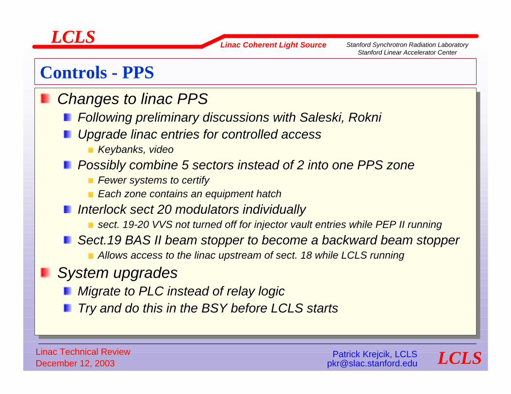
Changes to linac PPSFollowing preliminary discussions with Saleski, RokniUpgrade linac entries for controlled access
Keybanks, video
Possibly combine 5 sectors instead of 2 into one PPS zoneFewer systems to certifyEach zone contains an equipment hatch
Interlock sect 20 modulators individually sect. 19-20 VVS not turned off for injector vault entries while PEP II running
Sect.19 BAS II beam stopper to become a backward beam stopperAllows access to the linac upstream of sect. 18 while LCLS running
System upgradesMigrate to PLC instead of relay logicTry and do this in the BSY before LCLS starts
Changes to linac PPSChanges to linac PPSFollowing preliminary discussions with Following preliminary discussions with SaleskiSaleski, , RokniRokniUpgrade linac entries for controlled accessUpgrade linac entries for controlled access
KeybanksKeybanks, video, video
Possibly combine 5 sectors instead of 2 into one PPS zonePossibly combine 5 sectors instead of 2 into one PPS zoneFewer systems to certifyFewer systems to certifyEach zone contains an equipment hatchEach zone contains an equipment hatch
Interlock sect 20 modulators individually Interlock sect 20 modulators individually sect. 19sect. 19--20 VVS not turned off for injector vault entries while PEP II ru20 VVS not turned off for injector vault entries while PEP II runningnning
Sect.19 BAS II beam stopper to become a backward beam stopperSect.19 BAS II beam stopper to become a backward beam stopperAllows access to the linac upstream of sect. 18 while LCLS runniAllows access to the linac upstream of sect. 18 while LCLS runningng
System upgradesSystem upgradesMigrate to PLC instead of relay logicMigrate to PLC instead of relay logicTry and do this in the BSY before LCLS startsTry and do this in the BSY before LCLS starts

Linac Technical ReviewLinac Technical Review Patrick Krejcik, LCLSPatrick Krejcik, LCLSDecember 12, 2003December 12, 2003 [email protected]@slac.stanford.edu
LCLSLCLSLinac Coherent Light Source Stanford Synchrotron Radiation Laboratory
Stanford Linear Accelerator Center
LCLSLCLS
Control Room
LCLS will double present occupancy and number of consolesFeasibility study to expand space by removing old racks and replacing with modular consoles
LCLS will double LCLS will double present occupancy present occupancy and number of and number of consolesconsolesFeasibility study to Feasibility study to expand space by expand space by removing old racks removing old racks and replacing with and replacing with modular consolesmodular consoles
Room 100
Room 112
Room 110 Room 114 N
1
2

Linac Technical ReviewLinac Technical Review Patrick Krejcik, LCLSPatrick Krejcik, LCLSDecember 12, 2003December 12, 2003 [email protected]@slac.stanford.edu
LCLSLCLSLinac Coherent Light Source Stanford Synchrotron Radiation Laboratory
Stanford Linear Accelerator Center
LCLSLCLS
ConclusionConclusion
Upgrades to conventional diagnostic instrumentation have been listedLinac relies heavily on several new and complex bunch length and timing diagnostics
Development work on these has started at SPPS
Control system faces challenge of compatibility with existing systems and integrating new, multi-protocol systems
Have defined the constraints this system faces, plus the requirements for LCLS, particularly the timing stabilitySome conceptual designs discussed for SLC/EPICS hybrid (Bob Dalaseio) but now needs engineering design
Upgrades to conventional diagnostic instrumentation have Upgrades to conventional diagnostic instrumentation have been listedbeen listedLinac relies heavily on several new and complex bunch Linac relies heavily on several new and complex bunch length and timing diagnosticslength and timing diagnostics
Development work on these has started at SPPSDevelopment work on these has started at SPPS
Control system faces challenge of compatibility with existing Control system faces challenge of compatibility with existing systems and integrating new, multisystems and integrating new, multi--protocol systemsprotocol systems
Have defined the constraints this system faces, plus the Have defined the constraints this system faces, plus the requirements for LCLS, particularly the timing stabilityrequirements for LCLS, particularly the timing stabilitySome conceptual designs discussed for SLC/EPICS hybrid (Bob Some conceptual designs discussed for SLC/EPICS hybrid (Bob DalaseioDalaseio) but now needs engineering design) but now needs engineering design