Embed Size (px)
Citation preview

T C10 095G or T C10 165G
Motor No:
Serial No:
Warranty Stipulations:
Copy of sales receipt mailed with this form
All warranty information, located on the front & back, filled out
FASS products and/or paperwork must not be tampered with
Warranties are non-transferable
Warranty is only available if purchased through FASS ViP Dealer! There is “NO Warranty”
on FASS Products purchased through unauthorized dealers.
Warranty Registration must be received by FASS within 30 days of purchase.
Manufactured Date:
Limited lifetime Warranty
Send Correspondence to:
FASS Fuel Systems
Attn: Warranty
16234 State Hwy O Marthasville, MO. 63357
Date Received:
Purchase Receipt: Yes (Receipt Date: ) No
DPP Inc. office use only :

Dealer Purchased From : Date:
New FASS Owner Name:
Company/Organization:
Phone:
Email:
Street:
City, State & Zip:
Vehicle Year/ Make/ Model:
Color:
Vin Number:
Comments:
Quality Of Product
Excellent Good Fair Poor
Dealer Magazine
Show Online Friend
How did you hear about us?

APPLICATION:T C10 095G (95GPH @ 8-10psi)
T C10 165G (165GPH @ 8-10psi)
Duramax 2500 & 3500Standard Pickup Truck
2001-2010
INSTALLATION MANUAL
**Note: Cab and Chassis may require modifications**
Revision Date: 10/24/2017

Dear Valued Customer,
“Made in the USA” is not just a slogan at FASS; it’s what we live by! FASS is not only
assembled in the USA but 98%+ of the FASS product is manufactured in the USA, helping to em-
ploy Americans and strengthen America. At FASS, we scrutinize our suppliers and demand the
highest quality American-made components. However, this does come at a price, which is one of
the main reasons FASS products are more expensive than the competition. Remember price does
not dictate quality but quality does dictate price! Here at FASS, we believe it’s worth the commit-
ment and will continue this practice to support America! Our competition is doing exactly the op-
posite by using foreign-made components.
Building extremely “High-Quality” fuel products is our business. We concentrate all of our
efforts in this arena. No one else is as specialized as FASS in what we do! This is one of the ingre-
dients to insure you are running with the “Highest-Quality” fuel system in the world! We have im-
plemented very rigorous testing procedures to provide the “Highest Quality” we have become
known for. Not only is our product superior, but customer satisfaction is #1 at FASS. It is our goal
to provide the best service possible. Our confidence is evident in the products we make as each
product is backed by an industry leading warranty!
Our R & D department, in conjunction with our Dealer Support department, is continually
searching for ways to improve quality, expand our product line, and provide superb support to our
network of dealers so our customers’ needs and expectations will be exceeded.
To help insure you receive the proper system and customer support at the local level, FASS
has a VIP and Authorized Dealer network representing FASS products. This is one reason you
must purchase through a dealer to comply with our warranty policies. If you do not, there is no
warranty! We recommend you go to www.FASSride.com, click “Find A Dealer”, put in their ZIP
code, select the type of dealer, and see if the company you purchased from is listed. If they are not,
put their phone number in the field below the ZIP code field to see if they are listed. Below these
two fields is a list of “Terminated/Unauthorized” dealers. You may want to review this list. If the
company is not listed or is on the “Terminated/Unauthorized” list, we suggest you return the prod-
uct immediately to that dealer and call FASS. We’ll recommend you to the nearest dealer.
VERY IMPORTANT: Make sure to fill out your product registration form and return the
original form to FASS Fuel Systems within 30 days of purchase accompanied with a copy of the
purchase receipt. Complying with these guidelines will qualify you for the Extended Warranty!
See the Owner’s Manual online at www.FASSride.com for full Limitation of Warranty. In
the event that the buyer does not agree with this agreement: the buyer may promptly return this
product, in a new and unused condition, with a dated receipt, to the place of purchase within thirty
(30) days from date of purchase for a full refund less shipping.
The installation of this product indicates that the buyer has read and understands the
Limitation of Warranty agreement and accepts its terms and conditions.

FASS Recommended Application
T C10 095G Duramax 2001-2010 with stock - moderate horse power modifications
T C10 165G Duramax 2001-2010 with moderate - extreme horsepower modifications
Note: Because of the higher fuel flow these systems have to offer, you may encounter
problems with the stock fuel module. FASS can solve this with a Suction Tube Kit.
Serial #
¡WARNINGs!
Read all instructions before starting installation of this product!
Installing the improper FASS Pump can cause severe engine damage.
Secure vehicle from ROLLING!
Cab and Chassis may require modifications
Consult vehicle’s manufacturers’ instructions concerning the electrical system before at-
tempting any electrical connections.
Be sure that the serial # on this installation manual matches that of the outside of the box.
Flush and clean all brass fittings and fuel line from debris.
Keep debris from entering the internals of the system during installation. Getting debris in
the water separator nipple can lock up the motor. If the motor does lock up from debris call
FASS for technical assistance.
Wear safety glasses when operating power tools such as drills and grinders or when using a
punch or chisel.
Properly secure lines to prevent chaffing.
BEFORE STARTING THE INSTALLATION PROCESS LUBRICATE THE
BED BOLT WITH WD-40 TO HELP WITH INSTALLATION

INSTALLATION MANUAL
Follow these steps to ensure a simple installation of your new
FASS TITANIUM FUEL SYSTEM
1. Read the installation manual completely before attempting installation. The in-
stallation of this product indicates that the buyer has read and understands the
limitations of the FASS manufacturers warranty agreement and accepts the re-
sponsibility of its terms and conditions.
2. Inventory the package components. Notify the place of purchase immediately of
any parts missing or damaged.
3. The installation recommendations contained herein are guidelines. Use good judg-
ment and take into consideration your vehicles' accessories.
4. For best results in accuracy and efficiency (due to training, communication, and our
relationship with our dealer network), we recommend a ViP FASS dealer for the
installation. They are prepared to install the FASS fuel pumps with the most effi-
ciency. If a situation/problem arises during the installation, they are the most pre-
pared for that situation/problem. DPPI is not responsible for any installation mis-
takes.
5. If you have any questions or concerns that can not be addressed with your dealer,
email or call FASS.
6. If any installation procedure is uncertain, contact FASS technical support.
Email [email protected] with the following information:
Your Name, address and daytime phone number
Model (T C10 095G or T C10 165G)
Serial Number
Vin Number of Vehicle
Date of purchase
Nature of Your Concern
Call customer service; 636-433-5410 with the following information:
Model (T C10 095G or T C10 165G)
Serial Number
Vin Number of Vehicle
Date of purchase
Serial # Found Here….

Titanium Series
Installation
Step 1: Install Electrical Harness
Step 2: Prepare Suction and Return Lines
Step 3: Mount Fuel System
Step 4: Install Fuel Line
Step 5: Check Installation
95 or 165 GPH
8-10 PSI (Approximately)
A fuel pressure gauge is highly recommended to identify fuel filter life and to prevent engine damage!
‘R’
Fuel Return to Tank
“E”
To Engine
Serial Number Location
‘G’
Fuel Pressure
‘T’
Fuel Inlet
Electric Heater
Port
“H”
Coolant Heater
2nd
Electric Heater Port

Contents
PBR-2001 PFB-2002
FL-1002 x14’
WH-1006
MP-9025

Mounting Package Contents
PL-1005
10-301 10-300
RM-1001 QD-1002 HC-1003
HC-1001
Ring Terminal
PLB-1212
*Cable Ties*
4 Hex Bolt 3/8” -16x 1 1/2” 3 Hex Bolt 1/4”-20x1 3/4” 4 Locking Nut 3/8” 3 WA-1001D 4 3/8” Washers
RS-2002 RS-2001
46044
46260

C. Crimp the ring terminals to the red and green wires of the WH-1006 Wire
Harness. Attach red wire to the positive terminal of the battery and the
green terminal to the negative terminal. The use of a corrosion preventa-
tive on electrical connections is recommended.
D. Secure relay and fuse in an upright position, as shown, to prevent
moisture from entering. Di-electric grease may be applied to prevent
corrosion.
FUSE
RELAY
Step 1: Install Electrical Harness The installation of the electrical harness is done first, allowing power to be applied to the pump for
lubrication purposes later in the installation.
A. Using wire stripping tool remove excess insulation off the add-a-fuse
and the WH-1006.
B. Place wire from 46044 and WH-1006 into butt connector. Using crimping tool connect 46044 and WH-
1006 with butt connector. Install 46260 to 46044 bottom slot (opening that is near the spade).
Before starting installation please review contents page to insure all necessary parts are included. Please
call Diesel Performance Products for any missing or incorrect items. 636-433-5410

E. If fuse panel is located in the cab it will be necessary to guide the single
red wire from the relay through the fire wall grommet to access the fuse pan-
el.
G. Route WH-1006 wire harness along frame rail to mounting location of pump. Completion of this step
will be addressed in the Mounting Step 3.
Step 1: Install Electrical Harness
F. Locate fuse box under hood and select ignition hot fuse. Remove fuse and put Add-A-Fuse in place.
Install fuse previously removed. The use of a corrosion preventative on electrical connections is recom-
mended.
Before starting installation please review contents page to insure all necessary parts are included. Please
call Diesel Performance Products for any missing or incorrect items. 636-433-5410

Step 2: Prepare suction & Return Lines
A. Remove the 3 bolts holding the factory Return Fuel cooler to the
mounting bracket. The fuel cooler is located in front of the fuel tank.
C. Using oil, insert PLB-1212 into one end of the provided FL-1002 fuel
line. Feed line over frame to the stock fuel connection.
D. Push the PLB-1212 into the factory suction line until you hear a click
and the tabs are locked in place.
E. Using an HC-1001 hose clamp, insert the QD-1002 into the other end of the provided FL-1002 fuel line
and secure. Loop this end over the frame to the factory steel fuel line disconnected in Step 2b. Oil the
rings inside the QD-1002 and slide over the line until you hear a click. Do not cut the line at this time.
B. Using a fuel line disconnect tool, disconnect the factory suction line
located above the fuel cooler. Place the disconnect tool around the
fuel tube and slide the tool under the fuel line connection to release
the fuel line.
NOTE: Hose clamps are not recommended for push lock fittings.
They will hold up to 300psi! Use oil on fittings and inside fuel line
when installing Push-Lok fittings
Some of the photo’s are of a different application, procedures are the same.
Before starting installation please review contents page to insure all necessary parts are included. Please
call Diesel Performance Products for any missing or incorrect items. 636-433-5410

Step 2: Prepare suction & Return Lines
F. Some filler necks have the integrated over-flow tube. If your filler neck
does not have a separate over-flow tube, you have an integrated filler neck. Mark
location for the Return manifold on the rubber over-flow tube. Loosen
the clamps on both ends of the filler neck and remove screws from
fuel receptacle. Remove filler neck assembly. Slide rubber outer hose
down exposing filler tube. At mark, cut hose. Make sure there is
enough tube on each side of the cut to insert the RM-1001 and to
place the hose clamps. Slide top half over filler tube with HC-1003
clamp. Slide RM-1001 Return Manifold over the filler tube and into
over-flow hose with the small junction pipe pointing toward the fend-
er. Slide another HC-1003 clamp and bottom hose over filler tube and
secure. Re-install filler neck assembly.
OR
Prepare FASS return line by cutting rubber junction connecting the
two halves of the filler neck. Position RM-1001 with the 1/2” junction
pipe aiming to outside of bed. Clamp rubber and RM-1001 using both
HC-1003’s.
G. Position RM-1001 with the junction pipe aiming to outside of bed.
Connect rubber and RM-1001using both HC-1003’s.
Before starting installation please review contents page to insure all necessary parts are included. Please
call Diesel Performance Products for any missing or incorrect items. 636-433-5410

NOTE
ATTENTION: While installing fittings into Titanium pump
DO NOT Apply side pressure to draw
tube of pump
Improper
Proper
Before starting installation please review contents page to insure all necessary parts are included. Please
call Diesel Performance Products for any missing or incorrect items. 636-433-5410

Step 3: Mount Fuel System
A. Install 10-300 into the "E" port and 10-301 into the "T" port of the FASS, torque to 18 ft./lbs.
***FITTINGS ARE EQUIPPED WITH SEALANT, DO NOT USE THREAD TAPE***
B. For fitting purposes. Secure PBR-2001 to pump assembly lightly with (3) 1/4”-20x1 3/4 bolts and (3)
WA-1001D. This will assembly will be used in future steps for correct fitting of brackets. (Note:
Bracket maybe flipped to accommodate your application.)
NOTE: Before installing fittings make sure to inspect for burs or flare imperfections.
When cutting fuel line make sure to blow out line to keep debris from moving forward.
Before starting installation please review contents page to insure all necessary parts are included. Please
call Diesel Performance Products for any missing or incorrect items. 636-433-5410
Step 3: Mount Fuel System
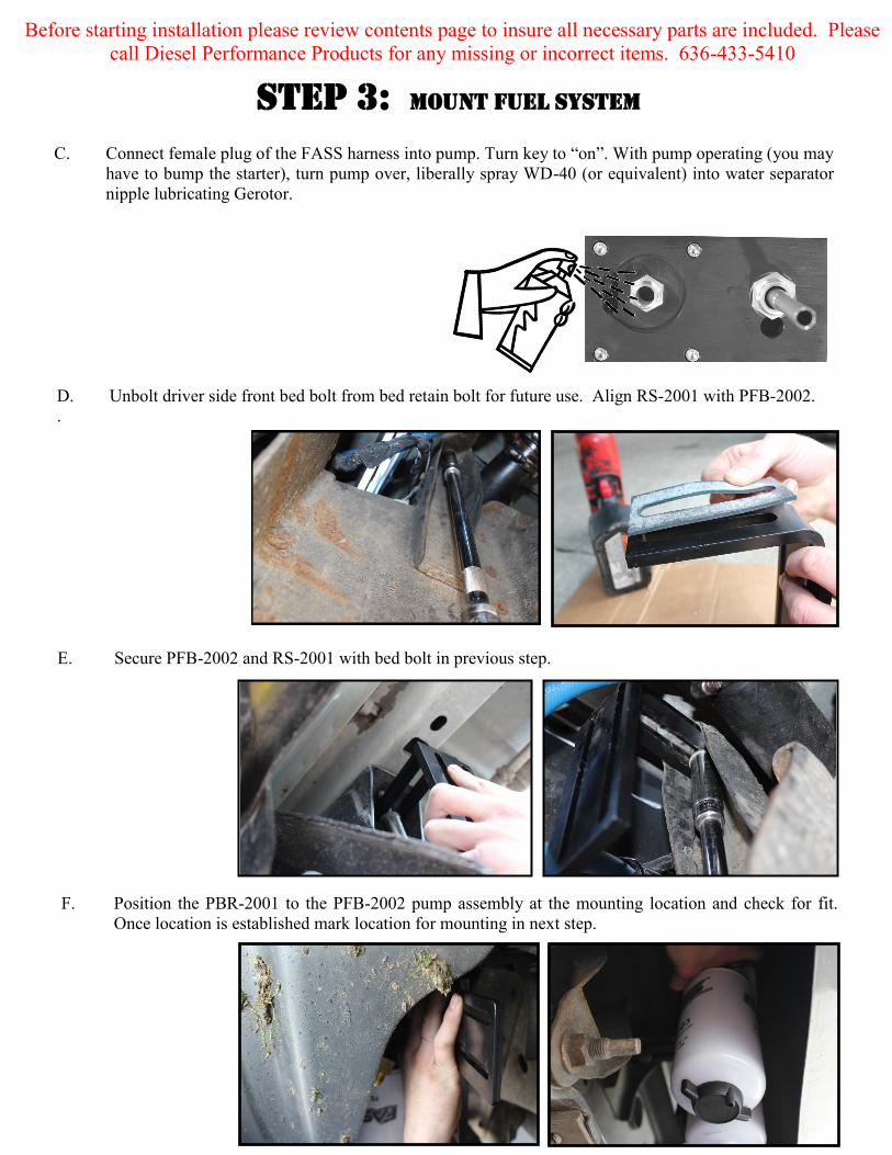
F. Position the PBR-2001 to the PFB-2002 pump assembly at the mounting location and check for fit.
Once location is established mark location for mounting in next step.
E. Secure PFB-2002 and RS-2001 with bed bolt in previous step.
C. Connect female plug of the FASS harness into pump. Turn key to “on”. With pump operating (you may
have to bump the starter), turn pump over, liberally spray WD-40 (or equivalent) into water separator
nipple lubricating Gerotor.
D. Unbolt driver side front bed bolt from bed retain bolt for future use. Align RS-2001 with PFB-2002.
.
Before starting installation please review contents page to insure all necessary parts are included. Please
call Diesel Performance Products for any missing or incorrect items. 636-433-5410

Step 3: Mount Fuel System
H. Once secure use 3-1 1/2 bolts and 3-WA-1001D spacers to mount the pump to the bracket.
G. Assemble the FASS pump bracket PBR-2001 using the RS-2002 spacer between PFB-2002 and PBR-
2001 bracket with 4-3/8 bolts, nuts, and washers. Note: Torque bolts not flange nut.
Before starting installation please review contents page to insure all necessary parts are included. Please
call Diesel Performance Products for any missing or incorrect items. 636-433-5410

Step 3: Mount Fuel System
I. Apply motor oil to gasket located on filters. Attach to system and
hand tighten.
Note: O-Ring must be put back on suction side of pump.
Failure to do so can result in priming issues, cavitation, or
pressure loses.
Fuel Filter –Install FF-3003 on
side of pump with draw tube in
the middle of the filter nipple.
Water Separator Filter –Install FS-1001 on water separator
nipple without the draw tube. Make sure to insert O-Ring
provided on nipple.
Before starting installation please review contents page to insure all necessary parts are included. Please
call Diesel Performance Products for any missing or incorrect items. 636-433-5410
E. Reattach the 3 bolts holding the fuel cooler to the mounting bracket.
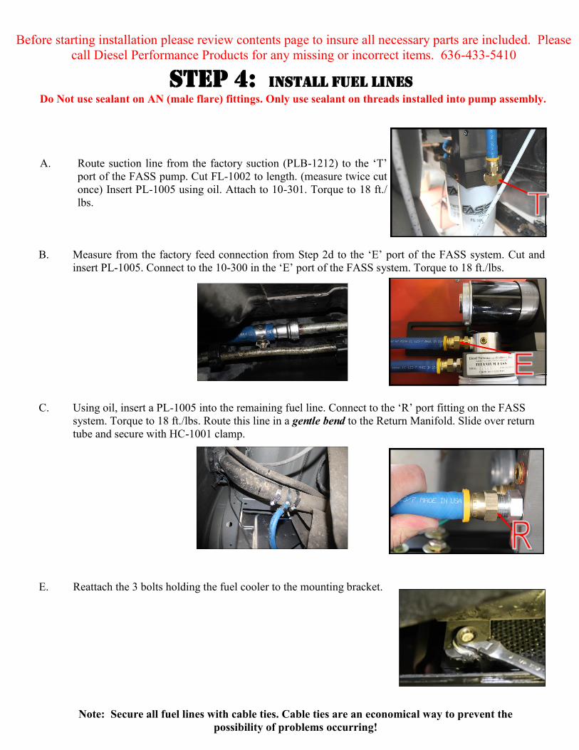
B. Measure from the factory feed connection from Step 2d to the ‘E’ port of the FASS system. Cut and
insert PL-1005. Connect to the 10-300 in the ‘E’ port of the FASS system. Torque to 18 ft./lbs.
C. Using oil, insert a PL-1005 into the remaining fuel line. Connect to the ‘R’ port fitting on the FASS
system. Torque to 18 ft./lbs. Route this line in a gentle bend to the Return Manifold. Slide over return
tube and secure with HC-1001 clamp.
Step 4: Install Fuel Lines
Do Not use sealant on AN (male flare) fittings. Only use sealant on threads installed into pump assembly.
A. Route suction line from the factory suction (PLB-1212) to the ‘T’
port of the FASS pump. Cut FL-1002 to length. (measure twice cut
once) Insert PL-1005 using oil. Attach to 10-301. Torque to 18 ft./
lbs.
Note: Secure all fuel lines with cable ties. Cable ties are an economical way to prevent the
possibility of problems occurring!
Before starting installation please review contents page to insure all necessary parts are included. Please
call Diesel Performance Products for any missing or incorrect items. 636-433-5410

Note: The Red Plastic Plugs located in the “H” ports can stay in place fuel will not flow
through these ports. Coolant can be plumbed into these ports to heat the fuel in the Winter
months.
To assist with priming your FASS pump crack the FF-3003. Put power to the FASS pump to
activate the pump. When the tone of the pump changes you can tighten up the fuel filter. If
you need a video of the priming process go to www.FASSride.com.
Step 5: Review Installation
Before starting installation please review contents page to insure all necessary parts are included. Please
call Diesel Performance Products for any missing or incorrect items. 636-433-5410

Step 5: Review Installation
Blow out any open lines/cover any open ports
Bolts and fasteners properly tightened?
Electrical harness and fuel lines secured and properly tightened? Reconnect the battery.
Has the system been primed?
1. Turn key to the ignition position, turning on the FASS pump for 15 sec..
2. Crank engine and allow to run for at least 1 minute.
Check for leaks.
Start the engine
Recheck all fluid and filter connections for leaks
This pump comes with a 1 Year Manufacturer’s Warranty based on the date it has been manufactured.
To receive your extended Lifetime Warranty, you have 30 days from date of purchase to send the
com-pleted warranty information along with a copy of the purchase receipt in to Diesel Performance
Prod-ucts, Inc. Att: Warranty 16234 Hwy O Marthasville, MO 63357
Before starting installation please review contents page to insure all necessary parts are included. Please
call Diesel Performance Products for any missing or incorrect items. 636-433-5410

LIMITATION OF Lifetime WARRANTY
Disclaimer: To help insure you receive the proper system and customer support at the local level, FASS has a VIP and Authorized Dealer network representing FASS products. This is one reason you must purchase through a dealer to comply with our warranty policies. If you do not, there is no warranty! We recommend you go to www.FASSride.com, click “Find a Dealer”, put in their ZIP code, select the type of dealer, and see if the company you purchased from is listed. If they are not, put their phone number in the field below the ZIP code field to see if they are listed. Below these two fields is a list of “Terminated/Unauthorized” dealers. You may want to review this list. If the company is not listed or is on the “Terminated/Unauthorized” list, we suggest you return the product immediately to that dealer and call FASS. We’ll recom-mend you to the nearest dealer.
Diesel Performance Products, Inc. (hereafter “SELLER”) gives Limited Warranty as to description, quality, merchantabil-
ity, fitness for any product’s purpose, productiveness, or any other matter of SELLER’S product sold herewith. The SELL-
ER shall be in no way responsible for the product’s open use and service and the BUYER hereby waives all rights other
than those expressly written herein. This Warranty shall not be extended or varied except by a written instrument signed by
SELLER and BUYER.
When MANUFACTURER receives the “ORIGINAL” PRODUCT REGISTRATION form with a copy of the “BILL
OF SALE/SALES RECEIPT” within 30 days of the sale, then the following applies! The Warranty will then and
only then be validated to that of which typically accompanies your unit for your specific application from the date of sale or
for recommended service life and limited solely to the original purchaser and/or vehicle and parts contained within the
product’s kit. This warranty does not cover normal wear on consumable items such as but not limited to filters, fuel line,
wire harness & etc. The warranty does not cover seized gears due to lack of filtration. Warranty is voided if used with other
than diesel fuel. Returned items will arrive prepaid to the place of purchase. Diesel Performance Products, Inc. will repair,
without cost, any product found to be defective during the warranty period; parts only, or at its option, will replace such
products in exchange for the product. Repair or replacements are warranted for the remainder of the original warranty peri-
od. All Warranty claims are subject to approval by Diesel Performance Products, Inc.
A Return Material Authorization (RMA) number must be obtained before any product is to be returned to Diesel
Performance Products, Inc. for warranty consideration, repair or product return. Requests for product returns
must be offset by an equal value order. Return parts must be completed and in resalable condition. No returns after 30 days.
The following information is required to obtain a RMA number before returning product:
Your Name, Address, and Phone Number’s Model and Serial Number (Not Motor Number) Example: Model HD Series, Serial: 00125966 VIN Number of Vehicle Date of Purchase Nature of Problem
RMA and Product Serial Number must be on all paperwork and correspondence. Failure to obtain the required information
or paperwork will result in $25.00/item penalty and delay or denial of any warranty claim.
Under no circumstances shall the SELLER and/or MANUFACTURER be liable for any labor charged or travel time in-
curred in diagnosis for defects, removal, or reinstallation of this product, or any other contingent expenses.
Under no circumstances shall the SELLER and/or MANUFACTURER be liable for any damage or expenses insured by
reason of the use or sale of any such equipment. This warranty does not apply to products which Diesel Performance Prod-
ucts, Inc. has determined to have been misused or abused, improperly maintained by the user, or where the malfunction or
defect can be attributed to the use of non-genuine Diesel Performance Products, Inc. parts.
IN THE EVENT THAT THE BUYER DOES NOT AGREE WITH THIS AGREEMENT: THE BUYER MAY PROMPLY
RETURN THIS PRODUCT, IN A NEW AND UNUSED CONDITION, WITH A DATED PROOF OF PURCHASE, TO
THE PLACE OF PURCHASE WITHIN THIRTY (30) DAYS FROM DATE OF PURCHASE FOR A FULL REFUND
LESS SHIPPING.
THE INSTALLATION OF THIS PRODUCT INDICATES THAT THE BUYER HAS READ AND UNDER-
STANDS THIS AGREEMENT AND ACCEPTS ITS TERMS AND CONDITIONS.
Technical Support:
Diesel Performance Products, Inc.
16234 State Hwy O
Marthasville, MO 63357
636-433-5410

Notes

Notes