Embed Size (px)
Citation preview
King Air 350 Developed for Training Purposes 3-1October 2001
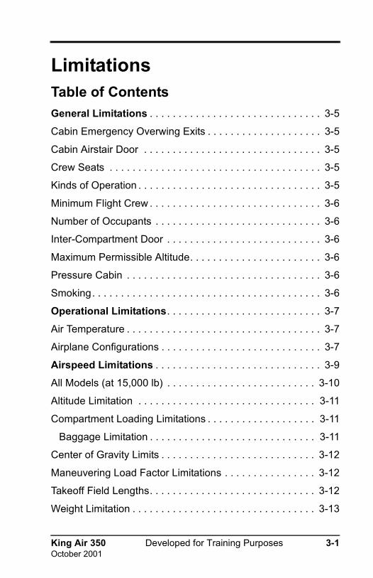
LimitationsTable of ContentsGeneral Limitations . . . . . . . . . . . . . . . . . . . . . . . . . . . . . . 3-5
Cabin Emergency Overwing Exits . . . . . . . . . . . . . . . . . . . . 3-5
Cabin Airstair Door . . . . . . . . . . . . . . . . . . . . . . . . . . . . . . . 3-5
Crew Seats . . . . . . . . . . . . . . . . . . . . . . . . . . . . . . . . . . . . . 3-5
Kinds of Operation . . . . . . . . . . . . . . . . . . . . . . . . . . . . . . . . 3-5
Minimum Flight Crew . . . . . . . . . . . . . . . . . . . . . . . . . . . . . . 3-6
Number of Occupants . . . . . . . . . . . . . . . . . . . . . . . . . . . . . 3-6
Inter-Compartment Door . . . . . . . . . . . . . . . . . . . . . . . . . . . 3-6
Maximum Permissible Altitude. . . . . . . . . . . . . . . . . . . . . . . 3-6
Pressure Cabin . . . . . . . . . . . . . . . . . . . . . . . . . . . . . . . . . . 3-6
Smoking. . . . . . . . . . . . . . . . . . . . . . . . . . . . . . . . . . . . . . . . 3-6
Operational Limitations. . . . . . . . . . . . . . . . . . . . . . . . . . . 3-7
Air Temperature . . . . . . . . . . . . . . . . . . . . . . . . . . . . . . . . . . 3-7
Airplane Configurations . . . . . . . . . . . . . . . . . . . . . . . . . . . . 3-7
Airspeed Limitations . . . . . . . . . . . . . . . . . . . . . . . . . . . . . 3-9
All Models (at 15,000 lb) . . . . . . . . . . . . . . . . . . . . . . . . . . 3-10
Altitude Limitation . . . . . . . . . . . . . . . . . . . . . . . . . . . . . . . 3-11
Compartment Loading Limitations . . . . . . . . . . . . . . . . . . . 3-11
Baggage Limitation . . . . . . . . . . . . . . . . . . . . . . . . . . . . . 3-11
Center of Gravity Limits . . . . . . . . . . . . . . . . . . . . . . . . . . . 3-12
Maneuvering Load Factor Limitations . . . . . . . . . . . . . . . . 3-12
Takeoff Field Lengths. . . . . . . . . . . . . . . . . . . . . . . . . . . . . 3-12
Weight Limitation . . . . . . . . . . . . . . . . . . . . . . . . . . . . . . . . 3-13

3-2 Developed for Training Purposes King Air 350October 2001
CAE SimuFlite
Wind Component . . . . . . . . . . . . . . . . . . . . . . . . . . . . . . . . 3-13
Maximum Demonstrated Crosswind . . . . . . . . . . . . . . . . . 3-13
Systems Limitations . . . . . . . . . . . . . . . . . . . . . . . . . . . . 3-15
Avionics Systems. . . . . . . . . . . . . . . . . . . . . . . . . . . . . . . . 3-15
FAR Part 91 Operations . . . . . . . . . . . . . . . . . . . . . . . . . 3-15
FAR Part 135 Operations . . . . . . . . . . . . . . . . . . . . . . . . 3-15
Electrical Systems . . . . . . . . . . . . . . . . . . . . . . . . . . . . . . . 3-15
External Power Unit . . . . . . . . . . . . . . . . . . . . . . . . . . . . 3-15
Generator Limits . . . . . . . . . . . . . . . . . . . . . . . . . . . . . . . 3-15
Starter Limitations . . . . . . . . . . . . . . . . . . . . . . . . . . . . . . . 3-16
Flight Controls . . . . . . . . . . . . . . . . . . . . . . . . . . . . . . . . . . 3-16
Flaps . . . . . . . . . . . . . . . . . . . . . . . . . . . . . . . . . . . . . . . . 3-16
Rudder Boost . . . . . . . . . . . . . . . . . . . . . . . . . . . . . . . . . 3-16
Fuel System. . . . . . . . . . . . . . . . . . . . . . . . . . . . . . . . . . . . 3-16
Minimum Temperature Limits . . . . . . . . . . . . . . . . . . . . . 3-16
Anti-Icing Additive . . . . . . . . . . . . . . . . . . . . . . . . . . . . . . 3-17
Fuel Biocide Additive . . . . . . . . . . . . . . . . . . . . . . . . . . . 3-17
Approved Engine Fuel . . . . . . . . . . . . . . . . . . . . . . . . . . 3-17
Emergency Engine Fuels . . . . . . . . . . . . . . . . . . . . . . . . 3-17
Limitations on the Use of Aviation Gasoline . . . . . . . . . . 3-18
Fuel Management . . . . . . . . . . . . . . . . . . . . . . . . . . . . . . 3-18
Capacities . . . . . . . . . . . . . . . . . . . . . . . . . . . . . . . . . . . . 3-18
Ice and Rain Protection Systems. . . . . . . . . . . . . . . . . . . . 3-19
Landing Gear Limitations. . . . . . . . . . . . . . . . . . . . . . . . . . 3-19
Powerplant Limitations. . . . . . . . . . . . . . . . . . . . . . . . . . . . 3-19
Engine Operating Limits . . . . . . . . . . . . . . . . . . . . . . . . . . 3-19

King Air 350 Developed for Training Purposes 3-3October 2001
Limitations
Oil Specifications . . . . . . . . . . . . . . . . . . . . . . . . . . . . . . . . 3-21
Oxygen . . . . . . . . . . . . . . . . . . . . . . . . . . . . . . . . . . . . . . . 3-21
Propeller . . . . . . . . . . . . . . . . . . . . . . . . . . . . . . . . . . . . . . 3-21
Manufacturer. . . . . . . . . . . . . . . . . . . . . . . . . . . . . . . . . . 3-21
Propeller Blade Angles . . . . . . . . . . . . . . . . . . . . . . . . . . 3-21
Propeller Rotational Speed Limits. . . . . . . . . . . . . . . . . . 3-21
Propeller Rotational Overspeed Limits . . . . . . . . . . . . . . 3-22
Propeller Autofeather . . . . . . . . . . . . . . . . . . . . . . . . . . . 3-22
3-4 Developed for Training Purposes King Air 350October 2001
CAE SimuFlite

King Air 350 Developed for Training Purposes 3-5October 2001
Limitations
General LimitationsCabin Emergency Overwing Exits
Do not open or check security by moving door handle whileaircraft is pressurized and/or in flight.
Handle is in locked position when arm is around the plunger.
The lock-levers must be in the up or unlocked position priorto flight.
See AFM Supplements section for limitations with Airstairdoor removed.
Cabin Airstair DoorDo not open or check door security by moving door handlewhile aircraft is pressurized and/or in flight.
Handle is in the locked position when the arm is around theplunger.
Only a crewmember should close and lock the door.
Only one person on the Airstair door at a time.
Crew SeatsBoth crew seats shall be locked in position during takeoffand landing.
Kinds of Operation
WARNING: Unless authorized by applicable Departmentof Transportation regulations, do not carry hazardousmaterial anywhere in the aircraft.
The King Air is approved for the following operations whenrequired equipment is installed and operational. Refer to Kindsof Operations Equipment List in the Aircraft Operating Manual.

3-6 Developed for Training Purposes King Air 350February 2006
CAE SimuFlite
VFR Day
VFR Night
IFR Day
IFR Night
Known Icing Conditions
Minimum Flight CrewMinimum flight crew is one pilot.
Number of OccupantsThe total number of persons carried shall not exceed 15 orthat for which approved seating accommodation is provided.
Inter-Compartment DoorWhen a door is provided between the crew and passengercompartments, it shall be secured in the open position dur-ing takeoff and landing.
Maximum Permissible AltitudeMaximum permissible operating altitude is 35,000 ft.
Pressure CabinThe cabin shall not be pressurized during takeoff and land-ing. Maximum pressure differential for normal operation is6.6 PSI.
SmokingSmoking is not permitted when No Smoking/Fasten SeatBelt sign is illuminated.
Smoking is prohibited when oxygen is in use.

King Air 350 Developed for Training Purposes 3-7October 2001
Limitations
Operational LimitationsAir TemperatureSea Level to 25,000 ft Pressure Altitude . . . . . . . . . ISA + 37ºC
Above 25,000 ft Pressure Altitude . . . . . . . . . . . . . . ISA + 31ºC
Airplane ConfigurationsThe airplane configurations should as stated in AFM section 6.
CAUTION: For turbulent air penetration, use an airspeedof 170 knots. Avoid over-action on power levers. Turn offautopilot altitude hold. Keep wings level, maintain attitudeand avoid use of trim. Do not chase altitude and altitude.Penetration should be at an altitude which provides ade-quate maneuvering margins when severe turbulence isencountered.

3-8 Developed for Training Purposes King Air 350October 2001
CAE SimuFlite

King Air 350 Developed for Training Purposes 3-9October 2001
Limitations
Airspeed LimitationsSPEED KCAS KIAS REMARKS
Maneuvering Speed VA 182 184
Do not make full or abrupt control move-ments above this speed.
Maximum Flap Extension/Extended Speed (VFE) ApproachFull Down
200155
202158
Do not extend flaps or operate with flaps extended above these speeds.
Maximum Landing Gear Operating Speed (VLO)ExtensionRetraction
182164
184166
Do not extend or retract landing gear above these speeds.
Maximum Landing Gear Extended Speed (VLE) 182 184
Do not exceed this speed with landing gear extended.
Air Minimum Control Speed (VMCA)Propeller Feathered
Flaps UpFlaps Approach
9694
9493
These are the lowest air-speeds at which the air-plane is directionally controllable when one engine suddenly becomes inoperative, with autofeather armed, and the other engine at takeoff power.
Maximum Operating Speed (VMO)Sea Level to 21,000 ft21,000 ft to 35,000 ft
260260-192*
263263-194*
These speeds may not be deliberately exceeded in any flight regime.Red pointer reflects VMO/MMO limits.
*0.58 Mach
Table 3-A; Speed Limitations

3-10 Developed for Training Purposes King Air 350October 2001
CAE SimuFlite
All Models (at 15,000 lb)Two-Engine Best Angle-of-Climb (VX) . . . . . . . . . . . . 125 KIAS
Two-Engine Best Rate-of-Climb (VY). . . . . . . . . . . . . 140 KIAS
Cruise Climb:
Sea Level to 10,000 ft . . . . . . . . . . . . . . . . . . . . . . 170 KIAS
10,000 to 15,000 ft . . . . . . . . . . . . . . . . . . . . . . . . 160 KIAS
15,000 to 20,000 ft . . . . . . . . . . . . . . . . . . . . . . . . 150 KIAS
20,000 to 25,000 ft . . . . . . . . . . . . . . . . . . . . . . . . 140 KIAS
25,000 to 30,000 ft . . . . . . . . . . . . . . . . . . . . . . . . 130 KIAS
30,000 to 35,000 ft . . . . . . . . . . . . . . . . . . . . . . . . 120 KIAS
Maneuvering Speed (VA) . . . . . . . . . . . . . . . . . . . 184 KIAS
Turbulent Air Penetration . . . . . . . . . . . . . . . . . . . 170 KIAS
Maximum Airspeed for Effective
Windshield Anti-Icing . . . . . . . . . . . . . . . . . . . . . . . . . 226 KIAS
Intentional One-Engine Inoperative Speed (VSSE) . . .110 KIAS
Air Minimum Control Speed (VMCA):
Flaps Up . . . . . . . . . . . . . . . . . . . . . . . . . . . . . . . . . 94 KIAS
Flaps Approach . . . . . . . . . . . . . . . . . . . . . . . . . . . 93 KIAS
King Air 350 Developed for Training Purposes 3-11October 2001
Limitations
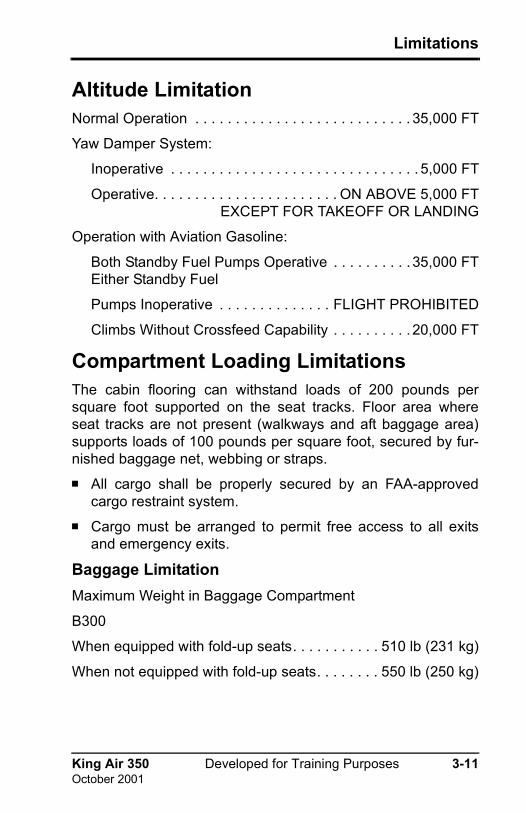
Altitude LimitationNormal Operation . . . . . . . . . . . . . . . . . . . . . . . . . . . 35,000 FT
Yaw Damper System:
Inoperative . . . . . . . . . . . . . . . . . . . . . . . . . . . . . . . 5,000 FT
Operative. . . . . . . . . . . . . . . . . . . . . . . ON ABOVE 5,000 FTEXCEPT FOR TAKEOFF OR LANDING
Operation with Aviation Gasoline:
Both Standby Fuel Pumps Operative . . . . . . . . . . 35,000 FTEither Standby Fuel
Pumps Inoperative . . . . . . . . . . . . . . FLIGHT PROHIBITED
Climbs Without Crossfeed Capability . . . . . . . . . . 20,000 FT
Compartment Loading LimitationsThe cabin flooring can withstand loads of 200 pounds persquare foot supported on the seat tracks. Floor area whereseat tracks are not present (walkways and aft baggage area)supports loads of 100 pounds per square foot, secured by fur-nished baggage net, webbing or straps.
All cargo shall be properly secured by an FAA-approvedcargo restraint system.
Cargo must be arranged to permit free access to all exitsand emergency exits.
Baggage LimitationMaximum Weight in Baggage Compartment
B300
When equipped with fold-up seats. . . . . . . . . . . 510 lb (231 kg)
When not equipped with fold-up seats. . . . . . . . 550 lb (250 kg)

3-12 Developed for Training Purposes King Air 350October 2001
CAE SimuFlite
B300C
When equipped with toiletand fold-up seat . . . . . . . . . . . . . . . . . . . . . . . . . 510 lb (231 kg)
When equipped with toilet . . . . . . . . . . . . . . . . . 550 lb (250 kg)
Center of Gravity LimitsThe reference datum is located 83.5 inches forward of thecenter of the front jack point.
Aft Limit - 208 inches aft of datum at all weights.
Forward at 11,800 lb - 191.4 inches aft of datum with straightline variation to 199.4 inches aft of datum at 15,000 lb.
Forward at 11,800 lb or less - 191.4 inches aft of datum.
Maneuvering Load Factor LimitationsThe Beechcraft Super King Air B300 and B300C normal cate-gory airplane. Aerobatic maneuvers, including spins areprohibited.
FLAPS UP
Positive . . . . . . . . . . . . . . . . . . . . . . . . . . . . . . . . . . . . .3.1 G
Negative . . . . . . . . . . . . . . . . . . . . . . . . . . . . . . . . . . .1.24 G
FLAPS DOWN
Positive . . . . . . . . . . . . . . . . . . . . . . . . . . . . . . . . . . . . . . 2 G
Negative . . . . . . . . . . . . . . . . . . . . . . . . . . . . . . . . . . . . . 0 G
Takeoff Field LengthsThe takeoff weight shall not exceed the maximum permittedby field length considerations as calculated by the methoddescribed in section 5 of the AFM. Consider the followingfactors determining take field length: takeoff flap setting,anti-icing setting, airport altitude, runway to be used, runwayslope, wind component and air temperature.

King Air 350 Developed for Training Purposes 3-13May 2005
Limitations
Weight LimitationMaximum Ramp. . . . . . . . . . . . . . . . . . . . . . . . . . . . . 15,100 LB
Maximum Takeoff. . . . . . . . . . . . . . . . . . . . . . . . . . . . 15,000 LB
Except for the following limitations:- Takeoff Climb Requirements- Tire Speed- Takeoff Field Length- Brake Energy
For FAR Operations:- Takeoff Flight Path Requirements to 1,500 ft AGL- Service Ceiling - One Engine Inoperative
Maximum landing. . . . . . . . . . . . . . . . . . . . . . . . . . . . 15,000 LB
Except for the following limitations:- Maximum Landing Weight to Achieve Climb Requirements- Normal Landing Distance - Flaps Down
Maximum Zero Fuel . . . . . . . . . . . . . . . . . . . . . . . . . . 12,500 LB
Wind ComponentThe maximum tailwind component for takeoff and landing is10 kt.
Maximum Demonstrated CrosswindThe maximum crosswind component in which the aircrafthas been demonstrated to be satisfactory for takeoff andlanding is 20 kt.

3-14 Developed for Training Purposes King Air 350October 2001
CAE SimuFlite

King Air 350 Developed for Training Purposes 3-15October 2001
Limitations
System LimitationsAvionics SystemsFAR Part 91 Operations
Refer to the applicable FAA-approved Flight Manual Supple-ment in the AFM Supplements section.
FAR Part 135 OperationsRefer to the applicable FAA-approved Flight Manual Supple-ment in the AFM Supplements Section for your particularautopilot installation except for Minimum Altitude which isestablished by FAR Part 135.93.
Electrical SystemsExternal Power Unit
28 to 28.4V DC output
300 continuous
1,000 amp surge
Generator LimitsMaximum Sustained Generator Load is limited as follow:
In-flight Sea Level to 34,000 ft Altitude . . . . . . . . . . . . 100%
In-flight Above 34,000 ft Altitude . . . . . . . . . . . . . . . . . . 95%
Ground Operation:
N1 Maximum Generator Load
62% to 70% 75%
70% to 100% 100%
Table 3-B; Generator Ground Operation Limits

3-16 Developed for Training Purposes King Air 350October 2001
CAE SimuFlite
Starter LimitationsStandard Start Cycle:
30 seconds ON, 5 minutes OFF30 seconds ON, 5 minutes OFF30 seconds ON, 30 minutes OFF.
Flight ControlsFlapsFlaps movement is limited to three positions:
UPAPPROACHDOWN
Rudder BoostThe rudder boost must be operational for all phases of flight.
Fuel System
CAUTION: Anti-icing additive must be properly blendedwith the fuel to avoid deterioration of the fuel cells. Theadditive concentration by volume shaII be a minimum of0.050% and a maximum of 0.150%.
Minimum Temperature Limits
Table 3-C; Fuel Minimum Temperature Limits
Commercial Grades Military Grades
Fuel Temperature Fuel Temperature
Jet A -40ºC JP-4 -58ºC
Jet A-1 -47ºC JP-5 -46ºC
Jet B -50ºC JP-8 -50ºC

King Air 350 Developed for Training Purposes 3-17October 2001
Limitations
Anti-Icing AdditiveAnti-icing additive conforming to Specification MIL-I-27686is the only approved fuel anti-icing additive. Engine oil is used to heat fuel entering the fuel control unit.Since no temperature measurement is available for the fuelat this point, It must be assumed to be the same as OAT. Ifknown or forecast temperatures are below minimum temper-ature limits Table 3-C, anti-icing additive per MIL-I-27686must be mixed with the fuel at refueling to ensure safeoperation.
Fuel Biocide AdditiveFuel biocide-fungicide BIOBOR JF in concentrations of 135PPM or 270 PPM, may be used in the fuel, BIOBOR JF may beused as the only fuel additive or it may be used with the anti-icing additive conforming to MIL-I-27686 specifications. Usedtogether, the additives have no detrimental effect on the fuelsystem components. Refer to the appropriate maintenance manual for appropriateconcentrations and for procedures for adding additives to thefuel.
Approved Engine FuelCommercial Grades. . . . . . . . . . . . . . . . . . Jet A, Jet A-1, Jet B
Military Grades. . . . . . . . . . . . . . . . . . . . . . . . . JP-4, JP-5, JP-8
Emergency Engine FuelsCommercial Aviation Gasoline Grades . . . . . . . . . . . . . 80 RED, 91/96, 100 GREEN
100 LL BLUE*, 115/145 PURPLE
Military AviationGasoline Grades . . . . . . . . . . . . . 80/87 RED,100/130 GREEN
115/145 PURPLE* In some countries, this fuel is colored Green and designated
“100L”.

3-18 Developed for Training Purposes King Air 350October 2001
CAE SimuFlite
Limitations on the Use of Aviation GasolineOperation is limited to 150 hours between engine overhauls.Both standby fuel pumps must be capable of operation.Crossfeed capability is required for flight above 20,000 ftpressure altitude (FL200).
Fuel Management
WARNING: One operative standby fuel pump is requiredfor takeoff when using recommended engine fuels, but insuch cases, crossfeed of fuel will not be available from theside of the inoperative standby fuel pump.
Do not put any fuel into the auxiliary tanks unless the maintanks are full.
Maximum allowable fuel imbalance for wing fuel systems is300 pounds.
Do not take off if fuel quantity gages indicate in the yellowarc.
Crossfeeding of fuel is permitted only when one engine isinoperative.
Operation with low fuel pressure is limited to 10 hoursbefore overhaul of the engine driven pump (windmilling timeis not counted against the time).
CapacitiesMaximum Usable Fuel Quantity. . . . . 3,611 LB (539 GALLON)
Each Main Fuel Tank system. . . . . . . 1,273 LB (190 GALLON)
Each Auxiliary Fuel Tank . . . . . . . . . . . 533 LB (79.5 GALLON)

King Air 350 Developed for Training Purposes 3-19October 2001
Limitations
Ice and Rain Protection SystemsSustained Icing Condition Airspeed. . . . . 140 KNOT MINIMUM
Windshield Icing Condition . . . . . . . . . . 226 KNOT MAXIMUM
Prior to landing approach, cycle the deicing boots to shed anyaccumulated ice.
Landing Gear LimitationsLanding gear cycles (1 up and 1 down) are limited to one every5 minutes for a total of 6 cycles, followed by a 15-minute cool-down period.
Powerplant LimitationsNumber of Engines – two
Engine Manufacturer – Pratt & Whitney of Canada(Longueuil, Quebec, Canada).
Engine Model Number PT6A-60A.
Do not lift power levers in flight
Engine Operating LimitsThe following limitations presented in Table 3-D shall beobserved. Each column presents limitations. The limits rep-resented do not occur simultaneously. Refer to Pratt &Whitney Engine Maintenance Manual for specific actionsrequired if limits are exceeded.

3-20 Developed for Training Purposes King Air 350May 2005
CAE SimuFlite
1 Torque limit applies within range of 1,000 - 1,700 propeller rpm (N2). Below 1000 propeller rpm, torque is limited to 62%.
2 Normal oil pressure is 90 to 135 PSIG at gas generator speeds above 72%. With engine torque below 62%, minimum oil pressure is 60 PSIG at normal oil temperature (60º to 70º C). Oil pressures under 90 PSIG are undesirable. Under emergency con-ditions, to complete a flight, a lower oil pressure limit of 60 PSIG is permissible at reduced power level not to exceed 62% torque. Oil pressures below 60 PSIG are unsafe and require that either the engine be shut down or a landing be made at the nearest suitable airport, using the minimum power required to sustain flight. Fluctua-tion of plus or minus 10 PSI are acceptable.
3 A minimum oil temperature of 55ºC is recommended for fuel heater operation at take-off power.
4 Oil temperature limits are –40ºC and +110ºC. However, temperatures between 99º and 110ºC are limited to a maximum of 10 minutes.
5 This value is time-limited to 5 seconds.6 High ITT at ground idle may be corrected by reducing accessory load and/or Increas-
ing N1 rpm.7 Cruise torque values with altitude and temperature. 8 These values are time-limited to 20 seconds.9 To account for power setting accuracy and steady state flucuations, inadvertent propeller
RPM excursions up to 1735 RPM are time limited to 7 minutes.10 To account for power setting accuracy and steady state flucuations, inadvertent
torque excursions up to 102% is time limited to 7 minutes.
Table 3-D; Engine Operating Limits
Operating Condition
Torque(ft-lbs)1
Max ITT °C
Gas Generator RPM % N1
Prop RPM N2
Oil Pressure
(OSI)2Oil Temp
°C3, 4
Starting – 10005 – – 0 to 200 -40 (min)
Idle – 7506 62 (min) 1050 (min) 60 (min) -40 to +110
Takeoff 100 10 820 104 17009 90 to 135 0 to 110
Max Cont 100 10 820 104 17009 90 to 135 0 to 110
Cruise Climb Notes7, 10 785 104 17009 90 to 135 0 to 110
Max Cruise Notes7, 10 820 104 17009 90 to 135 0 to 110
Max Reverse – 760 – 1650 90 to 135 0 to 99
Transient 1568 8508 104 18708 200 0 to 110
King Air 350 Developed for Training Purposes 3-21October 2001
Limitations
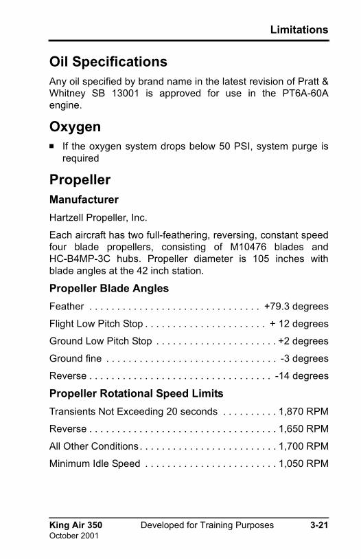
Oil SpecificationsAny oil specified by brand name in the latest revision of Pratt &Whitney SB 13001 is approved for use in the PT6A-60Aengine.
OxygenIf the oxygen system drops below 50 PSI, system purge isrequired
PropellerManufacturerHartzell Propeller, Inc.
Each aircraft has two full-feathering, reversing, constant speedfour blade propellers, consisting of M10476 blades andHC-B4MP-3C hubs. Propeller diameter is 105 inches withblade angles at the 42 inch station.
Propeller Blade AnglesFeather . . . . . . . . . . . . . . . . . . . . . . . . . . . . . . . +79.3 degrees
Flight Low Pitch Stop . . . . . . . . . . . . . . . . . . . . . . + 12 degrees
Ground Low Pitch Stop . . . . . . . . . . . . . . . . . . . . . . +2 degrees
Ground fine . . . . . . . . . . . . . . . . . . . . . . . . . . . . . . . -3 degrees
Reverse . . . . . . . . . . . . . . . . . . . . . . . . . . . . . . . . . -14 degrees
Propeller Rotational Speed LimitsTransients Not Exceeding 20 seconds . . . . . . . . . . 1,870 RPM
Reverse . . . . . . . . . . . . . . . . . . . . . . . . . . . . . . . . . . 1,650 RPM
All Other Conditions. . . . . . . . . . . . . . . . . . . . . . . . . 1,700 RPM
Minimum Idle Speed . . . . . . . . . . . . . . . . . . . . . . . . 1,050 RPM

3-22 Developed for Training Purposes King Air 350October 2001
CAE SimuFlite
Propeller Rotational Overspeed LimitsSustained propeller overspeeds faster that 1,700 rpm indicatefailure of the primary governor. Flight may be continued at pro-peller overspeeds up to 1,768 rpm provided torque is limited to95%. Sustained overspeeds faster than 1,768 rpm are notapproved.
Propeller AutofeatherMust be operational for all flights and armed for takeoff, climband approach.