Embed Size (px)
Citation preview

TC APPROVED BHT-407-FM-1
19 FEB 2007—Rev. 5———1-1
Section 1LIMITATIONS
1
TABLE OF CONTENTS
Paragraph Page
Subject Number Number
Introduction ............................................................................................ 1-1 ........... 1-3
Basis of Certification ............................................................................. 1-2 ........... 1-3
Types of Operation ................................................................................ 1-3 ........... 1-3
Passengers......................................................................................... 1-3-A ....... 1-3
Cargo................................................................................................... 1-3-B ....... 1-3
Flight Crew ............................................................................................. 1-4 ........... 1-3
Configuration ......................................................................................... 1-5 ........... 1-3
Required Equipment.......................................................................... 1-5-A ....... 1-3
Optional Equipment.......................................................................... 1-5-B ....... 1-4
Doors Removed ................................................................................ 1-5-C ....... 1-4
Weight and Center of Gravity ............................................................... 1-6 ........... 1-4
Weight ................................................................................................. 1-6-A ....... 1-4
Center of Gravity................................................................................ 1-6-B ....... 1-4
Airspeed.................................................................................................. 1-7 ........... 1-4
Altitude.................................................................................................... 1-8 ........... 1-5
Maneuvering........................................................................................... 1-9 ........... 1-5
Prohibited Maneuvers ....................................................................... 1-9-A ....... 1-5
Climb And Descent ............................................................................ 1-9-B ....... 1-5
Slope Landing .................................................................................... 1-9-C ....... 1-5
Not Used ................................................................................................. 1-10 ......... 1-5
Ambient Temperatures.......................................................................... 1-11 ......... 1-5
Electrical ................................................................................................. 1-12 ......... 1-5
Generator............................................................................................ 1-12-A ..... 1-5
Starter ................................................................................................. 1-12-B ..... 1-5
Power Plant ............................................................................................ 1-13 ......... 1-5
Gas Producer RPM (NG) .................................................................... 1-13-A ..... 1-6
Power Turbine RPM (NP) ................................................................... 1-13-B ..... 1-6
Measured Gas Temperature (MGT) .................................................. 1-13-C ..... 1-6
Engine Torque.................................................................................... 1-13-D ..... 1-6
Fuel Pressure ..................................................................................... 1-13-E ..... 1-6
Engine Oil Pressure........................................................................... 1-13-F...... 1-6
Engine Oil Temperature .................................................................... 1-13-G..... 1-7
Transmission.......................................................................................... 1-14 ......... 1-7
Transmission Oil Pressure ............................................................... 1-14-A ..... 1-7
Transmission Oil Temperature ......................................................... 1-14-B ..... 1-7
Rotor ....................................................................................................... 1-15 ......... 1-7

BHT-407-FM-1 TC APPROVED
1-2———Rev. 5—19 FEB 2007
TABLE OF CONTENTS (CONT)
Paragraph Page
Subject Number Number
Rotor RPM — Power ON ................................................................... 1-15-A..... 1-7
Rotor RPM — Power OFF.................................................................. 1-15-B..... 1-7
Hydraulic ................................................................................................ 1-16......... 1-7
Fuel and Oil ............................................................................................ 1-17......... 1-7
Fuel ..................................................................................................... 1-17-A..... 1-7
Oil ........................................................................................................ 1-17-B..... 1-8
Rotor Brake ............................................................................................ 1-18......... 1-8
Not Used................................................................................................. 1-19......... 1-8
Instrument Markings and Placards ...................................................... 1-20......... 1-8
LIST OF FIGURES
Figure Page
Subject Number Number
Gross Weight Longitudinal Center of Gravity Limits ......................... 1-1........... 1-9
Gross Weight Lateral Center of Gravity Limits................................... 1-2........... 1-11
Placards and Decals.............................................................................. 1-3........... 1-13
Ambient Air Temperature Limitations ................................................. 1-4........... 1-16
Instrument Markings ............................................................................. 1-5........... 1-17
TC APPROVED BHT-407-FM-1
19 FEB 2007—Rev. 5———1-3
Section 1LIMITATIONS
1
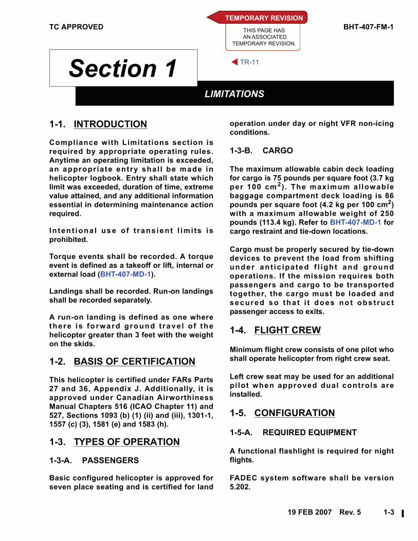
1-1. INTRODUCTION
Compliance with Limitations section is
required by appropriate operating rules.
Anytime an operating limitation is exceeded,
an appropr iate entry shal l be made in
helicopter logbook. Entry shall state which
limit was exceeded, duration of time, extreme
value attained, and any additional information
essential in determining maintenance action
required.
In ten t iona l use o f t rans ient l imi ts is
prohibited.
Torque events shall be recorded. A torque
event is defined as a takeoff or lift, internal or
external load (BHT-407-MD-1).
Landings shall be recorded. Run-on landings
shall be recorded separately.
A run-on landing is defined as one where
there is fo rward ground t rave l o f the
helicopter greater than 3 feet with the weight
on the skids.
1-2. BASIS OF CERTIFICATION
This helicopter is certified under FARs Parts
27 and 36, Appendix J. Additionally, it is
approved under Canadian Airworthiness
Manual Chapters 516 (ICAO Chapter 11) and
527, Sections 1093 (b) (1) (ii) and (iii), 1301-1,
1557 (c) (3), 1581 (e) and 1583 (h).
1-3. TYPES OF OPERATION
1-3-A. PASSENGERS
Basic configured helicopter is approved for
seven place seating and is certified for land
operation under day or night VFR non-icing
conditions.
1-3-B. CARGO
The maximum allowable cabin deck loading
for cargo is 75 pounds per square foot (3.7 kg
per 100 cm2 ) . The maximum al lowable
baggage compartment deck loading is 86
pounds per square foot (4.2 kg per 100 cm2)
with a maximum allowable weight of 250
pounds (113.4 kg). Refer to BHT-407-MD-1 for
cargo restraint and tie-down locations.
Cargo must be properly secured by tie-down
devices to prevent the load from shifting
under ant ic ipated f l igh t and g round
operations. If the mission requires both
passengers and cargo to be transported
together, the cargo must be loaded and
secured so tha t i t does no t obs t ruct
passenger access to exits.
1-4. FLIGHT CREW
Minimum flight crew consists of one pilot who
shall operate helicopter from right crew seat.
Left crew seat may be used for an additional
pi lot when approved dual controls are
installed.
1-5. CONFIGURATION
1-5-A. REQUIRED EQUIPMENT
A functional flashlight is required for night
flights.
FADEC system software shall be version
5.202.
TEMPORARY REVISION
THIS PAGE HAS
AN ASSOCIATED
TEMPORARY REVISION.
TR-11

BHT-407-FM-1 TC APPROVED
1-4———Rev. 7—30 JUL 2008
1-5-B. OPTIONAL EQUIPMENT
The snow deflector kit (BHT-407-FMS-4) shall
be ins ta l led when conduct ing f l ight
operations in falling and/or blowing snow.
Refer to appropr ia te f l ight manual
supplement (s ) (FMS) for addi t iona l
limitations, procedures, and performance data
for optional equipment.
1-5-C. DOORS REMOVED
NOTE
Indicated altitude may be up to 100
feet lower than actual altitude with
crew door(s) removed.
Flight with any combination of doors removed
is approved. With litter door removed, left
passenger door shall be removed. Refer to
Airspeed limitations.
With door(s) removed, determine weight
change and adjust ballast if necessary. Refer
to Section 5.
NOTE
Al l unsecured i tems sha l l be
removed from cabin when any door
is removed.
1-6. WEIGHT AND CENTER OFGRAVITY
1-6-A. WEIGHT
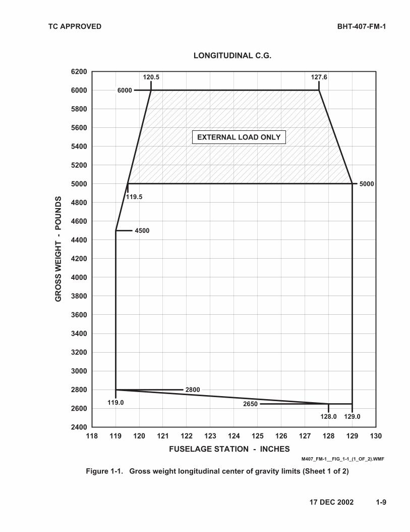
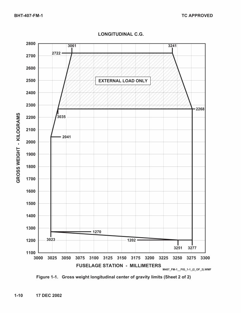
Maximum approved internal GW for takeoff
and landing is 5000 pounds (2268 kg).
Minimum GW for f l ight is 2650 pounds
(1202 kg).
Minimum weight at fuselage station 65.0 is
170 pounds (77.1 kg).
CAUTION
LOADS THAT RESULT IN GW
ABOVE 5000 POUNDS (2268 KG)
SHALL BE CARRIED ON THE
CARGO HOOK AND MUST BE
JETTISONABLE.
Maximum approved GW for f l ight wi th
jettisonable external load is 6000 pounds
(2722 kg).
1-6-B. CENTER OF GRAVITY
The pilot is responsible for determining
weight and balance to ensure gross weight
and center of gravity will remain within limits
throughout each flight. Refer to Section 5 for
loading tables and instructions.
NOTE
Ballast as required to maintain most
forward or most aft CG within GW
flight limits (Figure 1-1). For standard
passenger and fue l load ings ,
applicable Weight Empty Center of
Gravity Chart in BHT-407-MM-1 may
be used to determine required
ballast.
For longitudinal CG limits, refer to Gross
Weight Longitudinal Center of Gravity Limits
chart (Figure 1-1).
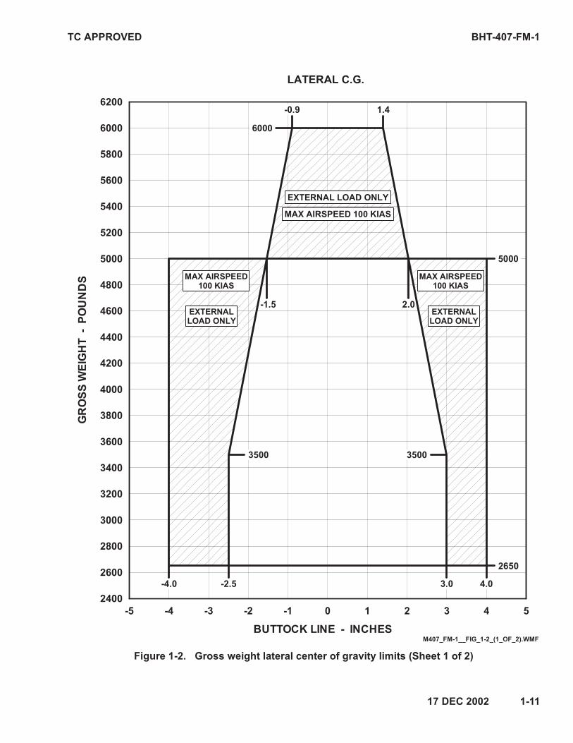
For lateral CG limits, refer to Gross Weight
Lateral Center of Gravity Limits (Figure 1-2).
1-7. AIRSPEED
Basic VNE is 140 KIAS, sea level to 3000 feet
HD. Decrease VNE for ambient conditions in
accordance with AIRSPEED LIMITATIONS
Placards and Decals (Figure 1-3).
VNE at 93.5 to 100% TORQUE (takeoff power)
is 100 KIAS, not to exceed placarded VNE.
TC APPROVED BHT-407-FM-1
30 JUL 2008—Rev. 7———1-5
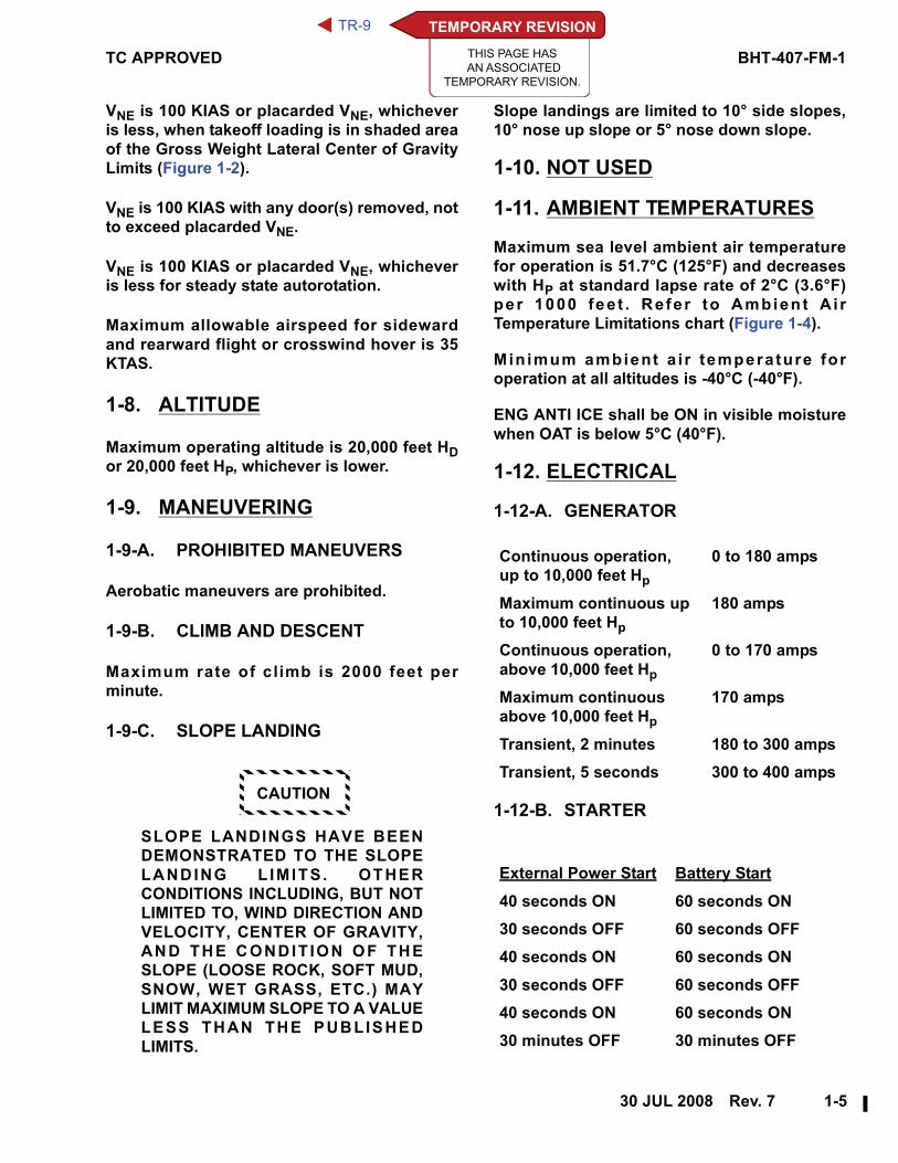
VNE is 100 KIAS or placarded VNE, whichever
is less, when takeoff loading is in shaded area
of the Gross Weight Lateral Center of Gravity
Limits (Figure 1-2).
VNE is 100 KIAS with any door(s) removed, not
to exceed placarded VNE.
VNE is 100 KIAS or placarded VNE, whichever
is less for steady state autorotation.
Maximum allowable airspeed for sideward
and rearward flight or crosswind hover is 35
KTAS.
1-8. ALTITUDE
Maximum operating altitude is 20,000 feet HDor 20,000 feet HP, whichever is lower.
1-9. MANEUVERING
1-9-A. PROHIBITED MANEUVERS
Aerobatic maneuvers are prohibited.
1-9-B. CLIMB AND DESCENT
Maximum rate of climb is 2000 feet per
minute.
1-9-C. SLOPE LANDING
CAUTION
SLOPE LANDINGS HAVE BEEN
DEMONSTRATED TO THE SLOPE
LANDING L IMITS. OTHER
CONDITIONS INCLUDING, BUT NOT
LIMITED TO, WIND DIRECTION AND
VELOCITY, CENTER OF GRAVITY,
AND THE CONDIT ION OF THE
SLOPE (LOOSE ROCK, SOFT MUD,
SNOW, WET GRASS, ETC.) MAY
LIMIT MAXIMUM SLOPE TO A VALUE
LESS THAN THE PUBLISHED
LIMITS.
Slope landings are limited to 10° side slopes,
10° nose up slope or 5° nose down slope.
1-10. NOT USED
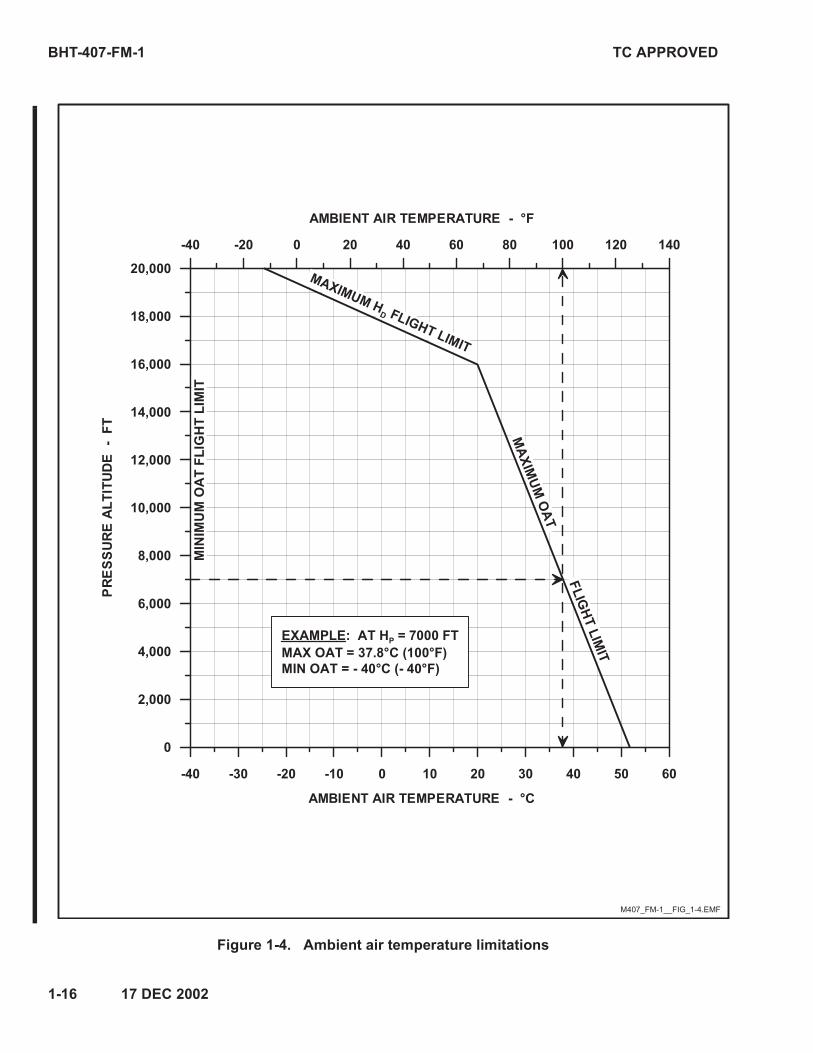
1-11. AMBIENT TEMPERATURES
Maximum sea level ambient air temperature
for operation is 51.7°C (125°F) and decreases
with HP at standard lapse rate of 2°C (3.6°F)
per 1000 fee t . Refer to Ambien t A i r
Temperature Limitations chart (Figure 1-4).
Min imum ambient a i r temperature for
operation at all altitudes is -40°C (-40°F).
ENG ANTI ICE shall be ON in visible moisture
when OAT is below 5°C (40°F).
1-12. ELECTRICAL
1-12-A. GENERATOR
1-12-B. STARTER
Continuous operation,
up to 10,000 feet Hp
0 to 180 amps
Maximum continuous up
to 10,000 feet Hp
180 amps
Continuous operation,
above 10,000 feet Hp
0 to 170 amps
Maximum continuous
above 10,000 feet Hp
170 amps
Transient, 2 minutes 180 to 300 amps
Transient, 5 seconds 300 to 400 amps
External Power Start Battery Start
40 seconds ON 60 seconds ON
30 seconds OFF 60 seconds OFF
40 seconds ON 60 seconds ON
30 seconds OFF 60 seconds OFF
40 seconds ON 60 seconds ON
30 minutes OFF 30 minutes OFF
TEMPORARY REVISION
THIS PAGE HAS
AN ASSOCIATED
TEMPORARY REVISION.
TR-9
BHT-407-FM-1 TC APPROVED
1-6———Rev. 7—30 JUL 2008
NOTE
28 VDC GPU for starting shall be
limited to 500 amps.
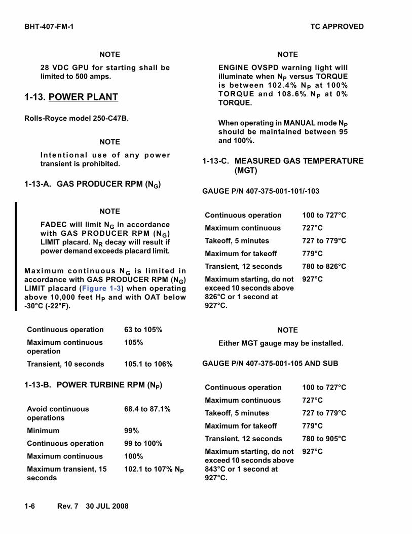
1-13. POWER PLANT
Rolls-Royce model 250-C47B.
NOTE
Inten t iona l use o f any power
transient is prohibited.
1-13-A. GAS PRODUCER RPM (NG)
NOTE
FADEC will limit NG in accordance
with GAS PRODUCER RPM (NG)
LIMIT placard. NR decay will result if
power demand exceeds placard limit.
Maximum cont inuous NG is l im i ted in
accordance with GAS PRODUCER RPM (NG)
LIMIT placard (Figure 1-3) when operating
above 10,000 feet HP and with OAT below
-30°C (-22°F).
1-13-B. POWER TURBINE RPM (NP)
NOTE
ENGINE OVSPD warning light will
illuminate when NP versus TORQUE
is between 102.4% NP a t 100%
TORQUE and 108.6% NP a t 0%
TORQUE.
When operating in MANUAL mode NPshould be maintained between 95
and 100%.
1-13-C. MEASURED GAS TEMPERATURE(MGT)
GAUGE P/N 407-375-001-101/-103
NOTE
Either MGT gauge may be installed.
GAUGE P/N 407-375-001-105 AND SUB
Continuous operation 63 to 105%
Maximum continuous
operation
105%
Transient, 10 seconds 105.1 to 106%
Avoid continuous
operations
68.4 to 87.1%
Minimum 99%
Continuous operation 99 to 100%
Maximum continuous 100%
Maximum transient, 15
seconds
102.1 to 107% NP
Continuous operation 100 to 727°C
Maximum continuous 727°C
Takeoff, 5 minutes 727 to 779°C
Maximum for takeoff 779°C
Transient, 12 seconds 780 to 826°C
Maximum starting, do not
exceed 10 seconds above
826°C or 1 second at
927°C.
927°C
Continuous operation 100 to 727°C
Maximum continuous 727°C
Takeoff, 5 minutes 727 to 779°C
Maximum for takeoff 779°C
Transient, 12 seconds 780 to 905°C
Maximum starting, do not
exceed 10 seconds above
843°C or 1 second at
927°C.
927°C
TC APPROVED BHT-407-FM-1
30 JUL 2008—Rev. 7———1-7
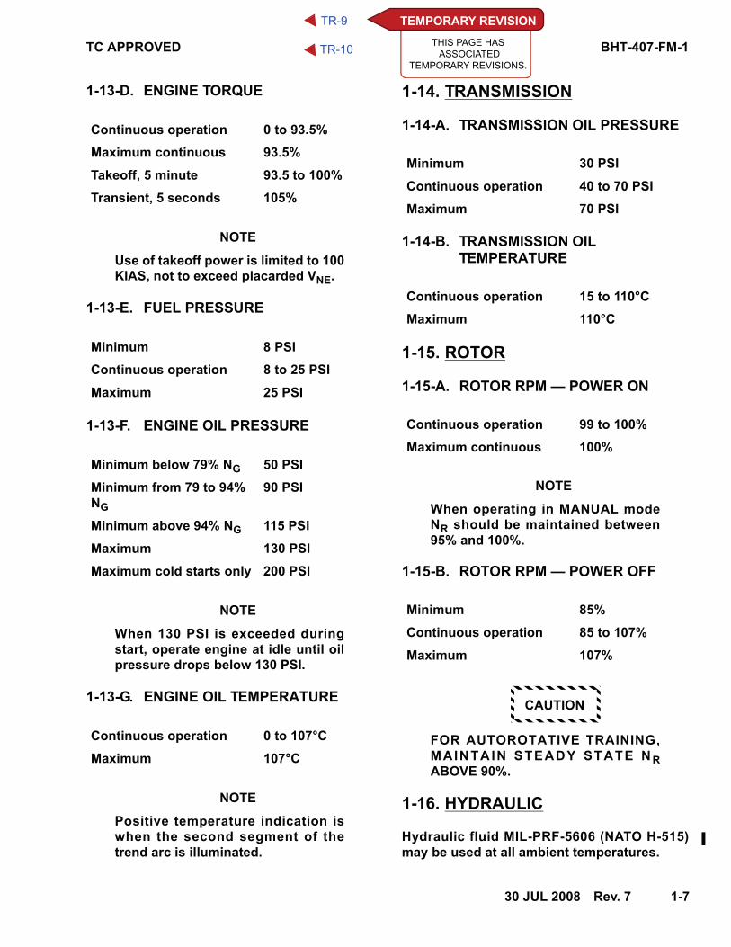
1-13-D. ENGINE TORQUE
NOTE
Use of takeoff power is limited to 100
KIAS, not to exceed placarded VNE.
1-13-E. FUEL PRESSURE
1-13-F. ENGINE OIL PRESSURE
NOTE
When 130 PSI is exceeded during
start, operate engine at idle until oil
pressure drops below 130 PSI.
1-13-G. ENGINE OIL TEMPERATURE
NOTE
Positive temperature indication is
when the second segment of the
trend arc is illuminated.
1-14. TRANSMISSION
1-14-A. TRANSMISSION OIL PRESSURE
1-14-B. TRANSMISSION OILTEMPERATURE
1-15. ROTOR
1-15-A. ROTOR RPM — POWER ON
NOTE
When operating in MANUAL mode
NR should be maintained between
95% and 100%.
1-15-B. ROTOR RPM — POWER OFF
CAUTION
FOR AUTOROTATIVE TRAINING,
MAINTAIN STEADY STATE N RABOVE 90%.
1-16. HYDRAULIC
Hydraulic fluid MIL-PRF-5606 (NATO H-515)
may be used at all ambient temperatures.
Continuous operation 0 to 93.5%
Maximum continuous 93.5%
Takeoff, 5 minute 93.5 to 100%
Transient, 5 seconds 105%
Minimum 8 PSI
Continuous operation 8 to 25 PSI
Maximum 25 PSI
Minimum below 79% NG 50 PSI
Minimum from 79 to 94%
NG
90 PSI
Minimum above 94% NG 115 PSI
Maximum 130 PSI
Maximum cold starts only 200 PSI
Continuous operation 0 to 107°C
Maximum 107°C
Minimum 30 PSI
Continuous operation 40 to 70 PSI
Maximum 70 PSI
Continuous operation 15 to 110°C
Maximum 110°C
Continuous operation 99 to 100%
Maximum continuous 100%
Minimum 85%
Continuous operation 85 to 107%
Maximum 107%
TEMPORARY REVISION
THIS PAGE HAS
ASSOCIATED
TEMPORARY REVISIONS.
TR-9
TR-10
BHT-407-FM-1 TC APPROVED
1-8———Rev. 7—30 JUL 2008
1-17. FUEL AND OIL
1-17-A. FUEL
Fuel conforming to following specifications
may be used at all ambient temperatures:
ASTM-D-6615, Jet B
MIL-DTL-5624, Grade JP-4 (NATO F-40)
Fuels conforming to following specifications
are limited to ambient temperatures of -32°C
(-25°F) and above:
ASTM-D-1655, Jet A or A-1
MIL-DTL-5624, Grade JP-5 (NATO F-44)
MIL-DTL-83133, Grade JP-8 (NATO F-34).
For operations below -32°C (-25°F), refer to
Rolls-Royce Operation and Maintenance
Manual for cold weather fuel and blending
instructions.
1-17-B. OIL
1-17-B-1. OIL — ENGINE
Oil conforming to MIL-PRF-7808 (NATO
O-148), DOD-PRF-85734 or MIL-PRF-23699
(NATO O-156) is l im i ted to ambient
temperatures above -40°C (-40°F).
NOTE
Refer to Rolls-Royce Operation and
Maintenance Manual and
BHT-407-MD-1 manual for approved
oils and mixing of oils of different
brands, types, and manufacturers.
1-17-B-2. OIL — TRANSMISSION AND TAIL
ROTOR GEARBOX
NOTE
It is recommended DOD-PRF-85734
oil be used in transmission and tail
rotor gearbox to maximum extent
allowed by temperature limitations.
Oil conforming to DOD-PRF-85734 is limited
to ambient temperatures above -40°C (-40°F).
Oil conforming to MIL-PRF-7808 (NATO O-148)
is limited to ambient temperatures below
-18°C (0°F).
1-18. ROTOR BRAKE
Rotor brake (if installed) application is limited
to ground operation after engine has been
shut down and NR has decreased to 40% or
lower.
For emergency stops, apply rotor brake any
time after engine is shut down.
Engine starts with rotor brake engaged are
prohibited.
1-19. NOT USED
1-20. INSTRUMENT MARKINGSAND PLACARDS
Refer to Figure 1-3 for Placards and Decals.
Refer to Figure 1-5 for Instrument Markings.
Illustrations shown in Figure 1-5 are artist
representations and may or may not depict
actual approved instruments due to printing
limitations. Instrument operating ranges and
limits shall agree with those presented in this
section.
TC APPROVED BHT-407-FM-1
17 DEC 2002 1-9
Figure 1-1. Gross weight longitudinal center of gravity limits (Sheet 1 of 2)
118 119 120 121 122 123 124 125 126 127 128 129 130
FUSELAGE STATION - INCHES
2400
2600
2800
3000
3200
3400
3600
3800
4000
4200
4400
4600
4800
5000
5200
5400
5600
5800
6000
6200
GR
OS
S W
EIG
HT
-
PO
UN
DS
6000
5000
4500
2800
2650
120.5 127.6
119.5
119.0
128.0 129.0
EXTERNAL LOAD ONLY
LONGITUDINAL C.G.
M407_FM-1__FIG_1-1_(1_OF_2).WMF
BHT-407-FM-1 TC APPROVED
1-10 17 DEC 2002
Figure 1-1. Gross weight longitudinal center of gravity limits (Sheet 2 of 2)
3000 3025 3050 3075 3100 3125 3150 3175 3200 3225 3250 3275 3300
FUSELAGE STATION - MILLIMETERS
1100
1200
1300
1400
1500
1600
1700
1800
1900
2000
2100
2200
2300
2400
2500
2600
2700
2800
GR
OS
S W
EIG
HT
-
KIL
OG
RA
MS
LONGITUDINAL C.G.
2268
EXTERNAL LOAD ONLY
3241 3061
2722
3035
2041
1270
1202 3023
3251 3277
M407_FM-1__FIG_1-1_(2_OF_2).WMF
TC APPROVED BHT-407-FM-1
17 DEC 2002 1-11
Figure 1-2. Gross weight lateral center of gravity limits (Sheet 1 of 2)
-5 -4 -3 -2 -1 0 1 2 3 4 5
BUTTOCK LINE - INCHES
2400
2600
2800
3000
3200
3400
3600
3800
4000
4200
4400
4600
4800
5000
5200
5400
5600
5800
6000
6200
GR
OS
S W
EIG
HT
-
PO
UN
DS
5000
-1.5
LATERAL C.G.
EXTERNAL LOAD ONLY
MAX AIRSPEED 100 KIAS
-0.9 1.4
2.0
-4.0 -2.5 3.0 4.0
3500
2650
3500
6000
EXTERNALLOAD ONLY
MAX AIRSPEED100 KIAS
EXTERNALLOAD ONLY
MAX AIRSPEED100 KIAS
M407_FM-1__FIG_1-2_(1_OF_2).WMF

BHT-407-FM-1 TC APPROVED
1-12 17 DEC 2002
Figure 1-2. Gross weight lateral center of gravity limits (Sheet 2 of 2)
-125 -100 -75 -50 -25 0 25 50 75 100 125
BUTTOCK LINE - MILLIMETERS
1100
1200
1300
1400
1500
1600
1700
1800
1900
2000
2100
2200
2300
2400
2500
2600
2700
2800
GR
OS
S W
EIG
HT
-
KIL
OG
RA
MS
LATERAL C.G.
EXTERNAL LOAD ONLY
MAX AIRSPEED 100 KIAS
EXTERNALLOAD ONLY
MAX AIRSPEED100 KIAS
EXTERNALLOAD ONLY
MAX AIRSPEED100 KIAS
-102 -64 76 102
1588 1588
1202
-39 52
2268
-23 36
2722
M407_FM-1__FIG_1-2_(2_OF_2).WMF

TC APPROVED BHT-407-FM-1
17 DEC 2002 1-13
Figure 1-3. Placards and decals (Sheet 1 of 3)
Airspeed limits shown are valid only for corresponding altitudes and temperatures.
Hatched areas indicate conditions which exceed approved temperature or density altitude
limitations.
Location: Between Pilot and Copilot seats
0 2 4 6 8 10 12 14 16 18 20
52 137
45 139 132 125
40 140 133 126 119
35 140 135 128 120 113
30 140 137 129 122 115 108
25 140 138 131 124 116 109 102 95
20 140 140 133 125 118 111 103 96 89
0 140 140 140 132 125 117 110 103 95 88
-25 140 140 140 135 130 125 119 111 104 97 89
-40 137 133 128 123 118 114 110 105 101 97 93
PRESSURE ALTITUDE FT x 1000
407 AIRSPEED LIMITATIONS - KIAS
OAT
°C
MAXIMUM AUTOROTATION VNE 100 KIAS
EMERGENCY PEDAL
STOP RELEASE
PULL ONLY
MAINT. RESET
REQUIRED
Location: Forward of Overhead Console
M407_FM-1__FIG_1-3_(VNE).WMF
BHT-407-FM-1 TC APPROVED
1-14 Rev. 5 19 FEB 2007
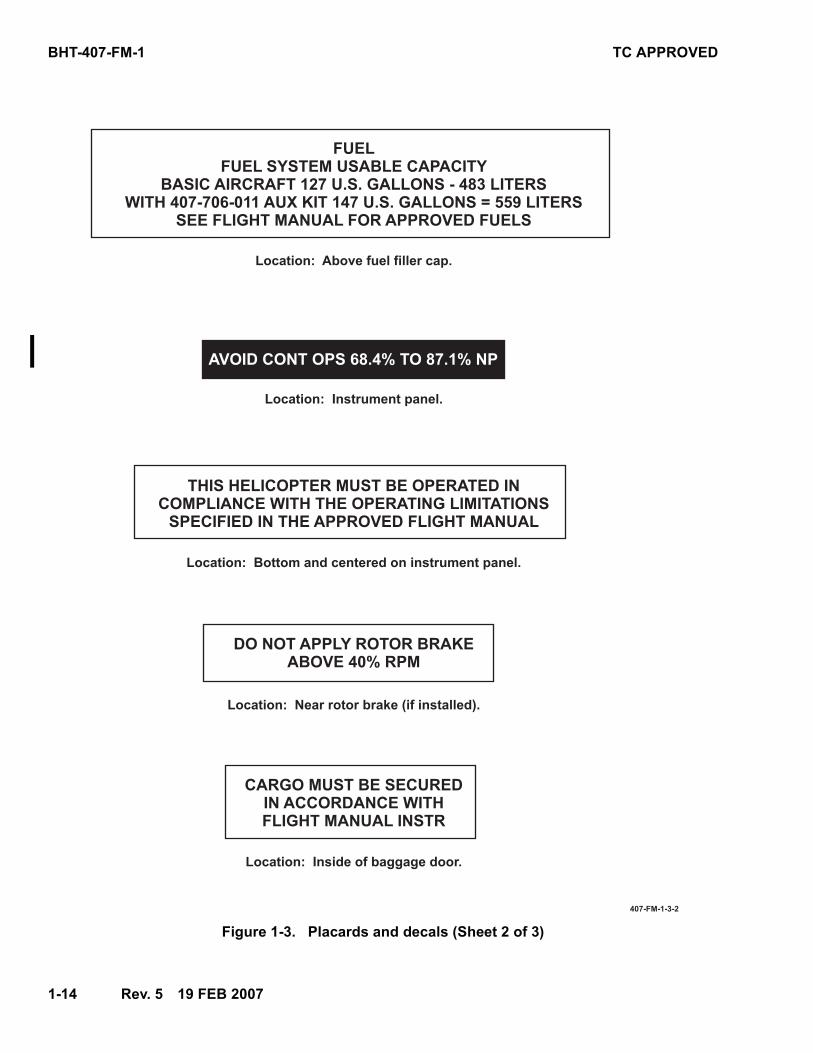
Figure 1-3. Placards and decals (Sheet 2 of 3)
FUELFUEL SYSTEM USABLE CAPACITY
BASIC AIRCRAFT 127 U.S. GALLONS 483 LITERSWITH 407706011 AUX KIT 147 U.S. GALLONS = 559 LITERS
SEE FLIGHT MANUAL FOR APPROVED FUELS
Location: Above fuel filler cap.
THIS HELICOPTER MUST BE OPERATED INCOMPLIANCE WITH THE OPERATING LIMITATIONSSPECIFIED IN THE APPROVED FLIGHT MANUAL
Location: Bottom and centered on instrument panel.
CARGO MUST BE SECUREDIN ACCORDANCE WITHFLIGHT MANUAL INSTR
Location: Inside of baggage door.
407FM132
DO NOT APPLY ROTOR BRAKEABOVE 40% RPM
Location: Near rotor brake (if installed).
Location: Instrument panel.
AVOID CONT OPS 68.4% TO 87.1% NP

TC APPROVED BHT-407-FM-1
30 JUL 2008 Rev. 7 1-15
Figure 1-3. Placards and Decals (Sheet 3 of 3)
FADEC SOFTWARE VERSION 5.202
WITH DIRECT REVERSION TO
MANUAL INSTALLED. REFER TO
FLIGHT MANUAL FOR OPERATION
Location: Instrument panel
MAX ALLOWABLE WEIGHT 250 LBS.
MAX ALLOWABLE WEIGHT PER SQ. FT. 86 LBS.
Location: Inside of baggage door
FUEL CAPACITY
BASIC 869 LBS
WITH AUX 1005 LBS
(JET A AT 15ºC)
Location: Instrument panel
GAS PRODUCER RPM (NG) LIMIT
WHEN ABOVE 10,000 FT HP
MAXIMUM Ng % RPM WITH OAT IS AS FOLLOWS
Location: Above pilot windshield
OAT
ºC
MAX
Ng %99.0
40
99.2
39
99.4
38
99.6
37
99.8
36
100.0
35
100.2
34
100.4
33
100.6
32
100.8
31
101.1
30
Location: Instrument panel and passenger compartment
407_FM_1_0002
TEMPORARY REVISION
THIS PAGE HAS
AN ASSOCIATED
TEMPORARY REVISION.
TR-11
BHT-407-FM-1 TC APPROVED
1-16 17 DEC 2002
Figure 1-4. Ambient air temperature limitations
-40 -30 -20 -10 0 10 20 30 40 50 60
AMBIENT AIR TEMPERATURE - °C
0
2,000
4,000
6,000
8,000
10,000
12,000
14,000
16,000
18,000
20,000
PR
ES
SU
RE
AL
TIT
UD
E
- F
T
-40 -20 0 20 40 60 80 100 120 140
AMBIENT AIR TEMPERATURE - °F
MIN
IMU
M O
AT
FL
IGH
T L
IMIT
MA
XIM
UM
OA
T
EXAMPLE: AT HP = 7000 FT
MAX OAT = 37.8°C (100°F)
MIN OAT = - 40°C (- 40°F)
FL
IGH
TLIM
IT
MAXIMUM HD FLIGHT LIMIT
M407_FM-1__FIG_1-4.EMF

TC APPROVED BHT-407-FM-1
17 DEC 2002 1-17
Figure 1-5. Instrument markings (Sheet 1 of 4)
ENGINE OIL PRESSURE
50 PSI
50 to 90 PSI
90 to 115 PSI
115 to 130 PSI
130 PSI
200 PSI
ENGINE OIL TEMPERATURE
0 to 107°C
107°C
Minimum
Operation below 79% NG RPM
Continuous operation below 94% NG RPM
Maximum for continuous operation
Maximum for cold start
Continuous operation
Maximum
Continuous operation
TRANSMISSION OIL PRESSURE
30 PSI
40 to 70 PSI
70 PSI
TRANSMISSION OIL TEMPERATURE
15 to 110°C
110°C
Minimum
Continuous operation
Maximum
Continuous operation
Maximum
NG (GAS PRODUCER RPM)
63 to 105%
105%
106%
Continuous operation
Maximum continuous operation
Maximum transient, 10 seconds
M407_FM-1__FIG_1-5_(1_OF_4).EPS
BHT-407-FM-1 TC APPROVED
1-18 Rev. 7 30 JUL 2008
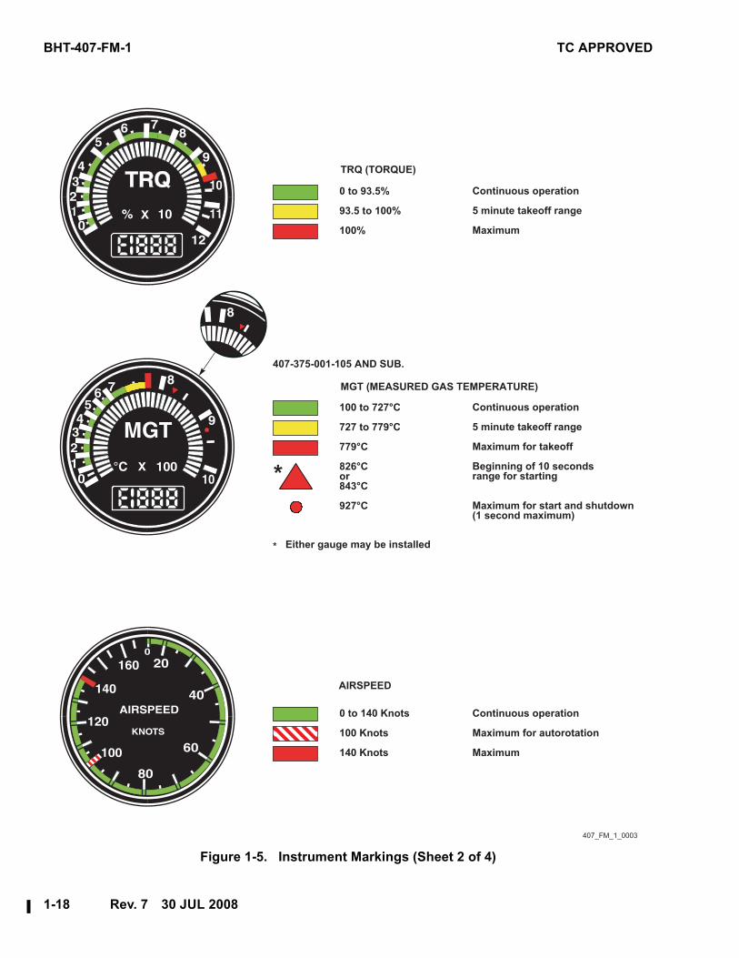
Figure 1-5. Instrument Markings (Sheet 2 of 4)
TRQ (TORQUE)
MGT (MEASURED GAS TEMPERATURE)
Continuous operation
5 minute takeoff range
Maximum for takeoff
Beginning of 10 secondsrange for starting
Maximum for start and shutdown(1 second maximum)
407_FM_1_0003
Continuous operation
Maximum for autorotation
Maximum
407-375-001-105 AND SUB.
Either gauge may be installed*
*
AIRSPEED
0 to 93.5%
93.5 to 100%
100%
0 to 140 Knots
100 Knots
140 Knots
100 to 727°C
727 to 779°C
779°C
826°Cor843°C
927°C
Continuous operation
5 minute takeoff range
Maximum

TC APPROVED BHT-407-FM-1
30 JUL 2008 Rev. 7 1-19
Figure 1-5. Instrument Markings (Sheet 3 of 4)
99%
99 to 100%
100%
Minimum
Continuous operation
Maximum continuous
NP (POWER TURBINE RPM)
407_FM_1_0004
FUEL QUANTITY
0 LBS
195 LBS
869 LBS
1005 LBS
(Jet A 6.8 lbs/gal)
All tanks empty (zero useable)
Forward tank empty
Forward and aft tanks full
Forward, aft and auxiliarytanks full
85%
85 to 107%
107%
Minimum (power off)
Continuous operation (power off)
Maximum (power off)
NR (ROTOR RPM)
407-375-008-101/-103
BHT-407-FM-1 TC APPROVED
1-20 Rev. 3 26 APR 2005
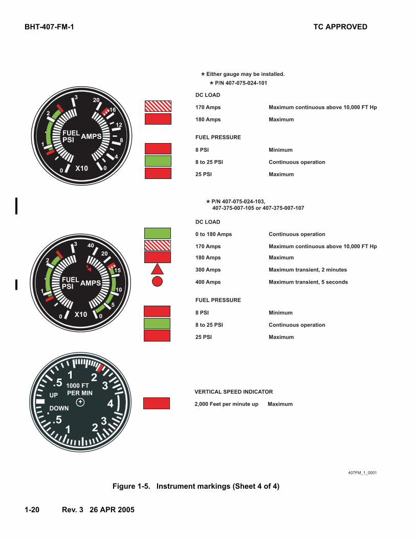
Figure 1-5. Instrument markings (Sheet 4 of 4)
407FM_1_0001
DC LOAD
DC LOAD
FUEL PRESSURE
FUEL PRESSURE
* Either gauge may be installed.
* P/N 407-075-024-101
* P/N 407-075-024-103,
407-375-007-105 or 407-375-007-107
170 Amps
0 to 180 Amps
180 Amps
180 Amps
170 Amps
300 Amps
400 Amps
8 PSI
8 PSI
8 to 25 PSI
8 to 25 PSI
25 PSI
25 PSI
Maximum continuous above 10,000 FT Hp
Continuous operation
Maximum
Maximum
Maximum continuous above 10,000 FT Hp
Maximum transient, 2 minutes
Maximum transient, 5 seconds
Continuous operation
Continuous operation
Maximum
Maximum
Minimum
Minimum
VERTICAL SPEED INDICATOR
2,000 Feet per minute up Maximum
TC APPROVED BHT-407-FM-1
30 JUL 2008 Rev. 7 3-1/3-2
Section 3EMERGENCY/MALFUNCTION PROCEDURES
3
TABLE OF CONTENTS
Paragraph Page
Subject Number Number
Introduction ............................................................................................ 3-1 ........... 3-3
Definitions .............................................................................................. 3-2 ........... 3-3
Engine ..................................................................................................... 3-3 ........... 3-3
Engine Failure .................................................................................... 3-3-A ....... 3-3
Engine Restart in Flight..................................................................... 3-3-B ....... 3-4
Engine Underspeed ........................................................................... 3-3-C ....... 3-6
Engine Overspeed ............................................................................. 3-3-D ....... 3-6
Engine Compressor Stall .................................................................. 3-3-E ....... 3-6
Engine Hot Start/Shutdown .............................................................. 3-3-F........ 3-7
Engine Oil Pressure Low or Fluctuating.......................................... 3-3-G....... 3-7
Engine Oil Temperature High ........................................................... 3-3-H ....... 3-7
Driveshaft Failure............................................................................... 3-3-J........ 3-8
FADEC Failure.................................................................................... 3-3-K ....... 3-8
Fire .......................................................................................................... 3-4 ........... 3-9
Engine Fire on Ground ...................................................................... 3-4-A ....... 3-9
Engine Fire During Flight .................................................................. 3-4-B ....... 3-9
Cabin Smoke or Fumes ..................................................................... 3-4-C ....... 3-9
Tail Rotor ................................................................................................ 3-5 ........... 3-10
Complete Loss of Tail Rotor Thrust................................................. 3-5-A ....... 3-10
Fixed Pitch Failures ........................................................................... 3-5-B ....... 3-10
Hydraulic System................................................................................... 3-6 ........... 3-11
Loss of Hydraulic Pressure .............................................................. 3-6-A ....... 3-11
Flight Control Actuator Malfunction ................................................ 3-6-B ....... 3-12
Electrical System ................................................................................... 3-7 ........... 3-12
Generator Failure ............................................................................... 3-7-A ....... 3-12
Excessive Electrical Load ................................................................. 3-7-B ....... 3-12
Fuel System............................................................................................ 3-8 ........... 3-13
Cyclic Jam .............................................................................................. 3-9 ........... 3-13
Warning, Caution, and Advisory Lights/Messages ............................ 3-10 ......... 3-14
LIST OF TABLES
Table Page
Subject Number Number
Warning (Red) Lights............................................................................. 3-1 ........... 3-15
Caution (Amber) and Advisory (White/Green) Lights......................... 3-2 ........... 3-16

TC APPROVED BHT-407-FM-1
30 JUL 2008 Rev. 7 3-3
Section 3EMERGENCY/MALFUNCTION PROCEDURES
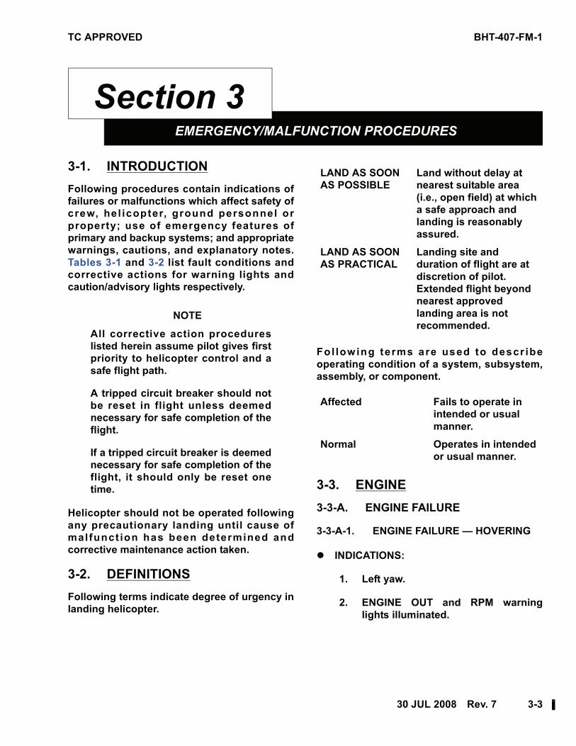
33-1. INTRODUCTION
Following procedures contain indications of
failures or malfunctions which affect safety of
crew, hel icopter, ground personnel or
property; use of emergency features of
primary and backup systems; and appropriate
warnings, cautions, and explanatory notes.
Tables 3-1 and 3-2 list fault conditions and
corrective actions for warning lights and
caution/advisory lights respectively.
NOTE
All corrective action procedures
listed herein assume pilot gives first
priority to helicopter control and a
safe flight path.
A tripped circuit breaker should not
be reset in flight unless deemed
necessary for safe completion of the
flight.
If a tripped circuit breaker is deemed
necessary for safe completion of the
flight, it should only be reset one
time.
Helicopter should not be operated following
any precautionary landing until cause of
malfunct ion has been determined and
corrective maintenance action taken.
3-2. DEFINITIONS
Following terms indicate degree of urgency in
landing helicopter.
Fo l lowing terms are used to descr ibe
operating condition of a system, subsystem,
assembly, or component.
3-3. ENGINE
3-3-A. ENGINE FAILURE
3-3-A-1. ENGINE FAILURE — HOVERING
!"INDICATIONS:
1. Left yaw.
2. ENGINE OUT and RPM warning
lights illuminated.
LAND AS SOON
AS POSSIBLE
Land without delay at
nearest suitable area
(i.e., open field) at which
a safe approach and
landing is reasonably
assured.
LAND AS SOON
AS PRACTICAL
Landing site and
duration of flight are at
discretion of pilot.
Extended flight beyond
nearest approved
landing area is not
recommended.
Affected Fails to operate in
intended or usual
manner.
Normal Operates in intended
or usual manner.
BHT-407-FM-1 TC APPROVED
3-4 17 DEC 2002
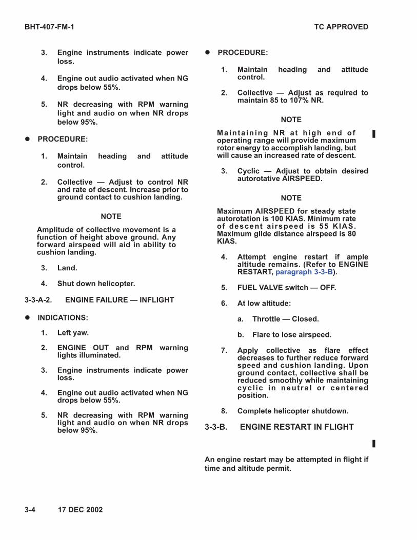
3. Engine instruments indicate power
loss.
4. Engine out audio activated when NG
drops below 55%.
5. NR decreasing with RPM warning
light and audio on when NR drops
below 95%.
!"PROCEDURE:
1. Maintain heading and attitude
control.
2. Collective — Adjust to control NRand rate of descent. Increase prior toground contact to cushion landing.
NOTE
Amplitude of collective movement is afunction of height above ground. Anyforward airspeed will aid in ability tocushion landing.
3. Land.
4. Shut down helicopter.
3-3-A-2. ENGINE FAILURE — INFLIGHT
!"INDICATIONS:
1. Left yaw.
2. ENGINE OUT and RPM warninglights illuminated.
3. Engine instruments indicate powerloss.
4. Engine out audio activated when NGdrops below 55%.
5. NR decreasing with RPM warninglight and audio on when NR dropsbelow 95%.
!"PROCEDURE:
1. Maintain heading and attitudecontrol.
2. Collective — Adjust as required tomaintain 85 to 107% NR.
NOTE
Mainta in ing NR at h igh end ofoperating range will provide maximumrotor energy to accomplish landing, butwill cause an increased rate of descent.
3. Cyclic — Adjust to obtain desiredautorotative AIRSPEED.
NOTE
Maximum AIRSPEED for steady stateautorotation is 100 KIAS. Minimum rateof descent a irspeed is 55 KIAS.Maximum glide distance airspeed is 80KIAS.
4. Attempt engine restart if amplealtitude remains. (Refer to ENGINERESTART, paragraph 3-3-B).
5. FUEL VALVE switch — OFF.
6. At low altitude:
a. Throttle — Closed.
b. Flare to lose airspeed.
7. Apply collective as flare effectdecreases to further reduce forwardspeed and cushion landing. Uponground contact, collective shall bereduced smoothly while maintainingcyc l ic in neut ra l or cente redposition.
8. Complete helicopter shutdown.
3-3-B. ENGINE RESTART IN FLIGHT
An engine restart may be attempted in flight if
time and altitude permit.
TC APPROVED BHT-407-FM-1
17 DEC 2002 3-5
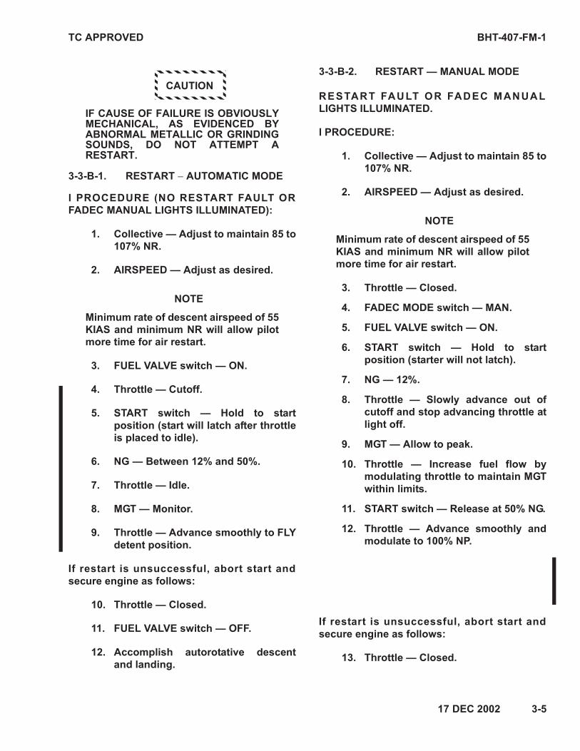
CAUTION
IF CAUSE OF FAILURE IS OBVIOUSLYMECHANICAL, AS EVIDENCED BYABNORMAL METALLIC OR GRINDINGSOUNDS, DO NOT ATTEMPT ARESTART.
3-3-B-1. RESTART − AUTOMATIC MODE
l PROCEDURE (NO RESTART FAULT OR
FADEC MANUAL LIGHTS ILLUMINATED):
1. Collective — Adjust to maintain 85 to
107% NR.
2. AIRSPEED — Adjust as desired.
NOTE
Minimum rate of descent airspeed of 55
KIAS and minimum NR will allow pilot
more time for air restart.
3. FUEL VALVE switch — ON.
4. Throttle — Cutoff.
5. START switch — Hold to start
position (start will latch after throttle
is placed to idle).
6. NG — Between 12% and 50%.
7. Throttle — Idle.
8. MGT — Monitor.
9. Throttle — Advance smoothly to FLY
detent position.
If restart is unsuccessful, abort start and
secure engine as follows:
10. Throttle — Closed.
11. FUEL VALVE switch — OFF.
12. Accomplish autorotative descent
and landing.
3-3-B-2. RESTART — MANUAL MODE
RESTART FAULT OR FADEC MANUAL
LIGHTS ILLUMINATED.
l PROCEDURE:
1. Collective — Adjust to maintain 85 to
107% NR.
2. AIRSPEED — Adjust as desired.
NOTE
Minimum rate of descent airspeed of 55
KIAS and minimum NR will allow pilot
more time for air restart.
3. Throttle — Closed.
4. FADEC MODE switch — MAN.
5. FUEL VALVE switch — ON.
6. START switch — Hold to start
position (starter will not latch).
7. NG — 12%.
8. Throttle — Slowly advance out of
cutoff and stop advancing throttle at
light off.
9. MGT — Allow to peak.
10. Throttle — Increase fuel flow by
modulating throttle to maintain MGT
within limits.
11. START switch — Release at 50% NG.
12. Throttle — Advance smoothly and
modulate to 100% NP.
If restart is unsuccessful, abort start and
secure engine as follows:
13. Throttle — Closed.
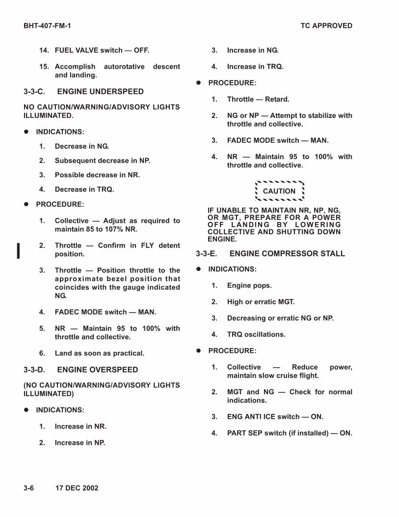
BHT-407-FM-1 TC APPROVED
3-6 17 DEC 2002
14. FUEL VALVE switch — OFF.
15. Accomplish autorotative descent
and landing.
3-3-C. ENGINE UNDERSPEED
NO CAUTION/WARNING/ADVISORY LIGHTS
ILLUMINATED.
!"INDICATIONS:
1. Decrease in NG.
2. Subsequent decrease in NP.
3. Possible decrease in NR.
4. Decrease in TRQ.
!"PROCEDURE:
1. Collective — Adjust as required to
maintain 85 to 107% NR.
2. Throttle — Confirm in FLY detent
position.
3. Throttle — Position throttle to the
approximate bezel position that
coincides with the gauge indicated
NG.
4. FADEC MODE switch — MAN.
5. NR — Maintain 95 to 100% with
throttle and collective.
6. Land as soon as practical.
3-3-D. ENGINE OVERSPEED
(NO CAUTION/WARNING/ADVISORY LIGHTS
ILLUMINATED)
!"INDICATIONS:
1. Increase in NR.
2. Increase in NP.
3. Increase in NG.
4. Increase in TRQ.
!"PROCEDURE:
1. Throttle — Retard.
2. NG or NP — Attempt to stabilize with
throttle and collective.
3. FADEC MODE switch — MAN.
4. NR — Maintain 95 to 100% with
throttle and collective.
CAUTION
IF UNABLE TO MAINTAIN NR, NP, NG,OR MGT, PREPARE FOR A POWEROFF LANDING BY LOWERINGCOLLECTIVE AND SHUTTING DOWNENGINE.
3-3-E. ENGINE COMPRESSOR STALL
!"INDICATIONS:
1. Engine pops.
2. High or erratic MGT.
3. Decreasing or erratic NG or NP.
4. TRQ oscillations.
!"PROCEDURE:
1. Collective — Reduce power,
maintain slow cruise flight.
2. MGT and NG — Check for normal
indications.
3. ENG ANTI ICE switch — ON.
4. PART SEP switch (if installed) — ON.

TC APPROVED BHT-407-FM-1
17 DEC 2002 3-7
5. HEATER switch (if installed) — ON.
NOTE
Severity of compressor stalls will
dictate if engine should be shut down
and treated as an engine failure. Violent
stalls can cause damage to engine and
drive system components, and must be
handled as an emergency condition.
Stalls of a less severe nature (one or
two low intensity pops) may permit
continued operation of engine at a
reduced power leve l , avo id ing
condition that resulted in compressor
stall.
If pilot elects to continue flight:
6. Collective — Increase slowly to
achieve desired power level.
7. MGT and NG — Monitor for normal
response.
8. Land as soon as practical.
If pilot elects to shut down engine:
9. Enter autorotation.
10. Throttle — Closed.
11. FUEL VALVE switch — OFF.
12. Collective — Adjust as required tomaintain 85 to 107% NR.
13. Cyclic — Adjust as required tomaintain desired AIRSPEED.
14. Prepare for power-off landing.
3-3-F. ENGINE HOT START/SHUTDOWN
!"INDICATIONS:
1. Excessive MGT.
2. Visible smoke or fire.
!"PROCEDURE:
1. Throttle — Closed.
2. FUEL VALVE switch — OFF.
NOTE
Starter will remain engaged until MGTdecreases to 150 °C and thenautomatically disengage. Starter maybe manually engaged by holdingSTARTER switch forward.
3. STARTER switch — Ensure starter ismotoring engine until MGT stabilizesat normal temperature.
4. Shut down helicopter.
3-3-G. ENGINE OIL PRESSURE LOW OR FLUCTUATING
!"INDICATIONS:
1. Engine oil pressure below minimum.
2. Engine oil pressure fluctuatingabnormally.
!"PROCEDURE:
1. Engine oil pressure and temperature
— Monitor.
2. Land as soon as practical.
3-3-H. ENGINE OIL TEMPERATURE HIGH
!"INDICATIONS:
1. Engine oil temperature increasingabove normal.
2. Engine oil temperature abovemaximum.
!"PROCEDURE:
Land as soon as practical.
BHT-407-FM-1 TC APPROVED
3-8 17 DEC 2002
3-3-J. DRIVESHAFT FAILURE
WARNING
FAILURE OF MAIN DRIVESHAFT TO
TRANSMISSION WILL RESULT IN
COMPLETE LOSS OF POWER TO MAIN
ROTOR. ALTHOUGH COCKPIT
INDICATIONS FOR A DRIVESHAFT
FAILURE ARE SIMILAR TO AN ENGINE
OVERSPEED, IT IS IMPERATIVE THAT
A U T O R O T A T I V E F L I G H T
PROCEDURES BE ESTABLISHED
IMMEDIATELY. FAILURE TO REACT
IMMEDIATELY TO LOW RPM AUDIO,
RPM LIGHT AND NP/NR TACHOMETER
CAN RESULT IN LOSS OF CONTROL.
!"INDICATIONS:
1. Left yaw
2. Rapid decrease in NR
3. Rapid increase in NP
4. LOW RPM audio horn
5. Illumination of RPM light
6. Possible increase in noise level due
to overspeed ing engine and
driveshaft breakage.
NOTE
Engine overspeed trip system will
activate at 118.5% NP causing fuel flow
to go to minimum. After initial
overspeed, FADEC will adjust fuel flow
to maintain engine at 100% NP.
!"PROCEDURE:
1. Maintain heading and attitude
control.
2. Collective — Adjust as required to
maintain 85 to 107% NR.
NOTE
Minimum rate of descent airspeed is 55
KIAS. Maximum glide distance
airspeed is 80 KIAS.
3. Cyclic — Adjust to obtain desired
autorotative airspeed.
NOTE
To maintain tail rotor effectiveness do
not shutdown engine.
4. Landing — Complete autorotative
landing.
5. Complete helicopter shutdown.
3-3-K. FADEC FAILURE
NOTE
Takeoff power may not be available in
the MAN mode. Maximum continuous
power will be available for all ambient
conditions.
!"INDICATIONS
1. FADEC fail audio activated.
2. FA D E C FA I L w a r n i n g l i g h t
illuminated.
3. FADEC MANUAL caution l ight
illuminated.
4. AUTO RELIGHT advisory l ight
illuminated.
5. FADEC MODE switch MAN light
illuminated.
TC APPROVED BHT-407-FM-1
30 JUL 2008 Rev. 7 3-9
!"PROCEDURE:
WARNING
WITHIN 2 TO 7 SECONDS AFTER
THE FADEC FAIL WARNING NR/NP
MAY INCREASE RAPIDLY,
REQUIRING POSITIVE MOVEMENTS
OF COLLECTIVE AND THROTTLE
TO CONTROL NR.
1. Throttle — If time permits, match
thro t t le beze l pos i t ion to NG
indication.
2. NR/NP — Maintain 95 to 100% with
collective and throttle.
3. FADEC MODE switch — Depress one
time, muting FADEC fail audio.
NOTE
Depressing FADEC MODE switch
one time, will only mute FADEC fail
audio. This step should not be
accomplished until pilot is firmly
established in MAN control.
4. Land as soon as practical.
5. Normal shutdown if possible.
3-4. FIRE
3-4-A. ENGINE FIRE ON GROUND
!"INDICATIONS:
1. Smoke
2. Fumes
3. Fire
!"PROCEDURE:
1. Throttle — Closed.
2. FUEL VALVE switch — OFF.
3. GEN switch — OFF.
4. BATT switch — OFF.
5. Rotor brake (if installed) — Engage.
6. Exit helicopter.
3-4-B. ENGINE FIRE DURING FLIGHT
!"INDICATIONS:
1. Smoke
2. Fumes
3. Fire
!"PROCEDURE:
1. Inflight — Immediately enter
autorotation.
2. Throttle — Closed.
3. FUEL VALVE switch — OFF.
4. If time permits, FUEL BOOST/XFR
circuit breaker switches — OFF.
5. Execute autorotative descent and
landing.
6. BATT switch — OFF.
NOTE
Do not restart engine until corrective
maintenance has been performed.
3-4-C. CABIN SMOKE OR FUMES
!"INDICATIONS:
1. Smoke
2. Fumes
BHT-407-FM-1 TC APPROVED
3-10 17 DEC 2002
!"PROCEDURE:
1. Inflight — Start descent
2. AIR COND BLO switch (if installed)
— OFF
3. HEATER switch (if installed) — OFF
4. All vents — Open
5. Side windows — Open
If time and altitude permits:
6. Source — Attempt to identify and
secure.
7. If source is identified and smoke
and/or fumes still persist — Land as
soon as possible.
8. If source is identified and smoke
and/or fumes are cleared — Land as
soon as practical.
3-5. TAIL ROTOR
There is no single emergency procedure for
all types of antitorque malfunctions. One key
to a pilot successfully handling a tail rotor
emergency lies in the abil ity to quickly
recognize the type of malfunction that has
occurred.
3-5-A. COMPLETE LOSS OF TAIL ROTOR THRUST
This is a situation involving a break in drive
system (e.g., severed driveshaft), wherein tail
rotor stops turning and delivers no thrust.
!"INDICATIONS:
1. Uncontrollable yawing to right (leftside slip).
2. Nose down tucking.
3. Possible roll of fuselage.
NOTE
Severity of initial reaction of helicopterwill be affected by AIRSPEED, CG,power being used, and HD.
!"PROCEDURE:
3-5-A-1. HOVERING
Close thrott le and perform a hovering
autorotation landing. A slight rotation can be
expected on touchdown.
3-5-A-2. IN-FLIGHT
Reduce throttle to idle, immediately enter
autorotat ion, and maintain a minimum
AIRSPEED of 55 KIAS during descent.
NOTE
When a suitable landing site is not
available, vertical f in may permit
controlled flight at low power levels
and sufficient AIRSPEED. During final
stages of approach, a mild flare should
be executed, making sure all power to
rotor is off. Maintain helicopter in a
slight flare and smoothly use collective
to execute a soft, slightly nose-high
landing. Landing on aft portion of skids
will tend to correct side drift. This
technique will, in most cases, result in
a run-on type landing.
CAUTION
IN A RUN-ON TYPE LANDING AFTERTOUCHING DOWN, DO NOT USECYCLIC TO REDUCE FORWARDSPEED.
3-5-B. FIXED PITCH FAILURES
This is a situation involving inability to
change tail rotor thrust (blade angle) with anti-
torque pedals.
TC APPROVED BHT-407-FM-1
17 DEC 2002 3-11
!"INDICATIONS:
1. Lack of directional response.
2. Locked pedals.
NOTE
If pedals cannot be moved with a
moderate amount of force, do not
attempt to apply a maximum effort,
since a more serious malfunction could
result. If helicopter is in a trimmed
condition when malfunction occurs,
TRQ and AIRSPEED should be noted
and helicopter flown to a suitable
landing area. Certain combinations of
TRQ, NR, and AIRSPEED will correct a
yaw attitude, and these combinations
should be used to land helicopter.
!"PROCEDURE:
NOTE
Pull pedal stop emergency release to
ensure pedal stop is retracted.
3-5-B-1. HOVERING
Do not close throttle unless a severe right
yaw occurs. If pedals lock in any position at a
hover, land ing f rom a hover can be
accomplished with greater safety under
power-controlled flight rather than by closing
throttle and entering autorotation.
3-5-B-2. IN-FLIGHT — LEFT PEDAL
APPLIED
In a high power condition, helicopter will yaw
to left when power is reduced. Power and
AIRSPEED should be adjusted to a value
where a comfortable yaw angle can be
maintained. If AIRSPEED is increased, vertical
f in wi l l become more ef fect ive and an
increased left yaw attitude will develop. To
accomplish landing, establish a power-on
approach with sufficiently low AIRSPEED
(zero if necessary) to attain a rate of descent
with a comfortable sideslip angle. (A decrease
in NP decreases ta i l ro tor thrust . ) As
collective is increased just before touchdown,
left yaw will be reduced.
3-5-B-3. IN-FLIGHT — RIGHT PEDAL
APPLIED
In cruise flight or reduced power situation,
helicopter will yaw to right when power is
increased. A low power, run-on type landing
will be necessary by gradually reducing
throttle to maintain heading while adding
collective to cushion landing. If right yaw
becomes excessive, close throttle completely.
3-6. HYDRAULIC SYSTEM
3-6-A. LOSS OF HYDRAULIC PRESSURE
!"INDICATIONS:
1. HYDRAULIC SYSTEM caution light
illuminated.
2. Grinding or howling noise from
pump.
3. Increase in force required to move
flight controls.
4. Feedback forces may be evident
during flight control movement.
!"PROCEDURE:
1. Reduce AIRSPEED to 70 to 100
KIAS.
2. HYD SYSTEM circuit breaker — Out.
If hydraulic power is not restored,
push breaker in.
3. HYD SYS switch — HYD SYS; OFF if
hydraulic power is not restored.
BHT-407-FM-1 TC APPROVED
3-12 17 DEC 2002
4. For extended flight set comfortable
AIRSPEED, up to 120 KIAS, to
minimize control forces.
5. Land as soon as practical.
6. A run-on landing at effective
t rans la t iona l l i ft speed
(approx imate ly 15 knots ) is
recommended.
3-6-B. FLIGHT CONTROL ACTUATOR MALFUNCTION
An actuator hardover can occur in any flight
control axis, but a cyclic cam jam will only
occur in the fore and aft axis. An actuator
hardover is manifested by uncommanded
movements of one or two flight controls. If
two controls move, the pilot will find one of
these controls will require a higher than
norma l contro l fo rce to oppose the
movement. This force cannot be “trimmed” to
zero without turning the HYD SYS switch OFF.
Once the hydraulic boost is OFF, the forces
on the affected flight control will be similar to
the “normal” hydraulic off forces.
!"INDICATIONS:
1. Uncommanded flight control
movements
2. High flight control forces to oppose
movement in one axis
3. Feedback forces only in affected
flight control axis
4. Flight control forces normal in
unaffected axis
!"PROCEDURE:
1. Attitude — Maintain
2. HYD SYS switch — OFF
3. AIRSPEED — Set to 70 to 100 KIAS
4. Land as soon as possible using
procedure from paragraph 3-6-A
3-7. ELECTRICAL SYSTEM
3-7-A. GENERATOR FAILURE
!"INDICATIONS:
1. GEN FAIL caution light illuminated.
2. AMPS indicates 0.
3. Voltmeter — Approximately 24 volts
!"PROCEDURE:
1. GENERATOR FIELD and
GENERATOR RESET c i rcu i t
breakers — Check in.
2. GEN switch — RESET; then GEN.
3. If power is not restored, place GEN
switch to OFF; land as soon as
practical.
NOTE
With generator OFF, a fully charged
battery will provide approximately 21
minutes of power for basic helicopter
and one VHF COMM radio (35 minutes
with optional 28 ampere/hour battery).
3-7-B. EXCESSIVE ELECTRICAL LOAD
!"INDICATIONS:
1. AMPS indicates excessive load.
2. Smoke or fumes.
!"PROCEDURE:
1. GEN switch — OFF.
2. BATT switch — OFF.
TC APPROVED BHT-407-FM-1
19 FEB 2007 Rev. 5 3-13
3. FUEL BOOST/XFR LEFT circuit
breaker switch — LEFT (on).
WARNING
PRIOR TO BATTERY DEPLETION,
ALTITUDE MUST BE REDUCED
BELOW 8000 FEET HP (JET A) OR 4000
FEET HP (JET B). UNUSABLE FUEL
MAY BE AS HIGH AS 150 POUNDS
AFTER THE BATTERY IS DEPLETED
DUE TO INABILITY TO TRANSFER
FUEL FROM FORWARD CELLS.
NOTE
With battery and generator OFF, an
80% charged battery will operate left
fuel boost pump and left fuel transfer
pump for approximately 1.7 hours (2.8
hours with optional 28 ampere/hour
battery).
4. Airspeed — 60 KIAS or less.
NOTE
Pedal stop disengages with loss of
electrical power.
5. Land as soon as practical.
NOTE
When throttle is repositioned to the idle
stop (during engine shutdown) the
PMA will go offline and the engine may
flame out.
3-8. FUEL SYSTEM
DUAL FUEL TRANSFER FAILURE
!"INDICATIONS:
1. L/FUEL XFR and R/FUEL XFR
caution lights illuminate.
2. Last 150 pounds of fuel in forward
cell may not be usable.
3. Fuel will stop transferring from
forward to a ft fue l ce l l a t
approximately 345 pounds total
indicated fuel.
!"PROCEDURE:
1. LEFT and RIGHT FUEL BOOST/XFR
circuit breaker switches — Check
ON.
2. Determine FUEL QTY in forward cell.
3. Subtract quantity of fuel trapped in
forward cell from total to determine
usable fuel remaining.
4. Plan landing accordingly.
3-9. CYCLIC CAM JAM
A cyclic cam jam can only occur in the fore
and aft axis, whereas, an actuator hardover
can occur in any flight control axis. A cyclic
cam jam is manifested when a commanded
control movement requires a higher than
normal fore and aft spring force. The force felt
when moving the cyclic fore and aft with a
cam jam is the result of overriding a spring
capsule.
!"INDICATIONS:
1. High (approximately 15 pounds) fore
and aft cyclic control forces.
2. Normal pedal, collective and lateral
cyclic control forces.
!"PROCEDURE:
1. Helicopter pitch attitude — Maintain
normal pitch attitudes with forward
or aft cyclic force.
BHT-407-FM-1 TC APPROVED
3-14 17 DEC 2002
CAUTION
DO NOT TURN HYDRAULIC BOOSTOFF
2. Land as soon as practical.
3-10. WARNING, CAUTION, AND ADVISORY LIGHTS/MESSAGES
Red warn ing l ights /messages , fau l t
condit ions, and corrective actions are
presented in Table 3-1.
Amber caution and White advisory lights/
messages and correc t ive ac t ions are
presented in Table 3-2.
TC APPROVED BHT-407-FM-1
17 DEC 2002 3-15
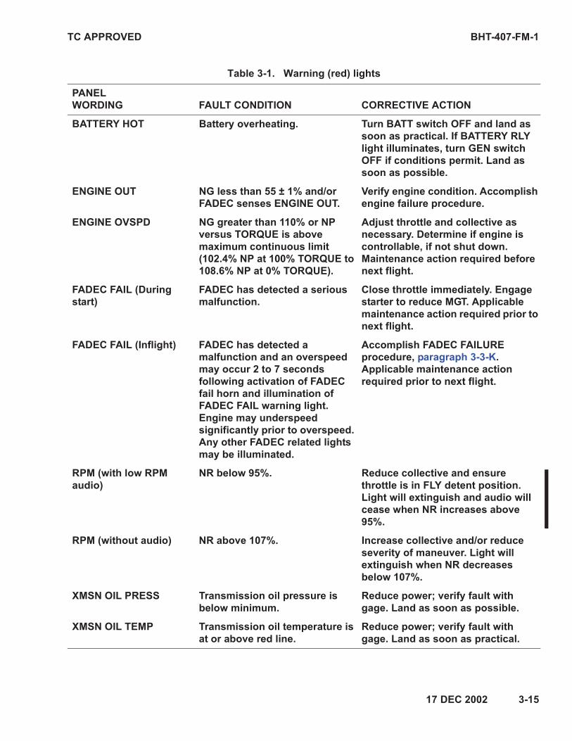
Table 3-1. Warning (red) lights
PANEL
WORDING FAULT CONDITION CORRECTIVE ACTION
BATTERY HOT Battery overheating. Turn BATT switch OFF and land as
soon as practical. If BATTERY RLY
light illuminates, turn GEN switch
OFF if conditions permit. Land as
soon as possible.
ENGINE OUT NG less than 55 ± 1% and/or
FADEC senses ENGINE OUT.
Verify engine condition. Accomplish
engine failure procedure.
ENGINE OVSPD NG greater than 110% or NP
versus TORQUE is above
maximum continuous limit
(102.4% NP at 100% TORQUE to
108.6% NP at 0% TORQUE).
Adjust throttle and collective as
necessary. Determine if engine is
controllable, if not shut down.
Maintenance action required before
next flight.
FADEC FAIL (During
start)
FADEC has detected a serious
malfunction.
Close throttle immediately. Engage
starter to reduce MGT. Applicable
maintenance action required prior to
next flight.
FADEC FAIL (Inflight) FADEC has detected a
malfunction and an overspeed
may occur 2 to 7 seconds
following activation of FADEC
fail horn and illumination of
FADEC FAIL warning light.
Engine may underspeed
significantly prior to overspeed.
Any other FADEC related lights
may be illuminated.
Accomplish FADEC FAILURE
procedure, paragraph 3-3-K.
Applicable maintenance action
required prior to next flight.
RPM (with low RPM
audio)
NR below 95%. Reduce collective and ensure
throttle is in FLY detent position.
Light will extinguish and audio will
cease when NR increases above
95%.
RPM (without audio) NR above 107%. Increase collective and/or reduce
severity of maneuver. Light will
extinguish when NR decreases
below 107%.
XMSN OIL PRESS Transmission oil pressure is
below minimum.
Reduce power; verify fault with
gage. Land as soon as possible.
XMSN OIL TEMP Transmission oil temperature is
at or above red line.
Reduce power; verify fault with
gage. Land as soon as practical.
BHT-407-FM-1 TC APPROVED
3-16 17 DEC 2002
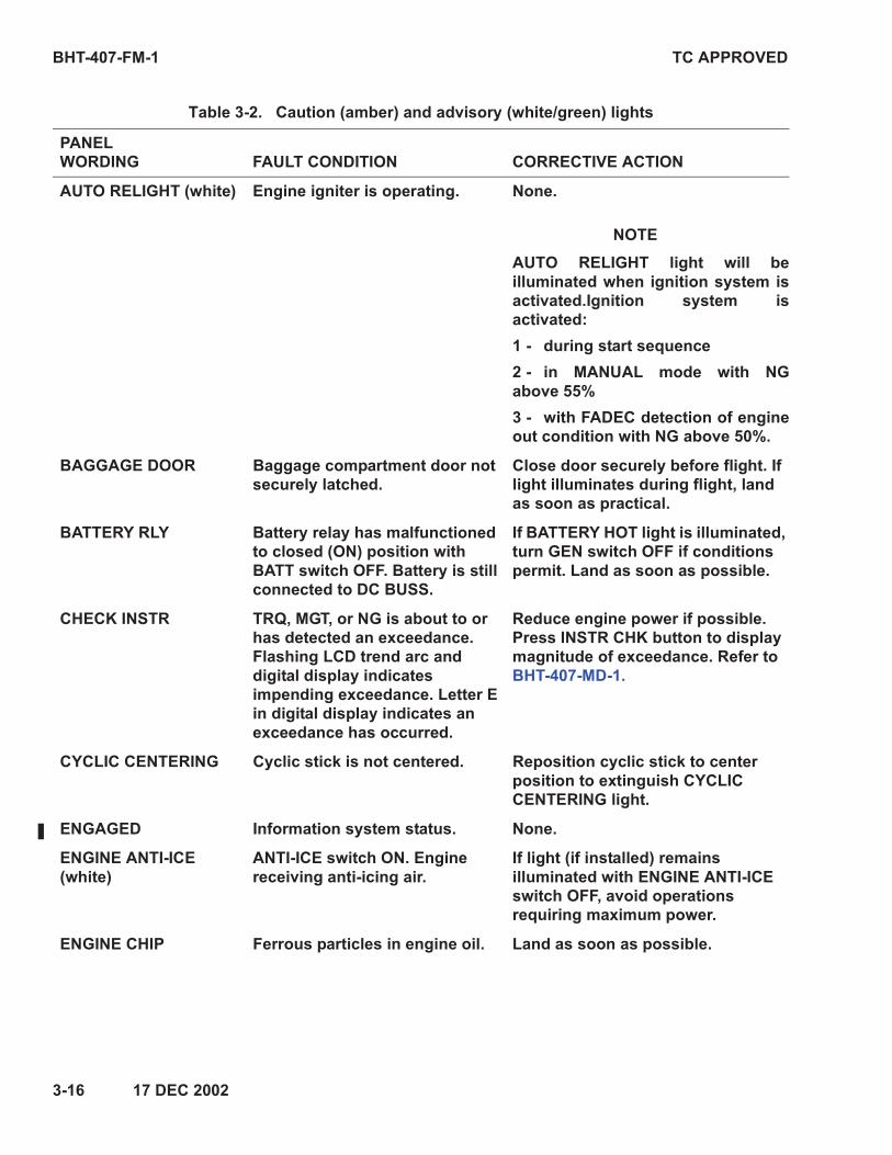
Table 3-2. Caution (amber) and advisory (white/green) lights
PANEL
WORDING FAULT CONDITION CORRECTIVE ACTION
AUTO RELIGHT (white) Engine igniter is operating. None.
NOTE
AUTO RELIGHT light will be
illuminated when ignition system is
activated.Ignition system is
activated:
1 - during start sequence
2 - in MANUAL mode with NG
above 55%
3 - with FADEC detection of engine
out condition with NG above 50%.
BAGGAGE DOOR Baggage compartment door not
securely latched.
Close door securely before flight. If
light illuminates during flight, land
as soon as practical.
BATTERY RLY Battery relay has malfunctioned
to closed (ON) position with
BATT switch OFF. Battery is still
connected to DC BUSS.
If BATTERY HOT light is illuminated,
turn GEN switch OFF if conditions
permit. Land as soon as possible.
CHECK INSTR TRQ, MGT, or NG is about to or
has detected an exceedance.
Flashing LCD trend arc and
digital display indicates
impending exceedance. Letter E
in digital display indicates an
exceedance has occurred.
Reduce engine power if possible.
Press INSTR CHK button to display
magnitude of exceedance. Refer to
BHT-407-MD-1.
CYCLIC CENTERING Cyclic stick is not centered. Reposition cyclic stick to center
position to extinguish CYCLIC
CENTERING light.
ENGAGED Information system status. None.
ENGINE ANTI-ICE
(white)
ANTI-ICE switch ON. Engine
receiving anti-icing air.
If light (if installed) remains
illuminated with ENGINE ANTI-ICE
switch OFF, avoid operations
requiring maximum power.
ENGINE CHIP Ferrous particles in engine oil. Land as soon as possible.

TC APPROVED BHT-407-FM-1
17 DEC 2002 3-17
FADEC DEGRADED
(Inflight)
FADEC ECU operation is
degraded which may result in NR
droop, NR lag, or reduced
maximum power capability.
Remain in AUTO mode. Fly
helicopter smoothly and
nonaggressively. Land as soon as
practical.
NOTE
It may be necessary to use FUEL
VALVE switch to shut down engine
after landing.
Applicable maintenance action
required prior to next flight.
FADEC DEGRADED
(With engine shutdown)
FADEC ECU has recorded a fault
during previous flight or a
current fault has been detected.
Position throttle to idle; if light
extinguishes, fault is from previous
flight. Applicable maintenance
action required prior to next flight.
FADEC FAULT PMA and or MGT, NP or NG
automatic limiting circuit(s) not
functional.
Remain in AUTO mode. Land as
soon as practical. Applicable
maintenance action required prior
to next flight.
FADEC MANUAL FADEC is operating in MANUAL
mode. No automatic governing is
available. AUTO RELIGHT light
will be illuminated.
Fly helicopter smoothly and
nonaggressively. Maintain NR with
coordinated throttle and collective
movements. Land as soon as
practical.
FLOAT ARM FLOAT ARM switch is ON. Float
inflation solenoid is armed.
Normal operation for takeoff and
landing over water. FLOAT ARM
switch — OFF. If light remains
illuminated, FLOATS circuit breaker
— Out. Land as soon as practical.
NOTE
With float inflation solenoid armed,
flight should not exceed 60 KIAS and
500 feet AGL.
FLOAT TEST (green) Float system in test mode. None.
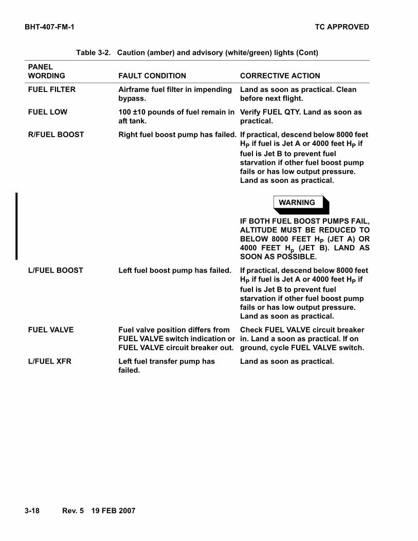
Table 3-2. Caution (amber) and advisory (white/green) lights (Cont)
PANEL
WORDING FAULT CONDITION CORRECTIVE ACTION
BHT-407-FM-1 TC APPROVED
3-18 Rev. 5 19 FEB 2007
FUEL FILTER Airframe fuel filter in impending
bypass.
Land as soon as practical. Clean
before next flight.
FUEL LOW 100 ±10 pounds of fuel remain in
aft tank.
Verify FUEL QTY. Land as soon as
practical.
R/FUEL BOOST Right fuel boost pump has failed. If practical, descend below 8000 feet
HP if fuel is Jet A or 4000 feet HP if
fuel is Jet B to prevent fuel
starvation if other fuel boost pump
fails or has low output pressure.
Land as soon as practical.
WARNING
IF BOTH FUEL BOOST PUMPS FAIL,
ALTITUDE MUST BE REDUCED TO
BELOW 8000 FEET HP (JET A) OR
4000 FEET Hp (JET B). LAND AS
SOON AS POSSIBLE.
L/FUEL BOOST Left fuel boost pump has failed. If practical, descend below 8000 feet
HP if fuel is Jet A or 4000 feet HP if
fuel is Jet B to prevent fuel
starvation if other fuel boost pump
fails or has low output pressure.
Land as soon as practical.
FUEL VALVE Fuel valve position differs from
FUEL VALVE switch indication or
FUEL VALVE circuit breaker out.
Check FUEL VALVE circuit breaker
in. Land a soon as practical. If on
ground, cycle FUEL VALVE switch.
L/FUEL XFR Left fuel transfer pump has
failed.
Land as soon as practical.
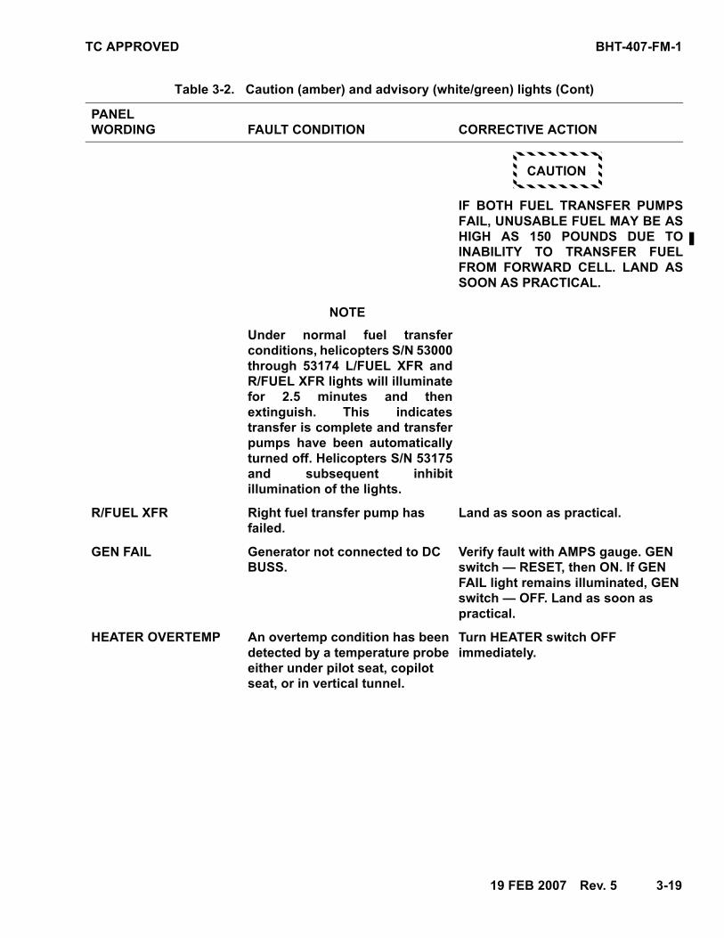
Table 3-2. Caution (amber) and advisory (white/green) lights (Cont)
PANEL
WORDING FAULT CONDITION CORRECTIVE ACTION
TC APPROVED BHT-407-FM-1
19 FEB 2007 Rev. 5 3-19
CAUTION
IF BOTH FUEL TRANSFER PUMPS
FAIL, UNUSABLE FUEL MAY BE AS
HIGH AS 150 POUNDS DUE TO
INABILITY TO TRANSFER FUEL
FROM FORWARD CELL. LAND AS
SOON AS PRACTICAL.
NOTE
Under normal fuel transfer
conditions, helicopters S/N 53000
through 53174 L/FUEL XFR and
R/FUEL XFR lights will illuminate
for 2.5 minutes and then
extinguish. This indicates
transfer is complete and transfer
pumps have been automatically
turned off. Helicopters S/N 53175
and subsequent inhibit
illumination of the lights.
R/FUEL XFR Right fuel transfer pump has
failed.
Land as soon as practical.
GEN FAIL Generator not connected to DC
BUSS.
Verify fault with AMPS gauge. GEN
switch — RESET, then ON. If GEN
FAIL light remains illuminated, GEN
switch — OFF. Land as soon as
practical.
HEATER OVERTEMP An overtemp condition has been
detected by a temperature probe
either under pilot seat, copilot
seat, or in vertical tunnel.
Turn HEATER switch OFF
immediately.
Table 3-2. Caution (amber) and advisory (white/green) lights (Cont)
PANEL
WORDING FAULT CONDITION CORRECTIVE ACTION

BHT-407-FM-1 TC APPROVED
3-20 17 DEC 2002
HYDRAULIC SYSTEM Hydraulic pressure below limit. Verify HYD SYS switch position.
Accomplish hydraulic system
failure procedure (refer to paragraph
3-6).
LITTER DOOR Litter door not securely latched. Close door securely before flight. If
light illuminates during flight, land
as soon as practical.
PEDAL STOP Pedal Restrictor Control Unit has
detected a failure of part of
system.
VNE — 60 KIAS.
PEDAL STOP emergency release —
Pull.
Land as soon as practical.
RESTART FAULT
(white)
FADEC ECU has detected a fault
which will not allow engine to be
restarted in AUTO mode.
Remain in AUTO mode. Plan landing
site accordingly.
Applicable maintenance action
required prior to next flight.
NOTE
When throttle is repositioned to idle
stop (during engine shutdown) the
PMA will go offline and engine may
flameout.
START
(white)
Start relay is in START mode. If START switch has not been
engaged and there is zero indication
on AMPS gage; START relay has
malfunctioned and helicopter is on
battery power. START circuit
breaker — Out. Land as soon as
practical.
T/R CHIP Ferrous particles in tail rotor
gearbox oil.
Land as soon as possible.
XMSN CHIP Ferrous particles in transmission
oil.
Land as soon as possible.
Table 3-2. Caution (amber) and advisory (white/green) lights (Cont)
PANEL
WORDING FAULT CONDITION CORRECTIVE ACTION

TC APPROVED BHT-407-FM-1
Section 2NORMAL PROCEDURES
2
TABLE OF CONTENTS
Paragraph Page
Subject Number Number
Introduction ............................................................................................ 2-1 ........... 2-3
Cold Weather Operations................................................................. 2-1-A ....... 2-3
Hot Weather Operations................................................................... 2-1-B ....... 2-3
Flight Planning ....................................................................................... 2-2 ........... 2-3
Preflight Check....................................................................................... 2-3 ........... 2-3
Before Exterior Check ...................................................................... 2-3-A ....... 2-4
Exterior Check................................................................................... 2-3-B ....... 2-4
Interior and Prestart Check................................................................... 2-4 ........... 2-7
Engine Start............................................................................................ 2-5 ........... 2-9
Dry Motoring Run............................................................................... 2-5-A ....... 2-10
Alternate Engine Start ....................................................................... 2-5-B ....... 2-10
Systems Check ...................................................................................... 2-6 ........... 2-11
Preliminary Hydraulic Systems Check ............................................ 2-6-A ....... 2-11
FADEC Manual Check ....................................................................... 2-6-B ....... 2-12
Engine Runup..................................................................................... 2-6-C ....... 2-12
Hydraulic Systems Check ................................................................. 2-6-D ....... 2-12
Before Takeoff........................................................................................ 2-7 ........... 2-13
Takeoff .................................................................................................... 2-8 ........... 2-13
In-Flight Operations............................................................................... 2-9 ........... 2-14
Descent and Landing............................................................................. 2-10 ......... 2-14
Engine Shutdown................................................................................... 2-11 ......... 2-15
Postflight Check..................................................................................... 2-12 ......... 2-16
LIST OF FIGURES
Figure Page
Subject Number Number
Preflight Check Sequence..................................................................... 2-1 ........... 2-17
20 JUN 2007—Rev. 6———2-1/2-2

TC APPROVED BHT-407-FM-1
19 FEB 2007—Rev. 5———2-3
Section 2NORMAL PROCEDURES
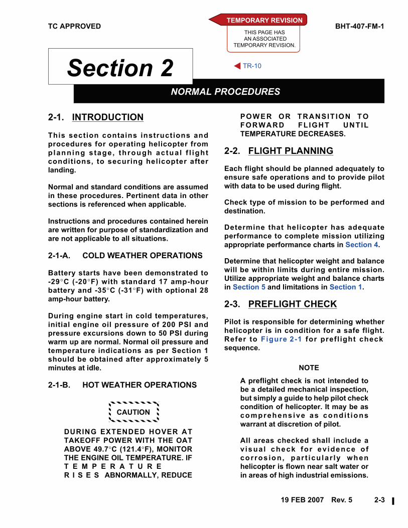
22-1. INTRODUCTION
This section contains instructions and
procedures for operating helicopter from
planning s tage , through actua l f l ight
conditions, to securing helicopter after
landing.
Normal and standard conditions are assumed
in these procedures. Pertinent data in other
sections is referenced when applicable.
Instructions and procedures contained herein
are written for purpose of standardization and
are not applicable to all situations.
2-1-A. COLD WEATHER OPERATIONS
Battery starts have been demonstrated to
-29°C (-20°F) with standard 17 amp-hour
battery and -35°C (-31°F) with optional 28
amp-hour battery.
During engine start in cold temperatures,
initial engine oil pressure of 200 PSI and
pressure excursions down to 50 PSI during
warm up are normal. Normal oil pressure and
temperature indications as per Section 1
should be obtained after approximately 5
minutes at idle.
2-1-B. HOT WEATHER OPERATIONS
CAUTION
DURING EXTENDED HOVER AT
TAKEOFF POWER WITH THE OAT
ABOVE 49.7°C (121.4°F), MONITOR
THE ENGINE OIL TEMPERATURE. IF
T E M P E R A T U R E
R I S E S ABNORMALLY, REDUCE
POWER OR TRANSIT ION TO
FORWARD FLIGHT UNTIL
TEMPERATURE DECREASES.
2-2. FLIGHT PLANNING
Each flight should be planned adequately to
ensure safe operations and to provide pilot
with data to be used during flight.
Check type of mission to be performed and
destination.
Determine that helicopter has adequate
performance to complete mission utilizing
appropriate performance charts in Section 4.
Determine that helicopter weight and balance
will be within limits during entire mission.
Utilize appropriate weight and balance charts
in Section 5 and limitations in Section 1.
2-3. PREFLIGHT CHECK
Pilot is responsible for determining whether
helicopter is in condition for a safe flight.
Refer to Figure 2-1 for prefl ight check
sequence.
NOTE
A preflight check is not intended to
be a detailed mechanical inspection,
but simply a guide to help pilot check
condition of helicopter. It may be as
comprehens ive as condi t ions
warrant at discretion of pilot.
All areas checked shall include a
v isua l check for ev idence of
corros ion, par t icu lar ly when
helicopter is flown near salt water or
in areas of high industrial emissions.
TEMPORARY REVISION
THIS PAGE HAS
AN ASSOCIATED
TEMPORARY REVISION.
TR-10
BHT-407-FM-1 TC APPROVED
2-4———Rev. 5—19 FEB 2007
2-3-A. BEFORE EXTERIOR CHECK
1. Flight planning — Completed.
2. Publications — Checked.
3. GW and CG — Computed.
4. Helicopter servicing — Completed.
5. Battery — Connected.
2-3-B. EXTERIOR CHECK
2-3-B-1. FUSELAGE — CABIN RIGHT SIDE
WARNING
FAILURE TO REMOVE ROTOR
T I E D O W N S B E F O R E E N G I N E
STARTING MAY RESULT IN SEVERE
DAMAGE AND POSSIBLE INJURY.
1. All main rotor blades — Tiedowns
removed, condition.
2. Right static port — Condition.
3. Cabin doors and hinge bolts —
Condition and security.
4. Windows — Condition and security.
5. Landing gear — Condition. Ground
handling wheel removed.
6. Forward and aft crosstube fairings (if
installed) — Secured, condition, and
aligned.
2-3-B-2. FUSELAGE — CENTER RIGHT
SIDE
1. Engine inlet — Condition; remove
inlet covers.
2. Cabin roof, transmission cowling,
and engine air inlet area — Cleaned
of all debris, accumulated snow and
ice; cowling secured.
3. Forward fairing — Secured.
4. Transmission — Check oil level.
Verify actual presence of oil in sight
gauge.
5. Transmission oil cooler lines —
Condition and security.
6. Transmission mounts — Condition
and security.
7. Main driveshaft — Condition.
8. Access door — Secured.
9. Fuel filler cap — Visually check fuel
level and cap secured.
NOTE
If helicopter is not parked on a level
surface, fuel sump may not properly
drain contaminants.
10. Fuel sump — Drain fuel sample as
follows:
a. RIGHT and LEFT FUEL BOOST/
XFR circuit breaker switches —
OFF.
b. BATT switch — BATT (on).
c. FUEL VALVE switch — OFF.
d. FWD and AFT FUEL SUMP drain
buttons — Press, drain sample,
then release.
11. Airframe fuel filter — Drain and
check before first flight of day as
follows:
a. RIGHT and LEFT FUEL BOOST/
XFR circuit breaker switches —
LEFT and RIGHT (on).
b. FUEL VALVE switch — ON.
c. Fuel filter drain valve — Open,
drain sample, then close.
12. Fuel filter test switch — Press and
check FUEL FILTER caution light
illuminates. Release switch and
check light extinguishes.

TC APPROVED BHT-407-FM-1
19 FEB 2007—Rev. 5———2-5
13. FUEL VALVE switch — OFF.
14. LEFT and RIGHT FUEL BOOST/XFR
circuit breaker switches — OFF.
15. BATT switch — OFF.
16. Power plant area:
a. Main driveshaft aft flexure —
Condition.
b. Engine — Condition, security of
attachments, evidence of oil
leakage.
c. Engine mounts — Condition and
security.
d. Throttle linkage — Condition,
security, and freedom of
operation.
e. Engine fuel pump — Security
and condition, evidence of
leakage.
f. Hydromechanical unit —
Security and condition,
evidence of leakage.
g. Hoses and tubing — Chafing,
security, and condition.
17. Engine cowl — Secured.
18. Generator cooling scoop — Clear of
debris.
19. Oil tank — Leaks, security, and cap
secured.
20. Access door — Secured.
21. Aft fairing — Secured.
2-3-B-3. FUSELAGE — AFT RIGHT SIDE
1. Fuselage — Condition.
2. Tail rotor driveshaft cover —
Condition and security.
3. Tailboom — Condition.
4. Horizontal stabilizer and position
light — Condition and security.
2-3-B-4. FUSELAGE — FULL AFT
1. Vertical fin — Condition.
2. Tail rotor guard — Condition and
security.
3. Anticollision light — Condition and
security of lens.
4. Aft position light — Condition.
5. Tail rotor gearbox — Oil level, leaks
and security.
6. Tail rotor — Tiedown removed,
condition and free movement.
7. Tail rotor controls — Condition and
security.
8. Tail rotor blades:
a. General condition.
b. Tip block — Security and seal
integrity.
c. Internal blade root — Clear of
snow and ice.
9. Tail rotor yoke — Condition,
evidence of static stop contact
damage (deformed static stop yield
indicator).
2-3-B-5. FUSELAGE — AFT LEFT SIDE
1. Tailboom — Condition.
2. Tail rotor driveshaft cover —
Condition and security.
3. Horizontal stabilizer area:
a. Horizontal stabilizer — General
condition and security of
attachment.
b. Position light — Condition and
security.
c. Forward and aft section of left
upper stabilizer support to
tailboom area — Condition of
tailboom.
TEMPORARY REVISION
THIS PAGE HAS
AN ASSOCIATED
TEMPORARY REVISION.
TR-10
BHT-407-FM-1 TC APPROVED
2-6———Rev. 5—19 FEB 2007
4. Fuselage — Condition.
5. Forward tail rotor driveshaft
coupling — Condition of splined
adapter.
6. Oil cooler blower shaft hanger
bearings — Evidence of grease
leakage and overheating.
7. Oil cooler blower — Clear of
obstructions and condition.
8. Oil cooler — Condition and leaks.
9. Oil cooler blower access door —
Secured.
10. Oil tank sight glass — Check oil level.
11. Aft fairing — Secured.
12. Baggage compartment — Cargo tied
down, door secured.
13. Exhaust cover — Removed.
14. Power plant area:
a. Engine — Condition, security of
attachments.
b. Engine mounts — Condition and
security.
c. Exhaust stack — Condition and
security.
d. Evidence of fuel and oil leaks.
e. Fuel and oil filter bypass
indicators — Check retracted.
f. Hoses and tubing for chafing
and condition.
g. Pneumatic lines — Condition
and security.
h. Tail rotor driveshaft —
Condition of splines and
couplings.
i. Air induction diffuser duct —
Condition and security.
j. Rotor brake disc and caliper (if
installed) — Condition, security
of attachment and leakage.
Ensure brake pads are retracted
from brake disc.
k. Engine cowling — Secured.
l. Air induction cowling —
Secured.
m. Cabin roof, transmission
cowling, engine air inlet area,
and plenum — Clear of all
debris, accumulated snow and
ice; cowling secured.
15. Transmission area:
a. Transmission mounts —
Condition and security of
elastomeric mounts.
b. Transmission oil filter — Ensure
bypass indicator not extended.
c. Main driveshaft — Condition.
d. Transducers and pressure lines
— Condition and security.
e. Access door — Secured.
2-3-B-6. CABIN ROOF
1. Main rotor dampers and fairing —
Condition and security.
2. Main rotor hub, yoke and frahm —
Condition and security.
3. Main rotor blade and skin —
Condition.
4. Pitch horn bearing — Wear and
security.
5. Main rotor pitch links — Condition
and security of attachment bolts and
locking hardware.
6. Swashplate assembly — Condition,
security of attached controls, and
boot condition.
TEMPORARY REVISION
THIS PAGE HAS
AN ASSOCIATED
TEMPORARY REVISION.
TR-10
TC APPROVED BHT-407-FM-1
19 FEB 2007—Rev. 5———2-7
7. Control linkages to swashplate —
Condition, security of attachment
bolts and locking hardware.
8. Control tube hydraulics-off balance
springs — Condition and security.
9. Hydraulic reservoir filler cap —
Closed and locked.
10. Hydraulic system filters — Bypass
indicator retracted.
11. Hydraulic actuators and lines —
Condition, security, interference,
leakage.
2-3-B-7. FUSELAGE — CABIN LEFT SIDE
1. Forward fairing and access door —
Secured.
2. Cabin doors and hinge bolts —
Condition and security.
3. Windows — Condition and security.
4. Hydraulic reservoir — Check fluid
level.
5. Landing gear — Condition and
ground handling wheel removed.
6. Forward and aft crosstube fairings (if
installed) — Secured, condition, and
aligned.
7. Left static port — Condition.
2-3-B-8. FUSELAGE — FRONT
1. Exterior surfaces — Condition.
2. Windshield — Condition and
cleanliness.
3. Battery and vent lines — Condition
and security.
4. HOUR METER circuit breaker — In.
5. Battery access door — Secured.
6. Pitot tube — Cover removed, clear of
obstructions.
7. External power door — Condition
and security.
8. Landing light lamps — Condition.
9. Antennas — Condition and security.
2-4. INTERIOR AND PRESTARTCHECK
1. Cabin interior — Clean, equipment
secured.
2. Fire extinguisher — Installed and
secured.
3. Cabin loading — Maintain CG within
limits.
4. Passenger seat belts — Secured.
5. Copilot seat belt — Secured (if solo).
6. Doors — Secured.
7. Throttle — Closed.
8. LDG LTS switch — OFF.
9. Communications switches — Set.
10. Altimeter — Set.
11. Instruments — Correct indications.
12. Overhead switches — Set:
a. BATT switch — OFF.
b. GEN switch — OFF.
c. PART SEP switch (if installed) —
OFF.
d. ANTI COLL LT switch — ANTI
COLL LT (on).
e. HYD SYS switch — HYD SYS
(on).
f. CABIN LT/PASS switch — OFF.
g. POS LT switch — As desired.
h. DEFOG switch — OFF.
i. PITOT HEATER switch — OFF.

BHT-407-FM-1 TC APPROVED
2-8———Rev. 7—30 JUL 2008
j. ENG ANTI ICE switch — OFF.
k. AVIONICS MASTER switch —
OFF.
l. HEATER switch (if installed) —
OFF.
m. INSTR LT rheostat — OFF.
13. Overhead circuit breaker switches —
OFF.
14. Overhead circuit breakers — In.
15. Rotor brake handle (if installed) — Up
and latched.
CAUTION
28 VDC GPU SHALL BE 500
AMPERES OR LESS TO REDUCE
RISK OF STARTER DAMAGE FROM
OVERHEATING.
16. GPU — Connected (if used).
17. BATT switch — ON for battery start,
ON for GPU start, OFF for battery cart
start. Observe the following:
a. Low rotor audio horn activated.
NOTE
With “Ah lers” NR/NP gauge
installed, NR/NP needles do not self
test.
b. For 8 seconds,
(1) Trend arcs on LCD
instruments indicate full
scale.
(2) TORQUE and NG digits
display 8188.8.
(3) MGT and FUEL digits
display 81888.
(4) NR and NP needles move to
107% and 100%,
respectively.
c. After 3 seconds; ENG OUT,
FADEC DEGRADE, FADEC
FAULT, RESTART FAULT, and
ENGINE OVSPD lights
illuminate with activation of
engine out audio for 3 seconds.
d. ENG OUT light re-illuminates
with reactivation of engine out
audio, after 3 seconds.
18. HORN MUTE button — Press to mute.
19. Caution lights — ENG OUT, XMSN
OIL PRESS, RPM, HYDRAULIC
SYSTEM, GEN FAIL, L/FUEL BOOST,
R/FUEL BOOST, L/FUEL XFR, and R/
FUEL XFR will be illuminated.
NOTE
L/FUEL XFR and R/FUEL XFR will not
be illuminated when forward fuel
tank is empty.
20. PEDAL STOP PTT switch
annunciator:
Pedals — Centered.
Press — Verify PEDAL STOP caution
and ENGAGED annunciator
illuminated and left pedal travel
restricted.
Release — Verify PEDAL STOP
caution and ENGAGED annunciator
extinguished and both pedals travel
unrestricted.
21. Flight controls — Loosen frictions;
check travel and verify CYCLIC
CENTERING light operation; position
for start. Tighten friction as desired.
22. Throttle — Check freedom of travel
and appropriate operation at OFF, I
(idle), FLY and MAX positions.
Return throttle to OFF position.
NOTE
With INSTR LT rheostat on and CAUT
LT switch positioned to DIM, caution
TC APPROVED BHT-407-FM-1
30 JUL 2008—Rev. 7———2-9
lights are dimmed to a fixed intensity
and cannot be adjusted by INSTR LT
rheostat.
23. INSTR LT rheostat — As desired.
24. CAUT LT switch — As desired.
25. FUEL BOOST/XFR circuit breaker
switches — LEFT (on) and RIGHT
(on) and verify all boost and transfer
caution lights extinguish.
26. FUEL pressure — Check.
27. CAUTION LT TEST button — Press to
test.
28. INSTR CHK button — Press and
check for exceedances.
29. LCD TEST button — Press to test, if
desired.
30. FADEC HORN TEST button — Press
to test.
31. FADEC MODE switch — AUTO.
32. FUEL VALVE switch — ON, guard
closed, FUEL VALVE light
illuminates then extinguishes.
33. FUEL QTY — Check TOTAL and FWD
tank quantity.
34. OAT/VOLTS display — Check OAT
and select VOLTS.
CAUTION
ANY ATTEMPT TO START ENGINE
WHEN VOLTAGE IS BELOW 24
VOLTS MAY RESULT IN A HOT
START. MONITOR FOR FADEC
FAILURE. IF FADEC FAILS (FADEC
FAIL WARNING LIGHT), ABORT
START BY ROLLING THROTTLE TO
CUTOFF AND ENGAGE STARTER
TO REDUCE MGT.
2-5. ENGINE START
1. Collective — Full down.
2. Cyclic and pedals — Centered and
CYCLIC CENTERING light
extinguished.
NOTE
If throttle is positioned in idle for
more than 60 seconds, starter
latching is disabled and throttle must
be repositioned to cut off and then
back to idle to enable it for another 60
seconds.
It is recommended that MGT be
below 150°C when below 10,000 feet
HP or below 65 °C when above 10,000
feet HP prior to attempting an engine
sta r t . Compl iance w i th th is
recommendation will allow for cooler
starts and reduce potentia l of
reaching hot start abort limits. Refer
to DRY MOTORING RUN, paragraph
2-5-A.
3. Throttle — Idle position.
4. START switch — Momentarily press
(hold for approximately 1 second)
and observe START and AUTO
RELIGHT lights are illuminated.
5. MGT — Monitor.
CAUTION
IF MAIN ROTOR IS NOT ROTATING
BY 25% NG, ABORT START BY
ROLLING THROTTLE TO CUTOFF.
ENSURE STARTER HAS
DISENGAGED WHEN MGT
DECREASES BELOW 150°C.
6. START light — Extinguished at 50%
NG (starter has disengaged).
7. AUTO RELIGHT light — Extinguished
at 60% NG.
8. ENG and XMSN OIL pressures —
Check.
TEMPORARY REVISION
THIS PAGE HAS
AN ASSOCIATED
TEMPORARY REVISION.
TR-11
BHT-407-FM-1 TC APPROVED
2-10———Rev. 5—19 FEB 2007
CAUTION
IF ENGINE HAS BEEN SHUT DOWN
FOR MORE THAN 15 MINUTES,
STABILIZE AT IDLE FOR 1 MINUTE
BEFORE INCREASING THROTTLE.
NOTE
During cold temperature operations,
normal transmission and engine oil
pressure limits may be exceeded
during start. Stabilize engine at idle
until minimum temperature and
pressure limits are attained.
9. Idle — 63 ±1% NG.
10. BATT switch — ON (if applicable).
11. GPU — Disconnect and close door (if
applicable).
12. GEN switch — GEN (on); observe
GEN FAIL light extinguishes.
NOTE
Turn generator OFF if ammeter
indication drops to zero amps after
an initial full scale indication. One
reset is allowed. RESET generator
and then turn generator back ON
(applicable with AMPS/FUEL PSI
gauge PN 407-075-024-101 and sub.).
Refer to BHT-407-MD-1.
13. Voltmeter — 28.5 ±0.5 volts.
14. FLIGHT INSTR circuit breaker
switches (3) (if installed) — DG, ATT
and TURN (on).
NOTE
If dual controls are installed, guard
throttle to prevent inadvertent
manipulation from co-pilot position.
2-5-A. DRY MOTORING RUN
The following procedure is used to reduce
residual MGT to recommended levels for
engine start.
1. Throttle — Closed position.
2. START switch — Hold engaged for 15
seconds, then release.
Follow ENGINE START procedure, paragraph
2-5, once 0% NG is indicated.
2-5-B. ALTERNATE ENGINE START
This procedure may be used in hot and/or
high altitude environment where aborted hot
starts have been experienced and when prior
troubleshooting has not revealed any engine
maintenance issues.
1. Collective — Full down.
2. Cyclic and pedals — Centered and
CYCLIC CENTERING light
extinguished.
NOTE
It is recommended that MGT be
below 150°C when below 10,000 feet
HP or below 65°C when above 10,000
feet HP prior to attempting an engine
sta r t . Compl iance w i th th is
recommendation will allow for cooler
starts and reduce potentia l of
reaching hot start abort limits. Refer
to DRY MOTORING RUN, paragraph
2-5-A.
3. Throttle — Closed position.
4. START switch — Hold engaged and
observe START and AUTO RELIGHT
lights are illuminated.
a. Throttle — Open to IDLE at
approximately 16% NG.
5. MGT — Monitor.
TC APPROVED BHT-407-FM-1
19 FEB 2007—Rev. 5———2-11
NOTE
Engine will detect l ight off and
smoothly accelerate to idle while
limiting MGT, if necessary.
a. START switch — Once light off
is detected, release.
CAUTION
IF MAIN ROTOR IS NOT ROTATING
BY 25% NG, ABORT START BY
ROLLING THROTTLE TO CUTOFF.
ENSURE STARTER HAS
DISENGAGED WHEN MGT
DECREASES BELOW 150°C.
6. START light — Extinguished at 50%
NG (starter has disengaged).
7. AUTO RELIGHT light — Extinguished
at 60% NG.
8. ENG and XMSN OIL pressures —
Check.
CAUTION
IF ENGINE HAS BEEN SHUT DOWN
FOR MORE THAN 15 MINUTES,
STABILIZE AT IDLE FOR 1 MINUTE
BEFORE INCREASING THROTTLE.
NOTE
During cold temperature operations,
normal transmission and engine oil
pressure limits may be exceeded
during start. Stabilize engine at idle
until minimum temperature and
pressure limits are attained.
9. Idle — 63 ±1% NG.
10. BATT switch — ON (if applicable).
11. GPU — Disconnect and close door (if
applicable).
12. GEN switch — GEN (on); observe
GEN FAIL light extinguishes.
NOTE
Turn generator OFF if ammeter
indication drops to zero amps after
an initial full scale indication. One
reset is allowed. RESET generator
and then turn generator back ON
(applicable with AMPS/FUEL PSI
gauge PN 407-075-024-101 and
subsequent). Refer to BHT-407-MD-1.
13. Voltmeter — 28.5 ±0.5 volts.
14. FLIGHT INSTR circuit breaker
switches (3) (if installed) — DG, ATT
and TURN (on).
NOTE
If dual controls are installed, guard
thrott le to prevent inadvertent
manipulation from co-pilot position.
2-6. SYSTEMS CHECK
2-6-A. PRELIMINARY HYDRAULICSYSTEMS CHECK
NOTE
Uncommanded control movement or
motoring with hydraulic system off
may indicate hydraulic system
malfunction.
1. HYD SYS switch — OFF.
2. HYDRAULIC SYSTEM caution light
— Illuminated.
3. HYD SYS switch — HYD SYS (on).
4. HYDRAULIC SYSTEM caution light
— Extinguished.
BHT-407-FM-1 TC APPROVED
2-12———Rev. 6—20 JUN 2007
2-6-B. FADEC MANUAL CHECK
WARNING
A U T O T O M A N U A L M O D E
TRANSITIONS WITH NR/NP AT 100%
FLAT PITCH CAN RESULT IN RAPID
N R / N P A C C E L E R A T I O N I N
APPROXIMATELY 7 SECONDS. TO
AVOID POSSIBLE OVERSPEED
C O N D I T I O N , P E R F O R M T H E
FOLLOWING CHECK AT IDLE (63%
NG).
1. Throttle — Idle (63% NG).
2. FADEC MODE switch — MAN.
3. FADEC MANUAL and AUTO
RELIGHT lights — Illuminated.
4. Check NG stabilized at 75% or less.
5. Throttle — Increase slowly to ensure
engine responds, then return to idle.
6. FADEC MODE switch - AUTO.
7. FADEC MANUAL and AUTO
RELIGHT lights — Extinguished.
2-6-C. ENGINE RUNUP
CAUTION
FAILURE TO SMOOTHLY
TRANSITION THE THROTTLE FROM
THE GROUND IDLE POSITION TO
THE FLY POSITION, MAINTAINING
TORQUE LESS THAN 40% MAY
RESULT IN ENGINE OVERSPEED OR
OVERTORQUE.
1. Throttle — Increase smoothly to FLY
detent position while maintaining
torque below 40%. Check RPM
warning light extinguished at 95%
NR.
2. NR and NP needles — Check
matching and indicating 100%.
NOTE
Overhead c i rcu i t breakers
highlighted with arrow graphic ;
are powered through AVIONICS
MASTER switch.
3. AVIONICS MASTER switch —
AVIONICS MASTER (on).
4. ELT (if installed) — Check for
inadvertent transmission.
5. Flight controls — Check freedom
with minimum friction.
6. ENG ANTI ICE switch — ENG ANTI
ICE (on); check for MGT increase and
illumination of ENGINE ANTI-ICE
light (if installed).
7. ENG ANTI ICE switch — OFF; check
MGT returns to normal and ENGINE
ANTI-ICE light (if installed)
extinguishes; then ENG ANTI ICE
(on) if required.
NOTE
If temperature is below 5°C (40°F)
and visible moisture is present, ENG
ANTI ICE shall be on.
8. PART SEP switch (if installed) — As
required.
2-6-D. HYDRAULIC SYSTEMS CHECK
NOTE
Hydraulic systems check is to
determine proper operat ion of
hydraulic actuators for each flight
control system. If abnormal forces,
unequal forces, control binding, or
motoring are encountered, it may be
an indication of a malfunctioning
flight control actuator.
1. Collective — Full down.
TC APPROVED BHT-407-FM-1
20 JUN 2007—Rev. 6———2-13
2. NR — 100% RPM.
3. HYD SYS switch — OFF.
4. HYDRAULIC SYSTEM caution light
— Illuminated.
5. Cyclic — Centered.
6. Cyclic control — Check normal
operation by moving cyclic forward
and aft, then left and right
(approximately 1 inch). Center cyclic.
7. Collective — Check normal
operation by increasing collective
slightly (1 to 2 inches). Repeat two to
three times as required. Return to full
down position.
8. Pedals — Check normal operation by
displacing pedals slightly (1 inch).
9. HYD SYS switch — HYD SYS (on).
10. HYDRAULIC SYSTEM caution light
— Extinguished.
11. Cyclic and collective friction — Set
as desired.
2-7. BEFORE TAKEOFF
1. ENG ANTI ICE switch — As required.
2. Light switches — As required.
3. INSTR LT rheostat — As desired.
NOTE
For night flight, it is recommended to
point the map light at the flight
inst ruments and set to a low
intensity. Sufficient night lighting will
be provided in the event of an
instrument lighting failure.
4. Radio(s) — Check as required.
5. Flight controls — Position and adjust
frictions for takeoff.
CAUTION
F A I L U R E T O P O S I T I O N A N D
MAINTAIN THROTTLE IN FLY
DETENT POSIT ION PRIOR TO
TAKEOFF AND DURING NORMAL
FL I GHT OPERATIONS CAN LIMIT
AVAILABLE ENGINE POWER.
6. Throttle — Open to FLY detent
position. Check 99 to 100% NR/NP.
7. Engine, transmission, and electrical
instruments — Within limits.
8. Flight and navigation instruments —
Check.
9. FUEL QTY — Note indication.
10. FUEL QTY FWD TANK button —
Press, note fuel remaining in forward
cell.
2-8. TAKEOFF
1. Rear facing seat headrests —
Adjusted to proper position.
NOTE
During takeoffs disregard CYCLIC
CENTERING light and position cyclic
as required.
2. Collective — Increase to hover.
3. Directional control — As required to
maintain desired heading.
4. Cyclic — Apply as required to
accelerate smoothly.
5. Increase collective, up to 5% torque
above hover power, to obtain desired
rate of climb and airspeed. Once
clear of the HV diagram shaded
areas, adjust power and airspeed as
desired.
BHT-407-FM-1 TC APPROVED
2-14———Rev. 6—20 JUN 2007
6. PEDAL STOP PTT switch — Check
ENGAGED annunciator illuminated
above 55 ±5 KIAS.
2-9. IN-FLIGHT OPERATIONS
1. AIRSPEED — As desired (not to
exceed VNE at flight altitude).
CAUTION
A T H I G H P O W E R A N D H I G H
A I R S P E E D , C Y C L I C O N L Y
A C C E L E R A T I O N S A N D
MANEUVERING MAY
SIGNIFICANTLY INCREASE MGT
AND TORQUE WITH NO
COLLECTIVE INPUT. TH IS
INCREASE IS MORE RAPID AT
LOWER OAT.
NOTE
Pilot shall keep feet on tail rotor
pedals at all times. Do not press
PEDAL STOP PTT switch in flight.
2. PEDAL STOP PTT switch — Check
ENGAGED annunciator illuminated
above 55 ±5 KIAS.
3. ENG ANTI ICE and PITOT HEATER
switches — ENG ANTI ICE and PITOT
HEATER switches on in visible
moisture when ambient temperature
is at or below 5°C (40°F).
4. PITOT HEATER — Confirm operation
(increase ammeter load).
NOTE
When ENG ANTI ICE switch is in ENG
ANTI ICE (on), MGT will increase.
Monitor MGT when selecting ENG
ANTI ICE at high power settings.
5. Altimeter — Within limits.
6. FUEL QTY FWD TANK button —
Press, note forward fuel tank
indication.
NOTE
Full forward fuel tank quanti ty
(approximately 256 pounds) will be
indicated at approximately 770
pounds or greater total fuel. Fuel
t ransfer w i l l be complete a t
approximately 195 pounds total fuel.
2-10. DESCENT AND LANDING
NOTE
Large reductions in collective pitch
at heavy GW may permit NR to
increase independent of NP (needles
split). Main rotor may be reengaged
with a smooth increase in collective
pitch.
1. Rear facing seat headrests —
Adjusted to proper position.
2. Flight controls — Adjust friction as
desired.
3. Throttle — Fly detent position. Check
99 to 100% NP.
4. Flight path — As required for type of
approach.
5. ENG ANTI ICE — As required.
6. LDG LTS switch — As desired.
NOTE
During run-on or slope landings,
disregard CYCLIC CENTERING light
and position cyclic as required. After
landing is completed and collective
is full down, reposition cyclic so that
CYCLIC CENTERING l ight is
extinguished.
7. PEDAL STOP PTT switch — Check
ENGAGED annunciator extinguished
below 50 ±5 KIAS.
TC APPROVED BHT-407-FM-1
20 JUN 2007—Rev. 6———2-15
2-11. ENGINE SHUTDOWN
1. Collective — Full down.
2. Cyclic and pedals — Centered and
CYCLIC CENTERING light
extinguished.
3. Cyclic friction — Increase so that
cyclic maintains centered position.
4. LDG LTS switch — OFF.
5. Throttle — Reduce to idle stop.
Check RPM warning light illuminated
and audio on at 95% NR.
NOTE
If dual controls are installed, guard
throttle to prevent inadvertent
manipulation from co-pilot position.
6. HORN MUTE button — Press to mute.
7. MGT — Stabilize at idle for 2 minutes.
8. ENG ANTI ICE switch — OFF.
9. FLIGHT INSTR circuit breakers
switches (if installed) — OFF.
10. FUEL BOOST/XFR LEFT circuit
breaker switch — OFF.
NOTE
Left fuel boost and transfer pumps
will continue to operate until either
LEFT FUEL BOOST/XFR circuit
breaker switch (highlighted with
yellow border) or FUEL VALVE
switch is positioned to OFF. These
pumps operate directly from battery
and will not be deactivated when
BATT switch is OFF. Battery power
will be depleted if both switches
remain on.
11. ELT (if installed) — Check for
inadvertent transmission.
12. AVIONICS MASTER switch — OFF.
13. GEN switch — OFF.
14. OVSPD TEST button — If required;
press, hold 1 second, and release.
NOTE
Overspeed shutdown test should be
accompl ished on f i rs t eng ine
shutdown of the day . ENGINE
OVSPD l ight wi l l momentar i ly
illuminate in addition to those lights
that il luminate during a normal
shutdown.
15. IDLE REL switch — Press and hold.
CAUTION
POSITIONING THROTTLE OUT OF
CUT-OFF DURING NG SPOOL DOWN
MAY CAUSE POST ENGINE
SHUTDOWN FIRE.
16. Throttle — Closed; check MGT and
NG decreasing, ENGINE OUT
warning light illuminated and audio
on at 55 ±1%.
17. HORN MUTE button — Press to mute.
CAUTION
AVOID RAPID ENGAGEMENT OF
ROTOR BRAKE IF HELICOPTER IS
ON ICE OR OTHER SLIPPERY OR
LOOSE SURFACE TO PREVENT
ROTATION OF HELICOPTER.
18. Rotor brake (if installed) — Apply full
rotor brake at or below 40% NR.
Return rotor brake handle to stowed
position just prior to main rotor
stopping.
19. FUEL VALVE switch — OFF.
BHT-407-FM-1 TC APPROVED
2-16———Rev. 7—30 JUL 2008
CAUTION
DO NOT INCREASE COLLECTIVE OR
APPLY LEFT TAIL ROTOR PEDAL
TO SLOW ROTOR DURING
COASTDOWN.
20. Pilot — Remain on flight controls
until rotor has come to a complete
stop.
21. All overhead switches, except HYD
SYS switch — OFF.
NOTE
Ensure engine ro ta t ion has
complete ly s topped pr io r to
positioning BATT switch to OFF.
22. BATT switch — OFF, with NG at 0%.
CAUTION
APPLICABLE MAINTENANCE
ACTION MUST BE PERFORMED
PRIOR TO FURTHER FLIGHT IF A
FADEC LIGHT HAS ILLUMINATED
DURING THE PREVIOUS FLIGHT OR
ON ENGINE SHUTDOWN.
NOTE
If shutting down at, or refueling to,
between approximately 195 to 213
pounds total fuel quantity, up to 18
pounds of fuel may remain in forward
fuel cell as unusable.
2-12. POSTFLIGHT CHECK
If any of following conditions exist:
• Thunderstorms are in local area or
forecasted.
• Winds in excess of 35 knots or a
gust spread of 15 knots exists or is
forecasted.
• Helicopter is parked within 150 feet
of hovering or taxiing aircraft that
are in excess of basic GW of
helicopter.
• Helicopter to be left unattended.
Perform following:
1. Install main rotor blade tie-downs.
2. Secure tail rotor loosely to tailboom
with tie-down strap to prevent
excessive flapping.
3. Install exhaust cover, engine inlet
protective plugs and pitot cover.
NOTE
Refer to BHT-407-MD-1 for additional
tie-down data.
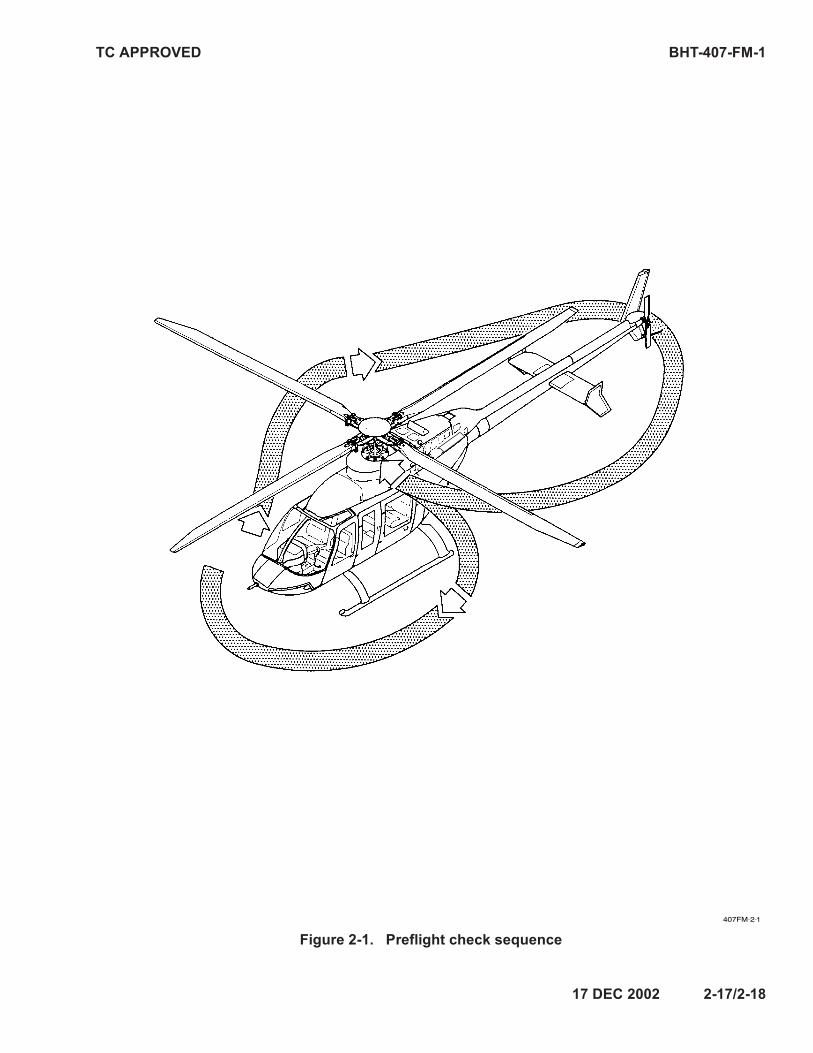
TC APPROVED BHT-407-FM-1
Figure 2-1. Preflight check sequence
17 DEC 2002 2-17/2-18


![§4. Limitations on the Speaker’s Powers · PDF fileLimitations on the Speaker’s Powers As previously noted, ... topic in advance of its delivery; ... [of Mis-sissippi]: Mr. Speaker,](https://img.pdfslide.us/doc/110x75/5aae14f77f8b9a3a038bb9ed/4-limitations-on-the-speakers-powers-on-the-speakers-powers-as-previously.jpg)