Embed Size (px)
Citation preview
Limit Cycle Oscillation on Control Surfaces Due to Freeplay
Wolfgang G. Luber
European Aeronautic Defence and Space Company Military Air System MEG
85070 Manching, Germany Phone: +49-8459-81-78578
Fax: +49-8459-81-78583 E-mail: [email protected]
Abstract This paper presents the results of an analytical effort conducted to determine the effects of freeplay on aerodynamic and control surfaces on the flutter mechanism and their associated LCO.. The investigation was made on a multi role combat aircraft with a backward sweepable wing (freeplay in yaw), conventional vertical tail (freeplay between fin and rudder) and an all movable taileron (freeplay in pitch, roll and yaw). Findings from ground tests, like freeplay measurements are presented and an explanation for these test results are given. Calculations with equivalentr stiffness assumptions and parameter variations have been performed to show the LCO trend. An harmonic balance method is used to determine the reduced stiffness parameters due to freeplay.A procedure for determining the LCO is presented. With the results of ground testing and the harmonic balance method LCO and flutter calculations have been performed by separate variations of the theoretical actuator stiffness of the two control surfaces. Sub and supersonic flutter/LCO calculations show the influence of stiffness reduction due to freeplay. The analysis indicate that the reduction of stiffness as a result of friction or freeplay could have detrimental effects on flutter stability in the control surface rotation mode. Military requirements state that aircraft must be free of flutter up to 115 percent of the design limit speed and that the freeplay in bearings of control surfaces must not exceed limitations. In service measurements of freeplay are very seldom, therefore a reliable flutter/LCO prediction have to performed to show that no LCO/Flutter will be induced over the design flight envelop.
1. Introduction
Fighter airplanes like the variable sweep wing combat aircraft TORNADO using high power control and automatic control systems, which basically are designed to manoeuvre the aircraft and to provide sufficient damping for the rigid body modes. The airplane, Figure 1 in this study is controlled by a triplex analogue fly-by-wire flight control system, mechanical emergency control and automatic stabilisation. The primary flight control systems provides pitch, roll and yaw control by means of
wing mounted spoilers limited to low speed conditions, an all moving taileron and a conventional rudder. The control surfaces are powered by high sophisticated actuators and the fly by wire technology requires more and more analytical investigation in view of stability of the hydraulic system itself either in low and high frequency range. Aeroservoelastic investigations must prove that the actuator including the hydraulic system is stable over the complete flight envelope. Beside the stability requirements the system must be able to fulfil the specified minimum stiffness on the control surface attachments. The stiffness of the actuators
RTO-MP-AVT-152 18 - 1
UNCLASSIFIED/UNLIMITED
UNCLASSIFIED/UNLIMITED

will be changed over the working frequency. Measurements of freeplay (or freeplay in the American literature) are very seldom and costly on aircraft in service.
Figure 1: Two sides Aircraft view
Stiffness will be also reduced of the actuator and its linking mechanism on the aircraft structure due to the freeplay in bearings and connection points. This investigation shown in this paper was done during flight expansion, because the measurement on different prototype aircraft revealed some exceedances in the specified freeplay. 2. Structural Design Requirements The full requirements of the specification are subjected to the MIL-A-8870C, Airplane strength and rigidity Vibration, Flutter, and Divergence. 2.1 Aeroelastic stability Analyses, wind tunnel tests, and airplane ground and flight tests up to design limit speeds shall demonstrate that flutter, divergence and other related aeroelastic or aeroservoelastic instability boundaries occur outside the 1.15 times design limit
speed envelope. The aircraft shall meet the following stability design requirements for both normal and emergency conditions. • Margin: Fifteen percent equivalent airspeed
margin on the applicable design limit speed envelope, both at constant altitude and constant Mach number.
• Damping: The damping coefficient g (structural damping) for any critical flutter mode or for any significant dynamic response mode shall be at least three percent for all altitudes on flight speeds up to design limit speed.
2.2 Freeplay of control surfaces and tabs Detailed design shall assure that normal wear of components, of control surfaces and tabs, and actuating systems will not result in values of freeplay exceeding those specified below throughout the service life of the airplane. Components having an adequately established wear life may be replaced at scheduled intervals as approved by the contracting activity. However, all replacement shall be included in the wear out replacement budget established for the overall airplane. • For a trailing edge control surface which extends
outboard of the 75 percent span station of main surface, the total freeplay shall not exceed 0.13° or 0.0022 rad.
• For an all-movable control surface, the total freeplay shall not exceed 0.034° or 0.0006 rad.
• For wing fold, the total freeplay shall not exceed 0.25° or 0.0044 rad.
3. Actuator Stiffness Modern actuators today contain up to four electronically systems and two hydraulic systems. In the closed system, back up structure reduces the stiffness of the actuator due to the in series connections. Unexpected failures of the electrical and or the hydraulic and or the mechanical systems reduce the stiffness substantially. Figure 2 shows a typical impedance measurement of an actuator with two hydraulic systems. Failures in the electrical system reduces only the stiffness insight the allowable tolerances. This figure depicts that at a frequency of about 20 Hz a stiffness reduction of about 30% will be happened if one hydraulic system is out of order.
Limit Cycle Oscillation on Control Surfaces Due to Freeplay
18 - 2 RTO-MP-AVT-152
UNCLASSIFIED/UNLIMITED
UNCLASSIFIED/UNLIMITED

20 30 40 50 60 70 80 90 100
-70
-60
-50
-40
-30
-20
-10
0
10
20
5 Hz
10 Hz
15 Hz
20 Hz25 Hz 30 Hz60 Hz70 Hz
5 Hz
10 Hz
15 Hz
20 Hz25 Hz 30 Hz 40 Hz
50 Hz 60 Hz
one hydraulic system two hydraulic systems
Dam
ping
[ M
N /
m ]
Stiffness [ MN / m ]
Figure 2: Actuator Impedance Function
4. Freeplay Measurement Freeplay measurements in service are very seldom. To get some statistical values the freeplay was measured on different prototypes. About three hundred freeplay measurements on taileron and rudder actuators have been performed on five different A/C`s, which represents about 2000 flight hours.
Figure 3: Principle Test Setup Taileron Pitch
In service, after changing actuator freeplay measurement is required. It is worth to be mentioned that measurements on series or worn aircraft show the same tendencies.
A special procedure was established to measure the freeplay or also called freeplay of the bearings, Figure 3. An important point was to find a repeatable method which is free of moment over the investigated load cases.
Figure 4: Yaw Freeplay Measurement, Fin/Rudder Taileron pitch measurement For the taileron actuator the measurements was performed in nine equidistant steps first increasing the force by adding additional weights on the system up the maximum. The second part of the hysteresis was measured by decreasing the weight step by step. Then the procedure was repeated by increasing the weights on the other side of the mechanism. This procedure was applied twice, and always starting on different sides. The four measurements on the unloaded surface show four numbers of the actual freeplay, Figure 4. For calculation the arithmetic average of the four values describe the analytical freeplay. On the taileron six times the limit were exceeded and two values are level at the limit, Figure 5. Fin/rudder yaw measurement
Limit Cycle Oscillation on Control Surfaces Due to Freeplay
RTO-MP-AVT-152 18 - 3
UNCLASSIFIED/UNLIMITED
UNCLASSIFIED/UNLIMITED
In principle the same measurement were performed on the rudder, except the number of steps was 7 and the facility was different due to the vertical measurements. Figure 4 shows the measured hysteresis of an typical rudder yaw case.
0 100 200 300 400
0,0000
0,0001
0,0002
0,0003
0,0004
0,0005
0,0006
0,0007
0,0008
flight hours
back
lash
[ ra
d ]
AC1 left AC1 right AC2 left AC2 right AC3 left AC3 right AC4 left AC4 right AC5 left AC5 right
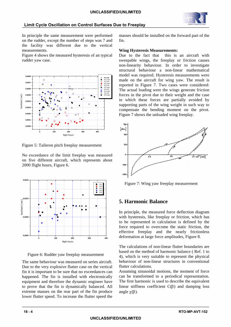
Figure 5: Taileron pitch freeplay measurement No exceedance of the limit freeplay was measured on five different aircraft, which represents about 2000 flight hours, Figure 6.
0 100 200 300 4000,0000
0,0005
0,0010
0,0015
flight hours
back
lash
[ ra
d ]
AC1 AC2 AC3 AC4 AC5
Figure 6: Rudder yaw freeplay measurement
The same behaviour was measured on series aircraft. Due to the very explosive flutter case on the vertical fin it is important to be sure that no exceedances can happened. The fin is installed with electronically equipment and therefore the dynamic engineer have to prove that the fin is dynamically balanced. All extreme masses on the rear part of the fin produce lower flutter speed. To increase the flutter speed the
masses should be installed on the forward part of the fin. Wing Hysteresis Measurements: Due to the fact that this is an aircraft with sweepable wings, the freeplay or friction causes non-linearity behaviour. In order to investigate structural behaviour a non-linear mathematical model was required. Hysteresis measurements were made on the aircraft for wing yaw. The result is reported in Figure 7. Two cases were considered: The actual loading were the wings generate friction forces in the pivot due to their weight and the case in which these forces are partially avoided by supporting parts of the wing weight in such way to compensate the bending moment on the pivot. Figure 7 shows the unloaded wing freeplay.
Figure 7: Wing yaw freeplay measurement
5. Harmonic Balance In principle, the measured force deflection diagram with hysteresis, like freeplay or friction, which has to be represented in calculation is defined by the force required to overcome the static friction, the effective freeplay and the nearly frictionless deformation at large force amplitudes, Figure 8. The calculations of non-linear flutter boundaries are based on the method of harmonic balance ( Ref. 1 to 4), which is very suitable to represent the physical behaviour of non-linear structures in conventional flutter calculations. Assuming sinusoidal motions, the moment of force can be transformed to a periodical representation. The first harmonic is used to describe the equivalent linear stiffness coefficient C(β) and damping loss angle χ(β).
Limit Cycle Oscillation on Control Surfaces Due to Freeplay
18 - 4 RTO-MP-AVT-152
UNCLASSIFIED/UNLIMITED
UNCLASSIFIED/UNLIMITED

( ) ( )C f dβπβ
β ϕ βω ϕ ϕ ϕϕ
π
= ⋅ − ⋅=∫
1
0
2
cos , sin cos
( ) ( ) ( )χ βπβ β
β ϕ βω ϕ ϕ ϕϕ
π
= ⋅ − ⋅=∫
1
0
2
Cf dcos , sin sin
which can be performed with a fast Fourier transformation.
Figure 8: Measured Hysteresis of wing pivot yaw deflection
Figure 9 depicts in principle the linear stiffness approximation of hysteresis type deflection curves which have to be performed for different amplitudes. The extreme points of this stiffness and damping slopes have been used for selected flutter calculations in order to show the influence of the wing pivot freeplay. It was known from analysis that the flutter speed of the clean wing is about twice of the design speed.
Figure 9: Linearized stiffness and damping of wing pivot versus wing yaw deflection
6. Modelling Complete aircraft structural model representation was formed by a combination of individual surface fixed root branch modes, junction or direct load modes and rigid body modes. The mathematical model is divided into the following main components: • fuselage, including nose and main undercarriage • taileron including attachment and actuator • Fin and rudder, including attachment and
actuator • wing including actuator and carry through box
flexibility The frequencies of the component branch modes have been adapted to match the total A/C frequencies (table 1) and coupling mechanism as resulted from total A/C ground resonance test. Taileron The taileron, for instance is represented by 158 finite element grid points, describing vertical deflections. The taileron is restrained at the spigot and actuator attachment of the lever arm. The lever arm is an integral part of the tailplane root rib and it is appropriate to include the flexibility of this element in the tailplane flexibility matrix used for the determination of fixed root normal modes. The stiffness matrix for the rigid tailplane component modes representing the tailplane to fuselage attachments is approximately if the vertical inclination of the jack is considered.
Limit Cycle Oscillation on Control Surfaces Due to Freeplay
RTO-MP-AVT-152 18 - 5
UNCLASSIFIED/UNLIMITED
UNCLASSIFIED/UNLIMITED
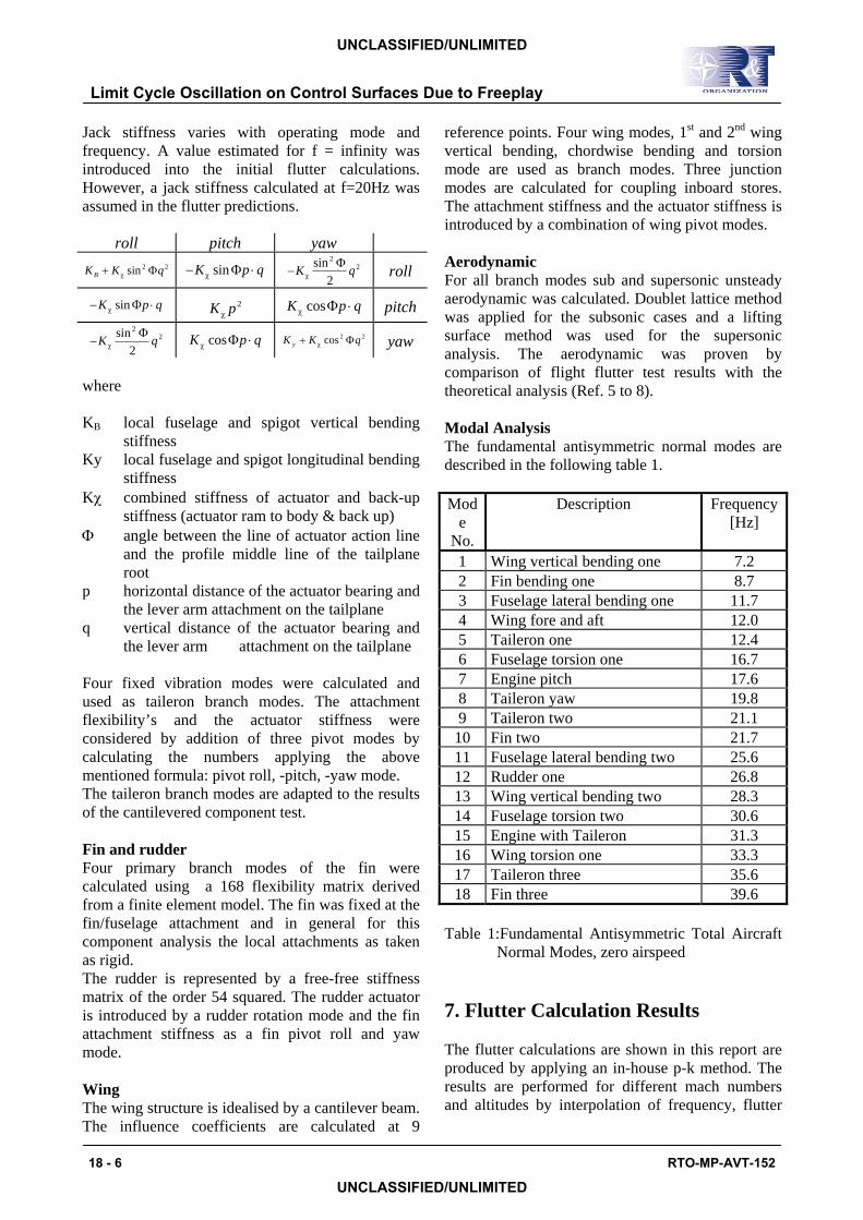
Jack stiffness varies with operating mode and frequency. A value estimated for f = infinity was introduced into the initial flutter calculations. However, a jack stiffness calculated at f=20Hz was assumed in the flutter predictions.
roll pitch yaw K K qB + χ sin 2 2Φ − ⋅K p qχ sinΦ −K qχ
sin 22
2Φ roll
− ⋅K p qχ sinΦ K pχ2 K p qχ cosΦ ⋅ pitch
−K qχsin 2
2
2Φ K p qχ cosΦ ⋅ K K qy + χ cos2 2Φ yaw
where KB local fuselage and spigot vertical bending
stiffness Ky local fuselage and spigot longitudinal bending
stiffness Kχ combined stiffness of actuator and back-up
stiffness (actuator ram to body & back up) Φ angle between the line of actuator action line
and the profile middle line of the tailplane root
p horizontal distance of the actuator bearing and the lever arm attachment on the tailplane
q vertical distance of the actuator bearing and the lever arm attachment on the tailplane
Four fixed vibration modes were calculated and used as taileron branch modes. The attachment flexibility’s and the actuator stiffness were considered by addition of three pivot modes by calculating the numbers applying the above mentioned formula: pivot roll, -pitch, -yaw mode. The taileron branch modes are adapted to the results of the cantilevered component test. Fin and rudder Four primary branch modes of the fin were calculated using a 168 flexibility matrix derived from a finite element model. The fin was fixed at the fin/fuselage attachment and in general for this component analysis the local attachments as taken as rigid. The rudder is represented by a free-free stiffness matrix of the order 54 squared. The rudder actuator is introduced by a rudder rotation mode and the fin attachment stiffness as a fin pivot roll and yaw mode. Wing The wing structure is idealised by a cantilever beam. The influence coefficients are calculated at 9
reference points. Four wing modes, 1st and 2nd wing vertical bending, chordwise bending and torsion mode are used as branch modes. Three junction modes are calculated for coupling inboard stores. The attachment stiffness and the actuator stiffness is introduced by a combination of wing pivot modes. Aerodynamic For all branch modes sub and supersonic unsteady aerodynamic was calculated. Doublet lattice method was applied for the subsonic cases and a lifting surface method was used for the supersonic analysis. The aerodynamic was proven by comparison of flight flutter test results with the theoretical analysis (Ref. 5 to 8). Modal Analysis The fundamental antisymmetric normal modes are described in the following table 1. Mod
e No.
Description Frequency [Hz]
1 Wing vertical bending one 7.2 2 Fin bending one 8.7 3 Fuselage lateral bending one 11.7 4 Wing fore and aft 12.0 5 Taileron one 12.4 6 Fuselage torsion one 16.7 7 Engine pitch 17.6 8 Taileron yaw 19.8 9 Taileron two 21.1
10 Fin two 21.7 11 Fuselage lateral bending two 25.6 12 Rudder one 26.8 13 Wing vertical bending two 28.3 14 Fuselage torsion two 30.6 15 Engine with Taileron 31.3 16 Wing torsion one 33.3 17 Taileron three 35.6 18 Fin three 39.6
Table 1:Fundamental Antisymmetric Total Aircraft Normal Modes, zero airspeed 7. Flutter Calculation Results The flutter calculations are shown in this report are produced by applying an in-house p-k method. The results are performed for different mach numbers and altitudes by interpolation of frequency, flutter
Limit Cycle Oscillation on Control Surfaces Due to Freeplay
18 - 6 RTO-MP-AVT-152
UNCLASSIFIED/UNLIMITED
UNCLASSIFIED/UNLIMITED

speed and unsteady aerodynamic. No interpolation was done between the investigated Mach numbers. Symmetric flutter calculations are not shown here because there is no potential symmetric flutter on the clean aircraft. Critical modes in view of flutter are the taileron one, two and yaw, fin one and two, wing bending and torsion one. These modes are well represented in the mathematical model. Apex mass-balance was required to satisfy the flutter requirements. Linear mathematical model gave very accurate predictions of the flutter characteristics and gave sufficient confidence for flutter testing to be carried out very close to the critical flutter speed. In general three potential flutter cases are involved . • the flutter mode I at approximately 15 Hz which
is dominated by the fuselage torsion mode with contribution of the fundamental taileron and fin modes (empanage flutter)
• the flutter mode II at approximately 19 Hz which represents mainly the second taileron mode.
• and the fin flutter mode III at approximately 17 Hz for subsonic speeds and about 25 Hz for supersonic speeds which is effected very little by taileron changes and which has higher flutter speeds.
Figure 10: Damping versus flutterspeed Kjack variation, Mach=0.9
Figure 11: Damping versus flutter speed, Kjack variation Mach=1.8 With massbalance and all systems working in normal mode the clean A/C is free of flutter over the complete envelope. Main focus was on the supersonic analysis because it turned out that the worst case on taileron flutter of the claean aircraft is between Mach 1.4 and 2.2. Taileron analysis Due to the interaction of the taileron actuator matrix the investigation was performed in two different steps. • Variation of the actuator stiffness (kjack-vari) • Variation of the vertical back up stiffness (kb
vari) Basically, the taileron flutter is influenced by the taileron yaw mode in combination with the taileron two mode. The taileron yaw mode is directly influenced by the actual stiffness of the actuator acting. Kjack variation Results of flutter calculations using linear stiffness of the actuator depicted for the two taileron fluttermodes in Figure 10 for subsonic and in Figure 11 for supersonic. Due to the serial connection of the taileron structure with the actuator and the fuselage, the reduction of the actual available stiffness at the lever arm is fundamental.
Limit Cycle Oscillation on Control Surfaces Due to Freeplay
RTO-MP-AVT-152 18 - 7
UNCLASSIFIED/UNLIMITED
UNCLASSIFIED/UNLIMITED
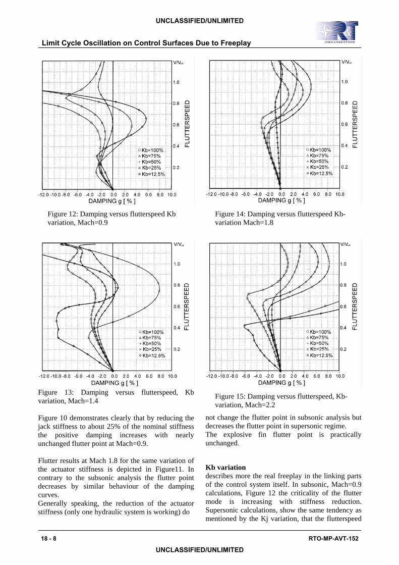
Figure 12: Damping versus flutterspeed Kb variation, Mach=0.9
Figure 13: Damping versus flutterspeed, Kb variation, Mach=1.4 Figure 10 demonstrates clearly that by reducing the jack stiffness to about 25% of the nominal stiffness the positive damping increases with nearly unchanged flutter point at Mach=0.9. Flutter results at Mach 1.8 for the same variation of the actuator stiffness is depicted in Figure11. In contrary to the subsonic analysis the flutter point decreases by similar behaviour of the damping curves. Generally speaking, the reduction of the actuator stiffness (only one hydraulic system is working) do
Figure 14: Damping versus flutterspeed Kb-variation Mach=1.8
Figure 15: Damping versus flutterspeed, Kb-variation, Mach=2.2
not change the flutter point in subsonic analysis but decreases the flutter point in supersonic regime. The explosive fin flutter point is practically unchanged. Kb variation describes more the real freeplay in the linking parts of the control system itself. In subsonic, Mach=0.9 calculations, Figure 12 the criticality of the flutter mode is increasing with stiffness reduction. Supersonic calculations, show the same tendency as mentioned by the Kj variation, that the flutterspeed
Limit Cycle Oscillation on Control Surfaces Due to Freeplay
18 - 8 RTO-MP-AVT-152
UNCLASSIFIED/UNLIMITED
UNCLASSIFIED/UNLIMITED
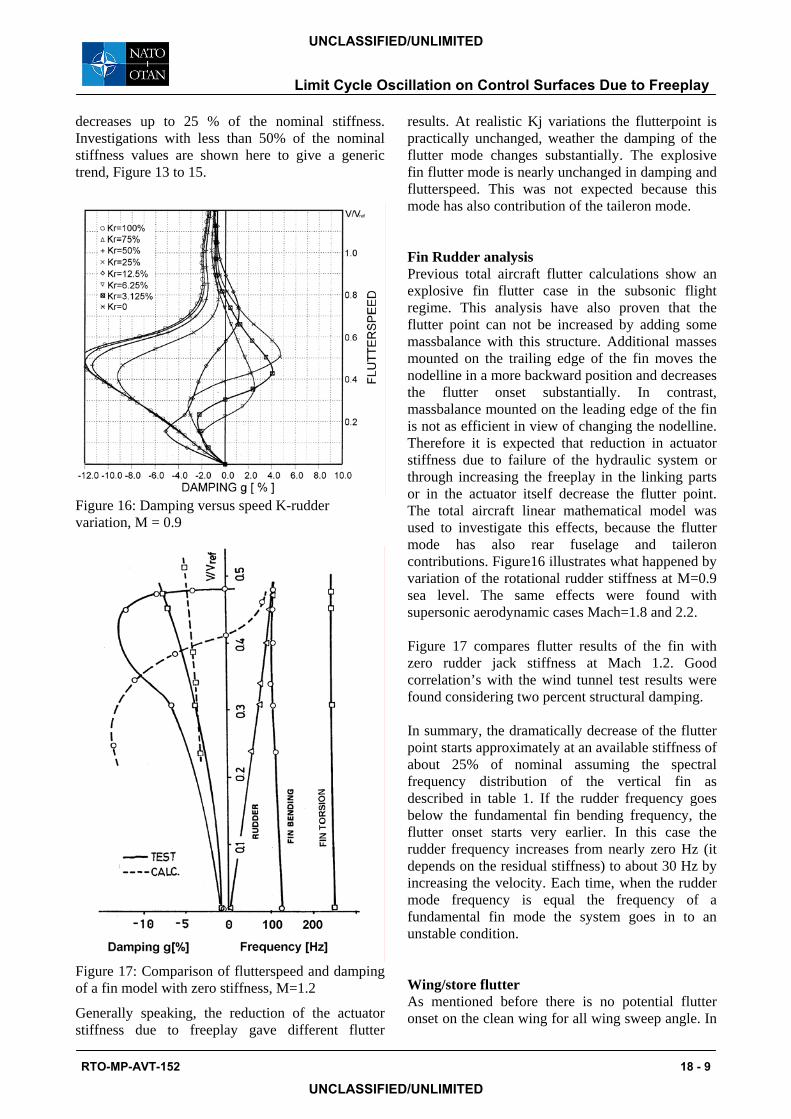
decreases up to 25 % of the nominal stiffness. Investigations with less than 50% of the nominal stiffness values are shown here to give a generic trend, Figure 13 to 15.
Figure 16: Damping versus speed K-rudder variation, M = 0.9
Figure 17: Comparison of flutterspeed and damping of a fin model with zero stiffness, M=1.2
Generally speaking, the reduction of the actuator stiffness due to freeplay gave different flutter
results. At realistic Kj variations the flutterpoint is practically unchanged, weather the damping of the flutter mode changes substantially. The explosive fin flutter mode is nearly unchanged in damping and flutterspeed. This was not expected because this mode has also contribution of the taileron mode. Fin Rudder analysis Previous total aircraft flutter calculations show an explosive fin flutter case in the subsonic flight regime. This analysis have also proven that the flutter point can not be increased by adding some massbalance with this structure. Additional masses mounted on the trailing edge of the fin moves the nodelline in a more backward position and decreases the flutter onset substantially. In contrast, massbalance mounted on the leading edge of the fin is not as efficient in view of changing the nodelline. Therefore it is expected that reduction in actuator stiffness due to failure of the hydraulic system or through increasing the freeplay in the linking parts or in the actuator itself decrease the flutter point. The total aircraft linear mathematical model was used to investigate this effects, because the flutter mode has also rear fuselage and taileron contributions. Figure16 illustrates what happened by variation of the rotational rudder stiffness at M=0.9 sea level. The same effects were found with supersonic aerodynamic cases Mach=1.8 and 2.2. Figure 17 compares flutter results of the fin with zero rudder jack stiffness at Mach 1.2. Good correlation’s with the wind tunnel test results were found considering two percent structural damping. In summary, the dramatically decrease of the flutter point starts approximately at an available stiffness of about 25% of nominal assuming the spectral frequency distribution of the vertical fin as described in table 1. If the rudder frequency goes below the fundamental fin bending frequency, the flutter onset starts very earlier. In this case the rudder frequency increases from nearly zero Hz (it depends on the residual stiffness) to about 30 Hz by increasing the velocity. Each time, when the rudder mode frequency is equal the frequency of a fundamental fin mode the system goes in to an unstable condition. Wing/store flutter As mentioned before there is no potential flutter onset on the clean wing for all wing sweep angle. In
Limit Cycle Oscillation on Control Surfaces Due to Freeplay
RTO-MP-AVT-152 18 - 9
UNCLASSIFIED/UNLIMITED
UNCLASSIFIED/UNLIMITED

order to show the influence of freeplay in the wing pivot flutter calculations have been performed with mounted heavy inboard store. For the nominal linear wing pivot yaw stiffness, derived during measurements at large amplitudes the wing yaw frequency is well separated from the store pitch mode. (The flutter mechanism is defined by the store pitch mode at about 4.1 Hz and the wing bending mode at about 3.4 Hz). Measurements of the hysteresis curve were used for the harmonic balance approach, Figure 8. The equivalent linear stiffness and damping loss angle as derived from harmonic approximation are plotted in Figure 9 versus wing yaw amplitude. Starting with large stiffness and zero damping at small deflections the stiffness reaches the lowest and the damping the largest value when the deflection achieves the hysteresis amplitude at β=β0. At amplitudes >β0 the damping went to zero and the stiffness tends to the linear value. For amplitudes below the critical slip-stick the force deflection curve is not defined due to difficulties arising from stiffness measurements at small amplitudes. The results of flutter speeds were found for very small and very large amplitudes where the stiffness reaches about the linear value. In both cases apparently no damping is introduced by the wing pivot yaw mode, Figure 18.
Figure 18: Flutter speed versus wing pivot yaw stiffness
For amplitudes inside the hysteresis curve, high flutter speeds have been calculated which could be explained by the influence of the hysteresis damping. 8. CONCLUSION
The study discussed in this report is based on many simplifications, and therefore it would be imprudent to expect a one for one numerical correlation of the results with actual actuator, store/aircraft combination. The trend established, however, are considered are valid. Based on this trends, the following conclusions are drawn: • The harmonic balance method could be
considered as a suitable tool for project LCO and flutter analysis with simple non-linearity’s.
• Non-linearity’s in the actuator due to backlash rise a LCO or flutter speed considerably lower than those of the linear flutter model.
However, the analysis predicts the LCO and flutter phenomena when the actuator stiffness is reduced by about 50 percent. This reduction is somewhat more than generally used in past, but trends agree with available wind tunnel test results. For further investigations also more accurate aerodynamic should be applied. 9. References [1]Bogoljubow N. N., Mitropolski J. A. Asymptotische Methoden in der Theorie der linearen Schwingungen. Akademie Verlag Berlin (1965) [2] Breitbach E. Effects of Structural Nonlinearities on Aircraft Vibration and Flutter AGARD-R-665 (1977) [3] Hönlinger H., Luber W., Mussmann D. Dynamisches Verhalten elastischer Strukturen bei Nichtlinearitäten MBB-Report 1979 [4] De Ferrari G., Chesta L., Sensburg O., Lotze A. Effects of Nonlinearities on Wing Store Flutter AGARD-R-687; 50th AGARD SMP Conference April 1980 Athens, Greece. [5] Luber W., Schmid H. Flutter investigation in the transonic flow regime for a fighter type aircraft AGARD-R-703; 55th AGARD SMP conference, Toronto, Canada, Sept. 1982
Limit Cycle Oscillation on Control Surfaces Due to Freeplay
18 - 10 RTO-MP-AVT-152
UNCLASSIFIED/UNLIMITED
UNCLASSIFIED/UNLIMITED

[6] French M., Noll T., Cooley D., Moore R., Zapata F. Flutter Investigation Involving a Free Floating Aileron. AIAA-87-0909 [7] Becker J., Luber W. Unsteady Aerodynamic Forces at High Incidence and their Application in Structural- and Flight Control Design International Forum on Aeroelasticity and Structural Dynamics; Manchester, UK, June 1995 [8] Heller G., Kreiselmeier E. Eulerluftkräfte für Klappenschwingungen TUM-FLM-96/05; Lehrstuhl für Fluidmechanik, Technische Universität München
Limit Cycle Oscillation on Control Surfaces Due to Freeplay
RTO-MP-AVT-152 18 - 11
UNCLASSIFIED/UNLIMITED
UNCLASSIFIED/UNLIMITED

Limit Cycle Oscillation on Control Surfaces Due to Freeplay
18 - 12 RTO-MP-AVT-152
UNCLASSIFIED/UNLIMITED
UNCLASSIFIED/UNLIMITED