Embed Size (px)
Citation preview

LightweightOffshoreSubstationDesigns
FinalSummaryReport
January2016
ReportintoLightweightOffshoreSubstationDesigns
2
DISCLAIMER
Whilsttheinformationcontainedinthisreporthasbeenpreparedandcollatedingoodfaith,theOffshoreWindProgrammeBoard(OWPB)andtheauthorsmakenorepresentationorwarranty(expressorimplied)astotheaccuracyorcompletenessoftheinformationcontainedinthisreport(includinganyenclosuresandattachments)norshalltheybeliableforanylossordamage,whetherdirectorconsequential,arisingfromrelianceonthisreportbyanyperson.Inparticular,butwithoutlimitation,theOWPBandtheauthorsacceptnoresponsibilityforaccuracyandcompletenessforanycommentson,oropinionsregardingthefunctionalandtechnicalcapabilitiesofanyequipment,softwareorotherproductsmentionedinthereport.TheOWPBandtheauthorsarenotresponsibleinanywayinconnectionwitherroneousinformationordatacontainedorreferredtointhisdocument.Itisuptothosewhousetheinformationinthisreporttosatisfythemselvesastoitsaccuracy.Thisreportanditscontentsdonotconstituteprofessionaladvice.Specificadviceshouldbesoughtaboutyourspecificcircumstances.Thereporthasbeenproducedbytheauthorsbasedoninformationprovidedbysuppliers,developersandotherindustryparticipantsandhasnotbeensubjecttoindependentverification.TheOWPBandtheauthorsacceptnoresponsibilityforaccuracyandcompletenessofanycommentson,oropinionsregardingthefunctionalandtechnicalcapabilitiesof,anyproductsorservicesmentioned.Thereportisnotintendedtobeaninstructional,torequireanyaffectedpartytobehaveinacertainwayortoremovetherightofanysuchpartytotakeitsowncommercialdecisionsontheissuesdiscussedherein.Tothefullestextentpossible,theOWPBandtheauthorsdisclaimanyliabilityarisingoutoftheuseofthereport,includinganyactionordecisiontakenasaresultofsuchuse.

ReportintoLightweightOffshoreSubstationDesigns
3
ABBREVIATIONSUSED
Initials Definition
CT CurrentTransformerDC DirectCurrentDFF DesignFatigueFactorDP2 DynamicPositioning(withClass2redundancy)DTS DistributedTemperatureSensorEPCI Engineer,Procure,Construct,InstallEWEA EuropeanWindEnergyAssociationFEED FrontEndEngineeringDesignFID FinalInvestmentDecisionGIS GasInsulatedSwitchgearHAZID HAZardIDentificationstudykV KiloVoltkVA KiloVolt-AmperekW KiloWattMV MediumVoltage(i.e.33kVor66kV)MVA MegaVoltAmpereMVAr MegaVoltAmpereReactiveMW MegawattOFTO OffshoreTransmissionownerO&M Operations&MaintenanceONAN OilNaturalAirNatural(transformercooling)OTM OffshoreTransformerModuleOWPB OffshoreWindProgrammeBoardRAM Reliability,AvailabilityandMaintainabilitySCADA SupervisoryControlandDataAcquisitionSQSS SecurityandQualityofSupplyStandardsTRS TenderRevenueStreamVT VoltageTransformerWTG WindTurbineGenerator

ReportintoLightweightOffshoreSubstationDesigns
4
TableofContents
Disclaimer.....................................................................................................................................2
AbbreviationsUsed.......................................................................................................................3
1 SUMMARY&CONCLUSIONS............................................................................................5
2 INTRODUCTIONANDBACKGROUND...............................................................................9
3 LIGHTWEIGHTOFFSHORESUBSTATIONS......................................................................113.1 Definition.................................................................................................................................113.2 Comparisonwith“Traditional”OffshoreSubstations.............................................................123.3 ImplicationsofaLightweightDesign.......................................................................................133.4 LightweightSubstationImplementations...............................................................................15
4 THESIEMENSOFFSHORETRANSFORMERMODULE.....................................................194.1 StandardFeatures...................................................................................................................204.2 OptionalFeatures....................................................................................................................21
5 ISSUESANDMITIGATIONS-SAFETY..............................................................................225.1 FireProtection.........................................................................................................................225.2 BladeClearance.......................................................................................................................225.3 HazardIdentification(HAZID)studies.....................................................................................23
6 ISSUESANDMITIGATIONS–RELIABILITY,AVAILABILITY&MAINTAINABILITY.............256.1 ImpactofTransformerFaults..................................................................................................256.2 ExperiencewithSyntheticEsters............................................................................................266.3 OffshoreLogistics....................................................................................................................266.4 SpaceforMaintenanceandRepairs........................................................................................276.5 OFTO/GeneratorSegregation................................................................................................276.6 Corrosion.................................................................................................................................286.7 AuxiliaryPower.......................................................................................................................286.8 CablePull-in.............................................................................................................................29
7 OTMSTRUCTURALDESIGN............................................................................................307.1 StandaloneOTMonJacketSubstationSubstructure..............................................................307.2 IntegratedOTMonJacketSubstructure(sharedwithWindTurbine)....................................307.3 DesignFatigueFactor..............................................................................................................317.4 IntegratedOTMonMonopileSubstructure(sharedwithWindTurbine)...............................327.5 SubstationTopsidesStructure................................................................................................337.6 VerifyingtheFeasibilityofanOTMwithShuntReactors........................................................347.7 ContractualInterfaceConsiderations.....................................................................................35
8 COSTREDUCTION...........................................................................................................378.1 ImpactofWindFarmSize.......................................................................................................378.2 IndependentCalculationofCostSavingsforaStandaloneOTM............................................388.3 IndependentCalculationofAdditionalCostSavingsforanIntegratedOTM..........................408.4 MVCablesOptimisation..........................................................................................................428.5 ConclusionsinRelationtoCostReduction..............................................................................428.6 CostSavingin£/MWhrTerms.................................................................................................43

ReportintoLightweightOffshoreSubstationDesigns
5
1 SUMMARY&CONCLUSIONS
Thisreportdescribestheconceptofa“lightweight”offshoresubstation,andinparticular itdescribesoneimplementationoftheconcept:theOffshoreTransformerModule(OTM)whichhasbeendevelopedbySiemens.TheOTMconceptexistsindifferentversions:
i) itcanbe“standalone”(theOTMoccupiesitsownsubstructure)or“integrated”(theOTMsharesasubstructurewithawindturbine);
ii) itcanincorporateashuntreactorwherenecessary(e.g.duetoverylongexportcables);
iii) thesubstructurecanbeajacket,amonopile,or–inprinciple–anadaptedform
ofanysubstructuresuitablefora7-8MWwindturbine;
iv) various “optional extras” such as lifting frames, louvered walls around thetransformer,or largerplatformcranescanbe incorporatedwithoutaffectingthemaindesignoftheOTM.
The“basedesigncases”thathavereceivedthebulkofthedesignworkarethestandaloneandintegrated versions of theOTM,without reactors or optional extras, on four-legged jacketsubstructures. Siemens has undertaken considerable development work on these basedesigns:theynotethattheirdevelopmentworkhas“spanned130technicaldeliverablesand12 months of design work using real project site conditions”. Notice to proceed withconstructionofthefirstOTMsisexpectedwithinlessthan12months.Siemens’sdesire is toputextraeffort intooptimisingthesebasecasedesigns,andthentoadaptthesebasedesignstoyieldthedesignsforfutureprojectsratherthandesigningthenewprojectsfromacleansheet;theyrefertothisasa“adoptingaproductmentality”.Theauthorsofthisreportagreethatthisapproachshouldallowreductionsindesigntime,costandriskonfutureprojects.Thereportconcludesthat:
i) TheOTMconceptcanbeexpectedtoreducecostsby£1.7/MWhr(in2015prices).ThisfigureisbasedontheintegratedOTMdesign.Itwouldbeaboutathirdlessforthestandalonedesign,whileahighervalueislikelyiftheOTMweretobeappliedalongsideanarraydesignthathadbeenoptimisedforOTMs.
ii) TheOTMappearswellengineered,andalthoughitincludesseveralmeasuresnew
totheUKwindindustryinordertoreducecostandweight,theseappeartohavebeen applied with suitable consideration given to the need to ensure safety,reliability, availability and maintainability. Our conclusions on these issues aresummarisedintable1below.

ReportintoLightweightOffshoreSubstationDesigns
6
iii) Thestandalonebasedesignisreadyforimmediatecommitmentbydevelopers(i.e.developersselectingthisconceptcanbeconfidentthatitisfeasibleandwillprovidesignificantcostsavings).
iv) The integrated base design is also ready for immediate commitment, although
developerswillfirstneedtoconfirmthattheyarecomfortablewiththeadditionalcontractualinterfaces.
v) ThelevelofreadinessforvariousOTMversionsissetoutinTable2below.
vi) Siemensisnottheonlycompanycurrentlyinvestigatingthepotentialoflightweight
single-transformer substations, and the concept could also be applied by othermanufacturersorbydeveloperswhochosetoengineertheiroffshoresubstationsin-house.
vii) ORECatapulthasrecentlyundertakenastudyoftheaccelerationsexperiencedat
the tower-base level of a wind turbine and their acceptability to high-voltageequipment.Whilethisparticularstudyisratherbasicandonlycoversonescenario,itmayprovideinsightintothescopeofamorecomprehensivestudythatwouldbeabletoalleviatecurrentconcernsthatsubstationequipmentcouldsufferlong-termwearduetotheincreasedaccelerationsimposedbysharingasubstructurewithawindturbine.
viii) FurtherworkbyOWPBisrecommendedtoinvestigatethepotentialforincreased
costsavingsbyoptimisingthearraycablingforthecharacteristicsof lightweightsubstations. The authors also encourage Siemens to undertake further workrefiningversionsoftheOTMthatincludeashuntreactorandthatusemonopilesubstructures.
Table1:SummaryofConclusionsinrelationtoSafety,Reliability,AvailabilityandMaintainabilityIssue
Mitigation/Authors’Commentary
Fireprotection DNVhasagreedcompliancewithDNV-OS-J201(subjecttofinalstudyatdetaileddesignstage).FurthermoretheOTMhasbetterfireprotectionthanseveralUKoffshoresubstationsalreadyinservicewithOFTOs.
HAZIDstudyforstandaloneOTM
HAZIDconcludedthatrisksaresimilarorlessthanonconventionalsubstations
HAZIDstudyforintegratedOTM
HAZIDidentifiedpotentialrisksfromobjectsdroppedfromturbineontoOTM,fromicedroppedfromturbineontoOTM,andfromafireontheOTMwhenpersonnelareintheturbine.
MitigatingmeasurewereidentifiedforalloftheserisksandSiemensandthedeveloperwereconfidentthatthesecouldhavebeensuccessfullyapplied.
FaultonanOTM’ssingletransformer
ThesizeofUKwindfarmsissuchthatallwouldbeexpectedtohaveatleasttwoOTMs.ThisreportassumesthroughoutthatthesemultipleOTMswouldbeconnectedbycablessothat,shouldatransformerfail,powercanbererouted

ReportintoLightweightOffshoreSubstationDesigns
7
throughthetransformerinanotherOTM.
SufficientOTM-to-OTMcablestogivealevelofresilienceagainsttransformerfaultsfullyequivalenttoaconventionaltwo-transformeroffshoresubstationareincludedinthe£1.7/MWhrOTMbenefitfigure(seesection8).
Syntheticester:limitedtrackrecordat≥220kV
Followingtestsonasamplesimulatinga400/132kVtransformer,NationalGridnowacceptssyntheticestercooledtransformersat400kV.ThefirstsuchtransformershavebeenmanufacturedbySiemensandaretoenterserviceinlate2015.Thisriskthereforeappearstobeacceptable.
Nohelideck Aheli-hoistareaisprovided.HelidecksareunusualonUKoffshoresubstations.StudiesbyTenneTfortheirforthcomingDutchoffshoresubstationsindicatedthattheadditionalcostofahelideckcannotbejustified.
Siemens’sdecisionnottoprovideahelideckis,therefore,reasonable.
Limitedplatformcranecapacity
Siemenshasyettodeterminethespecificationforthebase-designOTM’splatformcrane.Itisthereforepossiblethatthecranewillhaveinsufficientcapacitytoliftsomeoftheheavierspareparts(e.g.auxiliarytransformer,220kVVT)whichcanbeliftedonmostconventionalsubstations.
Siemenshaveconfirmedthatiftheplatformcranechosenforthebasedesignisjudgedinadequatebycustomersthentheycanprovideanupratedcraneasanoption.
Spaceformaintenance&repairs
SiemenshasconfirmedthattheclearancearoundallelectricalequipmentontheOTMmeetsalloftheirown“manufacturer’srecommendations”foronshoreinstallations.
OFTO/Generatorsegregation
OFTO-ownedandgenerator-ownedequipmentisnotinseparaterooms,butisinseparatelylockablecabinets.Thisisconsideredacceptable.
ThebasedesignprovidesasinglesubstationcontrolsystemforgeneratorandOFTOownedassets.SiemenshaveconfirmedthatifthisnotacceptabletocustomersthenthereissufficientpanelspacetoallowseparatesubstationcontrolsystemsforthegeneratorandOFTOtobefitted.
Corrosion AllOTMtransformercoolerscanbereplacedwithoutde-energisingthetransformerandwithoutneedingexternalcranesoranyboatlargerthanacrewtransfervessel.Thisisbetterthanmostconventionalsubstations.
Nodieselforemergencypower
ThisreportassumesthroughoutthatUKwindfarmswillhavemultipleOTMsandOTM-to-OTMcables.TheselinkstotheotherOTM(s)inthewindfarmmeanthatemergencypoweronanOTMshouldbemorereliablethanonaconventionalsubstationwithasingleexportcableandadiesel.Siemens’sapproachisthereforeconsideredacceptable.
CablePull-in Siemenshaveundertakendetailedplanningandstoryboarding.
DesignFatigueFactoronintegratedOTM
OntheintegratedOTMtheDFFisreducedfromthevalueof10specifiedinDNV-OS-J201toavalueof6.SiemenshasagreedthiswithDNV,anditisexpectedthatDNVwouldcertifyanintegratedOTMonthisbasis.

ReportintoLightweightOffshoreSubstationDesigns
8
Table2:ReadinessofOTMConceptVariant
Readiness
StandaloneOTMonajacketsubstructure
(OneoftheBaseDesignCases)
Readyforimmediatecommitmentbydevelopers.
IntegratedOTMwithawindturbinesharingjacketsubstructure
(OneoftheBaseDesignCases)
Readyforimmediatecommitmentbydevelopers.
Notethatforsomedevelopersthisoptionmayrequiretheacceptanceofadditionalcontractualinterfaces.
StandaloneOTMontripodorgravitybasesubstructure
Readyforimmediatecommitmentbydevelopers.
StandaloneOTMonmonopile Readyforcommitmentbydeveloperssubjectto:• checkingthatthemovementamplitudesandfrequencies
thatwouldbeexperiencedwhenusingamonopileadaptedfromoneintendedforwindturbineserviceareacceptableforhighvoltageequipment,and
• checkinghowtherequirednumberofcableJ-tubeswillbeaccommodated.
OTMwithaShuntReactor Readyforimmediatecommitmentbydevelopers.(AlthoughSiemenshavenotcompleteddesignworkonanOTMwithashuntreactor,theyareconfidentofthefeasibilityofthisversion.Aproof-of-conceptcheckbytheauthors–seesection7.6–tendstoconfirmSiemens’sposition).
OTMsharingamonopilesubstructurewithawindturbine(“integrated”)
InadditiontothestudiesdescribedaboveforastandaloneOTMonamonopile,theauthorsrecommendanadditionalstudytoinvestigatewhetherlong-termcyclicaccelerationlevelscouldbemateriallyincreasedbythepresenceoftheturbine,and–ifso–whetherthiswouldbeacceptableforhighvoltageequipment.
StandaloneOTMequivalentbynon-Siemensvendor.
ThereappearstobenoreasonwhyothervendorscannotprovidelightweightsubstationswiththesamespecificationsastheOTM.HowevertheFEEDprocessalreadycompletedbySiemensfortheirbasedesignswouldneedtoberepeatedbyothervendors.
IntegratedOTMequivalentbynon-Siemensvendor.
SiemenshasappliedforapatentcoveringaspectsoftheirintegratedOTMbasedesign.Itisbeyondthescopeofthisreporttocommentonthelikelihoodofthispatentbeinggrantedortheconsequencesifitis.Theauthorshavenotbeenabletolocatethetextofthepatentapplication.
ReportintoLightweightOffshoreSubstationDesigns
9
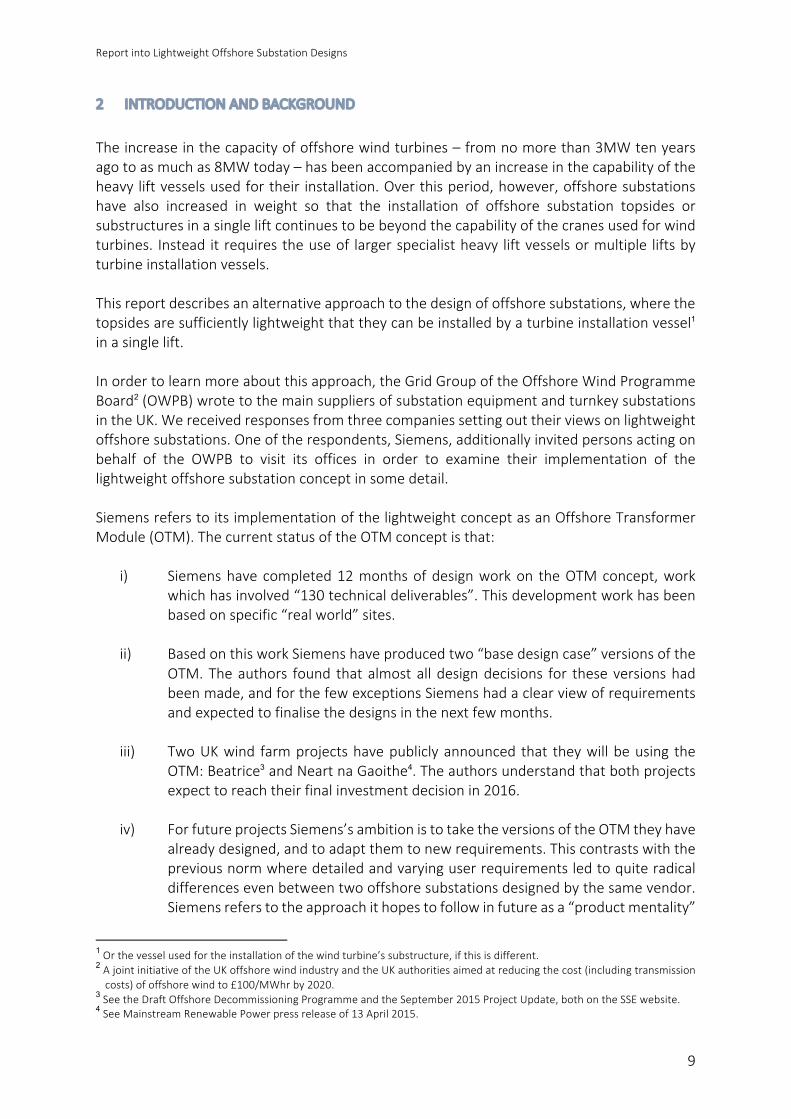
2 INTRODUCTIONANDBACKGROUND
Theincreaseinthecapacityofoffshorewindturbines–fromnomorethan3MWtenyearsagotoasmuchas8MWtoday–hasbeenaccompaniedbyanincreaseinthecapabilityoftheheavyliftvesselsusedfortheir installation.Overthisperiod,however,offshoresubstationshave also increased in weight so that the installation of offshore substation topsides orsubstructuresinasingleliftcontinuestobebeyondthecapabilityofthecranesusedforwindturbines. Instead itrequirestheuseof largerspecialistheavy liftvesselsormultiple liftsbyturbineinstallationvessels.Thisreportdescribesanalternativeapproachtothedesignofoffshoresubstations,wherethetopsidesaresufficientlylightweightthattheycanbeinstalledbyaturbineinstallationvessel1inasinglelift.Inordertolearnmoreaboutthisapproach,theGridGroupoftheOffshoreWindProgrammeBoard2(OWPB)wrotetothemainsuppliersofsubstationequipmentandturnkeysubstationsintheUK.Wereceivedresponsesfromthreecompaniessettingouttheirviewsonlightweightoffshoresubstations.Oneoftherespondents,Siemens,additionallyinvitedpersonsactingonbehalf of the OWPB to visit its offices in order to examine their implementation of thelightweightoffshoresubstationconceptinsomedetail.SiemensreferstoitsimplementationofthelightweightconceptasanOffshoreTransformerModule(OTM).ThecurrentstatusoftheOTMconceptisthat:
i) Siemenshave completed12monthsofdesignworkon theOTMconcept,workwhichhasinvolved“130technicaldeliverables”.Thisdevelopmentworkhasbeenbasedonspecific“realworld”sites.
ii) BasedonthisworkSiemenshaveproducedtwo“basedesigncase”versionsoftheOTM.Theauthors found thatalmostall designdecisions for theseversionshadbeenmade,andforthefewexceptionsSiemenshadaclearviewofrequirementsandexpectedtofinalisethedesignsinthenextfewmonths.
iii) TwoUKwind farmprojectshavepubliclyannounced that theywillbeusing the
OTM:Beatrice3andNeartnaGaoithe4.Theauthorsunderstandthatbothprojectsexpecttoreachtheirfinalinvestmentdecisionin2016.
iv) ForfutureprojectsSiemens’sambitionistotaketheversionsoftheOTMtheyhave
alreadydesigned,andtoadaptthemtonewrequirements.Thiscontrastswiththepreviousnormwheredetailedandvaryinguserrequirementsledtoquiteradicaldifferencesevenbetweentwooffshoresubstationsdesignedbythesamevendor.Siemensreferstotheapproachithopestofollowinfutureasa“productmentality”
1Orthevesselusedfortheinstallationofthewindturbine’ssubstructure,ifthisisdifferent.2AjointinitiativeoftheUKoffshorewindindustryandtheUKauthoritiesaimedatreducingthecost(includingtransmissioncosts)ofoffshorewindto£100/MWhrby2020.
3SeetheDraftOffshoreDecommissioningProgrammeandtheSeptember2015ProjectUpdate,bothontheSSEwebsite.4SeeMainstreamRenewablePowerpressreleaseof13April2015.

ReportintoLightweightOffshoreSubstationDesigns
10
(i.e.whereastandardproductisadaptedfortheneedsofaparticularproject),asopposed to the traditional “projectmentality”where every offshore substationwouldhaveeitherbeenentirelybespokeorwouldhaveusedastandarddesignuniquetoasingledeveloper.
Thisreport:
i) Describesthefeaturesoflightweightoffshoresubstationsingeneral,andtheSiemensOTMinparticular.
ii) SetsouttheworkundertakenbySiemensandotherstoidentifyandaddressconcernsinrelationtotheinnovativefeaturesoftheOTM.
iii) DescribesandanalysesthecostreductionpotentialoftheOTMconcept.
ToassistinthepreparationofthisreportSiemensprovidedaccesstoconfidentialinformationconcerning the OTM. This report has beenwritten so that it contains only public domaininformation and information whose release has been authorised by Siemens; relevantconfidential informationplaced in confidential appendiceswhichare referred toat variouspoints.AccesstotheseconfidentialappendicesisavailabletoallwindfarmprojectdevelopersonsignatureofaconfidentialityagreementwithSiemens.Otherthandecidingwhatinformationmustbeplacedintheseconfidentialappendices,andcommentingonfactualissues,Siemenshashadnoroleinthewritingofthisreport.Thereporthas been produced by two organisations, both of which are completely independent ofSiemens,andbothofwhichareactivewithintheOWPB:
i) TransmissionExcellence(TX).TXisaspecialistinpowertransmission,withaparticularfocusondevelopinginnovativesolutionsandcostreduction.TXwastheprimaryauthorforthereportotherthanSection7.
ii) OffshoreRenewableEnergyCatapult(ORECatapult).ORECatapultistheUK’sflagshiptechnology, innovation and research centre for offshore renewables. It combinesresearch, demonstration and testing facilities with leadership, industrial reach andengineering expertise to help accelerate the design, deployment andcommercialisationofoffshorerenewableenergytechnologies.ORECatapultwastheprimaryauthorforSection7.
ThereporthasbeencommissionedbytheGridGroupoftheOffshoreWindProgrammeBoard(OWPB),andhasbenefitedfromdiscussionsamongthemembersofthegroup.However,theOWPBGridGroupacceptsnoresponsibilityfortheaccuracyandcompletenessofthereport.Thereader’sattentionisalsodrawntotheDisclaimeronpage2ofthisreport.

ReportintoLightweightOffshoreSubstationDesigns
11
3 LIGHTWEIGHTOFFSHORESUBSTATIONS
3.1 DefinitionForthepurposesofthisreportalightweightoffshoresubstationisdefinedasasfollows:
Alightweightoffshoresubstationisanoffshoresubstationthatcanbeinstalledbyavesselwithaliftcapabilityof1000t,withthetopsidesbeinginstalledinasinglelift.
The definition’s requirement for a single topsides lift has been set because a single-liftapproachwillminimiseoffshorehook-upworkwithconsequentcostsavings.Itisalsonotedthatthemultiple-liftapproachhasgenerallybeenavoidedbyoffshoresubstations5,andthattopsidesthatrequiremultipleliftsarelikelytobesoheavythattheplatformsubstructure6willneedtobecustomdesignedratherthanbeingaderivativeofthewindturbinesubstructures.The1000tliftweightisintendedtoprovideareasonableprobabilityofreducingheavyliftcostsfrom thehigh levels currently encountered in offshore substation installation to the lowercostsseenforwindturbineinstallation.Todothisthesubstationmustbelightenoughthatinstallingitusingthesameinstallationvessel(s)asthewindturbinesandtheirsubstructureswillnotmateriallyrestricttherangeofvesselscompetingtoundertakethework.Thereforealightweightsubstationtopsidesshouldweighlessthantheliftcapabilityofthesmallestvesselsgenerallyusedtoinstall7-8MWturbinesandsubstructures.Themethodusedtodeterminethat1000twasanappropriatelimitissetoutbelow.Table3belowhasbeenderivedbytakingafull listofheavyliftvessels7andthenremovingthosethatarenotusedfortheinstallationofwindturbines/substructures,thosewhoseliftcapacitiesareinexcessof1500t(i.e.oversizedforwindturbineinstallation8),andthosewhoseliftcapacitiesarebelow810t(i.e.toosmalltoinstall7-8MWturbines9).Thisgivesthefollowing“marketplace”ofvessels:
5Afewexamplesofmultiple-liftsubstationsdoexist,forinstanceonHumberGatewayandHornsRev2.6Theterm“substructure”willbeusedthroughoutthisreporttorefertothestructureunderneaththewindturbinetowerand/orsubstationtopsides.“foundations”arethepartofthesubstructurebelowseabedlevel.
7Source:4Coffshorewebsite8Anumberofveryhigh liftcapacityvesselshavebeenused for turbinesubstructure installation.Whenused in this role,however, they generally charge lower rates – rates set by competition frommainstreamwind installation vessels. Foroffshoresubstationwork,whichrequiresmoreofthesevessels’capacity,muchhigherratesarecharged.Thecapacitiesofthesevesselsarenot,therefore,relevanttocalculatinganappropriatemaximumweightforlightweightsubstations.
9Futureprojectsusinglargeturbinesinthe7-8MWclassarelikelytorequirethisliftcapacityattheveryminimum:itisnotedthattheWestermostRoughproject,whichinstalled6MWmachinesinmodestwaterdepths(<25m),stillinvolvedliftsofupto810tforthemonopiles(source:GeoSea).Futureprojectsarelikelytorequireevenlargerlifts.

ReportintoLightweightOffshoreSubstationDesigns
12
Table3:installationvesselsrelevanttoestablishingadefinitionof“lightweight”Vessel
Owner LiftCapacity
Innovation GeoSea 1500t
Scylla Seajacks 1500t
Vidar JandeNul 1200t
PacificOrca Swire 1200t
PacificOsprey Swire 1200t
Seafox5 Seafox 1200t
Enterprise MPI 1000t
Discovery MPI 1000t
Adventure MPI 1000t
Aelos VanOord 1000t
SeaChallenger A2Sea 900t
Outofthe“marketplace”of11vesselslistedabove,onlyonehasaliftcapacityoflessthan1000t.Thissuggeststhatitshouldbepossibletoinstallalightweightsubstationthatrequiresnomorethan1000tofliftingcapacityatacostcomparabletowindturbineinstallation.Inpracticea1000tnominalliftingcapacitydoesn’tmeanthatatopsidesweighing1000tcanbelifted.Firstly,theweightofspreaderbars,slingsandotherequipmentassociatedwiththeliftingprocessmustbededucted.Andsecondlycranecapacitywillbereducedwhentheobjectbeingliftedismorethanacertaindistance(typically25-32m)awayfromthecentreofthecrane.Eventhoughlightweightsubstationstendtobequitecompact,theyarestilllikelytobesufficientlylargethatsomereductionincranecapacityresults.Thecombinationofthesefactorsisexpectedtoreducethepracticalmaximumweightcanbelifted.Ithasbeenassumedbytheauthors,basedonaninitialreviewofpublishedinformation,thatallofthecraneswithnotionalcapacitiesof1000tandhighershouldbeabletoliftasubstationtopsidewithaweightofupto850t.
3.2 Comparisonwith“Traditional”OffshoreSubstationsTable4belowshowsthetopsidesweightsforaselectionofrecentoffshoresubstations.Nearlyallofthesesubstationshavetwotransformers(exceptionsareNorthwindwithoneandHornsRev 3 with three). As can be seen, none of these substations meet the definition of“lightweight”givenabove.

ReportintoLightweightOffshoreSubstationDesigns
13
Table4:recentoffshoresubstations-topsidesweights10Project(installationdate)
Sourcewebsite Substationcapacity(MW)
Substationtopsidesweight(tonnes)
Powerdensity(kW/t)
Northwind(2013) ISC 216MW 1140t 190
WestofDuddonSands(2013) ISC 389MW 1580t 250
BorkumRiffgrund(2013) ISC 320MW 1880t 170
HumberGateway(2014) Iemants 219MW 1140t 190
DanTysk(2013) Strukton 288MW 3200t 90
NorthseeOst(2014) ISC 295MW 1600t 180
AmrumbankWest(2014) Iemants 288MW 2160t 130
Meerwind(2014) SHL 288MW 3300t 90
WestermostRough(2014) STX 210MW 1500t 140
GodeWind(2015) ISC 582MW 2x1950t 150
Dudgeon(2016) SLP 402MW 1800t 220
HornsRev3(2016) HSM 400MW 1800t 220
Sandbank(2016) Bladt 288MW 2000t 140
Wikinger(2016) Iberdrola 350MW 4800t 70
NordseeOne(2016-17) NordseeOne 332MW 2200t 150
Rampion(2017) E.on 400MW 1200t 330
Burbo,RaceBank,Walneyextension(2016-18)
SPT Upto330MW
Upto2500t
130
3.3 ImplicationsofaLightweightDesignThegoalofdesigninganoffshoresubstationsothatitcanbeinstalledbyavesselwitha1000tliftcapacityhasimplicationsformanyaspectsofthedesign,bothtechnicalandcontractual.Inparticular:
10Thisisnotafulllistingofallsubstationsinstalledortobeinstalledin2013-17,ratheritreflectsprojectsforwhichweightinformationwasfoundonpublicwebsites.“Self-installing”substationsandDCconverterstationsareexcluded.NotethatGermansubstationstendtobeheavierthanthoseseenelsewhere:thisislikelytoreflectthefactthatinGermanyoffshoresubstationsoftencontainsubstantialdieselgenerationandmayactasmaintenancebasesforthewindfarm.

ReportintoLightweightOffshoreSubstationDesigns
14
i) TransformerweightperMWtendstofall11asthesizeoftransformerincreases.Thismeans that, in order to accommodate the most power on a weight-limitedplatform,asinglelargetransformerwillbebetterthantwosmallertransformers.Usingasingle transformer,however,willmeanthat theriskofcurtailingenergyexports from thewind farmwill be higher unless suitable countermeasures aretaken.
ii) Accommodatingareasonableamountofpowersubjecttoaweightconstraint islikelytodrivedesignerstoeliminatenon-essentialfeatures.Examplesarehelipads,backupdiesels,largeplatformcranesandsegregatedwindfarmandOFTOrooms.Eliminatingsuchfeaturesreducescostsaswellasweight,butdesignersneedtoensurethatthesafety,reliability,availabilityandmaintainabilityoftheplatformisnotmateriallyaffected.
iii) Designing a substation to aweight constraintmay needmore time so that the
structuraldesigncanbeproperlyoptimised: there is anecdotalevidence that inmanycasesadditionalweightandcosthasbeenaddedtoplatformdesignsbecauseofinsufficienttimefordesignoptimisation.Thiscouldbeaddressedbyextendingthetimeandfundingforfrontendengineeringdesign,butabetterapproachmightbetointroduceadegreeofstandardisationsothatnewplatformsaredesignedbyadaptingareferencedesign(whichhasbeenalreadybeenthoroughlyoptimised)ratherthanbeingdesignedfromscratch.
iv) Alightweightsubstation’stopsidescangenerallybemountedonthesametypeof
substructureasisusedbythewindfarm’sturbines,withsomeminormodificationssuchasstrengtheningbracesandadditionalJ-tubes.Manufacturingandinstallingthesubstationsubstructureaspartofthesamelarge-scaleoperationasthewindturbinesubstructuresshouldgivesignificanteconomiesofscale.
v) Becausemuchofthebenefitoflightweightsubstationscomesthroughtheiruseof
the same installation vessel as the wind turbines, and essentially the samesubstructures as the wind turbines, it is more difficult to have a full “turnkey”offshore substation contract12 with lightweight substation concepts. A moreeconomicarrangementislikelytoinvolverestrictingthesubstationcontracttotheelectricalequipment,topsidedesignandtopsidefabrication,withthesubstructurefabricationworkbeingcoveredbyanextensionofthewindturbinesubstructurefabricationcontract,andwithtopsidesandsubstructureinstallationbeingcoveredbyanextensionofthewindturbineinstallationcontract.Furthereconomiesmaybe gained by sharing subcontractors: for instance, the same structural designerand/orthesamefabricationyardcouldbeusedforthesubstationtopsidesandtheturbinesubstructures13.
11StrictlyspeakingweightperMVA.IntheorytheweightofatransformerisproportionaltoitsMVAratingraisedtothepowerof0.75.ThismeansthatasMVAincreasestheweightwillincreasemoreslowlyandweightperMVAwilltendtofall.
12Whereasinglecontractcoverselectricalequipment,topsidesdesign,topsidesfabrication,topsidesinstallation,substructuredesign,substructurefabrication,andsubstructureinstallation
13WeunderstandthatSiemenshasbeentryingtoapplythisprincipleonitsOTMprojects.

ReportintoLightweightOffshoreSubstationDesigns
15
vi) Eveniffullturnkeysubstationcontractsneedtobeabandoned,however,itshouldbenotedthatthetotalnumberofcontractorsonthewindfarmprojectwillnotincrease: it is simply a matter of transferring work to different contracts.Furthermoreforthemanyoffshoresubstationsthatarebuiltusingamulti-contractapproachthe lightweightsubstationconceptwouldmeananactual reduction inthe totalnumberofcontractsas thespecial substation installationcontractandsubstationsubstructurefabricationcontractscanbedropped.
vii) Windturbinesubstructuresaresizedprimarilytodealwiththedynamicforcesfrom
thewindontheturbineblades.Substations,incontrast,giverisetoastatic(weight)force.Becauseofthedifferenttypesofforceinvolveditisgenerallythecasethatawind turbine substructure can support the forces from both a turbine and alightweight substation topside with very little strengthening. Having both asubstationandawindturbinesharingthesamesubstructurereducesprojectcostbyeliminatingthesupplyandinstallationofasubstructure,byavoidingtheneedto lay submarine cables to the co-located turbine, and through the sharing ofturbineandsubstationfacilities.
3.4 LightweightSubstationImplementationsThe authors are aware of three companies that are exploring the potential of lightweightsubstations.Theseare:
i) ABB,whopresentedthepaper“TechnicalandEconomicEvaluationofDistributedACPowerCollectionforOffshoreWindPowerPlants”atthe13thWindIntegrationWorkshop(Berlin,November2014).Thisdescribedasubstation(seefigure1)thatcomprisesasingle175MVA220/66kV14transformer,threebaysof66kVswitchgearandthreebaysof220kVgear.Thissubstationwastoshareamodifiedwindturbinesubstructure with a 6MW-class wind turbine. No information was provided onweightsorauxiliaryequipment.
ii) DONG,whopresented thepaper“DistributedSubstation:ACost-EfficientMulti-PlatformTopology”attheEWEAOffshoreWindConference(Copenhagen,March2015). This describes a substation (see figure 2) comprising a single 200MVA220/33kV15 transformer, a 90Mvar 220kV shunt reactor, and 220kV and 33kVswitchgear.Topsidesweightisslightlylessthan1000tandsubstructuresaretobebased on the design used by thewind farm’s turbines. The substructure is notsharedwith awind turbine and the substation retainsmany of the features ofconventional offshore substations such as relatively large cranes and a backupdieseltoprovideanemergencysupplytotheplatform.
iii) Siemens, whose “Offshore TransformerModule” (OTM) concept is discussed in
moredetail in the remainderof this report. Siemens’workappears tobemuchmore advanced than that of either DONG or ABB, with detailed design work
14Thepaperrefersto72kV,butpresumablythisisareferencetothemaximumcontinuousvoltageofacablewithanominal66kVvoltage.
15DONGnotesthat66kVequipmentcouldbeusedinplaceof33kV.

ReportintoLightweightOffshoreSubstationDesigns
16
expectedtostartwithinafewmonthsandfinalinvestmentdecisionsonmorethanone OTM-using project expected within 12 months. Versions of the the OTMconceptwithandwithoutaturbinesharingthesubstructureareshowninfigures3and4below.
Figure1:ABBdistributedACcollectionconcept–overview(left)andplanviewofequipment(right).Source:ABBpublishedpaper.
Figure2:DONGDistributedSubstationconcept.Source:DONGEnergypublishedpaper.

ReportintoLightweightOffshoreSubstationDesigns
17
Figure3:SiemensOTM:integratedversionwithbothwindturbineandsubstationtopsidessharingasinglesubstructure.(Contrarytoappearancesinthisimagethewindturbinetowergoesthroughaholeinthesubstationdeckandconnectsdirectlytothesubstructure).Source:Siemenspressrelease.

ReportintoLightweightOffshoreSubstationDesigns
18
Figure4:SiemensOTM:standaloneversionwiththesubstationtopsidesmountedonitsownsubstructure.Source:DraftDecommissioningProgrammeforBeatricewindfarm,aspublishedonSSEwebsite.
ReportintoLightweightOffshoreSubstationDesigns
19
4 THESIEMENSOFFSHORETRANSFORMERMODULE
SiemensusesthetermOffshoreTransformerModule(OTM)todescribeitsimplementationofwhatthisreportcallsthelightweightsubstationconcept.UsingactualprojectconditionsandrequirementsSiemenshasdevelopedtwo“basedesign”16formsoftheOTM:onewheretheOTM occupies its own substructure (“standalone”) and one where the OTM shares asubstructurewithawindturbine(“integrated”).Thesebasedesignscanbemodified intoavariety of alternative versions in order to meet site-specific requirements and particularrequestsfromwindfarmdevelopers.DistinctivefeaturesofSiemens’sOTMbasedesignsincludethefollowing:
i) A single transformer with a rating of 320MVA. This is larger than any offshoretransformer currently in service17, although TenneT does plan to use 400MVAtransformers for its Dutch AC offshore substations. This very high transformerratingallowstheconnectionof290MWofwindgenerationtoasingleOTM.Infact,althoughtheOTMisa“lightweight”substationitcanconnectasmuchgenerationastenoutofthesixteenmuchheavier“traditional”substationslistedintable4!
ii) Thesingletransformerisinsulatedandcooledusingasyntheticestercompound
(forexampleMidel7131)ratherthanmineraloil.Suchcompoundshavelowfireriskandare“biodegradable…non-toxicandnotharmfultoaquaticlife”18,whichsimplifiesfireandenvironmentalprotection.Thisisunderstoodtobethefirstuseof a low-flammability alternative to mineral oil for a high voltage offshoretransformer.
iii) The substation topsides are intended to bemounted on a substructure whose
design and size closely follows that used by the wind turbines it serves.Furthermore, with the integrated design it is possible for this substructure toaccommodatebothawindturbineandthesubstationtopsides.
iv) Thebasecaseistohavenopermanentemergencydieselgenerator,whichreduces
cost, weight and fire risk. All UK offshore substations to date have includedemergencydiesels19,ashasDONG’s lightweightconcept,sothisappearstobeauniquedesigndecision.
16Inothersectorstheterm“referencedesign”isusedtodescribeadesignwhichhasbeenextensivelyoptimisedwiththeintentionthatmany,ifnotall,futureprojectscanbeimplementedbyapplyingonlymodestmodifications.Inthisreport,however,weuseSiemens’sterminologywherethisisreferredtoasa“basedesign”.
17ExcludingtransformersthatformpartofAC/DCconverterstations.18Source:websiteofM&IMaterials(manufacturerofMidel7131).19 In theUKthesegeneratorsare intendedsolely tosupply theplatform itself. InGermany it iscommonforplatformstoincludelargergeneratorsthatcansupplyemergencypowertothewindturbinesintheeventofagridfailure.

ReportintoLightweightOffshoreSubstationDesigns
20
4.1 StandardFeaturesThe tablebelowsummarises thestandard featureofSiemens’sOTMbasedesigns.AmorecomprehensiveversionofthistableisfoundinConfidentialAppendixA.Table5:SiemensOTMbasedesignfeaturesComponent
BaseDesignFeatures
Transformer • 220/33kVor220/66kV• 320MVA(290MW)ONANrating(noradiatorfans,nocoolantpumps)• Syntheticestercoolant/insulator;nofiresuppressionsystem• Thetransformerisoutdoors• Coolerbanksaremounteddirectlytothetank.• Coolerbankshaveindividualisolation/fill/drainvalves.• ThetransformerisprotectedbyMVandHVsurgearrestors• Anearthing/auxiliarytransformerisintegratedwithinthemain
transformertank
220kVswitchgearcontainer
• Three220kVswitchgearbays.(Numbercanbevariedasanoption).• Nocircuitbreakers(canbeaddedasanoption).
MVswitchgearcontainer
• 33kVor66kVswitchgear.• Acastresinauxiliarytransformer(stepdownfrom33kVor66kVto400V).
Controlcontainer
• Containspanelsfor220kVprotection,substationcontrolsystem,windturbineSCADA,DTS,communicationsandtariffmeteringsystems.
• Alsocontainsauxiliarypowerdistribution(400VAC,110VAC,110VDC),batteries,invertersandrectifiers.
Emergencyrefuge
• Whereawindturbineandsubstationsharethesamesubstructure,thewindturbinewillprovideanemergencyrefugeforsubstationworkersaswellasturbineworkers.
• Withastandalonesubstationanextracontainerisprovidedwhichcontainsoffshoresurvivalkits,evacuation/rescueequipmentandfirstaidequipment,alongwithbasiclighting,heatingandpoweroutlets.Thiscontainerisstrictlyforemergencyusewithaccessbyan“inemergencybreakglass”key.
Accessforpersonnelandequipment
• Boatlandingsonsubstructure–asdesignedbysubstructuredesigner.• Ampelmannaccessgate.• Whereawindturbineandsubstationsharethesamesubstructure,the
heli-hoistareaontopoftheturbinenacellemayalsobeusedbysubstationworkers.
• Forthestandalonesubstationaheli-hoistareaisprovidedontopofthecontainers.Theareaisdimensionedandmarkedtomatchtheheli-hoistareasonturbinenacelles.
• Platformcrane.
ReportintoLightweightOffshoreSubstationDesigns
21
4.2 OptionalFeaturesSiemenscanmodifytheequipmentandsubstationtopsidestomeetcustomerrequirements.ModificationsthattheauthorshavediscussedwithSiemensaredescribedbelow,butitshouldbe noted that this is not intended to be a comprehensive list including all possiblemodifications:
i) Changing the transformer rating. Customers may specify transformers that arelargerorsmaller thanthe320MVA(290MW)basecase.Siemenshave indicatedthat connectingasmuchas350MWtoa singleOTMshouldbepossible,withamodest increase in topsides weight, and lower transformer ratings are alsopossible.Howeveralowerratingwillnotcausethetransformer’sweightorcosttoreduceproportionately,andsotheper-MWweightandcostoftheplatformwillincrease.Similarly,thetransformer’svoltagecouldinprinciplebereducedbelow220kV,butthiswouldimplyeithera lowerratingtransformerormultipleexportcablesconnectingtoasingletransformer;bestresultsarethereforeexpectedat220kV.
ii) Fitting a shunt reactor, which is a requirement for projects with long cable
connections.SiemensoffersaversionoftheOTMwithashuntreactor.AswillbeshowninSection7.6below,itshouldgenerallybepossibletoaccommodateashuntreactorwithoutrequiringadditionalliftsfortopsidesequipment.
iii) Changingthenumberof220kVswitchgearbays.Thebasedesignprovidesthree220kVswitchgearbays:onefortheexportcable,oneforthetransformer,andonefora220kVcablethatwouldconnecttheOTMtoanotherOTMwithinthesamewind farm. The number of bays can be reduced to two if an OTM-to-OTMconnection at 33kV or 66KV is provided instead, as has assumed in Section 8.7below.Alternatively,anextrabaycanbeaddedtoconnectashuntreactor.
iv) 220kVcircuitbreakers.TheOTMbasedesignprovidesno220kVcircuitbreakers,
whichisthenormintheUKwhereasingleexportcableisconnectedtoasingletransformer. However 220kV circuit breakers can be provided if required fortechnical reasons (e.g. if the export cables are very long) or if preferred bydevelopers(e.g.havingcircuitbreakerswillsimplifyoperationsifoneexportcableservesseveralOTMs,orifa220kVringtopologyisused).Addingcircuitbreakerswillrequireasmallincreaseinthesizeofthe220kVcontainer.
v) Emergencydiesel genset.Aswill bediscussed furtherbelow, theOTMreliesonbackupsuppliesfromotherOTMsinthesamewindfarm,andtheabilitytofitatemporarydiesel genset, rather thanhaving adiesel gensetpermanently fitted.Whileouranalysisconcludesthatthisapproachisreasonable,apermanentdieselgensetcanbefittedifthisisarequirementofthewindfarmdeveloper.
vi) Largerplatformcrane.Aswillbediscussedfurtherbelow,thecranespecification
fortheOTMbasedesignhasyettobecompletedandthecrane’scapabilitymaybelimited.Ifthisisthecasethenamorecapablecranecanbeprovidedatcustomerrequest.

ReportintoLightweightOffshoreSubstationDesigns
22
5 ISSUESANDMITIGATIONS-SAFETY
Siemens–inconjunctionwithpotentialclients–hasundertakenriskassessmentsoftheOTMconceptandhaveconsideredthesafetydesignandthereliability/availability/maintainability(RAM) implications of the OTM base design. This section describes the safety issues, andexplainshowthesehavebeenconsidered,whilethenextsectiondealswithRAMissues.
5.1 FireProtectionExistingoffshoresubstationsshowawidevarietyofapproachestofiresuppression.Atthelowendsomeplatformsprovideminimalfiresuppressionequipmentandrelyonpassivemeasuressuchasfirewallsanddumptankstoslowthespreadoffireandallowpersonneltoescape.Atthe high end someplatforms provide active fire protection systems covering almost everyroomandpieceofequipment.TheOTMistowardstheupperendofthisrange:
i) Themaintransformer’sfireriskisreducedbytheuseofa“firesafe”syntheticester.DNV standard DNV-OS-J201 states that the suitable fire protection for atransformerisa“foamsystemorwatermistsystem”20.SiemenshaveapproachedDNVwhohaveconfirmedthattheuseofafire-safesyntheticesterwillalsomeettherequirementsofDNV-OS-J201providedthatSiemenscandemonstratethatanequivalentlevelofsafetyisachievedwiththeirestersolutionaswouldhavebeenachievedwithfoamorwatermist.Insuranceunderwritershavealsostatedthatthisevidence is important for their assessmentof theOTM.Given thepropertiesofsynthetic ester, Siemens expect that they will be “comfortably able” todemonstrateperformancecomparabletofoamormistduringthedetaileddesignphaseofthefirstOTMprojects.
ii) It shouldbenoted that, regardlessof theoutcomeof theDNV-requested studyreferredtoabove,theOTMdefinitelyprovidesbettertransformerfireprotectionthan severalUKoffshore substations. Thereare several substations–already inservicewithOFTOs –which have transformers filledwith flammable oil and noactive transformer fire protection whatsoever, or which have systems whoseeffectivenessishighlydoubtful.
iii) All equipment containers use the same fire protection philosophy as has beenappliedbySiemensfortheequivalentroomsonitspreviousoffshoresubstations.
iv) The emergency accommodation container (where present) is provided with a
portable fire extinguisher, in line with DNV-OS-J201’s recommendation foraccommodationspacesthatarenormallyunmanned.
5.2 BladeClearanceWhentheintegratedversionoftheOTMisusedwithSiemens’sown7MWwindturbineanda
20Seetable6-3andSection6,clause5.1.7
ReportintoLightweightOffshoreSubstationDesigns
23
standard-heightturbinetowerthereisa2.5mclearancebetweenthetopofthetransformerconservatorandtherotatingbladetip.TheconservatorliesabovethetransformertankandisnotaccessedaspartofroutineO&Mactivities.Withnon-SiemensturbinesclearancesmayvaryanditispossiblethataturbinethatsharesthesamesubstructureasanOTMmodulewillneedaslightlytallertowerinordertoprovideadequateclearances.
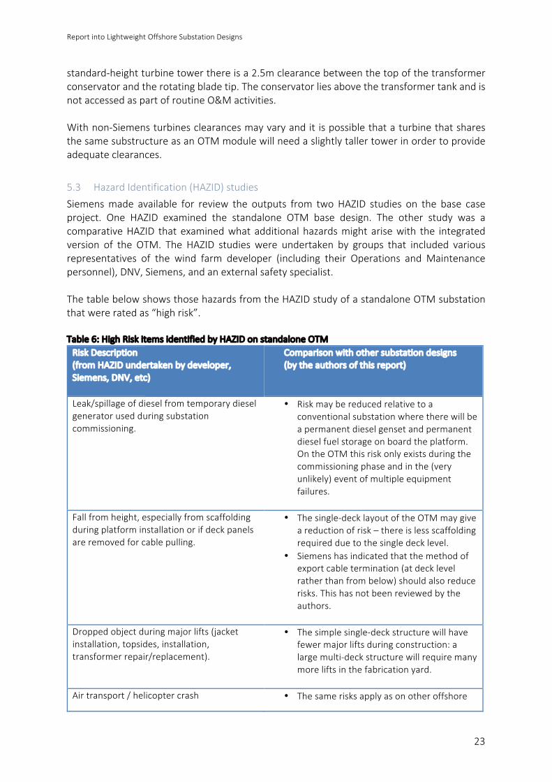
5.3 HazardIdentification(HAZID)studiesSiemensmade available for review the outputs from twoHAZID studies on the base caseproject. One HAZID examined the standalone OTM base design. The other study was acomparativeHAZID thatexaminedwhat additionalhazardsmight arisewith the integratedversion of the OTM. The HAZID studies were undertaken by groups that included variousrepresentatives of the wind farm developer (including their Operations and Maintenancepersonnel),DNV,Siemens,andanexternalsafetyspecialist.ThetablebelowshowsthosehazardsfromtheHAZIDstudyofastandaloneOTMsubstationthatwereratedas“highrisk”.Table6:HighRiskitemsidentifiedbyHAZIDonstandaloneOTMRiskDescription(fromHAZIDundertakenbydeveloper,Siemens,DNV,etc)
Comparisonwithothersubstationdesigns(bytheauthorsofthisreport)
Leak/spillageofdieselfromtemporarydieselgeneratorusedduringsubstationcommissioning.
• Riskmaybereducedrelativetoaconventionalsubstationwheretherewillbeapermanentdieselgensetandpermanentdieselfuelstorageonboardtheplatform.OntheOTMthisriskonlyexistsduringthecommissioningphaseandinthe(veryunlikely)eventofmultipleequipmentfailures.
Fallfromheight,especiallyfromscaffoldingduringplatforminstallationorifdeckpanelsareremovedforcablepulling.
• Thesingle-decklayoutoftheOTMmaygiveareductionofrisk–thereislessscaffoldingrequiredduetothesingledecklevel.
• Siemenshasindicatedthatthemethodofexportcabletermination(atdecklevelratherthanfrombelow)shouldalsoreducerisks.Thishasnotbeenreviewedbytheauthors.
Droppedobjectduringmajorlifts(jacketinstallation,topsides,installation,transformerrepair/replacement).
• Thesimplesingle-deckstructurewillhavefewermajorliftsduringconstruction:alargemulti-deckstructurewillrequiremanymoreliftsinthefabricationyard.
Airtransport/helicoptercrash • Thesamerisksapplyasonotheroffshore

ReportintoLightweightOffshoreSubstationDesigns
24
substations.Notethatheli-hoistisnotexpectedtobethenormalaccessmethod,thoughthiswillultimatelybeadecisionfortheOFTOO&Mstrategy.
Slips/fallscausedbywateroriceondecks • Unlikesomeoffshoresubstations,virtuallyalloutdoorwalkwaysontheOTMhavegratedsurfaces.Thisissaferthansmoothfloorswhichhaveahigherriskofwaterpondingorformingicesheetsincoldweather.
Electrocution,withcabletrappedchargebeingreferencedasaparticularconcern.
• Thesamerisksapplyasonotheroffshoresubstations.
Electricalfiresinequipment,withbatteriesbeingreferencedasaparticularconcern.
• Thesamerisksapplyasonotheroffshoresubstations.
• TheOTM’scontrolcontainer(whichincludesthebatteries)andtheMVcontainerhavegaseousfiresuppression.
Manualhandlingofheavymaterials/equipment.
• Thesamerisksapplyasonotheroffshoresubstations,butthereducedamountofequipmentontheOTM(e.g.nodieselgenset,nofirewaterpumps)shouldreducetheamountofequipmentthatmightneedhandlingforrepairorreplacement.
Ascanbeseenfromthetableabove,allofthekeyrisksassociatedwiththestandaloneOTMareequallyormoreapplicabletolarger“conventional”offshoresubstations.Siemensalsoprovided theauthorswith theoutputof aComparativeHAZID that aimed toidentifyrisksthatwerespecifictotheintegratedversionoftheOTManddidnotariseinthestandaloneversion. TheHAZID identified threeareaswherematerial additional risksmightexist:objectscouldbedroppedfromthewindturbineduringinstallationormaintenance,icemightdropfromthewindturbinebladesduringoperation,andanyfireonthesubstationcouldbeadangertoanypersonsinthewindturbineatthetime.Foralloftheseissues,however,mitigating measures were identified, and both Siemens and the developer involved wereconfidentthatthesemitigatingmeasureswouldhavebeensuccessfullyappliedhadadecisionbeenmadetoproceedwiththeintegratedversionoftheOTM21.TheresultsofthisComparativeHAZIDaredescribedfurtherinConfidentialAppendixB.
21 Thedeveloper in questionultimately decidednot toproceedwith the integrated version and selected the standaloneversion.Howeverthiswasnotduetosafetyconcernsbutduetoconcernsregardingtheadditionalcontractualinterfaces–seeSection7.7.
ReportintoLightweightOffshoreSubstationDesigns
25
6 ISSUESANDMITIGATIONS–RELIABILITY,AVAILABILITY&MAINTAINABILITY
This sectiondescribes thepoints thathavebeen raised (by theauthorsorbyotherOWPBmembers)inrelationtothereliability/availability/maintainability(RAM)oftheOTMconcept,andexplainshowtheseissueshavebeendealtwithbySiemens.
6.1 ImpactofTransformerFaultsUnlikethevastmajorityofoffshoresubstations(butliketheother“lightweight”conceptsfromABBandDONG),theOTMcarriesonlyasinglemaintransformer.Thequestionthereforearisesofwhatwouldhappenshouldthissingletransformerfail.Itisimportanttonotethatthesizeofmodernwindfarmsissuchthat–evenwithitscapacityof 290MW – a single OTMwould not be sufficient to connect any of the UK wind farmscurrentlyunderconstructionorwithsecuredCfDs22.ItisthereforemorerelevanttoexaminethesituationwheretwoOTMsaredeployedtoconnectanoffshorewindfarm.InthiscaseeachoftheOTMscanprovideadegreeofbackuptotheother.Thiscanbedoneinoneoftwoways:
i) If the OTMs are some distance apart then it may be appropriate to provide anormallyopenconnectionbetweenastringofturbinesthatnormallyfeedsoneoftheOTMsandanadjacentstringofturbinesthatnormally feedstheother.Ataminimumthiswillprovideameansofsupplyingwindturbineauxiliarysystemsintheeventofatransformerfault.Withseveralsuchconnectionsandhighercapacityarraycables itmaybepossible for thewind turbines thatusually feed theOTMwhosetransformerhasfailedtocontinuetooperatenormallyattimesoflow-to-mediumwindspeed.
ii) Alternatively,thetwoOTMsmaybedirectlyconnectedbyrunningmediumvoltagecablesbetweenthem.Withcablesofsufficientcapacitythisbecomeselectricallyequivalent to a single conventional substation with two transformers. Thisapproach ismost likely tobeeconomicwhen the twoOTMsare close together(reducingthecostoftheinterconnectingcables)orwherethearrayvoltageis66kV(whichwillgivefewerinterconnectingcablesandmuchlowerper-MWcablecosts).
Thisisdealtwithfurtherinsection8(costreduction)below.TheSQSS(SecurityandQualityofSupplyStandard)foroffshorewindconnectionscontainsarequirement for at least two transformers be used on wind farms of more than 90MW.NationalGridhasrecentlypublishedanote23clarifyingthatthismeansthatthereshouldbeatleasttwotransformersservingawindfarm;thesetransformersdonotnecessarilyneedtobeonthesameplatform.Thedual-OTMapproachdescribedaboveisthereforefullycompliantwiththeSQSS.
22BurboExtensionisanexception–butevenhereasingle-transformerOTMcouldhavebeenusedwith33kVinterconnectionstotheoriginalBurbowindfarmprovidingadegreeofredundancy.
23 See “GuidanceNote -Useof SingeTransformerOffshorePlatforms forOffshoreGenerationConnectionsGreater than90MW”byGSR020WorkingGroup.Alsotheassociatedreportandopenletter.

ReportintoLightweightOffshoreSubstationDesigns
26
6.2 ExperiencewithSyntheticEstersThereislimitedexperiencewiththeuseofsyntheticesterssuchasMidel7131asacoolant/insulant for transformers at 220kV and above: M&I Materials, Midel’s manufacturer, hasprovidedareferencelistwhichshowsonlyasingletransformerin2004andtwounitsin2010.In 2013-14, however, National Grid undertook a research project where a test article (a“representativesampleofafullsizewinding”froma400/132kVtransformer)wasimmersedinMidel7131andsubjectedtolightningimpulsetesting.BasedonthisNationalGridgainedsufficient confidence inMidel 7131 that it ordered threeMidel-filled 240MVA 400/132kVtransformersfromSiemens,andthesearecurrentlybeinginstalled.ThisseemstoconfirmthattheuseofMidel7131at220kVshouldnolongerbeconsideredtechnologicallyrisky24–atleastformanufacturerswithrelevantexperienceinusingthematerial.Windfarmdeveloperswereaskediftheyknewofparticularreasonsforthenon-useofester-filledtransformersonpreviousoffshoresubstationprojects.Noreasonswereidentifiedotherthanlackofexperiencewiththisclassofcoolant.
6.3 OffshoreLogisticsTheOTMbasedesignprovidesforpersonnelaccesstotheoffshoresubstationbycrewtransfervessel,awalktoworksolution(Ampelmann)andaheli-hoist.Ingeneral,theguidingprincipleisthattheoffshoresubstationshouldbeaccessiblebythesamemeansasthewindturbinetowers.Nohelideckisprovided,whichisconsistentwiththedesigndecisionsmadebyalmostallUKoffshoresubstations,butdiffersfromthenorminGermanyandDenmark.IntheNetherlandsTenneThasanalysedtheneedforahelideck25andconcludedthattheextracost(€3-4mcapex,plusadditionalopex)cannotbejustifiedasthereareonlylimitedcircumstancesinwhichthepresenceofahelideckwillacceleraterepairs,i.e.whereheavyequipmentisnotrequiredforthe repair, and where weather conditions are adequate for helicopters but not for crewtransfervessels.TenneT’sconclusionisconsistentwithSiemens’sapproachtoOTMaccess.ThebasedesignOTMsaretobeequippedwithcranesthatwillbeableto:
i) LiftatemporarydieselgeneratorfromacrewtransfervesselshouldmultiplecableortransformerfaultscausethelossofallauxiliarypowerontheOTM.(Thiswouldinvolvethecrewtransfervesselprovidingelectricalpowertothecraneorthecranebeingoperatedmanually).
ii) Liftreplacementradiatorunitsfromacrewtransfervesselshouldreplacementbeneeded (see 6.6 below), and lower the replaced radiator units down to a crewtransfervessel.Thisallowsallradiatorunitstobereplacedusingonlyoneofthewindfarm’screwtransfervessels.
24Giventherelativenewnessofsyntheticestersatthesevoltages,however,windfarmdevelopersmayneverthelesswishtoapplyadditionalmonitoringtotransformerdesign,manufactureandtesting.
25SeeTenneTpositionpaperT.4“AccesstoPlatform”.
ReportintoLightweightOffshoreSubstationDesigns
27
Onmostconventionaloffshoresubstationsthecraneissizedtolifteventheheaviestspareparts (otherthanmaintransformersandshuntreactors)thatmightneedtobebroughtonboard.SiemensintendstoundertakestudiesatthedetaileddesignstagethatwilldeterminethedetailedplatformcranespecificationforthebaseOTM,andhencetherangeofsparepartsthatcanbeliftedonboardtheplatformwithoutanexternalcrane.BecausethebaseOTM’sdetailedcranespecificationhasyettobedrawnup,itisnotcurrentlypossible to determine whether insufficient platform crane capability could lead to arequirementforanexternalcranetoundertakecertainrepairs,whichcould inturn leadtothese repairs taking longer on the OTM than on a conventional substation. In any event,SiemenshaveconfirmedthattheycanprovideanOTMversionwithanupratedcraneshouldcustomersconcludethatthisisdesirable.
6.4 SpaceforMaintenanceandRepairsSiemens have confirmed that clearance around the switchgear and control panels formaintenance,testingandrepairisinlinewiththeirownmanufacturer’srecommendationsforonshoreinstallationsandtheirpreviouspracticeforoffshoreinstallations.Siemenshaveconfirmedthat theMVswitchgearcontainerandthecontrolcontainerallowrepairstobeexecutedwithinthecontainer.Thiscaninvolveeitherremovingandreplacingtheaffectedelements (e.g. individualMVswitchpanels)or their repair in situ. In thecaseofaparticularlyseriousfailuretheentirecontainercanberemovedandreplaced.The220kVswitchgearcontainerdoesnotincludeagantrycrane.AtthedetaileddesignstageSiemenswillinvestigatehowtoundertakesmallerrepairs(e.g.replacementofaVT)withoutthe gantry crane. Should the switchgear be seriously damaged the roof of the 220kVswitchgearcontainercanberemovedbyanexternalcranetofacilitaterepairorreplacement.Spacehasbeenprovidedtofacilitatetransformercoolerreplacement.Thisisdescribedfurtherinsection6.6below.
6.5 OFTO/GeneratorSegregationSomeUKoffshorewindfarmshavemadeparticulareffortstosegregateOFTO-ownedandgenerator-ownedequipmentintoseparaterooms.TheOTMbasedesignsdonotmakeprovisionforseparaterooms,althoughtheydoaccommodateOFTOandgeneratorequipmentinseparatelockablepanels.SimilarlysomeUKoffshorewindfarmsprovideseparatesubstationcontrolsystems26forOFTOownedassets(typicallythehighvoltageswitchgear,transformersandplatformservices)andthegeneratorownedassets(typicallythemediumvoltageswitchgearontheplatformandoneachturbine).Whilemoreexpensive,thisarrangementavoidstheneedforonepartytohaveaccesstotheother’ssubstationcontrolsysteminordertocontroltheirownassets.WeunderstandthatinthebaseOTMdesign,asinmostolderUKsubstations,26Thesubstationcontrolsystemsarefrequentlycalled“SCADAsystems”.Thisterminologyisnotusedhereinordertoavoidconfusionbetweenthesubstationcontrolsystems(whichareusuallybasedontheIEC61850standard)andthewindturbineSCADAsystem.

ReportintoLightweightOffshoreSubstationDesigns
28
onlyasinglesubstationcontrolsystemisprovided.SincethemajorityofUKoffshoresubstationsaremaintainedandoperatedbythehostwindfarm,undercontracttotheOFTO,thereisarationaleforreducingcostandconstruction-stagecomplexitybyprovidingonlyasinglesubstationcontrolsystem.However,whetherornotthehostwindfarmwillundertaketransmissionO&MwillnotbeknownuntilafteranOFTOhasbeenappointed,andanumberofwindfarmdevelopershaveexpressedastrongpreferenceforsegregatedsubstationcontrolsystems.SiemenshasconfirmedthatthereissufficientpanelspaceintheOTM’scontrolcontainertoallowtwosubstationcontrolsystemstobefitted(nearlyalloftheextraequipmentwouldbeonshore). They can, therefore, offer segregated generator and OFTO substation controlsystemstocustomersasanoptionalextra.
6.6 CorrosionTheoffshoreenvironmentishighlychallengingfromthepointofviewofcorrosion.Aparticularissueislikelytobethetransformercoolerswhicharedifficulttorepaintinthefieldandwherethemetalmustbethintoallowefficientheattransfer.Siemenshavemitigatedtheimpactoftransformercoolercorrosionbyallowingcoolerstobereplaced easily should this become necessary. This is not always the case on offshoresubstations,withmany requiring an external crane to remove the transformer room roof,and/orlackingvalvestoshutdownindividualcoolers,sothatthewholecoolerbankmustbereplacedasasingleunitbyanexternalcranewhilethetransformerisoutofservice.Siemenshasshowntheauthorsa“storyboard”describinghowindividualcoolerbankscanbeisolated,drainedofoil,loweredtothedeck,movedtotheplatformcraneandthenloweredtoacrewtransfervessel,whilereplacementcoolersare installedbyreversingthisprocess.Coolerreplacementcanbeundertakenoneunitatatimewithoutneedingtoshutdownthetransformer,andtheprocessshouldnotrequireanyshipsotherthanastandardcrewtransfervesselstodeliverorliftreplacementpartsortools.
6.7 AuxiliaryPowerAuxiliarypowerfortheOTMcanbetakenfromoneofthreepossiblesources:
i) Innormaloperationauxiliarypoweristakenfromtheearthing/auxiliarytransformerwithinthemaintransformertank.
ii) Shouldthemaintransformerfail,orneedtobetakenoutofserviceforroutinemaintenance,
thenthenormallyopenMVconnectionsbetweentheaffectedOTMandotherOTMswithinthesamewindfarm(seesection6.1)canbeclosed,re-energisingthesubstationMVbusbar.Substationauxiliarypower is thenmaintained through theauxiliary transformer in theMVcontainer.
iii) Intheeventofacompletegridfailurethataffectsallofthewindfarm’soffshoresubstations
(e.g.ananchordragthatdamagesallexportcables)atemporarydieselgeneratorcanbelifted
ReportintoLightweightOffshoreSubstationDesigns
29
ontotheOTM’sdeckandpluggedintothe400Vswitchboard.Asnotedinsection6.3above,theintentionisthatthisoperationcanbeundertakenusingonlyacrewtransfervesselandtheplatform’sowncrane.Thistemporarygeneratorwouldalsobeusedduringcommissioning.
TheabsenceofapermanentlyinstalledstandbydieselgeneratoronboardtheOTMisasignificantdifferencefromallexistingUKoffshoresubstations,andallnon-UKoffshoresubstationsknowntotheauthors. Bymaking use of interconnectors to other OTMs in the same wind farm, however, thecircumstancesunderwhichapermanently installeddieselmightberequiredbecomevery limited.Indeeditislikely,giventheknownreliabilityproblemsofdieselgenerators,thattheauxiliarypoweronboardanOTMthatisinterconnectedtoaneighbouringOTMwouldbemorereliablethanwouldbe the case on board a conventional substation with a single export cable and a backup dieselgenerator.Basedonthehighlevelofauxiliary-powerreliabilityexpectedthankstobeingabletodrawpowerfromneighbouringOTMs,combinedwiththeabilitytoliftanemergencygeneratorontotheOTMintheeventofanextremefailure,theauthorsconcludethatnothavingadieselgeneratoronboardtheOTMisacceptable.Theyalsonotethatremovingthegenerator(anddieselfuel)fromtheplatformisexpectedtogivesignificantreductionsinO&Mcostandcomplexity.
6.8 CablePull-inSiemenshaveundertakenaconsiderableamountofworkplanningthepull-inofcablestotheOTMinordertoconfirmthattheprocesswillnotbeaffectedbythesizeoftheOTM’scabledeckarea,whichissmallerthaninmostconventionaloffshoresubstations.Theauthorsweregivenaccesstodetailedstoryboardsillustratingtheproposedpull-inprocess.Theseshowedthepull-inwinchmountedonthemaintopsidesdeck,withthepull-inwirerunningtothetopofaJ-tubeoverpulleys(somemountedontemporaryA-frames)andthroughslots inthetopsidesdeckwhichwouldbecoveredbygratingsinnormaloperation.Inaddition,tosimplifythepull-inandterminationofthe220kVexportcablethe220kVswitchgear’scableterminationsarenotvertical(theusualarrangement)butangledat45°.

ReportintoLightweightOffshoreSubstationDesigns
30
7 OTMSTRUCTURALDESIGN
TheOTMconceptcanbeusedwithanumberoftypesofsubstructure:theprincipleisthatrather than having a custom-designed substructure the OTM should sit on a substructureadaptedfromwhateverhasbeendesignedfortheturbines inthewindfarmservedbytheOTM.InthiswaytheOTMcantakeadvantageoftheeconomiesofscalecreatedbythe“massproduction” of substructures for the wind turbines (typically there might be 40 or moreturbinesforeveryOTM27).The large number ofwind turbine substructures producedmeans that decisions regardingsubstructuretype,weightandstiffnesswillbedrivenbytheneedtominimisethecostofwindturbinesubstructures.Thesubstructuredesigner28willthenhavetotakeasubstructurethathasbeenoptimisedforwindturbineserviceandadaptittheserveastandaloneOTMoranintegratedcombinationofturbineandOTM.Fortunately,Siemens’sexperiencetodate–andtheir expectation for the future – is that this adaptation of the substructure designwon’tinvolvesignificantweight increasesorsignificantchangestothefabricationand installationworks.
7.1 StandaloneOTMonJacketSubstationSubstructureIt iscurrentpractice forsubstationsubstructurestobebuiltwithhighersafety factors (the“designfatiguefactor”,see7.3below)thanwindturbinesubstructures.However,thedynamicloadingimposedbytheOTMissomuchlowerthanthatimposedbya7-8MWwindturbinethat–evenifthehighersafetyfactortypicallyappliedtosubstationsisused–itisstillpossibletoaccommodatetheOTMontheessentiallysamedesignofjacketastheturbinesinthesamewindfarm.TheOTMbasedesignsweredevelopedonaprojectwhereafourleggedjacketsubstructurehadalreadybeenselectedastheoptimumforthewindturbines.Thesejackets,whichstandindepthsofaround45m,weighabout800-900tinbothwindturbineandOTMvariants.WhilesomeworkontheOTMjacketdesignisstillongoing(forinstancedifferentoptionsarebeingexploredfortheJ-tubes29andfortheconnectionbetweenthejacketandtheOTM)Siemenshas been able to confirm that these issueswill not lead to significant changes in the size,framingandinstallationoftheOTMjacketrelativetothewindturbinejackets;thisensuresthattheexpectedeconomiesofscalecanbeachieved.
7.2 IntegratedOTMonJacketSubstructure(sharedwithWindTurbine)The integrateddesignmakesuseofa layoutwhereallequipment ismovedaway fromthecentreofthetopsidesdeck,leavingspaceforacircularholethattheturbinetowerislowereddownthrough.NotethatthereisnoconnectionbetweentheOTMtopsidesdeckandthewind
27290MW-per-OTMdividedby7MW-per-turbine28 It islikelytobemostcosteffectiveifthecompanythathasdesignedthewindturbinesubstructuresalsoworksoutthemodificationstothesubstructuredesignneededforOTMservice.
29SinceasubstationhasmanymorecableconnectionsthanawindturbinethesubstructureforthesubstationmustsupportasignificantlylargernumberofJ-tubes.TheJ-tubesmustbecarefullyarrangedsothattheirsupportsdonotoverstressthejacketbracing,andevenwiththiscarefularrangementcertainkeyareasofthejacketmayneedtobestrengthened.

ReportintoLightweightOffshoreSubstationDesigns
31
turbine;insteadtheturbineissupporteddirectlyonthejackettransitionpiece,asisthecaseforthe“regular”turbinesinthewindfarm(i.e.thosethatdon’tshareasubstructurewithasubstation).ThejacketsusedbytheintegratedOTMbasedesign,thestandaloneOTMbasedesignandtheturbinesinthewindfarmforwhichthebasedesignwasdevelopedareallverysimilarindesignandweight.Thefactorofsafety(“designfatiguefactor”)usedinvalidatingthesubstructuredesign,however,variesbetweenthethreeroles.Thisisdiscussedfurtherinsection7.3below.The extent of movement and acceleration that would be experienced by high voltageequipment on the integrated OTM was analysed by the base case project’s substructuredesigner.ThesecalculationsindicatedthatthepeakaccelerationsonthebaseintegratedOTMwouldbe less thanona conventionalmonopile-supported substation. IndeedSiemenshassupplied equipment to one monopile-supported offshore substation where the peakaccelerationsarenearly3timesgreaterthanthevaluepredictedforajacket-supportedOTMwithintegratedwindturbine.TheaccelerationvaluescalculatedbythesubstructuredesignerareprovidedinConfidentialAppendixC.
7.3 DesignFatigueFactorFatiguedesignofsteelstructuresisusuallybasedontheuseofS-Ncurves(i.e.curvesplottingS,thelevelofcyclicalstressappliedtoamaterial,againstN,thenumberofcyclestoagivenprobabilityoffailure).Thesecurvesareusedtocalculateafatiguelifebasedontheloadingspectrum that the structurewill see. A design fatigue factor (DFF) is then applied to thecalculatedfatiguelife,withthisfactordependantontherequiredsafetylevelofthestructure,andtheabilitytoinspectthejointforwhichthefatiguelifeisbeingcalculated.DNV-OS-J101isthestructuraldesigncodemostcommonlyadoptedforthedesignofoffshorewind turbinesubstructures. This codespecifies thataDFFof3 shouldbeadopted for thefatiguedesignofwindturbinesubstructuresinlocationswherenoinspectionisplanned.Thisgivesanannualprobabilityoffailureof10-4,whichisconsideredappropriateforanormallyunmannedstructure.DNV-OS-J201 is the DNV design code usually used for offshore substations and theirsubstructures. This code specifies that aDFFof 10 shouldbeused in thedesignof thesestructures in locations where no inspection is planned. This corresponds to an annualprobabilityoffailureof10-5,anorderofmagnitudelowerthanforthewindturbine30.Asnoted in theprevious section, the jacketsusedby the integratedOTMbasedesign, thestandaloneOTMbasedesignandtheturbinesinthewindfarmareallverysimilarindesignbuthavedifferentDFFsapplied:
30TherationalebehindusingaDFFof10foranoffshoresubstationisnotexplainedinDNV-OS-J201.Itisinterestingtonotethatinotherdesigncodes(mostnotablyAPIRP2A,whichispredominantlyusedbytheOilandGassector),theuseofaDFFof10isrecommendedfor“failurecritical”structures–acategorybasedontheprobabilityofpersonnelinjury/fatalities–andtheDFFcangenerallybereducedto5forunmannedstructures.

ReportintoLightweightOffshoreSubstationDesigns
32
i) ForjacketsusedbywindturbinesaDFFof3isused,inlinewithDNV-OS-J101.
ii) ForjacketsusedbystandaloneOTMsaDFFof10isused,inlinewithDNV-OS-J201.
iii) ForjacketssharedbywindturbinesandintegratedOTMsusingaDFFof10would
resultinacirca45%increaseintheintegratedOTM’sjacketweight,whichcouldmakeitimpossibletoinstallusingthesamevesselasthewindturbinejackets.AsaresultofthisareducedDFFof6wasselectedfortheintegratedOTM’sjacket:thisallowstheintegratedOTM’sjackettobebuiltwithonlyminorchangesfromthestandardturbinejacketandatweightthatisonly10-15%higher31.
SiemenshasdiscussedusingaDFFof6withDNV,whohaveprovidedaletterinrelationtooneoftheprojectsthatSiemensareworkingonconfirmingthattheywouldcertifyadesignbasedonthisDFFprovidedthat:
i) ThewindfarmcontainsmorethanoneOTMwithsomedegreeofredundancy.(Asnotedinsection6.1,thisisexpectedtoalwaysbethecaseforfutureBritishwindfarms–althoughsomewindturbinestringscouldbedisconnectedifanOTMweretobecompletelylost).
ii) ThelowerDFFisacceptabletotheclient.(WeunderstandthatthelowerDFFwasnotaconcernfortheprojectdeveloper;certainlyitwasnotraisedasaconcernintheHAZIDstudies).
iii) The OTM is normally unmanned. (The OTM concept includes no provision forpersonsstayingonboardforlongerthanasingleworkshift;theemergencyrefugeisstrictlyforemergencyuseonly).
7.4 IntegratedOTMonMonopileSubstructure(sharedwithWindTurbine)A preliminary engineering studyhas been carriedout by an experienced turbinemonopiledesignertochecktheeffectofaddingsubstationtopsidestoawindturbinesupportedbyamonopile substructure. Substation topside weights ranging from 250t to 1300t wereconsidered,andrepresentedbyamassaddedtothefiniteelementmodelofamonopileinwater approximately 30m deep, with a 6MW Siemens wind turbine and sandy soil beingassumed.Theresultssuggestedthatfora1090tsubstationtopsidetherewouldbeanincreaseof13%(1487tto1687t) inthemonopileweightandanincreaseinmonopilediameterfrom8mto8.2m.Therewouldbeonlyaverysmallchangeinthefirstnaturalfrequencyofthestructure,andwhiletherewouldbeamoresignificantchangeinthesecondnaturalfrequency,itwouldnotbesufficienttotakethenaturalfrequencyoutsidetherangerequiredbythewindturbinemanufacturer.Itshouldbenotedthat,asthefocusofthisstudywasonchangestonaturalfrequency,noincreasetoDFFwastakenintoaccountabovetheDFFof3normallyspecifiedfor awind turbine.Norwas considerationgiven to the impactof themultiple J-tubes that31Weightcalculationswereundertakenbythesubstructuredesignerretainedbythebaseproject’sdeveloper.
ReportintoLightweightOffshoreSubstationDesigns
33
wouldberequiredbyasubstation.This initial work is encouraging in suggesting that an integrated OTM could work with amonopilesubstructure.Nevertheless,anydeveloperwishingtopursuethisoptionwillneedtoundertakeafullfeasibilitystudyusingsite-specificdata(preferredturbineparameters,waterdepth,metocean,geotechnical,etc).Fornewprojectsthisstudycanbeincorporatedintothestructural design studies that will be required in any event to identify the optimumwindturbinesubstructures.Aparticularconcernhasbeenraisedoverthemovementsandaccelerationsthatequipmentplacedonamonopilestructurewithawindturbine.Thiswillneedcarefulconsiderationandcollaborationbetweenelectricalequipmentmanufacturersandstructuraldesignerstoensurethe forces equipment is subject to over its lifetime are tolerable. The Offshore WindProgramme Board has funded a basic study by ORE Catapult that analyses accelerationsrecorded at the wind turbine tower-base level where any substation topsides would besituated.
7.5 SubstationTopsidesStructureThetopsidesstructurefortheOTMbasedesignweighsatotalof660tonnes.Withthe320MVAtransformerabletoacceptupto290MWofwindpowerthisgivesthedesigna“powerdensity”of440kW/tonne–substantiallybetterthananyotheroffshoresubstationforwhichweightinformation has been found, and 75% better than the best project in table 4 with“conventional”enclosedtransformerrooms.It should be noted that this lowweight is not driven by a reduction in theweight of the“payload”(themechanicalandelectricalequipmentonboardtheplatform):most(c.85%)ofthepayloadweightonanyoffshoresubstationisthetransformers(andshuntreactors,ifany),and the OTM’s transformers are not particularly light on a per-MVA basis32. Similarly, thesimplificationofauxiliaryequipmentwillnotchangethepayloadweightsignificantlysincethisequipment is not amajorpart of the total payloadweight: a 100kVAdiesel generator, forinstance,onlyweighsslightlymorethanonetonne.InsteadthesourceoftheOTM’sexcellentpowerdensityisthelowstructuralweightofthetopsidesrelativetothepayload.OntheOTMtheweightofthetopsidestructureisabout75%oftheweightofthepayload(iftheweightofthecontainersisincludedwithinthestructure),or50%oftheweightofthepayloadiftheweightofthecontainersisincludedinthepayload33.Onatypicalconventionalsubstation,incontrast,thestructuralweightwouldbearound150%to200%ofthepayload.Intheopinionoftheauthorsthisreductioninstructuralweightrelativetothepayloadweightmaybeattributedtoanumberoffactors,including:32Aswasnotedpreviously,largertransformerstendtohavealowerweightperMVA.ThisphenomenonisnotvisiblewiththeOTMtransformerwhenitsweightiscomparedtotransformersonconventionalsubstations.Thismaybeduetoitsuseofestercoolant,orbecauseithasnocoolingfansorpumps.
33 Hence for outdoor equipment, like the transformers, the topsides structural weight adds 50% to the weight of theequipment.

ReportintoLightweightOffshoreSubstationDesigns
34
i) There is a very large reduction inenclosedvolumecompared toa conventional
“multideck”offshoresubstationwithenclosedorpart-enclosedtransformers.Forinstance, one recent substationwith two large transformerswas examined andfound tohavea totalenclosedvolumeofnearly2000m3per transformer.Morethanhalfofthisofthisrelatestothetransformerrooms:ontheOTMthisvolumeiseliminatedentirely.TheremainingvolumeisreducedbyaquarterontheOTMby eliminating the diesel generator room, store rooms, work stations, akitchen/mess-room,atoilet/wash-roomandalockerroom.
ii) The single-deckOTMdesign is less rigid thanamultideckplatform.Rather thanaddingweight to reduce this flexibilitySiemenshavedesigned theOTMdeck toaccommodate a degree of flexibility while still ensuring that deflectionrequirements are met during all loading conditions. Where deflections arepredicted these have been accommodated through, for instance, making thetransformerhighvoltageconnectionusingflexible220kVcablesratherthanrigid220kV gas insulated busbars, and using bearing contacts and stiff subframes tosupportequipmentthatneedstoberigidlymounted.
iii) Siemenshasbeenabletospendlongeronoptimisingthedesignthanisusualfor
wind farm substations: there is anecdotal evidence that structural designfrequentlyneedstobeundertakeninacceleratedtimescales,leadingtosimpler–butheavier–solutionsbeingadopted.
7.6 VerifyingtheFeasibilityofanOTMwithShuntReactorsAsnotedinsection4.2,oneoftheOTMversionsavailablefromSiemensincorporatesashuntreactor.DiscussionswithintheOffshoreWindProgrammeBoardhaveindicatedthatthisisanimportantfeatureformanywindfarmdevelopers.InordertoverifythatashuntreactorcanbeaccommodatedwithouttheweightoftheOTMtopsidesreachingthepointatwhichmorethanoneliftwillberequired,theauthorsundertooka brief proof-of-concept analysis. It was assumed that a 90Mvar shunt reactor would berequired,asthisisthesizeincludedintheDONGdistributedsubstationconcept.Theauthorsdonothaveaccurateinformationontheweightofa90Mvarester-filledshuntreactor,butbyscalingfromonshoreshuntreactorsitwasconcludedthatarangeof100-120twaslikely.Adding50%tothisweighttoaccountfortheadditionaltopsidesstructurerequiredtosupportthereactorgivesatotaladditionalweightof150-180t.Addingthistothe660ttotalweightofthebaseOTMdesigngivesatotalestimatedweightforanOTMwithashuntreactorof810-840t.Theestimatedweightisbelow(ifrathercloseto)theestimatedmaximumweightthatcouldbeaccommodatedbyallnominally“1000tonne”cranes(seeSection3).Itshould,therefore,bepossibletoinstallanOTMwithashuntreactorwithoutneedinganyadditionalheavy-liftoperations34.34ThoughgiventhescaleofthecostsavingsshowninSection8,therewouldonlybealimitedimpactontheeconomicbenefits

ReportintoLightweightOffshoreSubstationDesigns
35
7.7 ContractualInterfaceConsiderationsOnpreviousUKprojectsthedesignandbuildoftheoffshoresubstationhasbeenundertakenusingawiderangeofcontractualapproaches,withmulti-contractarrangements(wherethesubstationtopside,substationsubstructure,heavy-liftandsometimesmajorelectricalitemsarecoveredbyseparatecontracts)beingmostpopular.Thereissomeanecdotalevidencethatthealternative“turnkey”approach(wheresubstationtopsides,substructuresandinstallationareintegratedintoasinglecontract)isbecomingmorepopularfornewoffshoresubstations,presumablybecauseofthesimplificationandreductionofcontractualinterfaces.AsnotedinSection3.3above,lightweightsubstations(includingtheOTM)tendtocutacrosstheturnkeyapproach:
i) ItislikelytobemorecosteffectivetohavetheOTMsubstructuresdesigned,builtand(whereapplicable)installedbythewindturbinesubstructurecontractorwhoisalreadyundertakingthisworkonmaybe70-80othersubstructures.Suchsavingscanbeexpected tomore thanoffsetany impact from introducinganadditionalcontractualinterface.
ii) TheOTMconceptinvolvesusingthesameheavy-liftvesselstoinstallthesubstationandthewindturbines.Thereductioninprogrammeriskthatthisprovides(sincetheheavyliftvesselusedforsubstationinstallationwillbeavailableonsiteforaprolongedperiodratherthanforanarrowwindow)isexpectedtofaroutweighanyimpactfromintroducinganadditionalcontractualinterface.
Where the substation topsides and awind turbine are being accommodated on the samesubstructuresomeadditionalcomplexitiesarise:
i) Siemens’s OTM base design is based on using a Siemens 7MW wind turbine.However, Siemenshave stated that thehole in themiddleof the topsidesdeckcouldbereducedor increased insizetoaccommodateanyof the7–8MWwindturbinesthatarecurrentlyonthemarket–includingequipmentmanufacturedbytheircompetitors.Itshouldbenotedthatthereisnophysicalconnectionbetweenthewindturbineandthesubstationtopsides:thewindturbineconnectsdirectlytothesubstructure.
ii) The substructure design contractor, who might be working directly for thedeveloperorasasubcontractortotheturbinesubstructuresupplier,willneedtoreceivedesigndatafromboththesubstationsupplierandtheturbinesupplier.Itisnoted that there are often sensitivities around such data, particularly if thesubstationandturbinesuppliersarecompetitors.However,itshouldbepossibletoput inplacesuitablenon-disclosureagreementstoensurethatconfidentialdatafromonesupplierisnotpassedtotheother.
iii) Theremaybeliabilityissuesifonecontractorphysicallydamagesassetsprovided
byanother:anextremeexampleofthiswouldbeifapartofturbineweretobe
oftheOTMconceptifitwasnecessarytolifttheshuntreactorseparatelyandterminatethecablestoitoffshore.

ReportintoLightweightOffshoreSubstationDesigns
36
droppedontheOTM.Inpractice,however,suchissuesarelikelytobecoveredbythewindfarmdeveloper’scontractor’sallrisks(CAR)insurance.
iv) Theremaybeliability issuesfromdelays,designissues,orreductioninasset life
thatiscausedbytheprovisionofincorrectdesigndatafromtheturbine,substationorsubstructuresupplier.Anexamplewouldbewhere thewind turbinesupplierprovidesincorrectdataaboutitsturbine,asaresultofwhichtheOTMexperienceshigher long-termmovement and accelerations than expected, with an adverseeffectonelectricalequipmentreliability.
The authors understand that at least one potential customer for the integrated OTM hasinsteadoptedforthestandaloneOTMduetotheissuessetoutabove,andinparticularduetoconcernsregardingtheallocationofliabilityshouldlongtermmovementsandaccelerationsprovelargerandmoredamagingthanforecast.Becauseoftheimportanceofthesecontractualliabilityissuesforwindfarmdevelopers,theOffshoreWindProjectBoard is consideringhowbest tomitigate theseconcerns.An initialpieceofworktohelpdothisistheindependentassessmentundertakenbyORECatapultofthelikelymagnitudeandeffectofthemovementsandaccelerationsthatmaybeexperiencedbyhighvoltageequipmentintheintegratedOTMdesign.Thisshouldhelpguidethedesignofamoreextensivestudythatwouldgivedevelopersgreaterconfidencewhenassessingwhetherthese interface issuesareactuallyproblematicorwhethertheyareaminoradditiontotheinterfacerisksthataredealtwithasamatterofcourseoncurrentwindfarmprojects.

ReportintoLightweightOffshoreSubstationDesigns
37
8 COSTREDUCTION
Siemensandawindfarmdeveloperhavepresentedtoanindustryworkinggroup(knownas“GSR020”)35thefollowingvaluesasanexampleofthesavingsthatcanbeobtainedbyusingtheOTMona500MWwindfarmproject36.Thesavingsareasfollows:
i) Acostreductionof£25m(at2015prices)fromtheuseoftwostandaloneOTMsinplaceofasingle“conventional”substation.Theconventionalsubstationisassumedto be a multi-deck design with flammable-oil-filled transformers, with thetransformers (or at least their tanks) being enclosedwithin transformer rooms.Therearenoshuntreactors.The£25mtotalsavingisthesumofsavingsintopsidesequipment/fabrication, savings in substructure fabrication and savings intransport/installationcosts.
ii) Anoffsettingcostincreaseof£1.5mduetothecostofprovidingcablesbetweenthetwoOTMstoensureadegreeofredundancy.ItissuggestedintheGSR020datathatthesamecostshouldapplywhetherthecablesinquestionarehighvoltage(220kV)ormediumvoltage(33kVor66kV).
TheGSR020groupincludedNationalGridandthreeotherwindfarmdevelopers,andSiemensnotesthatthesecostreductionfigureswereacceptedbytheworkinggroup.
8.1 ImpactofWindFarmSizeIfthenotionalwindfarmbeingservedweretobecomesmallerthanthe500MWchosenherethenthecostsofconventionalandOTMsubstationswouldfallslightly,butnotpro-ratatothereductioninwindfarmMW.ThesavingsprovidedbytheOTMwillsimilarlynotfallpro-ratatothereduction inwind farmsizeandso theper-MWsavingprovidedby theOTMwouldbehigher.
Ifthenotionalwindfarmbeingservedwastobecomelargerthanthe500MWchosenherethen,bythereverseoftheeffectdiscussedabove,theper-MWsavingprovidedbytheOTMwouldreducesomewhat.Itshouldbenoted,however,thatouranalysisdoesnotincludetheimpactof longer array cables andhigher array cable losses– theseare likely tobecomeasubstantialfactorifawindfarmofasmuchas700MW37istobeconnectedtoasinglecentralsubstation.Allexistingprojectsof500MWormorehavetwoconventionalsubstations,eachwithatleasttwotransformers.RelativetoadesignwithtwoconventionalsubstationsthecostsavingfromusingtheOTMconceptwouldbesubstantiallygreater.
35SeeAnnex3ofthereportofworkinggroupGSR020.GSR020isaworkinggroupoftheSQSSReviewPanel.AlthoughtheGSR020 figures relate to a specific project, the fact that theywere accepted by developersworking on other projectssuggeststhattheydonotresultfromunusualsite-specificfactors.Furtherworkwillbeundertakenin2016bytheOffshoreWindAcceleratortoquantifythebenefitsofOTM-typeconceptsacrossarangeofusecases.
36Itshouldbenotedthattheexactsavingswillvaryfromprojecttoprojectduetositespecificfactors.37 For wind farms larger than 700MW the relevant comparisonwould be three OTMs versus one (or,more likely, two)conventionalsubstations.

ReportintoLightweightOffshoreSubstationDesigns
38
Because of the factors listed above, it is thought that the cost reduction calculated for a500MWwindfarmislikelytobeaconservativeestimate,withothersizesofwindfarmlikelytogivesimilarorhighersavings.
8.2 IndependentCalculationofCostSavingsforaStandaloneOTMThissectionseekstovalidatethecostreductionsindicatedabovebyindependentlycalculatingthelikelysavingsfrompublicdomainsources.Thisisdealtwithinthreeareas:transportandinstallationcosts,thecostoffabricatingsubstructures,andthecostoffabricatingthetopsides.TransportandinstallationcostsPublicdomaincostsforanoffshoresubstationareprovidedinthedocument“AGuidetoanOffshore Wind Farm”, published by The Crown Estate and written by BVG with industrycontributions.Thisprovidescostfiguresforawindfarmwith“asinglesubstation[that]cansupporttheinputfromaround500MWofwindturbines”.This cost of “transfer of the substation [topside] from its quayside fabrication site andinstallationonthefoundation”isgivenas£10m38.Thecostofinstallingthesubstationjacketandpilingittotheseabedisnotspecified,thoughsincethecostofmobilisingaheavyliftvesselwouldalreadybeincludedinthe£10mtopsidesinstallationcost,thecostofjacketinstallationwouldpresumablybesubstantiallyless.Forthepurpose of this analysis jacket installation is assumed to cost half as much as topsidesinstallation,i.e.£5m.Thisgivesatotalinstallationcostof£15mfortheconventionalOSP.SincetheOTMwouldtypicallybeinstalledbyavesseldesignedtoinstall7-8MWwindturbines,areasonablestartingpointfortheOTMinstallationcostwouldbetheinstallationcostofan“8MWclass”turbineanditssubstructure,whichhasbeenestimatedas£2.8m39.ThedifferencebetweenthetransportandinstallationcostforapairofOTMs(2x£2.8m)andthatforasingleconventionalsubstation(£15m)istherefore£9.4m.FabricationofsubstructuresAGuidetoanOffshoreWindFarmgivesthecostoffabricatingthejacketandpilesfora500MWconventionalsubstationas£10m40.Thecostofafabricatingajacketsubstructurefora7-8MWwindturbineisestimatedtobe£3m41.TheOTMisintendedtousethesamesubstructuredesignasthesurrounding7-8MW38Source:SectionI5of“AGuidetoanOffshoreWindFarm”.39Source:ScaledfromgraphshownasExhibit3.8in“OffshoreWindCostReductionPathways”,areportbyTheCrownEstatewithindustrycontributions,2012.InstallingtheOTMtopsideswouldrequireonlyasinglelift,ratherthanthemultipleliftsrequiredforaturbine,suggestingalowercost,whiletheneedtoprovidespecialseafasteningsand/ortoprovideaspecialtransportbargefortheOTMdeckwouldincreasecosts.ThisbalanceoffactorssuggeststhatassumingasimilarinstallationcostforturbinesandOTMsislikelytobebroadlycorrect.
40Source:SectionB3.3of“AGuidetoanOffshoreWindFarm”.Curiouslyhelipadsarealsoincludedwithinthiscostcategory,buttheseareveryrareonUKsubstations.
41Source:SectionB2of“AGuidetoanOffshoreWindFarm”,whichstatesthatfabricationofajacket(pluspinpiles)fora

ReportintoLightweightOffshoreSubstationDesigns
39
turbines(withminorchangessuchasadditionalJ-tubes),soitsjacketfabricationcostshouldsimilarlybearound£3mforeachOTM.ThedifferencebetweenthesubstructurefabricationcostforapairofOTMs(2x£3m)andasingleconventionalsubstation(£10m)istherefore£4m.ElectricalequipmentThere is no significant difference in the electrical equipment on the conventional offshoresubstationandontheOTM:ontheconventionalsubstationtherewillbeapairoftransformers,eachwithitsown220kVandMVgear,whilewiththeOTMoptioneachtransformer/switchgearblockisplacedonaseparateOTM.Therearesomeminoradditionswiththetwo-OTMoption,for instance additional auxiliary transformers, but the cost andweight impacts of these isunlikelytobematerial.CostsassociatedwithOTM-to-OTMcablesaredealtwithseparatelybelow.FabricationoftopsidesEachOTMtopsidesweighs660tonnes.Thiscomprisesa“payload”partanda“structure”part,withthestructurepartbeing75%oftheweightofthepayload(seeSection7.5).ItfollowsthatthetopsidesstructuralweightforapairofOTMsis(660x2)x(75%/(100%+75%)),i.e.565t.Asnoted inSection7.5, forawell-designedconventionaloffshoresubstationthestructuralweightistwiceaslargeasfortheOTM:150%ofthepayload(whichisthesame)ratherthan75%. Thus an additional 565t of topsides structuremust be fabricated for a conventionalsubstationthatcontainsessentiallythesamehighvoltageequipmentasapairofOTMs.Thecostoftopsidesfabrication(i.e.thecostofthetopsidesexcludingthecostofthehighandmedium voltage assets and their control& protection systems) is typically in the range of£10k/tonneto£20k/tonne42.Thusfabricatinganadditional565toftopsideswouldcost£5.6-11.3m.Thisincludesboththecostoffabricatingtheextrastructureandthecostoftheextraauxiliaryequipment(e.g.lighting,heating,ventilation)thatscaleswiththesizeofthestructurebeingserved.Inaddition,theOTMdesigncompletelyeliminatesanumberofexpensiveauxiliarysystems,notablythetransformerfireprotectionandthedieselgenerator:
i) NationalGridhasestimatedthatthenetcostsavingfromusingMidel7131(i.e.thereductioninfireprotectioncostslesstheincreasedcostofthetransformeritselfdue to the use ofMidel) is £235k43 per transformer, based on a similar size of
5MWturbinemaycostasmuchas£3m“dependingonwaterdepth”.Unpublisheddata froma studybyORECatapultsuggeststhatthis£3mfigureisalsoreasonablefora7-8MWturbineatmodestwaterdepths.Atgreaterwaterdepthsthesubstructurefabricationcostwillbesomewhathigher.
42PubliclydisclosedexamplesincludethecontractsforAnholt(£14k/t)andHornsRev3(£19k/t).43 See Network Innovation Allowance Project Registration document for “400kV Synthetic Ester Filled Transformer PilotProject”.TheNationalGridcostreductionestimateisbasedononshoreinstallation.

ReportintoLightweightOffshoreSubstationDesigns
40
transformertothatusedontheOTM44.
ii) Adieselgenerator,and itsassociatedfuel,coolingandfiresuppressionsystems,typicallycostsontheorderof£200k.
Thesefactorsincreasetheestimatedcostsavingby£670k(2x£235k+£200k)to£6.3-12.0m.OTM-to-OTMcablesIn a conventional offshore substation the MV switchboards are arranged so that if atransformer,oritsassociatedexportcable,weretofailthentheturbinesthatitnormallyservescanbeconnectedtoanothertransformer.Asthisothertransformerwillnowhavetosupportboththeturbinesitnormallyserves,andtheturbineswhosenormaltransformerhasfailed,itscapacitywon’tbesufficienttoallowfullpoweroutputfromallturbines.Nevertheless,sincewindfarmsspendmostofthetimeatreduced levelsofoutputthisarrangementwillallowconsiderablyhigherenergyexportswhilethefailedtransformerorcableisbeingrepaired.SincetheOTMconcepthasonlyasingletransformeroneachsubstation,providingthislevelofredundancyrequirestheadditionofcablesbetweentheMVswitchboardsineachOTM.Where standaloneOTMs areused, andwhere the array cables from thewholewind farmconvergeatasinglepoint (as is impliedhere,since thecost impactofarraycablechangesbetweenthetwin-OTMoptionandthesingleconventionalsubstationarenotdiscussed), itshouldbepossibletoplacethetwoOTMsbesideeachother:indeedtheycouldprobablybebridge-connected45.InthiscasethecostofconnectingthetwoOTMsshouldbeminimal.
8.3 IndependentCalculationofAdditionalCostSavingsforanIntegratedOTMIf an integrated design is adopted where wind turbines share the offshore substation’ssubstructures then these turbines don’t need to provide their own substructures or arraycables,withconsiderablesavings.However thetwoOTMscanno longerbe locatedbesideeachothersincetheturbineswillneedtorespectthearrayspacing;hencethecostofOTM-to-OTMcableswillincrease.WindturbinesubstructuresThesubstructuresfora7-8MWclassturbineareassumedtocost£4.8meach,comprising:
i) A£3msubstructurefabricationcost(seesection8.2above)
ii) £1.8m for substructure installation. This figure comes from the Cost ReductionPathwaysreportwhichindicatesacostof£1.5m46forsubstructureinstallationona4MWturbine,withinstallationcostsforan8MWturbinebeing20%higher47.
44Highervoltage(400kVversus220kV)butlowerpower(240MVAversus325MVA).45BridgeconnectionisalreadyusedbytheRobinRiggsubstationsandbysomeoftheHVDCconverterstationsinGermany.46 Source: Exhibit 3.18 of “OffshoreWind Cost Reduction Pathways”. Substructure installation costs are 61% of a 4MWturbine’soverallinstallationcostof£611k/MW,or£611k/MWx4MWx61%=£1.5m.
47 Source: scaled from graph shown as Exhibit 3.8 in “OffshoreWind Cost Reduction Pathways”: this shows the overall

ReportintoLightweightOffshoreSubstationDesigns
41
Avoidingtheneedfortwowindturbinesubstructurescosting£4.8meachequatestoacostreductionof£9.6m.Thiscalculationdoesnotincludefactorsthatmightcausethecostofasubstructure carrying bothOTM and turbine to be higher than the cost of a regularwindturbinesubstructure.Thereasonsforneglectingthesefactorsareasfollows:
i) Variationsinwaterdepthandsoilconditionsmeanthatawindfarm’ssubstructureswillallvaryindesign,andthevariationbetweenintegrated-OTMandturbine-onlysubstructuresiscomparable.
ii) Althoughtheintegrated-OTMsubstructurewouldbe15%heavierthantheturbine-onlyversion,thisdoesnotnecessarilyimplya15%highercost.Siemensnotedthat,intheirexperience,smallchangesinweighthavelimitedimpactonfabricationcostprovidingthefabricationapproach,facilitiesandbasicdesignremainunchanged.
WindturbineconnectionHavingwindturbinesstandingonthesamesubstructuresastheOTMsalsoavoidstheneedfortwosubmarinearraycables:theseturbinescaninsteadbeconnecteddirectlytotheMVswitchboardintheOTM.AGuidetoanOffshoreWindFarm indicatesthattheinstalledcostofasinglearraycableisapproximately£1m,basedona500MWwindfarmwith100arraycables48wherethearraycables have a supply cost of £20m49 and an installation cost of £80m50. The saving fromeliminatingtwoarraycableshasthereforebeenestimatedas2x£1m=£2m.Futureprojectswith7-8MWturbinesareexpectedtohaveslightlylongerandmoreexpensivearraycables,buttheimpactislikelytobesmallandhasbeenneglected.OTM-to-OTMcablesWiththeintegratedOTMdesignthedistancebetweentwoOTMswillneedtobeatleasttheturbinearrayspacing.Forthe500MWwindfarmbeinganalysed,thecablesbetweentheMVswitchboardsoneachOTMwouldneedtohaveatotalcapacityof125MWiftheyaretoprovidealevelofredundancyequivalenttoasingleconventionaloffshoresubstation.ThecostoftheseOTM-to-OTMcableswilldependonthearrayvoltage:
i) Thelargest33kVarraycablesingeneralusecarryaround40MW,andatleastthreesuch cables would be required to interconnect the two OTMs. A Guide to an
(substructure,tower,nacelleandblades)installationcostofapairof4MWturbinesas£4.6m(hence£2.3mperturbine)andasingle8MWturbineas£2.8m.
48Thefiguresin“AGuidetoanOffshoreWindFarm”arebasedaroundanotionalwindfarmcontaining100x5MWturbines.49Source:SectionB1.2of“AGuidetoanOffshoreWindFarm”.50Source:SectionI3of“AGuidetoanOffshoreWindFarm”.
ReportintoLightweightOffshoreSubstationDesigns
42
OffshoreWindFarmindicatesacostof£1mpercable.Thus,assumingthatthetwoOTMsareatadjacentpositions in the turbinearray, thecostof interconnectionbetweentheOTMswouldbe3x£1m=£3m.
ii) With66kVarraycables thenumberof cablesbetween the twoOTMswouldbereducedtotwowiththecost-per-cablebeingessentiallyunchanged51.Thecostofinterconnectionthereforefallsto2x£1m=£2m.
8.4 MVCablesOptimisationThebenefitscalculatedaboveassumethatawindfarmcontainstwoOTMs,andthattheseareclose to each other: either bridge connected or (if turbines share their substructures) atadjacentlocationswithintheturbinearray.AsaresultthecablestringsconnectingthewindturbinesarelargelyunchangedbetweenthedesignfeaturingapairofOTMsandthedesignfeaturingasingleconventionalsubstation.Dependingontheshapeofthewindfarm,however,itmaybebeneficialtoseparatethetwoOTMs. EachOTMwould then sit at the centreof its own set ofwind turbine strings,withinterconnections between these strings serving in place of dedicated cables between theOTMs.AstudypublishedbyDONG52suggeststhatsucha“distributedsubstation”arrangementcouldhave substantial benefits, primarily through reducing thedistance that powerwouldhavetotravelatthearrayvoltage,andhencereducingenergylossesinthearraycables.This potential benefit has not been considered in this report, but it is recommended thatfurtherworkbeundertakentoinvestigatethepotentialforadditionalcostreductionsthroughoptimisingtheMVarraycablestotakeadvantageoftheOTMconcept.
8.5 ConclusionsinRelationtoCostReductionTable 7 below shows the cost reduction provided by the OTM. Two sets of results arepresented:onecolumnshowsthevaluespresentedtotheGSR020group(supplementedbytheauthor’scalculationfortheintegratedoption)andtheothercolumnisentirelybasedontheauthors’owncalculationsusingpublicdomainsources.
51Thecostofmanufacturingwet-type66kVcablesis10-20%higherforcableswiththesameconductorareaanddoubletherating(source:DNVreporttoTenneT“66kVsystemsforOffshoreWindFarms”),while installationcostsareunchanged.Sincemanufacturingcostsarejustaquarteroftotal,itfollowsthatthetotalcostincreasesbylessthan5%foradoublingofratingandbyevenlessforthe50%higherratingshownhere.
52“DistributedSubstations,acost-efficientmulti-platformtopology”,EWEAOffshore,2015

ReportintoLightweightOffshoreSubstationDesigns
43
Table7:OTMcostreductionfora500MWwindfarmArea Savingsfrom
GSR020;author’sowncalculationsforintegratedoption
Savingssolelyfromauthor’sowncalculations
Transportandheavyliftoftopsides&substructure
£25m
£9.4m
Fabricationofsubstation(s)substructure £4.0m
Electricalequipmentonboardsubstations £0.0m
Fabricationoftopsides(incl.auxiliaryequipment) £6.3-12.0m
OTM-to-OTMconnectionforstandalone (£1.5m) (£0.0m)
TOTAL(Standalone) £23.5m £19.7-25.4m
Avoid2windturbinesubstructures £9.6m £9.6m
Avoid2windturbinesubmarinecableconnections £2.0m £2.0m
AdditionalOTM-to-OTMcostforintegrated (£1.0m)53 £2.0-3.0m
TOTAL(Integrated) £34.1m £28.3-35m
Note:thecellsshadedbluecontaindataderivedsolelyfromGSR020.Allothercellscontaindatawhollyorpartiallyderivedfromtheauthor’sowncalculations.
Ascanbeseen,thevaluespresentedtotheGSR020grouparearewithintherangeofvaluescalculated by the authors from public domain sources. This tends to validate the GSR020values, as does the fact that theGSR020 valueswere accepted by the three independentoffshorewinddevelopersontheworkinggroup.
8.6 CostSavingin£/MWhrTermsTable 7 indicates that the integrated OTM can reduce costs by £34.1m relative to aconventionaloffshoresubstation.Thiscostsavingisconvertedinto£/MWhrtermsasfollows:
i) Convertfromthe£34.1mcontract-costreductiontotheequivalentchangeinOFTO transfer value54. For simplicity it is assumed that the entire £34.1mcontract-costreductionrelatestoassetstransferredtotheOFTO,althoughinfact some of this amount relates to assets retained by the generator. Thetransfer value is calculated by adding factors such as interest duringconstruction, insurance, construction management and overheads. Thesefactorstypicallyaddabout33%tothecontractcost.Asaresult, the£34.1mcontract-costreductionbecomesa£45mchangeintheOFTOtransfervalue.
53Basedontheaverageofthe33kVand66kVcostsforOTM-to-OTMcables,lessthe£1.5malreadyincludedforOTM-to-OTMcablesinthestandaloneoption.
54TheTransferValueistheOfgem-calculatedamountthatthegeneratorchargestotheOFTOwhentheOFTOacquirestheirassets.

ReportintoLightweightOffshoreSubstationDesigns
44
ii) ConversionoftheOFTOtransfervaluechangeof£45mintothechangeinthe
OFTOTenderRevenueStream(TRS).TheTRSisthebasisforthetariffthattheOFTOchargestoNationalGridand,forsimplicity,itisalsoassumedtobethetariff thatNationalGrid charges back to the generator. Examinationof datapublishedbyOfgemshowsthattheaverageTRS-to-TransferValueratioacrossrecentprojectsis7.5%55pa.Thusa£45mchangeintransfervalueequatestoa£3.4mpachangeintransmissiontariffs.
iii) Thehypothetical500MWwindfarmthatthisresultisbasedoncanbeexpected
to generate an average of 2.1millionMWhr per annum. This is based on acapacityfactorof47%,inlineforecastsforan“8MW-class”turbine56.Thesavingof£3.4mpathereforeequatesto£1.7/MWhr.
iv) As theoriginalpricingdataprovided toGSR020 isata2015pricebase (and
othersourcedataisforsimilaryears)allofthesecalculatedvalues,includingthe£1.7/MWhrvalue,arealsoata2015pricebase.
55AverageforLondonArray,Lincs,GwyntyMorandWestofDuddonSands.56TheCostReductionPathwaysstudyindicatesacapacityfactorof47.9%foran8MWclasswindturbineataRound-3sitewith9.4m/saveragewind.SiemenshasconfirmedthattheyareseeingestimatedcapacityfactorsatapproximatelythislevelforRound-3projects.

ReportintoLightweightOffshoreSubstationDesigns
45

ReportintoLightweightOffshoreSubstationDesigns
46
![Report on Ichchhapore substation Substation...2014/07/06 · Date:02/02/2018 Report on Ichchhapore substation Substation: SubstationEquipment: 1] PowerTransformer: A](https://img.pdfslide.us/doc/110x75/6082a7423c38c8542368e070/report-on-ichchhapore-substation-substation-20140706-date02022018-report.jpg)