Embed Size (px)
Citation preview
www.jawamoped.com
LIGHTWEIGHT SCOOTERJAWA 50, Types-20, 21, 23, 23 A
SPECIFICATION AND OPERATOR'S MANUAL
Cylinder capacity 49.9 c. c.
Maximum power output 3.5 HP at 6,500 r. p. m.
Manufacturers Povazske strojarne,Povazska Bystrica
Exporters MOTOKOV•PRAHA•CSSR
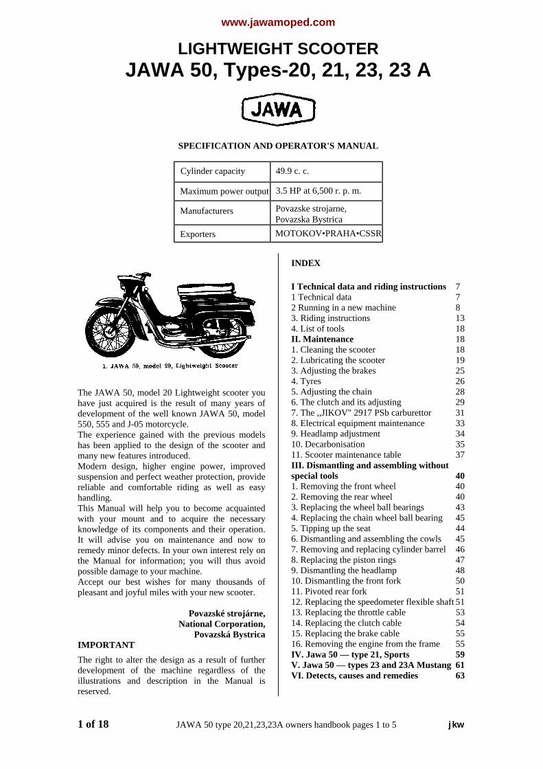
The JAWA 50, model 20 Lightweight scooter youhave just acquired is the result of many years ofdevelopment of the well known JAWA 50, model550, 555 and J-05 motorcycle.The experience gained with the previous modelshas been applied to the design of the scooter andmany new features introduced.Modern design, higher engine power, improvedsuspension and perfect weather protection, providereliable and comfortable riding as well as easyhandling.This Manual will help you to become acquaintedwith your mount and to acquire the necessaryknowledge of its components and their operation.It will advise you on maintenance and now toremedy minor defects. In your own interest rely onthe Manual for information; you will thus avoidpossible damage to your machine.Accept our best wishes for many thousands ofpleasant and joyful miles with your new scooter.
Povazské strojárne,National Corporation,
Povazská BystricaIMPORTANTThe right to alter the design as a result of furtherdevelopment of the machine regardless of theillustrations and description in the Manual isreserved.
INDEX
I Technical data and riding instructions 71 Technical data 72 Running in a new machine 83. Riding instructions 134. List of tools 18II. Maintenance 181. Cleaning the scooter 182. Lubricating the scooter 193. Adjusting the brakes 254. Tyres 265. Adjusting the chain 286. The clutch and its adjusting 297. The ,,JIKOV" 2917 PSb carburettor 318. Electrical equipment maintenance 339. Headlamp adjustment 3410. Decarbonisation 3511. Scooter maintenance table 37III. Dismantling and assembling withoutspecial tools 401. Removing the front wheel 402. Removing the rear wheel 403. Replacing the wheel ball bearings 434. Replacing the chain wheel ball bearing 455. Tipping up the seat 446. Dismantling and assembling the cowls 457. Removing and replacing cylinder barrel 468. Replacing the piston rings 479. Dismantling the headlamp 4810. Dismantling the front fork 5011. Pivoted rear fork 5112. Replacing the speedometer flexible shaft 5113. Replacing the throttle cable 5314. Replacing the clutch cable 5415. Replacing the brake cable 5516. Removing the engine from the frame 55IV. Jawa 50 — type 21, Sports 59V. Jawa 50 — types 23 and 23A Mustang 61VI. Detects, causes and remedies 63
1 of 18 JAWA 50 type 20,21,23,23A owners handbook pages 1 to 5 jkw

www.jawamoped.com
I. TECHNICAL DATA AND RIDINGINSTRUCTION
TECHNICAL DATAEngine — two-stroke, air-cooledNumber of cylinders — singleBore — 38 mmStroke — 44 mmCylinder capacity — 49.9 c. c.Compression ratio — 9,2 to 1Maximum power output — 3.5 HP at 6,500 r p m.
[2.65 HP at 6,500 r.p.m}Fuel tank capacity — 1.2 galls. (5.5 litres)Weight - dry - 143 lbs. ± 2% (65 kg ± 2%)Payload - 352 lbs. (160 kg)Primary drive - by CZ-Favorit chain 3/8 x 3/8 in., 44 links (CSN 023321.1) .Final drive - by chain 12.7 x 5.2; 111 links [by chain 12.7 x 5.2; 111+1 links with ratio 11/55 teeth]Overall gear rations I. II. Bottom gear 27.72 to 1 30.03 to 1 Second gear 15.18 to 1 16.44 to 1 Top gear 10.27 to 1 11.13 to 1Carburettor — Jikov 2917 PSbWheels — front and rear interchangeable rims - 1.50 A x 16 in. tyres - 2.75 x 16 in.Internal expanding brakes — dia. 125/20 mmFront wheel suspension — telescopic fork, suspension travel 90 mm ;Rear wheel suspension — pivoted rear fork with dampers, suspension travel 85 mmMagneto — 6V with windings for feeding the ignition coil, the headlamp bulb 15/15 W, and the identity end plate bulb 5 W
[headlamp bulb 25/25w + stop light bulb 10w][Battery - YANASA 6N4-2A-4 with fuse, stop switch BURGESS]Ignition coil — 8 V, 02-9210.30Sparking plug — PAL 14-8R with suppressorAverage fuel consumption — 0.5 galls / 60 miles 2.3 lt. / 100 km.Maximum speed - 37 mph. (60 kph.) [30 mph +5mph]Maximum climbing ability — 25%
[Supplement for JAWA 50 type 223.220 in italics]
2 of 18 JAWA 50 type 20, 21, 23, 23A Owners Handbook page 6 to 8/9 jkw
www.jawamoped.com
2. RUNNING IN A NEW MACHINE
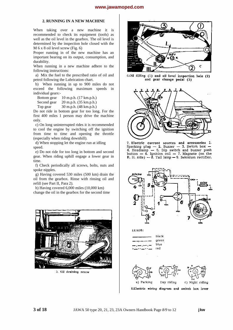
When taking over a new machine it isrecommended to check its equipment (tools) aswell as the oil level in the gearbox. The oil level isdetermined by the inspection hole closed with theM 6 x 8 oil level screw (Fig. 6)Proper running in of the new machine has animportant bearing on its output, consumption, anddurability.When running in a new machine adhere to thefollowing instructions: a) Mix the fuel to the prescribed ratio of oil andpetrol following the Lubrication chart. b) When running in up to 900 miles do notexceed the following maximum speeds inindividual gears:- Bottom gear 10 m.p.h. (17 km.p.h.) Second gear 20 m.p.h. (35 km.p.h.) Top gear 30 m.p.h. (48 km.p.h.)Do not ride in bottom gear for too long. For thefirst 400 miles 1 person may drive the machineonly. c) On long uninterrupted rides it is recommendedto cool the engine by switching off the ignitionfrom time to time and opening the throttle(especially when riding downhill). d) When stopping let the engine run at idlingspeed. e) Do not ride for too long in bottom and secondgear. When riding uphill engage a lower gear intime. f) Check periodically all screws, bolts, nuts andspoke nipples. g) Having covered 530 miles (500 km) drain theoil from the gearbox. Rinse with rinsing oil andrefill (see Part II, Para 2). h) Having covered 6,000 miles (10,000 km)change the oil in the gearbox for the second time
3 of 18 JAWA 50 type 20, 21, 23, 23A Owners Handbook Page 8/9 to 12 jkw
www.jawamoped.com
3. RIDING INSTRUCTIONS
A. Check before a ride:
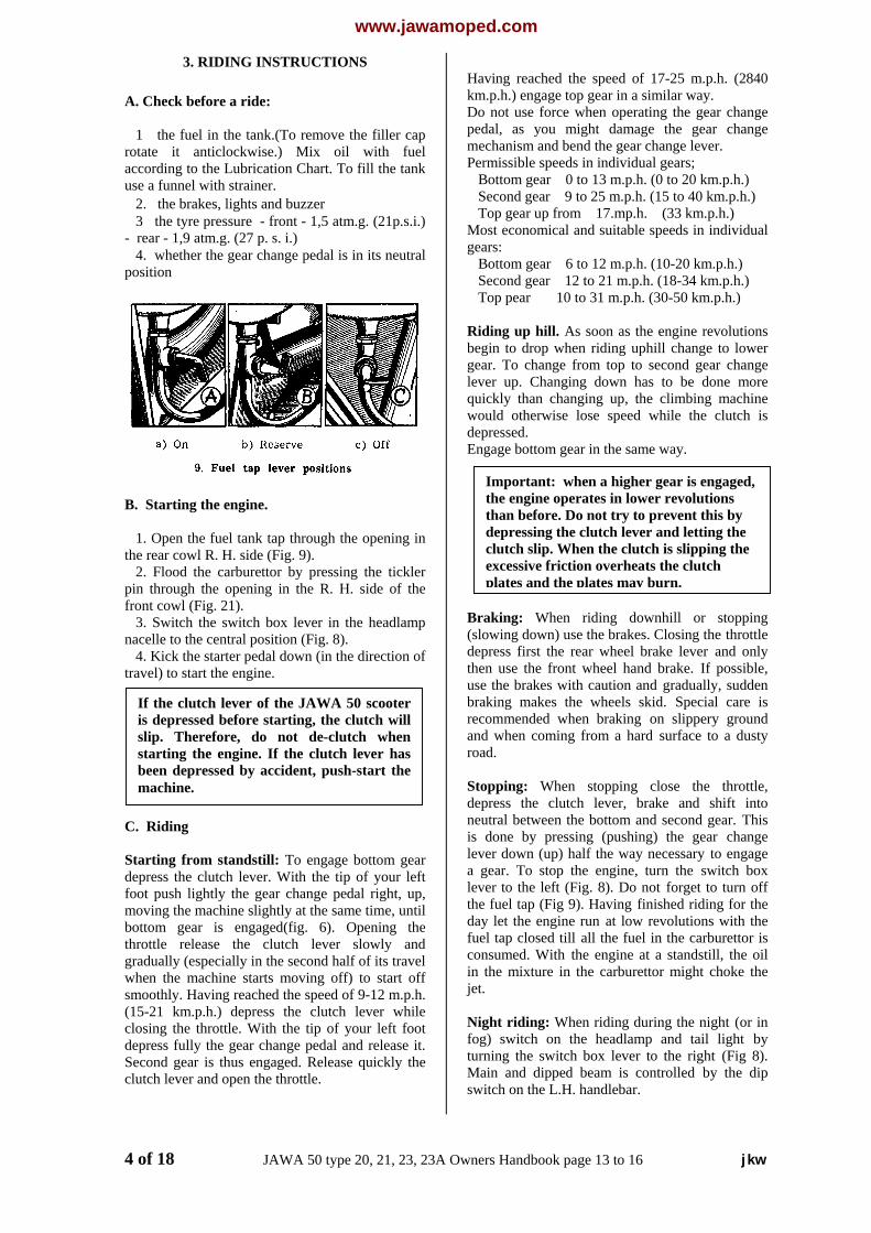
1 the fuel in the tank.(To remove the filler caprotate it anticlockwise.) Mix oil with fuelaccording to the Lubrication Chart. To fill the tankuse a funnel with strainer. 2. the brakes, lights and buzzer 3 the tyre pressure - front - 1,5 atm.g. (21p.s.i.)- rear - 1,9 atm.g. (27 p. s. i.) 4. whether the gear change pedal is in its neutralposition
B. Starting the engine.
1. Open the fuel tank tap through the opening inthe rear cowl R. H. side (Fig. 9). 2. Flood the carburettor by pressing the ticklerpin through the opening in the R. H. side of thefront cowl (Fig. 21). 3. Switch the switch box lever in the headlampnacelle to the central position (Fig. 8). 4. Kick the starter pedal down (in the direction oftravel) to start the engine.
C. Riding
Starting from standstill: To engage bottom geardepress the clutch lever. With the tip of your leftfoot push lightly the gear change pedal right, up,moving the machine slightly at the same time, untilbottom gear is engaged(fig. 6). Opening thethrottle release the clutch lever slowly andgradually (especially in the second half of its travelwhen the machine starts moving off) to start offsmoothly. Having reached the speed of 9-12 m.p.h.(15-21 km.p.h.) depress the clutch lever whileclosing the throttle. With the tip of your left footdepress fully the gear change pedal and release it.Second gear is thus engaged. Release quickly theclutch lever and open the throttle.
Having reached the speed of 17-25 m.p.h. (2840km.p.h.) engage top gear in a similar way.Do not use force when operating the gear changepedal, as you might damage the gear changemechanism and bend the gear change lever.Permissible speeds in individual gears; Bottom gear 0 to 13 m.p.h. (0 to 20 km.p.h.) Second gear 9 to 25 m.p.h. (15 to 40 km.p.h.) Top gear up from 17.mp.h. (33 km.p.h.)Most economical and suitable speeds in individualgears: Bottom gear 6 to 12 m.p.h. (10-20 km.p.h.) Second gear 12 to 21 m.p.h. (18-34 km.p.h.) Top pear 10 to 31 m.p.h. (30-50 km.p.h.)
Riding up hill. As soon as the engine revolutionsbegin to drop when riding uphill change to lowergear. To change from top to second gear changelever up. Changing down has to be done morequickly than changing up, the climbing machinewould otherwise lose speed while the clutch isdepressed.Engage bottom gear in the same way.
B(sdethusbrreanro
Stdeneislea lethdafucoinje
NfotuMsw
4 of 18 JAWA 50 type 20, 21, 23, 23A Own
If the clutch lever of the JAWA 50 scooteris depressed before starting, the clutch willslip. Therefore, do not de-clutch whenstarting the engine. If the clutch lever hasbeen depressed by accident, push-start themachine.
Important: when a higher gear is engaged,the engine operates in lower revolutionsthan before. Do not try to prevent this bydepressing the clutch lever and letting theclutch slip. When the clutch is slipping theexcessive friction overheats the clutchplates and the plates may burn.
raking: When riding downhill or stoppinglowing down) use the brakes. Closing the throttlepress first the rear wheel brake lever and onlyen use the front wheel hand brake. If possible,e the brakes with caution and gradually, suddenaking makes the wheels skid. Special care iscommended when braking on slippery groundd when coming from a hard surface to a dustyad.
opping: When stopping close the throttle,press the clutch lever, brake and shift intoutral between the bottom and second gear. This
done by pressing (pushing) the gear changever down (up) half the way necessary to engagegear. To stop the engine, turn the switch boxver to the left (Fig. 8). Do not forget to turn offe fuel tap (Fig 9). Having finished riding for they let the engine run at low revolutions with theel tap closed till all the fuel in the carburettor isnsumed. With the engine at a standstill, the oil the mixture in the carburettor might choke thet.
ight riding: When riding during the night (or ing) switch on the headlamp and tail light byrning the switch box lever to the right (Fig 8).ain and dipped beam is controlled by the dipitch on the L.H. handlebar.
ers Handbook page 13 to 16 jkw
www.jawamoped.com
D. How to prevent defects
If the instructions for running in and furthermaintenance are not followed defects may occur.The most frequent consequence of incorrectrunning in is sticking of the piston rings in theirgrooves, the result of which is a lowered engineoutput, or even a seized piston.Incorrect running in often does not manifest itselfin a visible detect, but in premature wear ofdifferent parts and a considerable increase in fuelconsumption.Seizing of the piston is mostly caused, by engineoverheating, which is usually accompanied by acharacteristic slight pinking. As soon as you hearthis sound switch the ignition off so that the freshun-ignited mixture can cool off the engine.If the engine starts losing power it is also due toseizing; it is necessary to declutch and stop. If thepiston has seized, let the engine cool off and thentry to restart it. On your return check the piston,piston rings and the cylinder inside. Should arepair be necessary, entrust it to a specialisedworkshop.It is harmful to let the engine run while it isstanding as it is not being cooled. Do not keep itdeclutched for any considerable time as the corkinserts of the clutch plates would be subject tounnecessary wear. Never help the engine uphill byletting the clutch ,,slip", but engage a lower gear intime. Do not ride in lower gears for too long.
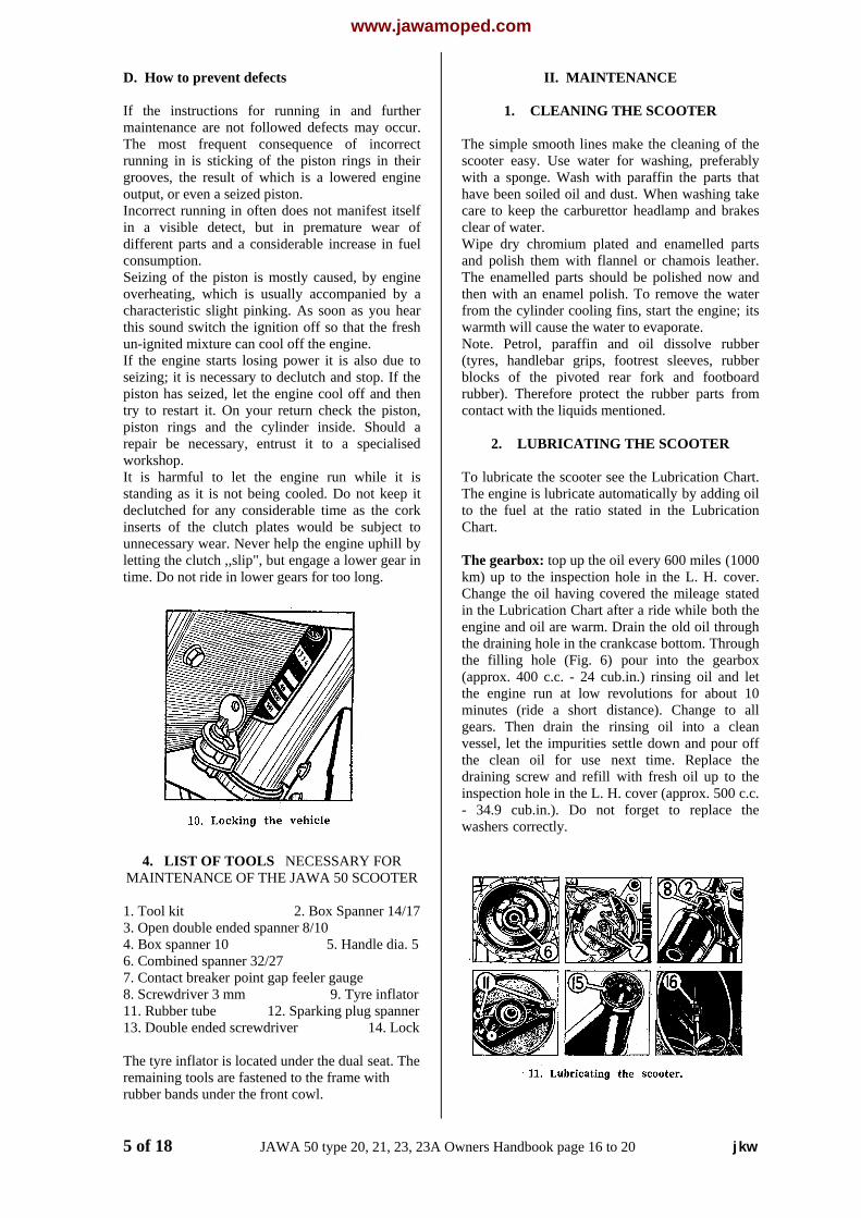
4. LIST OF TOOLS NECESSARY FORMAINTENANCE OF THE JAWA 50 SCOOTER
1. Tool kit 2. Box Spanner 14/173. Open double ended spanner 8/104. Box spanner 10 5. Handle dia. 56. Combined spanner 32/277. Contact breaker point gap feeler gauge8. Screwdriver 3 mm 9. Tyre inflator11. Rubber tube 12. Sparking plug spanner13. Double ended screwdriver 14. Lock
The tyre inflator is located under the dual seat. Theremaining tools are fastened to the frame withrubber bands under the front cowl.
II. MAINTENANCE
1. CLEANING THE SCOOTER
The simple smooth lines make the cleaning of thescooter easy. Use water for washing, preferablywith a sponge. Wash with paraffin the parts thathave been soiled oil and dust. When washing takecare to keep the carburettor headlamp and brakesclear of water.Wipe dry chromium plated and enamelled partsand polish them with flannel or chamois leather.The enamelled parts should be polished now andthen with an enamel polish. To remove the waterfrom the cylinder cooling fins, start the engine; itswarmth will cause the water to evaporate.Note. Petrol, paraffin and oil dissolve rubber(tyres, handlebar grips, footrest sleeves, rubberblocks of the pivoted rear fork and footboardrubber). Therefore protect the rubber parts fromcontact with the liquids mentioned.
2. LUBRICATING THE SCOOTER
To lubricate the scooter see the Lubrication Chart.The engine is lubricate automatically by adding oilto the fuel at the ratio stated in the LubricationChart.
The gearbox: top up the oil every 600 miles (1000km) up to the inspection hole in the L. H. cover.Change the oil having covered the mileage statedin the Lubrication Chart after a ride while both theengine and oil are warm. Drain the old oil throughthe draining hole in the crankcase bottom. Throughthe filling hole (Fig. 6) pour into the gearbox(approx. 400 c.c. - 24 cub.in.) rinsing oil and letthe engine run at low revolutions for about 10minutes (ride a short distance). Change to allgears. Then drain the rinsing oil into a cleanvessel, let the impurities settle down and pour offthe clean oil for use next time. Replace thedraining screw and refill with fresh oil up to theinspection hole in the L. H. cover (approx. 500 c.c.- 34.9 cub.in.). Do not forget to replace thewashers correctly.
5 of 18 JAWA 50 type 20, 21, 23, 23A Owners Handbook page 16 to 20 jkw
www.jawamoped.com
The clutch: runs in an oil bath (oil from thegearbox).
Telescopic front fork: lubricate, after every 600miles (1000 km); put the oil diluted grease into thefork legs by means of grease nipple after screwingoff two screws M6 x 7 at the back part oftelescopic fork (behind the headlamp). Havingcovered 3,100 miles (5000 km) dismantle the forkand lubricate carefully with grease.
Wheels (bearings) have to be lubricated every1,500 miles (2500 km). Dismantle the wheels (seePart III, Para 3-4), wash the bearings in benzine,dry and fill them with grease. Fill up with greasethe space of sealing rings at the shaftapproximately to one third to avoid the penetratingof impurities and moisture. Do not overfill thewheel hubs!
The pivoted rear fork telescopic oil dampers arehighly efficient and are so arranged that there is noneed to top up the damper liquid. Top up thedamper liquid only it the pivoted rear fork isoscillating freely or bottoming or if the liquid isleaking. Otherwise change the oil once in twoyears. Entrust the topping up or the change ofliquid to a specialised workshop.
The primary chain is completely enclosed by theL. H. crankcase cover, runs in an oil bath and doesnot require any maintenance. If worn or stretchedtoo much it has to be replaced. If the primary chainhas to be replaced, it is necessary to dismantle alsothe clutch. It is recommended to entrust this repairto a specialised workshop equipped with thenecessary tools.
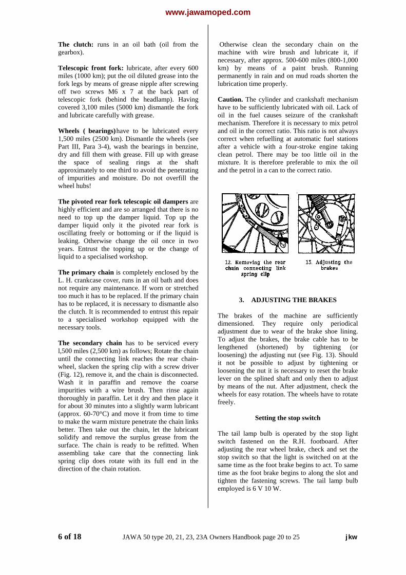
The secondary chain has to be serviced everyl,500 miles (2,500 km) as follows; Rotate the chainuntil the connecting link reaches the rear chain-wheel, slacken the spring clip with a screw driver(Fig. 12), remove it, and the chain is disconnected.Wash it in paraffin and remove the coarseimpurities with a wire brush. Then rinse againthoroughly in paraffin. Let it dry and then place itfor about 30 minutes into a slightly warm lubricant(approx. 60-70°C) and move it from time to timeto make the warm mixture penetrate the chain linksbetter. Then take out the chain, let the lubricantsolidify and remove the surplus grease from thesurface. The chain is ready to be refitted. Whenassembling take care that the connecting linkspring clip does rotate with its full end in thedirection of the chain rotation.
Otherwise clean the secondary chain on themachine with wire brush and lubricate it, ifnecessary, after approx. 500-600 miles (800-1,000km) by means of a paint brush. Runningpermanently in rain and on mud roads shorten thelubrication time properly.
Caution. The cylinder and crankshaft mechanismhave to be sufficiently lubricated with oil. Lack ofoil in the fuel causes seizure of the crankshaftmechanism. Therefore it is necessary to mix petroland oil in the correct ratio. This ratio is not alwayscorrect when refuelling at automatic fuel stationsafter a vehicle with a four-stroke engine takingclean petrol. There may be too little oil in themixture. It is therefore preferable to mix the oiland the petrol in a can to the correct ratio.
3. ADJUSTING THE BRAKES
The brakes of the machine are sufficientlydimensioned. They require only periodicaladjustment due to wear of the brake shoe lining.To adjust the brakes, the brake cable has to belengthened (shortened) by tightening (orloosening) the adjusting nut (see Fig. 13). Shouldit not be possible to adjust by tightening orloosening the nut it is necessary to reset the brakelever on the splined shaft and only then to adjustby means of the nut. After adjustment, check thewheels for easy rotation. The wheels have to rotatefreely.
Setting the stop switch
The tail lamp bulb is operated by the stop lightswitch fastened on the R.H. footboard. Afteradjusting the rear wheel brake, check and set thestop switch so that the light is switched on at thesame time as the foot brake begins to act. To sametime as the foot brake begins to along the slot andtighten the fastening screws. The tail lamp bulbemployed is 6 V 10 W.
6 of 18 JAWA 50 type 20, 21, 23, 23A Owners Handbook page 20 to 25 jkw
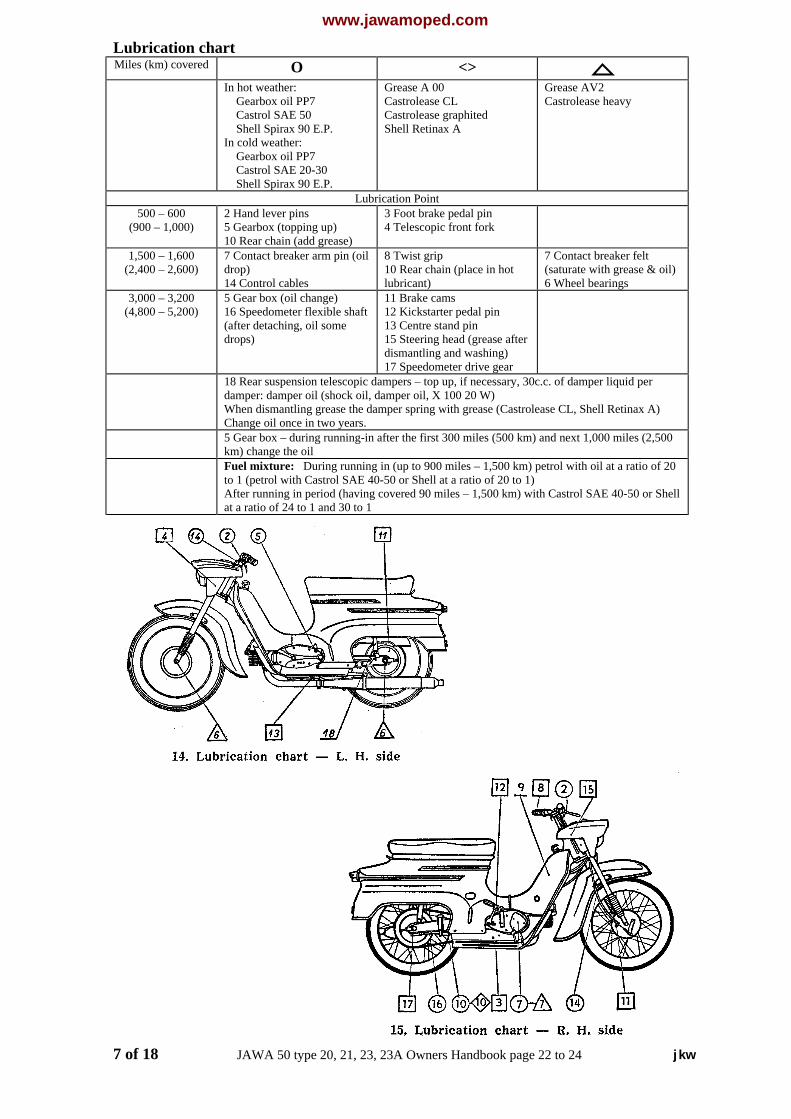
www.jawamoped.comLubrication chartMiles (km) covered O � <>
In hot weather: Gearbox oil PP7 Castrol SAE 50 Shell Spirax 90 E.P.In cold weather: Gearbox oil PP7 Castrol SAE 20-30 Shell Spirax 90 E.P.
Grease A 00Castrolease CLCastrolease graphitedShell Retinax A
Grease AV2Castrolease heavy
Lubrication Point500 – 600
(900 – 1,000)2 Hand lever pins5 Gearbox (topping up)10 Rear chain (add grease)
3 Foot brake pedal pin4 Telescopic front fork
1,500 – 1,600(2,400 – 2,600)
7 Contact breaker arm pin (oildrop)14 Control cables
8 Twist grip10 Rear chain (place in hotlubricant)
7 Contact breaker felt(saturate with grease & oil)6 Wheel bearings
3,000 – 3,200(4,800 – 5,200)
5 Gear box (oil change)16 Speedometer flexible shaft(after detaching, oil somedrops)
11 Brake cams12 Kickstarter pedal pin13 Centre stand pin15 Steering head (grease afterdismantling and washing)17 Speedometer drive gear
18 Rear suspension telescopic dampers – top up, if necessary, 30c.c. of damper liquid perdamper: damper oil (shock oil, damper oil, X 100 20 W)When dismantling grease the damper spring with grease (Castrolease CL, Shell Retinax A)Change oil once in two years.5 Gear box – during running-in after the first 300 miles (500 km) and next 1,000 miles (2,500km) change the oilFuel mixture: During running in (up to 900 miles – 1,500 km) petrol with oil at a ratio of 20to 1 (petrol with Castrol SAE 40-50 or Shell at a ratio of 20 to 1)After running in period (having covered 90 miles – 1,500 km) with Castrol SAE 40-50 or Shellat a ratio of 24 to 1 and 30 to 1
7 of 18 JAWA 50 type 20, 21, 23, 23A Owners Handbook page 22 to 24 jkw
www.jawamoped.com
4. TYRES
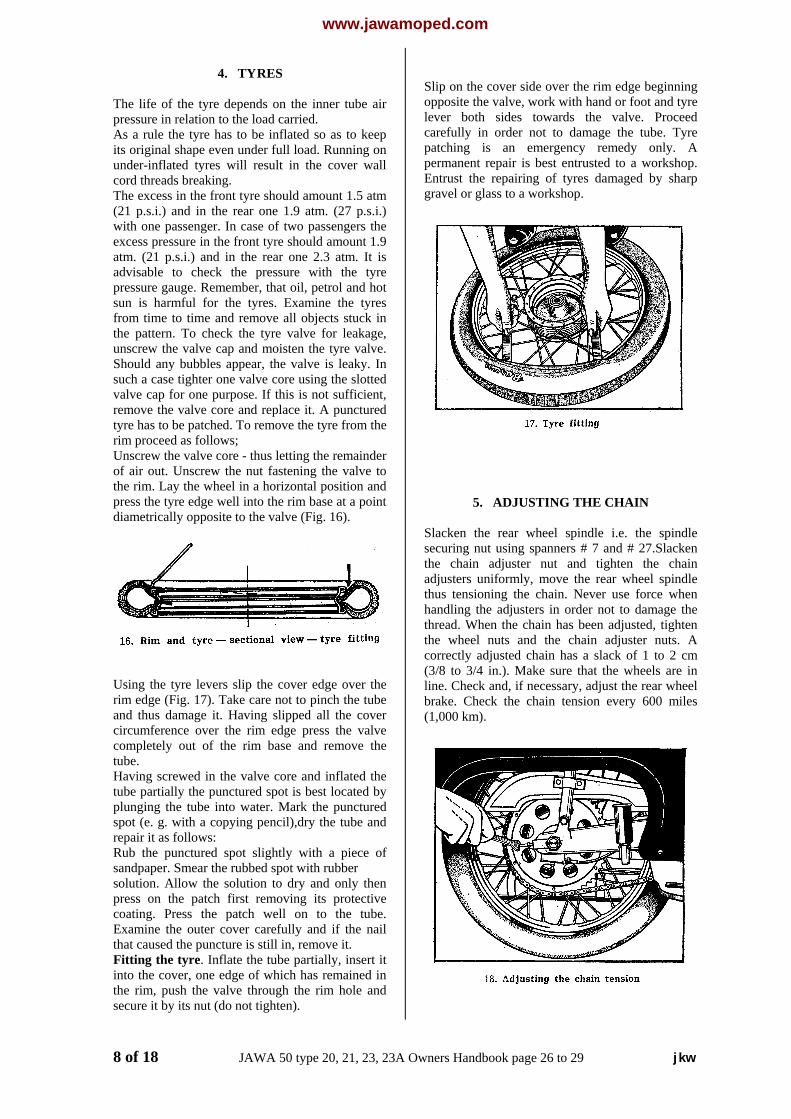
The life of the tyre depends on the inner tube airpressure in relation to the load carried.As a rule the tyre has to be inflated so as to keepits original shape even under full load. Running onunder-inflated tyres will result in the cover wallcord threads breaking.The excess in the front tyre should amount 1.5 atm(21 p.s.i.) and in the rear one 1.9 atm. (27 p.s.i.)with one passenger. In case of two passengers theexcess pressure in the front tyre should amount 1.9atm. (21 p.s.i.) and in the rear one 2.3 atm. It isadvisable to check the pressure with the tyrepressure gauge. Remember, that oil, petrol and hotsun is harmful for the tyres. Examine the tyresfrom time to time and remove all objects stuck inthe pattern. To check the tyre valve for leakage,unscrew the valve cap and moisten the tyre valve.Should any bubbles appear, the valve is leaky. Insuch a case tighter one valve core using the slottedvalve cap for one purpose. If this is not sufficient,remove the valve core and replace it. A puncturedtyre has to be patched. To remove the tyre from therim proceed as follows;Unscrew the valve core - thus letting the remainderof air out. Unscrew the nut fastening the valve tothe rim. Lay the wheel in a horizontal position andpress the tyre edge well into the rim base at a pointdiametrically opposite to the valve (Fig. 16).
Using the tyre levers slip the cover edge over therim edge (Fig. 17). Take care not to pinch the tubeand thus damage it. Having slipped all the covercircumference over the rim edge press the valvecompletely out of the rim base and remove thetube.Having screwed in the valve core and inflated thetube partially the punctured spot is best located byplunging the tube into water. Mark the puncturedspot (e. g. with a copying pencil),dry the tube andrepair it as follows:Rub the punctured spot slightly with a piece ofsandpaper. Smear the rubbed spot with rubbersolution. Allow the solution to dry and only thenpress on the patch first removing its protectivecoating. Press the patch well on to the tube.Examine the outer cover carefully and if the nailthat caused the puncture is still in, remove it.Fitting the tyre. Inflate the tube partially, insert itinto the cover, one edge of which has remained inthe rim, push the valve through the rim hole andsecure it by its nut (do not tighten).
Slip on the cover side over the rim edge beginningopposite the valve, work with hand or foot and tyrelever both sides towards the valve. Proceedcarefully in order not to damage the tube. Tyrepatching is an emergency remedy only. Apermanent repair is best entrusted to a workshop.Entrust the repairing of tyres damaged by sharpgravel or glass to a workshop.
5. ADJUSTING THE CHAIN
Slacken the rear wheel spindle i.e. the spindlesecuring nut using spanners # 7 and # 27.Slackenthe chain adjuster nut and tighten the chainadjusters uniformly, move the rear wheel spindlethus tensioning the chain. Never use force whenhandling the adjusters in order not to damage thethread. When the chain has been adjusted, tightenthe wheel nuts and the chain adjuster nuts. Acorrectly adjusted chain has a slack of 1 to 2 cm(3/8 to 3/4 in.). Make sure that the wheels are inline. Check and, if necessary, adjust the rear wheelbrake. Check the chain tension every 600 miles(1,000 km).
8 of 18 JAWA 50 type 20, 21, 23, 23A Owners Handbook page 26 to 29 jkw
www.jawamoped.com
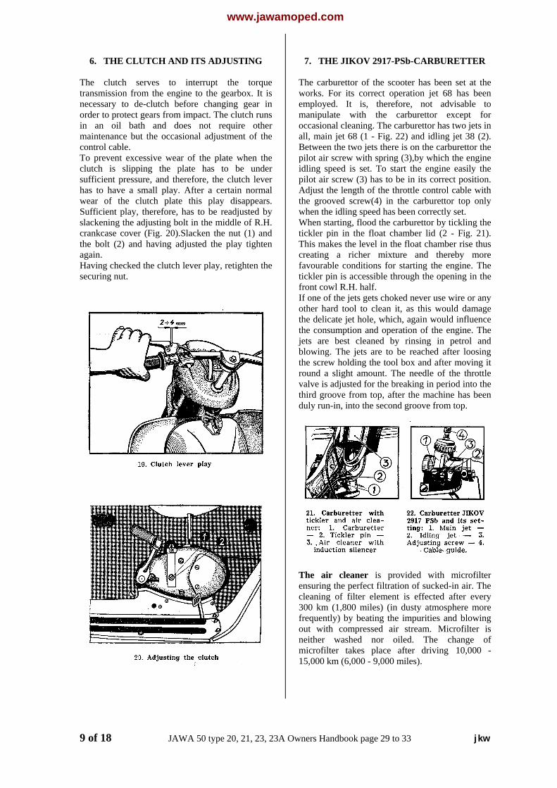
6. THE CLUTCH AND ITS ADJUSTING
The clutch serves to interrupt the torquetransmission from the engine to the gearbox. It isnecessary to de-clutch before changing gear inorder to protect gears from impact. The clutch runsin an oil bath and does not require othermaintenance but the occasional adjustment of thecontrol cable.To prevent excessive wear of the plate when theclutch is slipping the plate has to be undersufficient pressure, and therefore, the clutch leverhas to have a small play. After a certain normalwear of the clutch plate this play disappears.Sufficient play, therefore, has to be readjusted byslackening the adjusting bolt in the middle of R.H.crankcase cover (Fig. 20).Slacken the nut (1) andthe bolt (2) and having adjusted the play tightenagain.Having checked the clutch lever play, retighten thesecuring nut.
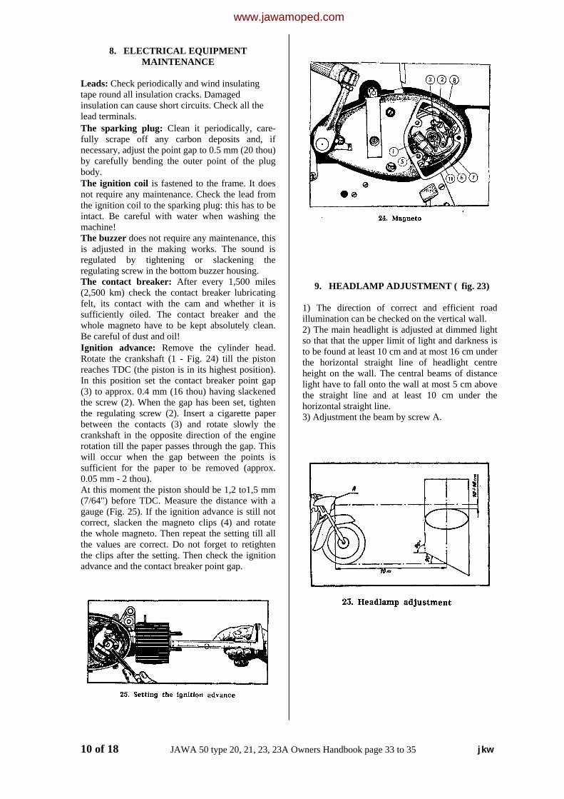
7. THE JIKOV 2917-PSb-CARBURETTER
The carburettor of the scooter has been set at theworks. For its correct operation jet 68 has beenemployed. It is, therefore, not advisable tomanipulate with the carburettor except foroccasional cleaning. The carburettor has two jets inall, main jet 68 (1 - Fig. 22) and idling jet 38 (2).Between the two jets there is on the carburettor thepilot air screw with spring (3),by which the engineidling speed is set. To start the engine easily thepilot air screw (3) has to be in its correct position.Adjust the length of the throttle control cable withthe grooved screw(4) in the carburettor top onlywhen the idling speed has been correctly set.When starting, flood the carburettor by tickling thetickler pin in the float chamber lid (2 - Fig. 21).This makes the level in the float chamber rise thuscreating a richer mixture and thereby morefavourable conditions for starting the engine. Thetickler pin is accessible through the opening in thefront cowl R.H. half.If one of the jets gets choked never use wire or anyother hard tool to clean it, as this would damagethe delicate jet hole, which, again would influencethe consumption and operation of the engine. Thejets are best cleaned by rinsing in petrol andblowing. The jets are to be reached after loosingthe screw holding the tool box and after moving itround a slight amount. The needle of the throttlevalve is adjusted for the breaking in period into thethird groove from top, after the machine has beenduly run-in, into the second groove from top.
The air cleaner is provided with microfilterensuring the perfect filtration of sucked-in air. Thecleaning of filter element is effected after every300 km (1,800 miles) (in dusty atmosphere morefrequently) by beating the impurities and blowingout with compressed air stream. Microfilter isneither washed nor oiled. The change ofmicrofilter takes place after driving 10,000 -15,000 km (6,000 - 9,000 miles).
9 of 18 JAWA 50 type 20, 21, 23, 23A Owners Handbook page 29 to 33 jkw
www.jawamoped.com
8. ELECTRICAL EQUIPMENTMAINTENANCE
Leads: Check periodically and wind insulatingtape round all insulation cracks. Damagedinsulation can cause short circuits. Check all thelead terminals.The sparking plug: Clean it periodically, care-fully scrape off any carbon deposits and, ifnecessary, adjust the point gap to 0.5 mm (20 thou)by carefully bending the outer point of the plugbody.The ignition coil is fastened to the frame. It doesnot require any maintenance. Check the lead fromthe ignition coil to the sparking plug: this has to beintact. Be careful with water when washing themachine!The buzzer does not require any maintenance, thisis adjusted in the making works. The sound isregulated by tightening or slackening theregulating screw in the bottom buzzer housing.The contact breaker: After every 1,500 miles(2,500 km) check the contact breaker lubricatingfelt, its contact with the cam and whether it issufficiently oiled. The contact breaker and thewhole magneto have to be kept absolutely clean.Be careful of dust and oil!Ignition advance: Remove the cylinder head.Rotate the crankshaft (1 - Fig. 24) till the pistonreaches TDC (the piston is in its highest position).In this position set the contact breaker point gap(3) to approx. 0.4 mm (16 thou) having slackenedthe screw (2). When the gap has been set, tightenthe regulating screw (2). Insert a cigarette paperbetween the contacts (3) and rotate slowly thecrankshaft in the opposite direction of the enginerotation till the paper passes through the gap. Thiswill occur when the gap between the points issufficient for the paper to be removed (approx.0.05 mm - 2 thou).At this moment the piston should be 1,2 to1,5 mm(7/64") before TDC. Measure the distance with agauge (Fig. 25). If the ignition advance is still notcorrect, slacken the magneto clips (4) and rotatethe whole magneto. Then repeat the setting till allthe values are correct. Do not forget to retightenthe clips after the setting. Then check the ignitionadvance and the contact breaker point gap.
9. HEADLAMP ADJUSTMENT (fig. 23)
1) The direction of correct and efficient roadillumination can be checked on the vertical wall.2) The main headlight is adjusted at dimmed lightso that that the upper limit of light and darkness isto be found at least 10 cm and at most 16 cm underthe horizontal straight line of headlight centreheight on the wall. The central beams of distancelight have to fall onto the wall at most 5 cm abovethe straight line and at least 10 cm under thehorizontal straight line.3) Adjustment the beam by screw A.
10 of 18 JAWA 50 type 20, 21, 23, 23A Owners Handbook page 33 to 35 jkw
www.jawamoped.com
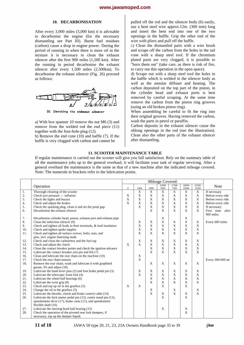
10. DECARBONISATION
After every 3,000 miles (5,000 km) it is advisableto decarbonise the engine (for the necessarydismantling see Part III). Burnt fuel residues(carbon) cause a drop in engine power. During theperiod of running in when there is more oil in themixture it is necessary to clean the exhaustsilencer after the first 900 miles (1,500 km). Afterthe running in period decarbonise the exhaustsilencer after every 1,500 miles (2,500km). Todecarbonise the exhaust silencer (Fig. 26) proceedas follows:
a) With box spanner 10 remove the nut M6 (3) andremove from the welded rod the end piece (11)together with the four-hole-plug (12).b) Remove the end cone (10) and baffle (7). If thebaffle is very clogged with carbon and cannot be
pulled off the rod and the silencer body (6) easily,use a bent steel wire approx.12in. (300 mm) longand insert the bent end into one of the twoopenings in the baffle. Grip the other end of thewire with pliers and pull off the baffle.c) Clean the dismantled parts with a wire brushand scrape off the carbon from the holes in the tailcone with a sharp steel tool. If the chromiumplated parts are very clogged, it is possible to"burn them out" (take care, as there is risk of fire,to carry out this operation in the open space).d) Scrape out with a sharp steel tool the holes inthe baffle which is welded in the silencer body aswell as the annular diffuser and heating. Thecarbon deposited on the top part of the piston, inthe cylinder head and exhaust ports is bestremoved by careful scraping. At the same timeremove the carbon from the piston ring grooves(using an old broken piston ring).When assembling be careful to fit the ring intotheir original grooves. Having removed the carbon,wash the parts in petrol or paraffin.Carbon deposits in the exhaust silencer cause theoblong openings in the rod (see the illustration).Clean also the other parts of the exhaust silencerafter dismantling.
11. SCOOTER MAINTENANCE TABLEIf regular maintenance is carried out the scooter will give you full satisfaction. Rely on the summary table ofall the maintenance jobs up to the general overhaul; it will facilitate your task of regular servicing. After ageneral overhaul the maintenance is the same as that of a new machine after the indicated mileage covered.Note: The numerals in brackets refer to the lubrication points.
Mileage Covered:Operation 0 1000 3000
150005000
175007500
2000010000
2250012500 Note
1.2.3.4.5.6.
7.8.9.10.11.
12.13.14.15.16.17.18.
19.20.21.22.23.24.25.26.
27.28.
Thorough cleaning of the scooterCheck tyre pressure — inflationCheck the lights and buzzerCheck and adjust the brakesCheck the sparking plug, clean it and set the point gapDecarbonise the exhaust silencer
Decarbonise cylinder head, piston, exhaust port and exhaust pipeClean the induction silencer (9)Check and tighten all leads in their terminals, & lead insulationCheck and tighten spoke nipplesCheck and tighten all surface screws, bolts, nuts, andpins, incl. engine fastening studsCheck and clean the carburettor and the fuel tapCheck and adjust the clutchClean the contact breaker points and check the ignition advanceLubricate the contact breaker arm pin and felt (7)Clean and lubricate the rear chain on the machine (10)Check the rear chain tensionRemove the rear chain, wash and lubricate it with graphitedgrease. Fit and adjust (10)Lubricate the hand lever pins (2) and foot brake pedal pin (3)Lubricate the telescopic front fork (4)Lubricate the wheel ball bearings (6)Lubricate the twist grip (8)Check and top up oil in the gearbox (5)Change the oil in the gearbox (5)Lubricate the throttle, clutch and brake control cable (14)Lubricate the kick starter pedal pin (12), centre stand pin (13),speedometer drive (17), brake cams (11), and speedometerflexible shaft (16)Lubricate the steering head ball bearing (15)Check the operation of the pivoted rear fork dampers, ifnecessary, top up the damper liquid.
XXX
X
X
XXXXX
XXXX
XX
XX
XX
X
XXXXXX
XXXX
XXXX
X
XXXX
XX
XXXXXX
XXXXX
XXXX
X
XXXXX
XX
X
XXXXXX
XXXX
XXXX
X
XXXX
XX
XXXXXX
XXXXX
XXXX
X
XXXXX
XX
XX
XXXXXX
XXXX
XXXX
X
XXXX
XX
If necessaryBefore every rideBefore every rideBefore every rideIf necessaryFirst time after900 miles
Every 600 miles
Every 500-600 mi
11 of 18 JAWA 50 type 20, 21, 23, 23A Owners Handbook page 35 to 39 jkw
www.jawamoped.com
III. DISMANTLING AND ASSEMBLINGWITHOUT SPECIAL TOOLS
1. REMOVING THE FRONT WHEEL
To remove: a) Unscrew the bowden cable nut and take thebowden cable off the brake cams lever. b) Unscrew the wheel spindle nut remove thespring washer and wheel spindle. c) Turn the R. H. front fork leg slider and removethe brake torque reaction anchor on the back platefrom the opening in the fork leg and take the wheeloff.To replace: A. Check the position of the brake cable rest onthe handlebars. B. Replace the wheel and turning the R. H. forkleg slider push the brake torque reaction anchorhome on the back plate into the opening in theslider. C. Replace the front wheel spindle from the left. D. Replace the spring washer and screw the nuton from the right. E. After replacing the cowl and the wheel on themachine push the bowden cable of the rear brakeand the cowl rest. Push the bowden cable screw onthe brake lever and adjust the brakes.
2. REMOVING THE REAR WHEEL
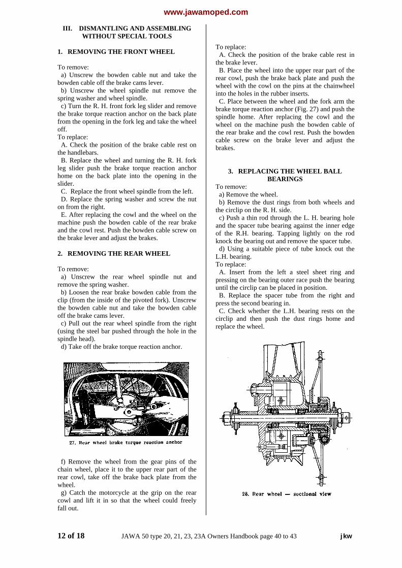
To remove: a) Unscrew the rear wheel spindle nut andremove the spring washer. b) Loosen the rear brake bowden cable from theclip (from the inside of the pivoted fork). Unscrewthe bowden cable nut and take the bowden cableoff the brake cams lever. c) Pull out the rear wheel spindle from the right(using the steel bar pushed through the hole in thespindle head). d) Take off the brake torque reaction anchor.
f) Remove the wheel from the gear pins of thechain wheel, place it to the upper rear part of therear cowl, take off the brake back plate from thewheel. g) Catch the motorcycle at the grip on the rearcowl and lift it in so that the wheel could freelyfall out.
To replace: A. Check the position of the brake cable rest inthe brake lever. B. Place the wheel into the upper rear part of therear cowl, push the brake back plate and push thewheel with the cowl on the pins at the chainwheelinto the holes in the rubber inserts. C. Place between the wheel and the fork arm thebrake torque reaction anchor (Fig. 27) and push thespindle home. After replacing the cowl and thewheel on the machine push the bowden cable ofthe rear brake and the cowl rest. Push the bowdencable screw on the brake lever and adjust thebrakes.
3. REPLACING THE WHEEL BALLBEARINGS
To remove: a) Remove the wheel. b) Remove the dust rings from both wheels andthe circlip on the R. H. side. c) Push a thin rod through the L. H. bearing holeand the spacer tube bearing against the inner edgeof the R.H. bearing. Tapping lightly on the rodknock the bearing out and remove the spacer tube. d) Using a suitable piece of tube knock out theL.H. bearing.To replace: A. Insert from the left a steel sheet ring andpressing on the bearing outer race push the bearinguntil the circlip can be placed in position. B. Replace the spacer tube from the right andpress the second bearing in. C. Check whether the L.H. bearing rests on thecirclip and then push the dust rings home andreplace the wheel.
12 of 18 JAWA 50 type 20, 21, 23, 23A Owners Handbook page 40 to 43 jkw
www.jawamoped.com
4 REPLACING THE REAR CHAINWHEELBALL BEARING
To remove: a) Disconnect the chain and remove the wheel. b) Unscrew the nut on the R.H. side of the rearchainwheel hub and remove the chainwheel. c) Take the speedometer drive out. d) Remove the rear chainwheel hub together-with the dust ring. e) Remove the circlips and knock out the bearingacross the circlip groove.
To replace: A. Refit the L. H. circlip. B. Fit the bearing and replace the R.H. circlip. C. Replace the chainwheel hub and dust ringfrom the left. D. Refit the speedometer drive from the right. E. Place the hub end with thread into the openingin the fork and tighten the nut slightly. F. Having replaced the wheel, tighten thechainwheel hub nut before tightening the wheelspindle nut. G. Check the wheel for free rotation.
5. TIPPING UP THE SEAT
To tilt the dual seat jerk its rear portion upwardsand tilt it forwards. In its open position the dualseat is secured with a trip. When closing the dualseat it is necessary to lift the trip and to tilt the seateasily down (see Fig. 29). The fuel tank filler andthe tyre inflator are located under the dual seat.
6. DISMANTLING AND ASSEMBLING THECOWLS
1. The front cowl. The front cowl where it joinsthe rear cowl is fastened with a screw witheccentric head. Turn the screw using a small coinor a key through 180 degrees:Take hold of the bottom portion of the cowl, pull itlightly and lift. Now pull the whole cowlbackwards until the hook in its upper portion slidesout of the hole in the frame. 2. The rear cowl can be removed after takingoff the seat. Tip up the seat and unscrew three M6x 10 screws fastening the seat to the frame.Disconnect the yellow lead leading to the tail lampfrom the bakelite terminal.After unscrewing two M6 nuts in the top portion
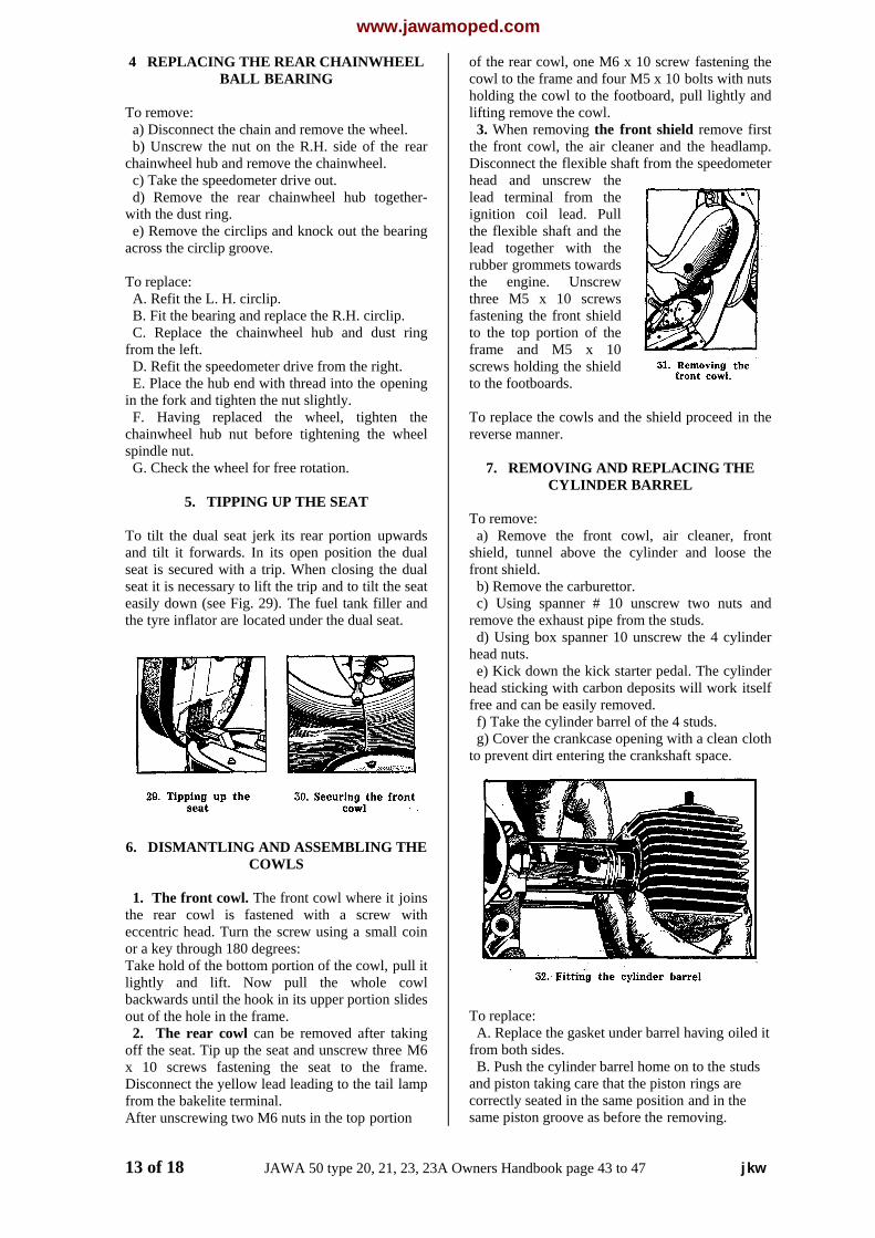
of the rear cowl, one M6 x 10 screw fastening thecowl to the frame and four M5 x 10 bolts with nutsholding the cowl to the footboard, pull lightly andlifting remove the cowl. 3. When removing the front shield remove firstthe front cowl, the air cleaner and the headlamp.Disconnect the flexible shaft from the speedometerhead and unscrew thelead terminal from theignition coil lead. Pullthe flexible shaft and thelead together with therubber grommets towardsthe engine. Unscrewthree M5 x 10 screwsfastening the front shieldto the top portion of theframe and M5 x 10screws holding the shieldto the footboards.
To replace the cowls and the shield proceed in thereverse manner.
7. REMOVING AND REPLACING THECYLINDER BARREL
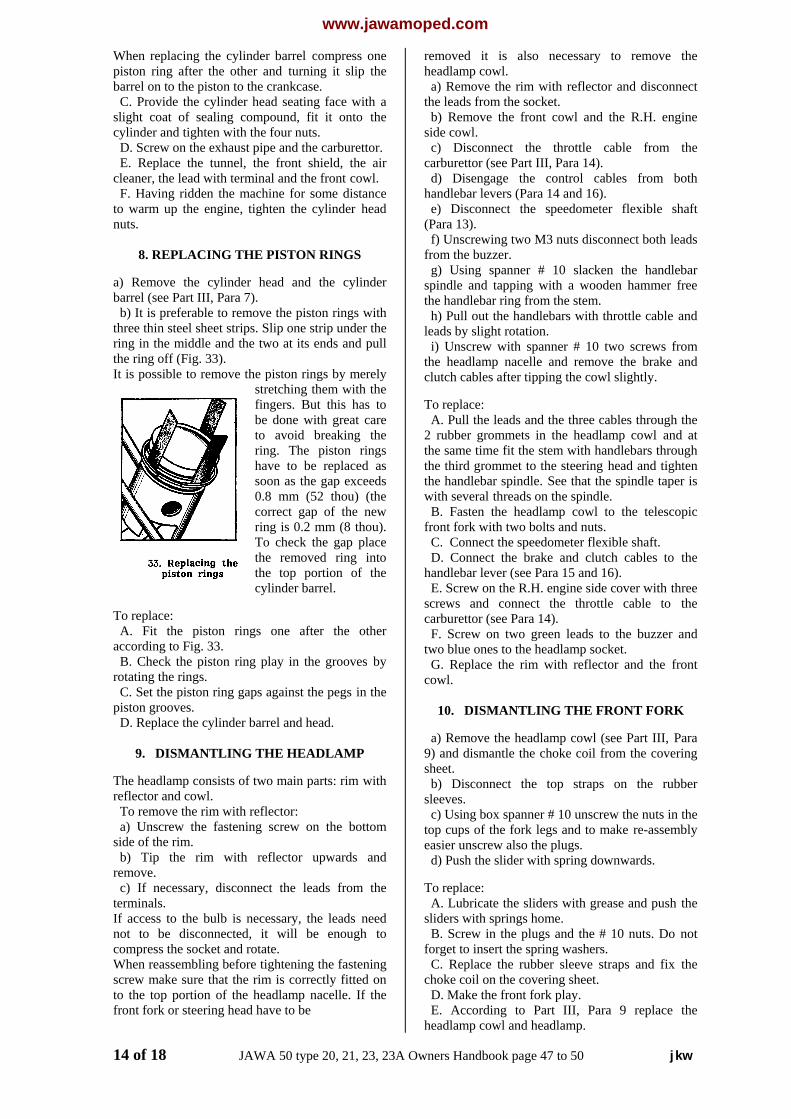
To remove: a) Remove the front cowl, air cleaner, frontshield, tunnel above the cylinder and loose thefront shield. b) Remove the carburettor. c) Using spanner # 10 unscrew two nuts andremove the exhaust pipe from the studs. d) Using box spanner 10 unscrew the 4 cylinderhead nuts. e) Kick down the kick starter pedal. The cylinderhead sticking with carbon deposits will work itselffree and can be easily removed. f) Take the cylinder barrel of the 4 studs. g) Cover the crankcase opening with a clean clothto prevent dirt entering the crankshaft space.
To replace: A. Replace the gasket under barrel having oiled itfrom both sides. B. Push the cylinder barrel home on to the studsand piston taking care that the piston rings arecorrectly seated in the same position and in thesame piston groove as before the removing.
13 of 18 JAWA 50 type 20, 21, 23, 23A Owners Handbook page 43 to 47 jkw
www.jawamoped.com
When replacing the cylinder barrel compress onepiston ring after the other and turning it slip thebarrel on to the piston to the crankcase. C. Provide the cylinder head seating face with aslight coat of sealing compound, fit it onto thecylinder and tighten with the four nuts. D. Screw on the exhaust pipe and the carburettor. E. Replace the tunnel, the front shield, the aircleaner, the lead with terminal and the front cowl. F. Having ridden the machine for some distanceto warm up the engine, tighten the cylinder headnuts.
8. REPLACING THE PISTON RINGS
a) Remove the cylinder head and the cylinderbarrel (see Part III, Para 7). b) It is preferable to remove the piston rings withthree thin steel sheet strips. Slip one strip under thering in the middle and the two at its ends and pullthe ring off (Fig. 33).It is possible to remove the piston rings by merely
stretching them with thefingers. But this has tobe done with great careto avoid breaking thering. The piston ringshave to be replaced assoon as the gap exceeds0.8 mm (52 thou) (thecorrect gap of the newring is 0.2 mm (8 thou).To check the gap placethe removed ring intothe top portion of thecylinder barrel.
To replace: A. Fit the piston rings one after the otheraccording to Fig. 33. B. Check the piston ring play in the grooves byrotating the rings. C. Set the piston ring gaps against the pegs in thepiston grooves. D. Replace the cylinder barrel and head.
9. DISMANTLING THE HEADLAMP
The headlamp consists of two main parts: rim withreflector and cowl. To remove the rim with reflector: a) Unscrew the fastening screw on the bottomside of the rim. b) Tip the rim with reflector upwards andremove. c) If necessary, disconnect the leads from theterminals.If access to the bulb is necessary, the leads neednot to be disconnected, it will be enough tocompress the socket and rotate.When reassembling before tightening the fasteningscrew make sure that the rim is correctly fitted onto the top portion of the headlamp nacelle. If thefront fork or steering head have to be
removed it is also necessary to remove theheadlamp cowl. a) Remove the rim with reflector and disconnectthe leads from the socket. b) Remove the front cowl and the R.H. engineside cowl. c) Disconnect the throttle cable from thecarburettor (see Part III, Para 14). d) Disengage the control cables from bothhandlebar levers (Para 14 and 16). e) Disconnect the speedometer flexible shaft(Para 13). f) Unscrewing two M3 nuts disconnect both leadsfrom the buzzer. g) Using spanner # 10 slacken the handlebarspindle and tapping with a wooden hammer freethe handlebar ring from the stem. h) Pull out the handlebars with throttle cable andleads by slight rotation. i) Unscrew with spanner # 10 two screws fromthe headlamp nacelle and remove the brake andclutch cables after tipping the cowl slightly.
To replace: A. Pull the leads and the three cables through the2 rubber grommets in the headlamp cowl and atthe same time fit the stem with handlebars throughthe third grommet to the steering head and tightenthe handlebar spindle. See that the spindle taper iswith several threads on the spindle. B. Fasten the headlamp cowl to the telescopicfront fork with two bolts and nuts. C. Connect the speedometer flexible shaft. D. Connect the brake and clutch cables to thehandlebar lever (see Para 15 and 16). E. Screw on the R.H. engine side cover with threescrews and connect the throttle cable to thecarburettor (see Para 14). F. Screw on two green leads to the buzzer andtwo blue ones to the headlamp socket. G. Replace the rim with reflector and the frontcowl.
10. DISMANTLING THE FRONT FORK
a) Remove the headlamp cowl (see Part III, Para9) and dismantle the choke coil from the coveringsheet. b) Disconnect the top straps on the rubbersleeves. c) Using box spanner # 10 unscrew the nuts in thetop cups of the fork legs and to make re-assemblyeasier unscrew also the plugs. d) Push the slider with spring downwards.
To replace: A. Lubricate the sliders with grease and push thesliders with springs home. B. Screw in the plugs and the # 10 nuts. Do notforget to insert the spring washers. C. Replace the rubber sleeve straps and fix thechoke coil on the covering sheet. D. Make the front fork play. E. According to Part III, Para 9 replace theheadlamp cowl and headlamp.
14 of 18 JAWA 50 type 20, 21, 23, 23A Owners Handbook page 47 to 50 jkw

www.jawamoped.com
11. PIVOTED REAR FORK
Before dismantling the pivoted rear fork carry outthe following operations: 1. Remove the rear wheel (Part III, Para 2). 2. Remove the rear chainwheel (Part III, Para 6).
To dismantle: a) Slacken the bolts holding the suspension unitson both sides of the pivoted rear fork. b) Using a press drive out the pivoted fork pivotfrom the rubber blocks which completes thedismantling.To reassemble proceed in a reverse manner.It is recommended to replace the pivoted rear forkonly in a repair shop.
12. REPLACING THE SPEEDOMETERFLEXIBLE SHAFT
To dismantle: a) Remove the front and rear cowl. b) Remove the headlamp, unscrew from thespeedometer head the flexible shaft knurled nutand remove the shaft through the opening in thefront shield together with the rubber grommettowards the engine. c) Remove the chainguard unscrewing twoscrews with spanner # 9. d) On the pivoted fork R.H. arm. Unscrew the nutwith spanner # 14 and remove the clip. e) Unscrew the knurled nut on the speedometerdrive housing on the rear wheel and remove theshaft.To reassemble proceed in reverse manner.Note: If the flexible shaft cable breaks but thecasing in not damaged it is enough to replace thecable. When replacing the cable it will benecessary only to remove the headlamp, tounscrew the knurled nuts on both ends of theeasing and out the broken cable. The oiled newcable can be fitted from either end of the casing.
13. REPLACING THE THROTTLE CABLE
To remove: a) Remove theheadlamp and the frontcowl. b) Unscrew thecarburettor mixingchamber top and pull itout together with thethrottle valve. Havingslackened the nut, screwthe throttle cableadjusting screw rightinto the chamber top. c) Compress the springdisconnect the throttlecable and remove thethrottle valve togetherwith the top.
d) Slacken the two studs in the twist gripretention cap. e) Turn the twist grip so as to enable unscrewingof the screw securing the plug in the handlebarthrough the side opening. Pull off the grip togetherwith the plug. f) Lift the catch link and remove the throttle cableend. Pull out the retention cap together with thethrottle cable and casing.
To replace:A. Pull the cable with casing through the R.H.handlebar and headlamp cowl.B. Connect the cable end in the retention capgroove and fit the retention cap on the handlebar.C. Slip the cable end into the catch link whichshould be inserted into the handlebar groove.D. Connect the other end of the cable to thecarburettor top.E. Pull the cable end until the catch link comes to astop at the retention cap. Fit the spring and throttlevalve to the cable.F. Fit the throttle valve into the carburettor bodyand screw on the top.G. Slip the twist grip and plug onto the handlebarand screw the plug to the handlebar trough thetwist grip hole.H. Push the retention cap towards the twist grip soas to take up the axial play and secure bytightening the rear stud.I. With the front stud, set the required ease ofrotation of the twist grip and check its operation(Fig. 54).
14. REPLACING THE CLUTCH CABLE
To remove: a) Dismantle the frontcowl, headlight andcover from R.H. lid(fig.no.35) b) Depress thedisengaging lever ofclutch on the engineand put out the litz wirefrom the capture. c) Put out the supporttray from the clutchlever holder and byrotating the litz wiredisengage the rollerfrom the clutch lever.
To replace:When replacing it is necessary to lubricate the wirewith oil. To replace proceed in the reverse mannerand after refitting the control cable adjust theclutch as described in Part II, Para 6.
15 of 18 JAWA 50 type 20, 21, 23, 23A Owners Handbook page 51 to 55 jkw

www.jawamoped.com
15. REPLACING THE BRAKE CABLE
To replace: a) When replacing the control cable completeunscrew the bowden cable nut and take thebowden cable off the brake cams lever. b) Remove the headlamp. Free the front brakecable from the handlebar lever in the same manneras the clutch cable. c) Free the rear wheel brake cable with thescrewdriver slackening the screw through the holein the L.H. floor board. To replace proceed in reverse manner.
16. REMOVING THE ENGINE FROMTHE FRAME
a) Remove the cowl (Part III, Para 6) and the aircleaner. b) Disconnect the fuel line, the throttle and clutchcable and the gear change pedal rod. c) Disconnect the chain. d) Unscrew the 4 M8 fastening bolts. e) Take out the engine.
To replace: A. Place the engine in the frame and tighten the 4M8 bolts. B. Replace the chain, the fuel line, the throttleand clutch cable and the gear change pedal rod. C. Fit the cowls (Part III, Para 6). D. Check the running of the engine and havingridden a short distance tighten all screws, bolts andnuts.
SEIZURE OF STARTING SEGMENT
In case of seizure of starting segment or in case ofineffective depressing the starting lever to avoidthe quick wear and damaging the startingtransmission the following procedure is required: 1. Starting lever be returned to the formerposition 2. Be engaged the bottom gear 3. Move the vehicle ahead by some cms (to makerotate the starting pinion) 4. Put out the bottom gear 5. Repeat the starting
CLUTCH COVER FALLS OUT
Falling out the clutch bowden cover is caused byincorrect assembly and dismantling andsimultaneously also the tear of catch nose takesplace. To eliminate the failure the followingprocedure is required:When dismantling according to the fig. no, a 1. By means of screwdriver put out the coverfrom one groove 2. The cover remove from the R. H. cover.
When assembly according to the figure no. b 1. The cover is to be put into one groove and tobe flush with R. H. cover face. 2. The cover be pressed in the downwarddirection by such a force to engage into reliablyinto second groove.
16 of 18 JAWA 50 type 20, 21, 23, 23A Owners Handbook page 55 to 57 jkw
www.jawamoped.com
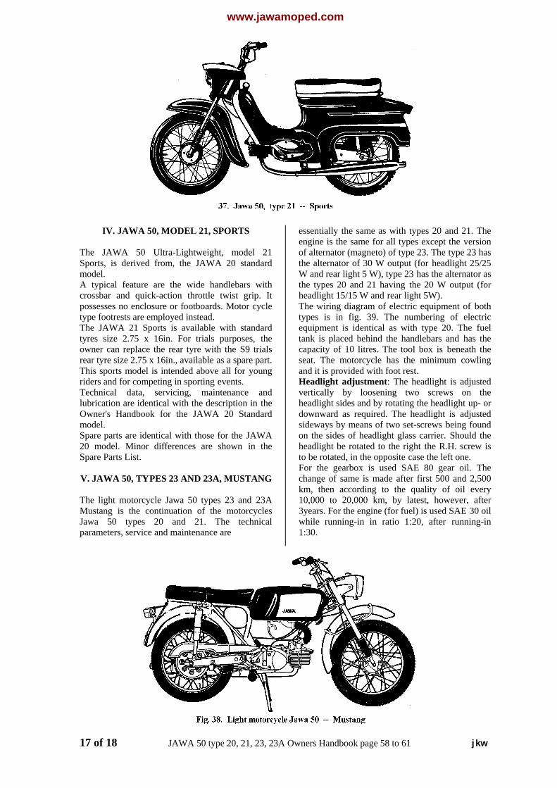
IV. JAWA 50, MODEL 21, SPORTS
The JAWA 50 Ultra-Lightweight, model 21Sports, is derived from, the JAWA 20 standardmodel.A typical feature are the wide handlebars withcrossbar and quick-action throttle twist grip. Itpossesses no enclosure or footboards. Motor cycletype footrests are employed instead.The JAWA 21 Sports is available with standardtyres size 2.75 x 16in. For trials purposes, theowner can replace the rear tyre with the S9 trialsrear tyre size 2.75 x 16in., available as a spare part.This sports model is intended above all for youngriders and for competing in sporting events.Technical data, servicing, maintenance andlubrication are identical with the description in theOwner's Handbook for the JAWA 20 Standardmodel.Spare parts are identical with those for the JAWA20 model. Minor differences are shown in theSpare Parts List.
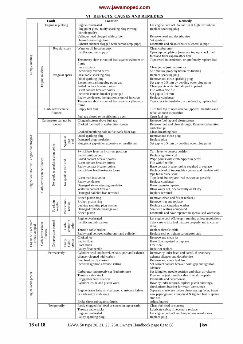
V. JAWA 50, TYPES 23 AND 23A, MUSTANG
The light motorcycle Jawa 50 types 23 and 23AMustang is the continuation of the motorcyclesJawa 50 types 20 and 21. The technicalparameters, service and maintenance are
essentially the same as with types 20 and 21. Theengine is the same for all types except the versionof alternator (magneto) of type 23. The type 23 hasthe alternator of 30 W output (for headlight 25/25W and rear light 5 W), type 23 has the alternator asthe types 20 and 21 having the 20 W output (forheadlight 15/15 W and rear light 5W).The wiring diagram of electric equipment of bothtypes is in fig. 39. The numbering of electricequipment is identical as with type 20. The fueltank is placed behind the handlebars and has thecapacity of 10 litres. The tool box is beneath theseat. The motorcycle has the minimum cowlingand it is provided with foot rest.Headlight adjustment: The headlight is adjustedvertically by loosening two screws on theheadlight sides and by rotating the headlight up- ordownward as required. The headlight is adjustedsideways by means of two set-screws being foundon the sides of headlight glass carrier. Should theheadlight be rotated to the right the R.H. screw isto be rotated, in the opposite case the left one.For the gearbox is used SAE 80 gear oil. Thechange of same is made after first 500 and 2,500km, then according to the quality of oil every10,000 to 20,000 km, by latest, however, after3years. For the engine (for fuel) is used SAE 30 oilwhile running-in in ratio 1:20, after running-in1:30.
17 of 18 JAWA 50 type 20, 21, 23, 23A Owners Handbook page 58 to 61 jkw
www.jawamoped.comVI DEFECTS, CAUSES AND REMEDIES
Fault Location RemedyEngine is pinking Engine overheated
Plug point glow, faulty sparking plug (wrongthermic grade)Cylinder head clogged with carbonOver-advanced ignitionExhaust silencer clogged with carbon (esp. pipe)
Let engine cool off, do not run at high revolutionsReplace sparking plug
Remove head and decarboniseSet ignitionDismantle and clean exhaust silencer, & pipe
Regular spark Water or oil in carburettorInsufficient fuel supply
Temporary short circuit of lead against cylinder orframeLean mixtureIncorrectly mixed petrol
Clean carburettorOpen tap completely (reserve), top up, check fuelfeed and filler cap breather holeTape crack in insulation, or, preferably replace lead
Clean jet, adjust carburettorStir mixture properly before re-fuelling
Lum
py ru
nnin
g
Engi
ne m
isfir
es
Irregular spark Unsuitable sparking plugOiled sparking plugExcessive sparking plug point gapSoiled contact breaker pointsBurnt contact breaker pointsIncorrect contact breaker point gapFaulty condenser, the ignition is out of functionTemporary short circuit of lead against cylinder orframe
Replace sparking plugRemove and clean sparking plugSet gap to 0.5 mm by bending outer plug pointClean points with cloth dipped in petrolFile with a fine fileSet gap to 0.4 mmReplace condenserTape crack in insulation, or preferably, replace lead
Carburettor can beflooded
Empty fuel tank
Fuel tap closed or insufficiently open
Turn fuel tap to open reserve (approx. 18 miles) andrefuel as soon as possibleOpen fuel tap
Carburettor can not beflooded
Clogged screen above fuel tapChoked fuel feed or carburettor screen
Choked breathing hole in fuel tank filler cap
Remove fuel tap and clean screenRemove feed and blow through. Remove carburettorand clean jetClean breathing hole
Spar
k at
lead end
Oiled sparking plugDamaged plug insulationPlug point gap either excessive or insufficient
Remove and clean plugReplace plugSet gap to 0.5 mm by bending outer plug point
No
spar
k at
spar
king
plu
g po
ints
No
spar
k at
lead
end
Switch box lever in incorrect positionFaulty ignition coilSoiled contact breaker pointsBurnt contact breaker pointsFaulty contact breaker pointsSwitch box lead broken or loose
Burnt lead insulationFaulty condenserDamaged stator winding insulationWater in contact breakerDamaged bakelite lead terminal
Turn lever to correct positionReplace ignition coilWipe points with cloth dipped in petrolFile with fine fileHave contact breaker points repaired or replaceReplace lead, if impossible connect and insulate withtape but replace soonTape lead, but replace lead as soon as possibleReplace condenserHave magneto repairedBlow water out, dry carefully or let dryReplace terminal
Engi
ne w
ill n
ot fi
re –
eng
ine
has s
topp
ed
Car
bure
ttor c
an b
e flo
oded
Spar
king
regu
lar
Poor
com
p-re
ssio
n
Seized piston ringBroken piston ringLeaking sparking plug washerDamaged cylinder head gasketSeized piston
Remove, clean and fit (or replace)Remove ring and replaceReplace sparking plug washerSeal with sealing compoundDismantle and have repaired in specialised workshop
Car
b-ur
etto
r in
orde
r
Engine overheatedInsufficient lubrication
Throttle cable brokenFaulty seal between carburettor and cylinder
Let engine cool off, keep it running at low revolutionsTake care to mix fuel mixture properly and at correctratioReplace throttle cableReplace seal or tighten carburettor stub
Engi
ne w
ill n
ot st
art
or h
as st
oppe
d
Car
bure
ttor c
an b
eflo
oded
Com
pres
sion
nor
mal
Faul
tyC
arb-
uret
tor Choked jet
Faulty floatFloat stuckFaulty float needle
Remove and clean jetHave float repaired or replaceFree floatRepair or replace
Permanently Cylinder head and barrel, exhaust port and exhaustsilencer clogged with carbonFuel feed partly chokedIncorrect ignition advance setting
Carburettor incorrectly set (bad mixture)Throttle valve stuckClogged exhaust silencerCylinder inside and piston worn
Engine draws false air (damaged crankcase halvesor carburettor stub seal)
Brake shoes rub against drums
Remove cylinder head and barrel, if necessaryexhaust silencer and decarboniseRemove and clean fuel feedSet correct contact breaker point gap and ignitionadvanceSet idling jet, needle position and clean air cleanerFree and adjust throttle valve to work properlyDismantle and decarboniseHave cylinder rebored, replace piston and rings,check piston bearing for wear (workshop)Separate crankcase halves clean seating faces, insertnew paper gasket, compound & tighten fast. Replacestub sealAdjust brakes
Engi
ne la
cks p
ower
Temporarily Partly clogged fuel feed or screen in tap or carb.Throttle cable sticksEngine overheatedFaulty sparking plug
Clean fuel feed or screensLubricate cable, if necessary replaceLet engine cool off and keep at low revolutionsReplace plug
18 of 18 JAWA 50 type 20, 21, 23, 23A Owners Handbook page 63 to 68 jkw