Embed Size (px)
Citation preview

GE Healthcare
OPERATING DOCUMENTATION
2349182-100Rev 12
131
LightSpeed 5.XInstallation Manual
(Book 2 of 2)

GE HEALTHCAREDIRECTION 2349182-100, REVISION 12 LIGHTSPEED 5.X INSTALLATION MANUAL
Page 132
Book 2 of 2: Electrical Calibration, Integration & Testing Pages # - 272
EffectivityThe information in this manual applies to the following LightSpeed 5.X CT Systems:• LightSpeed Pro16• LightSpeed RT• LightSpeed 16• LightSpeed Ultra• LightSpeed Plus

GE HEALTHCAREDIRECTION 2349182-100, REVISION 12 LIGHTSPEED 5.X INSTALLATION MANUAL
Table of Contents Page 133
Table of Contents: Book 2
Book
2 T
OC
Chapter 4Electrical Introduction......................................................................................... 141
Section 1.0 Introduction .................................................................................................... 141
Section 2.0Review Mechanical Hand Off Material.......................................................... 141
Section 3.0Training ........................................................................................................... 141
Section 4.0Required FE Common Tools and Supplies.................................................. 1424.1 FE Calibration and Service Tool List ............................................................................. 1424.2 Electrical Tools .............................................................................................................. 1424.3 Image Quality Calibration Tools..................................................................................... 1424.4 Detector Service Tools .................................................................................................. 1424.5 Optional Tools................................................................................................................ 1434.6 Safety Materials ............................................................................................................. 1434.7 Cleanliness .................................................................................................................... 143
Section 5.0Requirements/Assumptions.......................................................................... 144
Chapter 5Electrical Integration and Safety Verifications ................................................. 145
Section 1.0Electrical Power ON & Ground Checks........................................................ 1451.1 Required Tools .............................................................................................................. 1451.2 Initial PDU Configuration ............................................................................................... 146
1.2.1 Circuit Breakers ................................................................................................ 1461.2.2 Relay Board ...................................................................................................... 1461.2.3 Power Switches ................................................................................................ 1471.2.4 Hardware and Connection Check..................................................................... 1471.2.5 Covers .............................................................................................................. 147
1.3 Suite Emergency Off Checks......................................................................................... 1471.4 Line Transformer Settings ............................................................................................. 147
1.4.1 Requirements ................................................................................................... 1471.4.2 Line Input Conditions ........................................................................................ 147
1.5 System Power Up .......................................................................................................... 1491.6 Emergency Stop Check ................................................................................................. 150
Section 2.0Computer Integration..................................................................................... 1522.1 Introduction .................................................................................................................... 1522.2 System Configuration Data Sheets................................................................................ 1522.3 Restore System State.................................................................................................... 152

GE HEALTHCAREDIRECTION 2349182-100, REVISION 12 LIGHTSPEED 5.X INSTALLATION MANUAL
Page 134 Table of Contents
2.4 Install Customer Options............................................................................................... 1532.4.1 Software ........................................................................................................... 1532.4.2 Camera ............................................................................................................ 154
2.5 Monitor Setup................................................................................................................ 1552.6 Contrast/Brightness Black & White Adjustment Procedure........................................... 1552.7 Shut Down Application .................................................................................................. 1562.8 Check/Set Date and Time ............................................................................................. 1562.9 Reconfig the OC............................................................................................................ 156
2.9.1 Overview .......................................................................................................... 1562.9.2 Procedure......................................................................................................... 157
2.10 Applications Start-Up .................................................................................................... 1622.11 GRE Console Boot-up Flow Chart ................................................................................ 163
Section 3.0Enable CT Number Range (RT Only) ............................................................ 164
Section 4.0Table Gantry Integration ................................................................................ 1654.1 Introduction ................................................................................................................... 1654.2 Check Alignment Lights ................................................................................................ 165
4.2.1 Room Light Adjustment.................................................................................... 1654.2.2 Turning the Alignment Lights ON ..................................................................... 1654.2.3 Internal Axial Lights.......................................................................................... 1664.2.4 External Axial to Internal Axial Distance .......................................................... 1664.2.5 Coronal Lights .................................................................................................. 1664.2.6 Turn Lights OFF ............................................................................................... 166
4.3 Autovoice/Intercom Check ............................................................................................ 1674.3.1 Requirements................................................................................................... 1674.3.2 Patient Speaker................................................................................................ 1674.3.3 Operator Console Speaker .............................................................................. 1674.3.4 Autovoice Volume ............................................................................................ 167
4.4 CT System X-Ray ON Indicators, Cautions & Warning Labels..................................... 1684.4.1 Check And Install System Warning Labels ...................................................... 1684.4.2 Console ............................................................................................................ 168
4.4.2.1 On The SCIM ................................................................................... 1684.4.2.2 On The Keyboard............................................................................. 168
4.4.3 Gantry .............................................................................................................. 1684.4.3.1 Scan Window Laser Labels ............................................................. 1684.4.3.2 Laser Window Labels....................................................................... 1684.4.3.3 Front Cover Laser Warning.............................................................. 1684.4.3.4 Front cover Information Labels ........................................................ 1684.4.3.5 Gantry System GIB (Rating) label.................................................... 168
4.4.4 Table - 2000mm ............................................................................................... 1684.4.4.1 Front Side Cover - Pinch Hazard Warning Label ............................. 1684.4.4.2 Back Cradle Pan - Pinch Hazard Warning Label ............................. 168
4.4.5 Table - 1700mm ............................................................................................... 1694.4.5.1 Front Side Cover - Pinch Hazard Warning Label ............................. 1694.4.5.2 Rear Side Cover - Pinch Hazard Warning Label ............................. 1694.4.5.3 Back Cradle Pan - Pinch Hazard Warning Label ............................. 169
4.4.6 NGPDU ............................................................................................................ 1694.4.6.1 Front Cover - Emergency Off label .................................................. 1694.4.6.2 Front Cover - Gantry Enable Label .................................................. 169

GE HEALTHCAREDIRECTION 2349182-100, REVISION 12 LIGHTSPEED 5.X INSTALLATION MANUAL
Table of Contents Page 135
Book
2 T
OC
4.4.6.3 Front Cover - Power On Label.......................................................... 1694.4.7 Accessories ...................................................................................................... 169
4.4.7.1 Table Foot Extender Label ............................................................... 1694.4.7.2 Coronal Head Holder Label .............................................................. 1694.4.7.3 Sagittal Head Holder Label............................................................... 1694.4.7.4 Accessory Tray Label ....................................................................... 1694.4.7.5 IV Pole Label .................................................................................... 169
4.4.8 Documentation - Verification............................................................................. 1694.5 Check Warning Labels................................................................................................... 170
4.5.1 On SCIM........................................................................................................... 1704.5.2 On Gantry ......................................................................................................... 1704.5.3 On Laser ........................................................................................................... 170
4.6 Process Product Locator Cards..................................................................................... 1704.7 Install Service Cabinet ................................................................................................... 1704.8 Check X-Ray Lights ....................................................................................................... 1704.9 Mechanical Characterization ......................................................................................... 171
4.9.1 Alignment Light Characterization...................................................................... 1714.9.2 Alignment Light Characterization...................................................................... 171
4.10 Interference Test............................................................................................................ 1714.10.1 Verify Table Elevation - All Systems................................................................. 1724.10.2 Tests for Pro16, LS16, Ultra & Plus Systems ................................................... 173
4.10.2.1 Position Tilt, Move Table to Interference Limit (Except RT) ............. 1734.10.2.2 Position Table, Move Tilt to Interference Limit (Except RT) ............. 1744.10.2.3 Tilt Limits When Table Below Scan Plane Lower Limit (Except RT) 174
4.10.3 Tests for RT Systems Only............................................................................... 1764.10.3.1 Position Tilt, Move Table to Interference Limit (RT) ......................... 1764.10.3.2 Position Table, Move Tilt to Interference Limit (RT) ......................... 1774.10.3.3 Tilt Limits When Table Below Scan Plane Lower Limit (RT) ............ 1774.10.3.4 Gantry Rotational Characterization (RT Systems Only) ................... 1794.10.3.5 Alignment Light Characterization (RT Systems Only) ...................... 179
4.10.4 Alignment Light Characterization - All Systems................................................ 1814.10.4.1 Overview........................................................................................... 1814.10.4.2 Procedure ......................................................................................... 181
Chapter 6Image Quality ....................................................................................................... 183
Section 1.0Introduction .................................................................................................... 183
Section 2.0Calibration Process........................................................................................ 1842.1 Reference Procedures................................................................................................... 184
2.1.1 Scanning with Service Protocols ...................................................................... 1842.1.2 Center Phantom................................................................................................ 184
2.2 Prepare the QA Phantom .............................................................................................. 1842.3 Calibration Process Introduction.................................................................................... 184
Section 3.0Table/Gantry Alignment Procedure .............................................................. 1853.1 Conditions...................................................................................................................... 185

GE HEALTHCAREDIRECTION 2349182-100, REVISION 12 LIGHTSPEED 5.X INSTALLATION MANUAL
Page 136 Table of Contents
3.2 Procedure...................................................................................................................... 185
Section 4.0Tube Warm Up and Fast Cal .......................................................................... 186
Section 5.0Tomographic Plane Indication ...................................................................... 187
Section 6.0Image Series.................................................................................................... 1886.1 Scan Protocol................................................................................................................ 1886.2 Data Recording: Means and Standard Deviation.......................................................... 1886.3 Term Definitions and Screens....................................................................................... 1886.4 48cm Phantom Image Series Image Performance Verification .................................... 190
6.4.1 Acquiring the 48cm Phantom Image Series..................................................... 1906.4.2 Image Performance Verification....................................................................... 191
6.4.2.1 Series Means (AvXo-AvXc and AvSDo) & Center Smudge............. 1916.4.2.2 Band and Streak Artifact .................................................................. 191
6.4.3 Failure Recommended Actions ........................................................................ 1936.4.3.1 Series Means (AvXo-AvXc or AvSDo) Failure Recovery ................ 1936.4.3.2 Center Smudge Failure Recovery.................................................... 1936.4.3.3 Band or Streak Artifact Failure Recovery......................................... 194
6.5 20cm QA Phantom Image Series Image Performance Verification .............................. 1946.5.1 Acquiring the 20cm QA Phantom Image Series............................................... 1946.5.2 20cm QA Phantom Image Series Image Performance Verification ................. 1956.5.3 Failure Recommended Actions ........................................................................ 199
6.5.3.1 1st Image Series (4 Image MTF Average) Failure Recovery ........... 1996.5.3.2 2nd Image Series (Visible Lines) Failure Recovery.......................... 1996.5.3.3 3rd Image Series (Visible Holes) Failure Recovery .......................... 2006.5.3.4 4th Image Series Failure Recovery .................................................. 200
Section 7.0System Functional Test ................................................................................. 202
Section 8.0Save System State.......................................................................................... 202
Chapter 7Customer Options Installation & Verification................................................... 203
Section 1.0CT Options ...................................................................................................... 203
Section 2.0Install Options................................................................................................. 2032.1 Camera (Filming Device) .............................................................................................. 2032.2 Injector .......................................................................................................................... 2042.3 Advantage Workstation (AW)........................................................................................ 2042.4 Other Options................................................................................................................ 204
Section 3.0DICOM Network Introduction......................................................................... 205

GE HEALTHCAREDIRECTION 2349182-100, REVISION 12 LIGHTSPEED 5.X INSTALLATION MANUAL
Table of Contents Page 137
Book
2 T
OC
Section 4.0Before You Start ............................................................................................. 2064.1 Network Physical Requirements.................................................................................... 2064.2 Network Identity Information .......................................................................................... 2064.3 Scanner to DICOM Remote Hosts Network Information ............................................... 2064.4 Scanner to DICOM HIS/RIS Interface Network Information .......................................... 2064.5 Scanner to DICOM Printers Network Information.......................................................... 207
Section 5.0Declaring the System on the Hospital Network........................................... 2085.1 Enter Configuration Routine .......................................................................................... 2085.2 Configure Network Settings ........................................................................................... 2095.3 Initiate System Reconfiguration ..................................................................................... 210
Section 6.0Declaring Remote Hosts on the CT System ................................................ 2116.1 Enter Remote Host Configuration Screen ..................................................................... 2116.2 Declaring Advantage NET Remote Hosts on the Scanner ............................................ 2116.3 Declaring DICOM Remote Hosts on the CT Scanner.................................................... 212
Section 7.0Declaring the CT System on Remote Hosts ................................................ 2147.1 Declaring the Scanner on Advantage NET Protocol Devices/Systems ......................... 2147.2 Declaring the Scanner on DICOM Protocol Devices/Systems ...................................... 214
Section 8.0DICOM HIS/RIS Setup .................................................................................... 2158.1 Prerequisites.................................................................................................................. 2158.2 Loading ConnectPRO Software Option on the CT System ........................................... 215
Section 9.0DICOM Filming Devices Setup...................................................................... 2179.1 Prerequisites.................................................................................................................. 2179.2 Declaring DICOM Filming Devices on the CT System .................................................. 2179.3 Troubleshooting Tips ..................................................................................................... 228
Section 10.0Teleradiology (Framegrabber Type) Systems & Aux. Monitors................. 23010.1 Introduction .................................................................................................................... 23010.2 Auxiliary Monitors Setup ................................................................................................ 23010.3 CT Analog Filming Interface Specs (Video & Serial) ..................................................... 232
Section 11.0Network Connections .................................................................................... 234
Chapter 8Patient Touch Leakage Test ............................................................................... 239
Section 1.0Personnel Requirements ............................................................................... 239
Section 2.0Overview ......................................................................................................... 239
GE HEALTHCAREDIRECTION 2349182-100, REVISION 12 LIGHTSPEED 5.X INSTALLATION MANUAL
Page 138 Table of Contents
Section 3.0Preliminary Requirements ............................................................................. 2393.1 Tools and Test Equipment ............................................................................................ 2393.2 Safety ............................................................................................................................ 2393.3 Required Conditions...................................................................................................... 240
Section 4.0Procedure........................................................................................................ 2404.1 Patient Touch Leakage Current Test Procedure........................................................... 2404.2 Ground Resistance Checks Procedure (done during mechanical install) ..................... 243
Section 5.0Finalization...................................................................................................... 243
Chapter 9Forms and Checklists......................................................................................... 245
Section 1.0Mechanical Vendor Installation List.............................................................. 247
Section 2.0Electrical Calibration Installation Checklist ................................................. 249
Section 3.0GE Form 4879 Installation Data Verification ................................................ 2513.1 Installation Site History.................................................................................................. 251
3.1.1 RECORDS KEEPING AND DOCUMENTATION - IMPORTANT!.................... 2513.1.2 Component Tractability - IMPORTANT!........................................................... 2513.1.3 Installation Procedures Traceability - IMPORTANT!........................................ 2513.1.4 Installation Test & Tools Traceability - IMPORTANT! ...................................... 252
3.2 System X-Ray Indicators and Warning Labels.............................................................. 2523.2.1 X-Ray On Indicators......................................................................................... 2523.2.2 Operator Indicators - HHS Requirement .......................................................... 253
3.3 Warning Labels ............................................................................................................. 2533.3.1 Laser Warning labels ....................................................................................... 2533.3.2 Operator Use Warning Label - SCIM ............................................................... 2533.3.3 Appropriate Language Warning Labels Verification......................................... 254
3.4 Tomographic Plane Indication Accuracy....................................................................... 2543.5 Table/Gantry Alignment Procedure............................................................................... 2543.6 Check Alignment Lights - Test ...................................................................................... 2553.7 Interference Test ........................................................................................................... 2553.8 System Functional Test................................................................................................. 2563.9 IQ Section - 5.X Image Quality Series .......................................................................... 2563.10 Documentation Section - System Paperwork & Product Locator.................................. 256
3.10.1 Installation Verification ..................................................................................... 2563.10.2 Product Locator................................................................................................ 2563.10.3 Regulatory Information Distribution.................................................................. 257
Section 4.0Install Completion Checklist.......................................................................... 2594.1 CT System .................................................................................................................... 2594.2 CT Options .................................................................................................................... 259

GE HEALTHCAREDIRECTION 2349182-100, REVISION 12 LIGHTSPEED 5.X INSTALLATION MANUAL
Table of Contents Page 139
Book
2 T
OC
4.3 System Cleanup ............................................................................................................ 2594.4 Dollies Return ................................................................................................................ 2594.5 Install Completion Material Checks ............................................................................... 260
Section 5.0Electronic Forms............................................................................................ 261
Appendix EAdditional Characterization Procedures ........................................................... 263
Appendix FSystem Configuration Data Sheets.................................................................... 265
Appendix GSymbols................................................................................................................ 269

GE HEALTHCAREDIRECTION 2349182-100, REVISION 12 LIGHTSPEED 5.X INSTALLATION MANUAL
Page 140 Table of Contents
End of TOC

GE HEALTHCAREDIRECTION 2349182-100, REVISION 12 LIGHTSPEED 5.X INSTALLATION MANUAL
Chapter 4 - Electrical Introduction Page 141
4 –
Elec
tric
al In
tro
Chapter 4Electrical Introduction
NOTICE To prevent potential data loss and equipment damage, please do the following:
• Record data collected from procedures in this chapter into Form F4879 when directed, located in Chapter 9 of this book.
• Only use the Installation manual that arrives with your system for installation. Any other revisions of this manual may not exactly match your system.
Section 1.0 Introduction
Use the continuity and ground checks to verify the system power connections have not shorted to ground and that the ground and neutral connections are intact.
Section 2.0Review Mechanical Hand Off Material
Complete the Mechanical Hand Off checklist:
All options were installed. If not, contact your install specialist.
Check for short ships.
Review cable connections with mechanical team.
Complete mechanical vendor evaluation.
Section 3.0Training
This product requires a trained FE to proceed with the calibrations in this section.

GE HEALTHCAREDIRECTION 2349182-100, REVISION 12 LIGHTSPEED 5.X INSTALLATION MANUAL
Page 142 Section 4.0 - Required FE Common Tools and Supplies
Section 4.0Required FE Common Tools and Supplies
4.1 FE Calibration and Service Tool List
Note: Items with a “check” (√) are included in the Install Support Kit.
Special CT Tools used for mechanical alignments:
4.2 Electrical Tools
These tools must be calibrated yearly.
• Fluke 87 DVM or equivalent
• Clamp on amp meter
4.3 Image Quality Calibration Tools
• GE Performance Phantom
• QA Phantom (2206352)
- 24cm (2144721)
- 48cm (2144721-2)
- Phantom Holder
4.4 Detector Service Tools
A DAS/Detector Service Kit (PN 2344539) is included in the Install Support Kit.
• Aero Duster
• AMAX Contact Cleaner
√ 5mm hex bit for 3/8” drive 6" long(Snap-On FAML5E or equivalent)
√ 10mm open-end thin wrench(Snap-On SRSM10 or equivalent)
√ 10mm hex bit for ratchet wrench (ball end) (Snap-On FABM10E or equivalent)
√ 21mm open-end thin wrench(Snap-On LTAM2124 or equivalent)
√ 2.5mm Allen hex bit for ¼" √ 14mm ball hex socket bit for 3/8” drive
• Standard FE Tool Kit √ 14 mm hex socket bit for ½" drive
• Torque Wrench Kit

GE HEALTHCAREDIRECTION 2349182-100, REVISION 12 LIGHTSPEED 5.X INSTALLATION MANUAL
Chapter 4 - Electrical Introduction Page 143
4 –
Elec
tric
al In
tro
4.5 Optional Tools
Needed for warranty recalibration:
• GE HV Bleeder
• Scope with 10X probes
• Beckman CT231 clamp-on Amp probe: 46-194427P228 (Fits up to #2 size wire)
• Beckman CT232 clamp-on Amp probe: 46-194427P270 (Fits #1 size wire and larger)
• Scope Probe-to-bleeder Cable 46-219921G1 (Belden #8422 cable, 30 ft)
• Polaroid type 52 film and developer
• Radial dial indicator (mm or inches) and mounting bracket
• Caliper Dial indicators (mm or inches)
• Ground Rod Tester Clamp on Amp Probe
4.6 Safety Materials
Note: Items with “checks” (√) are included in the Install Support Kit
√ Lockout/Tagout kit, or equivalent
√ Nitrile Rubber Gloves
• Safety Glasses
4.7 Cleanliness
Any dirt on the surface increases leakage current on the filter or converter cards and causes the DAS to fail the drift spec. Wear Nitrile gloves (part number 2207303-6 [large] and 2207303-7 [extra large]) when you handle the DAS, because fingerprints on the board can cause problems during humid conditions. Use only clean, new Nitrile gloves. Do not use hospital grade gloves.
NOTICE NEVER USE AN ERASER TO CLEAN ANY PART OF THE DAS.
DUST COVERS REQUIRED for installations on construction sites.

GE HEALTHCAREDIRECTION 2349182-100, REVISION 12 LIGHTSPEED 5.X INSTALLATION MANUAL
Page 144 Section 5.0 - Requirements/Assumptions
Section 5.0Requirements/Assumptions
• This procedure will be performed by an appropriately trained engineer.
• All stations in a suite must have the same SUITE ID.
• You need the name of all hosts in the suite and their corresponding Internet/Ethernet numbers.
• You need the Internet (IP) addresses the first time you execute a reconfig on the system.
- When you connect the system to a network, contact the system administrator to obtain the IP addresses for all the computers in the suite.
- You also need an IP address for each gateway (second) ethernet board in any OC or IC.
- You can use the default internet number on stand-alone systems (stand-alone = not connected to any network).
• For more detailed information and instructions regarding Network Integration, see Chapter 7 on page 203.

GE HEALTHCAREDIRECTION 2349182-100, REVISION 12 LIGHTSPEED 5.X INSTALLATION MANUAL
Chapter 5 - Electrical Integration and Safety Verifications Page 145
5 –
Inte
g. &
Saf
ety
Chapter 5Electrical Integration and Safety Verifications
NOTICE To prevent potential data loss, please do the following:
• Record data collected from procedures in this chapter into Form F4879 when directed, located in Chapter 9 of this book.
• Only use the Installation manual that arrives with your system for installation. Any other revisions of this manual may not exactly match your system.
Section 1.0Electrical Power ON & Ground Checks
WARNING THIS PROCEDURE MEASURES POTENTIALLY HAZARDOUS VOLTAGES. USE AND FOLLOW LOCKOUT/TAGOUT PROCEDURES.
Figure 5-1 NGPDU
1.1 Required Tools
• Multimeter with a rating of at least 1000 volts
• Multimeter leads with a rating of at least 1000 volts
Mai
ns &
PE
HV
DC
PE
T G
antr
y
Sys
tem
GN
D
CT
Gan
try
OC
PW
R
PW
R fr
om U
PS
PW
R T
O U
PS
Cus
tom
er I/
O
Axi
al D
river
10 14 151211 13 16 179
18 21
19
20
3029
2326
27
KxgKss
Ktg
Ksv
TS1
TS2TS3
TS4
TS5 TS6
F1-3
BR1
CB1
LED
SW
PS
PDU Control Bd
Gro
und B
lock
CB2 CB3 CB4-9
Front View
31
SW
H3 H2 H1
Power Transformer
6 mF
370 VAC
C1
6 mF
370 VAC
C26 mF
370 VAC
C3
2 4 5 6 3 1 2 4 5 6 3 1 2 4 5 6 3 1
6 mF
370 VAC
C4
6 mF
370 VAC
C56 mF
370 VAC
C6
C8C7
24R1R2R3
28
25
24
Rear View

GE HEALTHCAREDIRECTION 2349182-100, REVISION 12 LIGHTSPEED 5.X INSTALLATION MANUAL
Page 146 Section 1.0 - Electrical Power ON & Ground Checks
1.2 Initial PDU Configuration
WARNING THIS PROCEDURE MEASURES POTENTIALLY HAZARDOUS VOLTAGES. USE AND FOLLOW LOCKOUT/TAGOUT PROCEDURES.
1.2.1 Circuit BreakersSet all circuit breakers to OFF
1.2.2 Relay Board
1.) Set SW to the normal position.
2.) When system is already, three lamps are both lighting (refer to Figure 5-2).
Figure 5-2 NGPDU Control Board
Verify SW is in the normal position
DSD 3
DSD 5
DSD 4

GE HEALTHCAREDIRECTION 2349182-100, REVISION 12 LIGHTSPEED 5.X INSTALLATION MANUAL
Chapter 5 - Electrical Integration and Safety Verifications Page 147
5 –
Inte
g. &
Saf
ety
1.2.3 Power SwitchesTurn OFF all power switches on all subsystems
1.2.4 Hardware and Connection CheckUse this step to check mechanical connections and tighten anything that may have shaken loose during shipment. Verify all hardware and connections in the PDU are securely fastened.
1.2.5 CoversInstall, or verify the presence of, all the lexan safety covers.
1.3 Suite Emergency Off Checks
WARNING VERIFY ALL PERSONNEL HAVE CLEARED THE SYSTEM BEFORE YOU TURN ON WALL POWER.
1.) Turn wall power ON to the PDU.
2.) Press the suite emergency off button and verify it turns off wall power to the PDU.
[Typically, this red palm button is located on the wall close to the console, within the scan suite.]
3.) Verify that all “Emergency Off” button are working properly.
4.) Leave power “OFF”
1.4 Line Transformer Settings
1.4.1 Requirements
WARNING MAKE SURE YOU TURNED OFF, TAGGED AND LOCKED THE MAIN WALL POWER BEFORE YOU CHANGE TAPS. FAILURE TO DISCONNECT POWER AT MAIN INPUT MAY RESULT IN ELECTROCUTION. TURN OFF WALL POWER TO CONNECT OR MOVE METER LEADS, OR TO REMOVE OR INSTALL COVERS.
1.4.2 Line Input Conditions
1.) Monitor the No Load Line to Line Voltage at L1, L2, L3, during the workday. Do not record this data during “brown out” conditions.
• Gantry • DAS
• Table • Console
1.) The PDU is shipped configured for 480VAC.
2.) Complete only if your site uses a voltage other than 480VAC.
3.) If PDU is configured for 480VAC, go to 1.5. Otherwise, proceed with Section 1.4.2.

GE HEALTHCAREDIRECTION 2349182-100, REVISION 12 LIGHTSPEED 5.X INSTALLATION MANUAL
Page 148 Section 1.0 - Electrical Power ON & Ground Checks
2.) After you determine the nearest nominal line, verify the tap connections match (refer to Table 5-1 and Figure 5-3 for tap locations).
Figure 5-3 PDU Tap Positions (Rear)
Note: Taps should be shipped as shown for 480 VAC only. For all others, you must move the taps. The tap check should be completed by the mechanical installer.
3.) Verify that the No Load Line to Line Voltage never falls outside the corresponding minimum and maximum values listed in Table 5-1.
4.) Use a 0-750 AC voltmeter of 3/4% accuracy to measure the line-to-line voltages at L1, L2, and L3.
- Verify the highest line-to-line voltage does not exceed 1.02 times the lowest voltage.
- Example: If the lowest voltage equals 474, the highest voltage should not exceed 474 x 1.02 = 483.5 volts.
WARNING THIS PROCEDURE MEASURES POTENTIALLY HAZARDOUS VOLTAGES. USE AND FOLLOW LOCKOUT/TAGOUT PROCEDURES.
H3 H2 H1
2 4 5 6 3 1 2 4 5 6 3 1 2 4 5 6 3 1
Transformer Taps and Jumpers
High Voltage Transformer
NO LOADLine to Line Voltages
TAP CONNECTIONS(All 3 phases must have same the configuration)
Nominal Maximum Range (10%)
Phase A Connection
Phase B Connection
Phase C Connection
480V* 432 to 528* 3-4* 3-4* 3-4*
460V 414 to 506 3-5 3-5 3-5
440V 396 to 484 3-6 3-6 3-6
420V 378 to 462 2-4 2-4 2-4
400V 360 to 440 2-5 2-5 2-5
380V 342 to 418 2-6 2-6 2-6
240V** 216 to 264** 1-4** 1-4** 1-4**
220V** 198 to 242** 1-5** 1-5** 1-5**
200V** 180 to 220** 1-6** 1-6** 1-6**
* Factory Default
** 2326492-3 PDU only
Table 5-1 PDU Line Tap Connections

GE HEALTHCAREDIRECTION 2349182-100, REVISION 12 LIGHTSPEED 5.X INSTALLATION MANUAL
Chapter 5 - Electrical Integration and Safety Verifications Page 149
5 –
Inte
g. &
Saf
ety
1.5 System Power Up
CAUTION Verify all personnel have cleared the system before you turn on wall power.
1.) Turn ON A1 breaker panel.
2.) Turn ON all system power switches and breakers (table, gantry, PDU, console).
SUB-SYSTEM POWER-UP
1.) Turn ON switch S3 in the table (120vac 24hr power).
2.) Turn ON the Gantry 120VAC. (Light should turn on.)
3.) Turn AXIAL DRIVE ENABLE ON. (Light should turn on.)
4.) Turn HV DC ENABLE ON. (Light should turn on.)
5.) Push the Service Switch Panel reset button (see Figure 5-4).
Figure 5-4 Service Switch Panel
AXIAL ENABLE SWITCH TEST
1.) Turn OFF axial drive enable switch AXIAL_DRIVE on the Service Switch Panel.
Note: For the initial condition, do not leave the tube at the 2:30 position.
2.) Clear the gantry are for rotation.
3.) Press the alignment light push button.
4.) Verify that the gantry did not rotate.
5.) Turn ON axial drive enable switch AXIAL_DRIVE on the Service Switch Panel.
ROTATION SAFETY CHECKLIST
1.) Turn OFF axial drive enable switch AXIAL_DRIVE.
2.) Turn OFF HVDC enable switch.
3.) Press red E-STOP button.
4.) Manually rotate the gantry 360 degrees. (Keep one finger on the Gantry button.)
- Listen for any interference between the rotating and stationary parts.(Correct any interference problems.)
- Listen for any loose parts.(Tighten parts as needed.)

GE HEALTHCAREDIRECTION 2349182-100, REVISION 12 LIGHTSPEED 5.X INSTALLATION MANUAL
Page 150 Section 1.0 - Electrical Power ON & Ground Checks
5.) Turn ON axial drive enable switch AXIAL_DRIVE.
WARNING MAKE SURE THERE ARE NO OBSTRUCTIONS AROUND THE GANTRY. PRESSING THE ALIGNMENT LIGHT PUSHBUTTON WILL CAUSE THE GANTRY TO ROTATE.
6.) Press the alignment light push button.
7.) Verify that the gantry rotates.
8.) Perform a 4 second X-ray OFF scan.
NOTICE During the scan, it may be necessary to enter the scan room, to obtain a better listening position. If so, keep a finger on one of the four E-STOP buttons (on the gantry), to quickly stop the gantry, if necessary.
a.) From the console, click on the SERVICE DESKTOP icon.
b.) Select DIAGNOSTICS.
c.) Select DIAGNOSTIC DATA COLLECTION
d.) Set the scan time to 4.00 seconds
e.) Leave the door open. (This makes it easier to hear any loose or interfering parts.)
* Listen for any interference between the rotating and stationary parts.(Correct any interference problems.)
* Listen for any loose parts.(Tighten parts as needed.)
9.) After completing the 4 second scan, repeat steps 9a through 9e, with the following scan times:
- 2.0 second scans
- 1.0 second scans
- 0.7 second scans
- 0.5 second scans
1.6 Emergency Stop Check
1.) Use the gantry push-buttons to advance the cradle about 0.5m (2ft) from the home position.
2.) Press one of the E-STOP buttons on the gantry.
3.) Make sure the TABLE POWER shuts off, and the green LED flashes.
4.) Depress one of the table elevation buttons, to verify the emergency stop disabled table elevation.
5.) Depress one of the cradle drive buttons, to verify the emergency stop disabled the cradle drive.
6.) Press one of the RESET buttons to turn on X-RAY DRIVES POWER. (120 VAC LED stops flashing.)
7.) Press the other E-STOP button on the gantry.
a.) Make sure the Table Power shuts off.
b.) Manually move the cradle to the home position to make sure the cradle clutch released.
c.) Make sure the cradle latches securely in the home position.
8.) Press one of the RESET buttons to turn on X-RAY DRIVES POWER.
9.) Press one of the four table tape switches to make sure the table down motion stops. Repeat with the three remaining table tape switches.
10.) Press the console emergency stop switch; make sure the Table Power shuts off.

GE HEALTHCAREDIRECTION 2349182-100, REVISION 12 LIGHTSPEED 5.X INSTALLATION MANUAL
Chapter 5 - Electrical Integration and Safety Verifications Page 151
5 –
Inte
g. &
Saf
ety
11.) Press one of the RESET buttons to turn on X-RAY DRIVES POWER. (See Figure 5-4).
Figure 5-5 Reset buttons on Gantry and Service Switch bank
Note: Emergency Stop buttons are located on the front and rear of the gantry (8 in all). They are also located on both sides of the table base (4 in all) as noted in Figure 5-6.
Figure 5-6 Emergency Stop button positions
ResetButton
Emergency Stop Locations
Emergency Stop Locations
Emergency Stopsalso on back

GE HEALTHCAREDIRECTION 2349182-100, REVISION 12 LIGHTSPEED 5.X INSTALLATION MANUAL
Page 152 Section 2.0 - Computer Integration
Section 2.0Computer Integration
2.1 Introduction
This Section describes the reconfiguration, system state restore, options, and monitor adjustment procedures.
Figure 5-7 Computer Integration Process Overview
2.2 System Configuration Data Sheets
For convenient removal and use during installation, System Configuration Data Sheets appear in Appendix F. Please locate and complete to them at this point during installation.
2.3 Restore System State
Tools Required: None
Your system should have a system state DVD, located in the software collector box. The system state DVD contains:
• Collimator Characterization
• Phantom Calibrations
• Gen Cal
• Other Data
The installation process uses all the system state files. At this time, use the system state DVD to restore all files.
If you cannot locate an existing system state DVD, you must re-calibrate your system.
Start Console Power Up
End
Restore System State
Install Customer Options
Monitor Setup
Shut Down Application
Set Date and Time
Reconfig the OC
Application Start-Up
Complete Data Sheets

GE HEALTHCAREDIRECTION 2349182-100, REVISION 12 LIGHTSPEED 5.X INSTALLATION MANUAL
Chapter 5 - Electrical Integration and Safety Verifications Page 153
5 –
Inte
g. &
Saf
ety
1.) If you are not on the Service Desktop, click on the SERVICE DESKTOP icon.
2.) Click on the PM icon.
3.) Select SYSTEM STATE.
4.) Insert the DVD in the DVD drive.
5.) Select CHARACT.
6.) Select CALS.
7.) Select RESTORE to restore the system characterization and phantom calibration files to the system.
Note: Restore State can take as long as ten minutes, although typical times average about three (3) minutes. When Restore State completes, dismiss the tool, and proceed to the next section.
If any error should occur during the restore process, see the Software Load Procedure manual (Load From Cold) for information regarding possible error messages and their recovery.
8.) Click NO for Reset Scan Hardware popup message.
9.) Select DISMISS.
2.4 Install Customer Options
2.4.1 SoftwareNote: Your system may have a DVD that contains customer purchased options. If your system has
an options DVD, install it at this time--otherwise skip this section.
Ensure that the options DVD is NOT write protected at this time. The initial install requires that the DVD be write enabled; subsequent installs can be done with the DVD write protected.
1.) If you are not on the Service Desktop, click on the SERVICE DESKTOP icon.
2.) Click on the UTILITIES icon.
3.) Select INSTALL.
4.) Select INSTALL OPTIONS.
An Options Window appears (Figure 5-8):
Figure 5-8 Options Window when First Selected

GE HEALTHCAREDIRECTION 2349182-100, REVISION 12 LIGHTSPEED 5.X INSTALLATION MANUAL
Page 154 Section 2.0 - Computer Integration
- Check the FDO to see what options were ordered.
- Compare FDO options to those on the Option DVD.
- If different contact your local sales representative.
5.) Insert the options DVD into the DVD drive and click on OK. (If you do not have an options DVD, click on OK anyway, wait for the abort pop up, then abort the process.
Figure 5-9 Example: Options Window
6.) Select all of the options in the left-hand column to install the corresponding software.
7.) Select INSTALL. A box may appear while the options are loading. When an option is displayed in the Installed Options list, then installation of that option is complete. Note that some options take a fraction of a second to install, while options like 3D may take a half minute (due to the fact that they are installing software).
8.) After the options are installed, select QUIT.
9.) Select OK.
10.) Remove the DVD and write protect the side with options.
11.) When the system prompts to Reboot, click YES, and reboot the system to complete the installation.
2.4.2 CameraTools Required:
• Small flat blade screw driver
• Data collected from data sheets (See “Camera Application Configuration” on page 267.)
• Software Load Procedures manual
• System Service manual.
Note: If a DASM is requires, the DASM hardware must be installed before proceeding.
For details on camera configuration, refer to the Software Load Procedures manual.
For details on troubleshooting the camera, refer to the System Service manual.

GE HEALTHCAREDIRECTION 2349182-100, REVISION 12 LIGHTSPEED 5.X INSTALLATION MANUAL
Chapter 5 - Electrical Integration and Safety Verifications Page 155
5 –
Inte
g. &
Saf
ety
1.) Click on the SERVICE DESKTOP icon.
2.) Select UTILITIES icon.
3.) Select INSTALL CAMERA.
4.) Select ADD.
5.) Select DASM or DICOM.
6.) Follow procedures on the screen.
7.) Return to Home Page
2.5 Monitor Setup
The LightSpeed 5.X systems are shipped with LCD monitors. For information on LCD monitor color setup, please refer to the documentation shipped with the monitor.
2.6 Contrast/Brightness Black & White Adjustment Procedure
1.) If you are not on the Service Desktop, click on the SERVICE DESKTOP icon.
2.) Click on the IMAGE QUALITY icon.
3.) Select INSTALL SMPTE IMAGE and wait approximately 3-4 minutes for SMPTE image to install. (When complete the following message will display: SMPTE and QA images have been successfully copied)
4.) Press ENTER to exit the Service Desktop.
5.) Click the IMAGEWORKS icon.
6.) Display the SMPTE pattern. Use the browser to select Exam 1000, which contains the SMPTE pattern, and enlarge the image to full screen display.
7.) Select Viewer.
8.) Select 1:1 format.
9.) Increase the monitor’s contrast to maximum.
Note: Adjust monitor contrast until the operator sees the anatomical structure (window raster)
10.) Increase the Brightness to maximum.
11.) Decrease the Brightness, until the raster just fades into, and matches, the monitor screen background. At this point, the 5% and 95% patches should be just visible.
- If additional tweaking is required to attempt to match the monitor image to the filmed image, use only the brightness control.
- If the CRT image exhibits any tearing or smearing of the alphanumeric characters, then reduce the contrast setting slightly until the tearing/smearing is just eliminated. The optimum setting for contrast is the highest setting that does not cause tearing/smearing of the alphanumeric characters.
- You should always finish up by displaying and filming images of anatomy (typical heads and bodies), and asking the technologist to compare the CRT image to the film image.

GE HEALTHCAREDIRECTION 2349182-100, REVISION 12 LIGHTSPEED 5.X INSTALLATION MANUAL
Page 156 Section 2.0 - Computer Integration
2.7 Shut Down Application
Tools Required: None
Standard LevelIf Applications is currently running, you must shutdown system applications.
1.) Click on the SERVICE DESKTOP icon.
2.) On the desktop toolbar select UTILITIES icon.
3.) Select APPLICATIONS SHUTDOWN (to bring down applications only).
Super User Level
1.) Open a UNIX Shell window.
2.) Type: su - ENTER at the prompt.
3.) Type the root (super user) password: #bigguy
2.8 Check/Set Date and Time
Tools Required: None
If date and time need to be corrected:
1.) Type/enter setdate ENTER.
2.) Follow the instructions to set the correct time and date.
2.9 Reconfig the OC
Tools Required: None
Note: The document collector box that arrived with your system contains the Software Installation Procedures manual, which documents the reconfiguration procedure in more detail.
2.9.1 OverviewOn the following screens, you should make the changes necessary, pressing the corresponding button at the top of the screen to move from screen to screen. When you are done, you can either press the ACCEPT button to start the reconfiguration process, or press the QUIT button to exit without changing the system configuration.
While the reconfiguration is going on, messages are displayed in a shell window that closes when reconfiguration is complete. Should you later want to review the reconfiguration output, it is logged to the following file:
/var/adm/install.log.YYYYMMDDWWWHHMMSS
Where
YYYYMMDDWWWHHMMSS is the Date/Time that the reconfiguration was started.
To view the file, type: more /var/adm/install.log.YYYYMMDDWWWHHMMSS
It is possible to abort the reconfiguration while entering information on the reconfiguration screens. Simply press the QUIT button at the top of the screen. There is NO safe way to abort the reconfiguration after pressing the ACCEPT button. If the entries made in the screens were incorrect, DO NOT try to stop the reconfiguration, instead wait for it to complete, and rerun reconfig, entering the correct parameters.

GE HEALTHCAREDIRECTION 2349182-100, REVISION 12 LIGHTSPEED 5.X INSTALLATION MANUAL
Chapter 5 - Electrical Integration and Safety Verifications Page 157
5 –
Inte
g. &
Saf
ety
2.9.2 Procedure
1.) Change directory to scripts:
Type: cd /usr/g/scripts ENTER at the prompt.
2.) Launch the Install utility:
Type: reconfig ENTER at the prompt.
The OC displays the Install Utility Window as shown in Figure 5-10.
Figure 5-10 Install Utility Window
3.) Click on the CONFIG button.
The OC displays the System Configuration - System Settings Screen as shown in Figure 5-11.
Note: The following pages show the screens that are used to change the configuration of the system. These screens are the same as those used for the Software Configuration during Load From Cold. The actual screens will vary depending on the current configuration of your system.
Figure 5-11 System Settings Screen
a
b
c
d
g
f
e
h

GE HEALTHCAREDIRECTION 2349182-100, REVISION 12 LIGHTSPEED 5.X INSTALLATION MANUAL
Page 158 Section 2.0 - Computer Integration
4.) Configure System Settings:
a.) Hospital Name (Figure 5-11, item 1) configures the name that will show up on images produced by this scanner. Example: ST MARYS HOSPITAL
b.) Service ID (Figure 5-11, item 2) is issued by the Service organization.Example: 262785CT2 (no spaces)
c.) Select the Time Zone for the site.
d.) Next MOD # Customer selected.
e.) Next Patient Exam # configures the next Exam number the scan user interface will use. At initial system installation, type: 1
f.) Next Diagnostic Exam # Customer Selected.
g.) Regenerate Database (refer to Figure 5-12) determines whether the Scan Database will be regenerated during reconfiguration. You should select NO.
h.) Mobile System Select to tell the software if this CT is in a mobile environment or not.
Note: Use the scrollbar at the bottom of the time-zone selection list to view the entire description of the time-zone you are about to select, to ensure that you are selecting the correct time-zone for your location.
If the time-zone of your location is not in the list above, select one of the universal times in the selection menu. In this case, automatic changes for daylight savings time will not take effect. See Load from Cold manual, if you require more information regarding time-zone setting & selection.
Note: If YES is selected, then all scan data will be deleted on the Scan Data Disk. To avoid accidental regen, NO is selected by default each time reconfig is run. Regenerating the Scan Database destroys all the scan and calibration files on the Scan Data Disk. Make sure that all images have been reconstructed before regenerating the Scan Database.
This procedure is normally only needed when a Scan Data Disk is replaced or reformatted. See LFC manual, if you require more information regarding Scan Database Regeneration.

GE HEALTHCAREDIRECTION 2349182-100, REVISION 12 LIGHTSPEED 5.X INSTALLATION MANUAL
Chapter 5 - Electrical Integration and Safety Verifications Page 159
5 –
Inte
g. &
Saf
ety
5.) Select the PREFERENCES button to display the Preference Settings Screen (Figure 5-12).
Figure 5-12 Preferences Setup Screen
6.) Configure Preferences Settings
a.) Doctors Title Enter the title for the Doctor. (eg. radiologist)
b.) Units for Patient Weight Tells the software whether pounds or kilograms are being used.
c.) Language configures the language to be displayed on the Application screens (ENGLISH, FRENCH, GERMAN, ITALIAN, PORTUGESE, SPANISH).
d.) Date Format configure the format in which the date will be displayed on the images.
e.) Time Format configure the format in which the time will be displayed on the images
f.) HIPAA Present - Set to OFF unless the customer requests HIPAA to be on.
g.) Dose Information Display - Select the site preferred option for the site to use in monitoring calculated Patient Dose:
* Select ON (full CTDiw Display)
* Select ON WITHOUT TOTAL DLP (no Dose Length Product Display), or
* Select OFF (no CTDIw Display)
h.) Preferred Fast Cal KV configures the preferred kV that the Fast Cal Routine will calibrate (80, 100, 120, 140 in the Selected Preferred Fast Cal KV field). The default selections are 120 and 140.
Note: These kVs should include all kVs that the site uses for patient scanning. Deselecting All Preferred FastCal KVs is the same as selecting ALL the Preferred FastCal KVs
a
b
c
d e
h
g
f

GE HEALTHCAREDIRECTION 2349182-100, REVISION 12 LIGHTSPEED 5.X INSTALLATION MANUAL
Page 160 Section 2.0 - Computer Integration
7.) Select the HARDWARE button to display the Hardware Settings Screen (Figure 5-13).
Figure 5-13 Hardware Settings Screen (example only - actual screen may vary)
8.) Configure Hardware Settings
a.) DAS Type configures which DAS the software should expect.
b.) Tube Type configures which X-Ray Tube the software should expect.
c.) PDU Type configures which PDU the software should expect.
d.) Collimator/Filter Type configures which Collimator/Filter the software should expect. Presently, LightSpeed 5.X systems only support HELIOS G1.
e.) Select Network Image Printer only if the site plans to use a network connected postscript printer (such as Codonics printers) with this system.
f.) Camera Setup:
Note: Camera Setup is not performed using Reconfig, but rather is performed from the Service Desktop once Applications have been started. See “DICOM Filming Devices Setup” on page 217.
g.) Scan Recon Hardware Configuration selects whether the 02 is present.
h.) Gantry Type selects the type of Gantry connected to this console
a
b
c
d
e
f
g
h
Note: A “PRINT SERVER” IS NOT SUPPORTED (i.e., a computer with a printer attached); a Network Image Printer (which is supported) is a printer attached directly to the network.

GE HEALTHCAREDIRECTION 2349182-100, REVISION 12 LIGHTSPEED 5.X INSTALLATION MANUAL
Chapter 5 - Electrical Integration and Safety Verifications Page 161
5 –
Inte
g. &
Saf
ety
9.) Select the NETWORK button to display the Network Settings Screen as shown in Figure 5-14.
Figure 5-14 Network Settings Screen
10.) Configure Network Settings
Note: This screen provides the ability to declare the CT system on a hospital network. Key information such as Host Name, IP Address, Net Mask (for CT systems on a subnet) must be obtained from the hospital network administrator.
See Chapter 7 for more information and complete details of setting the Hospital/System Network Configuration.
a.) Enter the Suite Name.
The Suite Name must start with a letter, followed by three alphanumeric characters. Total must be four characters long. The name of the OC interface will be <Suite Name>, within the scanner’s subnet.
Typically, you should use su01 or ct01 (“su” and “ct” must be lowercase), unless the customer prefers a different suite name.
b.) Enter the hospital provided Host Name.
The Host Name identifies the network hostname and AE Title of the CT system to the hospital’s network. The Host Name:
* MUST NOT exceed 16 Characters.
* MUST only contain the following characters: A through Z, a through z, 0 through 9, - and _ .
Note: The Host Name is typically stmary or ct01.
c.) Enter the hospital provided IP Address for the system.
d.) Enter the hospital provided Net Mask (if the CT system is on a subnet).
e.) Enter the Broadcast Address.
Note: The Broadcast Address should be the same as the IP Address except for the bits of the host id portion (last digit group) set to 1’s or 0’s depending on the configuration of the network. The standard default is 1’s, but older Sun OS machines used 0’s.
a
b
c
d
e
f
g
i
h

GE HEALTHCAREDIRECTION 2349182-100, REVISION 12 LIGHTSPEED 5.X INSTALLATION MANUAL
Page 162 Section 2.0 - Computer Integration
For example:
If the IP Address is 192.100.9.17, the Broadcast Address should be 192.100.9.255 if the network is configured to use 1’s to specify the Broadcast Address.
If the network contains genesis based scanners or other Sun OS 3.5 or 4.1 computers, the Broadcast Address should be 192.100.9.0.
f.) Enter the hospital provided Default Gateway IP Address in the Default Gateway field (if applicable). If the site network does not use a default gateway, leave the field blank.
g.) If your customer has AW Direct Connect, then select Enable AW DirectConnect?.
h.) Select NIS (a.k.a. Yellow Pages database) Advanced Option—only if requested by the hospital network administrator—as follows:
* Select ADVANCED OPTIONS button on the Network Settings Screen.
* Select USE NIS button.
* Enter the hospital provided Domain Name (from the hospital network administrator).
* Review all pages to be sure the information entered is correct before proceeding to the next step.
i.) If your customer wants to synchronize the system time to their NTP server, then select Enable Network Time Protocol, and enter the Primary Server IP address.
11.) Select ACCEPT on the System Configuration Screen.
Note: The system loads the CT Application Software, OS patches, kernel changes and configures the system on the OC.
The loading process takes approximately 15 minutes. While the load is going on, the results are displayed in a shell window that closes when the loading process is complete. All the window output is logged to a file named:__________________________
12.) When the loading process and configuration changes are complete, the system displays a prompt to reboot. Click on YES. (See Figure 5-15.)
Figure 5-15 Reboot Screen
13.) The system will automatically login as ctuser after the reboot. Select OK on the Autostart Disabled popup message.
2.10 Applications Start-Up
Open the Console shell window, and type: st ENTER.
The applications desktop appears on the monitor.

GE HEALTHCAREDIRECTION 2349182-100, REVISION 12 LIGHTSPEED 5.X INSTALLATION MANUAL
Chapter 5 - Electrical Integration and Safety Verifications Page 163
5 –
Inte
g. &
Saf
ety
2.11 GRE Console Boot-up Flow Chart
Power ONHP Boot, OS
Run Power ON DiagHP Invent screen appears
View output on screen:All tests passCheck HW Inv
Check Diag LEDs on HP
OK?
LINUX Bootscreen
Linux loads
Look for:- SCSI tower components:
DVD & MOD- Host Drives: two 73
Seagate*, one 36 Seagate*- Memory 2 GB
No
Yes
* Brands may change
OK?
No
Application Power-Up
Yes
Background Activities
Message appears:Starting
Darcpower(Recon PowerCommand up)
Darc powers up
SDDA powers up OK?
OK?IG powers up
OK?
Yes
OK?
No
Yes
OK?No
No
Yes
Messages appearin Pink Attentionboxes. CT Power
Autostart. OCInitializing please
wait.
Confirmation boxappears. Click OK.
Recon initializes. Ondesktop GUI, check
Recon status messages:Resetting (1-2 min),
Complete, Idle.
Reboot. If failure continues,
replace HP
GRE ConsoleBootup Complete
1) Checkconnections: HP toDarc, Darc to SDDA
2) Cycle consolepower.
OK?
No
Yes
No
Yes
No
1) Check powerLED on SDDA 2)
Cycle consolepower.
If failure continues,replace SDDA.
If failure continues, 1) Perform load from
cold procedure2) Replace Darc.
1) Checkconnections: Darc
to IG 2) Cycleconsole power.
If failure continues, 1)Perform load from cold
procedure 2) Replace IG.

GE HEALTHCAREDIRECTION 2349182-100, REVISION 12 LIGHTSPEED 5.X INSTALLATION MANUAL
Page 164 Section 3.0 - Enable CT Number Range (RT Only)
Section 3.0Enable CT Number Range (RT Only)
Expanded CT Number Range may be configured using the selection on the Tool Bar on the Image Works Desktop.
1.) For all LightSpeed RT Systems: Click on the TURN ON EXTEND HU button. See Figure 5-16
Figure 5-16 Turn On Extend HU
Note: If Extend HU is already turned-on, the Tool bar will display TURN OFF EXTEND HU, as shown in Figure 5-17.
Figure 5-17 Turn OFF Extend HU
2.) A notice will appear, indicating that a system reboot is required to enable the change of modes from the current to mode selected in the Tool Bar. See Figure 5-18.
Figure 5-18 System Reboot Notice Screen
3.) Click OK to reboot. (See Figure 5-18.)

GE HEALTHCAREDIRECTION 2349182-100, REVISION 12 LIGHTSPEED 5.X INSTALLATION MANUAL
Chapter 5 - Electrical Integration and Safety Verifications Page 165
5 –
Inte
g. &
Saf
ety
Section 4.0Table Gantry Integration
4.1 Introduction
Use these procedures to functionally check every part of the table/gantry subsystem.
Figure 5-19 Table Gantry Integration Process Overview
Required Tool:
Multimeter
4.2 Check Alignment Lights
4.2.1 Room Light AdjustmentAdjust the scan room lights to normal customer operating levels.
4.2.2 Turning the Alignment Lights ONCAUTION Verify all personnel have cleared the system. The Gantry rotates during this check.
1.) Turn ON the AXIAL DRIVE ENABLE and HVDC ENABLE switches (located on the service switch panel.
2.) Turn on the alignment light switch on the gantry service panel. The gantry will rotate and the alignment lights will turn ON.
Start
InterferenceTest
Leakage CurrentTest (See Patient
Touch Leakage Test on page 239.)
Verify TableElevation
End
Intercom CheckVolume Set
CheckWarning Labels
Process ProductLocator Cards
Check Alignment Lights
Process ProductLocator Cards
Perform MechanicalCharacterization
Install ServiceCabinet
Check X-Ray Lights
GE HEALTHCAREDIRECTION 2349182-100, REVISION 12 LIGHTSPEED 5.X INSTALLATION MANUAL
Page 166 Section 4.0 - Table Gantry Integration
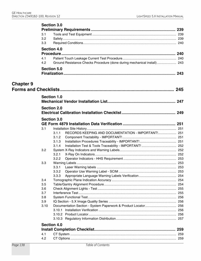
4.2.3 Internal Axial LightsCAUTION LASER EYE INJURY!
NEVER STARE DIRECTLY INTO THE LASER BEAMS WHEN YOU OPERATE THE ALIGNMENT LIGHTS. STARING INTO THE BEAMS CAN CAUSE PERMANENT EYE DAMAGE.
1.) Place a sheet of plain white paper over the output port of each light.
2.) Verify that the two laser lines coincide and appear as a single line.
Note: GE designed the internal axial lasers on the current CT system to shine down on the collimator. Do NOT adjust the internal alignment lights at this time. The tomographic plane tests use the QA phantom to check the internal axial lasers alignment to the collimator.
4.2.4 External Axial to Internal Axial DistanceNote: Ensure that cradle is level.
1.) Raise the table to its highest elevation.
2.) Extend the cradle until you see both the internal and external laser lights shining on the cradle.
3.) Place a metric rule on the right edge of the cradle, and measure the distance from the internal axial laser line to the external axial line. Verify this distance equals 240.0 mm +1.0 mm.
4.) Place the rule on the left edge of the cradle, and measure again.
5.) Leave the cradle in its current position, and lower the table to the minimum elevation.
6.) Measure the distance between the internal and external lights on both edges of the cradle, as above. Verify the distance remains equal to 240.0 mm +1.0 mm.
4.2.5 Coronal Lights
1.) Place a sheet of plain white paper at the left side of the patient opening, in front of the coronal laser light. Verify the two coronal lines coincide.
2.) Move the paper to the right side of the patient opening. Verify the two coronal lines coincide.
3.) Place the paper in the center of the gantry opening. Use a level to verify that the coronal lines are horizontal.
4.2.6 Turn Lights OFFPress the alignment light button on the gantry control panel, again, to turn the lights OFF.

GE HEALTHCAREDIRECTION 2349182-100, REVISION 12 LIGHTSPEED 5.X INSTALLATION MANUAL
Chapter 5 - Electrical Integration and Safety Verifications Page 167
5 –
Inte
g. &
Saf
ety
4.3 Autovoice/Intercom Check
Figure 5-20 SCIM Volume Controls
4.3.1 RequirementsTwo people are required to complete this procedure.
4.3.2 Patient Speaker
1.) To adjust the volume of the patient speaker in the table, adjust the left-most volume thumb wheel on the SCIM while speaking into the console microphone. (Press the bar on the SCIM to talk; release the bar to listen.)
2.) The patient should be able to clearly hear the operator.
4.3.3 Operator Console SpeakerTo adjust the console speaker volume:
1.) Have an assistant speak into the gantry microphone.
2.) Adjust the SCIM console volume knob until you can clearly hear the patient.
4.3.4 Autovoice Volume
1.) On the Scan Desktop, select PROTOCOL MANAGEMENT.
2.) Select AUTO VOICE RECORD.
3.) Click the 3.4 button, to the right of “FF2. Inspiration”.
4.) Click the PLAY button, to play the Inspiration AutoVoice message.
5.) Adjust the center volume thumb wheel while Autovoice is playing, to set the volume for the gantry speaker.
6.) Repeat steps 4 and 5 as necessary to achieve satisfactory volume.
7.) Select DONE, then select QUIT.
Note: If a satisfactory volume can not be achieved, refer to the system service manual and review the intercom module setup procedure.
VolumePatient Speaker
VolumeAutoVoice
VolumeConsole SpeakerPress to talk

GE HEALTHCAREDIRECTION 2349182-100, REVISION 12 LIGHTSPEED 5.X INSTALLATION MANUAL
Page 168 Section 4.0 - Table Gantry Integration
4.4 CT System X-Ray ON Indicators, Cautions & Warning Labels
4.4.1 Check And Install System Warning LabelsAll labels are installed in English and present on PDU, Console, Table, Gantry and Accessories. Replace the labels listed below (Section 4.4.2 through Section 4.4.7) with the appropriate language labels for the country installed. Additionally, apply any other warning labels if present, on equipment where appropriate.
4.4.2 Console
4.4.2.1 On The SCIM• Replace with the appropriate language overlay
• Replace with the appropriate language X-Ray warning label
4.4.2.2 On The Keyboard• Replace with the appropriate language keyboard warning label
• Replace with appropriate language function key overlay label
• Replace with the appropriate language keyboard back warning label
4.4.3 Gantry
4.4.3.1 Scan Window Laser LabelsReplace with the appropriate language laser warning labels
4.4.3.2 Laser Window LabelsReplace with the appropriate language laser warning labels
4.4.3.3 Front Cover Laser WarningReplace with the appropriate language laser warning labels
4.4.3.4 Front cover Information LabelsReplace with the appropriate language labels
4.4.3.5 Gantry System GIB (Rating) labelReplace with the appropriate language system GIB label
4.4.4 Table - 2000mm
4.4.4.1 Front Side Cover - Pinch Hazard Warning LabelReplace with the appropriate language caution label to each side of the cover
4.4.4.2 Back Cradle Pan - Pinch Hazard Warning LabelReplace with the appropriate language caution label to each side of the cover

GE HEALTHCAREDIRECTION 2349182-100, REVISION 12 LIGHTSPEED 5.X INSTALLATION MANUAL
Chapter 5 - Electrical Integration and Safety Verifications Page 169
5 –
Inte
g. &
Saf
ety
4.4.5 Table - 1700mm
4.4.5.1 Front Side Cover - Pinch Hazard Warning LabelReplace with the appropriate language caution label to each side of the cover
4.4.5.2 Rear Side Cover - Pinch Hazard Warning LabelReplace with the appropriate language caution label to each side of the cover
4.4.5.3 Back Cradle Pan - Pinch Hazard Warning Label Replace with the appropriate language caution label to each side of the cover
4.4.6 NGPDU
4.4.6.1 Front Cover - Emergency Off labelReplace with the appropriate language caution label
4.4.6.2 Front Cover - Gantry Enable LabelReplace with the appropriate language caution label
4.4.6.3 Front Cover - Power On Label Replace with the appropriate language caution label
4.4.7 Accessories
4.4.7.1 Table Foot Extender LabelReplace with the appropriate language warning label
4.4.7.2 Coronal Head Holder LabelReplace with the appropriate language warning label
4.4.7.3 Sagittal Head Holder LabelReplace with the appropriate language warning label
4.4.7.4 Accessory Tray LabelReplace with the appropriate language warning label
4.4.7.5 IV Pole LabelReplace with the appropriate language caution label
4.4.8 Documentation - VerificationWhen finished update GE4879 (US Only) and the installation completion form that all appropriate language labels were installed and present.

GE HEALTHCAREDIRECTION 2349182-100, REVISION 12 LIGHTSPEED 5.X INSTALLATION MANUAL
Page 170 Section 4.0 - Table Gantry Integration
4.5 Check Warning Labels
4.5.1 On SCIM
1.) Make sure the X-Ray warning label appears in the correct location on the SCIM.
2.) Record this information on Form 4879 located in Chapter 9 of this book.
4.5.2 On Gantry
1.) Check that all laser warning labels are present on the gantry near the laser opening.
2.) There should also be warning labels on the lower right side of the gantry front cover.
3.) Record this information on Form 4879 located in Chapter 9 of this book.
4.5.3 On Laser
1.) Make sure all laser warning labels appear in the correct location on the outside of the gantry.
2.) Obtain and install replacements for any missing labels.
Figure 5-21 Laser Warnings and Precautions
4.6 Process Product Locator Cards
1.) Collect the product locator cards shipped with the system. There should be approximately 28 product locator cards with the average system.
2.) Update the online product locator web site with the required hospital information.
3.) Confirm that the serial numbers on the cards shipped with the system match those found on the web site for that GON number.
4.) Update as required. Place the cards in a plastic bag, then place them in the service cabinet.
4.7 Install Service Cabinet
The service cabinet is shipped disassembled. The cabinet assembly process takes about 1.5 hours to complete.
1.) Assemble the cabinet following the instructions located in the cabinet’s shipping box.
2.) When completed, place the cabinet in the location shown on the site print.
3.) Place all of the service materials shipped with the system in the service cabinet.
4.8 Check X-Ray Lights
Perform several scans following the steps below. Verify that the X-ray ON lights are ON during the scans. When done, check the boxes in Table 5-2.
1.) Make sure the axial drive enable and HVDC enable switches are ON.
2.) If you are not on the Service Desktop, click on the Service Desktop icon.

GE HEALTHCAREDIRECTION 2349182-100, REVISION 12 LIGHTSPEED 5.X INSTALLATION MANUAL
Chapter 5 - Electrical Integration and Safety Verifications Page 171
5 –
Inte
g. &
Saf
ety
3.) Select DIAGNOSTICS.
4.) Select DIAGNOSTIC DATA COLLECTION.
5.) Set the scan time to 2.00.
6.) Set the kV to 80.
7.) Set the mA to 40.
8.) Press ACCEPT RX.
9.) Press START SCAN button when flashing.
10.) Record the above information on Form 4879 located in Chapter 9 of this book.
4.9 Mechanical Characterization
The relationship of table height to ISO center and internal-to-external landmarks must be characterized for proper interference matrix functionality.
Note: Do NOT perform tilt characterization.
4.9.1 Alignment Light Characterization
1.) Start the Mechanical Characterization tool from the Calibration tab on the Common Service Desktop.
2.) Select the CHARACTERIZE ALIGNMENT LIGHTS button from the interface.
3.) Follow the on-screen instructions.
4.9.2 Alignment Light Characterization
1.) Select the CHARACTERIZE TABLE HEIGHT button from the interface.
2.) Follow the on-screen instructions.
Note: If the table height is less than 21mm or greater than 25mm, relative to ISO, you must adjust the table height using the table leveling pad and adjusters. Raise or lower all four adjusters equally to achieve desired results.
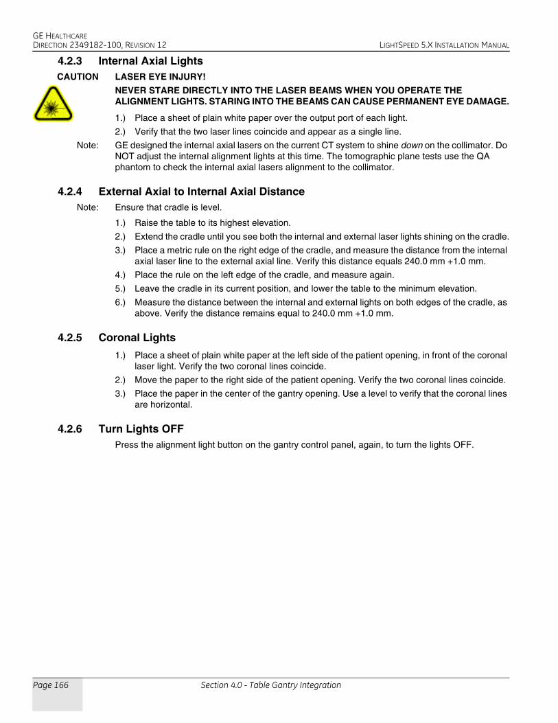
4.10 Interference Test
PREREQUISITES• Be sure that the System State was restored from DVD per Section 2.0.
• Reset the hardware to download the new characterization values before performing the table/gantry interference tests in this section.
Light On? Warning Light Locations
SCIM
Gantry Front
Gantry Back (Use a mirror to view)
Room Light (outside of the room)
Table 5-2 X-ray Light Chart
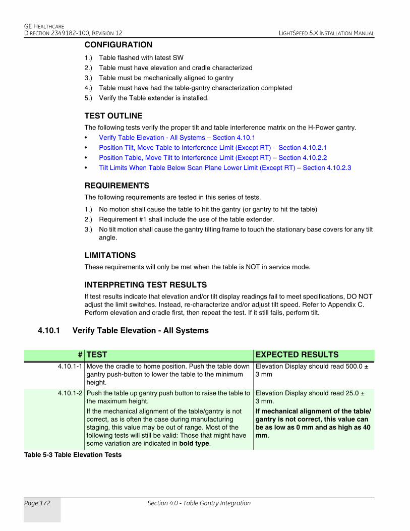
GE HEALTHCAREDIRECTION 2349182-100, REVISION 12 LIGHTSPEED 5.X INSTALLATION MANUAL
Page 172 Section 4.0 - Table Gantry Integration
CONFIGURATION
1.) Table flashed with latest SW
2.) Table must have elevation and cradle characterized
3.) Table must be mechanically aligned to gantry
4.) Table must have had the table-gantry characterization completed
5.) Verify the Table extender is installed.
TEST OUTLINEThe following tests verify the proper tilt and table interference matrix on the H-Power gantry.
• Verify Table Elevation - All Systems – Section 4.10.1
• Position Tilt, Move Table to Interference Limit (Except RT) – Section 4.10.2.1
• Position Table, Move Tilt to Interference Limit (Except RT) – Section 4.10.2.2
• Tilt Limits When Table Below Scan Plane Lower Limit (Except RT) – Section 4.10.2.3
REQUIREMENTSThe following requirements are tested in this series of tests.
1.) No motion shall cause the table to hit the gantry (or gantry to hit the table)
2.) Requirement #1 shall include the use of the table extender.
3.) No tilt motion shall cause the gantry tilting frame to touch the stationary base covers for any tilt angle.
LIMITATIONSThese requirements will only be met when the table is NOT in service mode.
INTERPRETING TEST RESULTSIf test results indicate that elevation and/or tilt display readings fail to meet specifications, DO NOT adjust the limit switches. Instead, re-characterize and/or adjust tilt speed. Refer to Appendix C. Perform elevation and cradle first, then repeat the test. If it still fails, perform tilt.
4.10.1 Verify Table Elevation - All Systems
# TEST EXPECTED RESULTS 4.10.1-1 Move the cradle to home position. Push the table down
gantry push-button to lower the table to the minimum height.
Elevation Display should read 500.0 ± 3 mm
4.10.1-2 Push the table up gantry push button to raise the table to the maximum height.
If the mechanical alignment of the table/gantry is not correct, as is often the case during manufacturing staging, this value may be out of range. Most of the following tests will still be valid: Those that might have some variation are indicated in bold type.
Elevation Display should read 25.0 ± 3 mm.
If mechanical alignment of the table/gantry is not correct, this value can be as low as 0 mm and as high as 40 mm.
Table 5-3 Table Elevation Tests

GE HEALTHCAREDIRECTION 2349182-100, REVISION 12 LIGHTSPEED 5.X INSTALLATION MANUAL
Chapter 5 - Electrical Integration and Safety Verifications Page 173
5 –
Inte
g. &
Saf
ety
4.10.2 Tests for Pro16, LS16, Ultra & Plus Systems
4.10.2.1 Position Tilt, Move Table to Interference Limit (Except RT)The following tests verify the table interference limits at different tilt locations.
Note: • “I” means top of gantry tilts toward the table base
• “S” means top of gantry tilts away from the table base.
Note: For all tests, make sure there is 2.5 cm of clearance between the gantry and table. Also make sure that the Gantry Tilting frame covers do not touch the stationary base covers, for all tilt angles used in this test.
# TEST EXPECTED RESULTS4.10.2.1-1 Move cradle to home position and set
internal landmark.Cradle position on display should read 0.0
4.10.2.1-2 Raise table height to maximum height, set the internal landmark, move cradle into gantry 1000.0mm.
Table elevation on display should read 25.0 ± 3mm. (This value will be the same as in 4.10.1-2 above.) Cradle position on display should read 1000.0mm.
4.10.2.1-3 Tilt the gantry to I30.0, then lower table until motion stops.
Table elevation on display should read 100 ± 3mm. Tilt display should read I30.
4.10.2.1-4 Tilt the gantry to I23.0, then lower table until motion stops.
Table elevation on display should read 155 ± 3mm. Tilt display should read I23.
4.10.2.1-5 Tilt the gantry to I20.0, then lower table until motion stops.
Table elevation on display should read 170 ± 3mm. Tilt display should read I20.
4.10.2.1-6 Raise the table elevation to maximum height.
Table elevation on display should read 25.0 ± 3mm. (This value will be the same as in 4.10.1-2 above.)
4.10.2.1-7 Tilt the gantry to S30.0, then lower table until motion stops.
Table elevation on display should read 156 ± 3mm. Tilt display should read S30.
4.10.2.1-8 Tilt the gantry to S23.0, then lower table until motion stops.
Table elevation on display should read 182 ± 3mm. Tilt display should read S23.
4.10.2.1-9 Tilt the gantry to S20.0, then lower table until motion stops.
Table elevation on display should read 192 ± 3mm. Tilt display should read S20.
4.10.2.1-10 Raise the table to 154 mm. Table elevation on display should read 154mm.
4.10.2.1-11 Tilt gantry to S30 and verify the table height can be adjusted from 154 to 25 mm. (This value will be the same as in 4.10.1-2 above.)
Tilt display should read S30. Table lower limit should be 154 ± 3mm. Upper table limit should be 25 ± 3 mm. (This value will be the same as in 4.10.1-2 above.)
4.10.2.1-12 Set the table height to 98 mm. Table elevation on display should read 98mm.
4.10.2.1-13 Tilt gantry to I30 and verify the table height can be adjusted from 98 to 25 mm. (This value will be the same as in 4.10.1-2 above.)
Tilt display should read I30. Table lower limit should be 98 ± 3mm. Upper table limit should be 25 ± 3 mm. (This value will be the same as in 4.10.1-2 above)
Table 5-4 Position Tilt, Move Table to Interference Limit Tests (Pro16, LS16, Ultra & Plus)

GE HEALTHCAREDIRECTION 2349182-100, REVISION 12 LIGHTSPEED 5.X INSTALLATION MANUAL
Page 174 Section 4.0 - Table Gantry Integration
4.10.2.2 Position Table, Move Tilt to Interference Limit (Except RT)The following tests verify the tilt interference limits at different table heights.
Note: • “I” means top of gantry tilts toward the table base
• “S” means top of gantry tilts away from the table base.
Note: For all tests, make sure there is 2.5 cm of clearance between the gantry and table.
4.10.2.3 Tilt Limits When Table Below Scan Plane Lower Limit (Except RT)The following tests verify the table and tilt interference limits when the table height is below the scan plane.
Note: • “I” means top of gantry tilts toward the table base
• “S” means top of gantry tilts away from the table base.
Note: For all tests, make sure there is 2.5 cm of clearance between the gantry and table.
# TEST EXPECTED RESULTS4.10.2.2-1 Move cradle to home position and set
internal landmark. Set gantry tilt to zero.Cradle position on display should read 0.0.Gantry tilt on display should read 0.0.
4.10.2.2-2 Raise table height to maximum height, set the internal landmark, move cradle into gantry 1m.
Table elevation on display should read 25.0 ± 3mm. (This value will be the same as in 4.10.1-2 above.) Cradle position on display should read 1000.0 mm.
4.10.2.2-3 Lower table until height is 115mm. Tilt the gantry top away from the table (“S”) until it stops.
Table elevation on display should read 115 mm. Tilt display should read S30 ±0.5º.
4.10.2.2-4 Tilt the gantry top toward the table (“I”) until it stops.
Table elevation on display should read 115 mm. Tilt display should read I28 ±0.5º.
4.10.2.2-5 Tilt the gantry to 0. Lower table until height is 200mm. Tilt the gantry top away from the table (“S”) until it stops.
Table elevation on display should read 200 mm. Tilt display should read S17 ±0.5º.
4.10.2.2-6 Tilt the gantry top toward the table (“I”) until it stops.
Table elevation on display should read 200 mm. Tilt display should read I14.5 ±0.5º.
4.10.2.2-7 Tilt the gantry to 0. Lower table until height is 210 mm. Tilt the gantry top away from the table (“S”) until it stops.
Table elevation on display should read 210 mm. Tilt display should read S13.5 ±0.5º.
4.10.2.2-8 Tilt the gantry top toward the table (“I”) until it stops.
Table elevation on display should read 210 mm. Tilt display should read I12 ±0.5º.
Table 5-5 Position Table, Move Tilt to Interference Limit Tests (Pro16, LS16, Ultra & Plus)
# TEST EXPECTED RESULTS4.10.2.3-1 Set gantry tilt to zero. Move cradle to
home position, lower the table all the way, and set the internal landmark.
Cradle position on display should read 0.0 Gantry tilt on display should read 0.0. Table height should read 500 ± 3 mm. (This value will be the offset from 500 mm by the same amount as the upper table limit varies from 25 mm in 4.10.1-2 above.)
4.10.2.3-2 Tilt the gantry forward and backwards and verify the following tilt limits: S4.0 and I30.
Gantry tilt on display should read S4.0 ± 0.5º. Gantry tilt on display should read I30.0 ± 0.5º.
Table 5-6 Tilt Limits When Table Below Scan Plane Lower Limit Tests (Pro16, LS16, Ultra & Plus)

GE HEALTHCAREDIRECTION 2349182-100, REVISION 12 LIGHTSPEED 5.X INSTALLATION MANUAL
Chapter 5 - Electrical Integration and Safety Verifications Page 175
5 –
Inte
g. &
Saf
ety
4.10.2.3-3 Set Gantry tilt to 0. Then, using the gantry push-buttons, move the cradle in towards the gantry until it is stopped.
Gantry tilt on display should read 0.0. Cradle should stop at 58.5 mm ± 6 mm from the home position. (This value will not be valid if the table/gantry mechanical characterization is not correct as described in 4.10.1-2 above. Insure that the front of the table is at least 25 mm from the gantry.)
4.10.2.3-4 Set gantry tilt to zero. Move cradle to home position.
Cradle position on display should read 0.0 Gantry tilt on display should read 0.0.
4.10.2.3-5 Raise the table to a height of 386 mm and verify the following tilt limits: S7.0 and I30.0.
Table height should read 386 mm. Gantry tilt on display should read S7.0 ± 0.5º. Gantry tilt on display should read I30.0 ± 0.5º.
4.10.2.3-6 Set Gantry tilt to 0. Set the internal landmark. Then, using the gantry push-buttons, move the cradle in towards the gantry until it is stopped.
Gantry tilt on display should read 0.0. Cradle should stop at 91 mm ± 6 mm from the home position.
4.10.2.3-7 Set gantry tilt to zero. Move cradle to home position.
Cradle position on display should read 0.0. Gantry tilt on display should read 0.0.
4.10.2.3-8 Raise the table to a height of 242 mm and verify the following tilt limits: S12.0 and I30.0.
Table height should read 242 mm. Gantry tilt on display should read S12.0 ± 0.5º. Gantry tilt on display should read I30.0 ± 0.5º.
4.10.2.3-9 Set Gantry tilt to 0. Raise the table to 210 mm. Then, using the gantry push-buttons, move the cradle in towards the gantry until it is stopped.
Gantry tilt on display should read 0.0. Cradle should go all the way through the gantry bore to the full-extended position.
4.10.2.3-10 Set gantry tilt to zero. Move cradle to home position, lower the table all the way and set the internal landmark.
Cradle position on display should read 0.0 Gantry tilt on display should read 0.0. Table height should read 500 ± 3 mm. (This value will be the offset from 500 mm by the same amount as the upper table limit varies from 25 mm in 4.10.1-2 above.)
4.10.2.3-11 Tilt the gantry top toward the table to a tilt of 30 degrees
Display should read I30.
4.10.2.3-12 With the table down all the way, move the cradle in until it stops.
Cradle position should be 377.3 ±3 mm.
4.10.2.3-13 Move the table to the home position, raise the table to a height of 386 mm, set the internal landmark, and then move the cradle in until it stops.
Cradle position should be 350 ±50 mm.
4.10.2.3-14 Raise the table to a height of 100 mm, then move the cradle in.
Cradle should go all the way through the gantry bore to the full-extended position.
# TEST EXPECTED RESULTS
Table 5-6 Tilt Limits When Table Below Scan Plane Lower Limit Tests (Pro16, LS16, Ultra & Plus) (Continued)

GE HEALTHCAREDIRECTION 2349182-100, REVISION 12 LIGHTSPEED 5.X INSTALLATION MANUAL
Page 176 Section 4.0 - Table Gantry Integration
4.10.3 Tests for RT Systems Only
4.10.3.1 Position Tilt, Move Table to Interference Limit (RT)The following tests verify the table interference limits at different tilt locations.
Note: • “I” means top of gantry tilts toward the table base
• “S” means top of gantry tilts away from the table base.
Note: For all tests, make sure there is 2.5 cm of clearance between the gantry and table. Also make sure that the Gantry Tilting frame covers do not touch the stationary base covers, for all tilt angles used in this test.
# TEST EXPECTED RESULTS4.10.2.1-1 Move cradle to home position and set
internal landmark.Cradle position on display should read 0.0
4.10.2.1-2 a) Raise table height to maximum height, b) Set the internal landmark, c) Move cradle into gantry 1m.
a) Table elevation on display should read 25.0 ± 3mm. (This value will be the same as in 4.10.1-2 above.)b) Cradle position on display should read 0.0 mmc) Cradle position on display should read 1000.0 mm.
4.10.2.1-3 a) Tilt the gantry to I30.0, b) Then lower table until motion stops.
a) Tilt display should read I30.b) Table elevation on display should read 90 ± 3mm.
4.10.2.1-4 a) Tilt the gantry to I23.0, b) Then lower table until motion stops.
a) Tilt display should read I23.b) Table elevation on display should read 166.5 ± 3mm.
4.10.2.1-5 a) Tilt the gantry to I20.0, b) Then lower table until motion stops.
a) Tilt display should read I20.b) Table elevation on display should read 189.5 ± 3mm.
4.10.2.1-6 Raise the table elevation to maximum height.
Table elevation on display should read 25.0 ± 3mm. (This value will be the same as in 4.10.1-2 above.)
4.10.2.1-7 a) Tilt the gantry to S30.0, b) Then lower table until motion stops.
a) Tilt display should read S30.b) Table elevation on display should read 189.5 ± 3mm.
4.10.2.1-8 a) Tilt the gantry to S23.0, b) Then lower table until motion stops.
a) Tilt display should read S23.b) Table elevation on display should read 220 ± 3mm.
4.10.2.1-9 a) Tilt the gantry to S20.0, b) Then lower table until motion stops.
a) Tilt display should read S20.b) Table elevation on display should read 233 ± 3mm.
4.10.2.1-10 Raise the table to 187 mm. Table elevation on display should read 187.0mm
4.10.2.1-11 a) Tilt gantry to S30 and b) Verify the table height can be adjusted from 189 to 25 mm. (This value will be the same as in 4.10.1-2 above.)
a) Tilt display should read S30. b) Table lower limit should be 189.5 ± 3mm. Upper table limit should be 25 ± 3 mm. (This value will be the same as in 4.10.1-2 above.)
4.10.2.1-13 a) Tilt gantry to I30 and b) Verify the table height can be adjusted from 25 mm (This value will be the same as in 4.10.1-2 above) to 90 mm.
a) Tilt display should read I30. b) Upper table limit should be 25 ± 3 mm. (This value will be the same as in 4.10.1-2 above) Table lower limit should be 90 ± 3mm.
Table 5-7 Position Tilt, Move Table to Interference Limit Tests (RT)

GE HEALTHCAREDIRECTION 2349182-100, REVISION 12 LIGHTSPEED 5.X INSTALLATION MANUAL
Chapter 5 - Electrical Integration and Safety Verifications Page 177
5 –
Inte
g. &
Saf
ety
4.10.3.2 Position Table, Move Tilt to Interference Limit (RT)The following tests verify the tilt interference limits at different table heights.
Note: • “I” means top of gantry tilts toward the table base
• “S” means top of gantry tilts away from the table base.
Note: For all tests, make sure there is 2.5 cm of clearance between the gantry and table.
4.10.3.3 Tilt Limits When Table Below Scan Plane Lower Limit (RT)The following tests verify the table and tilt interference limits when the table height is below the scan plane.
Note: • “I” means top of gantry tilts toward the table base
• “S” means top of gantry tilts away from the table base.
Note: For all tests, make sure there is 2.5 cm of clearance between the gantry and table.
# TEST EXPECTED RESULTS4.10.2.2-1 a) Move cradle to home position and set
internal landmark. b) Set gantry tilt to zero.
a) Cradle position on display should read 0.0.b) Gantry tilt on display should read 0.0.
4.10.2.2-2 a) Raise table height to maximum height, b) Set the internal landmark, c) Move cradle into gantry 1000mm.
a) Table elevation on display should read 25.0 ± 3mm. (This value will be the same as in 4.10.1-2 above.)b) Cradle position on display should read 0.0 mm.c) Cradle position on display should read 1000.0 mm.
4.10.2.2-3 a) Lower table until height is 115mm.b) Tilt the gantry top away from the table (“S”) until it stops.
a) Table elevation on display should read 115 mm. b) Tilt display should read S30 ±0.5º.
4.10.2.2-4 Tilt the gantry top toward the table (“I”) until it stops.
Table elevation on display should read 115 mm. Tilt display should read I27.5 ±0.5º.
4.10.2.2-5 a) Tilt the gantry to 0. b) Lower table until height is 200mm.c) Tilt the gantry top away from the table (“S”) until it stops.
a) Tilt display should read 0.0b) Table elevation on display should read 200 mm.c) Tilt display should read S27.5 ±0.5º.
4.10.2.2-6 Tilt the gantry top toward the table (“I”) until it stops.
Table elevation on display should read 200 mm. Tilt display should read I18 ±0.5º.
4.10.2.2-7 a) Tilt the gantry to 0. b) Lower table until height is 288 mm.c) Tilt the gantry top away from the table (“S”) until it stops.
a) Tilt display should read 0.0b) Table elevation on display should read 288 mm. c) Tilt display should read S2.0 ±0.5º.
4.10.2.2-8 Tilt the gantry top toward the table (“I”) until it stops.
Table elevation on display should read 288 mm. Tilt display should read I1.5 ±0.5º.
Table 5-8 Position Table, Move Tilt to Interference Limit Tests (RT)
# TEST EXPECTED RESULTS4.10.2.3-1 a) Set gantry tilt to zero.
b) Move cradle to home position, then lower the table all the way, and
c) Set the internal landmark.
a) Gantry tilt on display should read 0.0b) Table height should read 500 ± 3 mm. (This value will be the offset from 500 mm by the same amount as the upper table limit varies from 25 mm in 4.10.1-2 above.)c) Cradle position on display should read 0.0
Table 5-9 Tilt Limits When Table Below Scan Plane Lower Limit Tests (RT)

GE HEALTHCAREDIRECTION 2349182-100, REVISION 12 LIGHTSPEED 5.X INSTALLATION MANUAL
Page 178 Section 4.0 - Table Gantry Integration
4.10.2.3-2 Tilt the gantry forward and backwards and verify the following tilt limits: I30 and S6.0.
Gantry tilt on display should read I30.0 ± 0.5º.Gantry tilt on display should read S6.0 ± 0.5º.
4.10.2.3-3 a) Set Gantry tilt to 0. b) Using the gantry push-buttons, move the cradle in towards the gantry until it is stopped.
a) Gantry tilt on display should read 0.0. b) Cradle should stop at 89.5 mm ± 6 mm from the home position. (This value will not be valid if the table/gantry mechanical characterization is not correct as described in 4.10.1-2 above. Insure that the front of the table is at least 25 mm from the gantry.)
4.10.2.3-4 a) Set gantry tilt to zero. b) Move cradle to home position.
a) Cradle position on display should read 0.0 b) Gantry tilt on display should read 0.0.
4.10.2.3-5 a) Raise the table to a height of 386 mm b) verify the following tilt limits: S10.0 and I30.0.
a) Table height should read 386 mm. b) Gantry tilt on display should read S10.0 ± 0.5º. Gantry tilt on display should read I30.0 ± 0.5º.
4.10.2.3-6 a) Set Gantry tilt to 0. b) Set the internal landmark. c) Using the gantry pushbuttons, move the cradle in towards the gantry until it is stopped.
a) Gantry tilt on display should read 0.0. b) Cradle display should read 0.0c) Cradle should stop at 114 mm ± 6 mm from the home position.
4.10.2.3-7 a) Set gantry tilt to zero. b) Move cradle to home position.
a) Gantry tilt on display should read 0.0.b) Cradle position on display should read 0.0.
4.10.2.3-8 a) Raise the table to a height of 242 mm b) Verify the following tilt limits: S17.5 and I30.0.
a) Table height should read 242 mm. b) Gantry tilt on display should read S17.5 ± 0.5º. Gantry tilt on display should read I30.0 ± 0.5º.
4.10.2.3-9 a) Set Gantry tilt to zero. b) Raise the table to 210 mm. c) Using the gantry push-buttons, move the cradle in towards the gantry until it is stopped.
a) Gantry tilt on display should read 0.0. b) Table height should read 210mm c) Cradle should go all the way through the gantry bore to the full-extended position. ~1845mm ±10mm
4.10.2.3-10 a) Set gantry tilt to zero. b) Move cradle to home position, then lower the table all the way
c) Set the internal landmark.
a) Gantry tilt on display should read 0.0. b) Table height should read 500 ± 3 mm. (This value will be the offset from 500 mm by the same amount as the upper table limit varies from 25 mm in 4.10.1-2 above.)c) Cradle position on display should read 0.0
4.10.2.3-11 Tilt the gantry top toward the table to a tilt of 30 degrees
Display should read I30.
4.10.2.3-12 With the table down all the way, move the cradle in until it stops.
Cradle position should be 403 ±3 mm.
4.10.2.3-13 a) Move the table to the home position, raise the table to a height of 386 mm,b) Set the internal landmark, c) Then move the cradle in until it stops.
a) Table height should read 386.0mm
b) Cradle position should be 0.0mmc) Cradle position should be 358 ±50 mm.
4.10.2.3-14 Raise the table to a height of 87 mm, then move the cradle in.
Cradle should go all the way through the gantry bore to the full-extended position.
# TEST EXPECTED RESULTS
Table 5-9 Tilt Limits When Table Below Scan Plane Lower Limit Tests (RT)

GE HEALTHCAREDIRECTION 2349182-100, REVISION 12 LIGHTSPEED 5.X INSTALLATION MANUAL
Chapter 5 - Electrical Integration and Safety Verifications Page 179
5 –
Inte
g. &
Saf
ety
4.10.3.4 Gantry Rotational Characterization (RT Systems Only)For RT systems, this characterization is required on installation and when any axial drive components are changed.
Refer to the Gantry Rotational Characterization procedure on the Service CD for the instructions.
4.10.3.5 Alignment Light Characterization (RT Systems Only)For RT systems, this characterization is only needed if the customer has supplied their own external gantry laser alignment lights. In this instance the gantry external lasers are disabled and the distance from the customer external lasers to the gantry internal lasers must be characterized.
TOOLS/SUPPLIES NEEDED• Cable Ties
• Part 5111615: “Laser not used” labels for laser assemblies (2 per system required)
• Part 5111733: “Laser not used” labels for above the external laser windows on front cover (2 per system required)
Note: Both labels can be found in the installation support kit.
PROCEDURE
1.) Remove right side gantry cover.
DANGER CRUSH HAZARD.UNEXPECTED GANTRY ROTATION CAN CAUSE SERIOUS INJURY.NEVER SERVICE THE GANTRY WITH THE AXIAL DRIVE ENABLED.
2.) Turn OFF the Axial Drive on the service switch panel.
3.) For external laser light near the 107 degree weight stack:
a.) Rotate gantry by hand until the laser bracket nearest the 107deg weight stack is accessible. Figure 5-22 below shows the two external laser light brackets with the front cover off for reference.
Figure 5-22 Two External Lasers
Figure 5-23 Laser bracket near 107 degree weight stack
Laser Power Connector

GE HEALTHCAREDIRECTION 2349182-100, REVISION 12 LIGHTSPEED 5.X INSTALLATION MANUAL
Page 180 Section 4.0 - Table Gantry Integration
WARNING POTENTIAL FOR SHOCKVOLTAGE MAY BE PRESENT.ENSURE LASERS ARE TURNED OFF, PRIOR TO DISCONNECTING THEM.
b.) Turn OFF the 120VAC enable switch on the service switch panel.
c.) Disconnect laser power plug. Cut the cable ties that hold the cable and plug in place if needed for better access.
d.) Wrap additional cable on the laser diode side around the laser holder and secure the female plug with cable tie(s).
e.) Secure the male end of the plug to the external laser bracket with cable ties as required.
Note: Be sure to secure the plugs adequately to prevent movement during gantry rotation.
f.) Be sure to re-secure any loose cable where cable ties may have been removed for better access.
g.) Place label Part #5111615 on the cable to the laser diode.
h.) Rotate gantry (if needed for access) towards the external laser located near the heat exchanger and repeat Step b through Step f. Turn ON the 120VAC to rotate the gantry easier and then turn it back OFF prior to continuing.
Figure 5-24 Laser bracket near Heat Exchanger
4.) Enable 120AC and Axial Drive.
5.) Replace right side gantry cover and secure.
6.) Place labels 5111733 on the front gantry cover near the gantry external laser ports. See Figure 5-25, below.
Figure 5-25 External Laser Ports - Label Locations
7.) Perform the Gantry Alignment light characterization procedure to characterize the distance from the customer external lasers to the gantry internal lasers.
Laser Power Connector
Label Locations

GE HEALTHCAREDIRECTION 2349182-100, REVISION 12 LIGHTSPEED 5.X INSTALLATION MANUAL
Chapter 5 - Electrical Integration and Safety Verifications Page 181
5 –
Inte
g. &
Saf
ety
4.10.4 Alignment Light Characterization - All Systems
4.10.4.1 OverviewThe “Characterize Alignment Lights” is part of the Mechanical Characterization tool available under the Calibration tab on the Common Service Desktop. This tool gives the ability to characterize the distance between the internal and external laser alignment lights. Typically this is used to characterize the distance from the gantry external laser lights to the internal laser lights, which is typically 240mm. For some systems, the customer will supply a set of wall mount laser alignment lights that can provide an external alignment location up to 650mm from the gantry internal laser alignment lights. In this instance the gantry external laser lights are physically disconnected and not used and the characterization is performed from the customer supplied alignment lights to the gantry internal lasers.
4.10.4.2 Procedure
1.) Start the Mechanical Characterization tool from the Calibration tab on the Common Service Desktop.
2.) Select the “Characterize Alignment Lights” button from the interface.
3.) Follow the on-screen instructions.
Pay attention to the table height instructions that depend on what system you are characterizing.
Table height for Gantry laser characterization is different from the table height needed to characterize a customer supplied laser alignment system. This is due to the table travel distance needed to position the black alignment dot on the cradle at the customer alignment light and still drive into the bore without hitting the gantry.

GE HEALTHCAREDIRECTION 2349182-100, REVISION 12 LIGHTSPEED 5.X INSTALLATION MANUAL
Page 182 Section 4.0 - Table Gantry Integration
End of Chapter.

GE HEALTHCAREDIRECTION 2349182-100, REVISION 12 LIGHTSPEED 5.X INSTALLATION MANUAL
Chapter 6 - Image Quality Page 183
6 –
Imag
e Q
ualit
y
Chapter 6Image Quality
NOTICE To prevent potential data loss, please do the following:
• Record data collected from procedures in this chapter into Form F4879 when directed, located in Chapter 9 of this book.
• Only use the Installation manual that arrives with your system for installation. Any other revisions of this manual may not exactly match your system.
Section 1.0Introduction
Figure 6-1 System Test Overview
End
Table Gantry
Image Series
Save System State
Start
Tube Warmup & Fast Cal
Calibration Process
Tomographic Plane Indication
System Functional Test

GE HEALTHCAREDIRECTION 2349182-100, REVISION 12 LIGHTSPEED 5.X INSTALLATION MANUAL
Page 184 Section 2.0 - Calibration Process
Section 2.0Calibration Process
2.1 Reference Procedures
Do not perform these procedures (“Scanning with Service Protocols” or “Center Phantom”) until instructed to do so in other sections of this chapter.
2.1.1 Scanning with Service ProtocolsLocate the Manufacturing and Installation protocols under Infant area 20.
Note: Manufacturing and Service share this Protocol list. Different product option offerings also use this list. Carefully follow the scan section instructions, and verify you acquired the images with the correct technique before filling out the data sheet. Otherwise you may troubleshoot an image problem that only exists because you used the wrong technique.
1.) Select the NEW PATIENT icon on the left monitor
2.) Enter a Patient ID (e.g., getest).3.) Click on the box labeled PEDIATRIC.
4.) Select a service protocol from the list, to display the corresponding view edit screen.
Optional Method: Enter the protocol number into the Protocol Number Field on the Exam Rx Screen.
2.1.2 Center Phantom
1.) Select SCANNER UTILITIES icon on the left monitor
2.) Select CENTER PHANTOM.
3.) Follow the on-screen procedures.
4.) The phantom center spec is ±.5mm.
5.) Select QUIT, when the phantom is within specification.
6.) Level the phantom both front to back and side to side. (use a 6" level)
2.2 Prepare the QA Phantom
Note: The QA phantom is shipped water filled.
1.) Locate the multi-language sticker packet in the QA phantom shipping box.
2.) Attach the sticker with the customer's language to the face of the phantom hanger bracket.
2.3 Calibration Process Introduction
If your system has a factory supplied state MOD, you used it to load the system calibration files during the Restore System State (2.3 on page 152 of this manual).

GE HEALTHCAREDIRECTION 2349182-100, REVISION 12 LIGHTSPEED 5.X INSTALLATION MANUAL
Chapter 6 - Image Quality Page 185
6 –
Imag
e Q
ualit
y
Section 3.0Table/Gantry Alignment Procedure
3.1 Conditions
This procedure may require the removal of the table bottom, side and rail covers.
This procedure requires that mechanical final alignment was completed and passed.
3.2 Procedure
1.) If this is a Non-Fixed Site, check the Van level. Correct, if necessary.
2.) Check Table level. Correct, if necessary.
3.) Drive the table to its highest elevation (phantom holder removed).
4.) Drive the table cradle in and out five times to seat the rollers.
5.) Turn on the alignment lights. Check the scan window for proper installation.
6.) Advance the end of the cradle (black dot on cradle) to the internal light.
7.) Complete Section 2.1.1, “Scanning with Service Protocols” now.
8.) Select the service protocol PERPENDICULAR ALIGNMENT. Protocol should appear as shown in Table 6-1.
Set Internal Landmark. The red boxes will disappear from the screen.
9.) Click on CONFIRM, then press the START SCAN button when lighted, to perform the scan.
10.) Use over/under multi-image display to view both images at the same time:
a.) Click on IMAGE WORKS
b.) Highlight the scans just performed and click on VIEWER.
c.) Click on FORMAT, and select the “over/under” view (two boxes aligned vertically).
11.) Use the upper image (cradle front) to verify that table is centered:
a.) Click on the “grid” icon.
b.) Click on MEASURE, and select the straight (angled) line.
c.) Using the mouse, position one end of the line on the vertical axis.
d.) Position the other end at one outside edge of the cradle, forming a perfectly horizontal line (angle = 90). Read the distance displayed on screen.
e.) Repeat step d to measure the distance from the vertical axis to the other edge.
12.) Repeat step 11 for the lower image (cradle at 1000 mm).
Scan Type
Direction kV mA SFOV Thickness Scan Time
Start Loc.
End Loc.
Algorithm
Axial Head First 120 40 Large 5mm/1i 2sec S0 S0 Bone
Axial Head First 120 40 Large 5mm/1i 2sec I1000 I1000 Bone
Scout 120 40 90o S0 I1000
Scout 120 40 0o S0 I1000
Table 6-1 Perpendicular Alignment Scan Parameters

GE HEALTHCAREDIRECTION 2349182-100, REVISION 12 LIGHTSPEED 5.X INSTALLATION MANUAL
Page 186 Section 4.0 - Tube Warm Up and Fast Cal
13.) If the edges are off by greater than 1 mm (front to back), perform the following:
a.) Loosen the table anchors at locations #5, #6 and #7.
b.) Move the table half the measured distance.
c.) Return to Step 8. Repeat the procedure until the table edges line up (± 1mm). If needed a scout can be completed to check table horizontal presentation
Check the two scout scans
i.) Check the tube at zero scan for table gantry perpendicularity. Make table adjustments as needed
ii.) Check the tube at 90 scan for cradle level and visual irregularity with the white side molding. Molding strips should be parallel within +/- 3 mm. Cradle should be level within ± 3 mm.
d.) Tighten the anchors and torque to 74.6 N-m (55 ft.-lb.) for fixed sites only. (75 ft-lb.) for non-fixed systems.
e.) Reinstall all table parts removed to access the anchors, including covers, ground straps, elevation motor leads and the center support bar.
14.) Install all table and gantry covers.
15.) Use ERASE ALL to remove lines and grids from the images.
16.) Click on END EXAM to exit the program.
Section 4.0Tube Warm Up and Fast Cal
1.) Select DAILY PREP, to warm up the tube.
2.) Select FAST CALIBRATION from the Daily Prep menu.
Note: Use the default Fast Cal selections determined by the system configuration. (The system defaults to all four kV stations, but you can choose kV stations to calibrate during reconfig.)
3.) Run the selected air calibrations.
4.) When the calibration process completes, click on QUIT.

GE HEALTHCAREDIRECTION 2349182-100, REVISION 12 LIGHTSPEED 5.X INSTALLATION MANUAL
Chapter 6 - Image Quality Page 187
6 –
Imag
e Q
ualit
y
Section 5.0Tomographic Plane Indication
1.) Place the QA phantom on the phantom holder.
2.) Center the Phantom (refer to procedure 2.1.2 on page 184)
3.) Turn ON the internal alignment lights, and drive the phantom into the gantry opening, until the line on the phantom lines up with the internal laser lights.
4.) Verify that BOTH internal axial lasers line up along the line on the QA phantom. If not, check table/gantry, cradle, and/or laser alignment.
5.) Center the phantom in the scan plane with the calibration program. (See 2.1.2 on page 184 for details on the phantom centering procedure.)
6.) Select the service protocol TOMO PLANE INDICATION. (See 2.1.1 on page 184 for details on scanning with service protocols.)
or
Manually select the scan parameters in Table 6-2.
7.) Display the image series, and locate the scan plane indicator, the longest bar in the bar pattern on the right side of the phantom. The right side of the phantom corresponds to the side of the image labeled L on the display screen.
8.) On the HHS Data Sheet, record the scan location (shown on the image annotation) of the image with the darkest scan plane indicator (darkest long bar).
9.) If your system meets all the installation and alignment specifications, the image at scan location zero (S0.0) should contain the scan plane indicator. If scan location S1.0 or scan location I1.0 has the darkest bar, the system still meets the specification. The scan plane deviation should equal S0.0 +1.0mm. If necessary, adjust the internal alignment light position to meet the S0.0 +1.0mm requirement.
10.) Repeat the Tomographic Plane Indication test with the external alignment lights.
a.) Use the external alignment light, and press the external landmark.
b.) Verify the external light lines up along the black line on BOTH the left and right sides of the QA phantom.
c.) The scan plane indication must fall within the S0.0 +1.0mm specification.
11.) Initial below.
________________
Scan Type
kV mA SFOV Thickness Scan Time
Start Loc.
End Loc.
Algorithm Interval
Helical 120 200 Small 1.25HQ 1.0sec I3.0 S3.0 Bone detail 0.2
Table 6-2 Tomographic Plane Indication Scan Parameters

GE HEALTHCAREDIRECTION 2349182-100, REVISION 12 LIGHTSPEED 5.X INSTALLATION MANUAL
Page 188 Section 6.0 - Image Series
Section 6.0Image Series
IMPORTANT: Run ALL Image Series Tests in Auto Mode. Manual procedures are provided in this section as REFERENCE ONLY.
6.1 Scan Protocol
The person who acquires the image series has the responsibility to review the images and verify they meet the specifications listed on data sheets. Responsibilities also include means and stan-dard deviation measurements and keeping a record of failures that occur during the image series.
Unless otherwise stated, use the following scan parameters during the image series acquisition:
• Scan FOV equal to display FOV (Field of View)
• 512x512 matrix size
Note: Consider any image series scan that does not meet specifications as failing.
For means and standard deviations, 90% of the slices must pass. Any failure on a particular technique requires at least ten additional slices to evaluate effectively.
Systems with metal-free cradles have a phantom holder with a perpendicular adjustment (Z-axis) knob on it. Each time you change phantoms, make sure you use a bubble level, and the Z-axis knob on the phantom holder, to level the phantom.
6.2 Data Recording: Means and Standard Deviation
Any failure on a particular technique requires at least a ten additional slices to evaluate effectively. For means and standard deviations, 90% of the slices must pass.
• Record means to two decimal places, and round to the nearest one-tenth, (one decimal place) when you compare the resulting values to the spec.
• Record standard deviations to two decimal places, then round off to one decimal place, to compare it to the spec.
• Average standard deviations: Use two decimal places to average the values, then round off to one place.
Before you record the means and standard deviations, check the image data sheets to determine whether to average the means and standard deviations, or record them slice by slice. Make sure you record all the required image data on the HHS data sheets.
6.3 Term Definitions and Screens
Xc - Mean CT number for the specified center coordinates of the phantom image.
AvXc - Average Mean CT number for the center of the phantom image: Average the mean CT value for all specified center coordinates of all slices in an exam.
Xo - Mean CT number for the outside of the phantom image: Average the mean CT value for all specified outside coordinates of one slice.
AvXo - Average outside mean CT number for the number of slices in an exam.
AvSDc - Average image noise about the center image coordinate (measured as the standard deviation) of all slices in an exam.
AvSDo - Average image noise (standard deviation) for the outside of a phantom: Average of all outside coordinates of all the slices in an exam.

GE HEALTHCAREDIRECTION 2349182-100, REVISION 12 LIGHTSPEED 5.X INSTALLATION MANUAL
Chapter 6 - Image Quality Page 189
6 –
Imag
e Q
ualit
y
Figure 6-2 Image Analysis Tool User Interface - Auto 1x Test Pull Down Menu
Figure 6-3 Image Analysis Tool User Interface - Test Results Report Window

GE HEALTHCAREDIRECTION 2349182-100, REVISION 12 LIGHTSPEED 5.X INSTALLATION MANUAL
Page 190 Section 6.0 - Image Series
6.4 48cm Phantom Image Series Image Performance Verification
6.4.1 Acquiring the 48cm Phantom Image Series
1.) Mount the Phantom Holder on the head-end of the table.
2.) Mount the 48cm Phantom on the Phantom Holder.
3.) Align, level, & center the 48cm Phantom.
- Align phantom using the internal laser lights.
- Level phantom using bubble level and the Z Axis knob on the Phantom Holder.
- Center phantom using the CENTER PHANTOM procedure in the left head SCANNER UTILITIES selection and the X and Y Axis knobs on the Phantom Holder.
4.) Set up the system to scan a single, 64 image, 48cm Phantom series.
MANUAL SCAN PROTOCOL SETUPRefer to Table 6-3 (Pro 16) or Table6-4 (LS 16, Ultra, Plus or RT) to manually set-up an Axial scan with the parameters shown.
Note: These parameters may differ from those found using the “Auto Scan Protocol Setup” below.
AUTO SCAN PROTOCOL SETUPa.) On the Exam Rx desktop, select NEW PATIENT.
b.) Type the following entries in the two listed Patient Information fields:
* Patient ID: Service
* Name: 48cm Phantom Image Series
c.) From the Protocol Selection display, click on the Service Tab under Anatomical Selector.
d.) On the Service Protocol Selection window, click on MANUFACTURING.
e.) On the Service Category Protocol List, click on IMGSER 48CM MDAS_16_16.
f.) Pro 16:On the ExamRx protocol parameter display, skip to the 3rd Series.(Series Description: 48 16x1.25/120kV/400mA/2s).<Text: HP60>LS 16:
SeriesDescription
ScanType
StartLoc.
EndLoc.
Total #ofImages
ThickSpeed
Interval(mm)
GantryTilt
SFOV kV mA TotalExposureTime
DFOV(cm)
ReconType
4816x1.25/120kV/400mA/2s
AxialFull2.0 sec
I9.375 S9.375 64 1.2516i 0.00 S0.0 Large 120 600 8.0 sec. 50.0 Std
Table 6-3 48cm Phantom Image Series Scan Parameters (Pro 16)
System SeriesDescription
ScanType
StartLoc.
EndLoc.
Total #ofImages
ThickSpeed
Interval(mm)
GantryTilt
SFOV kV mA TotalExposureTime
DFOV(cm)
ReconType
16 Slice 4816x1.25/120kV/400mA/2s
AxialFull2.0 sec
I9.375 S9.375 64 1.2516i 0.00 S0.0 Large 120 400 8.0 sec. 50.0 Std
4/8 Slice*
48 Lg Series 1 Axial
Full
1.0 sec.
I7.50 S7.50 16 5.0
4i
0.00 S0.0 Large 120 340 4.0 sec. 50.0 Std
* For LightSpeed RT, use the 4/8 Slice Parameters
Table 6-4 48cm Phantom Image Series Scan Parameters (LS 16, Ultra, Plus or RT)

GE HEALTHCAREDIRECTION 2349182-100, REVISION 12 LIGHTSPEED 5.X INSTALLATION MANUAL
Chapter 6 - Image Quality Page 191
6 –
Imag
e Q
ualit
y
On the ExamRx protocol parameter display, skip to the 3rd Series.(Series Description: 48 16x1.25/120kV/400mA/2s)<Text: HP60>Ultra, <Text: HP60>Plus, RT:On the ExamRx protocol parameter display, skip to the 3rd Series.(Series Description: 48 4x5.0/120kV/340mA/1s)
g.) Set internal Landmark.
5.) Acquire a single, 64 image, 4 scan, image series of the 48 cm Phantom.
6.4.2 Image Performance Verification
6.4.2.1 Series Means (AvXo-AvXc and AvSDo) & Center Smudge
1.) Launch the Image Analysis Tool.
a.) From the Global Control Palette, click on the Service Desktop.
b.) From the Service Desktop upper navigational bar, click on the IMAGE QUALITY icon.
c.) In the left navigational area directory, click on IMAGE ANALYSIS.
Note: During the Image Analysis process, you will need to switch between the Service Browser screen (to select the image series to analyze) and the Image Analysis screen (to run a particular Auto 1x analysis test). Use ALT/F1 to bring a window to the front. Use ALT/F3 to send a window to the back.
2.) Using the AUTO 1X Tool on the Image Analysis screen, generate a Series Means and Center Smudge report for the 1st series of the 48cm Phantom acquisition.
a.) From the Service Browser window, select the 48cm Phantom series acquired in Section 6.4.1.
b.) On the Image Analysis Tool window, click on the AUTO 1X diamond shaped button. (See Figure 6-2, on page 189.)
c.) Click on the AUTO 1X rectangular button, select the IMGSER 48CM test from the pull-down menu, slide cursor to the right and select 16X1.25/120KV/400MA/2S from the test pull-down menu, and continue to slide cursor to the right to select AUTO.
d.) Click on the ACCEPT button.
3.) Review the Image Analysis Report data and record the Series Means (AvXo-AvXc, and AvSDc) data and the Center Smudge data for each row in Table 6-5 (Pro 16, <Text: HP60>LS 16) or Table 6-6 (<Text: HP60>Ultra, <Text: HP60>Plus, RT).
a.) Verify the Overall Test Pass/Fail Indicator Window of the Report display indicates PASS. (See Figure 6-3, on page 189 (Pro 16) or Table6-4 (LS 16, Ultra, Plus, RT).)
b.) Verify the scan parameter values displayed in the report match those in Table 6-3 (Pro 16) or Table6-4 (LS 16, Ultra, Plus, RT).
c.) Record the Series Means (AvXo-AvXc, and AvSDc) data and the Center Smudge data for each row in Table 6-5 (Pro 16, <Text: HP60>LS 16) or Table6-6 (<Text: HP60>Ultra, <Text: HP60>Plus, RT).
6.4.2.2 Band and Streak Artifact
1.) Review the 48cm Phantom images acquired in Section 6.4.1 for Bands and Streaks using the Image Works Desktop.
a.) From the Global Control Palette, click on the IMAGE WORKS Desktop.
b.) From the Image Works Browser window, select the 48cm Phantom series acquired in Section 6.4.1.
c.) From the Image Works Browser window, click on the VIEWER button.
d.) While paging through the 64 images in the series, analyze images for any Band or Streak artifacts. Adjust Window/Level using the center mouse button, as required.

GE HEALTHCAREDIRECTION 2349182-100, REVISION 12 LIGHTSPEED 5.X INSTALLATION MANUAL
Page 192 Section 6.0 - Image Series
e.) Note any image that appears to have a Band or Streak artifact.
2.) Verify any images noted above (step 1e) meet 48cm Phantom Band or Streak Image Performance requirements.
a.) From the Global Control Palette, click on the Service Desktop.
b.) From the Service Browser window, select an image of the 48cm Phantom series acquired in Section 6.4.1 that appeared to have a Band or Streak while reviewing the series in Image Works.
c.) On the Image Analysis Tool window, click on the AUTO 1X rectangular button, select the IMGSER 48CM test from the pull-down menu, slide cursor to the right and select 16X1.25/120KV/400MA/2S from the test pull-down menu, and continue to slide cursor to the right to select BAND or STREAK.
d.) Click on the ACCEPT button.
Note: If required, adjust Window/Level using the center mouse button.
e.) Position and size the Band or Streak ROI using the left cursor button.
Note: To ensure specifications are properly applied, do not adjust the Reference ROI's for the Band and Streak artifact tests. The Reference ROI's are adjustable after the 1st Accept Modification click.
f.) Click on ACCEPT MODIFICATION twice, to generate a report.
g.) Verify the Overall Test Pass/Fail Indicator Window of the Report display indicates PASS.
h.) Repeat steps b through g, for each image noted in Step 1e.
Box Size =1600 mm2 to 2500 mm245 mm (+/- 5 mm) x 45 mm (+/- 5 mm)45 (+/- 4 pixels) x 45 (+/- 4 pixels)
Box Positions:Box 1= 0 mm x 0 mmBox 2 = 0 mm x -190 mmBox 3 = 190 mm x 0 mmBox 4 = 0 mm x 190 mmBox 5 = -190 mm x 0 mm
Row Images Brightness Uniformity(AvXo - AvXc)
Noise(AvSDo)
Center Smudge RowValues
Comments
8A 1, 17, 33, 49
7A 2, 18, 34, 50
6A 3, 19, 35, 51
5A 4, 20, 36, 52
4A 5, 21, 37, 53
3A 6, 22, 38, 54
2A 7, 23, 39, 55
1A 8, 24, 40, 56
1B 9, 25, 41, 57
2B 10, 26, 42, 58
3B 11, 27, 43, 59
4B 12, 28, 44, 60
Specifications < +/- 8.5 < 50 < +/- 14
Table 6-5 48cm Phantom CT# Brightness Uniformity, Noise & Center Smudge Row Performance Data Sheet (Pro 16, LS 16)
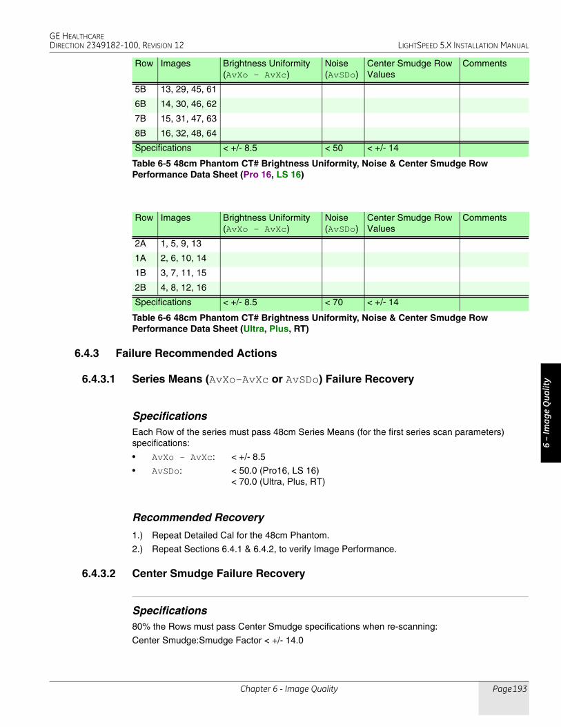
GE HEALTHCAREDIRECTION 2349182-100, REVISION 12 LIGHTSPEED 5.X INSTALLATION MANUAL
Chapter 6 - Image Quality Page 193
6 –
Imag
e Q
ualit
y
6.4.3 Failure Recommended Actions
6.4.3.1 Series Means (AvXo-AvXc or AvSDo) Failure Recovery
SpecificationsEach Row of the series must pass 48cm Series Means (for the first series scan parameters) specifications:
• AvXo - AvXc: < +/- 8.5
• AvSDo: < 50.0 (Pro16, LS 16)< 70.0 (Ultra, Plus, RT)
Recommended Recovery
1.) Repeat Detailed Cal for the 48cm Phantom.
2.) Repeat Sections 6.4.1 & 6.4.2, to verify Image Performance.
6.4.3.2 Center Smudge Failure Recovery
Specifications80% the Rows must pass Center Smudge specifications when re-scanning:
Center Smudge:Smudge Factor < +/- 14.0
5B 13, 29, 45, 61
6B 14, 30, 46, 62
7B 15, 31, 47, 63
8B 16, 32, 48, 64
Row Images Brightness Uniformity(AvXo - AvXc)
Noise(AvSDo)
Center Smudge RowValues
Comments
2A 1, 5, 9, 13
1A 2, 6, 10, 14
1B 3, 7, 11, 15
2B 4, 8, 12, 16
Specifications < +/- 8.5 < 70 < +/- 14
Table 6-6 48cm Phantom CT# Brightness Uniformity, Noise & Center Smudge Row Performance Data Sheet (Ultra, Plus, RT)
Row Images Brightness Uniformity(AvXo - AvXc)
Noise(AvSDo)
Center Smudge RowValues
Comments
Specifications < +/- 8.5 < 50 < +/- 14
Table 6-5 48cm Phantom CT# Brightness Uniformity, Noise & Center Smudge Row Performance Data Sheet (Pro 16, LS 16)

GE HEALTHCAREDIRECTION 2349182-100, REVISION 12 LIGHTSPEED 5.X INSTALLATION MANUAL
Page 194 Section 6.0 - Image Series
Recommended Recovery
1.) If one image of one Row fails (Row fails once):
- Re-scan the 48cm Phantom acquiring two series of 64 images using the same protocol settings as listed in Table 6-3 (on page 190) (Pro 16) or Table6-4 (LS 16, Ultra, Plus, RT).
- Analyze the two 64 re-scanned image series using the Image Analysis IMGSER 48CM -> 16X1.25/120KV/400MA -> AUTO tool.
- Verify that all the 128 re-scanned images do not fail Series Means (AvXo - AvXc and AvSDo) or Center Smudge.
2.) If more than one image of one Row fails (Row fails more than once) or multiple rows are failing:
- Repeat Detailed Cal for the 48cm Phantom.
- Re-scan the 48cm Phantom acquiring three series of 64 images using the same protocol settings as listed in Table 6-3 (on page 190).
- Analyze the three re-scanned image series using the Image Analysis IMGSER 48CM -> 16X1.25/120KV/400MA -> AUTO tool.
- Verify that all the 192 re-scanned images do not fail Series Means (AvXo - AvXc and AvSDo) or Center Smudge.
6.4.3.3 Band or Streak Artifact Failure Recovery
Specifications• Band Artifact: Band Factor< +/- 8.0
• Streak Artifact: Streak Factor< +/- 4.0
Recommended Recovery
1.) Troubleshoot Band or Streak artifact failures, as described in the System Service Manual.
2.) Repeat Detailed Cal for the 48cm Phantom.
3.) Repeat Sections 6.4.1 & 6.4.2, to verify Image Performance.
6.5 20cm QA Phantom Image Series Image Performance Verification
6.5.1 Acquiring the 20cm QA Phantom Image Series
1.) Mount the Phantom Holder on the head-end of the table.
2.) Mount the 20cm QA Phantom on the Phantom Holder.
3.) Align, level, & center the 20cm QA Phantom.
- Align black line on phantom using the internal laser lights.
- Level phantom using bubble level and the Z Axis knob on the Phantom Holder.
- Center phantom using the CENTER PHANTOM procedure in the left head SCANNER UTILITIES selection and the X and Y Axis knobs on the Phantom Holder.
4.) Set up the system to scan three 20cm QA Phantom image series with a Recon of the 1st series.
a.) On the Exam Rx desktop, select NEW PATIENT.
b.) Type the following entries in the listed Patient Information following fields:
* Patient ID:Service
* Name: 20cm QA Phantom Image Series

GE HEALTHCAREDIRECTION 2349182-100, REVISION 12 LIGHTSPEED 5.X INSTALLATION MANUAL
Chapter 6 - Image Quality Page 195
6 –
Imag
e Q
ualit
y
c.) From the Protocol Selection display, click on the Service Tab under Anatomical Selector.
d.) On the Service Protocol Selection window, click on MANUFACTURING.
e.) On the Service Category Protocol List, click on the appropriate Image Series selection as follows:
f.) On the ExamRx protocol parameter display, select the 1st Series.
g.) Set internal Landmark.
5.) Acquire the 1st 20cm QA Phantom image series and one Recon series (MTF and Contrast, Visible Lines).
6.) Acquire the 3rd 20cm QA Phantom image series.
7.) Acquire the last 20cm QA Phantom image series.
6.5.2 20cm QA Phantom Image Series Image Performance Verification
1st QA Phantom Image Series (4 Image MTF Average & Contrast Scale) Image Performance Verification
1.) Launch the Image Analysis Tool.
a.) From the Global Control Palette, click on the Service Desktop.
b.) From the Service Desktop upper navigational bar, click on IMAGE QUALITY TESTS.
c.) In the left navigational area directory, click on IMAGE ANALYSIS.
Note: During the Image Analysis process, you will need to switch between the Service Browser screen (to select the image series to analyze) and the Image Analysis screen (to run a particular Auto 1x analysis test). Use ALT/F1 to bring a window to the front. Use ALT/F3 to send a window to the back.
2.) Using the Auto 1x Tool on the Image Analysis screen, generate a QA#1 MTF and QA#1 Contrast Scale report for the 1st series of the 20cm QA Phantom acquisition.
a.) From the Service Browser window, select the 1st series of the 20cm QA Phantom series acquired in section 6.5.1.
b.) On the Image Analysis Tool window, click on the AUTO 1X diamond shaped button. (See Figure 6-2, on page 189.)
c.) Click on the AUTO 1X rectangular button, select the IMGSER 20CMQA test from the pull-down menu, slide cursor to the right to select QA1 MTF 2X10/120KV/260MA/1S from the test pull-down menu.
d.) Click on the ACCEPT button.
3.) Review the Image Analysis Report data and record the Per Image MTF, 4 Image MTF Average, and Per Image Contrast Scale data for each row in Table 10-7.
a.) Verify the Overall Test Pass/Fail Indicator Window of the Report display indicates PASS. (See Figure 6-3, on page 189.)
b.) Record Per Image MTF and Per Image Contrast Scale data for each image in Table 6-8.
System Protocol - First Protocol - Second
HP60 Image Series QA (none)
HP80 Image Series QA (none)
HP100 Image Series 20cmQA(item # 45.8)
Image Series 20cmQA (item # 45.9)
RT Image Series QA (none)

GE HEALTHCAREDIRECTION 2349182-100, REVISION 12 LIGHTSPEED 5.X INSTALLATION MANUAL
Page 196 Section 6.0 - Image Series
c.) Record the 4 Image MTF Average in Table 6-8.
2nd QA Phantom Image Series (4 Bone Retro Image Visible Lines) Image Perf. Verification
1.) Using the Auto 1x Tool on the Image Analysis screen, generate a Per Image QA#1 Lines report for the 2nd series of the 20cm QA Phantom acquisition.
a.) From the Service Browser window, select the 1st image of the 2nd series of the 20cm QA Phantom series acquired in section 6.5.1 (on page 194).
b.) Click on the AUTO 1X rectangular button, select the IMGSER 20CMQA test from the pull-down menu, and slide cursor to the right to select QA1 LI 2X10/120KV/260MA/1S.
c.) Click on the ACCEPT button. The tool displays a Visible Lines pop-up window.
d.) On the Visible Lines pop-up window, click on the VISIBLE LINE button.
Note: The Image Analysis Tool automatically sets the Window/Level for optimal viewing. If required, adjust Window/Level using the center mouse button.
e.) From the Visible Line pull-down menu, select the letter (A through F) that matches the smallest line pair pattern that you can discern in the Image View Port.
f.) On the Visible Lines pop-up window, click on the OK button.
2.) Review the Image Analysis Report data and record the Per Image QA#1 Visible Lines data for the 1st image in Table 6-8.
a.) Verify the Overall Test Pass/Fail Indicator Window of the Report display indicates PASS. (Refer to Figure 6-3, on page 189.)
b.) Record the Per Image QA#1 Visible Lines data for the 1st image in Table 6-8.
3.) Repeat Steps 1 and 2, for each of the remaining three images in the 2nd 20cm QA Image Series.
Image MTF MTF 4-slice average Contrast Scale Comments
1 N.A.
2 N.A.
3 N.A.
4 N.A.
Specifications N.A. 0.65 to 1.0 110.0 to 130.0 N.A.
Table 6-7 20cm QA#1 Phantom High Contrast Spatial Resolution Image Performance (MTF and Contrast Scale)
Image Line Patterns Visible Comments
1
2
3
4
Specifications B, C, D, E, F N.A.
Table 6-8 20cm QA#1 Phantom High Contrast Spatial Resolution Image Performance(Visible Lines)

GE HEALTHCAREDIRECTION 2349182-100, REVISION 12 LIGHTSPEED 5.X INSTALLATION MANUAL
Chapter 6 - Image Quality Page 197
6 –
Imag
e Q
ualit
y
3rd QA Phantom Image Series (4 Image Visible Holes) Image Performance Verification
1.) Using the Auto 1x Tool on the Image Analysis screen, generate a Per Image QA#2 Holes report for the 3rd series of the 20cm QA Phantom acquisition.
a.) From the Service Browser window, select the 1st image of the 3rd series of the 20cm QA Phantom series acquired in section 6.5.1.
b.) Click on the AUTO 1X rectangular button, select IMGSER 20CMQA from the pull-down menu, and slide cursor to the right to select QA2 HO 2X10/120KV/260MA/1S.
c.) Click on the ACCEPT button. The tool displays a Visible Hole pop-up window.
d.) On the Visible Hole pop-up window, click on the VISIBLE HOLE button.
Note: The Image Analysis Tool automatically sets the Window/Level for optimal viewing. If required, adjust Window/Level using the center mouse button.
e.) From the Visible Hole pull-down menu, select the number (1 through 5) that matches the smallest hole that you can discern in the pattern centered in the image displayed in the Image View Port.
f.) On the Visible Hole pop-up window, click on the OK button.
2.) Review the Image Analysis Report data and record the Per Image QA#2 Visible Holes data for the 1st image in Table 6-9.
a.) Verify the Overall Test Pass/Fail Indicator Window of the Report display indicates PASS. (Refer to Figure 6-3, on page 189.)
b.) Record the Per Image QA#2 Visible Holes data for the 1st image in Table 6-9.
3.) Repeat Steps 1 and 2 for the 3rd, 5th, and 7th images in the 3rd 20cm QA Image Series.
Image Visible HolesViewable atWindow 20
Contrast Factor Comments
1
3
5
7
Specifications See Table 6-9 2.0 to 12.0 N.A.
Table 6-9 20cm QA#2 Phantom Low Contrast Detectability Image Performance(Visible Holes)
Contrast Factor Range(Box 1 Means - Box 2 Means)
Visible Number of Holes Smallest VisibleHole Size
Lower Limit * Upper Limit *
2.00 to 3.99 2 5 7.5 mm
4.00 to 7.99 3 5 5.0 mm
8.00 to 12.00 4 5 3.0 mm
* Required Number of Visible Holes depends on the Contrast Factor
Table 6-10 20cm QA#2 Phantom Visible Hole Specifications

GE HEALTHCAREDIRECTION 2349182-100, REVISION 12 LIGHTSPEED 5.X INSTALLATION MANUAL
Page 198 Section 6.0 - Image Series
Last QA Phantom Image Series (QA#3 Small) Image Performance Verification
1.) Using the Auto 1x Tool on the Image Analysis screen, generate a QA#3 Small report for the last series of the 20cm QA Phantom acquisition.
a.) From the Service Browser window, select the last series of the 20cm QA Phantom series acquired in section 6.5.1 (on page 194).
b.) Click on the AUTO 1X rectangular button, select IMGSER 20CMQA from the pull-down menu, slide cursor to the right to select QA3 SM 2X10/120KV/260MA/1S from the test pull-down menu, and continue to slide cursor to the right to select AUTO. (Refer to Figure 6-3, on page 189.)
c.) Click on the ACCEPT button.
2.) Review the Image Analysis Report data and record the QA3 Small data for the last 20cm QA Image Series in Table 6-11.
a.) Verify the Overall Test Pass/Fail Indicator Window of the Report display indicates PASS. (Refer to Figure 6-3, on page 189.)
b.) Record the QA3 Small data (Row 2A1A and Row 2B1B Series Means AvXc and AvXo - AvXc), QA3 (AvSDc), and the Center Smudge Row data in Table 6-11.
Box Size =196 mm2 to 256 mm215 mm (+/- 1 mm) x 15 mm (+/- 1 mm)31 (+/- 2 pixels) x 31 (+/- 2 pixels)
Box Positions:Box 1= 0 mm x 0 mmBox 2 = 0 mm x -80 mmBox 3 = 80 mm x 0 mmBox 4 = 0 mm x 80 mmBox 5 = -80 mm x 0 mm
3.) Review the last 20cm QA Phantom images acquired in Section 6.5.1 for Rings, Bands, and Streaks using the Image Works Desktop.
a.) From the Global Control Palette, click on the IMAGE WORKS DESKTOP.
b.) From the Image Works Browser window, select the last 20cm QA Phantom series acquired in section 6.5.1.
c.) From the Image Works Browser window, click on the VIEWER button.
d.) While paging through the eight images in the series, analyze images for any Ring, Band, or Streak artifacts. Adjust Window/Level using the center mouse button, as required.
e.) Note any image that appears to have a Ring, Band, or Streak artifact.
4.) Verify any images noted above (step 3e) meet 20cm QA Phantom Ring, Band, or Streak Image Performance requirements.
a.) From the Global Control Palette, click on the Service Desktop.
b.) From the Service Browser window, select an image of the 4th 20cm QA Phantom series acquired in section 6.5.1 that appeared to have a Ring, Band, or Streak while reviewing the series in Image Works.
c.) On the Image Analysis Tool window, click on the AUTO 1X rectangular button, select the IMGSER 20CMQA test from the pull-down menu, slide cursor to the right to select QA3
Row Images AvXc AvXo AvXo - AvXc AvSDo AvSDc Center SmudgeRow Value
Comments
2A1A 1, 3, 5, 7 N.A.
1B2B 2, 4, 6, 8 N.A.
Specifications +3.0 to -3.0 N.A. +3.0 to -3.0 N.A. + 2.9 to +3.5 +2.2 to -2.2
Table 6-11 20cm QA#3 Phantom CT#, Brightness Uniformity, Center Noise & Center Smudge Row Performance Data Sheet

GE HEALTHCAREDIRECTION 2349182-100, REVISION 12 LIGHTSPEED 5.X INSTALLATION MANUAL
Chapter 6 - Image Quality Page 199
6 –
Imag
e Q
ualit
y
SM 2X10/120KV/260MA/1S from the test pull-down menu, and continue to slide cursor to the right to select RING, BAND, or STREAK.
d.) Click on the ACCEPT button.
Note: If required, adjust Window/Level using the center mouse button.
e.) Position and size the Ring, Band, or Streak ROI, using the left cursor button.
Note: To ensure specifications are properly applied, do not adjust the Reference ROIs for the
Ring, Band, and Streak artifact tests. The Reference ROIs are adjustable after the 1st Accept Modification click.
f.) Click on ACCEPT MODIFICATION twice to generate a report.
g.) Verify the Overall Test Pass/Fail Indicator Window of the Report display indicates PASS.
h.) Repeat steps b through g for each image noted in Step 3e.
6.5.3 Failure Recommended Actions
6.5.3.1 1st Image Series (4 Image MTF Average) Failure Recovery
SpecificationsThe 4 Image MTF Average must pass specifications:
4 Image MTF Average:0.65 to 1.00
Recommended Recovery
1.) Repeat Detailed Cal for the 20cm QA Phantom.
2.) Repeat Auto CT# Adjust for the 20cm QA Phantom.
3.) Repeat Sections 6.5.1 & 6.5.2, to verify Image Performance.
6.5.3.2 2nd Image Series (Visible Lines) Failure Recovery
SpecificationsThe Largest 5 line pair patterns (coded F, E, D, C, and B) must be visible for each of the four images in this series.
Recommended RecoveryNote: The most common failure for this test is that the phantom has air bubbles that are obscuring the line
pair patterns.
1.) Carefully inspect the 20cm QA Phantom for air bubbles. If required, refill the phantom with water, to eliminate all air bubbles.
2.) Repeat Sections 6.5.1 & 6.5.2, to verify Image Performance.

GE HEALTHCAREDIRECTION 2349182-100, REVISION 12 LIGHTSPEED 5.X INSTALLATION MANUAL
Page 200 Section 6.0 - Image Series
6.5.3.3 3rd Image Series (Visible Holes) Failure Recovery
SpecificationsThe number of visible holes in this image series must pass specifications as follows:
• Contrast Factor = 2.0 to 3.99:Minimum of 2 holes must be visible (10mm & 7.5mm)
• Contrast Factor = 4.0 to 7.99:Minimum of 3 holes must be visible (10mm, 7.5mm & 5mm)
• Contrast Factor = 8.0 to 12.0:Minimum of 4 holes must be visible (10mm, 7.5mm, 5mm, & 3mm)
Recommended Recovery
1.) Repeat Detailed Cal for the 20cm QA Phantom.
2.) Repeat Auto CT# Adjust for the 20cm QA Phantom.
3.) Repeat Sections 6.5.1 & 6.5.2, to verify Image Performance.
6.5.3.4 4th Image Series Failure Recovery
Series Means
SPECIFICATIONSBoth Rows (2A1A, 1B2B) of the series must pass QA#3 Series Means specifications:
• AvXc: < +/- 3.0
• AvXo - AvXc: < +/- 3.0
RECOMMENDED RECOVERY
1.) Repeat Detailed Cal for the 20cm QA Phantom.
2.) Repeat Auto CT# Adjust for the 20cm QA Phantom.
3.) Repeat Sections 6.5.1 & 6.5.2, to verify Image Performance.
QA#3 (AvSDc)
SPECIFICATIONSBoth Rows (2A1A, 1B2B) of the series must pass QA#3 AvSDc specifications:
• AvSDc (< 5K Scans):2.90 to 3.50
• AvSDc (> 5K Scans):2.80 to 3.60
RECOMMENDED RECOVERY
1.) Repeat Detailed Cal for the 20cm QA Phantom.
2.) Repeat Auto CT# Adjust for the 20cm QA Phantom.
3.) Repeat Sections 6.5.1 & 6.5.2, to verify Image Performance.

GE HEALTHCAREDIRECTION 2349182-100, REVISION 12 LIGHTSPEED 5.X INSTALLATION MANUAL
Chapter 6 - Image Quality Page 201
6 –
Imag
e Q
ualit
y
Center Artifact or Center Smudge
SPECIFICATIONSAll eight images of the series must pass 20cm QA#3 Center Artifact and Center Smudge specifications:
• Center Artifact Factor:+/- 3.5
• Center Smudge Factor:+/- 2.2
RECOMMENDED RECOVERY
1.) Repeat Detailed Cal for the 20cm QA Phantom.
2.) Repeat Auto CT# Adjust for the 20cm QA Phantom.
3.) Repeat Sections 6.5.1 & 6.5.2, to verify Image Performance.
Ring, Band, or Streak Artifact Failure Recovery
SPECIFICATIONS• Ring Artifact: Ring Factor < +/- 4.8
• Band Artifact: Band Factor+/- 2.8 from 0cm to 8.5cm< +/- 2.8 > 8.5cm
• Streak Artifact: Streak Factor< +/- 4.0
RECOMMENDED RECOVERY
1.) Troubleshoot Ring, Band or Streak artifact failures as described in the Service Manual.
2.) Repeat Detailed Cal for the 20cm QA Phantom.
3.) Repeat Sections 6.5.1 & 6.5.2, to verify Image Performance.

GE HEALTHCAREDIRECTION 2349182-100, REVISION 12 LIGHTSPEED 5.X INSTALLATION MANUAL
Page 202 Section 7.0 - System Functional Test
Section 7.0System Functional Test
Use the system tests in the following sections to exercise all aspects of the system and to ensure system integrity before releasing to the customer. Although the means, standard deviation, and resolution specifications do not apply during system functional tests, treat any artifact or image anomaly as a failure.
If you encounter a failure during the system tests:
• Record any evidence of artifacts, such as rings, streaks, shading, cupping, noise, or center artifacts.
• Correct artifacts, system test, or image series failures when they occur. Any delay in repairs could increase the number of retests.
1.) Place the QA phantom on the cradle.
- Drive the table to an elevation of 100.
- Align the line on the phantom with the internal laser lights.
Never scan above 50mA without first placing a phantom in the field of view. Levels in excess of 50mA can cause temporary radiation damage to the detector that lasts several hours. If you acquire image series cals with a radiation damaged detector, the cals may cause artifacts in subsequent image series scans.
2.) Select the service protocol, SYSTEM SCAN/CUST QUAL RELI.
3.) Run each series.
Note: Stop the service protocol after the second helical series. It is not necessary to proceed past that point in the protocol.
4.) Using Diagnostic Data Analysis, review the MSD Plots for each AIR scan.
5.) Complete the scans.
Section 8.0Save System State
Use the following commands to create the System State DVD.
1.) Load a DVD into the mod drive on the front of the console.
2.) If you are not on the Service Desktop, click on the SERVICE DESKTOP icon.
3.) Click on the PM icon.
4.) Select SYSTEM STATE to open the System State Save/Restore menu.
5.) Select ALL
6.) Select SAVE
7.) When the save operation completes, select FILE and QUIT from the pull down menu.
8.) Remove the MOD from the drive

GE HEALTHCAREDIRECTION 2349182-100, REVISION 12 LIGHTSPEED 5.X INSTALLATION MANUAL
Chapter 7 - Customer Options Installation & Verification Page 203
7 –
Cust
omer
Opt
ions
Chapter 7Customer Options Installation & Verification
Note: Only use the Installation manual that arrives with your system for installation. Any other revisions of this manual may not exactly match your system.
Section 1.0CT Options
Injector functional tests completed.
AWW functional tests completed.
Filming/Camera/DASM functional tests completed.
UPS functional tests completed.
Network items installed and functional tests completed.
Verify that all customer software options are installed and functional.
* Direct 3D
* SmartScore Pro
* CT Perfusion
Teleradiology Connections (Refer to Section 10.0 on page 230)
Auxiliary Monitor
* Flat Panel
* CRT
Section 2.0Install Options
Refer to:
• GE Prints and schematics for mechanical (physical) location of option
• FDO shipment for identification of items
• Installation Specialist for installation instructions if they differ from print
2.1 Camera (Filming Device)
Refer to documentation shipped with camera
• Chapter 3 of this manual
• DICOM 2210573 GE Document
• DICOM Print 2152913

GE HEALTHCAREDIRECTION 2349182-100, REVISION 12 LIGHTSPEED 5.X INSTALLATION MANUAL
Page 204 Section 2.0 - Install Options
2.2 Injector
Refer to documentation shipped with the injector.
Complete a Functional test of the injector.
The position of the ceiling mount assembly must allow the ceiling stand movement and gantry to tilt, typically 20 degrees, without interference.
2.3 Advantage Workstation (AW)
Refer to the directions provided:
• Pre-install 2111833
• Service 2111831
2.4 Other Options
Refer to CT-2211224-100 Lightspeed Options for all other options.
Figure 7-1 Ceiling Mount Position

GE HEALTHCAREDIRECTION 2349182-100, REVISION 12 LIGHTSPEED 5.X INSTALLATION MANUAL
Chapter 7 - Customer Options Installation & Verification Page 205
7 –
Cust
omer
Opt
ions
Section 3.0DICOM Network Introduction
LightSpeed systems support two basic Networking Protocols:
• Advantage NET (IC, Signa 4.X, CT-HLA, CT/I …)
• DICOM (CT/I, CT Synergy, Advantage Workstations, …)
DICOM NETWORK INTRODUCTIONDICOM networks basically operate on the tasks or services that various devices on the network use or provide. These services are labeled as Application Entity Titles (AE Titles). The CT scanner system is a user of six DICOM Network Services and is a provider of two DICOM Services:
AS A DICOM SERVICE USER:• Send or Push images to another network device.
• Send or Push images to a DICOM Printer.
• Review image database on another device and retrieve or Pull selected images from that device (Query/Retrieve User).
• Send or Push images to a an image storage device and obtain confirmation that the images have been archived (Storage Commitment).
• Obtain Patient Worklist Information from the Hospital HIS/RIS System.
• Store images on MOD media.
AS A DICOM SERVICE PROVIDER:• Receive Pushed images from another network device
• Allow another network device to review the image database and to retrieve or Pull selected images (Query/Retrieve Provider)
For each DICOM Service that the CT system will be a User (except for storing images on MOD media), you must declare this device on the CT system using three menu selections. For some devices, you must declare not only the device, but each service (AE Title) that the device provides. For example, you may be required to declare a PACS System twice on the CT system: once as a destination to push images and, second, as destination that provides storage commitment capability after images have been pushed.
For each DICOM Service that the CT system will be a Provider, you must declare the CT system on the network device that will be using these services.
Information required to complete configuring a hospital DICOM network is provided by the hospital network administrator (hostnames, IP Addresses) and the DICOM Conformance Statement document (AE Titles, Port Numbers) provided with each DICOM compatible network device on the network.

GE HEALTHCAREDIRECTION 2349182-100, REVISION 12 LIGHTSPEED 5.X INSTALLATION MANUAL
Page 206 Section 4.0 - Before You Start
Section 4.0Before You Start
4.1 Network Physical Requirements
Before setting up the CT scanner system on the hospital network, verify the following physical items are complete:
• Scanner console, monitor, keyboard, and mouse are installed and connected.
• CT system power is ON
• Hospital Ethernet network RJ45 Class IV twisted pair cable is connected to the scanner console network receptacle.
• Hospital network connection is operational and is running 10baseT or 100baseT.
4.2 Network Identity Information
To declare the CT system on the network, ensure the following network identity information is available from the Hospital Network Administrator:
• Hostname (No more than 16 Characters)
• Internet Protocol (IP) Address
• Subnet Net Mask IP Address (if applicable)
• Broadcast Address (if applicable)
4.3 Scanner to DICOM Remote Hosts Network Information
To declare DICOM remote hosts (PACS systems, archival devices, review workstations) on the CT system, ensure the following information is available for each remote host:
From the Hospital Network Administrator:
• Hostname
• Internet Protocol (IP) Address
• Network Protocol (DICOM for CT Systems)
From the Remote Host Device DICOM Conformance Statement Document:
• DICOM Application Entity Title or AE Title (DICOM service that remote host provides or uses)
• DICOM Listening Port Number
4.4 Scanner to DICOM HIS/RIS Interface Network Information
To declare DICOM Hospital HIS/RIS Interface devices (Mitra and others) on the CT System, ensure the following information is available:
From the Hospital Network Administrator: Internet Protocol (IP) Address
From the HIS/RIS Interface Device DICOM Conformance Statement Document:
• DICOM Application Entity Title or AE Title (DICOM Service that the HIS/RIS interface provides)
• DICOM Listening Port Number

GE HEALTHCAREDIRECTION 2349182-100, REVISION 12 LIGHTSPEED 5.X INSTALLATION MANUAL
Chapter 7 - Customer Options Installation & Verification Page 207
7 –
Cust
omer
Opt
ions
4.5 Scanner to DICOM Printers Network Information
To declare DICOM on the CT System, ensure the following information is available for each printer:
From the Hospital Network Administrator:
• Hostname
• Internet Protocol (IP) Address
From the Printer DICOM Conformance Statement Document:
• DICOM Application Entity Title or AE Title (DICOM service that remote host provides or uses)
• DICOM Listening Port Number

GE HEALTHCAREDIRECTION 2349182-100, REVISION 12 LIGHTSPEED 5.X INSTALLATION MANUAL
Page 208 Section 5.0 - Declaring the System on the Hospital Network
Section 5.0Declaring the System on the Hospital Network
5.1 Enter Configuration Routine
1.) On the OC, open a Unix shell window.
2.) Enter root as a superuser:
Type: su - ENTER at the prompt.
Type: #bigguy ENTER at the password prompt.
3.) Change directory to scripts:
Type: cd /user/g/scripts ENTER at the root prompt.
4.) Launch the Install Utility:
Type: reconfig ENTER at the prompt.
The OC displays the Install Utility Window as shown in Figure 7-2.
Figure 7-2 Install Utility Window
5.) Enter the Configuration Routine:
Using the mouse, click on the CONFIG button.
The OC displays the System Configuration - System Settings screen.

GE HEALTHCAREDIRECTION 2349182-100, REVISION 12 LIGHTSPEED 5.X INSTALLATION MANUAL
Chapter 7 - Customer Options Installation & Verification Page 209
7 –
Cust
omer
Opt
ions
5.2 Configure Network Settings
This screen provides the ability to declare the CT system on a hospital network. Key information such as Host Name, IP Address, Net Mask (for CT systems on a subnet) must be obtained from the hospital network administrator.
1.) Select the NETWORK button to display the Network Settings screen as shown in Figure 7-3.
2.) Enter the Suite Name.
The Suite Name is a means of identifying this particular CT system as a part of a group of CT Systems in a suite configuration. This Suite Name will appear on all image headers.
The Suite Name must start with a letter, followed by three alphanumeric characters (total MUST be four characters long). The name of the OC interface will be <Suite Name>_oc and the SBC interface will be <Suite Name>_sbc.
Figure 7-3 Network Settings Screen
3.) Enter the hospital provided Host Name.
The Host Name identifies the network hostname and AE Title of the CT system.
The Host Name:
- MUST NOT be <Suite Name>_oc or <SUITE NAME>_OC.
- MUST NOT exceed 16 Characters.
- MUST only contain the following characters: A through Z, a through z, 0 through 9, - and _
4.) Enter the hospital provided IP Address.
5.) Enter the hospital provided Net Mask (if the CT system is on a subnet).
6.) Enter the Broadcast Address:
The Broadcast Address should be the same as the IP Address except for the bits of the host id portion (last digit group) set to 1s or 0s depending on the configuration of the network. The standard default is 1s but older SunOS machines used 0s.

GE HEALTHCAREDIRECTION 2349182-100, REVISION 12 LIGHTSPEED 5.X INSTALLATION MANUAL
Page 210 Section 5.0 - Declaring the System on the Hospital Network
Example: If the IP Address is 192.100.9.17, the Broadcast Address should be 192.100.9.255 if the network is configured to use 1's to specify the broadcast address.
If the network contains genesis based scanners or other SunOS 3.5 or 4.1 computers, the Broadcast Address should be 192.100.9.0.
7.) Enter the hospital provided Default Gateway IP Address in the Default Gateway field (if applicable). If the site network does not use a default gateway, leave the field blank.
8.) Select NIS (Yellow Pages database) Advanced Option only if requested by the hospital network administrator as follows:
a.) Select ADVANCED OPTIONS button on the Network Settings screen.
b.) Select Use NIS? button.
c.) Enter the hospital provided Domain Name.
9.) Record all the Network parameters in the Software Installation Procedures Document, or on the worksheet in 2.2 on page 152.
5.3 Initiate System Reconfiguration
1.) Select ACCEPT on the System Configuration Screen.
The system loads the application software, OS patches, and kernal changes, and configures the system on both the OC and the SBC.
This loading process takes approximately 15 minutes. While the load is going on, the results are displayed in a shell window, which closes when the loading process is complete. All the window output is logged to a file named:
/var/adm/install.log.YYYYMMDDWWWHHMMSS.
(Where YYYYMMDDWWWHHMMSS is the Date/Time that the loading process was started.)
2.) When the loading process and configuration changes are complete, the system displays a prompt to reboot. Click on YES.
3.) The system will automatically login as ctuser after the reboot. Select OK on the Autostart Disabled popup message.
4.) To startup Applications, in the console shell window, type startup ENTER.

GE HEALTHCAREDIRECTION 2349182-100, REVISION 12 LIGHTSPEED 5.X INSTALLATION MANUAL
Chapter 7 - Customer Options Installation & Verification Page 211
7 –
Cust
omer
Opt
ions
Section 6.0Declaring Remote Hosts on the CT System
6.1 Enter Remote Host Configuration Screen
1.) On the OC, select the IMAGE WORKS icon.
2.) Select NETWORK.
6.2 Declaring Advantage NET Remote Hosts on the Scanner
Use Advantage NET Protocol networks to communicate with older CT or MR Systems (MR Signa 4.x, CT-HLA, CT/I Systems, and Workstations that support the Advantage NET protocol). Advantage NET Protocol does not offer full compatibility with LightSpeed DICOM formats.
Repeat the following procedure for each Advantage NET Remote Host device that the customer expects to have this CT system communicating with.
1.) Select REMOTE HOSTS from the pull down menu. The system displays the Remote Host Parameter Screen as shown in Figure 7-4.
Figure 7-4 Advantage Net Network Protocol Parameter Settings
2.) Enter the hospital provided Host name.
3.) Enter the hospital provided Network Address (IP Address).

GE HEALTHCAREDIRECTION 2349182-100, REVISION 12 LIGHTSPEED 5.X INSTALLATION MANUAL
Page 212 Section 6.0 - Declaring Remote Hosts on the CT System
4.) Select ADVANTAGE NET as the Network Protocol.
The systems automatically de-highlights the remaining parameter fields on the Remote Host parameter selection screen. These are dedicated DICOM protocol parameters and do not apply to Advantage NET type devices.
5.) Select SAVE to store the parameter settings of the remote host.
6.3 Declaring DICOM Remote Hosts on the CT Scanner
Use DICOM protocol networks to communicate to DICOM devices such as CT/i, CT Synergy, DLX, MR Lx, and third party hosts.
Repeat the following procedure for each DICOM remote host device that the customer expects to have this CT system communicating with.
1.) Select REMOTE HOSTS from the pull down menu. The system displays the Remote Host Parameter screen as shown in Figure 7-5.
Figure 7-5 DICOM Network Setting Protocol Parameter Settings
2.) Enter the hospital provided Host name.
3.) Enter the hospital provided Network Address (IP Address).
4.) Select DICOM as the Network Protocol.
The system automatically highlights the remaining parameter fields on the Remote Host parameter selection screen. These are dedicated DICOM Protocol parameters.
5.) Enter the TCP/IP Listening Port Number from the DICOM Conformance Statement provided with the device.

GE HEALTHCAREDIRECTION 2349182-100, REVISION 12 LIGHTSPEED 5.X INSTALLATION MANUAL
Chapter 7 - Customer Options Installation & Verification Page 213
7 –
Cust
omer
Opt
ions
6.) Enter the AE Title from the DICOM Conformance Statement provided with the device.
Application Entity Titles (also known as ACR-Nema or Dicom Name) refer to the DICOM Network Services that a device provides to the CT System. For most devices, the AE Title is the same as the hostname (CT systems are equipped with this feature).
However, some devices such as PACS systems may have separate AE Titles and port numbers for each of the services that the PACS system provides. In these cases, you must enter a separate remote host (same hostname and IP Address) for each of the independent AE Title Services that the host provides (one host as an image push-to destination, another host as a query/retrieve provider, and another host as a storage/commitment provider).
Be sure to review the DICOM Conformance Statement for each device that will provide a remote host network service for the CT system (image push-to or store destination, Query/Retrieve, and Storage Commitment) to ensure that each service is correctly configured.
7.) Select the correct Archive Node choice for the device. The Archive Node selection field defines the ability of the remote host to act as a DICOM Storage/Commitment provider and indicate to the operator that a study/series/image was archived. Select:
- AUTO to have the CT system automatically check to see if the designated remote host is a DICOM Storage/Commitment Provider.
- YES if the device is the hospital designated DICOM Storage/Commitment Provider. During an Application Study Archive process, the local browser screen will indicate Archive Status = Y to the operator.
- NO if the device is not a DICOM Storage/Commitment Provider.
8.) Select the correct Access to local host: settings. These two selections allow you to selectively block the remote host from using the LightSpeed DICOM services as a provider (image push-to destination, and a Query/Retrieve provider).
- Send Images? Set to YES if the customer wants the CT system to be able to have images pushed to the system from the applicable remote host. Set to NO if the customer wants to block an image push from the applicable remote host.
- Query/retrieve images? Set to YES if the customer wants the remote host to be able to review the image database (query) and pull selected images from the database. Set to NO if the customer does not want the remote host to have this ability.
9.) Select the correct Custom search? setting. This selection allows the CT scanner to selectively search through the remote host's image database when the operator is using remote browser screen to query the remote host. The search parameters that the CT system allows the customer to use are: last name contains, patient ID, exam number, accession number, and exam date.
- Select ON if the device supports custom searches as part of the devices Query/Retrieve DICOM Provider service.
- Select OFF if the device does not support custom searches.
10.) Record all the remote host network parameters for each remote host in the Software Installation Procedures Document.
11.) Select SAVE to store the parameter settings of the remote host.

GE HEALTHCAREDIRECTION 2349182-100, REVISION 12 LIGHTSPEED 5.X INSTALLATION MANUAL
Page 214 Section 7.0 - Declaring the CT System on Remote Hosts
Section 7.0Declaring the CT System on Remote Hosts
7.1 Declaring the Scanner on Advantage NET Protocol Devices/Systems
Refer to the appropriate service manual provided with the Advantage NET Protocol device or system to find instructions how to declare the CT System as an Advantage NET remote host.
7.2 Declaring the Scanner on DICOM Protocol Devices/Systems
Refer to the appropriate Service Manual provided with the DICOM protocol device or system to find instructions how to declare the CT System as a DICOM remote host.
The CT System provides two DICOM Services as a provider to remote hosts:
• A remote host can push images to the CT image database.
• A remote host can review the CT image database (query) and pull selected images (retrieve).
Use the following parameter information to configure the DICOM device/system to either push images to the CT scanner and/or perform a Query/Retrieve operation:
• Hostname: Provided by the Hospital Network Administrator. Exactly the same scanner assigned hostname entered in Network Configuration Screen.
• Application Entity Title: Exactly the same entry as the Hostname.
• Network Address: Provided by the Hospital Network Administrator. Exactly the same scanner assigned IP Address entered in Network Configuration Screen.
• Network Protocol: DICOM 3.0.
• Port Number: For all DICOM service that the CT System provides, use 4006.
• Provider Type: This field concerns the LightSpeed DICOM Query/Retrieve provider capability. All CT systems are wtudy root systems, which allow queries at the exam, series, and image level.
• Support Worklist: This field concerns whether a DICOM Query/Retrieve provider capable device or system supports a filter search of the image database. All CT systems support a filtered search of the image database as part of the LightSpeed DICOM Query/Retrieve provider capability.

GE HEALTHCAREDIRECTION 2349182-100, REVISION 12 LIGHTSPEED 5.X INSTALLATION MANUAL
Chapter 7 - Customer Options Installation & Verification Page 215
7 –
Cust
omer
Opt
ions
Section 8.0DICOM HIS/RIS Setup
8.1 Prerequisites
Most hospital HIS/RIS systems are not DICOM compatible and require a DICOM HIS/RIS Worklist Interface to provide patient scheduling information to the CT system. Contact your local HNS support engineer to determine exactly what DICOM HIS/RIS Interface is appropriate for the customer.
In addition, the CT system must have the ConnectPRO software option installed to utilize the DICOM Protocol Worklist capability.
8.2 Loading ConnectPRO Software Option on the CT System
1.) If you are not on the Service Desktop, click on the SERVICE DESKTOP icon.
2.) Click on the UTILITIES icon.
3.) Click on INSTALL.
4.) Select INSTALL OPTIONS and click START. The console displays the Software Options window as shown in Figure 7-6.
Figure 7-6 Options Window when First Selected
5.) Insert the ConnectPRO Options MOD into the MOD drive.
6.) Click on OK to continue.

GE HEALTHCAREDIRECTION 2349182-100, REVISION 12 LIGHTSPEED 5.X INSTALLATION MANUAL
Page 216 Section 8.0 - DICOM HIS/RIS Setup
7.) On the Software Option window, select the CONNECTPRO option in the Available Options window.
8.) Click on the INSTALL button.
The console may display a message box during the software loading operation. When the system has completed loading the software:
- the Installed Options window displays the ConnectPRO option, and
- the console displays the ConnectPro Setup window as shown in Figure 7-7.
Figure 7-7 ConnectPro Setup Screen
9.) Enter the hospital provided HIS Server IP Address.
10.) Enter the HIS Server AE Title from the DICOM HIS/RIS Interface device DICOM Conformance Statement document.
11.) Enter the HIS Server AE Port # from the DICOM HIS/RIS Interface device DICOM Conformance Statement document.
12.) Record all the ConnectPRO HIS/RIS Network parameters in the Software Installation Procedures document.
The system will automatically load the LightSpeed CT Server AE Title (Hostname of the system).
13.) Click on the ACCEPT button. The system will check valid setup entries, execute a perl script that makes changes to the configuration files for HIS/RIS, and return to the Software Option window shown in Figure 7-6.
14.) Click on the QUIT button and the subsequent OK button in the message window.
15.) Remove the MOD from the MOD drive, and write protect the side containing the ConnectPRO option.

GE HEALTHCAREDIRECTION 2349182-100, REVISION 12 LIGHTSPEED 5.X INSTALLATION MANUAL
Chapter 7 - Customer Options Installation & Verification Page 217
7 –
Cust
omer
Opt
ions
Section 9.0DICOM Filming Devices Setup
9.1 Prerequisites
Before configuring DICOM filming devices (cameras, printers) on the CT System, ensure the following are complete:
• Filming Device Service Representative to assist in camera/printer setup for best image quality film presentation.
• Hospital DICOM network is operational.
• Filming device is connected to the DICOM network with the correct filmer DICOM interface.
• Filming device is DICOM protocol compatible.
• Filming device DICOM Conformance Statement document is available.
Note: Filmer DICOM Application Entity Titles may be site specific. Make sure that you check with the Filming Device Service Representative and the hospital network administrator to ensure you are using the correct AE Title for the destination filming device.
9.2 Declaring DICOM Filming Devices on the CT System
NOTICEPotential For
Data Loss
Empty all filming queues before modifying camera parameters.
This section contains procedures for recording important Camera setup information. Use the table(s) at the end of this section to record information from the setup screens.
1.) Click on the SERVICE DESKTOP button.
2.) On the Desktop Toolbar select UTILITIES -> INSTALL -> INSTALL CAMERA. The Install Camera window appears, along with a warning message pop-up box, to remind you that all filming queues must be empty before you begin to update or delete a camera.
3.) The Graphical User Interface displayed shows a list of cameras installed (See Figure 7-9). First, you must click OK in the warning message box. See Figure 7-8.
Figure 7-8 Warning Screen

GE HEALTHCAREDIRECTION 2349182-100, REVISION 12 LIGHTSPEED 5.X INSTALLATION MANUAL
Page 218 Section 9.0 - DICOM Filming Devices Setup
4.) Now you are asked a series of questions.
a.) To add a new camera, click the ADD button (See Figure 7-9).
Figure 7-9 Printer Configuration GUI
b.) A dialog window for the camera type (DASM/DICOM) appears. If no DASM is detected during the OC boot, the DASM button will be disabled (Figure 7-10). If a DASM is present and has not been detected, reboot the OC and run the camera configuration tool again.
Figure 7-10 Dialog Box for camera Type (with and without DASM)

GE HEALTHCAREDIRECTION 2349182-100, REVISION 12 LIGHTSPEED 5.X INSTALLATION MANUAL
Chapter 7 - Customer Options Installation & Verification Page 219
7 –
Cust
omer
Opt
ions
5.) To add a new laser camera, click DASM in the camera type dialog box. This brings up a list of available camera models. Select the appropriate model form the list and click SELECT (See Figure 7-11). Now you must configure it.
Figure 7-11 Camera Model Dialog (with DASM)
a.) DASM Interface is automatically detected as either Analogue or Digital
b.) Two Laser Options are available for laser cameras: SLIDES and ZOOM. Set this option only if the camera being installed supports slides and zoom. Setting the option allows it to be enabled or disabled at the application level.
c.) Camera manufactures provide two (2) Magnification Type options for cameras. The SMOOTH resolution blurs the image, while the SHARP resolution makes the image pixels more pronounced. The default is smooth.
Note: To film good images, and have them look like images filmed by other GE CT products, the following camera settings are suggested:
Kodak:SMOOTHDupont/Sterling:SMOOTH3M/Imation (Laser Camera):SHARP3M/Imation (Dry View):SMOOTHAgfa: SMOOTH
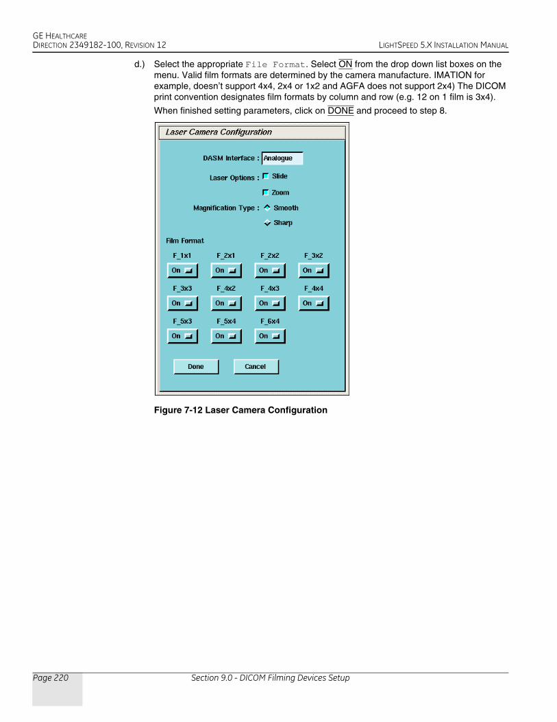
GE HEALTHCAREDIRECTION 2349182-100, REVISION 12 LIGHTSPEED 5.X INSTALLATION MANUAL
Page 220 Section 9.0 - DICOM Filming Devices Setup
d.) Select the appropriate File Format. Select ON from the drop down list boxes on the menu. Valid film formats are determined by the camera manufacture. IMATION for example, doesn’t support 4x4, 2x4 or 1x2 and AGFA does not support 2x4) The DICOM print convention designates film formats by column and row (e.g. 12 on 1 film is 3x4).
When finished setting parameters, click on DONE and proceed to step 8.
Figure 7-12 Laser Camera Configuration

GE HEALTHCAREDIRECTION 2349182-100, REVISION 12 LIGHTSPEED 5.X INSTALLATION MANUAL
Chapter 7 - Customer Options Installation & Verification Page 221
7 –
Cust
omer
Opt
ions
6.) To add a new DICOM camera, click on ADD and then DICOM in the dialog box that appears.
a.) A list of camera models appears (See Figure 7-13). Select the appropriate model from the list and click SELECT. Clicking SELECT presets all the parameters to that models except the Network parameters.
Figure 7-13 Camera Model Dialog (DICOM)
Note: It is advised to recheck the preset information with the camera manufacturer’s representative. Selection of a different camera model clears the Image Quality parameters, because these are camera manufacturer dependent.
b.) Enter the Network Parameters (See Figure 7-14):
Device Name - A unique name used to identify the camera.
Host Name - DICOM print server host name, as defined by the hospital.
IP Address - DICOM print server IP address, as defined by the hospital.
AE Title - DICOM print server application entity title, as defined by the print server. You should consult the manufacturers DICOM Conformance Statement.
TCP/IP Listen Port - DICOM print server TCP/IP listen port, as defined by the server. You should consult the manufacturers DICOM Conformance Statement.
Comments - Optional comments used by the DICOM print server.
Note: The Application Entity Title for the Camera may be site specific. Make sure that you check with the Camera Manufacturer’s Representative and the hospital network administrator to ensure you are using the correct AE Title for the destination DICOM Print Camera.

GE HEALTHCAREDIRECTION 2349182-100, REVISION 12 LIGHTSPEED 5.X INSTALLATION MANUAL
Page 222 Section 9.0 - DICOM Filming Devices Setup
Figure 7-14 DICOM Camera Configuration
c.) Medium Type specifies the type of film being used. Currently, only BLUE FILM and CLEAR FILM are suported.
d.) Set Destination to the final location for film output: either MAGAZINE or PROCESSOR.
e.) Orientation selects film orientation. Ony PORTRAIT is currently supported.
f.) Set the Magnification Type. This parameter selects the algorithm used to interpolate pixels for proper film resolution. Set this parameter after consulting the camera manufacture to ensure optimal image quality. Choices are describe below:
> None No interpolation. This option is not suported by all cameras.
> Replicate Adjacent pixels are interpolated. This can result in "pixelized" images. This algorithm is not normal prefrerred.
> Bilinear A 1st order interpolation of pixels. Results in images usaually described as blurred. This algorithm is not normal prefrerred.
Comment: Formost Camera
Manufacturers,the preferred
selection isCUBIC.
> Cubic A 3rd order interpolation. Used with a large number of possible formulations. Camera manufactures define parameters called "smoothing type" to set coefficients used in this algorithm. The implementation of these "smoothing soefficients" is camera dependent.
g.) Select the Standard Film Formats. Select the film format by choosing ON in the pull-down menu box located below each selection. See Figure 7-14. Valid film formats are set by the camera manufacture. IMATION for example, doesn’t support 4x4, 2x4 or 1x2 and

GE HEALTHCAREDIRECTION 2349182-100, REVISION 12 LIGHTSPEED 5.X INSTALLATION MANUAL
Chapter 7 - Customer Options Installation & Verification Page 223
7 –
Cust
omer
Opt
ions
AGFA does not support 2x4) The DICOM print convention designates film formats by column and row (e.g. 12 on 1 film is 3x4).
h.) After the camera has been configured, click the ADVANCED button. This creates the camera device file for you automatically and pops up the Advanced Parameters screen. See Figure 7-15.
Figure 7-15 Advanced Parameters (Camera Attribute Dialog)
7.) Advanced camera parameters control the image quality of films.
Note: For more information on the proper settings for these parameters, please see the Camera’s DICOM Print Device Conformance Statement or the Camera Manufacturer Representative.
You may need to refer to a copy of the Conformance Statement as you are working with the Camera Manufacturer’s Representative, to correctly set up the DICOM Print Camera I/Q and Time-out Settings.
a.) Configuration - This parameter is camera manufacturer dependent as is typically used to specify the image contrast. The Configuration field may be up to 1024 characters long. The field will scroll automatically as text is entered. To review your entry, simply click and hold the middle mouse button, while the cursor is in the field, and drag the mouse towards the right (or left) as needed.
Note: Recommended Configuration Setting Values:
Agfa Drystar (MG3000) PERCEPTION_LUT=KANAMORI (100)Imation Dryview (8700) LUT=0,7Kodak Laser Printer 190 CS434\CN0\PD1.20
b.) Smoothing Type - Set Smoothing Type to ON, and input the selected value. This parameter is used when the magnification type is CUBIC. It represents the coefficient for the image resolution alogrithm.This parameter is camera manufacturer dependent, and should be re-verified with your radiology department.

GE HEALTHCAREDIRECTION 2349182-100, REVISION 12 LIGHTSPEED 5.X INSTALLATION MANUAL
Page 224 Section 9.0 - DICOM Filming Devices Setup
Note: Recommended Smoothing Type Starting Values and Ranges:
Agfa DryStar (MG3000) Start Value: 140 Range: 137-150Imation Dryview (8700) Start Value: 3 Range: 3-13Kodak Laser Printer 190 Start Value: Enhanced Range: Normal
c.) Minimum and Maximum Density - Used to set brightness of the images on film. The range of values is 0-4095, although the valid range for a specific camera is manufacture dependent. For Maximum Density, input the correct value into the text box. For Minimum Density, set it to ON and input the correct value in the text box.
Note: Recommended Minimum and Maximum Density Starting Values:
Agfa Drystar (MG3000) Min.: 20 or 23 Max: 300Imation Dryview (8700) Min.: (Blank) Max: 300Kodak Laser Printer 190 Min.: 20 Max: 300
d.) Empty Image Density - This parameter sets the density for empty film viewports. Typically, BLACK is used but WHITE is an avialble option. The minimum and maximum density values are used as the representation.
e.) Border Density - This sets the density for the border used around the film viewports. Typically, BLACK is used but WHITE is an available option. The minimum and maximum density values are used as the representation.
f.) Film Size - Allows the system to specify a particular film size, if selected.
g.) Trim - YES produces a white (clear) box surrounding each image.
h.) Priority - This sets the print priority.
i.) If you have completed entry of advanced parameters, click DONE.
CAMERA DATA TABLES: TO LOCATE INSTALL CAMERA INFORMATION: CLICK ON THE SERVICE DESKTOP BUTTON. ON THE DESKTOP TOOLBAR SELECT UTILITIES -> INSTALL -> INSTALL CAMERA. THE INSTALL CAMERA WINDOW APPEARS. SELECT EACH OF THE CAMERAS THAT ARE INSTALLED FROM THE LIST OF INSTALLED CAMERAS, AND CLICK ON UPDATE TO VIEW THE CAMERA’S SETTINGS. RECORD THE VALUES USED TO SET UP EACH CAMERA IN THE TABLES THAT FOLLOW. EXTRA TABLES ARE PROVIDED FOR MULTIPLE CAMERAS
DASM CAMERA #1 SETUP
Note: You can determine this information by looking at the contents of the following files:
• For a DASM Camera: /usr/g/ctuser/app-defaults/devices/camera.dev
• For a DICOM Print Camera: /usr/g/ctuser/app-defaults/devices/name.cfgwhere, name.cfg is the camera device name from the printer configuration GUI.
Example: more <filename from above> ENTER
GUI SETTING SELECTIONS VALUECamera Type Model Type of Camera
DASM Type Digital or Analog o Digitalo Analog
Options Slides or Zoom o Slideso Analog
Film Smooth or Sharp o Smootho Sharp
Film Format Available 1x1, 2x1, 2x2, 3x2, etc.
Film Format Default 1x1, 2x1, 2x2, 3x2, etc.

GE HEALTHCAREDIRECTION 2349182-100, REVISION 12 LIGHTSPEED 5.X INSTALLATION MANUAL
Chapter 7 - Customer Options Installation & Verification Page 225
7 –
Cust
omer
Opt
ions
DICOM CAMERA #1
GUI SETTING SELECTIONS VALUESDICOM Camera Type Model Type of Camera
Film Format Available 1x1, 2x1, 2x2, 3x2, etc.
Network Parameters Host Name
IP Address
AE Title
TCP Listen Port
Comments
Destination o Magazineo Processor
Special Set Up Orientation o Portraito Landscape
Medium Type o Blue o Clear
Magnification Type o None o Replicateo Bilinearo Cubic
*Advanced Parameters - IQ Smoothing Type o ON o OFF
Value:
Configuration
Minimum Density o ON o OFF
Value:
Maximum Density
Empty Density (Black/White) o Black o White
Border Density (Black/White) o Black o White
TRIM o YES o NO
Priority o HI o MED o LOW
Film Size
NOTES
*To view Advanced DICOM Camera Settings, you must click on ADVANCED.
Table 7-1 DICOM Camera #1

GE HEALTHCAREDIRECTION 2349182-100, REVISION 12 LIGHTSPEED 5.X INSTALLATION MANUAL
Page 226 Section 9.0 - DICOM Filming Devices Setup
DICOM CAMERA #2
GUI SETTING SELECTIONS VALUESDICOM Camera Type Model Type of Camera
Film Format Available 1x1, 2x1, 2x2, 3x2, etc.
Network Parameters Host Name
IP Address
AE Title
TCP Listen Port
Comments
Destination o Magazineo Processor
Special Set Up Orientation o Portraito Landscape
Medium Type o Blue o Clear
Magnification Type o None o Replicateo Bilinearo Cubic
*Advanced Parameters - IQ Smoothing Type o ON o OFF
Value:
Configuration
Minimum Density o ON o OFF
Value:
Maximum Density
Empty Density (Black/White) o Black o White
Border Density (Black/White) o Black o White
TRIM o YES o NO
Priority o HI o MED o LOW
Film Size
NOTES
*To view Advanced DICOM Camera Settings, you must click on ADVANCED.
Table 7-2 DICOM Camera #2

GE HEALTHCAREDIRECTION 2349182-100, REVISION 12 LIGHTSPEED 5.X INSTALLATION MANUAL
Chapter 7 - Customer Options Installation & Verification Page 227
7 –
Cust
omer
Opt
ions
DICOM CAMERA #3
GUI SETTING SELECTIONS VALUESDICOM Camera Type Model Type of Camera
Film Format Available 1x1, 2x1, 2x2, 3x2, etc.
Network Parameters Host Name
IP Address
AE Title
TCP Listen Port
Comments
Destination o Magazineo Processor
Special Set Up Orientation o Portraito Landscape
Medium Type o Blue o Clear
Magnification Type o None o Replicateo Bilinearo Cubic
*Advanced Parameters - IQ Smoothing Type o ON o OFF
Value:
Configuration
Minimum Density o ON o OFF
Value:
Maximum Density
Empty Density (Black/White) o Black o White
Border Density (Black/White) o Black o White
TRIM o YES o NO
Priority o HI o MED o LOW
Film Size
NOTES
*To view Advanced DICOM Camera Settings, you must click on ADVANCED.
Table 7-3 DICOM Camera #3

GE HEALTHCAREDIRECTION 2349182-100, REVISION 12 LIGHTSPEED 5.X INSTALLATION MANUAL
Page 228 Section 9.0 - DICOM Filming Devices Setup
9.3 Troubleshooting Tips
The following is a summary of troubleshooting information for DICOM print that was gathered during software testing and validation of the DICOM print feature.
There is also a significant amount of additional troubleshooting procedures, and the theory of the DICOM print feature in the System Service Manual. Should you have problems installing a DICOM print camera, first read the information in System Service Manual.
ERROR BRINGING UP THE CAMERA INSTALLATION/FILMING APPLICATION• Symptom: After creating/modifying the DICOM print camera the install camera interface does
not come up and the filming application indicates it cannot bring up the film composer.
Cause: The configuration field contains invalid information such as a backslash (\) as the final character in the field or brackets ({}).
• Solution: The camera.dev file in ~ctuser/app-defaults/devices must be manually edited to remove the offending characters in the set configuration line. Invalid characters include \{}
CONFIGURATION INFORMATION FIELD• Symptom: Cannot view the entire configuration field (> 25 characters)
• Solution: Hold down the middle mouse button and move the field contents
NEED TO SET DICOM PRINT ATTRIBUTES NOT SUPPORTED BY SOFTWARE• Symptom: User wants the white border around each image box ON/OFF permanently for this
system and it cannot be set as the default for the camera.
• Solution: Using your favorite editor, add the following line to the camera.dev file located in ~ctuser/app-defaults/devices after the DICOM print device has been otherwise configured.
For Trim Off - set TRIM NO
For Trim On - set TRIM YES
• Symptom: DICOM print camera supports multiple film sizes and the user only wants to print if the film size is correct for LightSpeed 5.X (14x17). [Otherwise the camera will queue the films or return an error causing the queue to pause (based upon the DICOM print camera specifications).]
• Solution: Using your favorite editor, add the following line to the camera.dev file located in ~ctuser/app-defaults/devices after the DICOM print device has been otherwise configured.
To force a 14x17 film size - set filmSize 14INX17IN
NEED TO PREVENT DICOM PRINT ATTRIBUTES FROM BEING SENT TO DICOM PRINT CAMERA• Symptom: Some DICOM print attributes are optional, and may result in fatal errors. For
example, the Fuji camera does not support the Empty Image Density parameter for the film box.
• Solution: Using your favorite editor, add the following line(s) to the camera.dev file located in ~ctuser/app-defaults/devices after the DICOM print device has been otherwise configured.
- To prevent sending the Smoothing Parameter set FB_Smooth FALSE

GE HEALTHCAREDIRECTION 2349182-100, REVISION 12 LIGHTSPEED 5.X INSTALLATION MANUAL
Chapter 7 - Customer Options Installation & Verification Page 229
7 –
Cust
omer
Opt
ions
- To prevent sending the Border Density set FB_Border FALSE
- To prevent sending the Empty Image Density set FB_EID FALSE
- To prevent sending the Minimum Density set FB_MinD FALSE
- To prevent sending the Trim Parameter set FB_Trim FALSE
ERROR TRYING TO CONNECT TO THE DICOM PRINT CAMERA• Symptom: DICOM print server can be reached (ping), but Application error indicates "Unable
to start filming interface" and the help message talks about running the install.dasm (Association Error)
• Solution: The system is unable to complete the association. Check the AE Title and the Port number of the DICOM print server and correct them through the Install Camera procedure.
FILM COMPOSER ERROR NOT USABLE• Symptom: Film composer error says “unrecognized status - code 0”
• Solution: Review the log file, the attention and status windows. These areas have the correct filming status (for example, film jam and supply empty).
DEBUGGING CONNECTION ISSUES DIFFICULT• Symptom: The timeouts for the DICOM print are very long, which means one needs to wait a
long time before you know the application is not working.
• Solution: The timeouts for the DICOM print were setup to ensure that the system would work regardless of whether the DICOM print camera was on a LAN or a WAN halfway around the world. The DICOM print timeouts for the association and DIMSE classes (for example, N-GET, N-DELETE) can be modified within the DICOM print camera installation. They can be reduced down to 90 seconds.
DICOM PRINT ERROR ON N-GET TIMEOUT CONFUSING• Symptom: When the N-GET timeout goes off, the error message in the prslog file will be
“Could not get printer status, invalid command sequence for N-GET”.
• Solution: When the user sees the above error they may want to consider that the issue may be an inactivity timer on the N-GET DIMSE service.
DICOM PRINT CAMERA SLIDE SUPPORT• Symptom: Current implementation of DICOM print does not allow selection of slide format.
• Solution: Feature not currently supported. Possibly in future releases.
CONFUSION ON FILM FORMAT NOTATION• Symptom: GE Healthcare Laser Camera and DICOM Print film format notations are opposite.
• Solution:
- GE Healthcare Laser Camera film format notation has always been row x col (for example, 12 on 1 = 4x3)
- DICOM Print Standard film format notation is col x row (for example, 12 on 1 = 3x4)

GE HEALTHCAREDIRECTION 2349182-100, REVISION 12 LIGHTSPEED 5.X INSTALLATION MANUAL
Page 230 Section 10.0 - Teleradiology (Framegrabber Type) Systems & Aux. Monitors
Section 10.0Teleradiology (Framegrabber Type) Systems & Aux. Monitors
10.1 Introduction
Some systems may have teleradiology (TR) systems that framegrab the video. LightSpeed 5.X DOES NOT directly support this type of TR. The CT scanner’s RGB color display video is a much larger format at a much higher pixel frequency. GE does not promise any direct compatibility with framegrabbing TR systems (DICOM 3.0 TR systems may work depending on the DICOM implementation but GE Healthcare does not and cannot validate all the various TRs.)
In the framegrabber case, a high quality (300Mhz bandwidth) video splitter/amplifier (as listed above) is needed to intercept and re-drive the display CRT RGB video. Composite grey-scale would then be available on Green #2 (1280x1024 pixels at 72Hz). Any framegrabber hardware attempting to capture this signal must be capable of a 140Mhz pixel rate. This also involves TR system configuration parameters. The TR capture software may also need upgrading to deal with 1280x1024 and/or crop the signal. The TR remote display software may need upgrading to view the larger format. The image transmission times to the remote TR may be up to 4 times as long. GE Healthcare will supply all technical information necessary to assist TR suppliers in making their systems work with LightSpeed 5.X, but GE Healthcare cannot be responsible for this third party TR equipment, software, or compatibility with LightSpeed 5.X.
The following common parts are available from GE Healthcare:
10.2 Auxiliary Monitors Setup
Figure 7-16 illustrates the only approved GE CT configuration for remote monitors, including the part numbers for the only approved components. The use of other configurations and/or components should be strictly avoided.
PART NUMBER DESCRIPTION2237018-2 Four-way Video Splitter (BNC Converter)
2154425 BNC to BNC 7’ Splitter Cable
2142221 BNC to Host Computer 7’ video Cable
2256482 DB15 to Host Computer 7’ Video Cable
2256485 DB15 to BNC 7’ Adapter Cable
Table 7-4 Common Parts Available From GE Healthcare
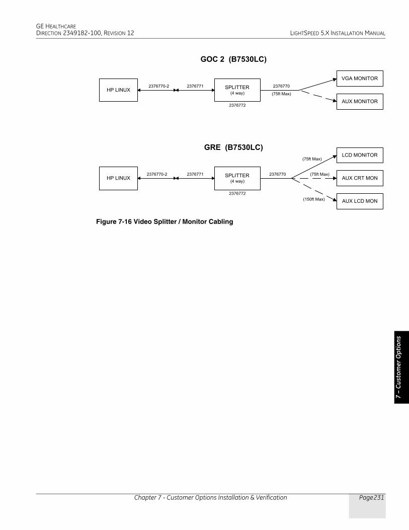
GE HEALTHCAREDIRECTION 2349182-100, REVISION 12 LIGHTSPEED 5.X INSTALLATION MANUAL
Chapter 7 - Customer Options Installation & Verification Page 231
7 –
Cust
omer
Opt
ions
Figure 7-16 Video Splitter / Monitor Cabling
�������������
������
����������
����������
��������� �������
�� !���"�
�������������
�������
�������������
������
�#$�������
����#�������������� ������� �������
�� !���"�
�����������
�������
�����#$����
�� !���"�
��� !���"�
�������

GE HEALTHCAREDIRECTION 2349182-100, REVISION 12 LIGHTSPEED 5.X INSTALLATION MANUAL
Page 232 Section 10.0 - Teleradiology (Framegrabber Type) Systems & Aux. Monitors
10.3 CT Analog Filming Interface Specs (Video & Serial)
Note: The analog (VDB) video output specs and serial interface were specified from, and are the same as, the Genesis interface output specs. This does NOT apply to the digital (LCAM) filming interface.
OUTPUT VALUEamplitude 1 volt peak-to-peak
video 0.643V ± 10%
setup 0.071V ±10%
sync 0.286V ± 10%
DAC resolution 8 bits
diff. linearity ±1 LSB max
glitch area 80 picovolt seconds max, for any step size
rise/fall times > 10 nsec, ± 10-90%
FS settling time 7.5 nsec typical to 1 LSB
transfer function guaranteed monotonic
noise level > 5.0 millivolt peak-t~peak, combined sync/async noise
DC offset ±1 VDC referenced to ground
Table 7-5 Video Output (Measured Into 75Q at BNC Output)
OUTPUT VALUElogic family F series TTL
output low level 0.8VDC max
output high level 2.OVDC mm
output period 41.336 nsecs ±10%
transition times 10 nsec max, ± 10-90%
Table 7-6 Pixel Clock Output
VIDEO TIMING CHARACTERISTIC 60HZ 50 HZpixel frequency 24.192 Mhz 24.192 Mhz
pixel period 41.336 nsec 41.336 nsec
horizontal line frequency 33.6 Khz 33.6 khz
horizontal line width 720 pixels 720 pixels
horizontal active 544 pixels 544 pixels
horizontal blanking 176 pixels 176 pixels
horizontal front porch 26 pixels 26 pixels
Table 7-7 Video Timing Characteristics
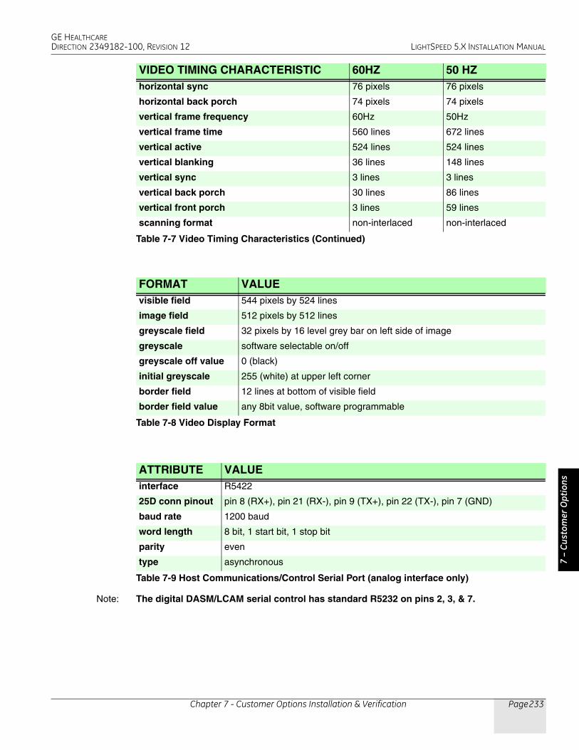
GE HEALTHCAREDIRECTION 2349182-100, REVISION 12 LIGHTSPEED 5.X INSTALLATION MANUAL
Chapter 7 - Customer Options Installation & Verification Page 233
7 –
Cust
omer
Opt
ions
Note: The digital DASM/LCAM serial control has standard R5232 on pins 2, 3, & 7.
horizontal sync 76 pixels 76 pixels
horizontal back porch 74 pixels 74 pixels
vertical frame frequency 60Hz 50Hz
vertical frame time 560 lines 672 lines
vertical active 524 lines 524 lines
vertical blanking 36 lines 148 lines
vertical sync 3 lines 3 lines
vertical back porch 30 lines 86 lines
vertical front porch 3 lines 59 lines
scanning format non-interlaced non-interlaced
FORMAT VALUEvisible field 544 pixels by 524 lines
image field 512 pixels by 512 lines
greyscale field 32 pixels by 16 level grey bar on left side of image
greyscale software selectable on/off
greyscale off value 0 (black)
initial greyscale 255 (white) at upper left corner
border field 12 lines at bottom of visible field
border field value any 8bit value, software programmable
Table 7-8 Video Display Format
ATTRIBUTE VALUEinterface R5422
25D conn pinout pin 8 (RX+), pin 21 (RX-), pin 9 (TX+), pin 22 (TX-), pin 7 (GND)
baud rate 1200 baud
word length 8 bit, 1 start bit, 1 stop bit
parity even
type asynchronous
Table 7-9 Host Communications/Control Serial Port (analog interface only)
VIDEO TIMING CHARACTERISTIC 60HZ 50 HZ
Table 7-7 Video Timing Characteristics (Continued)

GE HEALTHCAREDIRECTION 2349182-100, REVISION 12 LIGHTSPEED 5.X INSTALLATION MANUAL
Page 234 Section 11.0 - Network Connections
Section 11.0Network Connections
BROAD-BANDBroad-band is considered the standard network connection for LightSpeed 5.X. (A dial-up modem is optional.) Broad-band connections should use one of the following Category 5 patch cables:
The CT system is connected to the network through the Console.
• A patch cable (not to exceed 10 feet) should be provided by the customer, and it is used to connect the console to a wall box. (See Notes on Figure 7-17)
• Some customer-site units may require cable duct-work or conduit to route connecting network cables to the workstation, camera and console.
• The run from the hospital switch to the CT wall outlet must not exceed 290 ft. (88m). Bandwidth performance is degraded when the length reaches 300 ft. (91m) or greater.
• For the optional modem: Two phone lines should be provided by the facility. One line is for use with a modem and must be an analog line. The second line is a voice only line.
Figure 7-17 Console Rear Bulkhead
US PROCESS OVERVIEWThe United States network connectivity requirement for this product is broad-band. The US process relies on the Install Specialist to select a Customer Champion and identify an IT contact for the site. Together, those individuals then complete a site assessment to gauge what tasks are needed to fulfill the connection.
Anyone can contact the GE Connectivity team at 800.321.7937, Option #3, with questions.
CAT Num GE Part Num Length
K9000WB 2215028-10 20 m
K9000KP 2215028-5 10 m
K9000JR 2215028-4 5 m
K9000WA 2215028-9 3 m
Table 7-10
To Hospital Network
To Advantage Window if HiSpeed connection is required

GE HEALTHCAREDIRECTION 2349182-100, REVISION 12 LIGHTSPEED 5.X INSTALLATION MANUAL
Chapter 7 - Customer Options Installation & Verification Page 235
7 –
Cust
omer
Opt
ions
CUSTOMER BROAD-BAND RESPONSIBILITIESProvide GE Healthcare Installation Specialist with an accurate site address, telephone number, contact name, and e-mail address for the:
• Customer Champion
- Coordinate VPN activities between Radiology/Cardiology and the Information Technology (IT) departments
- Act as a focal point in assuring site broad-band infrastructure meets GE Healthcare requirements for connection as determined by a mutual assessment with the GE Healthcare Connectivity team.
• IT Contact
- Complete an equipment assessment with GE Healthcare Connectivity team to determine site readiness for broad-band
- Work with the Customer Champion to complete any identified infrastructure changes
- Provide IP addresses for new CT equipment
- Provide a VPN compatible appliance that will support the IPSec tunneling protocol and 3DES data encryption
- To utilize an Internet Service Provider that supports static routing

GE HEALTHCAREDIRECTION 2349182-100, REVISION 12 LIGHTSPEED 5.X INSTALLATION MANUAL
Page 236 Section 11.0 - Network Connections
FE Name:FE Phone:FE Email
Yes No
a) Cisco Pix Firewalls g) Symantec (Raptor) firewallsb) Cisco Routers h) Fireboxc) Cisco 3000 Series (Altiga acquisition) i) Linux S/WAN
j) Sidewinderk) Netscreen
e) Nortel Contivity Software Version 3.2 or higher l) Nonef) Redcreek m) Other ________________________________
Installer e-mail address:
Notes:
Field Engineer needs to provide compatible system informaiton:System ID
If you have questions or need assessment support contact your Zone Champ or:
Joe Gracz - HQ [email protected]
Once you have completed both pages of this form, please send it to:a) Judy Heyer [email protected]) Judy Heyer Fax# 414-918-4707
7. Provide your VPN Installer information, this is the person who will be contacted to schedule the VPN install.
Site Approver's Name
1-262-524-5261
Customer Installer Name:
Gateway Address
Additional System and IP Address Spaces Available on Page 2
IP Address
Installer Telephone Number:
6. Has approval been given to install this VPN connection?
Date:
1. Does your site currently have a persistent (24x7) Internet connection?
2. Is the GEMS Diagnostic Imaging equipment on the Local Area Network and will it be accessible to the Internet?
3. Does your site have a VPN device today?
4. Is the VPN device one of the models below? If Yes , please select the model from the options below.
d) Checkpoint Firewalls Software Version 4.1 and higher
Use the send button on page 2
Remote Service Broadband - Customer Site Assessment
Site Name:City, State:
*If No , the GEMS Connectivity Support Team can help determine device compatibility.
5. Does your VPN device support "triple DES" Encryption?
g GE Medical Systems

GE HEALTHCAREDIRECTION 2349182-100, REVISION 12 LIGHTSPEED 5.X INSTALLATION MANUAL
Chapter 7 - Customer Options Installation & Verification Page 237
7 –
Cust
omer
Opt
ions
MR Software Version CT Software Version
HiSpeed CT/e Minimum 6.0
HiSpeed CT/e dual Minimum 2.06
HiSpeedNX/I Minimum 5.5
LightSpeed QX/I Minimum 1.3
LightSpeed Plus Minimum 2.1Signa TwinSpeed Release 9.0 LightSpeed Ultra Minimum 3Signa Release 9.1 HiSpeed X/ISigna Release 10.x CT/I Minimum 6.2Signa CV/I CNV4 Lxi, Dxi, Fxi, Zxi Minimum 6.01Signa 3TSigna Profile Minimum 7.66Signa Contour Minimum 7.66Magnet Monitor Minimum 2.3 software
Network Products Software Version Nuclear/Pet Software VersionAW 4.0 Version 4.0 or Above Advance Minimum 5.1AW 4.0P eNTEGRA Minimum 2.03
X-Ray Software VersionCardiacINNOVA AllMammographySeno2000D AllDigital RadiologyRevolution XQ/I Version 10.12.5 or aboveRevolution XR/d Version 18.0
MR PSI CT PSIPhilips ACS 1.5T MZP 400 Picker MX-TWIN CZM 400Philips NT 2000 MZP 401 Picker MX 8000 CZM 401Philips NT 3000 MZP 402 Picker PQ CZM 500Philips NT ACS MZP 403 Picker PQ 2000 CZM 501Picker Outlook 0.23T MZM 301 Picker PQ 5000 CZM 502Picker Edge 1.5T MZM 800 Picker PQ 6000 CZM 503Picker Vista 1.0T MZM 801 Picker PQS CZM 504Picker Eclipse 1.5T MZM 900 Siemens AR STAR CZS 100Picker Polaris 1.0T MZM 901 Siemens AR.C CZS 101Siemens Harmony 1.0T MZS 100 Siemens AR.HP CZS 102Siemens Impact 1.0T MZS 200 Siemens AR.SP CZS 103Siemens Impact Expert 1.0T MZS 201 Siemens AR.T CZS 104Siemens SP 1.0T MZS 400 Siemens PLUS-4 EXP CZS 400Siemens SP 1.5T MZS 401 Siemens PLUS-4 POW CZS 401Siemens SP4000 1.5T MZS 403 Siemens PLUS-4 VOL CZS 402Siemens Symhony 1.5T MZS 500Siemens Vision 1.5T MZS 600
Field Engineer needs to provide compatible system informaiton:System ID IP Address
Judy HeyerJudy Heyer 414-918-4707
Gateway Address
Once you have completed this form, please send it to:
Include all Signa(LX, Ovation, OpenSpeed and
CV/I ) MR's System Ids and IP Addresses in
assessment.
Prior to completing an InSite checkout
systems must be upraded to Version 9.0 or 9.1
unless shown in the compatible list below.
System ID List & Compatibility Matrix
Multi Vendor
Send Now
g GE Medical Systems

GE HEALTHCAREDIRECTION 2349182-100, REVISION 12 LIGHTSPEED 5.X INSTALLATION MANUAL
Page 238 Section 11.0 - Network Connections
Figure 7-18 LightSpeed System Interconnection Runs
TO POWERSOURCE
GANTRY(CT2)
TABLE(CT1)
OPERATORS CONSOLE/COMPUTER(OC1)
PM(PDU)
WL
1
SEO A13
4
TOETHERNETBroadband Network
(see Note 3)
2
Laser Imager Option(see Note 2)
DS
Only one phone connectionis required for the system.
5
10
OPTION
KEY:
TO TELEPHONE
SYSTEM(see Note 1)
NOTES:
1) Used for remote diagnostics - Option
2) Refer to the appropriate Pre-installation / Installation documents for the Laser Camera
3) Category 5 cable. Use one of the following patch cords:
CAT Num GE Part Num Length
K9000WB 2215028-10 20 m K9000KP 2215028-5 10 m K9000JR 2215028-4 5 m K9000WA 2215028-9 3 m
GE HEALTHCAREDIRECTION 2349182-100, REVISION 12 LIGHTSPEED 5.X INSTALLATION MANUAL
Chapter 8 - Patient Touch Leakage Test Page 239
8 –
Leak
age
test
Chapter 8Patient Touch Leakage Test
Section 1.0Personnel Requirements
Section 2.0Overview
This procedure must be completed after all options have been installed. It covers three safety and leakage current checks:
• Patient Touch current test (completed after installation)
• System Ground resistance measurement (completed during installation)
• Ground current typical (completed after installation - optional)
Section 3.0Preliminary Requirements
3.1 Tools and Test Equipment
3.2 Safety
WARNING POTENTIAL FOR SHOCK GROUND WIRES WILL HAVE GROUND CURRENT PRESENT WITH POWER “ON”. FOLLOW APPROPRIATE SAFETY PROCEDURES FOR WORKING WITH AN ENERGIZED SYSTEM.
NOTICE Follow ALL required safety and PPE procedures customary for your organization, when working on this product.
Required Persons Preliminary Reqs Procedure Finalization
1 10 mins 20 mins 10 mins
Item Qty
Standard service tool kit 1
Dale 600 Meter (from Tool Pool) 1
Dale extended length leads 1

GE HEALTHCAREDIRECTION 2349182-100, REVISION 12 LIGHTSPEED 5.X INSTALLATION MANUAL
Page 240 Section 4.0 - Procedure
3.3 Required Conditions
• Only trained service personnel should service the GE CT Scanner.
• Footswitch cover must be removed.
Section 4.0Procedure
4.1 Patient Touch Leakage Current Test Procedure
1.) Move the table to ISO elevation.
2.) Remove the footswitch covers and the gantry left side cover.
3.) Refer to the Dale 601 Operator’s Manual for instructions on the use of the Dale 600 meter for measuring leakage current (or refer to Figure 8-1, for a quick overview)
Figure 8-1 Using Dale 600 to Measure Leakage Current
4.) Plug the Dale 600 Meter into the outlet on the gantry left side. Confirm the outlet is correctly wired per the three LED indicators on the meter.

GE HEALTHCAREDIRECTION 2349182-100, REVISION 12 LIGHTSPEED 5.X INSTALLATION MANUAL
Chapter 8 - Patient Touch Leakage Test Page 241
8 –
Leak
age
test
5.) Connect one end of the shorter black lead to the chassis plug and connect the other end to the table ground bus.
6.) Connect the longer red test lead (or the longer black lead) to the external plug on the top of the Dale 600 meter.
7.) Set the function switch on the Dale to external. Use the external lead to touch the meter’s test terminal, to test that the meter is operational.
8.) The black lead will be connected to the table base ground bus, and the read lead will be connected to the devices (components) under test.
Note: Your meter may have two black leads that are keyed for chassis and the ground connection.
A valid calibration sticker must be present on the meter used. Record this information on the GE 4879 form.
9.) Beware: Leakage current cannot exceed the following and is tested with power ON:
a.) Critical care areas (invasive) - 10µa CT Systems
b.) General care areas - 20µa
c.) Not intended for patient area - 50µa
10.) Testing must be completed between the system reference ground point (table base) to unit reference ground points (i.e. gantry and table, see Figure 8-3).
11.) Test all conductive surfaces and components within patient reach or within 6 feet (1.9m) of the table and 7.5 feet (2.3m) above.
- Measure at table maximum travels.
- At some sites, wall outlet cover plates and sinks may become an issue.
12.) Test all Optional components such as in-room monitors, injector, overhead monitor suspensions, and table options.
Record these results in the data sheet. To be completed at install and during PM inspections.
13.) Test conditions:
a.) Table max elevation Min - Max travel
b.) Patient face up and face down head first feet first
c.) Table min elevation 7.2’ patient access to all conductive surfaces including:
* IV poles and tray assembly* any smart step monitors and stands* table bearing rails * all other conductive surfaces
NOTICE Be Aware of Static Discharge from: scan window, keypads, display, and touch pads or other plastic surfaces.
Gnd Bus to Install <10µAAny table ground points within the 6’ rangeAny gantry ground points within the 6’ rangeInjector assembly metal surfaceBoom-in-Room metal surfaceMonitors or metal surfaceSink or metal surfaceInstalled table accessories(other)(other)(other)

GE HEALTHCAREDIRECTION 2349182-100, REVISION 12 LIGHTSPEED 5.X INSTALLATION MANUAL
Page 242 Section 4.0 - Procedure
14.) Procedure Hints:
a.) Look for items that have abnormal measurements, high or low.
These could indicate mis-wiring, loose connections, or poor connections due to corrosion, painted surfaces, etc.
b.) High leakage could indicate a wiring error such as a neutral connected to the ground.
c.) Fluctuating ground currents could indicate a short, poor connection, or facilities ground problem causing leakage currents from other areas of the facility to flow though our system grounds.
d.) Refer to the illustrations below, for measurement visual descriptions.
Figure 8-2 CT Leakage Current Map
Figure 8-3 Measurement Points

GE HEALTHCAREDIRECTION 2349182-100, REVISION 12 LIGHTSPEED 5.X INSTALLATION MANUAL
Chapter 8 - Patient Touch Leakage Test Page 243
8 –
Leak
age
test
4.2 Ground Resistance Checks Procedure (done during mechanical install)
Refer to the procedures found in Book 1, Chapter 3:
• Section 1.0 - System Continuity & Ground Checks (Mechanical Contractor)
• Section 2.0 - Site Ground Continuity Check
Section 5.0Finalization
No finalization required.

GE HEALTHCAREDIRECTION 2349182-100, REVISION 12 LIGHTSPEED 5.X INSTALLATION MANUAL
Page 244 Section 5.0 - Finalization
End of Chapter.

GE HEALTHCAREDIRECTION 2349182-100, REVISION 12 LIGHTSPEED 5.X INSTALLATION MANUAL
Chapter 9 - Forms and Checklists Page 245
9 –
Form
s
Chapter 9Forms and Checklists
This chapter includes the following sections:
• Section 1.0 - Mechanical Vendor Installation List
• Section 2.0 - Electrical Calibration Installation Checklist
• Section 3.0 - GE Form 4879 Installation Data Verification
• Section 4.0 - Install Completion Checklist
• Section 5.0 - Electronic Forms

GE HEALTHCAREDIRECTION 2349182-100, REVISION 12 LIGHTSPEED 5.X INSTALLATION MANUAL
Page 246 -
This page intentionally left blank

GE HEALTHCAREDIRECTION 2349182-100, REVISION 12 LIGHTSPEED 5.X INSTALLATION MANUAL
Chapter 9 - Forms and Checklists Page 247
9 –
Form
s
Section 1.0Mechanical Vendor Installation List
Vendor Company NameInstall Trained
GE FE Yes
MId-West No
Jentree Somewhat
Revels
AMS Install Start Date ______________
AK Associates
All Others Install Completion Date ______________
Hours Spent ______Number of Trips _______FDO _________
CLEAN UP
Move Customer boxes to one corner or counter.
Place Field Engineer Material (phantoms, hoist, kits, tools) into the service cabinet.
Put all documentation (including software, HHS doc) in the purple box and leave by the console.
REMOVE TRASH
Remove and recycle cardboard as required.
Place skids and wood into the dumpster.
RETURN DOLLIES (USA ONLY)
Check the packing list found in the purple box for dolly return location.
DO NOT return the console shipping skid to Milwaukee.
INSTALL COVERS
Recheck Gantry and Table anchor for 75ft-lb.
Install PDU covers.
Install table foot-switch assembly and covers as required in your area.
Install console covers and align as needed for proper cover fit.
Install gantry base covers, and rear cable box cover as required.
CLEAN THE EQUIPMENT
Use the cleaning supplies in the installation support kit to clean the equipment.
TOUCH UP NICKS
Use the paint supplies found in the installation support kit to touch up nicks in the equipment.

GE HEALTHCAREDIRECTION 2349182-100, REVISION 12 LIGHTSPEED 5.X INSTALLATION MANUAL
Page 248 Section 1.0 - Mechanical Vendor Installation List
COMPLETE PAPERWORK
Collect all Product Locators and store in purple box.
Complete the Field Engineer sign-off procedure with FE.
Complete and sign this list.
SIGNATURELead Mechanical Installer __________________________________
Field Engineer _____________________________________
Mechanical Vendor installation comments ________________________________________
_____________________________________________________________________________
_____________________________________________________________________________
_____________________________________________________________________________
Short shipped? Yes No
Correct Documentation? Yes No Missing
Equipment Inventory Process OK - Found all items
Items in different boxes
Open all boxes to find
Couldn’t find all items
Field Engineer comments ______________________________________________________
_____________________________________________________________________________
_____________________________________________________________________________
_____________________________________________________________________________
Return to: [email protected] Service Engineering
[email protected] Project Leader, Installation Services
ELECTRONIC VERSION OF THIS FORMAn electronic version of this form is available. Use of the form requires Microsoft® Word. To complete and submit this form electronically, see Section 5.0 - Electronic Forms.
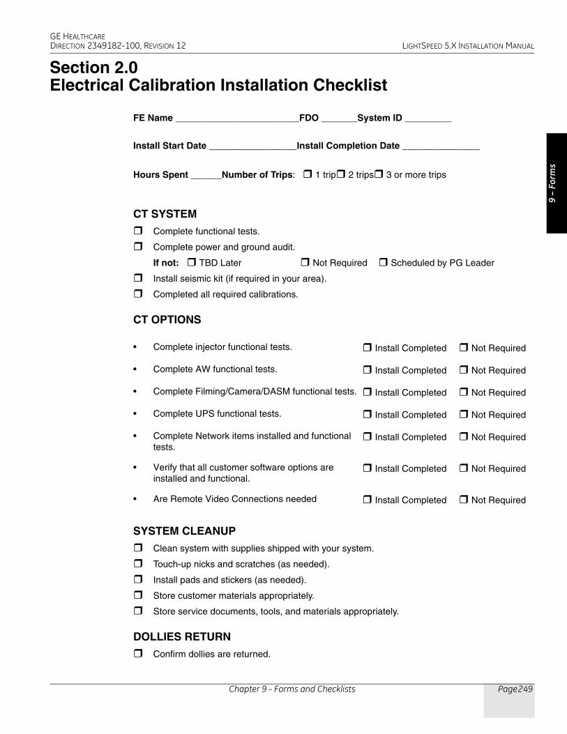
GE HEALTHCAREDIRECTION 2349182-100, REVISION 12 LIGHTSPEED 5.X INSTALLATION MANUAL
Chapter 9 - Forms and Checklists Page 249
9 –
Form
s
Section 2.0Electrical Calibration Installation Checklist
FE Name ________________________FDO _______System ID _________
Install Start Date _________________Install Completion Date _______________
Hours Spent ______Number of Trips: 1 trip 2 trips 3 or more trips
CT SYSTEM
Complete functional tests.
Complete power and ground audit.
If not: TBD Later Not Required Scheduled by PG Leader
Install seismic kit (if required in your area).
Completed all required calibrations.
CT OPTIONS
SYSTEM CLEANUP
Clean system with supplies shipped with your system.
Touch-up nicks and scratches (as needed).
Install pads and stickers (as needed).
Store customer materials appropriately.
Store service documents, tools, and materials appropriately.
DOLLIES RETURN
Confirm dollies are returned.
• Complete injector functional tests. Install Completed Not Required
• Complete AW functional tests. Install Completed Not Required
• Complete Filming/Camera/DASM functional tests. Install Completed Not Required
• Complete UPS functional tests. Install Completed Not Required
• Complete Network items installed and functional tests.
Install Completed Not Required
• Verify that all customer software options are installed and functional.
Install Completed Not Required
• Are Remote Video Connections needed Install Completed Not Required

GE HEALTHCAREDIRECTION 2349182-100, REVISION 12 LIGHTSPEED 5.X INSTALLATION MANUAL
Page 250 Section 2.0 - Electrical Calibration Installation Checklist
INSTALL COMPLETION MATERIAL CHECKS
All HHS documentation completed.
Write Install related CQAs as needed.
Complete all dispatching activities (03-04-10 codes).
Complete customer acceptance checks/test.
Complete system transfer and notify appropriate GE personnel.
Communicate with the customer and address installation issues.
SIGNATUREField Engineer _____________________________________
Field Installation Comments / Issues _____________________________________________
_____________________________________________________________________________
_____________________________________________________________________________
_____________________________________________________________________________
Alignment Calibration Required? Yes No
Correct Documentation Shipped? Yes No Missing
Return to: [email protected] Service Engineering
ELECTRONIC VERSION OF THIS FORMAn electronic version of this form is available. Use of the form requires Microsoft® Word. To complete and submit this form electronically, see Section 5.0 - Electronic Forms.

GE HEALTHCAREDIRECTION 2349182-100, REVISION 12 LIGHTSPEED 5.X INSTALLATION MANUAL
Chapter 9 - Forms and Checklists Page 251
9 –
Form
s
Section 3.0GE Form 4879 Installation Data Verification
NOTICE Only use the Installation manual that arrives with your system for installation. Any other revisions of this manual may not exactly match your system.
3.1 Installation Site History
3.1.1 RECORDS KEEPING AND DOCUMENTATION - IMPORTANT!• Locate the HHS data, sent from the factory, in the software collector box.
• Retain a copy of this HHS data and the data collected at the site, on site in the service cabinet.
• All sites that are required to submit an FDA 2579 form, must send a copy of all HHS test information to the HHS administrator along with a completed GE 4879 and FDA 2579 form. This applies to both GEE and Local FE's who complete 5.X installations.
• A generator RECAL is not required on 5.X installations unless a certified component is replaced.
• If any one of the calibration procedures fail, data collected is different, or you replace any
• Certified component in the High Voltage section, YOU MUST RECALIBRATE THE SYSTEM.
• To recalibrate the system, refer to procedures in the System Service manual.
• Complete all installation check list items, as proof the procedure was completed.
3.1.2 Component Tractability - IMPORTANT!• Complete the Product Locator Report and mail it. Retain a copy on site with the HHS data records.
• Retain any additional information, per your local LCT procedures.
Completed By:GE Energy Healthcare FEOther
Date:______________________
Name: ___________________________________________
3.1.3 Installation Procedures Traceability - IMPORTANT!
Procedure Completed By (Circle One)
TestDate
Name (Print)
Mechanical ProceduresBook 1
GE EnergyHealthcare FE
Electrical Procedures Book 2
GE EnergyHealthcare FE
IQ & Quality ProceduresBook 2
GE EnergyHealthcare FE
GE 4879 GE EnergyHealthcare FE
GE 4879 GE EnergyHealthcare FE
FDA e-2579 GE EnergyHealthcare FE

GE HEALTHCAREDIRECTION 2349182-100, REVISION 12 LIGHTSPEED 5.X INSTALLATION MANUAL
Page 252 Section 3.0 - GE Form 4879 Installation Data Verification
3.1.4 Installation Test & Tools Traceability - IMPORTANT!
3.2 System X-Ray Indicators and Warning Labels
3.2.1 X-Ray On Indicators
1.) Perform several scans.
2.) Verify that the X-ray ON lights are on during the scans.
3.) Use a mirror to check the x-ray indicator light on the gantry rear cover
FDA e-2579 GE EnergyHealthcare FE
Procedure Completed By (Circle One)
TestDate
Name (Print)
Where Installed
City State
Customer's Telephone Number Room No.
System ID # GON #
Master Control - Console
Model # Serial #
Gantry
Model # Serial #
Installation Completion Date
Test Equipment History
DVM Manufacturer DVM Model #
DVM Serial # Cal Due Date
Leakage Meter Manufacturer Model #
Serial # Cal Due Date
Amp Meter Manufacturer Model #
Serial # Cal Due Date
Other - Manufacturer Model #
Serial # Cal Due Date

GE HEALTHCAREDIRECTION 2349182-100, REVISION 12 LIGHTSPEED 5.X INSTALLATION MANUAL
Chapter 9 - Forms and Checklists Page 253
9 –
Form
s
3.2.2 Operator Indicators - HHS Requirement
Initials: Date:
X-Ray Indicators on the SCIM, Front and Back of Gantry Illuminate During X-Ray.
3.3 Warning Labels
3.3.1 Laser Warning labels
1.) Laser warning labels appear on the gantry lower right corner near the floor, and near each of the laser window opening on the gantry cover
2.) Obtain and install all warning labels in the appropriate language for the country installed.
Initials: Date:
All laser warning labels are present.
3.3.2 Operator Use Warning Label - SCIMMake sure the X-Ray warning label appears in the correct location on the SCIM.
Initials: Date:
Warning labels are present.
LIGHTS ON LIGHT LOCATIONSSCIM
Gantry Front
Gantry Rear
Room Warning Light

GE HEALTHCAREDIRECTION 2349182-100, REVISION 12 LIGHTSPEED 5.X INSTALLATION MANUAL
Page 254 Section 3.0 - GE Form 4879 Installation Data Verification
3.3.3 Appropriate Language Warning Labels VerificationCheck that all indicators, cautions and warning labels have been installed per the procedure in CT installation book 2, Chapter 5 Section 3.4.
Initials: Date:
All Appropriate Language indicators, cautions and warning labels are installed.
3.4 Tomographic Plane Indication Accuracy
1.) Record the scan location (shown on the image annotation) of the image with the darkest scan plane indicator (darkest long bar).
2.) If your system meets all the installation and alignment specifications, the image at scan location zero (S0.0) should contain the scan plane indicator.
Specification:
If scan location S1.0 or scan location I1.0 has the darkest bar, the system still meets the specification. The scan plane deviation should equal S0.0 +1.0mm.
Repair: If necessary, adjust the internal alignment light position to meet the S0.0 +1.0mm requirement.
Initials: Date:
Tomographic plane indicator accuracy passed.
3.5 Table/Gantry Alignment Procedure
Repeat this procedure until the table edges line up (± 1mm). If needed, a scout can be completed to check table horizontal presentation.
Check the two scout scans.
Specifications:
Molding strips should be parallel within +/- 3 mm. Cradle should be level within ± 1 mm.
Repair:
Repeat table to gantry alignment, and repeat scan test.
(Must be within +/- 1mm)
LANDMARK DARKEST BAR LOCATION DATA Internal
External

GE HEALTHCAREDIRECTION 2349182-100, REVISION 12 LIGHTSPEED 5.X INSTALLATION MANUAL
Chapter 9 - Forms and Checklists Page 255
9 –
Form
s
Tighten the anchors and torque to 74.6 N-m (55 ft.-lb.).
Contractor Anchored Systems
Initials: Date:
Table cradle alignment accuracy passed.
3.6 Check Alignment Lights - Test
Internal Axial Lights
External Axial Lights
Coronal Lights
Initials: Date:
Table cradle alignment Light accuracy passed.
3.7 Interference Test
Interference Test Requirement:
No tilt motion shall cause the gantry tilting frame to touch the stationary base covers for any tilt angle.
Initials: Date:
All interference tests were completed and all tests passed.
CRADLE LEVEL DATA PASSAcross Cradle
Length of Cradle
CRADLE ALIGNMENTCradle Front min length Edge to edge
Cradle Rear max length Edge to edge
Cradle Center From cradle CL
Gantry Completed Table Completed
8" Hilti QB 8" Hilti QB
Contractor name
Anchor type
Meets

GE HEALTHCAREDIRECTION 2349182-100, REVISION 12 LIGHTSPEED 5.X INSTALLATION MANUAL
Page 256 Section 3.0 - GE Form 4879 Installation Data Verification
3.8 System Functional Test
Use the system tests in the following sections to exercise all aspects of the system and to ensure system integrity before releasing to the customer.
Initials: Date:
All functional tests were completed and all tests passed.
3.9 IQ Section - 5.X Image Quality Series
Complete the image series listed in Chapter 6, and record the values in the site installation manual.
Note: IQ Sections may be slightly different for RT, Pro16, LS16, Ultra and Plus systems.
3.10 Documentation Section - System Paperwork & Product Locator
3.10.1 Installation VerificationCopy or submit e-copied of these documents to the HHS administrator. Leave a copy on site as a record of system installation and test completion.
Mechanical Installation Completion Form
To be completed by the mechanical installation team leader GEE or FE
Electrical Installation Completion Form
To be completed by the electrical installation team leader GEE or FE
GE 4879 Data Sheets
Note: More than one form may be submitted for the same installation by the different installation teams. (For GEE completed work and FE completed work)
To be completed by the installation team leader. All parts that was completed.
A separate GE 4879 will be completed when the Image Quality testing is completed. This document is sent to the HHS administrator.
GE Manufacturing HHS Data Sheets
Complete and copy by the installation team leader These document are sent with this data form to the HHS administrator.
GE Shipped Documentation
All shipped documentation was received.
Customer Documentation
FE Documentation
3.10.2 Product Locator
Cards
Collect and update product locator.
Leave a copy or one of the cards on site
GE HEALTHCAREDIRECTION 2349182-100, REVISION 12 LIGHTSPEED 5.X INSTALLATION MANUAL
Chapter 9 - Forms and Checklists Page 257
9 –
Form
s
3.10.3 Regulatory Information Distribution
Document Distribution
1.) A copy of all items from section 1 above
2.) A copy of all items from section 2 above
3.) Mail to HHS administrator
HHS FDA 2579
Note: More than one form may be submitted for the same installation by the different installation teams. (GEE completed work and FE completed work)
1.) Complete the FDA e-2579
2.) When completed submit to HHS administration. Correct all errors. Do Not print this form. A printable version will be sent to you from HHS administration for your records.
3.) Some states require a State Registration Number to complete this form. If you have questions concerning your state, contact the HHS administrator.

GE HEALTHCAREDIRECTION 2349182-100, REVISION 12 LIGHTSPEED 5.X INSTALLATION MANUAL
Page 258 Section 3.0 - GE Form 4879 Installation Data Verification
This page intentionally left blank

GE HEALTHCAREDIRECTION 2349182-100, REVISION 12 LIGHTSPEED 5.X INSTALLATION MANUAL
Chapter 9 - Forms and Checklists Page 259
9 –
Form
s
Section 4.0Install Completion Checklist
4.1 CT System
Functional tests completed.
Power and ground audit completed.
Seismic kit installed (if needed in your area).
4.2 CT Options
Injector functional tests completed.
AWW functional tests completed.
Filming/Camera/DASM functional tests completed.
UPS functional tests completed.
Network items installed and functional tests completed.
Verify that all customer software options are installed and functional.
Teleradiology Connections (Refer to Section 10.0 on page 230)
4.3 System Cleanup
Clean system with supplies shipped with your system.
Touch-up nicks and scratches (as needed).
Install pads and stickers (as needed).Specifically for LS16, Ultra & Plus, replace the caution labels (two) on the table frame withappropriate language labels from the 2199652 label set, as needed. The table comes withthe labels shown as:
Store customer materials appropriately.
Store service documents, tools, and materials appropriately.
4.4 Dollies Return
Console is shipped on a pallet. Do Not return pallet to GE Healthcare.

GE HEALTHCAREDIRECTION 2349182-100, REVISION 12 LIGHTSPEED 5.X INSTALLATION MANUAL
Page 260 Section 4.0 - Install Completion Checklist
4.5 Install Completion Material Checks
Complete all HHS documentation. Complete Install CQAs as needed.
Complete all dispatching activities (03-04-10 codes).
Complete customer acceptance checks/test.
Complete system transfer and notify appropriate GE personnel.
Communicate with the customer and address installation issues.

GE HEALTHCAREDIRECTION 2349182-100, REVISION 12 LIGHTSPEED 5.X INSTALLATION MANUAL
Chapter 9 - Forms and Checklists Page 261
9 –
Form
s
Section 5.0Electronic Forms
Several of the forms in this chapter may be completed and submitted electronically by following the procedure described below.
1.) To select and open the desired form, click on the appropriate link below. Either Microsoft® Word or Excel will launch, depending upon the type of form.
a.) Microsoft® Word documents:
* Mechanical Vendor Installation List
* Electrical Calibration Installation Checklist
b.) Microsoft® Excel spreadsheet:
* HHS Data Sheet
2.) A warning box similar to the samples below may appear. Click YES or OPEN as appropriate.
3.) Complete the form (TAB to move between fields).
NOTICE Be certain to save a copy to a local hard drive.
4.) Submit the form, by choosing FILE > SEND TO > MAIL RECIPIENT. Enter the e-mail addresse(s) shown at the end of the signature section of the form in the Send To field.

GE HEALTHCAREDIRECTION 2349182-100, REVISION 12 LIGHTSPEED 5.X INSTALLATION MANUAL
Page 262 Section 5.0 - Electronic Forms
End of Chapter.

GE HEALTHCAREDIRECTION 2349182-100, REVISION 12 LIGHTSPEED 5.X INSTALLATION MANUAL
Appendix E – Additional Characterization Procedures Page 263
E - A
ddt’l
Cha
r.
AppendixEAdditional Characterization Procedures
For information related to alignment, setup, and calibration procedures, please refer to the appropriate LightSpeed 5.X Service Methods publication.

GE HEALTHCAREDIRECTION 2349182-100, REVISION 12 LIGHTSPEED 5.X INSTALLATION MANUAL
Page 264 Appendix E – Additional Characterization Procedures
End of Appendix.

GE HEALTHCAREDIRECTION 2349182-100, REVISION 12 LIGHTSPEED 5.X INSTALLATION MANUAL
Appendix F – System Configuration Data Sheets Page 265
F - C
onfig
Dat
a Sh
eets
AppendixFSystem Configuration Data Sheets
REQUIREMENTRecord valuable system information in the data sheets that follow. Consult with your customer or network administrator to obtain the information. Understanding how the customer plans to use their CT scanner, and their network and filming expectation reduces the time required to reconfigure the system.
• Table F-1 Manual Film Composer Options, on page 265
• Table F-2 System Network Configuration, on page 265
• Table F-3 Networking Application (Image transfer) Configuration, on page 266
• Table F-4 DASM Laser Camera Configuration, on page 267
• Table F-5 DICOM Print Camera Configuration, on page 267
• Table F-6 DICOM Print Camera Advanced Configuration, on page 268
MANUAL FILM COMPOSER OPTIONS
SYSTEM NETWORK CONFIGURATION
MANUAL FILM COMPOSER OPTIONSSlide Format (if available):
Greyscale:
Auto Printing:
Auto Clear Page:
Icon Labels:
Expose Order:
No. of Copies:
Table F-1 Manual Film Composer Options
SYSTEM NETWORK CONFIGURATION
FIELD NAME: SETENV NAME: FIELD VALUE:System Settings: Service ID SERVICE_ID
Hospital Name HOSPITAL_NAME
Exam Number * * ask customer or checklog
DAS Type DASTYPE
PDU Type PDUTYPE
Network Settings: Gateway Host Name GATEWAY_HOSTNAME
Gateway IP GATEWAY_IP
Table F-2 System Network Configuration

GE HEALTHCAREDIRECTION 2349182-100, REVISION 12 LIGHTSPEED 5.X INSTALLATION MANUAL
Page 266 -
NETWORK APPLICATION (IMAGE TRANSFER) CONFIGURATIONRecord the network application (image transfer) configuration.
HOST ETHERNET ADDRESS
_________:_________:_________:_________:_________:_________
Gateway Net Mask GATEWAY_NETMASK
Gateway Broadcast Mask
GATEWAY_BROADCAST
Suite Name SUITEID
Option Network Printer IP Address
Option HIS Server IP Address
Option HIS Server AE Title
Option HIS server AE Port
Option CT Server AE Title
Option Connect Pro IP Address
NETWORKING APPLICATION (IMAGE TRANSFER) CONFIGURATION
AE TITLE OR HOST NAME
NETWORK ADDRESS
NETWORK PROTOCOL
PORT NUMBER
COMMENTS
Table F-3 Networking Application (Image transfer) Configuration
SYSTEM NETWORK CONFIGURATION
FIELD NAME: SETENV NAME: FIELD VALUE:
Table F-2 System Network Configuration (Continued)

GE HEALTHCAREDIRECTION 2349182-100, REVISION 12 LIGHTSPEED 5.X INSTALLATION MANUAL
Appendix F – System Configuration Data Sheets Page 267
F - C
onfig
Dat
a Sh
eets
CAMERA APPLICATION CONFIGURATIONRecord the camera application configuration for the DASM or DICOM print camera.
DASM LASER CAMERA CONFIGURATIONCamera Type:
DASM Type:
Film Smooth/Sharp Setting:
Options:
Valid Film Formats:
Default Film Formats:
Table F-4 DASM Laser Camera Configuration
DICOM PRINT CAMERA CONFIGURATIONCamera Type:
Host Name:
IP Address:
AE Title:
TCP/IP Listen Port:
Comments (Optional):
Valid Film Formats:
Default Film Formats:
Destination:
Orientation:
Medium Type:
Magnification Type:
Table F-5 DICOM Print Camera Configuration

GE HEALTHCAREDIRECTION 2349182-100, REVISION 12 LIGHTSPEED 5.X INSTALLATION MANUAL
Page 268 -
CONFIGURATIONNote: Type the text shown in boldface, and press the ENTER key on the keyboard.
NEXT STEPSResume installation following instructions in Chapter 5: Restore System State (Section 2.3).
DICOM PRINT CAMERA ADVANCE CONFIGURATIONSmoothing Type:
Configuration:
Minimum Density:
Maximum Density:
Empty Density:
Border Density:
Association Timeout:
Session Timeout:
N-Set Timeout:
N-Action Timeout:
N-Create Timeout:
N-Delete Timeout:
N-Get Timeout:
Table F-6 DICOM Print Camera Advanced Configuration
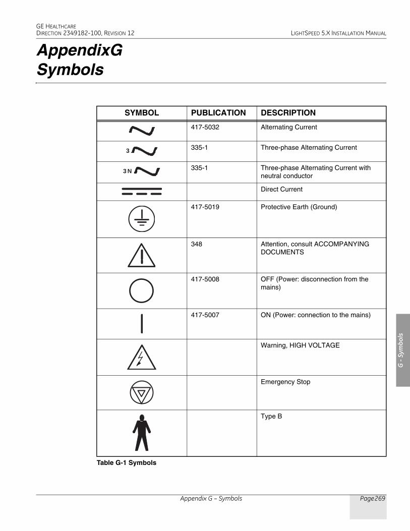
GE HEALTHCAREDIRECTION 2349182-100, REVISION 12 LIGHTSPEED 5.X INSTALLATION MANUAL
Appendix G – Symbols Page 269
G -
Sym
bols
AppendixGSymbols
SYMBOL PUBLICATION DESCRIPTION
417-5032 Alternating Current
335-1 Three-phase Alternating Current
335-1 Three-phase Alternating Current with neutral conductor
Direct Current
417-5019 Protective Earth (Ground)
348 Attention, consult ACCOMPANYING DOCUMENTS
417-5008 OFF (Power: disconnection from the mains)
417-5007 ON (Power: connection to the mains)
Warning, HIGH VOLTAGE
Emergency Stop
Type B
Table G-1 Symbols
3
N 3

GE HEALTHCAREDIRECTION 2349182-100, REVISION 12 LIGHTSPEED 5.X INSTALLATION MANUAL
Page 270 Appendix G – Symbols
417-5339 X-ray Source Assembly Emitting
417-5009 Standby
Start
Table Set
Abort
Intercom
(on Operator Console)Power On: light onStandby: light off
SYMBOL PUBLICATION DESCRIPTION
Table G-1 Symbols

CT

272
© 2003-2006, General Electric Company.GE Medical Systems, a General Electric Company, going to market as GE Healthcare.3000 N. Grandview BoulevardWaukesha, Wisconsin 53188USA
www.gehealthcare.com