Embed Size (px)
Citation preview
Lightning Protection Systems
ATLAS Enquiry Cases
Introduction
The following enquiry cases have been received by the ATLAS Lightning Protection Committee regarding the interpretation of BS EN 62305, the recognised British Standard for the design, installation and testing of lightning protection systems.
Please note that any advice is given in good faith with the aim of providing general guidance on best practice. ATLAS and the individuals and organisations responsible for the advice do not accept any liability arising in any way from relying on it. If you require advice on a specific issue, you should seek your own independent professional advice.
Contents
1. Under Tiles Systems Page 3
2. Type B Earthing System Page 4
3. Reinforcing Earthing Page 5
4. Metal Roof Thickness Page 6
5. Frequency of Testing Page 7
6. Ridge Conductor Page 8
7. Thermal Effects Page 9
8. Jointing Compound Page 10
9. Metal Under Non-Conducting Roof Page 11
10. Testing of Structural Reinforcing Page 12
11. Bonding Structural Steel Columns Page 13
12. Type “B” Earth in Service Trench Page 14
13. Plant – Power Cable on Roof Page 15
14. Plant – Insufficient Roof Thickness Page 16
15. Protection of Temporary Structures Page 17
16. Equipotential Bonds to Lifts and Services Page 18
17. ESE and UK Standards Page 19
18. Use of TEK Screws for Bonding Page 20
19. Continuity of RI-Steelwork when used as Down Conductors Page 21
20. Reference Earth Electrodes Page 22
21. Use of Metal Guttering in Air Termination Systems Page 23
2
22. Use of Re-bars in Structural Reinforcing as the Down Conductor Page 24
23. Cross Bonding Internal Columns with the Earth Termination System Page 25
24. Retrospective installation of lightning conductor fixings to existing tiled / slate
roofs using standard slateholdfasts
Page 26
25. Using BS 6651 as a Reference Standard Page 27
26. Bonding of Solar Panels Page 28
27. Lightning Protection for Scaffolding Page 29
28. Earth Rod Resistance Values Page 30
29. Down Conductors – Cavity Walls Page 31
3
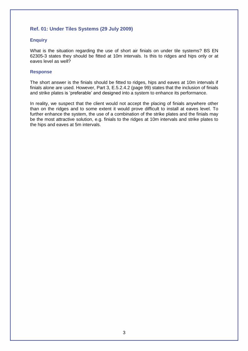
Ref. 01: Under Tiles Systems (29 July 2009) Enquiry What is the situation regarding the use of short air finials on under tile systems? BS EN 62305-3 states they should be fitted at 10m intervals. Is this to ridges and hips only or at eaves level as well? Response The short answer is the finials should be fitted to ridges, hips and eaves at 10m intervals if finials alone are used. However, Part 3, E.5.2.4.2 (page 99) states that the inclusion of finials and strike plates is ‘preferable’ and designed into a system to enhance its performance. In reality, we suspect that the client would not accept the placing of finials anywhere other than on the ridges and to some extent it would prove difficult to install at eaves level. To further enhance the system, the use of a combination of the strike plates and the finials may be the most attractive solution, e.g. finials to the ridges at 10m intervals and strike plates to the hips and eaves at 5m intervals.
4
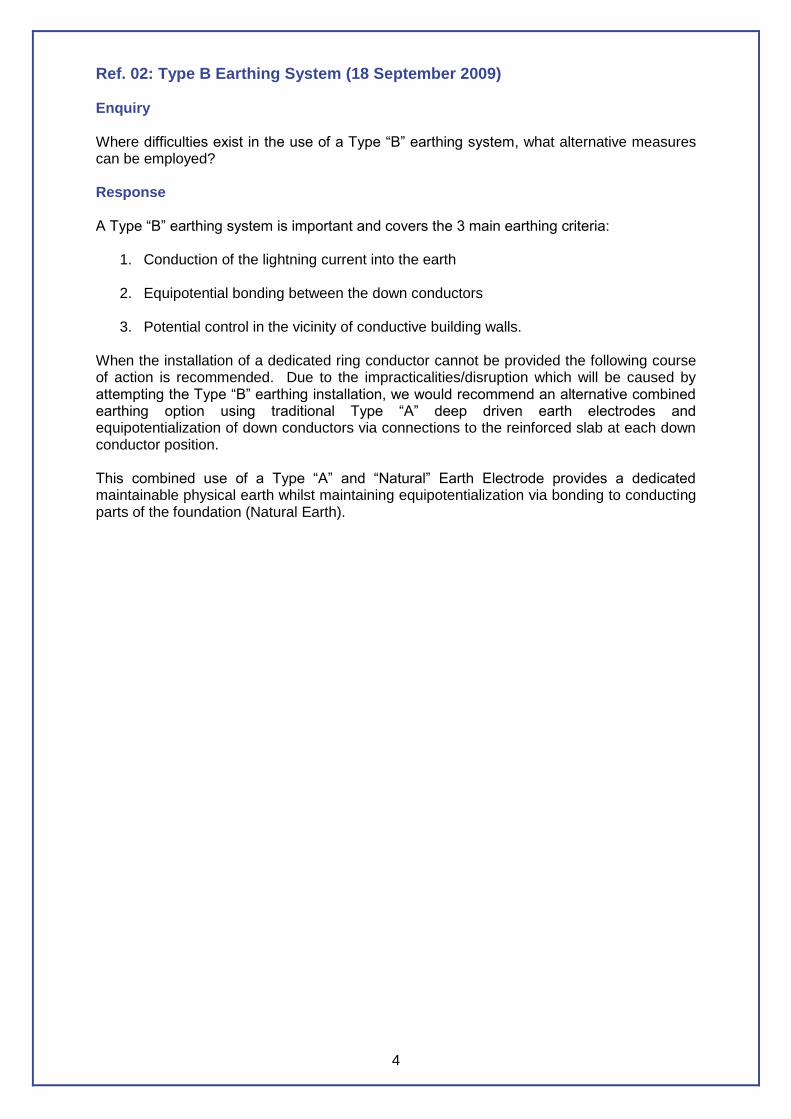
Ref. 02: Type B Earthing System (18 September 2009) Enquiry Where difficulties exist in the use of a Type “B” earthing system, what alternative measures can be employed? Response A Type “B” earthing system is important and covers the 3 main earthing criteria:
1. Conduction of the lightning current into the earth
2. Equipotential bonding between the down conductors
3. Potential control in the vicinity of conductive building walls. When the installation of a dedicated ring conductor cannot be provided the following course of action is recommended. Due to the impracticalities/disruption which will be caused by attempting the Type “B” earthing installation, we would recommend an alternative combined earthing option using traditional Type “A” deep driven earth electrodes and equipotentialization of down conductors via connections to the reinforced slab at each down conductor position. This combined use of a Type “A” and “Natural” Earth Electrode provides a dedicated maintainable physical earth whilst maintaining equipotentialization via bonding to conducting parts of the foundation (Natural Earth).
5
Ref. 03: Reinforcing Earthing (25 September 2009) Enquiry In terms of additional conductors laid over a reinforced slab:
1. Do you have to clamp the additional conductor to the reinforcing?
2. How often should this clamping occur?
It is our view that the additional conductor should be clamped to the reinforcing at each down conductor position relative to the design level i.e. 10m, 15m, and 20m and for structures containing electronic equipment this bonding will be at 5m spacings as per clause E.6.2.5 Paragraph 10. Response The tape is intended to be the main current carrying conductor but will require equipotential bonding to the reinforcing. The tape should have a positive connection to the reinforcing at each down conductor position with ‘frequent’ tied connections to the reinforcing along its length (e.g. mechanical clamps or welded connections). If internal lightning protection is being considered, then the foundation mesh can enhance the shielding properties by connections at typically 5m centres.
6
Ref. 04: Metal Roof Thickness (2 October 2009) Enquiry An aluminium roof at 0.5mm thickness that the client has requested should not be penetrated in the event of a strike results in the roof requiring tapes. We have a roof allowance of 0.65mm and with standard roof tape at 3mm this only gives us a thickness of 3.65mm i.e. 3.35mm short. One solution is to use a 25 x 6mm tape but of course the availability of fittings and the extra weight has to be considered. Is it acceptable to install the 25 x 3mm conductor on the metallic roof area even though the combined thickness falls short?
Response This is a difficult question to answer. If we look at this logically the metallic roof would be equipotentially bonded to the tape system and as such any strike may not see any difference is the roof to the tape, assuming a flat surface! A few options are available:
1. The use of finials
2. The use of a catenary wire
3. The use of 8mm dia conductor to the roof area. The first two options would offer a higher point of contact so reducing the possibility of the strike from hitting the roof tapes/roof surface and the third option increases the conductor thickness to an acceptable level.
7
Ref. 05: Frequency of Testing (4 December 2009) Enquiry What frequency of testing should we be using in the UK under BS EN 62305? Response The British Standard does not appear to offer advice in an easy to follow order. Table E.2 gives the maximum frequency between test and inspections but then goes on to offer factors to determine the frequency that we should adopt. Having looked closely at all the information required, it is apparent that there are many variables in making this decision (class of LPS, soil res, fixing surface types etc.) but the standard does not appear to cover the actual decision making process! The standard states that the LPS should be visually inspected at least annually; a contradiction to Table E.2 for Level III and IV systems! One qualification covering critical environmental conditions states that a complete inspection of the system should be carried out every year if there is any external bonding of cables etc. on the system. In reality this would cover the majority of structures in the UK through bonding of plant etc. We would suggest no change in the maintenance advice given to clients at present and that an annual test and inspection should continue to be the norm for standard LPS and 6-monthly testing of explosive buildings. This decision is enforced to some degree by the BIP (clause 11.2) where annual testing and inspection of the lightning protection is advised.
8
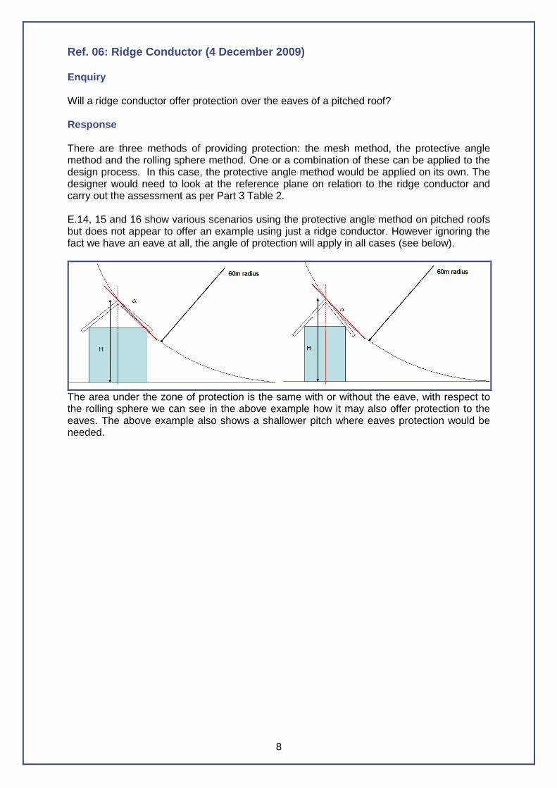
Ref. 06: Ridge Conductor (4 December 2009) Enquiry Will a ridge conductor offer protection over the eaves of a pitched roof? Response There are three methods of providing protection: the mesh method, the protective angle method and the rolling sphere method. One or a combination of these can be applied to the design process. In this case, the protective angle method would be applied on its own. The designer would need to look at the reference plane on relation to the ridge conductor and carry out the assessment as per Part 3 Table 2. E.14, 15 and 16 show various scenarios using the protective angle method on pitched roofs but does not appear to offer an example using just a ridge conductor. However ignoring the fact we have an eave at all, the angle of protection will apply in all cases (see below).
The area under the zone of protection is the same with or without the eave, with respect to the rolling sphere we can see in the above example how it may also offer protection to the eaves. The above example also shows a shallower pitch where eaves protection would be needed.
9
Ref. 07: Thermal Effects (11 December 2009) Enquiry BS EN 62305 states that on a Non Isolated Lightning Conductor System where the thermal effects at the point of strike or on conductors carrying the lightning current may cause the roof finish to combust, the spacing between the LPS and the roofing felt should be at least 0.1m. Is the normal method of laying roof tapes on roof felt safe in terms of combustion? Response It has always been custom and practice in the UK to fix roof tapes to roofing felt using strips of high grade roof felt heat treated to the finished surface thus preventing any fixing penetrations through the waterproof layer and reducing any potential tripping hazards generally in line with guidance from BS 6651 and specifically clause 5.3 in terms of Thermal Effects. Unfortunately there is no guidance given in BS EN 62305 on what temperatures specific roofing materials can withstand prior to combustion; however, we can take guidance from BS EN 62305-1 in terms of the temperature rise of conductors and can see that at 50mm2 the temperature rise on the basis of the conductor carrying all of the lightning current at the point of strike is given as 52oC and this drops to approximately 32oC when using industry standard 25 x 3mm conductors. When considering that the ignition temperature of roofing felt is around 365oC (information courtesy of German loss prevention insurers), there is no perceived risk.
10
Ref. 08: Jointing Compound (15 March 2010) Enquiry Are WD40 and similar products suitable for use as oxide inhibiting applications? Response Whilst WD40 and similar products have a water repellent property and should render the mating surfaces clear of moisture they are not intended to provide long term protection against the ingress of moisture. A proprietary oxide inhibiting paste creates a seal against the ingress of moisture and should stay present on the mating surfaces in all but the most extreme conditions. It is recommended that only proprietary oxide inhibiting pastes are applied prior to final assembly in order to reduce the risk of corrosion to joints and bonds etc.
11
Ref. 09: Metal Under Non-Conducting Roof (13 April 2010) Enquiry Under BS EN 62305-3 clause 5.2.5 item b the use of metal under a non-conductive roof as a part of the air termination network is acceptable. Where could this situation exist and what guidelines should be followed? Response Under this clause, you are informed that metal components under a non-conducting roof may be used as part of the air termination network. This clause must be used with great care as its intention is to give the designer guidance on the use of metallic frames directly under the roof surface, for example on an asbestos or other thin fragile roof where it may not be practicable to install conductors over the roof surface for health and safety reasons. This clause is not intended to allow the use of steel roof trusses that are ‘well’ insulated (e.g. membrane covered roofs). Wherever possible the air termination network should be exposed to a lightning strike and the addition of finials and/or strike plates should be proposed to extend any system to the external face of the structure if the system is concealed.
12
Ref. 10: Testing of Structural Reinforcing (13 April 2010) Enquiry Under BS EN 62305-3 clause 4.3 we are asked to conduct tests to show that continuity exists from the top of the structure to the bottom and that a resistance value of <0.2Ω is achieved. Is there any further advice on this matter? Response The purpose of the test is to show that a low resistance path from the top of the structure to the bottom exists. Testing should be carried out using a suitable meter. The meter should be able to apply at least 10amp in the appropriate range such as the Megger DLRO10HD which can push the full 10amp on a 250mΩ range when used with the KC series test leads which come in 30, 60 & 100m lengths. At least one complete test should be carried out and the values recorded. Ideally the test should be carried out between high and low level. However, if that is not possible, continuity testing at each ‘lift’ in the structure should be performed and the results added together (using the resistances in series theory). The test instrument should be capable of recording hundredths of an Ohm (2 decimal places as a minimum) or preferably a meter that again can push 10amp and be capable of recording very low values (mΩ).
13
Ref. 11: Bonding Structural Steel Columns (13 April 2010) Enquiry Under BS EN 62305-3 clause E.4.3.7, there is a recommendation that where the system is utilising the conductive frame each column should be bonded back to the structure. Is there any further advice on this matter? Response At each of the down conductor positions the columns should be bonded to the earth termination network. The recommendation that every ‘steel’ column should also be bonded back to the structure is covered under the UK guide to BS EN 62305 (BIP 2118). The guide suggests that the LPS Specialist Contractor should ensure by liaising with his contractual principles that the columns are made continuous with the reinforcing at ground level. Additional bonding of the columns would not be required where the method used to fix the steel column to the ground slab/beam/pile is inherent due to the construction process (5.3.2.4).
14
Ref. 12: Type “B” Earth in Service Trench (11 May 2010) Enquiry When installing a Type “B” earthing system:
1. Is it normally the case that the contractor will wish to include the Type “B” earth conductor within the service trench?
2. If yes, are there any requirements in terms of the proximity of power cables and other services for bonding with in the trench?
3. Can Equation 4 in 6.3 be used to determine the separation distance below ground?
Response
1. Yes, provided certain precautions are taken. 2. The proximity to the cable i.e. the separation distance would not be applicable if the
services are equipotentially bonded to the LPS at the service entry. (Note: It would not be right to carry out equipotential bonding of any service without the consent of the service provider.) If the services are not bonded to the LPS, the standard appears only to cover a Type A system where the separation distance would depend on the electrical impulse strength, the resistivity of the soil and the current in the electrode (E.5.4.3.3). With regards to the Type “B”, reference can be found in TS 3.1.2 (National Grid Technical Specification) where the minimum distance from an uncovered metallic sheath is 3m. This we understand is to limit the magnitude of any induced voltages in to the system.
BS EN 62305-3, clause 5.4.3 refers to a depth of at least 0.5 m and ‘about’ 1 m from the structure; however, as a guide some flexibility to meet construction limitations on a site could for example allow a tolerance of 0.5m either way.
3. We do not believe that Equation 4 can be used for this purpose as it does not
address the factors of a buried conductor. In summary, it may be permissible to bury the earthing conductor of a Type “B” system in a service trench as long as the service and other cables are not bare and have been bonded equipotentially to the LPS (either directly or via SPDs). If possible, a conductor should be run beneath any service it encounters and should not be bonded in the trench as this may have an impact on any future testing of the earth system. Where this can be avoided it should be and the earth conductor laid on its own.
15
Ref. 13: Plant – Power Cable on Roof (21 May 2010) Enquiry An item of plant is located on the roof of a building and is of sufficient thickness to withstand a direct lightning strike. It is within the zone of protection afforded by a nearby lighting column and there is sufficient space surrounding the plant to satisfy the calculated separation distance. What, if anything, would need to be applied to the power cable coming from the piece of plant and feeding into the building? Response If the power cable has an effective outer core screen nothing further is required. If it doesn’t have an effective screen and there is a lightning discharge, an induced voltage may appear on the cores of the cable. (Note: In the majority of cases the design engineer would not be able to determine the screen type/make up and in this case we should disregard the screen.) The engineer should then consider bonding the cores of the power cable at rooftop level via Type II overvoltage SPDs. (Note: In this case the lighting column would be susceptible to a direct strike and as such the supply cables feeding the lighting columns should also be assessed for any required SPDs.)
16
Ref. 14: Plant – Insufficient Roof Thickness (21 May 2010) Enquiry An item of plant is located on the roof of a building and is of insufficient thickness to withstand a direct lightning strike. There are several pieces of roof furniture located in very close proximity making the calculated separation distance impossible to achieve. What actions need to be carried out with regard to the protection of the plant and the power cable emanating from the plant and feeding into the building? Response A finial (lightning rod) of relevant height (using protective angle or rolling sphere method to establish this) should be installed by the side of the plant to ensure it does not receive a direct strike in the event of a lightning discharge. The finial should be bonded directly to the casing of the plant and to the air termination network. If there was a lightning discharge to the finial, partial lightning current would flow via the casing into the power cable. A Type 1 lightning current SPDs should be installed at rooftop level to the live cores of the power cable to mitigate this.
17
Ref. 15: Protection of Temporary Structures (29 July 2010) Enquiry Should temporary structures such as spectator stands, construction project scaffolding etc. be provided with a lightning protection system? Response In terms of BS EN 62305:2006 and formerly BS 6651:1999, it is stated that agreement should be reached between all of the principle consulting parties relating to their particular areas of responsibility. A risk assessment should be carried out on any structure, be it temporary or not, where the risk to human life may exist in the event of a lightning strike (for example a spectator stand). In such cases, a system should be installed to the required level of protection if the outcome of the risk assessment is positive. Other areas of concern such as scaffolding, cranes, hoists etc. are covered under BS EN 62305-3 clause E.4.2.2.2.5 where it recommends the use of the permanent earth system as a means of earthing such structures. Of course, if this is not possible, other arrangements would need to be made such as temporary earth electrodes. It is possible in the case of scaffolding to offer further protection by the addition of vertical scaffold poles being erected at critical points on the structure such as the corners.
18
12536
Gas
Water
Meter
Meter
Equipotential
Bonding bar
Central heating
pipe work
Electronic appliances
Screens of antenna cables
Other
Telecoms
Power
Metal elements
Running through
the structure
(e.g. lift rails)
DANGER
Typical Equipotential Bonding
Lightning Protection
System
125361253612536
Gas
Water
Meter
Meter
Equipotential
Bonding bar
Central heating
pipe work
Electronic appliances
Screens of antenna cables
Other
Telecoms
Power
Metal elements
Running through
the structure
(e.g. lift rails)
DANGER
Typical Equipotential Bonding
Lightning Protection
System
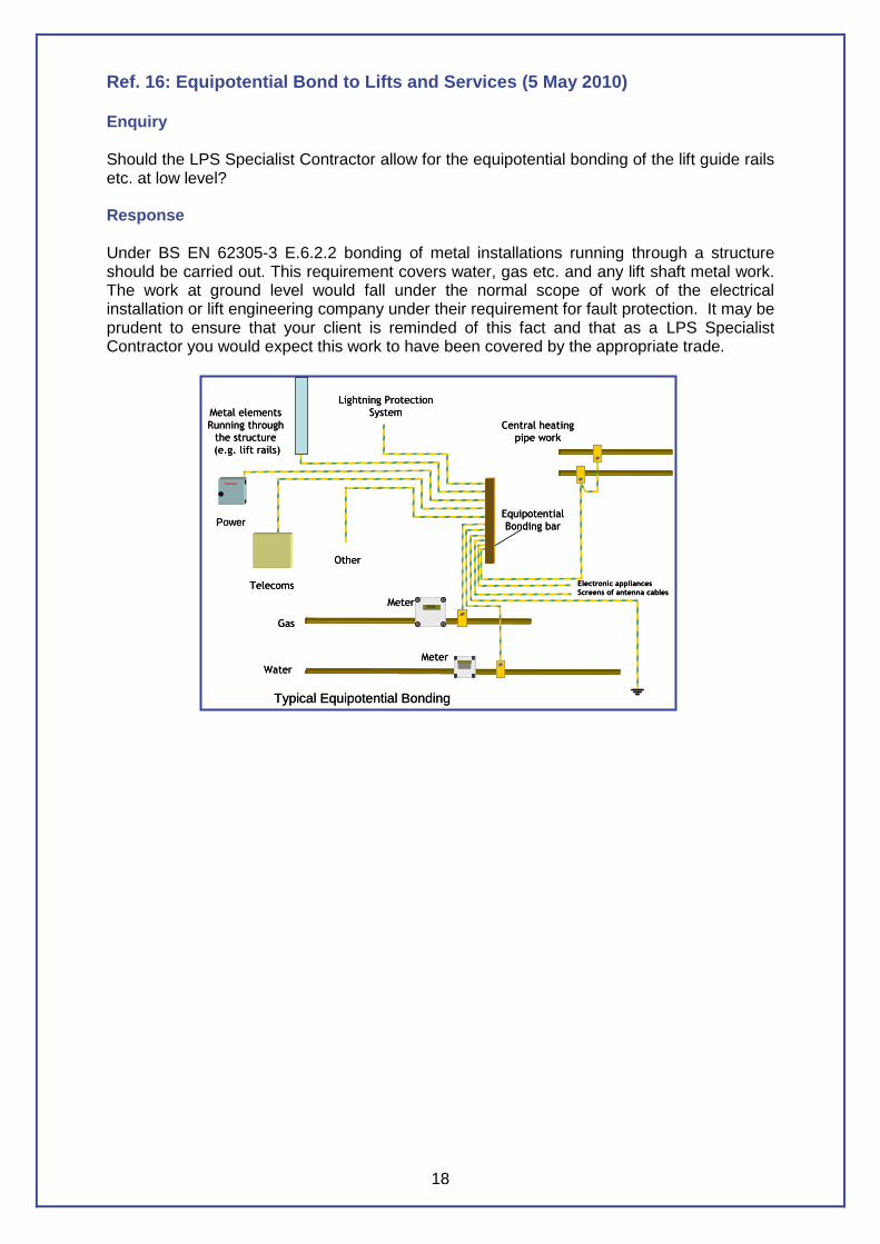
Ref. 16: Equipotential Bond to Lifts and Services (5 May 2010) Enquiry Should the LPS Specialist Contractor allow for the equipotential bonding of the lift guide rails etc. at low level? Response Under BS EN 62305-3 E.6.2.2 bonding of metal installations running through a structure should be carried out. This requirement covers water, gas etc. and any lift shaft metal work. The work at ground level would fall under the normal scope of work of the electrical installation or lift engineering company under their requirement for fault protection. It may be prudent to ensure that your client is reminded of this fact and that as a LPS Specialist Contractor you would expect this work to have been covered by the appropriate trade.

19
Ref. 17: ESE and UK Standards (28 March 2011) Enquiry We are advised that the use of Early Streamer devices (ESEs) are particular to French Standard NF-C-17-102 and as such comply with new European Standards but no such standard for ESE devices exists in the UK. Can you please clarify this and explain the technical differences? Response It is correct that there is no standard within the UK representing the support of ESE devices given that each member country of the European Standards bodies is obliged to adopt the European Commission’s Essential Requirement on Technical Harmonisation: “Standards remain voluntary but their transposition into National Standards and the withdrawal of diverging national standards is mandatory according to the internal rules of the European Standards Organisations [sic].” Each member country is therefore obliged to adopt the EN standard as a national standard, with the national standard prefix preceding EN, i.e. BS EN, and as such in the UK BS 6651 was withdrawn and replaced with BS EN 62305:2011. With regards to technical differences, the argument appears to centre on the alleged speed of the upward leader emanating from the ESE devices as opposed to the Franklin Air Rod and is the subject of continued debate. It may be better to refer to the considerable quantity of information available in the public domain by visiting the many websites available. Whether you choose to install an ESE device or not, the physics in terms of the conduction and dissipation of the captured lightning current remain the same. In this respect, the detailed design philosophy shown in BS EN 62305-2 should be applied in order to achieve a safe design level. When this is obtained, it is simply a case of ensuring that the structural protection is applied strictly in line with BS EN 62305-3 (see Annex A) and that the electrical/electronic equipment in and on the structure is protected in line with BS EN 62305-4. It should be noted that no part of the suite of BS EN documentation should be applied in isolation. (Note: Building owners and designers are subject to the Health and Safety at Work Act, Electricity at Work Regulations (Reg. 6) and Management of Health and Safety Regulations (Reg. 3) and as such Risk Assessments should be undertaken and this requirement should be satisfied by the implementation of BS EN 62305-2.)
20
Ref. 18: Use of Tek Screws for Bonding (12 March 2012) Enquiry Can self-drilling TEK screws be used to bond to roof plant/metallic cladding? Does this method of bonding comply with BS EN 62305? Response A proprietary component designed for clamping the conductor to the roof plant/cladding such as a “B” bond should be used whenever possible. This component should conform to BS EN 50164-1:2008 Lightning Protection Components. However, in circumstances where there is no access to the back of the roof plant/cladding, a “B” bond would not be suitable. BS EN 62305 does not give detailed specific advice on this subject. Clause 5.5.3 refers to connections which it can be assumed also relates to bonding terminations, with some general guidelines. What can be stated is that all bonding conductors and their terminations should be capable of carrying lightning currents without causing damage, hot spots or burning at the termination interface. Minimum sizes of bonding conductors are given in Table 8. The fixings/terminations should be able to withstand the mechanical forces developed during a lightning discharge and be compatible with the material that it is bonding to so as to minimise any potential corrosion problems. The termination should be installed in such a manner that it is in intimate contact with the face of the conductor, with a minimum of 3 fixings per termination. The use of a “B” bond should always be the preferred option. The use of self-tapping screws should only be used when there is no other option and must always be open for inspection.
21
Ref. 19: Continuity of RI-Steelwork when Used as Down Conductors (23 April 2012) Enquiry When using the structural reinforced steel or metal framework to form the down conductor paths, is it necessary to obtain a continuity reading of 0.2 ohms in all locations? Response BS EN 62305-3 states that for structures utilising steel reinforced concrete the electrical continuity of the reinforcing bars shall be determined by electrical testing between the uppermost part and ground level and that the overall resistance should not be greater than 0.2 ohms. The use of the term ‘overall resistance’ would indicate that as long as an overall resistance of less than 0.2 ohms is achieved between the uppermost part and ground level, the reinforcing is suitable for use as part of the LPS and a measurement at each location is NOT required. It is further stated that steelwork within reinforced concrete structures is considered to be electrically continuous provided the connections of the vertical bars are welded, clamped or overlapped a minimum of 20 times their diameter and bound or otherwise securely connected. It is therefore vital the above connection methods are adhered to and that connections are made to two reinforcing bars as shown in figure 5.1 of the BIP Guide.
22
Ref. 20: Reference Earth Electrodes (16 May 2012) Enquiry How and when should Reference Earth Electrodes be installed? Response Reference Earth Electrodes are required where a foundation earth is utilised for the Earth Termination System and for maintenance testing. It is important to perform the testing of the foundation earth at the correct stage of construction and to record the results of the individual pile or pad foundation resistances while these are still in isolation so it can be ensured that the maximum resistance of 10 Ohms is not exceeded. BS EN 62305-3:2011 clause E.4.3.9 states that where it is not possible to measure the earthing resistance of the foundation earth, one or more reference earth electrodes close to the structure will provide a possible method of monitoring the changes in the environment over the years by performing a circuit test between the electrode and the foundation earth. To facilitate this test, there will have to be a connection from the structure to the electrode(s). This may be in the form of a permanent copper conductor connection, or via an exposed earthing point on the structure with testing wire to the electrode at the time of the test. The electrodes themselves should be installed to a depth to provide a stable earth resistance, i.e. a minimum of 2.4m, and consideration should be given for greater depths where the soil resistivity is high. No specific guidance is given on the quantity of these electrodes; however, good practice would be to have a minimum of two located at opposite extremes of the site, with consideration for more electrodes for large structures placed one for each 100m of perimeter as recommended by BIP 2118.
23
Ref. 21: Use of Metal Guttering in Air Termination Systems (17 May 2012) Enquiry Could you advise on the use of metallic guttering that may form part of the air termination system? Response The use of metallic guttering as part of the LPS has over many years been seen as an option for the design engineer. Its use can result in some cost savings but in many cases its attraction has been for aesthetic reasons. Its use is documented in many areas of BS EN 62305:2006. For example, clause E.5.2.4.2 clearly states that gutters may be used as part of the lightning conductor system. However, it does go on to state that it must also comply with section 5.2.5 of Part 3. Under section 5.2.5 (a ‘normative’ section of the standard), we are told that a ‘natural’ component of the LPS must provide no less than that specified for a standard air-termination component. With this in mind, the following should apply to the guttering under consideration:
1. It must be of adequate thickness in order to sustain the forces and stresses of a lightning strike, referring to Table 3 in BS EN 62305-3 will give you the information.
2. It must have electrical continuity throughout the sections under consideration.
Particular attention must be focused on joints; experience shows that joints in gutter systems may show electrical continuity at the time of installation but over time the ingress of dirt etc. has resulted in systems failing annual testing (the result of which is a costly exercise of installing eaves conductors). Any joints used must comply with the BS EN 50164 series of lightning protection component standards which require lightning conductor components to undergo rigorous testing to ensure they last the life of the system.
In summary:
a. A gutter may be used as a part of the LPS b. In order to use the gutter, it must comply with the minimum material thickness c. All joint components must comply with the BS EN 50164 series of lightning protection
component standards.
24
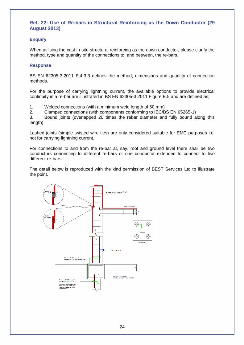
Ref. 22: Use of Re-bars in Structural Reinforcing as the Down Conductor (29 August 2013) Enquiry When utilising the cast in-situ structural reinforcing as the down conductor, please clarify the method, type and quantity of the connections to, and between, the re-bars. Response BS EN 62305-3:2011 E.4.3.3 defines the method, dimensions and quantity of connection methods. For the purpose of carrying lightning current, the available options to provide electrical continuity in a re-bar are illustrated in BS EN 62305-3:2011 Figure E.5 and are defined as; 1. Welded connections (with a minimum weld length of 50 mm) 2. Clamped connections (with components conforming to IEC/BS EN 65265-1) 3. Bound joints (overlapped 20 times the rebar diameter and fully bound along this length) Lashed joints (simple twisted wire ties) are only considered suitable for EMC purposes i.e. not for carrying lightning current. For connections to and from the re-bar at, say, roof and ground level there shall be two conductors connecting to different re-bars or one conductor extended to connect to two different re-bars. The detail below is reproduced with the kind permission of BEST Services Ltd to illustrate the point.
25
Ref. 23: Cross Bonding Internal Columns with the Earth Termination System
(13 September 2013)
Enquiry
When cross bonding the internal columns of a building to the air termination system and the
earth termination system, should the conductor be considered as current carrying or be
treated as an equipotential bonding conductor?
Response
BS EN 62305-3:2011 E.5.3.4.2 clearly states that to avoid dangerous sparking between
different conductive parts internal columns should be bonded to the air termination system
and the earth termination system and as a result a portion of the lightning current would flow
through these internal down conductors. This would indicate that these connections and
conductors should be considered as current carrying and not as equipotential bonding
conductors.
BS EN 62305-3:2011 E.5.4.3.6 also states that internal down conductors or internal
structural parts used as down conductors should be connected to an earth electrode and the
reinforcement steel to avoid step and touch voltages which when read with E.5.3.4.2 would
indicate that all columns which are bonded would be subject to carrying current and as such
should be treated as current carrying conductors.
The correct cable size for this purpose would be 50mm².
26
Ref. 24: Retrospective installation of lightning conductor fixings to existing
tiled / slate roofs using standard slateholdfasts (18 February 2014)
Enquiry
Can the Technical Committee comment on the retrospective installation of lightning
conductor fixings to existing tiled / slate roofs using standard slateholdfasts inserted between
overlapping tiles and secured using a suitable exterior ‘grab’ adhesive? As this installation
procedure has been common practice for installers for well over 30 years, can this be
considered as an industry standard practice and compliant with the current requirements of
BSEN62305?
Response
BSEN62305 does not offer specific guidance for this method of fixing, only that it shall be
firm and shall maintain the watertightness.
The relevant text that can be found in Part 3 is as follows;
5.5.2 Fixing
Air-terminations and down-conductors shall be firmly fixed so that the electrodynamic or
accidental mechanical forces (for instance vibrations, slipping of slabs of snow, thermal
expansion, etc.) will not cause conductors to break or loosen (see Annex D of 62305-
1:2010).
E.4.2.2.2.5 Builder and installer
Agreement on the following items should be reached between the builder, installer, and
those responsible for construction of the structure and its technical equipment:
k) the construction to be employed for roofs and walls in order to determine appropriate
methods of fixing LPS conductors, specifically with a view to maintaining the watertightness
of the structure;
The method of fixing described can be considered very common practice within the UK. This
applies to the installation of lightning conductors to surfaces of existing tiled/slate roofs
where penetrative fixings are not practicable, and has historically been used to great effect;
providing a secure and effective fixing.
This method is reliant on the pressure/friction exerted by the overlying tile/slates with the
addition of an exterior grade adhesive to assist in security. Once the conductor has been
secured to the fixings clips, this creates the effect of ‘locking’ the fixings and conductor
together preventing any slippage.
Where there is a requirement for the fixing of horizontal conductors on tiled roofs, e.g. along
at ridge level or more importantly at eaves level, it may require a reduction in the fixing
centre length thus reducing the ‘sag’ effect. The potential external influences of the weight of
snow/windage etc. should be examined and if failure of the fixings is considered likely, an
alternative method of fixing (e.g penetrative or built-in fixing) should be considered.
27
Ref. 25: Using BS 6651 as a Reference Standard (8 April 2014)
Enquiry
Can the Technical Committee please advise on whether it is acceptable to use BS6651 as
the reference Standard for new installations and/or maintenance work including inspection
and test.
Response
BS6651 was withdrawn in September 2008 and all installations requiring a British Standard
system after this date should be designed to BS EN 62305 and certified accordingly.
Where an existing Lightning Protection System, installed to an earlier standard than BS EN
62305, undergoes an inspection and test and repairs are found to be required, the Standard
of the original design shall be used to evaluate the works required. For example, with a BS
6651 installation, the inspecting company may use the ‘10x’ resistance rule for evaluating
individual earth resistances.
If it is not possible to identify the original design Standard, a discussion with the client of the
options should be undertaken.
It is in order for advice to be given to the client that the Standards have changed but, as
there is no legislative requirement to upgrade, they should not be pressured to do so.
However it may be prudent to point out to the client that a superior protection system would
be gained by the conversion to BS EN 62305 which reflects the current lightning protection
knowledge.
28
Ref. 26: Bonding of Solar Panels (25 April 2014)
Enquiry
Should solar panels be bonded? If a separation distance cannot be achieved, should they
be bonded to the lightning protection system?
Response
Protection of solar panels, particularly the photovoltaic type (PV), is best achieved by the
fitting of vertical finials and the creation of a protected zone (rolling sphere or protective
angle).
If separation distances cannot be maintained, then the bonding of the panel framework shall
also be undertaken.
Suitable surge protection devices should be recommended for the PV equipment - Type 1
for where separation distances cannot be maintained and bonding is needed, and Type 2 for
where the separation distance can be maintained and, in both cases, the SPD should be to
the Lightning Protection Level 1, 2, 3 or 4 as determined by the Risk Assessment.
Specialised devices for solar equipment are required but are readily available.
29
Ref. 27: Lightning Protection for Scaffolding (24 June 2015)
Enquiry
The client has recently constructed a scaffold footbridge across the dual carriageway
between two halves of the current construction project and is concerned about employees
on the bridge during thunderstorms. What parameters should be applied to protect persons
crossing the bridge from the effects of lightning whilst still maintaining safe site conditions?
Response
Where temporary structures such as scaffolds are assembled using bolted joints or screw
clamps the multiplicity of such connections is likely to provide several paths of relatively low
resistance. Although such structures are not designed to be electrically continuous, it is
reasonable to assume that they have an inherently low value of electrical resistance. For
lightning protection purposes, in all cases the materials used for the construction of the
temporary structure must meet with the requirements of clause 5.2.5 and table 3 related to
the air termination (scaffold roofing) and clause 5.3.5 and table 6 related to the natural down
conductors. Whatever type of structural fastenings or footings in contact with the ground are
employed, and however a temporary structure is fastened to a permanent structure, it should
not be assumed that a temporary metallic structure is effectively earthed.
If scaffolding is associated with an existing structure which has an external lightning
protection system (LPS), it should be bonded to the earth termination network and the air
termination network of the LPS. Where no LPS exists on the structure the scaffolding should
be provided with an LPS at a design level where indicated by a risk assessment performed
in accordance with BS EN 62305-2.
Where persons are required to work on, close to, or traverse a fixed scaffold it is good
practice to extend the scaffold (pole) above the height of persons on the scaffold relative to
the design level thus providing a form of air terminal zone of protection. In general where
persons congregate on scaffolding or on roofs, warning signs should be provided at the
entrances drawing attention to the danger of potential lightning strikes during thunderstorms.
Except where it is necessary for lightning protection systems to comply with BSEN 62305,
scaffolding external to a structure should not be connected to the means of earthing within
the structure that is afforded by supply authorities. Equipotential bonding where deemed
necessary will be undertaken by the electrical contractor in all circumstances. Where doubt
still exists, the client can be directed to their Local Authority and HSE guidance on Scaffold
Protocol and their reference to the National Access and Scaffolding Confederation (NASC)
guidance document SG3 and where appropriate to the Highways Act.
30
Ref. 28: Earth Rod Resistance Values (6 August 2015)
Enquiry
We have been asked by our client if the rules in BS 6651 Clause 17.1 regarding earth
electrode resistance values have changed in terms of the maximum value of resistance
allowed for each individual earth rod not to exceed the product given by 10 times the number
of earth electrodes in the system. For example, if the building has 10No down conductors
each earth electrode would only be allowed a maximum of 100 Ohms. This question has
been raised by our client on the basis that they have been advised that as long as the overall
system achieves less than the maximum 10.0 Ohms overall there is no requirement in BS
EN 62305 to maintain the individual electrodes at or less than the 10 times rule.
Response
It does appear to be the case that BS EN 62305-1 to 4 doesn’t specifically make reference to the individual earth rod resistance values in the same way as BS6651 clause 17.1. What does remain however is the safety aspects of ensuring that each of the individual earth electrodes is of a sufficiently low value to disperse the lightning current into the earth without causing thermal or mechanical damage, dangerous sparking/ flashover which may trigger fire or explosion and just as important if not more so to reduce the risk of dangerous potential gradients around the earth termination.
By ensuring that each resistance value is kept as low as possible these risks can be reduced to tolerable levels as stated in 62305. Given that 62305 states that earth termination systems should perform the following three tasks i.e. Conduction of the lightning current into the earth – Provide equipotential bonding between the down conductors – Potential gradient controls, BS EN 62305 is keen to promote the Type B ring earth electrode principle as this addresses all three of these requirements inherently and takes account of the lightning current distribution which is generally much higher at the corners of a building than elsewhere around the building whereas the Type A individual vertical rods do not.
Although not stated in the same way as BS 6651 clause 17.1 the intent within 62305 is still the same in that a low resistance value at each Type A earth termination position will address the risks stated above but in general the lower the overall resistance value is the safer people and the structure will be. As can be seen in 62305 the overall 10.0 Ohm rule cannot be taken in isolation as a simplified target value as there are many complex design issues to address in terms of the overall safe performance of the lightning protection system.
In summary, where doubt or argument still exists you can refer the client to the BSI Guide to BS EN 62305 (BIP 2118) section 5.3.4 which has been reviewed by and has the endorsement of GEL/81 British Standards Institute Lightning Protection Committee and the Association of Technical Lightning & Access Specialists (ATLAS) Lightning Protection Committee.
31
Ref. 29: Down Conductors – Cavity Walls (25 August 2016)
Enquiry
Is it possible to install 25 x 3mm PVC sheathed aluminium tapes within a cavity wall of a brick clad, timber framed building to act as the down conductors on a level 4 system?
Response
BS EN 62305-3:2011(clause 5.3.4) states that:
if the wall is made of non-combustible material the down conductors may be positioned on the surface or in the wall.
if the wall is made of readily combustible material the down conductors may be positioned on the surface of the wall, provided that their temperature rise due to the passage of lightning current is not dangerous for the material of the wall.
Additionally, in BS EN 6305-1:2011 table D3, the temperature rise given for 50sqmm aluminium (and we are using 75sqmm) for a maximum specific energy of 10 MJ/ohm is 52 deg C. The PVC coating is capable of withstanding 200 deg C for 75 minutes.
Information from the Timber Research & Development Association has informed us the ignition point of timber is 300 deg C.
Based on the above we believe that the cavity wall brick clad timber frame building does not constitute a readily combustible material, where the temperature rise will be dangerous to the material of the wall (timber) and as such the installation of 25 x 3mm PVC aluminium tape may be positioned on the timber frame wall within the cavity. Internal bonding and surge protection measures should be re-evaluated as appropriate to take into consideration the proximity of the conductors to cabling and metallic services within the structure in line with separation distances as described within Clause 6.3
So that future testing can be properly undertaken, test points must be external.
ATLAS
6-8 Bonhill Street, London, EC2A 4BX
T: 0844 249 0026 F: 0844 249 0027 E: [email protected]
Company No. 5026089 Registered in England VAT Registration No: 245 6019 69