Embed Size (px)
Citation preview
Lighting Tool Box Lighting Tool Box
Machine Vision LightingMachine Vision Lighting Team Members:Team Members: B. ThompsonB. Thompson
N. SitarskiN. Sitarski
B. HarrisB. Harris
D. ChronicleD. Chronicle
V. GergovV. Gergov
Advisor: Advisor: J. W. MillerJ. W. Miller
University of Michigan-DearbornUniversity of Michigan-Dearborn
Introduction to Lighting Tool BoxIntroduction to Lighting Tool Box
Lighting Tool Box system function and Lighting Tool Box system function and purposepurpose
Lighting Tool Box componentsLighting Tool Box components– LED Light ControllerLED Light Controller– Incandescent Light ControllerIncandescent Light Controller– Florescent Lamp ControllerFlorescent Lamp Controller– ComputerComputer
Design ObjectivesDesign Objectives
The goal is to design and implement three lighting The goal is to design and implement three lighting systems that can be remotely controlled via the systems that can be remotely controlled via the internet or locally in a stand alone configuration.internet or locally in a stand alone configuration.
Implementation ChoicesImplementation Choices
Linux/GNU Operating SystemLinux/GNU Operating System– StabilityStability– CostCost– ScalabilityScalability– Open SourceOpen Source
PC104 Embedded SystemPC104 Embedded System– SizeSize– Heat-loadHeat-load– No moving partsNo moving parts
Implementation Choices cont.
Custom hardware for lighting controllers– Off the shelf products are non-existent– Flexibility to make changes– Cost
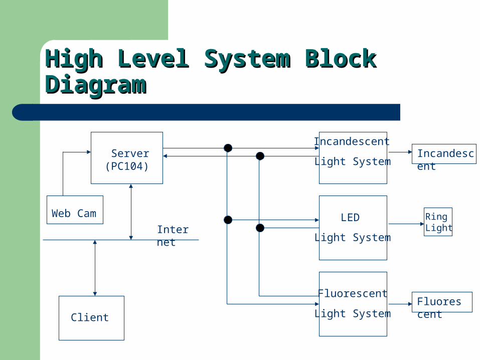
High Level System Block DiagramHigh Level System Block Diagram
Server(PC104)
Incandescent
LED
Fluorescent
Light System
Light System
Light SystemClient
Internet
Web Cam
Incandescent
RingLight
Fluorescent
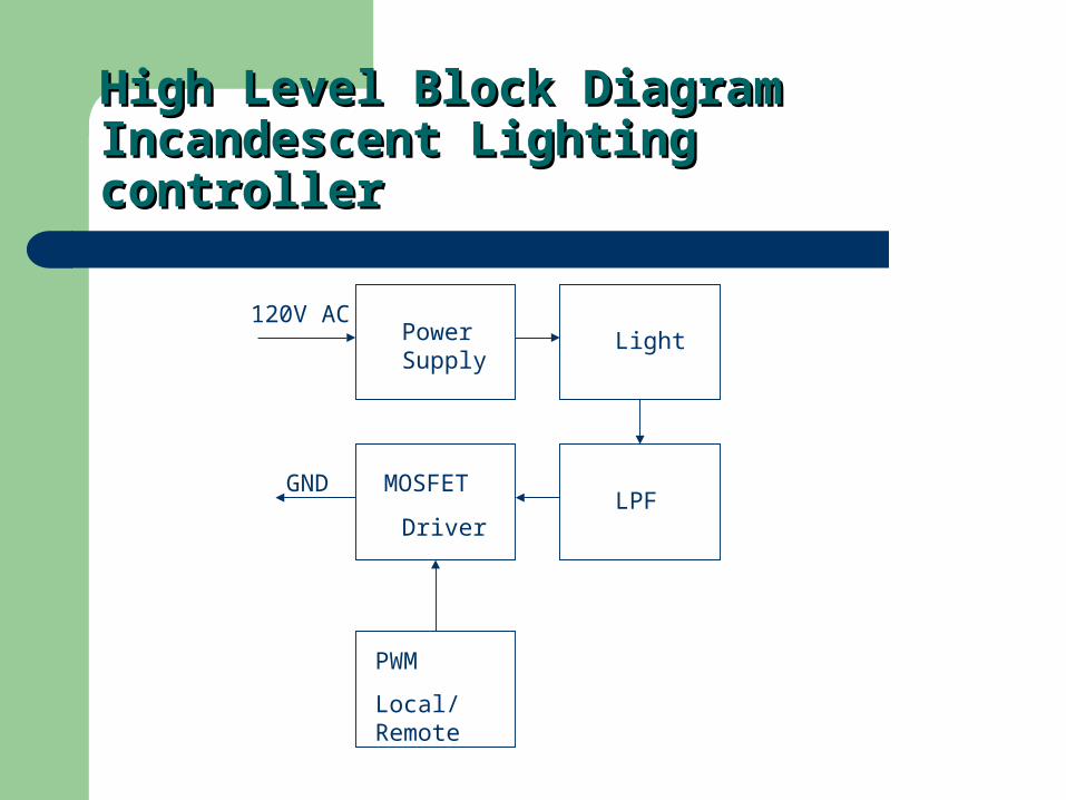
High Level Block Diagram Incandescent High Level Block Diagram Incandescent Lighting controllerLighting controller
Power Supply
120V ACLight
MOSFET
PWM
Local/Remote
LPFGND
Driver

Low Level Block Diagram Low Level Block Diagram Power SupplyPower Supply
Vin 120 V RMS Vout 12 Volts to 18 Volts
Unregulated Rectifier Circuit has a PIV of
36 Volts Diodes Rated at 50 Volts
Maximum Current of Circuit is 20 Amps
Capacitor was Calculated with I=C*(dv/dt) , C = (20 (amps) * 8 (ms)) / 6 (V) = 27,000 uF
68,000 uF Electrolytic was the value closest to the calculated value
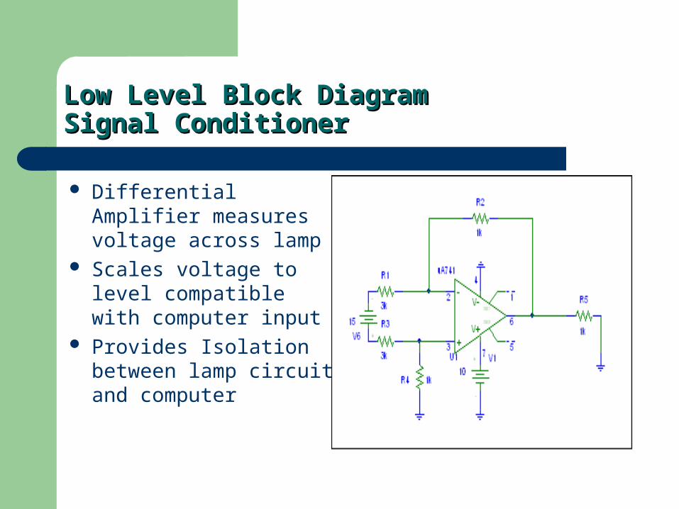
Low Level Block Diagram Low Level Block Diagram Signal ConditionerSignal Conditioner
Differential Amplifier measures voltage across lamp
Scales voltage to level compatible with computer input
Provides Isolation between lamp circuit and computer
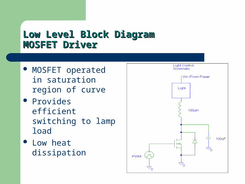
Low Level Block Diagram Low Level Block Diagram MOSFET DriverMOSFET Driver
MOSFET operated in saturation region of curve
Provides efficient switching to lamp load
Low heat dissipation
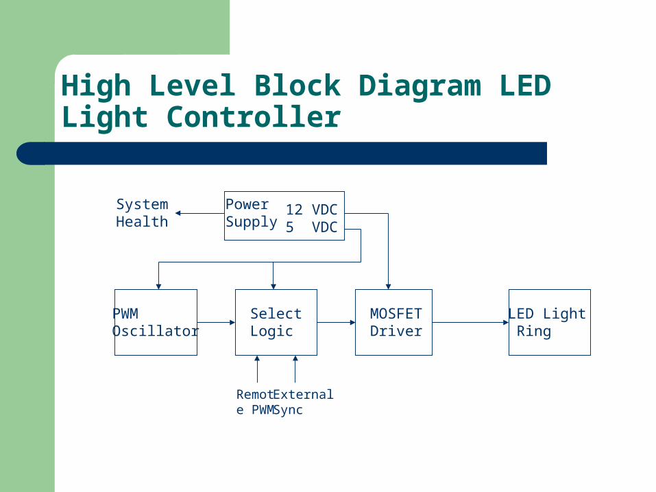
High Level Block Diagram LED Light Controller
LED Light Ring
PWMOscillator
MOSFETDriver
PowerSupply
12 VDC5 VDC
SelectLogic
Remote PWM
ExternalSync
System Health
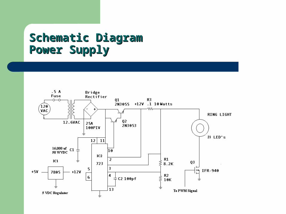
Schematic Diagram Schematic Diagram Power SupplyPower Supply
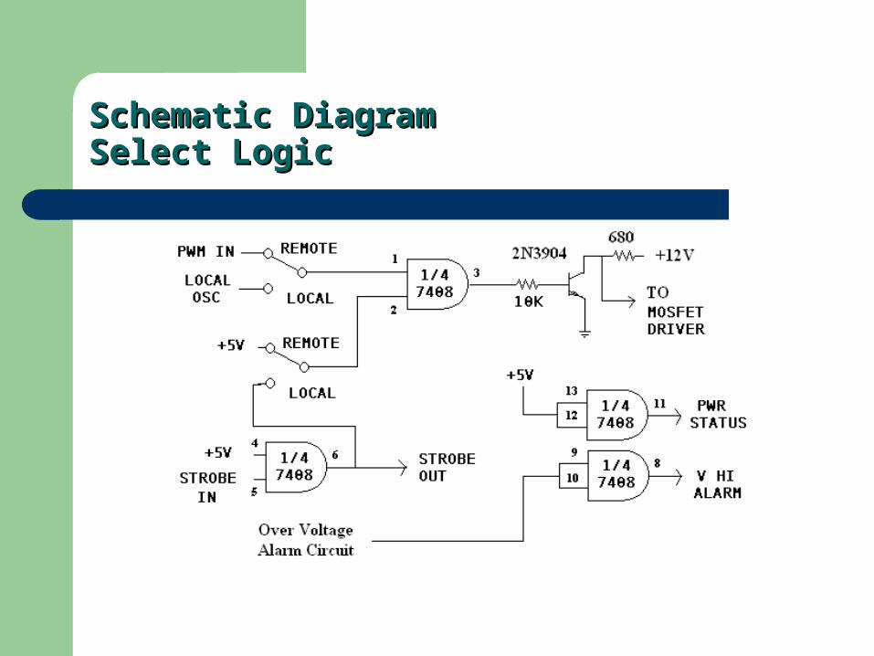
Schematic Diagram Schematic Diagram Select LogicSelect Logic
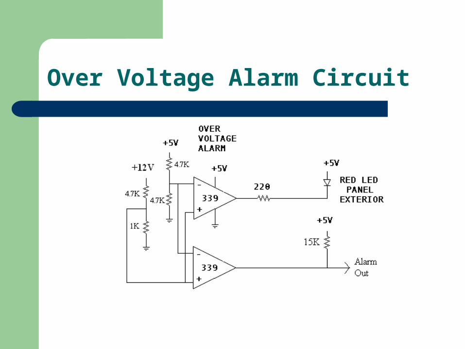
Over Voltage Alarm Circuit
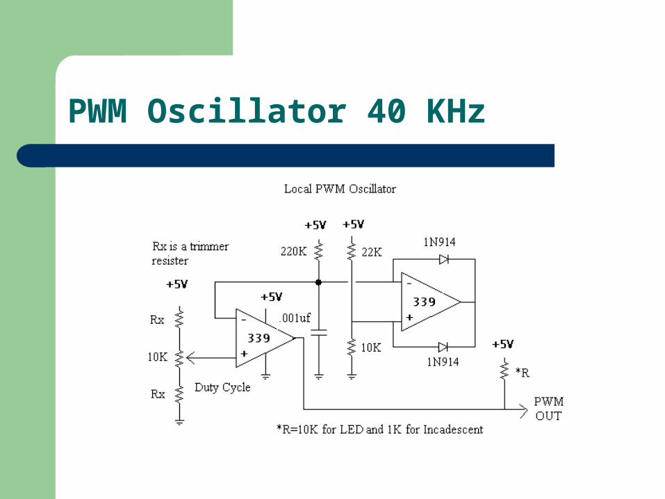
PWM Oscillator 40 KHz
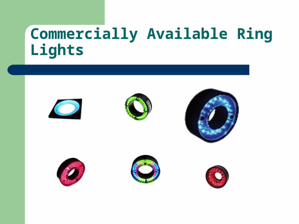
Commercially Available Ring Lights
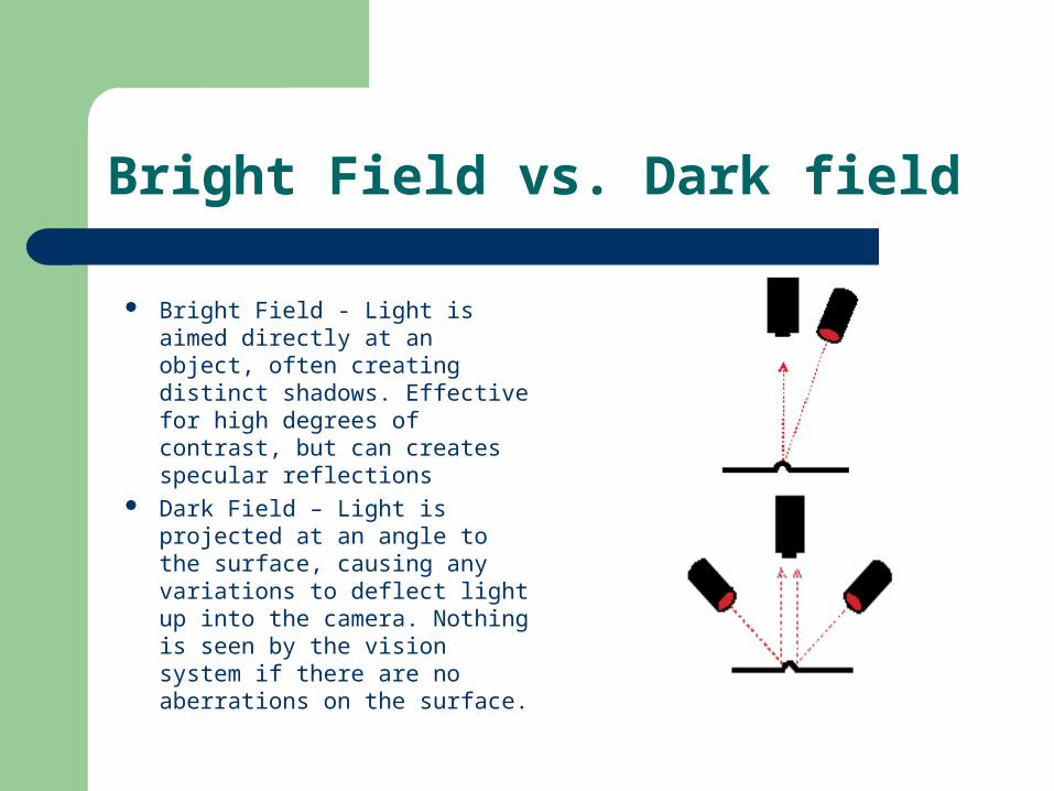
Bright Field vs. Dark field
Bright Field - Light is aimed directly at an object, often creating distinct shadows. Effective for high degrees of contrast, but can creates specular reflections
Dark Field – Light is projected at an angle to the surface, causing any variations to deflect light up into the camera. Nothing is seen by the vision system if there are no aberrations on the surface.
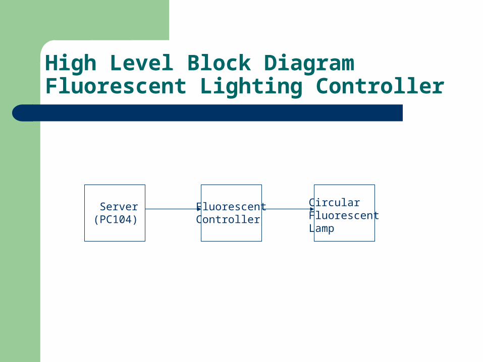
High Level Block Diagram Fluorescent Lighting Controller
CircularFluorescentLamp
FluorescentController
Server(PC104)
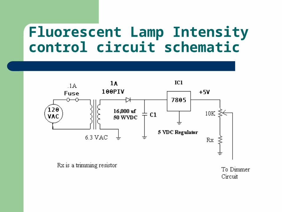
Fluorescent Lamp Intensity control circuit schematic
Project ChangesProject Changes
Lighting controllers will have the capability of Lighting controllers will have the capability of being controlled in stand alone configuration.being controlled in stand alone configuration.
Dave And Vladi’s Completed Tasks
Acquired all needed parts (PC104, I/O Board, 2.5” HDD, Flash, Web Cam, Enclosures, Misc.)
Assembled PC104 and Modules Installed/Streamlined Debian GNU/Linux OS on PC104 (under
100 MB compared with ~1.2 GB min Windows install ) Custom Linux Kernel 2.4.23 configured and compiled with i586
optimization, preemptive task scheduler, and low latency patches
Web Cam Installed and configured with our kernel Web Site code completed in PHP, XHTML 1.0 Strict, and CSS
2.0 in accordance with W3C standards Web Site daemon control module Coded Web Cam Snapshot BASH Script Coded
Dave and Vladi’s Remaining Tasks
Digital I/O Card integration into our kernel Digital I/O daemon control code Testing of code with actual lighting systems Achieve system boot time of ~ 3 sec Miscellaneous enhancements of code and
Operating System
Nick’s Completed Tasks
Power Supply design, test, and construction MOSFET Driver Circuit design, test, and construction Lamp Filter design, test and construction Lamp Head design and construction Heat sinks have been sized and installed on high
temperature components All components have been installed and tested in a
commercially available electronics cabinet, unit is fully functional in local mode of operation
Nick’s Remaining Tasks
Implement computer interface circuit Integrated test of finished product
Blaine’s Completed Tasks
Regulated Power Supply design, test, and construction MOSFET Driver Circuit design, test, and construction Strobe circuit design, test and construction Remote/ Local select logic design, test, and construction LED Ring Light Head design and construction Heat sinks have been sized and installed on high temperature
components Computer interface circuit All components have been installed and tested in a
commercially available electronics cabinet, unit is fully functional in local mode of operation
Blaine’s Remaining Tasks
Integrated system test Possible additional Ring Light configurations
Brandon’s Completed Tasks
Dimmable (from 1 to 100%) 32 watt fluorescent lamp dimmer circuit assembled on board
0-5VDC intensity control circuit System test with 32 watt lamp
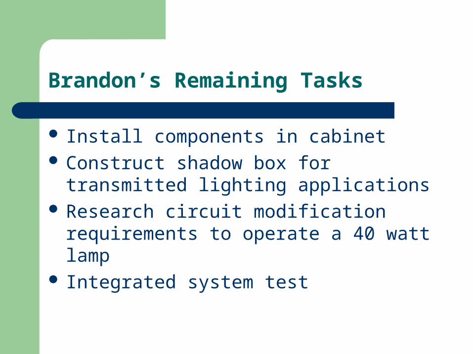
Brandon’s Remaining Tasks
Install components in cabinet Construct shadow box for transmitted lighting
applications Research circuit modification requirements to
operate a 40 watt lamp Integrated system test
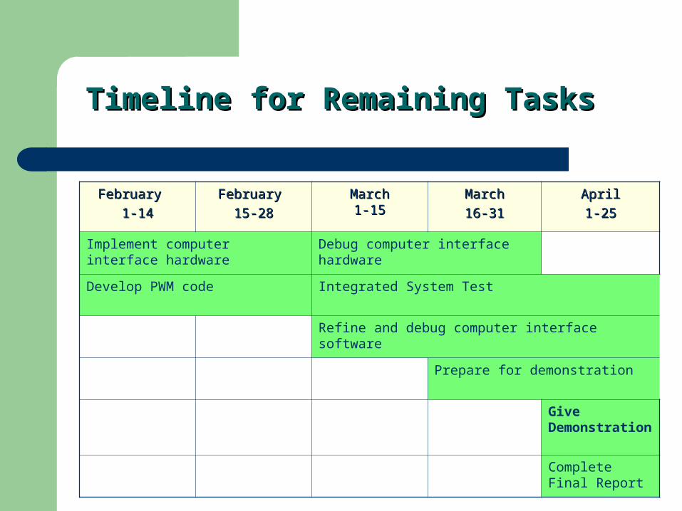
Timeline for Remaining TasksTimeline for Remaining Tasks
February February
1-141-14
February February
15-2815-28
MarchMarch1-151-15
MarchMarch
16-3116-31
AprilApril
1-251-25
Implement computer interface hardware
Debug computer interface hardware
Develop PWM code Integrated System Test
Refine and debug computer interface software
Prepare for demonstration
Give Demonstration
Complete Final Report

FeedbackFeedback
Any questions, comments, or suggestions?Any questions, comments, or suggestions?