Embed Size (px)
Citation preview

UNIVERSITY OF CAMBRIDGE
FACULTY OF MUSIC WEST ROAD CONCERT HALL
GUIDE TO CONCERT HALL LIGHTING


West Road Concert Hall Lighting Guide
Page 3
Contents 1 OVERVIEW...................................................................................................................................5
1.1 INTENDED AUDIENCE...................................................................................................................5 1.2 STANDARD EQUIPMENT PROVISION.............................................................................................5
2 STAGE LAYOUT..........................................................................................................................5
3 LIGHTING SYSTEM ...................................................................................................................7
3.1 HOUSE LIGHTS.............................................................................................................................7 3.1.1 House Light Circuits..........................................................................................................7 3.1.2 House Light Control ..........................................................................................................7
3.2 WORKING LIGHTS........................................................................................................................9 3.2.1 Rear Entrance Working Lights ..........................................................................................9 3.2.2 Stage Working (Rehearsal) Lights ....................................................................................9 3.2.3 “Loft” Gallery Working Lights .......................................................................................10
3.3 PERFORMANCE LIGHTING ..........................................................................................................10
4 PERFORMANCE LIGHTING ..................................................................................................10
4.1 CONFIGURATION........................................................................................................................10 4.1.1 Lighting Plan ...................................................................................................................11 4.1.2 Focus Description ............................................................................................................12 4.1.3 Additional Resources.......................................................................................................12
5 BASIC USE OF THE CONSOLE..............................................................................................13
5.1 CONTROL LAYOUT.....................................................................................................................13 5.2 POWERING ON AND OFF ............................................................................................................14
5.2.1 Starting Up.......................................................................................................................14 5.2.2 Shutting Down.................................................................................................................16
5.3 STANDARD STATE SUBMASTERS ...............................................................................................17 5.5 CONTROLLING INDIVIDUAL CHANNELS .....................................................................................19
5.5.1 Turning Everything Off ...................................................................................................19
6 SETTING UP FOR A CONCERT .............................................................................................20
6.1 HOUSE LIGHTS...........................................................................................................................20 6.1.1 Starting from Darkness....................................................................................................20 6.1.2 If there are already Lights On..........................................................................................20
6.2 WORKING LIGHTS......................................................................................................................20 6.3 PERFORMANCE LIGHTING ..........................................................................................................21
6.3.1 Taking Control of the House Lights from the Console ...................................................22
7 OPERATING LIGHTING FOR A CONCERT .......................................................................22
7.1 BASICS .......................................................................................................................................22 7.1.1 At the Start of the Performance .......................................................................................22 7.1.2 At the Interval..................................................................................................................23 7.1.3 At the End of the Performance ........................................................................................23
7.2 OPTIONAL EXTRAS ....................................................................................................................23 7.2.1 Dimming the Stage Lighting when No-one is on Stage ..................................................23 7.2.2 Adding Front Light for Curtain Calls. .............................................................................23 7.2.3 Entrance / Exit Light .......................................................................................................24 7.2.4 Putting It All Together.....................................................................................................24
8 TROUBLESHOOTING ..............................................................................................................25
8.1 RESTORING THE STANDARD SUBMASTERS ................................................................................25 8.1.1 Selecting the Correct Submaster Page.............................................................................25 8.1.2 Restoring Submasters from Disc .....................................................................................25
8.2 RESTORING THE ENTIRE CONSOLE CONFIGURATION.................................................................28 8.3 RESTORING FROM THE FLOPPY DISC BACKUP ...........................................................................29

West Road Concert Hall Lighting Guide
Page 4
8.3.1 Copying the Configuration to the Local Disk .................................................................30
9 PROGRAMMING AND STORING SUBMASTERS..............................................................31
9.1 HOW TO PROGRAMME A SUBMASTER ........................................................................................31 9.2 HOW TO SAVE SUBMASTER SETTINGS TO DISC .........................................................................32

West Road Concert Hall Lighting Guide
Page 5
1 Overview This guide provides an introduction to, and overview of, the lighting control system installed in the concert hall. The three systems of house lights, working (rehearsal) lights and stage lighting are covered from the operator’s perspective.
1.1 Intended Audience Because a large proportion of the concert hall’s users has no prior knowledge of entertainment lighting systems, this guide assumes no such knowledge. Given the information in this guide, a concert organiser should be able to use the standard systems to provide basic lighting for a concert in the normal format to a professional standard. For this group, it will generally be sufficient to read only sections 6 and 7, and the parts of the other subsections that are referenced therein. Users who have experience of stage or concert lighting may find this guide useful as a brief introduction to the facilities available in the hall. Sections 2, 3 and 4 provide a general description of the lighting systems for this audience.
Users who are familiar with the concert hall, but not with how to operate the lighting control console should read sections 5, 8 and 9 as a basic guide to getting started.
1.2 Standard Equipment Provision The provision of lighting equipment reflects the majority use of the hall, i.e. classical music concerts. The stage lighting rig is designed to provide an even, white lighting cover over the stage area for this application. On occasion, the hall is used for events that require a more elaborate lighting installation, e.g. staged opera or television productions. In such cases, it will usually be necessary to augment the standard installation with a further temporary installation. Such additional installations are the responsibility of the incoming company, and must always be carried out by suitably qualified, competent personnel.
The installed stage lighting rig should be considered a fixed rig, i.e. it must not normally be moved or adjusted from its standard layout and focus. With prior agreement of the hall management, incoming users who do not wish to use the standard lighting rig may be permitted to move or refocus the lighting units for their production. In all cases, any incoming company who move or refocus any components of the standard rig must restore the standard layout and focus on leaving, so that the next user finds the standard rig configuration as described here.
2 Stage Layout The concert hall stage layout has three component areas: • The main, fixed, rectangular, stage area. This occupies the full 17.6m width of the
concert hall, and extends downstage from the back wall 6.8m to the orchestra pit. On either side of the orchestra pit, the stage floor continues to form the front part of the auditorium floor.
• The orchestra pit, which is usually covered by its lid, forming an extended apron stage area. This extends a further 1.9m downstage in the centre.

West Road Concert Hall Lighting Guide
Page 6
• The extended stage area, which is not normally present. When these stage sections are fitted, they cover the well seating area that would normally accommodate audience rows A–C.
The entire stage floor area is at ground level, as is the front of the auditorium. The three stage areas are shown schematically in Figure 1. The most common stage configuration is to have the orchestra pit covers fitted, providing the apron stage, but the extended stage area absent, and rows A–C in use.
Figure 1: Stage Layout A pair of deep gold velour curtains is permanently mounted on a motorised track running around the perimeter of the main rectangular stage area. This allows the curtains to be:
• Open, stowed in the upstage corners hiding the access ladders and galleries in the upstage corners, or
• Closed across the back wall, which provides useful acoustic damping of reflections from the wall while still hiding the access ladders and galleries.
A note on direction terms: The terms “upstage”, “downstage”, “prompt side” and “opposite prompt” are used throughout this guide to refer to directions on the stage. In case these are unfamiliar terms, they are defined here.

West Road Concert Hall Lighting Guide
Page 7
• Downstage (DS) means the direction on the stage towards the audience, away from the back wall.
• Upstage (US) is the opposite of downstage, i.e. away from the audience, towards the back wall.
• Prompt side (PS) is Stage Left, i.e. the left side of a performer standing on stage facing the audience. Traditionally this is the side of the stage where the prompt desk is found.
• Opposite prompt (OP) is Stage Right, the opposite side to prompt side.
Upstage prompt side is therefore the top right hand corner of Figure 1.
3 Lighting System There are four lighting systems installed in the hall: • The performance stage lighting,
• Working lights, • House lights, and
• Emergency lighting The emergency lighting is not covered here, since it is permanently connected and does not require any action to control it during the normal day to day use of the hall.
3.1 House Lights The house lights are the lights that light the auditorium area, i.e. those normally on before and after concerts, and during the interval, but not during the performance itself.
3.1.1 House Light Circuits The three independently controlled house light circuits are: • Walkway Downlights. These are a series of PAR38 spotlight fittings hanging in
the roof structure that point downwards, lighting the main staircases through the auditorium seating areas.
• Tungsten Roof Lights. These are a set of 500W tungsten flood lights mounted above the overhead wooden “eggbox” structure that provide a diffused general light over the main part of the auditorium.
• Fluorescents. These are mounted around the outside of the auditorium, along the boxes at the sides and around the corridor at the back of the seating area.
3.1.2 House Light Control The house lights are controlled from two pushbutton control stations, one on the wall in the upstage prompt-side (stage left) corner of the stage, near the access ladder, and one on the panel at the rear of the hall, to the right of the stage lighting control console. The station at the back of the hall is the main one and can control all three house light circuits; the one at the corner of the stage can only control the walkway downlights. The idea behind this is that when opening up the hall, starting with no
West Road Concert Hall Lighting Guide
Page 8
lights being on, one can enter from the stage and turn on the walkway downlights to light the staircases, then go to the rear of the hall to turn on the other house light circuits. Similarly, when locking up and leaving the hall, one turns off the tungsten roof lights and fluorescent house lights from the panel at the rear of the hall, leaving on only the walkway downlights, then walks down the staircase to the stage to turn off the walkway downlights on the way out.
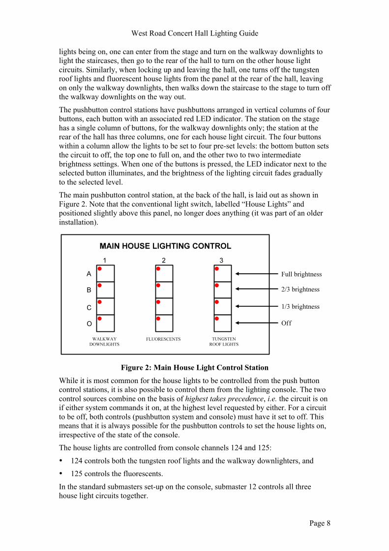
The pushbutton control stations have pushbuttons arranged in vertical columns of four buttons, each button with an associated red LED indicator. The station on the stage has a single column of buttons, for the walkway downlights only; the station at the rear of the hall has three columns, one for each house light circuit. The four buttons within a column allow the lights to be set to four pre-set levels: the bottom button sets the circuit to off, the top one to full on, and the other two to two intermediate brightness settings. When one of the buttons is pressed, the LED indicator next to the selected button illuminates, and the brightness of the lighting circuit fades gradually to the selected level. The main pushbutton control station, at the back of the hall, is laid out as shown in Figure 2. Note that the conventional light switch, labelled “House Lights” and positioned slightly above this panel, no longer does anything (it was part of an older installation).
Figure 2: Main House Light Control Station
While it is most common for the house lights to be controlled from the push button control stations, it is also possible to control them from the lighting console. The two control sources combine on the basis of highest takes precedence, i.e. the circuit is on if either system commands it on, at the highest level requested by either. For a circuit to be off, both controls (pushbutton system and console) must have it set to off. This means that it is always possible for the pushbutton controls to set the house lights on, irrespective of the state of the console. The house lights are controlled from console channels 124 and 125:
• 124 controls both the tungsten roof lights and the walkway downlighters, and • 125 controls the fluorescents.
In the standard submasters set-up on the console, submaster 12 controls all three house light circuits together.

West Road Concert Hall Lighting Guide
Page 9
3.2 Working Lights Working lights is the name given to lights that are used for staff to see what they are doing during normal day-to-day routine in the hall. They are different from the performance lighting and house lighting systems in that they are simpler, lower power systems that are relatively cheap to run and easy to maintain. Most of the time, for activities such as setting up or rehearsing a concert, the working lights should be used, not the performance or main house lights. Using the main house lights or performance lighting for such activities is unnecessarily expensive, directly in electricity, but also indirectly because the lamp life of the performance lighting units is only a few hundred hours (compared to several thousand for the working lights). As a guide:
• Working lights alone should be used at all times when the public are not present in the hall.
• The house lights may be used if necessary, e.g. if people are using or cleaning the seating areas of the auditorium.
• The performance lighting should be used only for performances or rehearsals where the lighting is important (e.g. Dress or Technical for staged productions).
There are three groups of working lights installed in the hall, each described below:
3.2.1 Rear Entrance Working Lights These are two circuits of round wall or ceiling mounted units, controlled by switches mounted near the rear door to the auditorium. One circuit has light fittings along the wall of the East balcony boxes from the rear of the auditorium to the production office. The other has similar fittings mounted on the ceiling of the corridor at the rear of the auditorium from the door to the lighting and sound control position. They are intended to allow people entering through the rear door to get to the production office or to the control position, where the walkway downlights can be turned on to illuminate the staircases to the stage.
3.2.2 Stage Working (Rehearsal) Lights There are three circuits of stage working lights, controlled from three switches in the upstage prompt side (stage left) corner of the stage, near the access ladder. The three circuits are protected by the three circuit breakers above and to the left of the switches. The switches are labelled “platform lights”. These control three sets of discharge flood lights, illuminating the stage area. Normally, all three circuits are used together to light the whole stage area. Note that, because these lights are discharge types, they take a short while to reach their full operating brightness after being switched on, typically a minute or so. Immediately after switch on, they are quite dim. It is best to be aware of this, and reassure performers that they will soon be brighter—just wait a moment. It is common for performers arriving for a rehearsal to turn on these lights, notice their relatively low intensity, and react, “These are nowhere near bright enough for us to see, we must use the performance lighting.” Not so: if one waits a couple of minutes, the working lights will provide plenty of output for rehearsal use.

West Road Concert Hall Lighting Guide
Page 10
3.2.3 “Loft” Gallery Working Lights Also controlled from a switch in the upstage prompt-side corner of the stage, these are a number of small fluorescent fittings arranged along the overhead galleries above the stage. They are only needed when working on these galleries, and otherwise should be left off. The switch is labelled “Loft Working Lights”.
3.3 Performance Lighting The performance lighting system is controlled from a Strand 300/125 console located at the rear of the hall, under a wooden roller cover to the left of controls for the sound system and air conditioning system. This controls all of the performance lighting units via 72 ways of dimmer in the dimmer room (accessed through the ceiling trap door in the corridor near the console). The performance lighting system is described in the following sections.
4 Performance Lighting
4.1 Configuration The performance lighting rig is composed of 25 Source Four Pars,750W and 12 Cantata PC 1200W units fitted with barn doors and rigged on the overhead bars, providing a combination of downlight and steep front light cover for the stage area. In addition, 8 Strand SL 15/32 600W zoom profile units, 4 of which are rigged on auditorium side bars, 2 each side, to provide fill-in front light. The following 4 SL’s are rigged on LX0 to provide spots of light for conferences, to minimise light spillage onto the screen. There are three over-stage lighting bars, each of which has an access gallery running immediately downstage of it. These bars are all at the same (fixed) height of 8.6m above the stage floor, and symmetric about the stage centre line:
• Electrics Bar Zero (LX0) is over the extended stage / row A–C area, above a fixed wooden baffle, and 9.0m long. The baffle limits the stage area that can be lit from this bar in the downstage direction to approximately half of the apron area. 10 dimmer circuits are available from 12 15A outlets on this gallery: two circuits appear at two outlets each, the others at one outlet each. 8 Source Four Par units and 4 SL Profile units are rigged along this bar.
• Electrics Bar One (LX1) is slightly upstage of the downstage edge of the fixed main stage, behind the most downstage of the two movable over stage baffles. This bar is 12.4m long, though it should be noted that approximately 2m at the prompt side end runs above the operating cables for the motorised curtains, making it difficult to rig units at this end of the bar without them fouling the cables. 10 dimmer circuits are available from 12 15A outlets on this gallery: two circuits appear at two outlets each, the others at one outlet each. 11 Source Four Par units are rigged along this bar.
• Electrics Bar Two (LX2) is slightly upstage of the mid-stage point, at 2.6m from the back wall, behind the midstage one of the two movable over stage baffles, and 12.4m long. 8 dimmer circuits are available from 10 15A outlets on this gallery: two circuits appear at two outlets each, the others at one outlet each. 6 Source Four Par units are rigged along this bar.

West Road Concert Hall Lighting Guide
Page 11
The Advance Lighting Bar 10m long, downstage of the extended stage area. This bar is a horizontal ladder beam, with the lower bar at 7.2m above the stage floor. The Advance bar has 12 dimmer circuits available from 12 15A outlets along the top bar of the ladder beam. 12 Cantata PC 1200W units are rigged on this bar. The Advance Bar is also fitted with an electronic hoist system. The Advance Bar Electronic Hoist System is hoisted down to 1.7 meters to a comfortable working height that allows easier and safer access to the lamps and connections, and also opens up safer rigging possibilities for visiting crew. The weight limit is 350 Kg evenly spread across the bar. The hoist system is operated via a control panel at the Front of House position just left of the lighting board, giving you a good sight line when operating the system. The control panel is secured via a key operated system, and the key can only be obtained from the Custodians. The hoist system must be used by competent people and must only be used when the platform area is clear. The Tallescope can be used for additional focussing and to access the bar once it is at full height. The Auditorium Side Bars are positioned above the boxes nearest the stage, and each has 6 dimmer outlets. 2 SL15/32 profile units are rigged on each side bar.
4.1.1 Lighting Plan The standard lighting plan is shown in Figure 3. A larger (full page) version of the same plan is in Appendix A. A second plan, showing the position of all the circuit outlets is in Appendix B.
Figure 3: Standard Lighting Plan

West Road Concert Hall Lighting Guide
Page 12
4.1.2 Focus Description The units on the three over-stage bars are all focussed similarly. In each case, the units are set to point slightly upstage of straight down, so that together the units on a particular bar form a continuous “wash” of downlight or steep front light. All of these bars are located above moveable wooden acoustic baffles, and the unit lower barn doors are set to just keep the light from these units from hitting the baffle, to prevent a sharp shadow line on the stage.
The units from LX0 are normally focussed to provide lighting cover at head height as far downstage as possible (limited by the wooden baffle below LX0) onto the apron stage area, and over the downstage half of the main stage. The top barn doors are set so that the upper edge of the beams lies approximately along the line where the stage floor joins the back wall, or just onto the back wall. The 4 SL15/32 profiles are positioned to create 2 specific spots for conference, (top table and lectern positions) this is to minimise light spillage onto the screen. Both spots are focussed with soft edges to balance with a soft over light.
The units from LX1 are normally focussed to provide cover from roughly directly below their bar to the back wall, with the top barn doors set so that the upper edge of the beams is about 2.5m up the back wall. The units from LX2 are normally focussed to provide extra steep downlight for the most upstage area, from approximately below their bar to the back wall. The top of the beams is allowed to hit the back wall at a height of around 5m, to provide some light on the wall or the curtains (when closed). The 12 Cantata PC units on the advance bar are divided into two sets of six, both evenly distributed along the bar. One set of six units is normally focussed to provide another layer of steep front light, similar to the over-stage bars, covering the apron area and the downstage part of the main stage that is not well lit by LX0, but with the barn doors set so as not to spill light into the row A–C well seating area. The other set of six units is focussed as downlight onto the extended stage area. From the ends of the bar, the end unit and then the next two alternate units (circuits 7, 9, 11, 14, 16 and 18) light the extended stage area. The centre pair and the alternate two outwards in each direction light the apron area (circuits 8, 10, 12, 13, 15 and 17).
The four SL15/32 profiles on each of the auditorium side bars are normally focussed to provide some front fill light for performers on the main stage and apron areas. The four units are arranged into a “fan” and set to provide soft-edged beams that blend into each other. The central two units in the fan cover the central third to half of the main stage and apron area, with the outer ones covering the outer parts. The units’ internal shutters are used to mask the light beam so that it does not light the audience. These units are not normally focussed to cover the extended stage area. When this area is in use, if front light is needed then the existing units will need to be refocused or extra units rigged at the rear of the side bars to cover the extended stage area.
4.1.3 Additional Resources The following dimmer channels are available, and are unused by the standard lighting rig. Temporary additional units may be plugged into these channels, if required. All are presented on 15A round-pin sockets.
• 4 × 10A circuits on LX2,

West Road Concert Hall Lighting Guide
Page 13
• 4 × 10A circuits on LX1,
• 4 × 10A circuits on LX0,
• 6 × 10A circuits on an old bar above the centre section of the stalls, about two thirds of the way to the rear of the auditorium. This bar has a very limited view of the stage, and so is rarely used.
• 2 × 10A circuits on each auditorium side bar
• 4 × 10A circuits on the stage floor. The same four circuits are available on both sides of the stage, but because of the wiring used to feed them, only a 5A maximum load may be drawn from each socket. Warning labels on the outlets say “1kW max load” as a reminder.
Spare lamps for the installed units, if required, can be provided by the custodians. Gel frames are available for the all the lighting units in the concert hall, they are all installed in the units and ready to go. Colour gells are not used in the standard rig: all the units are open white.
5 Basic Use of the Console The contents of this section are intended only to provide sufficient instructions to allow a person unfamiliar with the console to perform a few basic tasks:
• Turning the system on and off safely. • Using pre-programmed combinations of the performance lighting for common
concert configurations. • Making simple additions or adjustments to the pre-programmed states.
The console, a Strand Lighting 300/125, is a computerised control system whose outputs control all of the performance lighting dimmer channels and can also control the house lights. It offers many ways of controlling the lighting: this section is only scratching the surface of the console’s available facilities. The full operation manual for the GeniusPro control system from Strand Lighting should be consulted if users wish to learn more.
The console is located under a wooden roller cover at the back of the auditorium, near the sound, house light and air conditioning controls. There are two control areas covered by roller covers: the larger one on the left is the lighting console, the smaller one on the right is the sound desk. The console drives two video monitors, mounted on the brick pillar above and to the left of the console itself.
5.1 Console Layout The lighting console control surface is shown in Figure 4, with some important areas highlighted. The console is divided into two panels. The panel on the left is the submaster panel, where the 24 submaster faders are housed; the top row are numbers 1–12, the bottom row numbers 13–24. The panel on the right is the main panel, where all the other controls are. Note in particular the locations of the console LCD display and the six soft keys below it. The functions of these soft keys change, but the current functions are always indicated on the LCD above the keys. Another important group is the display control keys, in the upper centre region of the main panel. These are

West Road Concert Hall Lighting Guide
Page 14
used to switch between the different information displays that can be shown on the console video monitors.
Figure 4: Console Overall Layout
5.2 Powering On and Off At its heart, the 300 series console is a PC type computer, running special purpose lighting control software and connected to a special console control surface with custom buttons and faders. Because it is a computer at heart, it must be treated similarly to a desk-top PC, and in particular not simply switched off, but correctly shut down when no longer required.
5.2.1 Starting Up To switch on the console, first open the roller cover at the back of the auditorium, to reveal the console control surface. When the console is off, the control surface is “dead”, i.e. the buttons are not back-lit and the LCD displays within the control surface are blank. The video monitors are normally left powered on, and automatically go into low power standby when the console is shut down. In this state the power indicators, below the monitor screens, are illuminated yellow. If the monitors are completely off, with the power button not illuminated, then first switch them both on by pressing the power button (bottom right) on each one.
To start up the console, press macro button “P14” at the top right hand corner of the console. This button has the standby symbol ( ) next to it, indicating that it also starts up the console when it is off. Alternatively, the console can be started up by pressing the standby button on the front of the processor unit. To find this, hinge down the wooden panel (nearest the operator) at the front of the console support panel to reveal the console processor unit. The standby switch is the green button on the front of this unit. Briefly press this button to start up the console. The system will then power up, automatically start the Genius Pro lighting control software, and the control surface will illuminate. This process takes about 10–15s, during which first the Strand Lighting startup screen and then two standard “Live” console displays should appear. The upper monitor shows the output display, where

West Road Concert Hall Lighting Guide
Page 15
the state of all the control channels displayed. The lower monitor shows the console playback and submaster status screen.
Figure 5 and Figure 7 show the appearance of the live output and status screens. The console output may not look exactly like this, but the general layout should be similar. Note the “LIVE” heading in the centre of the top line.
Figure 5: Live Output Display (top half)
The output screen shows the current level of every channel. The white numbers are the channel numbers, and the level of each channel is shown below the channel number. If it is blank below the channel number, or shows zero, that channel is off. If there is a number shown, then the channel is on at that level. The channel levels run from zero (off) to 100 (full, displayed on the output screen as “FL”). The colour of the channel level numbers show which part of the console has control of that channel: yellow for submasters and red for the channel control (keypad). As an example, Figure 6 shows what the output screen looks like when channels 1–10 are on at level 65 and controlled by a submaster (yellow figures), and channel 32 is at full level, controlled by the channel control (red figures).
Figure 6: Example Channel Levels

West Road Concert Hall Lighting Guide
Page 16
Figure 7: Live Status Screen
The status screen shows the status information about the submasters (more about them in section 5.3, below). At the bottom of the status screen is the command area. In Figure 7, the command prompt is “LIVE: *”. This is where any commands you enter appear, and on the line below response messages from the console appear.
5.2.2 Shutting Down To shut down the console, follow this procedure:
• Press the REPORT key, in the display controls group on the main panel, to enter the console’s report screen, shown in Figure 8.

West Road Concert Hall Lighting Guide
Page 17
Figure 8: Report Screen
• Note that the soft key 2 below the LCD display on the control surface changes to be labelled “EXIT”. Press this soft key once.
• The soft keys change again. Soft key 2 now becomes “SHUT DOWN”. Press this key again.
• The console responds: “Warning: about to shut down console” on the line below the command line. Below this line it says “Hit again to confirm or CLR to cancel”. To continue the shut-down procedure, press the same soft key again. Depending on the exact internal state, a further warning may be issued, requiring another key press. If this happens, press the soft key a further time as prompted.
• The console will now shut down and the monitors will go blank. Once the monitors are blank and the control surface backlights are off, the console is shut down.
There is no need to press the standby button on the processor unit. The above procedure turns off the power automatically at the end of the shut down. You should now close the wooden covers to protect the console.
5.3 Standard State Submasters The easiest way to use the console to control the performance lighting system for normal concerts is to use the standard states that are stored in the first few submasters. The submaster faders each control a group of lights so that the brightness of these lights is increased as the fader is pushed up from the bottom of its travel. When the fader is at the bottom, that submaster is off. When at the top of its travel, the brightness is at its maximum. In between, the lights controlled are dimmed in proportion to the fader position.

West Road Concert Hall Lighting Guide
Page 18
There are 24 physical submaster faders on the submaster panel, and five “pages” of submasters. The pages are independent sets of submaster contents for the 24 submasters, any one of which may be in use at a time. The first 12 submasters, numbers 1–12 on page 1, are reserved for the pre-programmed standard states described below. Numbers 1–6 each contain an entire simple lighting state, appropriate for a particular type of concert. Normally, only one of submasters 1–6 should be used, chosen for the particular type of concert in progress. The last few submasters in the top row, numbers 8–12, contain additional groups of lights intended to be used together with one of the states from submasters 1–6.
For the standard states to be available, submaster page 1 must be selected. This should normally be the default, but if not, see section 8.1.1 below for how to change back to page 1. The current submaster page is displayed on the Live screen status page, just above the “Submaster” section, highlighted in Figure 9. If the live screen status page is not displayed, press the “Live” key in the display control section of the console to bring it up.
Figure 9: Current Submaster Page Selection
The submaster area of the status page should also show the submaster descriptions, in green text after the submaster numbers, as shown in Figure 9. If these are not shown, but the current submaster page is page 1, then the submaster configuration has been lost. See section 8.1.2 for how to restore the submaster configuration in this case.

West Road Concert Hall Lighting Guide
Page 19
5.4 Controlling Individual Channels Sometimes, it may be necessary to take control of individual channels directly, rather than only using the submasters. This can be done using the channel control section of the console: the numeric keypad and associated keys. The basic format of a channel command is as follows: “<channel number> @ <level>”, for example, to set channel 10 to 80%, type the following command:
10 @ 8 (i.e. press the keys ‘1’ then ‘0’ then ‘@’ then ‘8’) Note that you do not have to press the enter key after the command: the channel is set to 80% as soon as you press the “8” key. This is called direct 1-digit entry mode. To select 87% instead of 80%, use the decimal point key:
10 @ 8.7 sets channel 10 to 87%.
Groups of channels can be manipulated together by a similar technique, by combining channel numbers using the “+” (plus) key. To set channels 3, 5 and 17 to full on (100%), enter the command: 3 + 5 + 17 @ FULL (note that FULL is found on soft key 1).
Continuous groups of channel numbers can be specified with the THRU key, for example to set all of channels 32 to 48 to 30%, enter the command:
32 THRU 48 @ 3 Channels can be excluded from a group with the “-“ (minus) key. For example, to set channels 20 to 25 and 27 to 37 (i.e. 20–37 except 26) to 70%, enter the command 20 THRU 37 – 26 @ 7
After one of more channels have been set to a level using a command like one of the above examples, the new levels will be shown on the output screen, and the channel levels will have a red background, showing that they are under active control from the channel control. While in this state, the wheel control at the top right of the console’s main panel can be used to adjust the levels of these channels gradually while you observe the effect on the stage.
5.4.1 Turning Everything Off To turn all the performance lighting off, for example before shutting down the console at the end of an evening: • Make sure that you are in the Live screen: check for the LIVE title at the top of
the video displays. If not, press the LIVE key in the display control section of the console.
• Enter the command: 1 THRU 125 @ OFF ( i.e. press the keys ‘1’ then ‘Thru’ then ‘1’ then ‘2’ then ‘5’ then ‘@’ then ‘Off’).
• Set all the submaster faders to zero (bottom of their travel). Note that this will turn off all the channels, including the house lights, from the console. The house lights will only stay on if they are set to on from the push button control stations.

West Road Concert Hall Lighting Guide
Page 20
6 Setting Up for a Concert This section sets out the minimum procedure that an evening’s lighting operator should go through before the concert, before members of the public are admitted to the hall. Operating the lighting for a normal concert is not an onerous, specialist task, so it should be perfectly reasonable for a member of front-of-house staff to do this. This set-up procedure should be done early enough that you have time to correct any minor problems before it is necessary to open the hall to the audience, and at least half an hour before the concert start time. If you are unfamiliar with the hall’s lighting system, you may wish to start earlier to have time to experiment and familiarise yourself with the control systems.
6.1 House Lights
6.1.1 Starting from Darkness If entering the hall for the first time, with everything in darkness, go via the prompt side wing store to the sliding door at the upstage PS corner of the stage. Press the top button on the pushbutton control station. The LED next to the button will light, and the walkway downlight house lights will fade up. Walk up the stairs to the back of the auditorium, and turn on the other two house light circuits by pressing the top button in each column on the pushbutton control station mounted near the console (section 3.1.2).
6.1.2 If there are already Lights On If the hall is already open and some lights are on, go to the control position at the back of the auditorium and check that all three house light circuits are on at full brightness. On the push-button control station, the LED indicators next to the top button in each of the three columns should be lit. If not, press the top button to set that house light circuit to full brightness.
6.2 Working Lights Before members of the public are admitted, all of the working lights should be off. Working lights are designed to provide a basic, functional, cheap light source for day-to-day activities, they do not provide a particularly pleasant quality of light. Therefore, they should not be used during concerts. Check that each of the working light circuits is switched off:
• The stage working lights and loft working lights, controlled by the switches in the upstage prompt side corner of the stage (section 3.2.2 and 3.2.3).
• The rear entrance working lights, controlled from the switches near the door at the back of the auditorium (section 3.2.1). Be sure that both sets of these lights are off: the ones along the wall behind the East balcony boxes and the ones along the corridor area at the back of the auditorium. If these are not checked, it will not be obvious until the house lights are turned off at the start of the performance, when it will suddenly become embarrassingly obvious.

West Road Concert Hall Lighting Guide
Page 21
6.3 Performance Lighting If the lighting console is not already on, first it must be started up. Roll back the roller cover, and press the P14 key in the top right corner of the console to start the console (section 5.2.1).
When the console has started up, it will normally be showing the “LIVE” display screens (section 5.2.1). To ensure that the console is in its standard set-up, perform the following checks: • Set all the submaster faders to the bottom of their travel (off).
• Check, on the status display, that submaster page 1 is selected as highlighted in the screen image below. If not, select page 1 (see section 8.1.1 for how to do this).
• Check that the submaster section on the status screen shows the names of the
standard submasters in green text (similar to the screen image above). If page 1 is selected, but these are not shown, then the standard submaster settings have been lost. See section 8.1.2 below for how to restore them, or if you are unsure, consult the duty custodian.
• If any channels are shown on (at non-zero level) on the output display, set all channels to off, by entering the command
1 THRU 125 @ OFF (see section 5.4.1 if unsure how to do this). Then clear the channel selection by pressing SHIFT (the key with the Stand Lighting logo on it) and CLR.
The console is now idle, with all channels off. Bring up the stage lighting needed for your concert using one of the standard subsmasters, 1–6. These are described in section 5.3, above. Push the submaster fader corresponding to the desired concert type up to its maximum level. The stage lights will come on, lighting an area as described for the particular submaster, and the channel levels will be shown on the output display in yellow below the channels in use.

West Road Concert Hall Lighting Guide
Page 22
If you wish to add some of the additional lighting from submasters 8–11, fade the desired submasters up as high as you want them. Watch the effect of the extra light on stage as you fade up the submaster, and stop when you get to the effect that you want.
6.3.1 Taking Control of the House Lights from the Console This step is optional. If you control the houselights from the console, then you need only move one submaster fader to control all three house light circuits, instead of using the three columns of buttons on the pushbutton control station. However, it is entirely reasonable to control the house lights from the pushbutton controls during a concert if you prefer to do so.
If you want to control the house lights during your concert from the console, push submaster 12 up to its maximum level so that the console holds the house lights on. With submaster 12 set at maximum, set to house light pushbutton control station to off by pressing the bottom button in each column. The LEDs next to the bottom buttons illuminate, but the house lights stay on because they are controlled from the console.
7 Operating Lighting for a Concert
7.1 Basics Before the audience is allowed into the hall, go through the setup procedure described in section 6. At the end of this, you should have: • The house lights on (all three circuits at full).
• The working lights off. • The performance lighting on and the stage lit as required for your concert.
This section describes the basic actions needed during the concert itself. Section 7.2 describes extra actions that you may like to perform which can improve the look of your concert, but are not absolutely necessary.
7.1.1 At the Start of the Performance At the start of the concert, just before the performers come out onto the stage, you should dim the house lights. Normally, the house lights are turned completely off during the performance, but an exception is often made during choral works where the audience may wish to follow the text. To turn the houselights off completely:
• If you are controlling the house lights from the console, move submaster 12 to the bottom of its travel.
• If you are using the pushbutton controls, press the bottom button in each of the three columns.
The house lights will then automatically fade out gradually, and the performance can begin.
Alternatively, if you wish to leave enough light for the audience to follow the text, do not take the house lights completely off but instead dim them:

West Road Concert Hall Lighting Guide
Page 23
• If you are controlling the house lights from the console, move submaster 12 downwards to reduce the level of the house lights, for example to the half way point. The level of the house lights is controlled by the position of the fader, so adjust it to get the level you want.
• If you are using the pushbutton controls, press one of the two middle buttons in each of the three columns to set the house light circuits to one third or two thirds level as desired.
7.1.2 At the Interval At the interval, you need to turn the house lights back on:
• If you are controlling the house lights from the console, move submaster 12 to the top of its travel.
• If you are using the pushbutton controls, press the top button in each of the three columns.
Then, at the end of the interval, just before the performers return to the stage, turn the house lights off (or down) again as you did at the start of the first half.
7.1.3 At the End of the Performance As at the interval, at the end of the performance, after the applause, you will need to turn the house lights on, just as you did at the interval.
Once the audience has left, you should turn off the performance lighting system as described in section 5.4.1, and shut down the console as described in section 5.2.2. If there is work to be done on the stage (e.g. clearing up music stands etc.), this should be done under the working lights. The stage working lights are turned on from the upstage prompt side corner of the stage (section 3.2.2).
7.2 Optional Extras This section describes further lighting options that can be used in addition to the basic steps already described, to improve the look of your concert.
7.2.1 Dimming the Stage Lighting when No-one is on Stage When there is no-one on stage, before the start of the performance, during the interval and at the end while the audience leaves, you can dim down the stage lighting to avoid having the empty space brightly lit and drawing attention. To do this, simply reduce the levels of whichever submasters 1–11 you are using. You can see the effect on the stage, and dim as much or as little as you like, but reducing the levels by about 30% is suggested as a starting point.
7.2.2 Adding Front Light for Curtain Calls. During the applause at the end of a concert, soloists or conductors often come downstage nearer the audience to take their bows. It is useful to add more front-light at this time so that their faces are well lit, and can be clearly seen by the audience. This can be done by fading up either submaster 10 or 11, depending on how much of the stage width is in use. Submaster 10 lights only the central section, as used with main state submasters 1–3, submaster 11 lights the full width of the stage.

West Road Concert Hall Lighting Guide
Page 24
Strong front light is not normally used during concerts, because it can tend to dazzle the performers, e.g. making it hard for them to see the conductor, but at the end of a performance this is not an issue.
7.2.3 Entrance / Exit Light If you are lighting a small concert, e.g. a single soloist or small ensemble, then it is normal only to light a relatively small area of the stage. However, this leaves the area between the doorway on prompt side and the central lit area, through which the performers enter and exit, dark. Submaster 8 controls light on this entry / exit route, so by fading up this submaster you can provide some light in this area at the times when it is needed.
7.2.4 Putting It All Together As an example, suppose you are operating the lighting for a string quartet concert, and wish to use all the facilities described. Here’s what you might do: 1. Set up the hall as described in section 6 before the concert, including taking
control of the house lights from the console (section 6.3.1) so that you can then do everything from the console. Use submaster 2 for a quartet concert, and add a bit of submaster 9 (at 30%, say), just to put some light on the back wall.
2. While the stage is empty, you keep the level of submaster 2 at say 60%. This has some light on the stage, but not too bright.
3. At the start of the concert, dim the house lights to zero by fading submaster 12 to zero.
4. Just before the performers enter, increase the main stage state (submaster 2) to full, and fade in some of the entrance light (submaster 8), to say 60%.
5. Once the performers are ready to begin, fade out the entrance light (submaster 8).
6. Nothing else to do until the interval. 7. If there is applause at the end of the first half, fade in some front light on the stage
centre area (submaster 10), and at the same time fade up some light on the entrance/exit route (submaster 8). Leave these and the main state (submaster 2) up until you are sure that the performers are not going to come out again to take more applause.
8. Once the applause subsides, bring up the house lights by fading up submaster 12. At about the same time, or just afterwards, fade out the front light (submaster 10) and entrance light (submaster 8), and reduce the main state (submaster 2) to its lower level that you used before the start.
9. Repeat the entire process from step 3 onwards for the second half. 10. When the audience have left at the end of the concert, turn off the performance
lighting and shut down the console. If necessary, turn on the stage working lights to allow the stage to be cleared, and set the house lights to on from the pushbutton control station.

West Road Concert Hall Lighting Guide
Page 25
8 Troubleshooting This section gives procedures for restoring the console to its standard state, with the submaster contents described above available. It is not within the scope of this guide to provide a complete description of everything that could possibly be changed in the console, and how to correct it. Instead, procedures for restoring the submaster settings and, if necessary, the entire standard configuration from saved disc files are described.
The most common cause of the console state being unexpected is that an incoming company have used some of its more advanced facilities, not described here, and left it configured slightly differently. In most cases, the procedures given will return the console to its standard state relatively easily. These should be sufficient to get the state of the system back to as described in most cases, but if it still does not behave as expected after this, specialist help is probably required.
8.1 Restoring the Standard Submasters If the submasters do not seem to control the standard states as described in this guide, then the most likely causes are either that another submaster page is selected, or the submaster contents have been reprogrammed. Both of these can be corrected relatively easily.
8.1.1 Selecting the Correct Submaster Page To check that the submaster page containing the standard submaster contents is selected, press the LIVE key in the display control section to return to the console’s live display. On the status screen, check the submaster page display as shown highlighted in Figure 9 above.
If a page other than page 1 is selected, first set all the submaster faders to zero (bottom of their travel), then change to page 1 by using
SUB + (i.e. the “SUB” key followed by the “+” key) or SUB – (i.e. the “SUB” key followed by the “-“ key)
to change the submaster page. SUB + increments the page number, SUB – decrements it. If you increment it from the maximum, it will wrap back to page 1.
8.1.2 Restoring Submasters from Disc If submaster page 1 is selected, but the standard submaster settings are not present, i.e. either the state names (in green text) do not appear to the right of the submaster numbers on the live status screen, or the states that come on (if any) when the submaster is faded up are not as expected, then it is most likely that the submaster contents have been reprogrammed. This section tells you how to restore the standard submaster contents from the console’s internal local disc.
Enter the archive screen, by pressing the ARCHIVE key on the display control panel of the console main panel. The archive screen is shown in Figure 10. The standard setup file is called WR Standard (West Road Standard), and is stored on the local hard drive (drive C:).

West Road Concert Hall Lighting Guide
Page 26
Figure 10: The Archive Screen First, the correct file to load must be selected. In the centre of the screen, on the left hand side, check that it says “Local Disk” in the red box, as shown in Figure 10, and that further along the same line is gives the current directory as “C:\shows”, also as shown in Figure 10. If either of these is not the case, it will be necessary to select the correct directory on the local disc as follows.
If the red box does not say “Local Disk”, change to the local disc, as follows: • Press soft key 3, which is labelled “Browse Files”. Notice that, in the file system
area, the lower half of the archive screen under the headings “Show”, “Cues”, “Date” etc. a red highlight bar appears.
• Move the red highlight bar down to the line that starts “(C:)”, as in Figure 11, by using the trackball, and then press the “*” (enter) key. This selects the local disc. It will now say “Local Disk” in the red box as in Figure 10.

West Road Concert Hall Lighting Guide
Page 27
Figure 11: Selecting "C:" Once the local disc is selected, check the current directory, displayed on the middle line of the archive screen, is C:\shows, as in Figure 10. If not, you must change to this directory as follows:
• If you do not already have the red highlight bar in the file system area, press the “Browse Files” key (soft key 3) to get it. If you had to change to the local disc, the highlight bar is already there.
• If the top line of the file system area shows “[..]”, i.e. two dots between square brackets, put the red highlight on this line using the trackball, then press the enter (“*”) key. Repeat this step, i.e. select “[..]” and press enter until “[..]” no longer appears at the top of the file system area. This means you have reached the top level in the file system.
• Now, move the red highlight bar to the line which begins “[shows]” in the file system area, again using the trackball, then press the “*” key. This selects the shows directory.
The line in the middle of the archive screen should now look like that in Figure 10: the red box containing “Local Disk” and the current directory shown as “C:\shows” Next, select the file that is to be loaded, i.e. WR_Standard.
• If you do not already have the red highlight bar in the file system area, press the “Browse Files” key (soft key 3) to get it. If you had to change to the local disc, or select the correct directory, then the highlight bar is already there.
• Using the trackball, move the red highlight bar to the line that begins “WR_Standard”, then press the “BACK” key (soft key 6). This selects the correct file to be loaded and leaves the file system area.

West Road Concert Hall Lighting Guide
Page 28
Towards the bottom of the archive screen, roughly half way across, under the heading “Show to Load/Copy/Delete/Restore”, the screen should now show “WR_Standard”, as it does in Figure 10. Next, it is necessary to specify what information is to be loaded from the file. To load just the submaster configuration, use the trackball to move the small, red square cursor to the line just to the left of the word “Submasters”, then press the “+” key to select this field. A white tick symbol appears in the red box, as highlighted in Figure 12.
Figure 12: Selecting "Submasters" in Archive
Check that, on this same line, it says “ALL” in the “PAGE” column, “__1” in the “FIRST” column and “_24” in the “LAST” column, as in Figure 12. If any of these are incorrect, move the red box over the offending item, and set it to the correct value. The values are changed by pressing the “+” key to increase, and the “-“ key to decrease. Once there is a tick next to Submasters, and the rest of the line reads “ALL __1 __24” as shown in Figure 12, press the “Load Show” key (soft key 2). The console will prompt “Hit again to confirm or CLR to cancel” in the bottom line of the archive display. Press the same key again to confirm the operation. The states will now be loaded from the local disc. You may see a “Please Wait…” message near the bottom of the screen while the information is loaded. Once this disappears, return to the Live screen by pressing the “LIVE” key in the display control section. The standard submaster contents should now have been restored.
8.2 Restoring the Entire Console Configuration If the console configuration in general has been changed, so that the displays are not as expected, or it is behaving strangely in some way, the easiest thing to do is to restore the entire console state from the standard settings file. The procedure to do this is very similar to that for restoring only the submasters, described above.
West Road Concert Hall Lighting Guide
Page 29
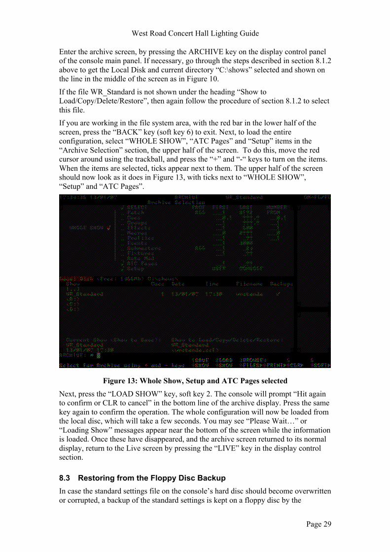
Enter the archive screen, by pressing the ARCHIVE key on the display control panel of the console main panel. If necessary, go through the steps described in section 8.1.2 above to get the Local Disk and current directory “C:\shows” selected and shown on the line in the middle of the screen as in Figure 10.
If the file WR_Standard is not shown under the heading “Show to Load/Copy/Delete/Restore”, then again follow the procedure of section 8.1.2 to select this file. If you are working in the file system area, with the red bar in the lower half of the screen, press the “BACK” key (soft key 6) to exit. Next, to load the entire configuration, select “WHOLE SHOW”, “ATC Pages” and “Setup” items in the “Archive Selection” section, the upper half of the screen. To do this, move the red cursor around using the trackball, and press the “+” and “-“ keys to turn on the items. When the items are selected, ticks appear next to them. The upper half of the screen should now look as it does in Figure 13, with ticks next to “WHOLE SHOW”, “Setup” and “ATC Pages”.
Figure 13: Whole Show, Setup and ATC Pages selected
Next, press the “LOAD SHOW” key, soft key 2. The console will prompt “Hit again to confirm or CLR to cancel” in the bottom line of the archive display. Press the same key again to confirm the operation. The whole configuration will now be loaded from the local disc, which will take a few seconds. You may see “Please Wait…” or “Loading Show” messages appear near the bottom of the screen while the information is loaded. Once these have disappeared, and the archive screen returned to its normal display, return to the Live screen by pressing the “LIVE” key in the display control section.
8.3 Restoring from the Floppy Disc Backup In case the standard settings file on the console’s hard disc should become overwritten or corrupted, a backup of the standard settings is kept on a floppy disc by the

West Road Concert Hall Lighting Guide
Page 30
custodians. If the WR_Standard file cannot be found on the local hard disc, or if after the whole configuration has been reloaded as described above the console still does not behave as expected, then the configuration can be restored from this backup floppy disc. After doing this, the standard configuration file should be re-saved to the local hard disc. The procedure to load the entire configuration from the floppy disk is similar to that for loading it from the hard disk, described above. Start by entering the archive screen, by pressing the ARCHIVE key on the display control panel of the console main panel. Insert the backup floppy disk into the console’s floppy disk drive, which is on the front of the processor unit (near the standby switch). The floppy disk must then be selected as the file system to use. This is shown in the centre of the archive screen, on the left hand side, the red box where it usually says “Local Disk”. To select the floppy disk:
• Press soft key 3, which is labelled “Browse Files”. In the file system area, the lower half of the archive screen under the headings “Show”, “Cues”, “Date” etc., the red highlight bar appears.
• Move the red highlight bar down to the line that starts “(A:)” by using the trackball, then press the “*” (enter) key. This selects the floppy disc. It will now say “Floppy Disk” in the red box.
Then select the file WR_Standard by again moving the red bar with the trackball to highlight this line, and then press the “BACK” key, soft key 6. Under the heading “Show to Load/Copy/Delete/Restore”, it will now show “WR_Standard”. To load the entire configuration from this file, the procedure is the same as loading it from the local disk. Select “WHOLE SHOW”, “ATC Pages” and “Setup” items in the “Archive Selection” section, the upper half of the screen by moving the red cursor around using the trackball, and press the “+” and “-“ keys to select the items. When the items are selected, ticks are shown next to them. The upper half of the screen should now look as it does in Figure 13, with ticks next to “WHOLE SHOW”, “Setup” and “ATC Pages”.
Next, press the “LOAD SHOW” key, soft key 2. The console will prompt “Hit again to confirm or CLR to cancel” in the bottom line of the archive display. Press the same key again to confirm the operation. The whole configuration will now be loaded from the floppy disc, which will take a few seconds. You may see “Please Wait…” or “Loading Show” messages appear near the bottom of the screen while the information is loaded. Once these have disappeared, and the archive screen returned to its normal display, return to the Live screen by pressing the “LIVE” key in the display control section. You can now remove the floppy disc from the drive and return it to storage.
8.3.1 Copying the Configuration to the Local Disk If you have had to restore the configuration from the backup floppy disc, once you have confirmed that the console has returned to normal, and operates as expected, it is a good idea to save a copy of the configuration to the local disc. To do this, go to the Archive screen and change the current file system back to the local disk and the current directory back to “C:\shows” as described in section 8.1.2, but do not load anything from the local disk. The archive screen should again look like Figure 10 at

West Road Concert Hall Lighting Guide
Page 31
this point, with “Local Disk” shown in the red filesystem box and “C:\shows” further along the same line.
To save the entire configuration, select “WHOLE SHOW”, “ATC Pages” and “Setup” in the archive selection section, so that there is a tick next to each, as in Figure 13. Check that under the heading “Current Show (Show to Save)” near the bottom left hand corner of the screen, it shows “WR_Standard”. If another filename is shown, Press the “TEXT” key, and type the name “WR_Standard” on the ordinary QWERTY keyboard connected to the console, and then press the “*” key. Then press the “SAVE SHOW” key, soft key 1. The console prompts you with “About to Save to Local Disk. Hit again to confirm to CLR to cancel.” Press the same key again to confirm the operation. The message “Save Completed” will appear after a few seconds when the configuration has been saved.
Press the “LIVE” key to return to the Live screens.
9 Programming and Storing Submasters This section describes how to create or change the states that are programmed into the submasters. The states programmed into the standard submasters, submasters 1–12 on page 1, may only be changed by custodians or with explicit permission from the concert hall management, but the others, including submasters 13–24 on page 1, may be programmed by users if desired.
If would like to use additional submasters along with the standard ones, then numbers 13–24 are available on the same page, page 1, as the standard states. Alternatively, for concerts or shows that will not use the standard submasters at all, all of pages 2–5 are available for use and may be freely reprogrammed according to your requirements. Section 8.1.1 describes how to change submaster pages.
9.1 How to Programme a Submaster There are many ways to programme submasters, or to view or alter their contents. For a full description, refer to the GeniusPro operator’s manual from Strand Lighting. This section covers only how to record the lighting state currently on the stage into a submaster.
To record the current state of the lighting, as seen on the stage, into a submaster, press the “SUB” key, then press the “bump button” below the submaster fader that you wish to programme. The bump buttons are the black buttons with an illuminated area in the centre. This replaces the previous contents of that submaster with the current on-stage lighting state. For example, suppose you with to programme submaster 15 to have channel 20 at full, and channel 19 at 70%. You could do this as follows: • Turn off all channels: set all the submasters to minimum and enter the command
1 THRU 125 @ OFF. • Set the channels you want to the levels you want. In this example, you would
enter: 20 @ FULL
19 @ 7

West Road Concert Hall Lighting Guide
Page 32
• Record this state into submaster 15 by pressing the “SUB” key then pressing the bump button below submaster fader 15.
9.2 How to Save Submaster Settings to Disc This section explains how to save the submaster settings to the console’s local disk. The standard setup file, WR_Standard, may only be overwritten or updated by the custodians, or with the express permission of the concert hall management. However, you may save your settings to another file name without restriction, though obviously it is polite not to overwrite someone else’s files.
To save the current submaster settings, enter the archive screen by pressing the “ARCHIVE” key in the display control panel of the console main panel. The archive screen is shown in Figure 10. The standard setup file is called WR_Standard (West Road Standard), and is stored in the “shows” directory on local hard drive (drive C:), take care not to overwrite this file accidentally. Enter a name for the file that you will save, by pressing the “TEXT” key, then typing in the name on the standard QWERTY keyboard and pressing the “*” key. Names may not contain spaces and may only contain the letters a–z , A–Z, numbers 0–9 and the underscore character,”_”. Check that the name you entered appears under the heading “Current Show (Show to Save)” on the archive screen.
Next, select submasters as the item to be saved, use the trackball to move the small, red square cursor to the line just to the left of the word “Submasters”, then press the “+” key to select this field. A white tick symbol appears in the red box, as highlighted in Figure 12.
Now press the “SAVE SHOW” key, soft key 1. The console prompts you with “About to Save to Local Disk. Hit again to confirm to CLR to cancel.” Press the same key again to confirm the operation. The message “Save Completed” will appear after a few seconds when the configuration has been saved.
You can then restore your submaster settings at a later time by following the procedure in section 8.1.2, but selecting the file that you saved, rather than “WR_Standard” to be loaded

Appendix A A full page version of the standard lighting plan is given on the next page.


Appendix B A full page plan showing the positions of the stage lighting and associated circuit outlets is given on the next page.
In the plan, the circuits are shown as follows:
S23 Stage lighting circuit 23
P3 Platform working lights outlet 3
T 15A test socket
Q Circuit Q outlet. These 15A sockets are switched from the USPS corner.