Embed Size (px)
Citation preview

LFII UNIT& CHAIRMOUNT
LFCBII & LFWII
LFTII & LFTII-D
LFCII &LFCII-D
LIGHTFANTASTIC® II, III
Use & Care
LFCIII, LFCIIID LFIII &
LFTIII, LFTIIID
LFCBIII, LFWIII

- 2 -
INTRODUCTION ......................................................................................................................................... 3
Definitions of Symbols .......................................................................................................................... 3
Equipment Disposal .............................................................................................................................. 3
IEC Classifications................................................................................................................................ 3
TECHNICAL DATA ...................................................................................................................................... 4
TABLE OF PRODUCT SYMBOLS.............................................................................................................. 4
FAMILIARIZATION
All Models ......................................................................................................................................... 5-6
Optional Remote Activation .................................................................................................................. 6
Track Lights .......................................................................................................................................... 7
Ceiling Lights ........................................................................................................................................ 8
Wall & Cabinet Mounted Lights ............................................................................................................. 9
OPERATION ..............................................................................................................................................10
MAINTENANCE & ADJUSTMENTS
Cleaning Plastic Shield (All Models) ....................................................................................................11
Cleaning Reflector (All Models) ............................................................................................................12
Focusing Light (All Models) .................................................................................................................13
SpringTension Adjustment (All Models) ...............................................................................................14
Arm Friction Adjustment (All Models) ...................................................................................................14
Bushing Lubrication (LFII Unit Mount Light) ..........................................................................................14
Yoke Pivot Friction Adjustment (All Models) .........................................................................................15
Knuckle Elbow Friction Adjusment (Wall & Cabinet Mounted Lights) ...................................................15
Knuckle Joint Adjustment (LFII Unit Mount Light) .................................................................................16
3rd-Axis Friction Adjustment (Ceiling & Track Lights) ............................................................................16
Single & Dual Track Mounted Light s Trolley Adjustment ......................................................................17
Arm Joint Tension (Ceiling & Track Lights) ..................................................................................... ......17
Adjustment of Column Stop Position (Ceiling & Track Lights) ..............................................................17
PARTS REPLACEMENT ...........................................................................................................................18
TABLE OF CONTENTS

- 3 -
INTRODUCTION
Definitions of SymbolsThe following symbols may be used throughout this manual:
CAUTION. Failure to carefully follow the described procedure may result in damage to theequipment.
WARNING. Failure to carefully follow the described procedure may result in damage to theequipment and the operator.
Risk of electrical shock present. Make sure power is disconnected before attempting thisprocedure.
ObtainingTechnical Literature: The manufacturer will make available on request circuit diagrams,component parts lists, descriptions, calibration instructions or other information that will assist theuser’s technical personnel to carry out repair and replacement of serviceable equipment.
Equipment Disposal: No risks are present concerning the disposal of this type of equipment.Whenever possible, the manufacturer strongly recommends the recycling or reuse of all materialused in the manufacture of this product.
IEC Classification
WARNING:Only authorized service techniciansshould attempt to service this equipment. Useof other than authorized technicians will voidthe warranty.
These products comply with the followingproduct regulatory standards:– UL 2601-1, EN 60601-1– CAN/CSA C22.2 No.601-1, M97
Degree of protection against electri-cal shock
–Type B Equipment– Class 1
– IPX 4Degree of protection against ingressof liquid
Ordinary
Mode of Operation(INT) Intermittent- 30 seconds ON,3 minutes OFF
The dental light is classified as a Class 1 product under rule 1 ofAnnex IX of the MDD 93/42/EEC.

- 4 -
POWER SUPPLYPrimary SpecificationsforTransformerVolts Cycles Amps117 VAC 60 Hz. 1.5 A ~240 VAC 50-60 Hz. .75 A ~
Secondary Power SupplyVolts Cycles Amps23/21/19 VAC 50/60 HZ 5.5/5/4.5 A ~
TECHNICAL DATA
TABLE OF PRODUCT SYMBOLS
Groun
Alternating Current
Protected against splashing water
Type B equipment (specifiesdegree of protection againstelectric shock)
Safety NotesThis unit is not to be used in rooms where an explo-sion hazard exists.The pre-installation must be performed according tothe requirements in our ‘Pre-installation Instructions’.As manufacturers of electro-medical products we canassume responsibility for safety-related performanceof the equipment only if maintenance, repair andmodifications are carried out only by us or agencieswe have authorized for this purpose, and if compo-nents affecting safe operation of the unit that may beneeded are replaced with original parts.We suggest that you request a certificate showingthe nature and extent of the work performed, fromthose who carry out such work, and specify that thecertificate show any changes in rated parameters orworking ranges, as well as the date, the name of thefirm and a signature.For reasons of product safety, only original Pelton& Crane accessories approved for this product, oraccessories from third parties which have beenreleased by Pelton & Crane may be used. It is theuser’s risk whenusing non-released accessories.
d
HOT SURFACE
Intensity control
OFF
ON
Attention: consult accompanyingdocuments

- 5 -
Light Fantastic® II & III System Overview
Intensity ControlSwitch
ON/OFFToggleSwitch
LFII & LFIII Unit & Chair Mount
IntensityControl Switch
ON/OFFToggle Switch
LFCBIII, LFWIII, LFCBII & LFWIICabinet & Wall Mount
IntensityControl
IntensityControl
LFTIII, LFTII-D, LFTII & LFTII-DTrackMount
LFCII & LFCII-DCeilingMount
ON/OFFToggle Switch
ON/OFFToggle Switch
Light HandleLight Handle
Light Handle
Light Handle
LightReflectorLight
Reflector
LightReflector
LightReflector
LFCIII, LFCIII-D,

- 6 -
FAMILIARIZATION (All Models)
Optional Remote Activation: (Models: LFC,LFT, LFW & LFCB)
The optional electronic touch pad allowsthe user to activate the light by depressingthe light symbol button. The toggle switchon the light head must be in the ONposition for this function to operate.Remote activation is not available for thedual track, dual ceiling or the 240 VACunits.
NOTE:The touch pad will operate only ifthe power supply has been installed andconnected and is only applicable with thePelton & Crane 1500 and 2005 chairs.
ON/OFFToggle Switch
ON/OFF LightButton
RemoteActivationTouch Pad
WARNING: The plastic shields preventwater spray from splashing on theglass reflector and lamp. Do not
operate light unless plastic shields are inplace. Shields provide protection in case oflamp explosion.
Reflector: The dichroic-coated reflector reflectsdesired light and allows unwanted heat to passthrough the back. The shape of the reflectorcollects light from a wide angle and produces ahigh intensity glare free pattern approximately3” (7.6 cm) to 8” (20.3cm) wide of distancesfrom 18” (45.7cm) to 36” (91.4cm). Each part ofthe reflector becomes a light source, whichcontributes to the total pattern. The large sizeof usable pattern requires less light headrepositioning during an operation. The reflectoralso offers other demonstrative advantagessuch as greater energy efficiency, cooler lightand increased lamp life.
Lamp: The miniature quartz halogen lamp lastsmany times the life of conventional lamps. Itsself-cleaning process maintains constant lightintensity. The lamp may be replaced in secondsand requires no tools. Refer to the “Mainte-nance and Adjustments” section for lampreplacement.
CAUTION: The handle and the lighthead become very hot during
operation. Do not touch these areas while lightfunctioning.
Reflector Lamp
PlasticShield
PlasticShield is

- 7 -
LFTThe track lights answer the demand forprecise oral cavity lighting required for supineoperative procedures. The dual track light isoffered for dentists needing two intraorallights. One light may be placed over the headand the other in front to overcome difficultlighting conditions. Variable length columnsare available to accommodate 8' (2.44 m) to13' (3.97 m) ceiling height installations.
Track Assembly: The track assembly con-sists of a plywood pallet, an aluminum trackchannel, aluminum dress covers, panels andend caps. Proper installation to ceiling sub-structures will ensure drift-free and vibration-free operation of the light head.
Transformer Box: A fuse located on the endof the transformer is provided for circuitprotection of the light. The single track lightrequires a 3AG SLOW BLOW, 2 amp, 125 Voltfuse (little-fuse #313002/S). The dual tracklight requires a 3AG SLOW BLOW, 4 amp,125 Volt fuse (little-fuse #313004/S).
Trolley: The trolley rolls freely at the touch ofthe hand and serves as the portable andpositive mount for the light column throughwhich the electrical wiring passes.
Vertical Column: The column length andassociated power cable determine heightoflight and are the only two variable factors withdifferent ceiling heights. If light is moved to anew office with a different ceiling height, anew column and associated power cable maybe purchased to easily modify the light.
Column Stop: The entire arm and light maybe rotated approximately 322° with respect tothe column. Location of the column stop maybe varied to provide optimum operatingpositions. To adjust, refer to the "Maintenance& Adjustments" section of this manual.
CAUTION: Do not rotate arm morethan 360° with respect to thecolumn or twisting damage to the
internal wiring may result.
FAMILIARIZATION (Track Lights)LFTII SingleTrack
LFTII DualCeiling Light
TrackAssembly
Trolley
TransformerBox
Column
TransformerBox & Fuse
Column
Trolley
TrackAssembly
Column Stop

- 8 -
LFCThe ceiling lights answer the demand forprecise oral cavity lighting required forsupine operative procedures. The dualceiling light is offered for dentistsneeding two intraoral lights. One light maybe placed over the head and the other infront to overcome difficult lighting condi-tions. Variable length columns are avail-able to accommodate 8' (2.44 m) to 13'(3.97 m) ceiling height installations.
Transformer & Fuse: A fuse located onthe end of the transformer is provided forcircuit protection of the light. The singleceiling light requires a 3AG SLOW BLOW,2 amp, 125 Volt fuse (little-fuse #313002/S). The dual ceiling light requires a 3AGSLOW BLOW, 2 amp, 125 Volt fuse (little-fuse #313004/S) in each arm.
Vertical Column: The column length andassociated power cable determine heightof light and are the only two variablefactors with different ceiling heights. Iflight is moved to a new office with adifferent ceiling height, a new column andassociated power cable may be pur-chased to easily modify the light.
Column Stop: The entire arm and lightmay be rotated approximately 322° withrespect to the column. Location of thecolumn stop may be varied to provideoptimum operating positions.
CAUTION: Do not rotate armmore than 360° with respect tothe column or twisting damage
to the internal wiring may result.
FAMILIARIZATION (Ceiling Lights)LFCIISingleCeiling Light
Column
Transformer& Fuse
CeilingMount
LFCII-D DualCeiling Light
CeilingMount

- 9 -
LFCB & LFWTwo models of the wall & cabinet mountedlight are available. They come with two armsections plus a down arm section at the frontknuckle. It extends 59" (149.9 cm) from themounting box to the centerline of the lighthead handle.
Transformer Box & Fuse: A fuse located onthe end of the transformer is provided forcircuit protection of the light. The wallmounted light requires a 3AG SLOW BLOW,2 amp, 125Volt fuse (little-fuse #313002/S).
Column Stop: The entire arm and light maybe rotated approximately 322° with respect tothe column. Location of the column stop maybe varied to provide optimum operatingpositions. To adjust, refer to the "Mainte-nance & Adjustments" section of thismanual.
CAUTION: Do not rotate arm morethan 360° with respect to the columnor twisting damage to the internal
wiring may result.
FAMILIARIZATION (Wall & CabinetMounted Light)LFWII &LFCBII Light
Arm Sections
DownArm
TransformerBox& Fuse

- 10 -
OPERATION
CAUTION: Do notforceand/or rotate arm morethan 360° with respect tothe column or the head
with respect to the arm. Doing socould cause damage to the mechani-cal stop(s) and or the wiring, resultingin potential twisting damage and/orshorting of the internal wiring.
Position light head approximately 18"(45.7 cm) to 36" (91.4 cm) from the oralcavity. Reposition light head as requiredduring the operation procedure.
NOTE:The lamp focus is factory set foran optimum pattern at distances of 18"(45.7 cm) to 36" (91.4 cm). If furtherfocusing is required, refer to the“Mainte-nance andAdjustments”section, Focus-ing Lamp.
Set intensity control for desired intensity.
NOTE:The lamp life may be extended, inaddition to conserving energy, when theintensity control is used onthe lowestsetting.
Activate the light by switching toggle toright to turn light on. Light will remain onuntil operator switches the toggle to themiddle position to turn light off.Turn lightoff when illumination is not required.The lamp is affected only by operatingtime and not by turning it on or off. Leavelight off when possible for longer lamplife, less power consumption and cooleroperation.
Optional RemoteActivation: Toactivate the light, switch the ON/OFFtoggle on the light head to the ONposition. Depress the remote activationtouchpad light symbol button to activatelight. Light will remain on until the buttonis depressed to deactivate the light.Thelight's ON/OFF toggle must be ON forthis function to operate.
ON/OFF Switch
Light SymbolButton
RemoteActivationTouch Pad
IntensityControl

- 11 -
Cleaning Plastic Shields (All Models)
The LF has two plastic shields. Both plasticshields may be removed for cleaning.To removeplastic shields, the following procedure shouldbe performed:
WARNING:To avoid burningfingers or hand, ensure lamp isoff and cool.
• Open rear of light by depressing small pin onside of light frame.
• Gently squeeze one side of plastic shield tobe cleaned until edge is inside the frameretaining edge.
• Remove by pushing plastic shield throughback side of light.
• Wash the shield in a mild detergent and water,and dry with soft cloth. The plastic shield isunbreakable but may be easily scratched.
• Replace plastic shield by placing one side ofplastic shield in position behind the frameretaining edge with edge of shield againstretaining bosses. Push other side straightdown until shield snaps in place.
WARNING: Do not operate lightunless plastic shields are inplace. Shields provide protec-tion In case of lamp explosion.
WARNING: Dispersion plate/reflector should be checkedfollowing cleaning to ensureproper placement and fit.
Plastic Shield
Plastic Shield
Retaining Edge
RetainingBosses
Retaining Edge
MAINTENANCE & ADJUSTMENT S

- 12 -
Cleaning Reflector (All Models)
The LF is a precise optical instrument thatwhen properly cared for will provide years oftrouble-free operation. The front of the reflectorshould be cleaned no more than every sixmonths for optimum performance. For normalcleaning, the following procedure shouldbeperformed:
CAUTION: Do notuse abrasives,chlorine or ammonia whencleaning reflector. Do not rub
heavily. Do not clean when reflector is hot.Do not soak in cleaning solution. Do notroutinely clean front of reflector at morefrequent intervals than specified. Failure tocomply with any of the above cautions canresult in degradation of the optical coating.
• Saturate clean, soft, lint-free cloth with 50%of isopropyl alcohol and 50% of distilledwater.
• Wipe reflector in lengthwise direction only(*), never from side to side.
• Use clean, dry cloth and wipe lightly in thesame direction to remove all alcohol.
The rear surface of the reflector may becleaned as necessary using a soft clothdampened with a mild detergent.Take care notto permit cleaning solution to contact frontsurface.
*
Reflector
MAINTENANCE & ADJUSTMENT S
- 13 -
MAINTENANCE & ADJUSTMENT
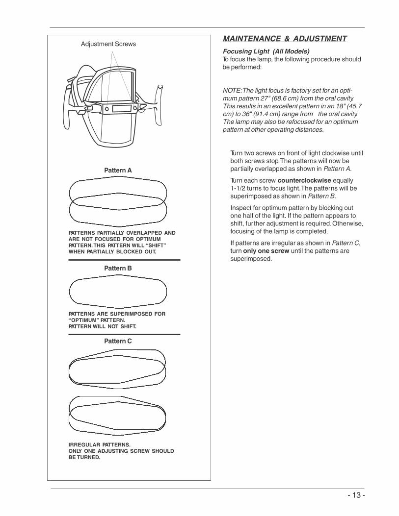
Focusing Light (All Models)To focus the lamp, the following procedure shouldbe performed:
NOTE:The light focus is factory set for an opti-mum pattern 27" (68.6 cm) from the oral cavity.This results in an excellent pattern in an 18" (45.7cm) to 36" (91.4 cm) range from the oral cavity.The lamp may also be refocused for an optimumpattern at other operating distances.
Turn two screws on front of light clockwise untilboth screws stop.The patterns will now bepartially overlapped as shown in Pattern A.
Turn each screw counterclockwise equally1-1/2 turns to focus light.The patterns will besuperimposed as shown in Pattern B.
Inspect for optimum pattern by blocking outone half of the light. If the pattern appears toshift, further adjustment is required.Otherwise,focusing of the lamp is completed.
If patterns are irregular as shown in Pattern C,turn only one screw until the patterns aresuperimposed.
Pattern A
Pattern B
Pattern C
PATTERNS PARTIALLY OVERLAPPED ANDARE NOT FOCUSED FOR OPTIMUMPATTERN.THIS PATTERN WILL “SHIFT”WHEN PARTIALLY BLOCKED OUT.
PATTERNS ARE SUPERIMPOSED FOR“OPTIMUM” PATTERN.PATTERN WILL NOT SHIFT.
IRREGULAR PATTERNS.ONLY ONE ADJUSTING SCREW SHOULDBE TURNED.
Adjustment Screws

- 14 -
There are two adjustments that can be madeafter the light is installed and all wiringconnections arecompleted.
SpringTension Adjustment (All Models)
Over a period of time and usage, spring tensionadjustment to the rear arm may be necessary ifthe arm drifts downward.
NOTE: The spring lift force is sensitive to screwrotation. When adjusting, use 1/4 turn incre-ments.
1. Straighten reararm and insert a 5/16” handle-hex wrench through hole in reararm collar.
2. Turn wrench clockwise to increase lift force ofarm or counterclockwise to decrease lift force.
Arm Friction Adjustment (All Models)NOTE: Once spring is counterbalanced, frictionadjustment may be necessary.If up-drift or down-drift occurs, tighten set screw(clockwise) with a 9/64" hex wrench through thefriction adjustment hole. Do not over tighten.
Bushing Lubrication Model: (LFII & LFIII Unit MountLight Only)Apply a thin coat of lubrication to outside ofbushing surface every 12 months. Lift lightcolumn to apply lubrication.
CAUTION: Failure to apply lubricantmay cause bushing to bind in tube
and unscrew itself from the rear arm to light.
Structural InspectionPeriodically, inspect the light to ensure that allstructural components are intact and that allfasteners are tight.
Set screw
MAINTENANCE & ADJUS TMENT
LightColumn
Bushing Surface
Rear Arm
5/16" Wrench Collar
- 15 -
MAINTENANCE & ADJUS TMENT
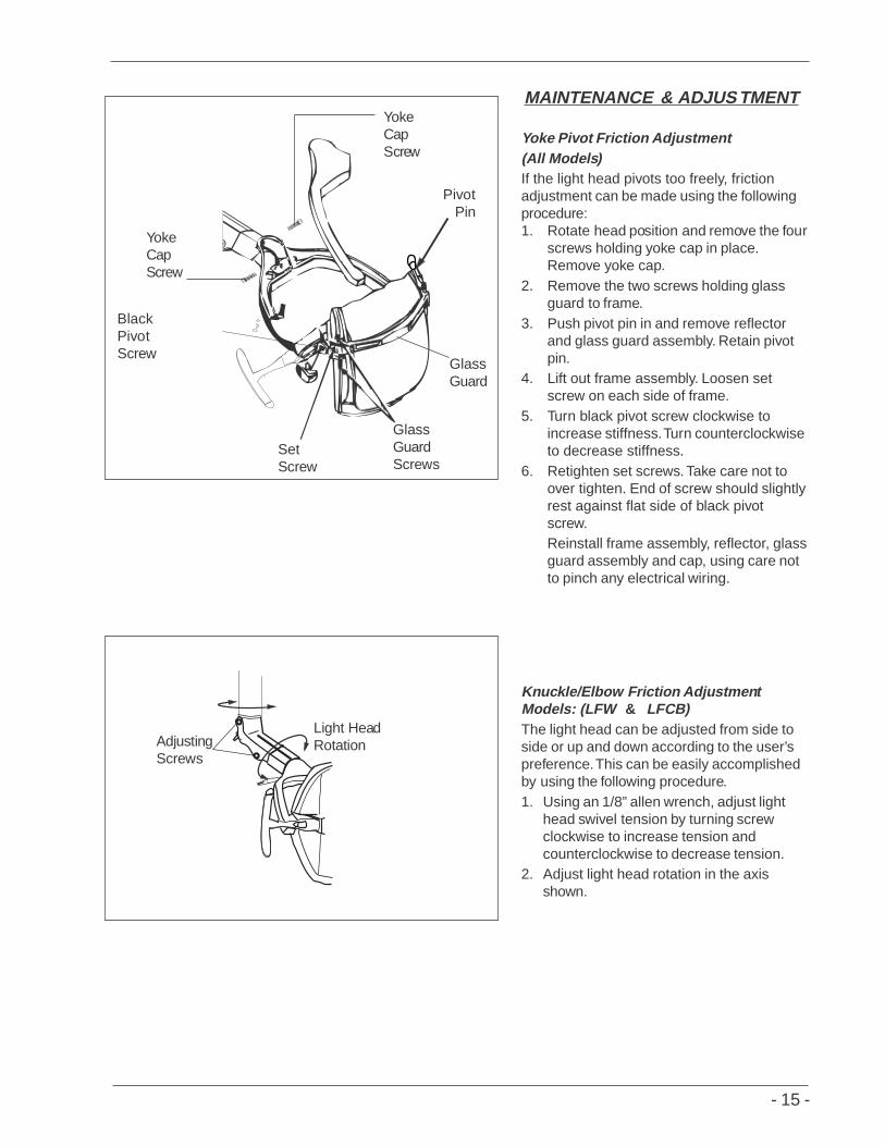
Yoke Pivot Friction Adjustment(All Models)If the light head pivots too freely, frictionadjustment can be made using the followingprocedure:1. Rotate head position and remove the four
screws holding yoke cap in place.Remove yoke cap.
2. Remove the two screws holding glassguard to frame.
3. Push pivot pin in and remove reflectorand glass guard assembly. Retain pivotpin.
4. Lift out frame assembly. Loosen setscrew on each side of frame.
5. Turn black pivot screw clockwise toincrease stiffness.Turn counterclockwiseto decrease stiffness.
6. Retighten set screws. Take care not toover tighten. End of screw should slightlyrest against flat side of black pivotscrew.Reinstall frame assembly, reflector, glassguard assembly and cap, using care notto pinch any electrical wiring.
Knuckle/Elbow Friction AdjustmentModels: (LFW & LFCB)The light head can be adjusted from side toside or up and down according to the user’spreference.This can be easily accomplishedby using the following procedure.1. Using an 1/8” allen wrench, adjust light
head swivel tension by turning screwclockwise to increase tension andcounterclockwise to decrease tension.
2. Adjust light head rotation in the axisshown.
Light HeadRotationAdjusting
Screws
YokeCapScrew
YokeCapScrew
GlassGuardScrews
PivotPin
GlassGuard
SetScrew
BlackPivotScrew

- 16 -
3rd-Axis Friction Adjustment(Models: LFC & LFT)The light head can be adjusted from sideto side or up and down according to theuser’s preference.This can be easilyaccomplished by using the followingprocedure.1. Using a 3/32" hex wrench, tighten the
elbow’s set screw securely.Turnelbow counterclockwise until itcompletely stops. Loosen the elbowset screw and turn elbow clockwise(A) until the front right corner of theelbow is aligned with the drop arm’sleft front corner (B). Tighten setscrew securely.
2. Using a 1/8" hex wrench, turn the 10/32 button screw on elbow assemblyclockwise to tighten tension on 3rdaxis rotation or counterclockwise toloosen tension.
Set Screw
Turnelbowclockwise
Alignelbowto arm
A
B
MAINTENANCE & ADJUS TMENT
Knuckle Joint Adjustment(Model: LFII & LFIII Unit Light)1. Loosen the two set screws.2. Rotate snubbing pins clockwise to
increase knuckle joint tension andcounterclockwise to decreasetension.
*NOTE: Flat side ofsnubbing pinsshould always be in line with setscrews after completing adjustment asshown.
3. Retighten set screws.Set Screws
1.
SnubbingPins
2.
*Flat Side ofSnubbing Pins

- 17 -
Single & Dual Track Lights- TrolleyAdjustments
If factory-adjusted side rollers become mis-aligned in shipping, adjustment will be necessarybefore installing the two side panels (A).
1. Loosen the two adjusting plate screws (B)on adjusting plates (C).
2. Position side rollers (D) against channel (E)and tighten adjusting screws.
3. Inspect freedom of trolley (F) movementand repeat necessary adjustments.
4. Loosen cord bracket screws (G) and centercord bracket (H) between dress covers (I).Tighten cord bracket screws.
Arm Joint Stiffness Adjustments-Ceiling Lights &Track Lights
5. Remove set screw (J).
6. Rotate arm counterclockwise (view up) todecrease joint stiffness or clockwise toincrease joint stiffness.
Reinstall set screw.
Adjustment of Column Stop Position -Ceiling Lights &Track Lights
NOTE: Column stop adjustmentmust beperformed before installation of roll pin (K).
Rotate arm clockwise (view up) until itstops.
7. To move stop position, remove two lockingset screws (L) and loosen collar by turningcounterclockwise until stop is in desiredposition.
Reinstall the two set screws.
WARNING: Set screws must betightened securely and roll pininstalled to prevent column fromunscrewing during operation.
Failure to install roll pin and tighten setscrews securely could result in lightfalling from ceiling.
MAINTENANCE AND ADJUS TMENT
A
1.B
1.C
2.D2.E 4.H
3.F4.I
1.C
2.D
1.C
4.G
4.H
1.B
K 7.L
6.5.J

- 18 -
Replacing Lamp (All Models)To replace the lamp, the following procedureshould be performed:
NOTE:For optimum performance and ex-tended lamp life, use only Pelton & Cranelamp (part no.017133) identified by Pelton &Crane on the ceramic ends.
WARNING:To avoid burningfingers or hand, ensure lamp is offand cool.
Open rear of light by depressing small pinon side of light frame. Rotate lamp 90° soedge can be held with fingers.
Hold lamp with left hand and press lever toright side with right hand. Remove lamp bygently pulling out.
CAUTION:Use tissue to hold newlamp while installing. Do nottouch new lamp with bare fingers.Contamination may shorten lamplife. If touched, clean with isopro-pyl alcohol and dry with cleancloth to remove fingerprints.
Install replacement lamp with exhaust tipaway from reflector.Close reflector.
Reflector Lamp
PARTS REPLACEMENT
Lever
ReflectorLamp
PlasticShield

- 19 -
NOTE

We reserve the right to make any alterations which may be due to technical improvements.
©2003, Pelton & CranePart No. 052109
Rev. 0, 6/06


![Pelton Turbines [Compatibility Mode]](https://img.pdfslide.us/doc/110x75/55cf92f8550346f57b9ab6bd/pelton-turbines-compatibility-mode.jpg)