Embed Size (px)
Citation preview

1

Light Belt Conveyor Installations – Engineering Guidelines
Edition: January 2008, replaces edition April 2003 2
Contents
1. Introduction...........................................................................................................5 2. Belt conveyor components................................................................................7
2.1 Figure showing system parts.........................................................................7 2.2 Variations on standard systems ....................................................................7
3. Supporting structure, pulley and roller fixing.........................................................9 3.1 Supporting structure ......................................................................................9 3.2 Fixing of pulleys and rollers ...........................................................................9
4. Belt support ........................................................................................................10 4.1 Slider bed ....................................................................................................10 4.2 Support by carrying rollers...........................................................................11 4.3 Belt support on the return side ....................................................................11
5. Drive station........................................................................................................12 5.1 Power transmission .....................................................................................12 5.2 Head drive ...................................................................................................12 5.3 Tail drive......................................................................................................13 5.4 Center drive.................................................................................................13 5.5 Tandem drive...............................................................................................13 5.6 Drive units ...................................................................................................13
6. Tensioning device...............................................................................................15 6.1 Fixed tensioning devices .............................................................................15 6.2 Constant-force tensioning device ................................................................15 6.3 Take-up xε ...................................................................................................16
7. Pulley diameter and width...................................................................................17 7.1 Minimum pulley diameter dmin....................................................................17
7.2 Smallest pulley diameter dy with respect to deflection ................................17
7.3 Smallest diameter of drive pulleys dAmin....................................................20
7.4 Pulley width .................................................................................................20 8. Driving pulley ......................................................................................................21
8.1 Smallest diameter dAmin.............................................................................21
8.2 Pulley shape................................................................................................22 8.3 Pulley surface..............................................................................................22 8.4 Friction cover ...............................................................................................23
9. Tail, deflection, snub and tension rollers.............................................................24 9.1 Roller diameter ............................................................................................24 9.2 Roller shape ................................................................................................24 9.3 Roller surface ..............................................................................................24 9.4 Snub roller ...................................................................................................24 9.5 Tension roller...............................................................................................25
10. Belt tracking in general....................................................................................26 10.1 Basic belt tracking measure ........................................................................26 10.2 Additional belt tracking measures................................................................27
11. Cylindrical-conical pulleys ...............................................................................28 11.1 Cylindrical-conical form ...............................................................................28 11.2 Crowned form..............................................................................................29

Light Belt Conveyor Installations – Engineering Guidelines
Edition: January 2008, replaces edition April 2003 3
11.3 Cylindrical-conical pulleys as a belt tracking measure.................................29 12. Guide/control rollers ........................................................................................30 13. Pivotable carrying rollers.................................................................................31 14. Inclined rollers on the return side ....................................................................32 15. Guiding profiles ...............................................................................................33
15.1 Guiding profiles as a general belt tracking measure....................................33 15.2 Guiding profiles for absorbing transverse forces .........................................33
16. Automatic belt control......................................................................................35 17. Further belt tracking measures .......................................................................36
17.1 Drive pulleys with a deformable tracking profile ..........................................36 17.2 Rollers with spiral-shaped grooves..............................................................36 17.3 Additional belt wrap .....................................................................................36 17.4 Carrying rollers with adhesive cover............................................................36 17.5 Pivoted rollers on the carrying side..............................................................37 17.6 V-shaped grooves in the slider bed .............................................................37 17.7 Belt scanning combined with pivotable carrying roller .................................37 17.8 Lateral guide rollers .....................................................................................37
18. Guiding of short, wide belts.............................................................................38 18.1 Inclined rollers on the return side.................................................................38 18.2 Guide/control rollers ....................................................................................38 18.3 Guiding profiles............................................................................................38 18.4 Alternatives..................................................................................................38
19. Feeding, accumulation, diverters of goods......................................................40 19.1 Feeding of conveyor with goods to be carried .............................................40 19.2 Accumulation of carried goods ....................................................................40 19.3 Diverting of conveyed goods ......................................................................40
20. Belt cleaning systems .....................................................................................42 21. Steep angle conveying....................................................................................43
21.1 Steep angle conveyor installation................................................................43 21.2 Z-conveyor installations...............................................................................44
22. Knife-edge belt conveyor ................................................................................46 22.1 Fixed knife edges ........................................................................................46 22.2 Rolling edges...............................................................................................47
23. Power turn installations (curved conveyors)....................................................48 23.1 Guidance by pairs of roller...........................................................................48 23.2 Guidance by means of profiles at the belt edge ..........................................48 23.3 Guidance by means of traveling drive chain................................................49 23.4 Execution of the tail rollers ..........................................................................49 23.5 Belt drive by frictional wheel ........................................................................49 23.6 Conveyor belt selection ...............................................................................50 23.6 Belt fabrication.............................................................................................50
24. 45°/30° belt merges (transfer conveyors)..........................................................51 25. Parallel running narrow belts...........................................................................53
25.1 Execution of the rollers ................................................................................53 25.2 Arrangement of the rollers, belt guidance....................................................54 25.3 Belt drive and take-up..................................................................................55
26. Troughed conveyors .......................................................................................56 27. Live roller conveyors .......................................................................................58

Light Belt Conveyor Installations – Engineering Guidelines
Edition: January 2008, replaces edition April 2003 4
27.1 Continuous conveying operations................................................................58 27.2 Accumulation operations .............................................................................58
28. Belt installation................................................................................................60 28.1 Checking the installation..............................................................................60 28.2 Belt assembly ..............................................................................................60 28.3 Belt alignment..............................................................................................62
29. Maintenance and cleaning ..............................................................................63 29.1 Maintenance................................................................................................63 29.2 Cleaning ......................................................................................................63
30. Storage ...........................................................................................................66 30.1 Storage conditions.......................................................................................66 30.2 Storage........................................................................................................66 30.3 Handling of heavy rolls ................................................................................66
Index..........................................................................................................................67

Light Belt Conveyor Installations – Engineering Guidelines
Edition: January 2008, replaces edition April 2003 5
1. Introduction
The objective of this Engineering Guideline is to provide both manufacturer and operator with a comprehensive, albeit summarized overview of the most important aspects of the installation and design of conveyor systems as it pertains to light conveyor belting. Although emphasis has been placed on belt tracking measures, recommendations on installation procedures, maintenance and cleaning, as well as actual storage of the conveyor belt itself have also been included. Light belt conveyor installations
The term “light belt conveyor” describes the conveyor belt systems used to convey all kinds of semi-finished and finished industrial products. They are used extensively in the handling of piece goods both in the food and non-food sectors and in general material handling for storage and distribution. Although light belt conveyor systems operate across a wide range of industries and industrial applications, some 50% of all systems currently in use are found in large distribution centers and in service operations such as postal facilities and airports. Another sector heavily dependent upon the use of these systems is the food industry, in both production and packaging centers.
Processing belts Processing belts are conveyor belts that not only perform purely conveying functions, i.e. transporting a product from point A to point B, but also have to perform important functions in the actual work process. Typical examples of processing belts would be the printing blanket on textile printing machines, crosslapper belts in non-woven fabric production (see picture), forming line and prepress belts in particle board production, belts for molders and cooling tunnels in large bakeries, treadmill belts, etc., etc. For all these applications, even the most demanding, the same principles apply with respect to equipment design and belt control as with conventional conveyor belt systems. Piece and bulk goods Although light belt conveyors are used primarily to convey small to medium sized piece goods, they can also be used for conveying bulk materials. The term “bulk material” is most commonly used when referring to materials such as soil, stone, building rubble and are moved by traditional conveyor belt systems equipped with thick, heavy duty, reinforced rubber belts. As far as light belt conveyor engineering is concerned, bulk materials are most generally categorized as granular, such as corn, rice, sugar, or even powder. European standard EN 873 Light conveyor belts are defined by European standard EN 873 with tensile strength being one technical feature that clearly distinguishes these belts from traditional heavy duty conveyor belts. With the light conveyor belt, ultimate tensile strength values are between 100 N/mm
Light Belt Conveyor Installations – Engineering Guidelines
Edition: January 2008, replaces edition April 2003 6
(571 lbs./in) and 1000 N/mm (5710 lbs./in). Whilst maximum admissible operating load is only some 10% of this figure. Structure of the Engineering Guideline This Engineering Guideline has been divided into a number of distinct chapters - each providing easily found and readily understandable information on a particular subject. More detailed performance information and common themes are clearly marked with relevant cross referencing to other sections and chapters. Simple, uncluttered drawings have been included to provide the reader with a clearer understanding of what is being described. Accordingly, supporting frame, slider bed, carrying roller, shaft bearing, belt running direction details have only been included in these drawings where necessary or where they are the actual issue being dealt with. For the most part, formulae are excluded except in cases where the authors believe that inclusion is essential. For greater clarity, certain details have been deliberately exaggerated: an example here being the geometry of crowned pulleys. The design, installation and operational procedures and recommendations found detailed in this Engineering Guideline have been found to be successful as a general rule in practice and in practical terms. It should be noted, however, that specific applications, specialized processes, and goods that need to be transported in a particular manner may all be issues that will impact on the overall system, its design, installation and operation. Further information The choice of the correct conveyor belt is a precondition for effective system operation and is often determined by the mechanical and chemical requirements of both the actual processes involved and the materials being transported. Detailed information on belt characteristics and application suitability can be found in the relevant Habasit literature and at www.habasit.com Habasit, with 20 affiliated companies, and agencies in over 50 countries, is able to provide a broad range of application experience and technical expertise and general product support world wide. Please do not hesitate to contact us whenever, or wherever you need support.
Liability clause, application considerations The proper construction, selection and application of Habasit products, including the related area of plant product safety, is the responsibility of the machine / installation manufacturer. All indications are recommendations and believed to be reliable, but no representations, guarantees, or warranties of any kind are made as to their accuracy or suitability for particular applications. The recommendations provided herein are based the exchange of experiences with machine and installation manufacturers, on practical experiences of users as well as on laboratory work. New knowledge and experiences can lead to modifications and changes within a short time without prior notice. BECAUSE REALIZATION OF THE RECOMMENDATIONS MENTIONED HEREIN ARE OUTSIDE OF HABASIT’S AND ITS AFFILIATED COMPANIES CONTROL, WE CANNOT ASSUME ANY LIABILITY CONCERNING MALFUNCTION OF MACHINES AND INSTALLATONS. THIS ALSO APPLIES TO PROCESS RESULTS / OUTPUT / MANUFACTURING GOODS AS WELL AS TO POSSIBLE DEFECTS, DAMAGES, CONSEQUENTIAL DAMAGES, AND FURTHER-REACHING CONSEQUENCES. Copyright Habasit AG Subject to alterations

Light Belt Conveyor Installations – Engineering Guidelines
Edition: January 2008, replaces edition April 2003 7
2. Belt conveyor components
In its simplest form, a belt conveyor consists of a supporting structure with belt support (slider bed or carrying rollers), a driving pulley, normally the “head” pulley, an idler roller, usually the “tail” pulley, and a conveyor belt. More complicated systems will have additional components such as drive and tensioning stations, belt tracking elements, product diverters, accumulators, sensors, etc. 2.1 Figure showing system parts
1 driving pulley 6 deflection roller 2 tail roller 7 tension roller 3 slider bed 8 carrying roller (on the return side) 4 carrying roller 9 conveyor belt 5 snub roller 10 supporting structure (not shown)
Sign for driving pulley Sign for tension roller with tensioning direction
Belt running direction 2.2 Variations on standard systems
The following standard systems does show the ones most commonly found in use for light belt conveyors, although not comprehensive as there are many further possible variations. Head drive, tail roller as tension roller Head drive, tensioning device on the return side

Light Belt Conveyor Installations – Engineering Guidelines
Edition: January 2008, replaces edition April 2003 8
Head drive, force-constant tensioning device on
the return side Drive on the return side, tail roller as tension
roller Drive and tensioning device on the return side Center drive, suitable for reversing operation In the case of a head driven conveyor, the conveyor belt is said to be pulled on the carrying side. Similarly, the belt on a tail driven conveyor is pulled in the return side. The head drive is preferred to the tail drive because of the smaller forces imparted to the conveyor components i.e., pulleys and bearings (see chapter 5). If no additional information available the conveying system is assumed as horizontal. In cases of steep angle conveyors, the angle of incline/decline, as well as the characteristics of the goods to be transported will dictate whether the belt is fitted with profiles. Normally, these installations require the use of belts with an adhesive (high friction) cover. Please refer to chapter 21 for further information about steep angle conveyor installations.

Light Belt Conveyor Installations – Engineering Guidelines
Edition: January 2008, replaces edition April 2003 9
3. Supporting structure, pulley and roller fixing
3.1 Supporting structure
The supporting structure must be rigid. It must not distort or flex from the forces it is subjected to i.e., belt tension, weight of the conveyed goods, uneven floors, etc. Without a rigid structure it would be almost impossible to track the conveyor belt by conventional means and keep it from running off under varying operating conditions (no-load / partial load / full load). The conveyor belt must be able to wander slightly from side-to-side without interfering with any fixed components. For this to be possible, it is essential that the supporting structure have ample clearance from the belt edges. Additionally, it is advantageous to configure the conveyor so the belt is visible along its path, and so there is sufficient accessibility for effective cleaning. It is essential for the supporting structure to have an earth ground through which the antistatic belts can discharge electrostatic potential through the pulleys and rollers. Note: Standard plastic pulleys and rollers, synthetic bearings and lubricants, and plastic slider beds are all insulators and will magnify the electrostatic charge of the belt. In case low noise is of importance for a conveying equipment, its superstructure requires special attention. The slider bed needs to be designed in a sound absorbing way. A diffusion of sound conducted through solids must be avoided. Especially noise absorbent conveyor belts can merely support noise reduction but cannot replace special design measures. The supporting structure must be accurately aligned in all planes. Checking for squareness should preferably be done by measuring across the diagonals (see chapter 28). 3.2 Fixing of pulleys and rollers
Normally the driving pulley when installed will be fixed and so not adjustable and as with all other pulleys and rollers, it must be aligned at right angles to the belt running axis. Adjustable bearings are recommended for the tail, deflection and tension rollers which are heavily loaded by the belt tensile force. Slotted fixing elements (Figure 3.2) are suitable for less heavily loaded rollers, such as pivoted carrying rollers and rollers for belt tracking. As a general rule only as many pulleys and rollers should be installed as are necessary to carry and guide the belt. Each pulley and roller can be the cause of belt running problems and for the accumulation of dirt. This leads to increased maintenance and cleaning.

Light Belt Conveyor Installations – Engineering Guidelines
Edition: January 2008, replaces edition April 2003 10
4. Belt support
4.1 Slider bed
The advantages of a belt supported by means of a slider bed are primarily that the transported goods lays with greater stability on the belt, and it presents virtually no influence on belt tracking – a distinct benefit versus a similar design which employs carrying rollers. With the correctly selected belt (with appropriate running side fabric) and slider bed material it is possible to favorably influence the coefficient of friction, running noise and the belt service life.
Preferred slider bed materials are:
� Pickled steel sheet (chemically descaled steel sheet) � Stainless steel sheet (used especially in the food sector) � Hard plastics (duroplastics such as phenolic resin etc.), mostly as a covering on chipboard
or plywood � Laminated hardwood sheets (beech, oak) The friction between slider bed and belt is considerably influenced by material type and surface finish of the slider bed as well by humidity, dust, dirt, etc. Attention is to be paid to the following points:
� The edge of the support must be rounded and be
lower than the pulley surface (∆h = approx. 2 mm (0.08 in.))
� The heads of mechanical fasteners must be recessed below the sliding surface.
� The slider bed must be precisely aligned relative to the running direction of the belt and it must be level such that there is no tilt (this is particularly important with slider beds of sheet steel panels), otherwise the belt will tend to run off.
� Thoroughly clean the slider bed before being put into service. Where and when necessary, the slider bed, pulleys and conveyor belt are to be periodically cleaned as dirt deposits can be a significant cause of performance problems i.e., belt running problems, increased coefficient of friction, belt damage etc.
� Excessive moisture between slider bed and belt increases adhesion (suction effect), resulting in a higher energy requirement, potentially leading to the overloading of the belt and/or drive. Grooves in the slider bed can provide for effective drainage and remedy these problems in such cases. Where these grooves are oriented in a “V” or chevron pattern, a belt tracking effect can be obtained simultaneously.
� Although projecting strips or grids as a support help prevent dirt, they also increase belt wear and running noise. It is advisable to avoid their use when at all possible.

Light Belt Conveyor Installations – Engineering Guidelines
Edition: January 2008, replaces edition April 2003 11
4.2 Support by carrying rollers
With long conveying distances and high overall
loads, carrying rollers can be used instead of a slider bed. The roller bed reduces friction losses, peripheral force and drive power requirements.
Most commonly used are rollers made
fromprecision steel tubes and roller bearings. Rollers with a plastic sheathing can also be used as they are resistant to corrosion and certain chemicals. A nonconductive synthetic covering can produce higher static charges during operation, particularly when use in conjunction with plastic bearings! Carrying rollers, in virtually all cases, have a cylindrical profile. As the conveyor belt only travels tangentially along the surface of these rollers and does not wrap around them, these rollers may have a smaller diameter than that specified for the belt’s dmin (see chapter 7). The diameter
specified however, must resist excessive deflection when the conveyor belt is under operational load. Attention must be paid to the following points:
� The distance between the carrying rollers should be less than half the length of the transported unit loads lG, in order that the goods carried are always
on at least two rollers. � Carrying rollers must be accurately fitted at right angles to the belt running axis as skewed
carrying rollers are frequently the cause of belt tracking problems. It is sufficient if the roller can only be adjusted from one side i.e., by means of slots in the supporting structure (see chapter 3).
� Carrying rollers can be installed for the purpose of guiding belt running; in these cases the
pivot angle γ must be at least ± 5° (see also chapter 13). It is recommended, especially with installations with long conveyors, that some of the carrying rollers are adjustable.
4.3 Belt support on the return side
Return rollers are recommended to have a center distance of under 2 meters (6.6 ft.), this will prevent excessive belt sag due to the belts own weight. These carrying rollers on the return side must also be installed accurately at right angles to the belt running axis as again inaccurately aligned rollers will often cause belt tracking problems, particularly in cases where high friction or structured belt covers are used.
Light Belt Conveyor Installations – Engineering Guidelines
Edition: January 2008, replaces edition April 2003 12
5. Drive station
The function of the driving pulley is to transfer the driving force (peripheral force) from the pulley to the belt. In special cases the drive station can also act as a brake. With steep gradient conveying (incline or decline) the drive unit is used to prevent the belt from moving when at rest. 5.1 Power transmission
Power transmission capacity of frictional engaged drives is, in principle, dependent upon the following factors:
� Arc of contact β of the belt at the driving pulley
� Coefficient of friction µ between belt and driving pulley
� Pressure force; resulting from the initial tension ε and the modulus of elasticity of the belt. Commonly used measures for increasing this power transmission capacity:
� Use of a snub roller to increase the arc of contact β
� Use of an elastomer coated driving pulley for increasing the coefficient of friction µ � An increase in the tensioning force.
This option, however, results in additional shaft and bearing load. Additionally, the allowable elongation of the belt must not be exceeded; therefore, a stronger belt may often be required.
The coefficient of friction and effective power transmission is largely dependent on the cleanliness of the pulley surface. Oil, grease, moisture, rust, dirt, conveyed product build-up, etc. all reduce friction and increase the potential for slip. Consequently, the belt and the system as a whole can no longer function properly. Cleanliness is equally important for issues such as belt tracking and service life. Care must be taken to ensure that the belt and installation are kept as clean as possible � by implementation of appropriate design measures (see chapter 20) � through effective cleaning procedures (see chapter 29). 5.2 Head drive
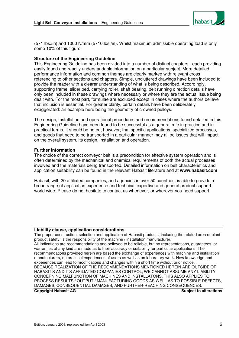
Conveying system stresses (belt forces, bearing and shaft loads, etc) are minimized in part by the optimizing the location of the drive. For this reason, the preferred location for the drive unit is at the “head”, or discharge, end of the conveyor.
One exception, however, is the declined conveyor where the magnitude of carried load, angle of decline, and friction make it possible for the conveyed product to drive, or push, the belt and create a “negative” peripheral force. It is in this case were the tail -drive is recommended for optimum performance.

Light Belt Conveyor Installations – Engineering Guidelines
Edition: January 2008, replaces edition April 2003 13
5.3 Tail drive
Greater belt tensile forces and higher shaft loads that occur in tail driven installations may, on occasion, demand stronger and more robust system construction. This issue becomes far more significant, however, in long installations, and where the mass of goods transported is great.
As mentioned above, the tail drive is preferable on the declined conveyor as the drive acts as a braking mechanism for the belt. 5.4 Center drive
Center drive is commonly specified for reversing operations. In this case, the rollers at each end of the conveyor may have cylindrical-conical shape (see chapter 11).
The center drive is also used for conveyors equipped on both the infeed and discharge ends with a nosebar, also called knife edge (see chapter 22). In such conveyor design, traction force is significantly increased as a result of these fixed components. Consequently, the increased power consumption and shaft loading must be considered. Belt guidance in conveyors with one or two nose bars and center drive is quite demanding. It is best to minimize total number of pulleys and rollers in the belt path. 5.5 Tandem drive
Tandem drives are used in situations demanding large drive power ratings and to increase the total arc of contact. This is seldom the case with light belt conveyor engineering as in most cases it is sufficient to increase the arc
of contact β by means of a snub roller and/or fit the driving pulley with a friction cover.
In processes where a high degree of positioning accuracy is required or the installation is long and/or where reversing operation is necessary, then both end rollers are typically driven. Where each of the tandem drive pulleys is driven by a dedicated motor, the drive system should incorporate a speed control system. The driving of one motor by another is to be avoided, as this can lead to the overloading of the belt. 5.6 Drive units
Generally the drive comprises motor, power transmission element (gearbox, belt) and driving pulley. Standardized three-phase squirrel-cage motors are preferable. The drive power ratings usually are relatively small (0.5 - 5 kW). The starting shock load is reduced by a commonly used star-delta start device.

Light Belt Conveyor Installations – Engineering Guidelines
Edition: January 2008, replaces edition April 2003 14
Converting motor speed to the required conveyor speed commonly takes place via a gearbox or a transmission belt and pulley combination. Often motor and gearbox are directly combined in a compact design (i.e., gear motor). Possible options are spur gear, bevel, or worm gears. If a power transmission belt is used, flat belt drives are recommended; these are space-saving, cost-effective, maintenance free and highly efficient. Speed control is increasingly being accomplished through electronically controlled drives, such as frequency inverter controlled squirrel-cage motors. Drum motors are also often used with relatively low power ratings. It’s important to note that drum motors are surface-cooled thereby partially dissipating its heat through the belt. It’s particularly noteworthy in short conveyors with a highly loaded drum motor, where it can result in severe, sometimes unacceptable overheating of the belt. Excessive and non-uniform heating of the belt is a frequent cause of belt running problems such as mistracking and belt shrinkage.

Light Belt Conveyor Installations – Engineering Guidelines
Edition: January 2008, replaces edition April 2003 15
6. Tensioning device
The required contact pressure of the conveyor belt on the driving pulley is achieved by means of a tensioning device. Usually, fixed tensioning devices are sufficient for light belt conveying installations. Habasit conveyor belts are dimensionally stable, with negligible elongation changes during startup or with load changes; therefore, no retensioning is required. As a general rule, the tensioning roller should be used exclusively to tension the belt. It is not advisable to skew the tensioning roller in order to track the belt because of the potential performance problems that an imbalance in tension may produced. 6.1 Fixed tensioning devices
Fixed tensioning devices are to be used in installations where there is no need to compensate for variations in belt length or belt tension during operation. � The simplest solution for tensioning is to use the
tail roller
with a tensioning device that runs parallel to the belt’s axis or the belt’s running direction.
� When the center distance between head and tail
rollers may not be changed, e.g. with intermediate, or transition conveyors, the tension station is incorporated in the return side.
� With long, heavy load installations, the tension
station should be positioned directly after the driving pulley and preferably be arranged horizontally.
� Tension rollers can be adjusted manually but may also be fitted with pneumatic or hydraulic
cylinders or even electric positioning motors to provide a fixed take-up position. 6.2 Constant-force tensioning device
In some cases, where the conveyor installation is lengthy, the transported weight is great (relative to the k1% of the belt) or rapidly fluctuating, then it is advisable to use constant-force
tensioning devices, that maintain the required belt tension under these conditions. This is also valid for belts with polyamide traction fabric (tensile member) and if there is considerable variation in humidity. With active, constant-force tensioning systems, belt length changes occurring during operation are compensated automatically. It is obvious, therefore, that these devices must be designed

Light Belt Conveyor Installations – Engineering Guidelines
Edition: January 2008, replaces edition April 2003 16
and built with the capability to compensate for these operational length changes as well as to take up the belt length for the required initial tension. Constant-forced belt tension is achieved either by weight (see illustration) or spring loaded pre-tensioning or by the installation of pneumatic or hydraulic tension stations. 6.3 Take-up xεεεε
For belts with polyester traction fabric the take-up should be at least 1.5% of the belt length. For belts with polyamide traction element, at least 2.5% take-up length should be included. Adequate consideration when determining the configuration and effective length of take-up must be given due to various factors: Required take-up for belt tensioning, influences due to fluctuations in temperature and moisture, potential for the build-up of debris on the conveyor components (increasing the length of the belt path), manufacturing tolerances of belt and installation, requirements to provide ease of installation and maintenance, etc.. Effective measures for keeping the take-up as short possible are: Head drive (instead of tail drive), driving pulley with friction cover, large arc of contact at the driving pulley, conveyor belt with a high modulus of elasticity (k1% value).

Light Belt Conveyor Installations – Engineering Guidelines
Edition: January 2008, replaces edition April 2003 17
7. Pulley diameter and width
As a general rule the larger the pulley diameter, the greater will be the durability of the conveyor belt system. However small diameters reduce the overall height, minimize transfer distance between adjacent conveyors, decreases installation weight and cuts cost. The following factors are used to determine the smallest possible diameter:
� Flexibility of the conveyor belt and that of any applied profiles (V-guides, cleats, etc.) See 7.1 Minimum pulley diameter dmin
� Admissible pulley deflection See 7.2 Smallest pulley diameter dy with reference to deflection
� The peripheral force to be transmitted by the drive pulley See 7.3 Smallest diameter of the driving pulley dAmin
7.1 Minimum pulley diameter dmin
Habasit defines a minimum pulley diameter dmin for each type of belt, applicable for an arc of
contact β greater than 30°. The minimum pulley diameter dmin is stated in the product data
sheets and is a key component toward designing for optimum performance; therefore, every effort should be made to be in compliance. The use of diameters smaller than those recommended can shorten belt life considerably.
In cases where the belt’s arc of contact with pulleys and rollers is minimal, then the diameter
specified can be smaller. For arc of contact β less than 30°, the admissible minimal diameter
can be about ½ dmin. For arc of contact β less than 5°, as in the case of carrying rollers, the
minimum pulley diameter dmin has not to be considered any more.
For belts with bonded profiles the minimum pulley diameter is a function of dmin of the belt,
profile size, shape, material and hardness, and type of bond. The minimum pulley diameter for belts with profiles is, therefore, determined by comparing the dmin of the belt to that listed for the
desired profile, and then abiding by the larger. 7.2 Smallest pulley diameter dy with respect to deflection
To support stable tracking behavior of the conveyor belt, the pulley deflection f caused by the belt tension must be minimized. The following values are recommended for the admissible deflection y:
� Cylindrical pulleys: y ≤ 0.001 · bo [mm]
� Cylindrical-conical pulleys y ≤ (0.001 · d) + 0.07 [mm] The following diagrams permit the quick determination of the smallest pulley diameter dy and
wall thickness w with respect to the admissible pulley deflection y of cylindrical-conical and cylindrical pulleys.

Light Belt Conveyor Installations – Engineering Guidelines
Edition: January 2008, replaces edition April 2003 18
Example 1: Determine the smallest pulley diameter dy of a cylindrical-conical, solid pulley with bo = 1000
mm, FW = 50,000 N
Enter into the upper diagram with data points bo = 1000 mm from the right column, and FW / bo
= 50,000 N / 1000 mm = 50 N/mm from the left column, and intersect at point A. Move vertically downward to intersection at point B with the line for solid pulleys. Move from B horizontally to the right column and obtain dy = 185 mm.
Example 2: As example 1, but with pulley wall thickness 10 mm Enter as for example 1. For the second entry: enter into the lower diagram with w = 10 mm and move to intersect at point C. Move horizontally to the right and obtain dy = 250 mm.

Light Belt Conveyor Installations – Engineering Guidelines
Edition: January 2008, replaces edition April 2003 19
Example 3: Determine the minimum wall thickness w of a cylindrical hollow pulley with dy = 200 mm, bo =
1000 mm, FW = 50,000 N
Enter in the upper diagram with bo = 1000 mm and FW / bo = 50,000 N / 1000 mm = 50 N/mm
and intersect at D. Enter the lower diagram at dy = 200 mm and move horizontally to the right
crossing the diagonal lines. Make a vertical reference line from intersection at point D to where it intersects the horizontal line created from dy = 200 mm at point E. Commencing from E, follow
the guide lines toward the right to obtain w = 5 mm. Example 4: Determine the smallest pulley diameter dy of a cylindrical solid pulley with bo = 1000 mm, FW =
50,000 N

Light Belt Conveyor Installations – Engineering Guidelines
Edition: January 2008, replaces edition April 2003 20
Enter as for example 3. The vertical reference line is taken from intersection point D to where it intersections the “solid pulley” reference line at point F. Move horizontally to the left to obtain dy = 135 mm.
Important: The effective pulley diameter deff must be at least as large as or larger than the
smallest diameters determined from sections 7.1 and 7.2:
deff ≥ dmin ≥ dy
7.3 Smallest diameter of drive pulleys dAmin
The principles described in 7.1 and 7.2 above also apply to the drive pulley. Additionally, forces occur at the periphery of the drive pulley which give rise to shear forces in the belt which must not exceed allowable levels. � Please refer to chapter 8 for assistance in determining the smallest diameter of drive pulleys. 7.4 Pulley width
Pulley and roller width is to be such that the belt
makes full contact with over its entire width, even when it is not positioned on the exact center of the pulley.
Pulley width recommendations:
Belt width bo Pulley width b
bo ≤ 100 mm (4 in.) b = bo + 20 mm (0.8 in.)
bo > 100 mm (4 in.) b = (1.08 � bo) + 12 mm (0.5 in.)

Light Belt Conveyor Installations – Engineering Guidelines
Edition: January 2008, replaces edition April 2003 21
8. Driving pulley
The principal function of the driving pulley is to transfer the peripheral force from the drive to the conveyor belt. If the driving pulley is cylindrical-conical it will also produce a tracking effect on the running behavior of the belt.
8.1 Smallest diameter dAmin
The same general principles as described in chapter 7, Sections 7.1 and 7.2 also apply when determining the size of the smallest diameter However, in the case of the driving pulley, consideration must also be given to the shear forces caused by the power transmission that occur at the periphery of the pulley. If the pulley diameter is too small the belt can be damaged. Special attention therefore needs to be paid to determining the correct size of the drive pulley. Unlike many other manufacturers, who do not take belt type into account when determining driving pulley diameter, Habasit has come up with an accurate and relatively simple-to-use formula that takes full account of the belt type in use:
Smallest diameter of the driving pulley [ ]mmk
k180cd
adm6minA ⋅
β⋅=
c6 = Calculation factor [-] see 1)
β = Arc of contact [°]
k = Effective tensile force per unit of width [N/mm], calculation see 2)
kadm = Admissible peripheral force per unit width [N/mm], product specific value
Explanations and calculation factors
1) Calculation factor c6
2) The effective tensile force per unit of width k is calculated from the peripheral force FU [N],
the coefficient of friction µ between pulley and belt, the arc of contact β)
[in radians] and the
belt width bo [mm], and is not to exceed kadm:
Tensile force per unit of width ( )
[ ]mm/Nkb
cF
e1b
Fk adm
o
4U
o
U <⋅
=−
=βµ−)

Light Belt Conveyor Installations – Engineering Guidelines
Edition: January 2008, replaces edition April 2003 22
Calculation factor c4
Calculation example
Required smallest diameter dAmin of a steel driving pulley, β = 180°, bo = 1000 mm, FWA =
50’000 N. The installed belt as an admissible nominal peripheral force kadm = 30 N/mm.
....... mm/N2510002
000'50
b2
Fk
o
WA ≈⋅
=⋅
≅
....... mm5,13730
25
180
180165
k
k180cd
zul6minA =⋅=⋅
β=
Important The effective diameter of the driving pulley dAeff must be at least as wide as, if not wider than
the largest diameter determined from section 7.1 (dmin), section 7.2 (dy) and section 8.1 (dAmin):
dAeff ≥ dmin ≥ dy ≥ dAmin
8.2 Pulley shape
Driving pulleys are usually cylindrical-conical in shape, they can on occasion also be convex. Both of these pulley profiles are capable of creating sufficient tracking force to guide correctly aligned conveyor belts. See chapter 11 for detailed information on cylindrical-conical pulleys. Additional belt tracking measures are recommended in cases where there are long conveyor belt installations that have high lateral forces which can occur from side feeding, diverter bars and from a large number of belt deflections. Cylindrical drive pulleys may be used in these cases when other belt tracking measures are employed. 8.3 Pulley surface
Clean, oil- and grease-free steel pulleys with a smooth, almost polished surface (corresponding
to a roughness Ra = 1,6 µm) are in most cases sufficient to ensure slip-free power transmission.
Driving pulleys with grooves or knurling are to be avoided as they may induce belt tracking problems and also will lead to excessive wear of the driven surface of the belt.

Light Belt Conveyor Installations – Engineering Guidelines
Edition: January 2008, replaces edition April 2003 23
To improve traction between belt and drive pulley, increase the arc of contact or use a pulley with friction cover. 8.4 Friction cover
Driving pulleys covered with an abrasion-resistant elastomer, e.g. nitrile rubber (recommended hardness 60-80 Shore A) or urethane (recommended hardness 80-90 Shore A) increase the coefficient of friction and thus the transferable peripheral force. Such friction covers may be applied in the form of a tube, a sheet, dip coated or sprayed on. Most commonly strips glued on in spirals has proven as a successful alternative to commercially available rubber-covered pulleys. Habasit offers two special friction cover materials (VT-270 und XVP-1320), but also normal belt material (e.g. HAT-8P or HAR-12E) can be used. With cylindrical pulleys, it should be noted that the peripheral speed at the cylindrical part of the pulley is higher than the speed at the conical side parts, so the belt is subject to differing shear forces. This effect will be intensified by the friction cover and may result in the degradation of the splice and to premature belt wear. We recommend therefore, that pulleys with friction covers are cylindrical and that belt tracking is guaranteed by other measures (chapters 12 to 18).

Light Belt Conveyor Installations – Engineering Guidelines
Edition: January 2008, replaces edition April 2003 24
9. Tail, deflection, snub and tension rollers
The roller at the end of the conveyor belt where the belt running-direction is reversed, is called the tail roller. Other rollers used for directional changing are known as deflection rollers. Snub rollers are simply a special type of deflection roller. The technical and engineering specification of these rollers is not as high as with a drive pulley as no power transmission takes place at these rollers. 9.1 Roller diameter
The diameter of tail, deflection, snub and tension rollers must be at least as wide as the minimum diameter dmin specified for a given conveyor belt. Furthermore, deflection is to be
maintained within certain limits both for reasons of physical strength and for the straight and true running of the conveyor belt. For minimum pulley and roller diameters dmin and dy please refer to chapter 7.
9.2 Roller shape
Tail, deflection, snub and tension rollers are normally cylindrical. With long conveyors the tracking effect of only one cylindrical-conical pulley, normally the driving pulley, is frequently not sufficient to guide the belt effectively over its entire length. In these cases it is advantageous to give the tail roller a cylindrical-conical profile. This issue becomes critical for conveying lengths of around 4-5 m (13 to 16 ft.) and upwards. For reversing operations, both tail rollers should be cylindrical-conical If no other measures are taken for belt tracking. Rollers and pulleys that run against the coated conveying side of the belt should always have a cylindrical profile. 9.3 Roller surface
Fewer demands are made on the surface finish of rollers than on driving pulleys. The tensile forces before and after the roller are identical, so there is no elongation difference and no
movement at the roller. Recommended roughness Ra = 3.2 µm.
9.4 Snub roller
The snub roller is of particular importance. It is primarily used to
- increase the arc of contact β at the driving pulley (= improvement in power transmission, lower initial tension, lower shaft load), and also to
- reduce the distance between carrying side
and return side (= reduced overall height),

Light Belt Conveyor Installations – Engineering Guidelines
Edition: January 2008, replaces edition April 2003 25
In addition, adjustable snub rollers are particularly effective in improving belt tracking. This is why adjustable snub rollers are known as guide or control rollers (see chapter 12). The distance a should be at least twice the diameter of the drive pulley or tail roller. When using belts with a structured surface it is recommended to equip the snub rollers with noise damping lagging. 9.5 Tension roller
The purpose of the tension roller is to pre-tension the belt and maintain that tension. Frequently the tail roller also acts as a tension roller. This method is highly cost effective, but should only be used in short conveyor installations. As a general rule, it is not advisable to use the tension roller for tensioning and belt control purposes simultaneously. For more information about belt tensioning devices refer to chapter 6.

Light Belt Conveyor Installations – Engineering Guidelines
Edition: January 2008, replaces edition April 2003 26
10. Belt tracking in general
The conveyor belt is frequently blamed for belt tracking problems and in most cases this is unjustified. The cause is usually to be found in the installation itself and may be the result of faulty design, incorrect application of belt tracking measures or poorly adjusted pulleys and rollers. It is therefore essential to be fully aware of the basic characteristics of the different belt tracking measures and for these to be employed correctly. A distinction needs to be made between basic and additional measures for belt tracking. The former are appropriate for maintaining a correctly aligned belt in its central position as long as no great external influences are exerted on the belt, such as transverse forces. The latter are necessary when the basic measures alone are either insufficient or inappropriate to control belt tracking properly. Regardless which measures are taken, the following conditions are essential for problem-free belt tracking: � The supporting structure must be stable. It must be able to withstand all the forces acting
upon it (belt tension, weight of the conveyed goods, uneven floors etc.) � All pulleys and rollers must be fitted at right angles to the belt-running axis. Adjustable
pulleys and rollers are only to be reset after the belt has been properly run in. � All parts of the installation that come into contact with the belt are to be protected from dirt
and soiling and are to be cleaned as and when necessary. 10.1 Basic belt tracking measure
Where a belt runs over two cylindrical pulleys that are at right angles to its directional path then the forces acting upon it will be parallel to the direction of the belt. No tracking forces are exerted on the belt. In fact, the belt is running in a state of unstable equilibrium and would run off immediately if subjected to the slightest external factors, such as dirt, changes to the installation geometry, and belt distortion. The same scenario applies, should one of the two pulleys, not be positioned accurately at right angles to the belt running axis. The belt will inevitably run off towards the less tensioned side. It is therefore desirable to utilize cylindrical-conical pulleys and rollers as a basic measure to achieve straight and stable running. These pulleys and rollers exert a self-tracking effect, that is to say, where there is a variable run-off tendency, or a reversal in running direction, the belt is centered without the need to adjust the axis. Detailed information on cylindrical-conical pulleys and rollers is contained in chapter 11.

Light Belt Conveyor Installations – Engineering Guidelines
Edition: January 2008, replaces edition April 2003 27
The cylindrical-conical form is usually selected for at least one pulley and in most cases this will be the driving pulley. The driving pulley is then installed fixed while the tail roller is adjustably installed in order to be able to set belt running. Following this method, a correctly aligned belt can be maintained in its central position as long as there are no great deflection forces.
With conveying lengths in excess of 4-5 meters (13 to 16 ft.) and in installations with reversing operations, it is advisable to use a cylindrical-conical shape for both drive pulley and tail roller. 10.2 Additional belt tracking measures
On installations with a pronounced run-off tendency and considerable transverse forces (side feed, diverter bar, a large number of belt deflections etc.), the basic measure described above, indicating the use of cylindrical-conical pulleys, will not be sufficient. Additional belt tracking measures will be required, but these will be determined by application and operating conditions. Please refer to the following chapters for further detail: � Guide/control rollers (chapter 12) � Pivotable carrying rollers (chapter 13) � Pivotable rollers in the return side (chapter 14) � Guiding profiles (chapter 15) � Automatic belt control (chapter 16) � Further tracking measures (chapter 17)

Light Belt Conveyor Installations – Engineering Guidelines
Edition: January 2008, replaces edition April 2003 28
11. Cylindrical-conical pulleys
For tracking of conveyor belts cylindrical-conical formed (trapezoidal crowned) or simple crowned pulleys are effective for use. As the belt tries to run to the highest point of a pulley, which is oriented at right-angles to the belt run, it is constantly pulled towards the center of the pulley by the conical ends.
Pulleys with this shape exert a self-centering effect to the belt, so that, even with changing run-off tendencies during operation or with reversal running direction, the belt will be tracked optimally without the need to adjust the axis. In order to achieve an optimum belt tracking and this without experiencing any negative impact on belt operation behavior or belt service life, the pulley shape, that is the ratio of the conical parts to the cylindrical part and the conicity, should be done according our recommendations. 11.1 Cylindrical-conical form
Length of the cylindrical part bc :
bo ≤ 2000 mm (80 in.): 2
bb
oc =
bo > 2000 mm (80 in.): bc = bo – 1000 mm (40 in.)
Gradient h of the conical part Gradient h = 2 · ( 0.001 · d + 0.075 ) [mm]
Diameter d [mm] (in.)
≤ 50
≤ 2
100 4
150 6
200 8
250 10
300 12
350 14
400 16
450 18
500 20
>500 >20
Gradient h [mm] (in.)
0.25 .010
0.35 .014
0.45 .018
0.55 .022
0.65 .026
0.75 .030
0.85 .034
0.95 .038
1.05 .042
1.15 .046
1.5 .060
Attention should also be paid to the following points: � An exaggerated slope may result in longitudinal
creasing and, in extreme cases, lead to belt overlapping.
For thin, laterally flexible belts (e.g. FAB-3EB, ENI-5AQ etc.), it is advisable to reduce the
value of h to about 50% of the above listed values. � On belts with high transverse rigidity an
excessively high slope will result in the loss of the tracking effect because the belt does not run close enough to the conical side parts.
� In the case of exaggerated slope, the belt is subjected to varying tension which has a
negative impact on belt life.
Light Belt Conveyor Installations – Engineering Guidelines
Edition: January 2008, replaces edition April 2003 29
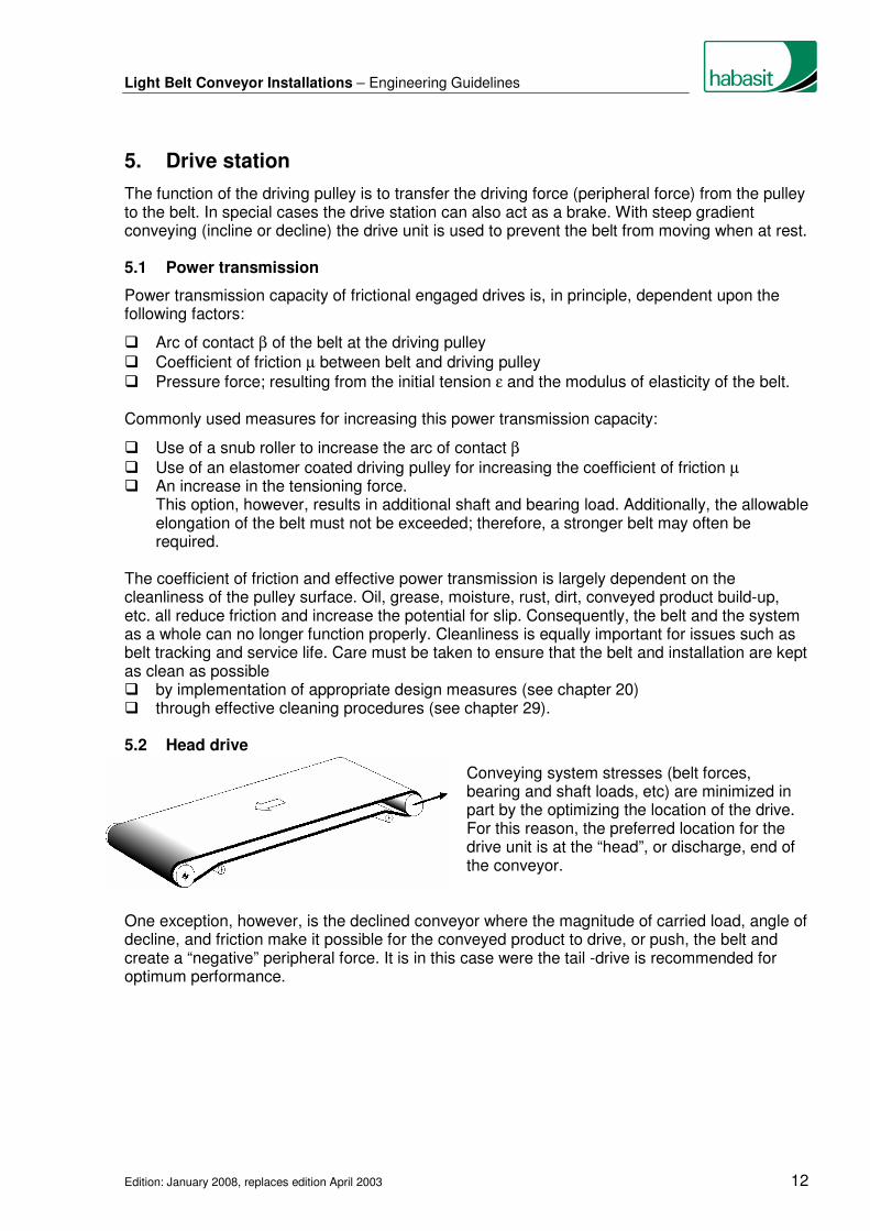
� The belt must not be wider than the pulley width, otherwise the self-centering effect of the conical
side parts will be completely lifted. 11.2 Crowned form
The value of gradient h is recommended also for the height of the crown. In general the cylindrical-conical profile is preferred to that of the crowned profile for technical production reasons. 11.3 Cylindrical-conical pulleys as a belt tracking measure
It is usual but not obligatory for driving pulleys to be cylindrical-conical in profile. These pulleys/rollers in themselves represent effective tracking measures for correctly aligned conveyor belts. However, on long installations and where great lateral forces are present, as can be the case with side feed, diverter bars and large numbers of belt deflections, additional belt tracking measures are needed (see chapters 12 to 17).

Light Belt Conveyor Installations – Engineering Guidelines
Edition: January 2008, replaces edition April 2003 30
12. Guide/control rollers
Due to their outstanding tracking effect on the belt, pivotable snub rollers are termed guide rollers or control rollers. The tracking effect is optimized when the guide/control roller is fitted on the running-on side in front of the tail roller with head drive and in front of the driving pulley in the case of tail drive.
It should be noted that guide/control rollers are
cylindrical and that their diameter should be at least 2/3 that of the diameter of the drive pulley or tail roller. Please refer to chapter 7 for further requirements.
To achieve good tracking, the arc of contact at the guide/control roller must be at least 30°. On belts without coverings the tracking effect can be improved with a friction covering of abrasion-resistant rubber or a synthetic material (preferably polyurethane, 80-90 Shore A). To keep the belt tensions in the peripheral area as low as possible, the pivoting movement should, wherever possible, be perpendicular to the median line of the arc of contact (plane
A ↔ B). As with the snub roller, other pivotable cylindrical rollers can be fitted and used as belt tracking measures (deflection and tension rollers etc.), However, the tracking effect produced by these rollers will not be as great as with the snub roller, as their effectiveness is dependant on location and the arc of contact. Unlike cylindrical-conical pulleys, pivotable cylindrical rollers are not automatically self-tracking. This means when the run-off tendency or the running direction changes, the pivoted position must be reset. As this is not practicable, the use of pivotable cylindrical rollers for belt tracking is, in general, not to be recommended. Guide/control rollers remain an exception to this rule. Provided there is sufficient distance between
drive pulley and tail roller, guide/control rollers can be used, even for reversing operations.
(Figure 12.2) Guide/control roller A acts with tail drive Guide/control roller B acts with head drive
Light Belt Conveyor Installations – Engineering Guidelines
Edition: January 2008, replaces edition April 2003 31
13. Pivotable carrying rollers
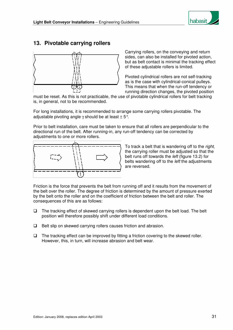
Carrying rollers, on the conveying and return sides, can also be installed for pivoted action, but as belt contact is minimal the tracking effect of these adjustable rollers is limited.
Pivoted cylindrical rollers are not self-tracking as is the case with cylindrical-conical pulleys. This means that when the run-off tendency or running direction changes, the pivoted position must be reset. As this is not practicable, the use of pivotable cylindrical rollers for belt tracking is, in general, not to be recommended. For long installations, it is recommended to arrange some carrying rollers pivotable. The
adjustable pivoting angle γ should be at least ± 5°. Prior to belt installation, care must be taken to ensure that all rollers are perpendicular to the directional run of the belt. After running-in, any run-off tendency can be corrected by adjustments to one or more rollers. To track a belt that is wandering off to the right,
the carrying roller must be adjusted so that the belt runs off towards the left (figure 13.2) for belts wandering off to the left the adjustments are reversed.
Friction is the force that prevents the belt from running off and it results from the movement of the belt over the roller. The degree of friction is determined by the amount of pressure exerted by the belt onto the roller and on the coefficient of friction between the belt and roller. The consequences of this are as follows: � The tracking effect of skewed carrying rollers is dependent upon the belt load. The belt
position will therefore possibly shift under different load conditions. � Belt slip on skewed carrying rollers causes friction and abrasion. � The tracking effect can be improved by fitting a friction covering to the skewed roller.
However, this, in turn, will increase abrasion and belt wear.

Light Belt Conveyor Installations – Engineering Guidelines
Edition: January 2008, replaces edition April 2003 32
14. Inclined rollers on the return side
The tracking effect of inclined rollers in the return side is maximized if they are fitted to the running-on side in front of the tail roller for head drive and in front of the driving pulley for tail drive. The positioning of rollers under the belt, i.e. on
the conveying side of the belt produces a good tracking effect due to the high coefficient of friction, however, possible tracking marks on the belt covering must also be taken into consideration.
The rollers can also be positioned above the
belt on its running side. This is desirable in cases where the belt has a delicate or highly structured conveying side with transverse profiles.
To achieve a satisfactory tracking effect, the belt contact of a roller should be around 1/4 of the belt width and the roller inclination should be 5° to 10°. If the inclined rollers are fitted exactly at right angles to the belt running direction, the belt will automatically correct its own position should a change in run-off tendency occur. This measure works also in reversing operation. Belt tracking is further improved when the inclined rollers are angled forward by 8° to 10° at the belt edges in the running direction of the belt. However, rollers angled forward can not be recom- mended for reversing operation! Inclined rollers on the return side have also proved successful for tracking wide, short belts (see chapter 18) and with thin belts at high speeds. In this case drive pulleys and tail rollers are to be fitted with cylindrical profiles in order to avoid folding or creasing.

Light Belt Conveyor Installations – Engineering Guidelines
Edition: January 2008, replaces edition April 2003 33
15. Guiding profiles
Guiding profiles are usually V-shaped or are flat profiles welded onto the running side of the conveyor belt. They are employed for two fundamentally different reasons: - As a general belt tracking measure - As a measure to absorb transverse forces 15.1 Guiding profiles as a general belt tracking measure
Guiding profiles can only solve minor run-off tendencies. Minor run-off tendencies have to be expected in installations with a narrow belt width, low belt speed, low tensioning force and where no external transverse forces act upon the belt. Where these conditions are not given, guiding profiles are not recommended, as they have a tendency to pop out of the groove and then the belt continue to run off. Because of the relatively high production costs and their limited effectiveness, guiding profiles are not recommended as a general belt tracking measure. However an exception is the use of guiding profiles for belt tracking with short, wide belts (see chapter 18). 15.2 Guiding profiles for absorbing transverse forces
In this context the term transverse forces refers to those forces exerted briefly on the side of the conveyor belt. They occur, for instance, during side loading or unloading. In these cases, and in contrast to the situation outlined in 15.1 above, it is not a question of dealing with a continuous run-off tendency of the belt. Here the guiding profiles need to counter locally occurring transverse forces and so prevent the belt, which is guided by other measures, normally cylindrical-conical pulleys, from running off. Guiding profiles, both in the center of the belt and at the belt edges are well suited to this purpose. The following points are to be noted:
� The belt must have sufficient transverse rigidity to prevent it from being thrown out by the transverse force.
� To ensure that the rest of the belt run is not influenced by the run-off forces, the belt must
be guided at the point where the transverse forces occur. The groove dimensions are therefore to be differently sized: In the zone where the transverse force
occurs, that is to say in the slider bed or in the carrying rollers in question, the grooves should be narrow, i.e. around 4 mm (0.16 in.) wider than the guiding profile.

Light Belt Conveyor Installations – Engineering Guidelines
Edition: January 2008, replaces edition April 2003 34
At the other locations and especially at the drive pulley and tail roller the grooves should be around 10 mm (0.39 in.) wider than the guiding profile. The greater clearance permits the adjustment of the belt without the guiding profiles permanently running against the sides of the grooves.
� In case guiding profiles are attached outside the center and close to the belt edge, tapered
pulleys are losing their guiding effect. In such cases cylindrical pulleys are recommended. � With wider (> 400 mm (16 in.)) and faster running
(> 0.5 m (1.6 ft.)/s) belts, the use of idler rollers is recommended to prevent the profile from climbing out of the grooves.
� All grooves must be accurately aligned. � The edges of the grooves are to have a 2 to 4 mm (0.08 to 0.16 in.) chamfer to prevent
damage to the guiding profiles. � Great care is necessary when running-in. Belt tracking must be effected by use of the
correct and appropriate measures e.g. cylindrical-conical pulleys. The guiding profile must run without the application of force in the grooves.
� The required minimum pulley diameter for the guiding profile is to be specified and fitted. � Generally a single guiding profile in the center of the belt is sufficient. V-profiles are well
suited to this application. � For thin belts with low transverse rigidity and also for wide belts, two guiding profiles should
be used and positioned as near to the belt edges as possible. Both V-profiles and flat profiles can be used in these cases.
� Flat profiles at the belt edges provide extra
protection for pulleys, rollers and slider bed against dirt, but should only be used on cylindrical pulleys.
Light Belt Conveyor Installations – Engineering Guidelines
Edition: January 2008, replaces edition April 2003 35
16. Automatic belt control
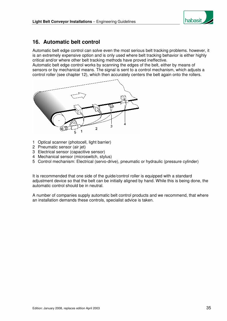
Automatic belt edge control can solve even the most serious belt tracking problems. however, it is an extremely expensive option and is only used where belt tracking behavior is either highly critical and/or where other belt tracking methods have proved ineffective. Automatic belt edge control works by scanning the edges of the belt, either by means of sensors or by mechanical means. The signal is sent to a control mechanism, which adjusts a control roller (see chapter 12), which then accurately centers the belt again onto the rollers. 1 Optical scanner (photocell, light barrier) 2 Pneumatic sensor (air jet) 3 Electrical sensor (capacitive sensor) 4 Mechanical sensor (microswitch, stylus) 5 Control mechanism: Electrical (servo-drive), pneumatic or hydraulic (pressure cylinder) It is recommended that one side of the guide/control roller is equipped with a standard adjustment device so that the belt can be initially aligned by hand. While this is being done, the automatic control should be in neutral. A number of companies supply automatic belt control products and we recommend, that where an installation demands these controls, specialist advice is taken.
Light Belt Conveyor Installations – Engineering Guidelines
Edition: January 2008, replaces edition April 2003 36
17. Further belt tracking measures
In addition to the belt tracking measures already described in chapters 11 to 16, there are other options that can be used depending on certain preconditions and on type of application. The relative advantages and disadvantages of a number of these are set out below. 17.1 Drive pulleys with a deformable tracking profile
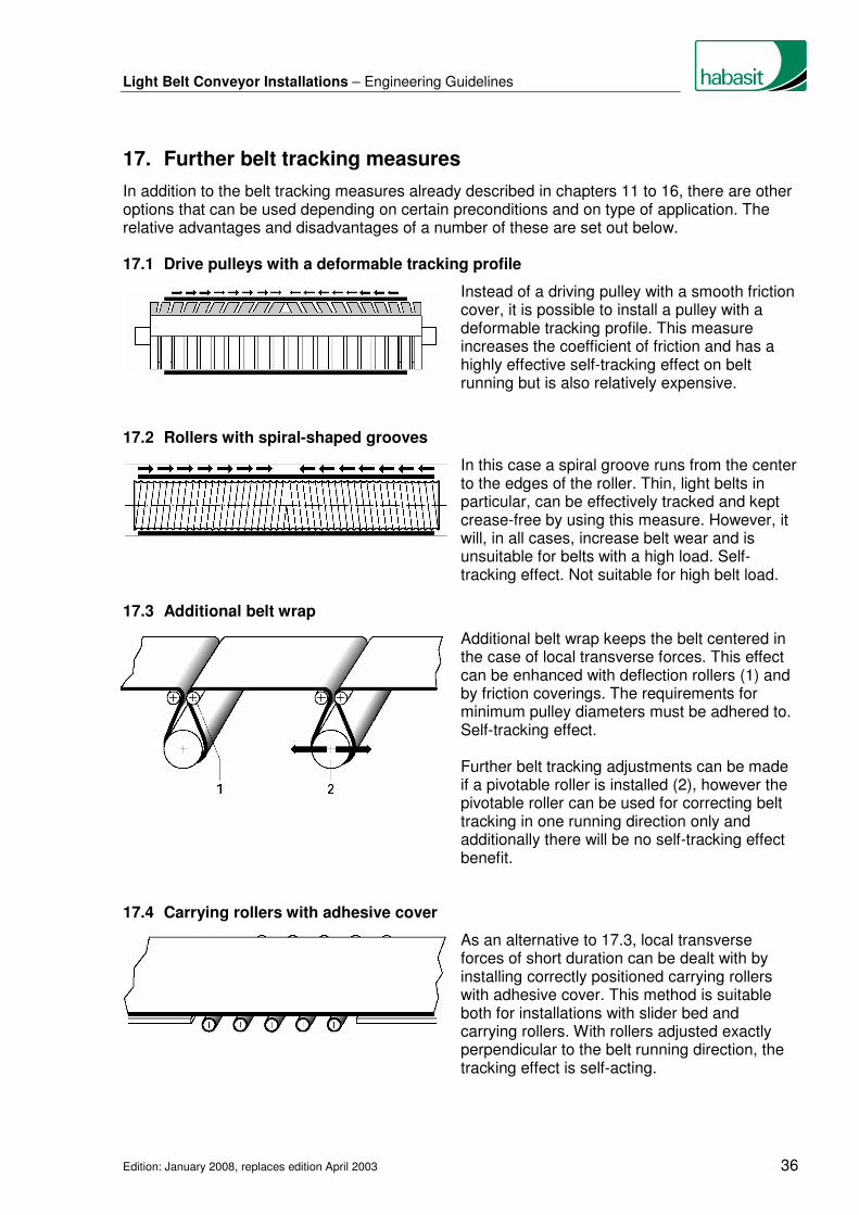
Instead of a driving pulley with a smooth friction cover, it is possible to install a pulley with a deformable tracking profile. This measure increases the coefficient of friction and has a highly effective self-tracking effect on belt running but is also relatively expensive.
17.2 Rollers with spiral-shaped grooves
In this case a spiral groove runs from the center to the edges of the roller. Thin, light belts in particular, can be effectively tracked and kept crease-free by using this measure. However, it will, in all cases, increase belt wear and is unsuitable for belts with a high load. Self-tracking effect. Not suitable for high belt load.
17.3 Additional belt wrap
Additional belt wrap keeps the belt centered in the case of local transverse forces. This effect can be enhanced with deflection rollers (1) and by friction coverings. The requirements for minimum pulley diameters must be adhered to. Self-tracking effect.
Further belt tracking adjustments can be made
if a pivotable roller is installed (2), however the pivotable roller can be used for correcting belt
tracking in one running direction only and additionally there will be no self-tracking effect benefit.
17.4 Carrying rollers with adhesive cover
As an alternative to 17.3, local transverse forces of short duration can be dealt with by installing correctly positioned carrying rollers with adhesive cover. This method is suitable both for installations with slider bed and carrying rollers. With rollers adjusted exactly perpendicular to the belt running direction, the tracking effect is self-acting.

Light Belt Conveyor Installations – Engineering Guidelines
Edition: January 2008, replaces edition April 2003 37
17.5 Pivoted rollers on the carrying side
Cylindrical rollers can be installed in the slider bed, these must be angled forward in the same direction as the belt running direction and fitted at the edges of the belt. The angle of slant should be between 3° and 12° and will depend upon belt load, on the friction coefficient between roller and belt and on the belt speed. Since the belt does not only run on the rollers but also slides, there appears friction and thus increased belt wear. This method centers the belt only in one running direction and cannot be used for reversing operations, nor can it be used with thin belts of low transverse rigidity as these will be thrown off center by the very considerable tracking forces present.
17.6 V-shaped grooves in the slider bed
Grooves in the slider bed are primarily there for the removal of moisture between belt and support. Where these grooves are V-shaped, they produce a relatively weak tracking effect on the belt. On taut belts and those with low loads, the effects are negligible but can be improved by fitting strips to the belt, however this increases belt wear as well as operating noise.
17.7 Belt scanning combined with pivotable carrying roller
This is only possible for heavy belts and for belts with high transverse stability. Specialist manufacturers supply these units, which can also be equipped with adjustable scanners that substantially reduce belt edge, wear.
17.8 Lateral guide rollers
In practice this measure is only possible for belts with sufficient transverse rigidity and edge strength, however, belt edge wear will increase. This measure can not be recommended from the point of view of belt life cycle. If lateral guidance cannot be avoided, guide rollers
are preferable to lateral wearstrips.

Light Belt Conveyor Installations – Engineering Guidelines
Edition: January 2008, replaces edition April 2003 38
18. Guiding of short, wide belts
Conveyor belt installations, where the width of the belt is greater than its conveying length, are difficult to guide. Namely thin belts with little lateral stiffness, particularly at high speed, on short conveying distances have a tendency to fold and overlap when fitted with cylindrical-conical rollers. Habasit recommends therefore that cylindrical pulleys should be fitted on short, wide installations. Other measures, however, will need to be used to guarantee effective belt guidance in these cases. The following can be recommended. 18.1 Inclined rollers on the return side
A solution recommended for guiding wide belts with short conveying distances (see chapter 14). The measure is also effective with reversing operations where the rollers fitted are at right angles to the belt running direction.
18.2 Guide/control rollers
Pivotable guide/control rollers achieve good
tracking results. However, they are not self-tracking and so cannot be used with reversing operations (see chapter 12).
18.3 Guiding profiles
Short, wide belts can be guided relatively effectively by using guiding profiles, but only where there is sufficient transverse rigidity and at fairly low speeds. It is recommended that two profiles be fitted at the belt edges, so that they act as simultaneous belt stiffeners. With short wide belts, pulleys can be used to guide the profiles. In these cases the grooves in the pulleys are narrower than those in the slider bed. For more detail please refer to chapter 15. 18.4 Alternatives
In cases where the application does not absolutely ask for a wide belt, the use of several narrow belts is recommended.

Light Belt Conveyor Installations – Engineering Guidelines
Edition: January 2008, replaces edition April 2003 39
The tracking can be controlled much easier. A disadvantage is that each belt must have a tensioning device, unless elastic belts are used. Further references see chapter 25. Another recommended alternative is the use of modular belt technology (HabasitLINK®). As the drive for this type of system is effected over cogged (or toothed) wheels belts are guided in an ultimate way. For the design of modular belt conveyors special requirements must be taken into account. Please call your nearest Habasit outlet for details.

Light Belt Conveyor Installations – Engineering Guidelines
Edition: January 2008, replaces edition April 2003 40
19. Feeding, accumulation, diverters of goods
19.1 Feeding of conveyor with goods to be carried
Conveyor belts are mechanically stressed during the loading of goods, both from the impact of actual loading as well as the additional movement between the goods themselves and the belt. Effective loading of goods onto conveyors can require a number of fixtures, such as side plates, chutes and funnels to be fitted to the overall installation. Loading should preferably take place
� with low energy impact,
� in the same direction as the belt is running,
� at belt speed (vB) and
� with goods positioned centrally on the belt. These ideal conditions are not always possible and in the case of lateral feeding the belt is subject to unavoidable high stress. Accordingly, belts with high abrasion resistance and transverse rigidity must be fitted. It is essential that the belt remains centrally positioned on the conveying installation at the point of loading. The following measures deliver good solutions:
� Additional belt wrap (see 17.3)
� Carrying rollers with adhesive covers (see 17.4)
� Guiding profiles (see 15.2) 19.2 Accumulation of carried goods
The term accumulation describes the situation that arises when either the whole or part of the belt becomes congested with goods while the belt continues to run. Special attention should be given to the following points when specifying belts in these cases:
� Install a conveyor belt with a low friction, wear-resistant surface.
� Take into account the increase in the peripheral force resulting from the dynamic friction generated by the accumulated goods on the continuously advancing belt.
� Where large amounts of goods have to be accumulated, a live roller conveyor (chapter 26) or a modular belt is probably more effective than a belt conveyor.
19.3 Diverting of conveyed goods
Where piece goods are diverted or retrieved from the side, care is to be taken to keep transverse forces on the belt as low as possible. Diverters must not touch the belt.
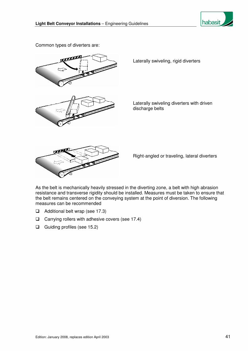
Light Belt Conveyor Installations – Engineering Guidelines
Edition: January 2008, replaces edition April 2003 41
Common types of diverters are: Laterally swiveling, rigid diverters Laterally swiveling diverters with driven
discharge belts Right-angled or traveling, lateral diverters As the belt is mechanically heavily stressed in the diverting zone, a belt with high abrasion resistance and transverse rigidity should be installed. Measures must be taken to ensure that the belt remains centered on the conveying system at the point of diversion. The following measures can be recommended
� Additional belt wrap (see 17.3)
� Carrying rollers with adhesive covers (see 17.4)
� Guiding profiles (see 15.2)

Light Belt Conveyor Installations – Engineering Guidelines
Edition: January 2008, replaces edition April 2003 42
20. Belt cleaning systems
Soiled belts and system components cause belt tracking and drive problems and shorten belt life. Dirty belt surfaces impair the belt’s carrying ability and release properties that lead to conveying and processing problems. From a hygiene standpoint dirty belts are, of course, totally unacceptable for food industry processes, but they are also undesirable, for environmental and aesthetic reasons. To maintain continuous cleanliness, various measures are available such as mounted scrapers and brushes. Scrapers are bars of synthetic material or rubber fitted across the belt’s running direction. The scraper material should be less durable than that of the belt and should be adjustable, being as it is, subject to wear. Scrapers (1) should be mounted very close to the belt, in fact may lightly touch it. Fixed scrapers with brushes (2) will help to protect the coating on the conveying side. Brushes that rotate against the belt running direction (3) are well suited to cleaning applications where the waste material is sticky or dusty, especially for textured surfaces. It is also possible to attach water spray devices if this is deemed necessary. Scrapers and brushes must of course be continuously and thoroughly cleaned. To prevent the accumulation of dirt and other material between pulleys and belt, scrapers should be fitted on the running side and as close as possible to the tail roller. Plough type scrapers (4) do not affect belt running behavior as is the case with adjustable/slanted scrapers (5). Attention must be paid to ensure that cleaning systems are properly and correctly installed as otherwise belt tracking problems may occur. Another point that must be considered is the increase in peripheral force due friction. For belt maintenance and cleaning see chapter 29.

Light Belt Conveyor Installations – Engineering Guidelines
Edition: January 2008, replaces edition April 2003 43
21. Steep angle conveying
The same principles of construction and belt guidance apply to the conveyance on inclined sections as discussed in the previous chapters. The following points should also be taken into account. 21.1 Steep angle conveyor installation
Head drive is recommended for upward conveyance, while tail drive is preferable for downward installations as it acts as a brake when required. This finally means, in both cases it is best to install the drive station at the top of the conveyor. The maximum gradient on which goods can be conveyed without slipping or tilting depends on the following factors: � Weight, surface finish (material, structure) and position of the center of gravity of the
conveyed goods
� Surface finish (material, structure) of the conveyor belt
� Operation conditions (belt speed, stop-and-go, vibrations)
� External influences (humidity, temperature, soiling) The choice of the correct conveyor belt is very important. As a general rule, belts with a smooth
but adhesive surface can be used for installations with gradients of about δ ≤ 20°.
Belts with a structured conveying side can be used for gradients of up to δ ≅ 40° to 45°. From
about δ > 45° transverse profiles are required. Extreme gradients are often managed by spiral conveyors.
The maximum possible angle of inclination δ for the conveyance of product X with belt Y can be determined by a simple method. Fix a sample belt (1) on a fixed support, such as a wooden board (2) and place on it one or more of the goods to be conveyed (3). Now incline the support until the goods start to slide. Measure the gradient height hT, just before sliding
starts and divide this height by the length of support lT;
in this way you obtain the
maximal possible angle of inclination δmax = l
hsinarc
T
T
Of course the maximum angle of inclination will in practice be greatly affected by external influences such as temperature, humidity and soiling as well as by general operating conditions and belt age. These factors must be fully taken into account when determining the effective
angle of incline δeff for a particular installation: Set always δeff < δmax !

Light Belt Conveyor Installations – Engineering Guidelines
Edition: January 2008, replaces edition April 2003 44
Care must be taken that the goods do not over- turn. In other words, it is essential that the center of gravity S of each conveyed piece is in front of point P. This applies to belts both with and without slight profiles. 21.2 Z-conveyor installations
Due to its special appearance, the Z-conveyor is also known as the swan-neck conveyor. In general the same points apply for the Z-conveyor as for a simple steep angle conveyor. However with the Z-conveyor one must also pay particular regard to the deflection point due to the increased mechanical load in this area.
� Select the largest possible deflection radius R. � On the conveying side, install preferably 3 to 5 smaller supporting rollers (1) alternatively fit
a deflection roller (2) with a diameter of at least d = 200 mm (8 in.). � Select the widest possible supporting rollers
(recommendation B ≥ 50 mm (2 in.)), and fitting them as close as possible to the transverse
profiles and corrugated side walls. � As the supporting rollers have bearings on only one side, care must be taken to ensure that
they are well supported and are stable. The rollers must be installed at right angles to the belt running-direction and must not be affected by the tensile forces acting upon the belt.
� Specify a conveyor belt with the highest possible transverse rigidity. � To keep the belt tension as low as possible, it is advisable to provide the driving pulley with
a friction cover. � As an alternative to pulley drive, a frictional wheel can be installed on the running side of
the belt (lowest belt tension).
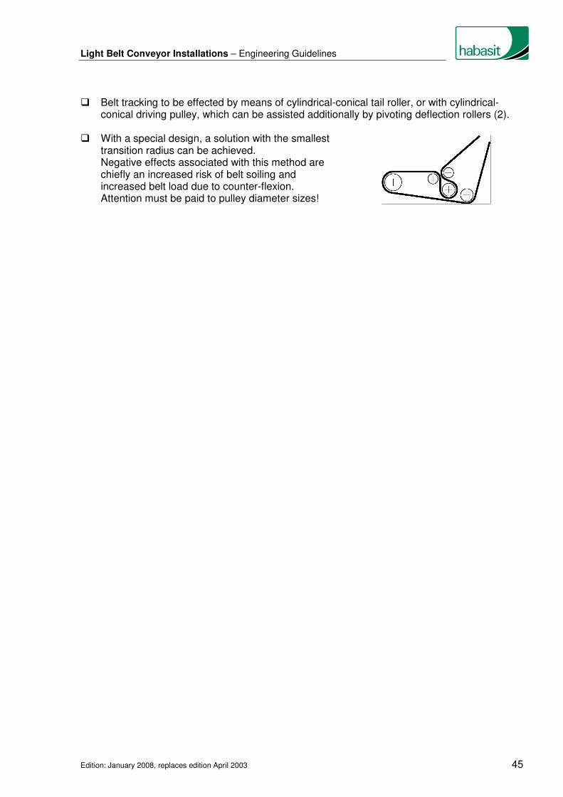
Light Belt Conveyor Installations – Engineering Guidelines
Edition: January 2008, replaces edition April 2003 45
� Belt tracking to be effected by means of cylindrical-conical tail roller, or with cylindrical-conical driving pulley, which can be assisted additionally by pivoting deflection rollers (2).
� With a special design, a solution with the smallest
transition radius can be achieved. Negative effects associated with this method are chiefly an increased risk of belt soiling and increased belt load due to counter-flexion. Attention must be paid to pulley diameter sizes!

Light Belt Conveyor Installations – Engineering Guidelines
Edition: January 2008, replaces edition April 2003 46
22. Knife-edge belt conveyor
With small goods, in particular, the transfer between installations must be as short as possible. To assist in these cases the fitting of knife edges is recommended. A distinction must be made here between fixed knife edges and roller edges. In both cases, light belts with a high degree of longitudinal flexibility and Flexproof joints should be installed, special care being taken that the admissible edge radii requirements are complied with. 22.1 Fixed knife edges
Transfer of goods can take place by means of an edge combined with a roller or by two edges. Frictional heating of the belt and edges occurs at the knife edges. Consideration must be given in these circumstances to the increase of the coefficient of friction that occurs in the joint zone due to this heat. The increased frictional losses result in higher power requirements, which can lead to belt slip at the driving pulley. Merely increasing belt tension will not solve this problem, in fact it makes it worse. Friction and the production of heat at the edges can be minimized by the following measures: � Hard chrome-plated steel edges with a smooth
surface.
� Radius at least 3 mm (0.12 in.), maximum 6 mm (0.24 in.)
� Edge arc of contact to be as small as possible
� Belt tension as low as possible (use driving pulley with friction cover)
� Belt speed as low as possible
� Conveyor belt with sliding, abrasion-resistant running side
� Cooled edges The knife edge has to be rigid and supported where necessary in order to avoid bending. Belt elongation can occur due to edge heating, especially on belts with polyamide traction elements. This elongation is best dealt with by use of a tensioning device that supplies a constant tension (see chapter 6.2). As this ensures an adjustable, constant belt tension under all operating conditions, a reduction of frictional losses and belt wear will be the result.

Light Belt Conveyor Installations – Engineering Guidelines
Edition: January 2008, replaces edition April 2003 47
On shorter installations with one single knife edge the fitting of a cylindrical-conical driving pulley is recommended. Improved belt guidance is achieved with the installation of a snub roller A in tail drive installations and with a pivotable roller B in head drive cases. Belt guidance in conveyors equipped with a knife edge on both the infeed and discharge ends is quite demanding. It is best to minimize the total number of pulleys and rollers in the belt path. For belt-control purposes it is recommended to install roller A (clockwise running direction) or B (anti-clockwise running direction) for pivotable action. For reversing operation pivoted rollers are not suitable for belt guidance, automatic belt controls are therefore frequently fitted (see chapter 16). Traction force is significantly increased as a result of friction against these fixed components. Consequently, increased power consumption and shaft loading must be considered. By minimizing the arc of contact on the nosebars, generation of heat and power requirements can be reduced. 22.2 Rolling edges
The main problem with fixed knife edges are the high frictional losses, but these can be considerably reduced by using rolling edges. The advantages of rolling edges are therefore reduced heat production, lower belt tension and less belt wear. As with all pulleys and rollers, rotating roller edges exert an influence on belt running behavior. It is therefore crucially important that the roller edges are fixed perpendicular to the belt running axis. Where space and installation permit, the roller edge can be slightly crowned to further improve belt tracking. On wide installations, several narrow rollers can be fitted instead of one continuous roller, the advantage here being that the shaft is supported by several bearings thereby reducing shaft deflection.

Light Belt Conveyor Installations – Engineering Guidelines
Edition: January 2008, replaces edition April 2003 48
23. Power turn installations (curved conveyors)
Conveying goods around bends and corners is frequently necessary both for space saving and process control reasons. Curved belt installations are primarily used to change the transportation direction by around 30° to 180°, any angle between these parameters being possible. The spiral curve
conveyor is a special type of curved belt conveyor and is used for coping with height differences in a constricted, or limited space. The chief benefit of curved belt conveyor installations is that the goods conveyed maintain their position in the curve, meaning that these conveying systems are well suited for shingle stream goods, such as newspapers. Their disadvantage is the high cost of belt fabrication and the often complex installations of which they form an important part. Due to the nature of the curved belt, strong transverse forces occur that pull the curved belts inwards towards the center point of the curve. These forces must be absorbed by the installation The best available options for absorbing these transverse forces are detailed below. 23.1 Guidance by pairs of roller
Transverse forces are absorbed by pairs of rollers mounted on the outer belt edge and running on curved rails.
This method demands high precision belt
fabrication with very accurately punched holes along the outer part of the belt.
23.2 Guidance by means of profiles at the belt edge
Guidance here is provided by sewing or welding a profile (plastic bead) to the outer edge of the belt. As the profile runs over angled rollers, the belt is maintained in position.
Extremely accurate positioning of the guide
profile is demanded for this measure to be effective. It is worth mentioning that apart from the high cost of belt fabrication, there are also relatively high energy losses caused by the flexing of the plastic bead through the guide rollers. On the plus side, however, are smooth running and relatively simple belt replacement.
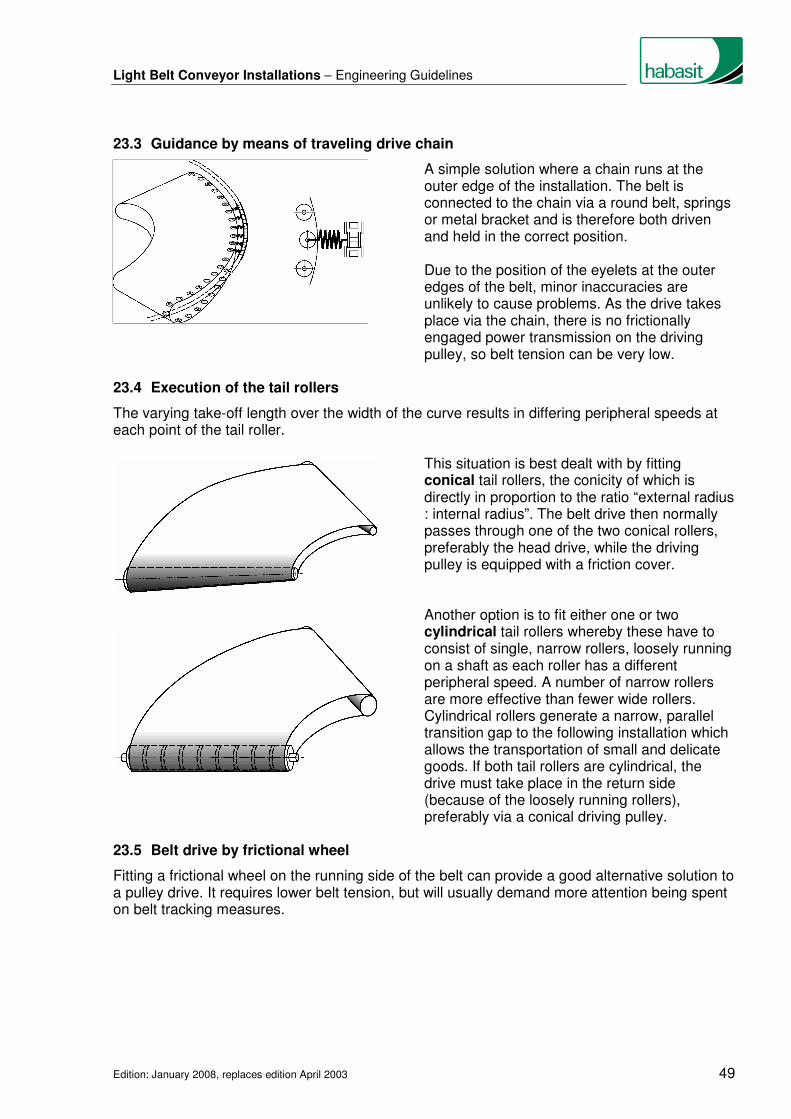
Light Belt Conveyor Installations – Engineering Guidelines
Edition: January 2008, replaces edition April 2003 49
23.3 Guidance by means of traveling drive chain
A simple solution where a chain runs at the outer edge of the installation. The belt is connected to the chain via a round belt, springs or metal bracket and is therefore both driven and held in the correct position.
Due to the position of the eyelets at the outer
edges of the belt, minor inaccuracies are unlikely to cause problems. As the drive takes place via the chain, there is no frictionally engaged power transmission on the driving pulley, so belt tension can be very low.
23.4 Execution of the tail rollers
The varying take-off length over the width of the curve results in differing peripheral speeds at each point of the tail roller. This situation is best dealt with by fitting
conical tail rollers, the conicity of which is directly in proportion to the ratio “external radius : internal radius”. The belt drive then normally passes through one of the two conical rollers, preferably the head drive, while the driving pulley is equipped with a friction cover.
Another option is to fit either one or two
cylindrical tail rollers whereby these have to consist of single, narrow rollers, loosely running on a shaft as each roller has a different peripheral speed. A number of narrow rollers are more effective than fewer wide rollers. Cylindrical rollers generate a narrow, parallel transition gap to the following installation which allows the transportation of small and delicate goods. If both tail rollers are cylindrical, the drive must take place in the return side (because of the loosely running rollers), preferably via a conical driving pulley.
23.5 Belt drive by frictional wheel
Fitting a frictional wheel on the running side of the belt can provide a good alternative solution to a pulley drive. It requires lower belt tension, but will usually demand more attention being spent on belt tracking measures.

Light Belt Conveyor Installations – Engineering Guidelines
Edition: January 2008, replaces edition April 2003 50
23.6 Conveyor belt selection
As a general rule most light conveyor belts are suitable for curved installations. However, it must be remembered that belts on curved installations are subject to bending stresses from all directions. Normal belts, although very flexible longitudinally, tend to be rigid transversely. For this reason, the minimum required pulley diameter dmin (see 7.1), given in the product data
sheets, must be substantially increased for curved belt installations. However, this rule does not apply to special „curved belts“ which have approximately equal elasticity and bending properties both longitudinally and transversely. 23.6 Belt fabrication
Belt fabrication for curved belt conveyors demands great precision during cutting to size and joining. Experience shows that often not the inaccurate fabrication process but inaccurate installation data cause problems. Therefore, exact belt dimensions must always be available. In cases where only the installation data are available, Habasit will be happy to assist in determining the correct belt geometry. In simple terms, a curved belt consists of a number of sections joined to form a cone shaped belt, this construction is then leveled out and tensioned around the tail rollers:

Light Belt Conveyor Installations – Engineering Guidelines
Edition: January 2008, replaces edition April 2003 51
24. 45°/30° belt merges (transfer conveyors)
45°/30° belt merges are core elements in automated material flow systems for infeed and distribution functions. In order to attain closest possible transfer points between belt conveyors and effective belt tracking, the conveyors are designed such that the belts are running over fix nosebars (knife edges) at the angled transfer point *. * Rollers must not be used as they have a negative impact on tracking. Belt tracking measures Generally, tracking of 45°/30° belt merge conveyors is a special challenge. The following measures to enhance belt tracking are empirically based and presented with the understanding that the unique design and operating parameters of individual conveyors present similarly unique challenges in belt tracking.
1 Tracking snub roller (guide roller), arc of contact: min. 30° 2 Additional belt wrap with skewing middle roller 3 Fixed position nosebar � Head drive, usually with snub roller to increase the arc of contact and affect belt tracking without skewing drive pulley.
� Lagging may also be employed to enhance belt traction with reduced tension, and reduce contact pressure of belt with the nosebar in an effort to minimize heat generation. See chapter 28.2 for minimum tension guidelines.
� Both drive and tail pulleys should be crowned with a cylindrical-conical shape.
� Usually cylindrical-conical pulleys alone are not sufficient to track the belt in angular transfer applications. Therefore it is advisable to use snub rollers that may be skewed (guide rollers, see chapter 12) on the approach side of both end rollers.
� Alternatively, on the approach side of the tail roller, an additional belt wrap with a middle roller may be used (2). The middle roller has to made skewable in the Y axis. The deflection rollers must be aligned with the tail roller.

Light Belt Conveyor Installations – Engineering Guidelines
Edition: January 2008, replaces edition April 2003 52
� Sufficient room on conveyor components should be kept available to facilitate lateral belt travel to prevent belt damage when tracking the belt.
� For larger nosebar diameters and/or high belt speeds, tubular steel can effectively serve to minimize heat development in both the belt and related conveyor components;
� Adjustment built in for nosebars should be minimal to reduce the points of adjustment that
can be accessed to influence belt tracking . � Also, please refer to recommendations for nosebar conveyors in chapter 22. Belt selection As the belt traverses the diagonal nosebars it is flexed not only longitudinally, but laterally as well. Therefore, for this type of equipment, specially designed belt types with appropriate lateral flexibility and elastic properties must be used. One should also consider: � The nosebar diameter (and not just end pulleys and snub rollers) when selecting a belt for
use. � Use a belt with low friction on the running side. Tip: Use the online Habasit Belt Selector on www.habasit.com and search for a “Powerturn suitable” belt. For small nosebar radius (≤ 4 mm) select “Nosebar suitable” too. Alternative to curved belt (powerturn) installation Two identical 45° installations can be combined to make a single 90° transfer as an alternative to a curved belt (powerturn) installations (see chapter 23):
� The belt fabrication for 45°/30° merge installations is simpler than for curved belt conveyors, because no circular belt layout is required. It should be noted however, that transferred goods will be rotated and repositioned relative to each other.
� The transfer nosebars should be properly level and aligned to ensure optimal conditions
for stable product transfer.
� Because of the abrupt redirection of product with such a configuration, consideration should be given to belt speed and the use of structural sidewall (that can be adapted to the conveyor framework) to support effective and safe transfer of product at high speed.
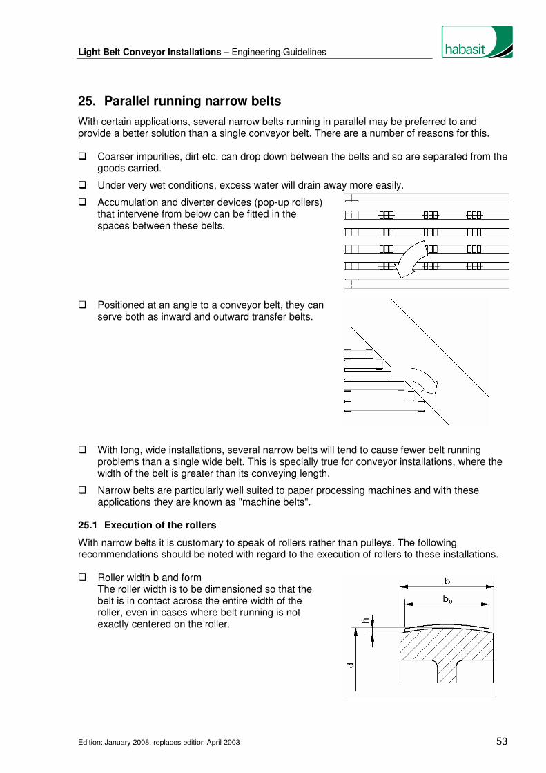
Light Belt Conveyor Installations – Engineering Guidelines
Edition: January 2008, replaces edition April 2003 53
25. Parallel running narrow belts
With certain applications, several narrow belts running in parallel may be preferred to and provide a better solution than a single conveyor belt. There are a number of reasons for this. � Coarser impurities, dirt etc. can drop down between the belts and so are separated from the
goods carried.
� Under very wet conditions, excess water will drain away more easily.
� Accumulation and diverter devices (pop-up rollers) that intervene from below can be fitted in the spaces between these belts.
� Positioned at an angle to a conveyor belt, they can
serve both as inward and outward transfer belts.
� With long, wide installations, several narrow belts will tend to cause fewer belt running
problems than a single wide belt. This is specially true for conveyor installations, where the width of the belt is greater than its conveying length.
� Narrow belts are particularly well suited to paper processing machines and with these applications they are known as "machine belts".
25.1 Execution of the rollers
With narrow belts it is customary to speak of rollers rather than pulleys. The following recommendations should be noted with regard to the execution of rollers to these installations. � Roller width b and form The roller width is to be dimensioned so that the
belt is in contact across the entire width of the roller, even in cases where belt running is not exactly centered on the roller.

Light Belt Conveyor Installations – Engineering Guidelines
Edition: January 2008, replaces edition April 2003 54
Habasit recommendation: b = (1.2 -1.3) bo
bmin = bo + 5 mm (0.2 in.)
Both crowned and uncrowned rollers may be used. The use of crowned rollers can provide
an adequate degree of belt guidance as long as the belt maintains contact with the roller across its total width.
Recommended height of crown h:
Roller diameter d [mm] [in.]
Height of crown h [mm] [in.]
< 40 (1.6)
40 - 112 (1.6 - 4.5)
125 - 140 (5.0 - 5.5)
160 - 180 (6.3 - 7.1)
200 - 224 (8 - 9)
250 - 355 (10 - 14)
0.2 - 0.3 (0.008 - 0.012)
0.3 (0.012)
0.4 (0.016)
0.5 (0.020)
0.6 (0.024)
0.8 (0.030)
Excessive crown height reduces tracking effect. � Running surface
The surface of the roller is to be smooth, max. roughness Ra = 1,6 µm.
Friction can be increased by roughening or knurling the running surface of drive rollers, however this is not to be recommended as it leads to greater belt wear and so shortens belt service life.
� Flanged pulleys Flanged pulleys can only be used where no goods
are being conveyed and generally this means that they are only used on the return side.
The width of the running surface b must be 20% to 30% wider than the belt width bo.
Recommendation for the flange height, hr = 15-30 mm (0.6-1.2 in.)
25.2 Arrangement of the rollers, belt guidance
The positioning and arrangement of the rollers impacts significantly both on belt guidance and belt service life. � Fit at least one crowned roller and several where the conveying belt installation is long
� If rollers are placed in short distance one after another the crowned rollers are to be positioned in such a way that the belt is always flexed in the same direction
� Large arcs of contact will further enhance the tracking effect of crowned rollers
� All rollers must be positioned exactly at right-angles to the direction in which the belt is running; this applies particularly in the case of cylindrical rollers

Light Belt Conveyor Installations – Engineering Guidelines
Edition: January 2008, replaces edition April 2003 55
� The slanting or angling of rollers to correct belt running problems is not to be recommended and must be avoided completely with reversing operations
� The use of cylindrical continuous shafts instead of rollers can only be effective where there are sufficient numbers of crowned rollers to ensure correct belt guidance. Where this is not the case the shaft itself must be fitted with the appropriate crowns.
25.3 Belt drive and take-up
Parallel running belts can be driven both by individual drive rollers or by means of a continuous shaft. In all cases belts must be individually tensioned. The fitting of adjustable rollers, spring- or weight-loaded tensioning devices is one way of achieving this result while the use of elastic belts (e.g. elastic Hamid machine tapes) or Polycord round belts negates the need to use any tensioning device.
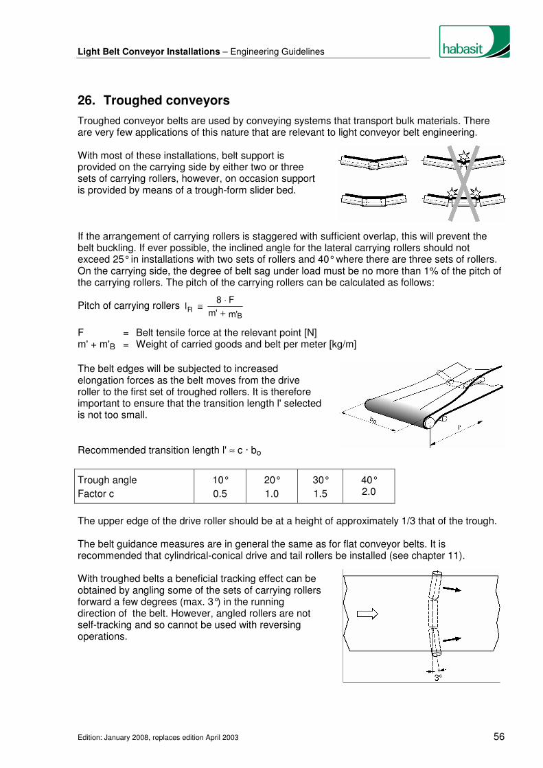
Light Belt Conveyor Installations – Engineering Guidelines
Edition: January 2008, replaces edition April 2003 56
26. Troughed conveyors
Troughed conveyor belts are used by conveying systems that transport bulk materials. There are very few applications of this nature that are relevant to light conveyor belt engineering. With most of these installations, belt support is provided on the carrying side by either two or three sets of carrying rollers, however, on occasion support is provided by means of a trough-form slider bed. If the arrangement of carrying rollers is staggered with sufficient overlap, this will prevent the belt buckling. If ever possible, the inclined angle for the lateral carrying rollers should not exceed 25° in installations with two sets of rollers and 40° where there are three sets of rollers. On the carrying side, the degree of belt sag under load must be no more than 1% of the pitch of the carrying rollers. The pitch of the carrying rollers can be calculated as follows:
Pitch of carrying rollers 'm'm
F8l
BR +
⋅≅
F = Belt tensile force at the relevant point [N] m' + m'B = Weight of carried goods and belt per meter [kg/m]
The belt edges will be subjected to increased elongation forces as the belt moves from the drive roller to the first set of troughed rollers. It is therefore important to ensure that the transition length l' selected is not too small.
Recommended transition length l' ≈ c · bo
Trough angle
Factor c
10°
0.5
20°
1.0
30°
1.5
40° 2.0
The upper edge of the drive roller should be at a height of approximately 1/3 that of the trough. The belt guidance measures are in general the same as for flat conveyor belts. It is recommended that cylindrical-conical drive and tail rollers be installed (see chapter 11). With troughed belts a beneficial tracking effect can be obtained by angling some of the sets of carrying rollers forward a few degrees (max. 3°) in the running direction of the belt. However, angled rollers are not self-tracking and so cannot be used with reversing operations.

Light Belt Conveyor Installations – Engineering Guidelines
Edition: January 2008, replaces edition April 2003 57
In installations with two sets of carrying rollers care must be taken that the conveyor belt makes contact across at least half the roller’s width while in a tensioned but unloaded state. With systems with three sets of carrying rollers the belt should always be completely in contact with the center roller while in a tensioned but unloaded state.
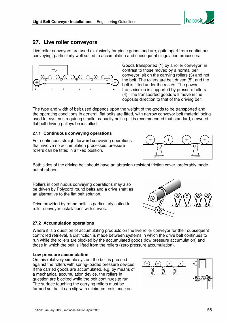
Light Belt Conveyor Installations – Engineering Guidelines
Edition: January 2008, replaces edition April 2003 58
27. Live roller conveyors
Live roller conveyors are used exclusively for piece goods and are, quite apart from continuous conveying, particularly well suited to accumulation and subsequent singulation processes. Goods transported (1) by a roller conveyor, in
contrast to those moved by a normal belt conveyor, sit on the carrying rollers (3) and not the belt. The rollers are belt driven (5), and the belt is fitted under the rollers. The power transmission is supported by pressure rollers (4). The transported goods will move in the opposite direction to that of the driving belt.
The type and width of belt used depends upon the weight of the goods to be transported and the operating conditions.In general, flat belts are fitted, with narrow conveyor belt material being used for systems requiring smaller capacity belting. It is recommended that standard, crowned flat belt driving pulleys be installed. 27.1 Continuous conveying operations
For continuous straight forward conveying operations that involve no accumulation processes, pressure rollers can be fitted in a fixed position. Both sides of the driving belt should have an abrasion-resistant friction cover, preferably made out of rubber. Rollers in continuous conveying operations may also be driven by Polycord round belts and a drive shaft as an alternative to the flat belt solution. Drive provided by round belts is particularly suited to roller conveyor installations with curves. 27.2 Accumulation operations
Where it is a question of accumulating products on the live roller conveyor for their subsequent controlled retrieval, a distinction is made between systems in which the drive belt continues to run while the rollers are blocked by the accumulated goods (low pressure accumulation) and those in which the belt is lifted from the rollers (zero pressure accumulation). Low pressure accumulation On this relatively simple system the belt is pressed against the rollers with spring-loaded pressure devices. If the carried goods are accumulated, e.g. by means of a mechanical accumulation device, the rollers in question are blocked while the belt continues to run. The surface touching the carrying rollers must be formed so that it can slip with minimum resistance on

Light Belt Conveyor Installations – Engineering Guidelines
Edition: January 2008, replaces edition April 2003 59
the blocked rollers, but at the same time continue to drive the other carrying rollers reliably. On the driving pulley surface, the belt must have a high coefficient of friction (preferably rubber).
Zero pressure accumulation On this more costly system, the pressure rollers are moved away from the carrying rollers during the accumulation process. The goods being carried will therefore stop moving once the rollers are disconnected from the drive. However, if they are to be conveyed further the pressure rollers are simply returned to their operational position so pressing the drive belt back on to the rollers. In this fashion different sections of the roller conveyor can be disconnected and reconnected to the drive completely independently of each other. The pressure roller lifting device itself can be mechanically, pneumatically or electromechanically operated, while the control sensors are mechanical, electrical, pneumatic or optical.
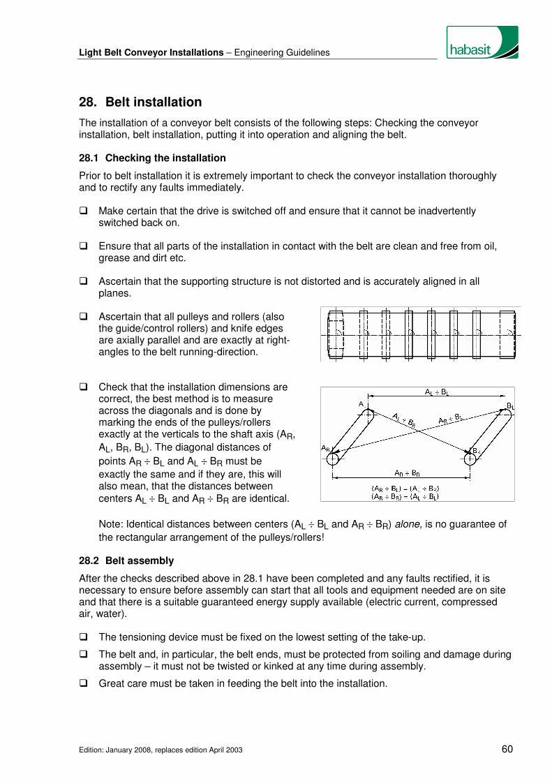
Light Belt Conveyor Installations – Engineering Guidelines
Edition: January 2008, replaces edition April 2003 60
28. Belt installation
The installation of a conveyor belt consists of the following steps: Checking the conveyor installation, belt installation, putting it into operation and aligning the belt. 28.1 Checking the installation
Prior to belt installation it is extremely important to check the conveyor installation thoroughly and to rectify any faults immediately. � Make certain that the drive is switched off and ensure that it cannot be inadvertently
switched back on. � Ensure that all parts of the installation in contact with the belt are clean and free from oil,
grease and dirt etc. � Ascertain that the supporting structure is not distorted and is accurately aligned in all
planes. � Ascertain that all pulleys and rollers (also
the guide/control rollers) and knife edges are axially parallel and are exactly at right-angles to the belt running-direction.
� Check that the installation dimensions are
correct, the best method is to measure across the diagonals and is done by marking the ends of the pulleys/rollers exactly at the verticals to the shaft axis (AR,
AL, BR, BL). The diagonal distances of
points AR ÷ BL and AL ÷ BR must be
exactly the same and if they are, this will also mean, that the distances between
centers AL ÷ BL and AR ÷ BR are identical.
Note: Identical distances between centers (AL ÷ BL and AR ÷ BR) alone, is no guarantee of
the rectangular arrangement of the pulleys/rollers! 28.2 Belt assembly
After the checks described above in 28.1 have been completed and any faults rectified, it is necessary to ensure before assembly can start that all tools and equipment needed are on site and that there is a suitable guaranteed energy supply available (electric current, compressed air, water). � The tensioning device must be fixed on the lowest setting of the take-up.
� The belt and, in particular, the belt ends, must be protected from soiling and damage during assembly – it must not be twisted or kinked at any time during assembly.
� Great care must be taken in feeding the belt into the installation.

Light Belt Conveyor Installations – Engineering Guidelines
Edition: January 2008, replaces edition April 2003 61
� In the case of skived, glued joints, care needs to be taken to ensure that goods will not damage or tear the joint. This is particularly important when accumulation take place.
� If the belt is to be joined on the installation, the joining instructions must be carefully
followed.
� When tensioning the belt, ensure that the tension roller is adjusted exactly parallel to the belt running-direction and that it remains so after tensioning has been completed.
� Although in practice conveyor belts are usually tensioned by feel, it is important to make sure that the driving pulley can drive the belt without slipping even under maximum load.
� The minimum and maximum admissible initial tension εo will vary according to the material
used for the traction element.
Traction element material Min. initial tension εomin Max. initial tension εomax
Polyester fabric
Polyamide fabric
Aramid fabric
0.3%
0.5%
0.2%
around 1%
around 3%
around 0.3%
Where the correct initial tension εo is known, i.e. by calculation, it is this figure that should
be used. � Initial tension is checked by making two reference marks on the untensioned belt at a
certain distance apart x (x = 100 %). The marks should ideally be at both edges of the belt, but not where it is joined.
The belt is then tensioned until the measuring marks have reached the required elongation
(x + εo).
Example: Required initial tension εo = 0.5%,
Distance between marks before tensioning x = 1000 mm (39.37 in.)
Distance between marks after tensioning x + εo = 1000 mm + 5 mm = 1005 mm
(39.37 in. + 0.2 in. = 39.57 in.)
� Once the belt has completed at least one circuit of the installation, the distance (x + εo) is to
be measured again and then corrected where necessary.

Light Belt Conveyor Installations – Engineering Guidelines
Edition: January 2008, replaces edition April 2003 62
28.3 Belt alignment
For the belt to run fault free it is essential that the conveying installation itself is accurately aligned and that the belt is fitted correctly and by properly trained personnel. � At first run the conveyor belt only slowly or with frequent stops and starts so that any run-off
tendency can be detected quickly and rectified before any damage occurs.
� Carry out all belt adjustments in small steps, working on only one roller or pulley at a time. If too many pulleys or rollers are adjusted at the same time, the operating characteristics of the system will become unstable and will vary with different operating conditions.
� After each adjustment allow a few belt circuits to take place before making any further corrections to the belt.
� Make the first corrections at points where damage to the belt is most likely.
� Bear in mind that each adjustment made can result in further adjustments being necessary elsewhere on the installation.
� Where a guide/control roller (see chapter 12) is installed on the running-on side (with head drive) or in front of the driving pulley (with tail drive), the belt must first of all be aligned with this.
� Cylindrical pulleys and rollers which are not at right angles to the belt running-direction are not self-tracking and so, with changes in run-off tendency, will need to be reset. This is not practical and so the position of these pulleys and rollers should not be altered with reversing operations.
� In the case of belts with guiding profiles (see chapter 15), the belt is to be aligned under no-load conditions so that the profile can run in the grooves without running against the sides.
Light Belt Conveyor Installations – Engineering Guidelines
Edition: January 2008, replaces edition April 2003 63
29. Maintenance and cleaning
29.1 Maintenance
Apart from cleaning, conveyor belts made from synthetic materials require no maintenance. A periodic check of the belt tension is recommended, however, particularly where operating conditions are harsh (e.g. frequent starts under full load, significant temperature fluctuations, etc.). It is important that all parts of the installation that come into contact with the belt are kept as clean as possible. Oil, grease, moisture, rust, dirt, traces of conveyed products etc. on pulleys, rollers, slider bed and other parts of the installation in contact with the belt may cause operational and belt performance problems and will certainly shorten belt service life. 29.2 Cleaning
The importance of belt cleanliness with regard to drive, proper tracking response and belt life cannot be over emphasized. Dirt on the conveying side of the belt may also lead to process breakdowns. Obviously hygiene is of particular significance in the food sector where a number of special cleaning measures must be implemented. Listed below a few general points on the cleaning of synthetic conveyor belts: � Cleaning should, wherever and whenever possible, be carried out when the installation is at
rest (safety aspect)
� In the case of light dirt deposits (dust etc.), clean with a soft cloth; dry or moistened with cold or warm water
� Oily, greasy soiling can be removed with hot water and a general, nonabrasive household detergent (low foaming types can aid the rinsing process)
� Spot cleaning can be performed via a damp rag application of a suitable solvent (see table)
� Heavy soiling can be removed by scrubbing with hot soapy water or washing with a mild solvent (see table)
� The following table shows the relative suitability of common detergents and solvents for cleaning of synthetic conveyor belts:

Light Belt Conveyor Installations – Engineering Guidelines
Edition: January 2008, replaces edition April 2003 64
Habasit Category of resistance
1 2 3 4 5 6 7 8 9 10
Material cover (conveying side)
PA NBR PUR
Hamid
PVC* EPDM NBR PUR
SI
TPU PUR+TPU NBR+TPU
SI+TPU
PVC** PTFE TPO Habilene
Material traction layer (fabric)
PA PA AR
Hamid CEL
PET PET PET Glas
PET AR BW
PET AR PET PET
Neutral 1)
☺ ☺ ☺ ☺ ☺ ☺ ☺ ☺ ☺ ☺
Cleaning Alkaline 2)
☺ ☺ ☺ t ☺ t ☺ ☺ ☺ ☺
agent Acid 3)
� � ☺ ☺ ☺ ☺ ☺ ☺ ☺ ☺
Chloric 4)
t t t t t t t ☺ ☺ ☺
Alcohols 5)
☺ ☺ t ☺ ☺ t ☺ ☺ ☺ ☺
AR PA PET
PVC*
PVC**
PUR TPU TPO PTFE NBR EPDM SI CEL BW
List of materials Aramide Polyamide Polyester
Polyvinylchloride (Monomer softener)
Polyvinylchloride (Polymer softener) Polyurethane cross-linked Polyurethane thermoplastic Polyolefin thermoplastic Polytetrafluorethylene (Teflon) Acrylonitrile-butadiene rubber Ethylene propylene terpolymer rubber Silicone Cellulose Cotton
☺
t �
1) 2) 3) 4) 5)
Explanation of characters Resistant at standard atmosphere (23°C, 50% rel. humidity of air) Contingently resistant Depending on concentration, duration of impact, thermic and mechanical strain, discoloration, sweling, embrittlement or abrasion are possible Not resistant also at low concentration Examples of cleaning agents Water Soap water, soda, ammonia solution Acetics,citric acid Javel water (sodium hypochloride solution <1%) Ethanol, methanol, methylated spirit
� Unsuitable solvents are: - Aromatic compounds (benzene, toluene, xylene) - Chlorinated hydrocarbons (trichloroethylene, tetrachlorethylene, tetrachlorohydrogen)
- Ketones (acetone, methylethyl ketone)
� When working with flammable and/or noxious chemicals, it is vital for you to observe all applicable safety precautions (refer to the corresponding safety data sheets for the chemicals to be employed).
� Please consult our list "Chemical resistance" for suitability prior to using chemical substances for cleaning our belts.
� When cleaning with hot water or steam, take care not to exceed the maximum permitted temperature for the belt. Caution: Inappropriate cleaning with high-pressure cleaning apparatus may damage the belt.
� The belt should be dried after being cleaned with water.

Light Belt Conveyor Installations – Engineering Guidelines
Edition: January 2008, replaces edition April 2003 65
� Do not immerse belts in water or other fluids for long periods. This can result in irreversible dimensional changes (shrinkage), camber, color changes, degradation of the materials, layer separation or premature splice failure etc.
� Where brushes are used for cleaning, use only those with soft bristles.
� Special and statutory requirements apply for the cleaning and disinfecting of conveyor belts in the food industry. These regulations must be complied with.
� For further information, please contact your Habasit specialist.

Light Belt Conveyor Installations – Engineering Guidelines
Edition: January 2008, replaces edition April 2003 66
30. Storage
Unfavorable storage conditions or improper handling result in changes in the physical characteristics of most plastic products. Such changes can, among other things, shorten the service life of the product.
30.1 Storage conditions
The belts should be protected against damage, contamination, moisture, extreme temperatures and UV light, ideally they should be stored in a dark room or in opaque plastic wrap which will also protect the belt against dust and other contaminants. Products containing polyamide should always be wrapped airtight , to avoid undesirable absorbtion of humidity or drying out. Habasit belts should preferably be stored in their original packaging. 30.2 Storage
Rolls of narrow belts can be stored horizontally on boards or pallets. Several rolls of such products can be stacked as long as the resulting weight does not crush or deform the belts. Joined belts should be rolled on a hard tube (no smaller than the recommended minimum pulley diameter for the belt) as this will prevent them from crimping. Heavy rolls should preferably be stored stored suspended with the aid of a steel bar or laying on a thick, soft rubber foam bedding.
30.3 Handling of heavy rolls
To lift a large roll of belts, insert a steel bar through the hole at the core of the roll and attach it to a hoist with two rope slings or chains attached to a crossbeam. To prevent damage to the belt edges by the ropes or chains, the crossbeam must be longer than the width of the roll. Belt rolls can also be transported using forklift trucks. Take care that the outer belt layers are not damaged by the fork edges.

Light Belt Conveyor Installations – Engineering Guidelines
Edition: January 2008, replaces edition April 2003 67
Index
Accumulation ....................................................................................................................... 39
Accumulation (live roller conveyors)..................................................................................... 56
Additional belt wrap ............................................................................................................. 35
Automatic belt control .......................................................................................................... 34 Belt alignment...................................................................................................................... 60
Belt assembly ...................................................................................................................... 58
Belt cleaning systems .......................................................................................................... 41
Belt conveyor components..................................................................................................... 6
Belt installation..................................................................................................................... 58
Belt scanning combined with pivotable carrying roller .......................................................... 36
Belt support by slider bed ...................................................................................................... 9
Belt support by carrying rollers............................................................................................. 10
Belt support on the return side ............................................................................................. 10
Belt tracking in general ........................................................................................................ 25
Belt tracking, further measures ............................................................................................ 35 Carrying rollers with adhesive covers................................................................................... 35
Center drive ......................................................................................................................... 12
Checking the installation (before belt installation) ................................................................ 58
Cleaning .............................................................................................................................. 61
Constant-force tensioning device......................................................................................... 14
Continuous conveying operations (live roller conveyors)...................................................... 56
Control rollers ...................................................................................................................... 29
Corner belt installations ....................................................................................................... 50
Crowned pulley .................................................................................................................... 28
Cylindrical-conical pulley...................................................................................................... 27 Deflection roller.................................................................................................................... 23
Diverting of conveyed goods................................................................................................ 39
Drive .................................................................................................................................... 11
Driving pulley ....................................................................................................................... 20 Feeding of goods ................................................................................................................. 39
Fixed tensioning device ....................................................................................................... 14
Fixing of pulleys and rollers.................................................................................................... 8

Light Belt Conveyor Installations – Engineering Guidelines
Edition: January 2008, replaces edition April 2003 68
Guide rollers ........................................................................................................................ 29
Guiding of short, wide belts.................................................................................................. 37
Guiding profiles.................................................................................................................... 32 Handling .............................................................................................................................. 64
Head drive ........................................................................................................................... 11 Inclined rollers on the return side ......................................................................................... 31 Knife edges, fixed ................................................................................................................ 45 Lateral guide rollers ............................................................................................................. 36
Live roller conveyors ............................................................................................................ 56 Maintenance ........................................................................................................................ 61
Minimum pulley diameter ..................................................................................................... 16 Parallel running narrow belts................................................................................................ 51
Pivotable carrying rollers...................................................................................................... 30
Pivoted rollers on the carrying side ...................................................................................... 36
Power transmission (frictional engaged drive)...................................................................... 11
Power turn installations (curved conveyors)......................................................................... 47
Pulley and roller fixing............................................................................................................ 8
Pulley diameter .................................................................................................................... 16
Pulley width ......................................................................................................................... 19
Pulleys with an adjustable aligning profile ............................................................................ 35 Rollers with spiral-shaped grooves ...................................................................................... 35
Rolling edges....................................................................................................................... 46 Slider bed .............................................................................................................................. 9
Smallest diameter of drive pulleys........................................................................................ 20
Smallest pulley diameter with respect to deflection .............................................................. 16
Snub roller ........................................................................................................................... 23
Steep angle conveyor installation ........................................................................................ 42
Storage................................................................................................................................ 64
Supporting structure .............................................................................................................. 8
System parts, figure............................................................................................................... 6 Tail drive .............................................................................................................................. 12
Tail roller.............................................................................................................................. 23

Light Belt Conveyor Installations – Engineering Guidelines
Edition: January 2008, replaces edition April 2003 69
Tandem drive....................................................................................................................... 12
Tension roller ....................................................................................................................... 24
Tensioning device................................................................................................................ 14
Troughed conveyors ............................................................................................................ 54 Variations on standard systems ............................................................................................. 6
V-shaped grooves in the slider bed...................................................................................... 36 Z-conveyor installations ....................................................................................................... 43


![1 SERIES Belt Conveyor System B090 - Bett Sistemi Srl€¦ · CONVEYOR BELT DEVELOPMENT CALCULATION FORMULA Conveyor belt length = 300 + {[(L-94)-(2• Conveyor belt thick. )]•2}](https://img.pdfslide.us/doc/110x75/5ad3c4047f8b9a48398b7ae4/1-series-belt-conveyor-system-b090-bett-sistemi-conveyor-belt-development-calculation.jpg)