Embed Size (px)
Citation preview
NOTE: This unit may not be factory set at FP# 1.
140714M53
To +VDC (fuse @ 2A)..............RED
To Chassis Ground.............BLACK
For Synchronization.........YELLOW Connect YELLOW wires of all heads together for synchronization (All heads must be set at the same pattern)
For Simultaneous or Alternating Flash: 1. Apply +VDC to RED and YELLOW wires simulta- neously to enter Grouping mode; lighthead will display short (single or double) flashes: .Single flash = Group1 .Double flash = Group2 2. Remove YELLOW wire from +VDC and momentarily apply to +VDC to change Groups: .Heads in the same Group flash together. .Group1 Heads alternate with Group2 Heads. 3. Disconnect power to save and exit Grouping mode.
For Flash Patterns:Momentarily apply +VDC to YELLOW wire:.once for next pattern .quickly three times for FP#1
Light Assembly Installation
NOTE: Lighthead mounting location may vary dependingon the design of the vehicle light assembly.
1 Random2 Steady3 Single 4 Mega5 Double6 Triple
7 Quad8 Quint9 Ultra10 Single-Quad11 Single H/L12
Flash PatternsFP#
Single-Triple-Quint
WARNING: DO NOT cover heat sink with silicone. It may cause damage to the product and void warranty.
1. Remove the Corner/Head/Tail light from vehicle. 2. Select location to mount lighthead. 3. Drill 1 inch diameter hole to the light assembly. 4. Insert lighthead into hole and secure with supplied screws.5. Apply silicone (user-supplied) for better seal.
OPERATIONS
Foam
Mountingscrew holes
1 inch dia. hole
Sheet metal screw
Gasket
VEHICLELIGHT
ASSEMBLY
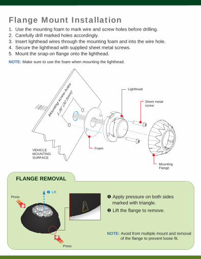
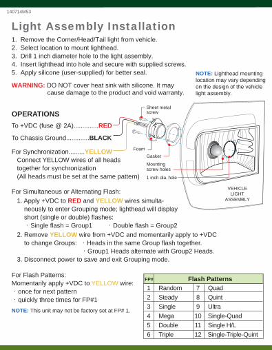
NOTE: Avoid from multiple mount and removal of the flange to prevent loose fit.
Flange Mount Installation
NOTE: Make sure to use the foam when mounting the lighthead.
1. Use the mounting foam to mark wire and screw holes before drilling. 2. Carefully drill marked holes accordingly. 3. Insert lighthead wires through the mounting foam and into the wire hole.4. Secure the lighthead with supplied sheet metal screws.5. Mount the snap-on flange onto the lighthead.
FLANGE REMOVAL
Press
Press
Lift
Apply pressure on both sides marked with triangle. Lift the flange to remove.
Mou
nting
screw ho
les
VEHICLEMOUNTINGSURFACE
1.28
” (32
.5mm)
Foam
MountingFlange
Lighthead
Sheet metalscrew